EP4226116B1 - Airgap measurement in a generator of a wind turbine - Google Patents
Airgap measurement in a generator of a wind turbine Download PDFInfo
- Publication number
- EP4226116B1 EP4226116B1 EP21823838.4A EP21823838A EP4226116B1 EP 4226116 B1 EP4226116 B1 EP 4226116B1 EP 21823838 A EP21823838 A EP 21823838A EP 4226116 B1 EP4226116 B1 EP 4226116B1
- Authority
- EP
- European Patent Office
- Prior art keywords
- rotor
- stator
- distance measuring
- air gap
- sensors
- Prior art date
- Legal status (The legal status is an assumption and is not a legal conclusion. Google has not performed a legal analysis and makes no representation as to the accuracy of the status listed.)
- Active
Links
Images




Classifications
-
- G—PHYSICS
- G01—MEASURING; TESTING
- G01B—MEASURING LENGTH, THICKNESS OR SIMILAR LINEAR DIMENSIONS; MEASURING ANGLES; MEASURING AREAS; MEASURING IRREGULARITIES OF SURFACES OR CONTOURS
- G01B7/00—Measuring arrangements characterised by the use of electric or magnetic techniques
- G01B7/14—Measuring arrangements characterised by the use of electric or magnetic techniques for measuring distance or clearance between spaced objects or spaced apertures
-
- F—MECHANICAL ENGINEERING; LIGHTING; HEATING; WEAPONS; BLASTING
- F03—MACHINES OR ENGINES FOR LIQUIDS; WIND, SPRING, OR WEIGHT MOTORS; PRODUCING MECHANICAL POWER OR A REACTIVE PROPULSIVE THRUST, NOT OTHERWISE PROVIDED FOR
- F03D—WIND MOTORS
- F03D17/00—Monitoring or testing of wind motors, e.g. diagnostics
- F03D17/027—Monitoring or testing of wind motors, e.g. diagnostics characterised by the component being monitored or tested
- F03D17/036—Generators
-
- G—PHYSICS
- G01—MEASURING; TESTING
- G01D—MEASURING NOT SPECIALLY ADAPTED FOR A SPECIFIC VARIABLE; ARRANGEMENTS FOR MEASURING TWO OR MORE VARIABLES NOT COVERED IN A SINGLE OTHER SUBCLASS; TARIFF METERING APPARATUS; MEASURING OR TESTING NOT OTHERWISE PROVIDED FOR
- G01D11/00—Component parts of measuring arrangements not specially adapted for a specific variable
- G01D11/30—Supports specially adapted for an instrument; Supports specially adapted for a set of instruments
-
- F—MECHANICAL ENGINEERING; LIGHTING; HEATING; WEAPONS; BLASTING
- F05—INDEXING SCHEMES RELATING TO ENGINES OR PUMPS IN VARIOUS SUBCLASSES OF CLASSES F01-F04
- F05B—INDEXING SCHEME RELATING TO WIND, SPRING, WEIGHT, INERTIA OR LIKE MOTORS, TO MACHINES OR ENGINES FOR LIQUIDS COVERED BY SUBCLASSES F03B, F03D AND F03G
- F05B2260/00—Function
- F05B2260/83—Testing, e.g. methods, components or tools therefor
-
- Y—GENERAL TAGGING OF NEW TECHNOLOGICAL DEVELOPMENTS; GENERAL TAGGING OF CROSS-SECTIONAL TECHNOLOGIES SPANNING OVER SEVERAL SECTIONS OF THE IPC; TECHNICAL SUBJECTS COVERED BY FORMER USPC CROSS-REFERENCE ART COLLECTIONS [XRACs] AND DIGESTS
- Y02—TECHNOLOGIES OR APPLICATIONS FOR MITIGATION OR ADAPTATION AGAINST CLIMATE CHANGE
- Y02E—REDUCTION OF GREENHOUSE GAS [GHG] EMISSIONS, RELATED TO ENERGY GENERATION, TRANSMISSION OR DISTRIBUTION
- Y02E10/00—Energy generation through renewable energy sources
- Y02E10/70—Wind energy
- Y02E10/72—Wind turbines with rotation axis in wind direction
Definitions
- the invention relates to a method and a device for measuring the airgap between the stator and the rotor of an electric generator. Particularly, but not exclusively, can be applied to an electric generator for a wind turbine.
- the airgap which is formed between the stator and a rotor in a wind turbine electric generator is an important design feature that contributes to determines the overall efficiency of the wind turbine.
- the airgap During the assembly process of the electric generator, it is known to measure the airgap after the pairing between stator and rotor.
- the airgap has normally a thickness in the range of some millimetres and is therefore not well accessible. Nevertheless, the production must record the values as part of the quality check. Furthermore, the airgap measurement is possibly provided to the customer as a critical quality reference in the future.
- This measurement may be performed manually by technicians, who have to crawl into the inside of the stator and use calliper gauges that are applied through radial airducts in the stator segments to measure the airgap. Multiple measurements are performed along the circumference of the generator. This procedure implies a plurality of inconveniences, for example:
- the document DE102016122862 A1 discloses a method for performing a plurality of measurements in the air gap between a stator and a rotor of a generator for a wind turbine according to the state of the art.
- One aspect of the invention relates to a method for performing a plurality of measurements in the air gap between a stator and a rotor of a generator for a wind turbine, the rotor being rotatable with respect to the stator about a rotational axis, the method including the steps of:
- said one or more parameter(s) associated with the air gap may be any of:
- the nominal airgap may be reduced in turbine generations due to higher confidence of the airgap, due to the above-described measurement procedure.
- the production can fulfill quality assurance step faster, with higher data accuracy in less manual work (faster process). It also supports to understand assembly factors better how they impact the airgap and thus optimize the assembly to achieve an optimal airgap.
- said steps of mounting rotating and measuring are first performed with the plurality of distance measuring sensors mounted on one of the stator and rotor and then said steps of mounting rotating and measuring are again performed with the plurality of distance measuring sensors (110) mounted on the other of rotor and stator.
- a first plurality of distance measuring sensors are mounted on a first surface of the stator and a second plurality of distance measuring sensors are mounted on a second surface of the rotor, said first and second surfaces facing the air gap.
- At least a portion of plurality of distance measuring sensors are fixed to a longitudinal support, said longitudinal support being fixed on a surface of the stator and/or the rotor, said surface facing the air gap, during said step of mounting.
- Another aspect of the invention relates to a measurement device for performing a plurality of measurements in the air gap between a stator and a rotor of a generator for a wind turbine, the measurement device including:
- the longitudinal support may be in form of a stick along which the plurality of sensors is attached.
- the sensors may be regularly distributed along the length of the longitudinal support.
- the longitudinal support may be oriented during the measurement operations along the rotational axis of the electric generator or inclined with respect thereto of an inclination angle comprised between 0 and 10 degree. Such inclination angle may depend on the geometric constraints of the stator and/or rotor.
- the longitudinal support with the plurality of sensors may be fixed during the measurement operations to a surface of the stator or to a surface of the rotor, such surfaces of the stator and the rotor facing the airgap.
- the longitudinal support with the plurality of sensors may be fixed during the measurement operations to an external surface of the stator or to an internal surface of the rotor.
- the longitudinal support with the plurality of sensors may be fixed during the measurement operations to an external surface of the rotor or to an internal surface of the stator.
- the longitudinal support with the plurality of sensors may be fixed to one or more magnets facing the airgap.
- the measurement device may include two longitudinal supports to be respectively fixed during the measurement operations to a surface of the stator and to a surface of the rotor, such surfaces of the stator and the rotor facing the airgap.
- the longitudinal support with the plurality of sensors may be fixed at positions, which are radially distanced from the airgap.
- the plurality of distance measuring sensors are capacitive sensors.
- the sensors may be capacitive film sensors or capacitive flat sensors.
- the sensors may be capacitive tactile sensor or eddy current sensors.
- the longitudinal support is fixed to the stator or the rotor by means of at least one thread or similar thin material.
- Each thread may grasp the longitudinal support and extend through a respective air duct of the stator, the thread being tightened in such a way that the longitudinal support is pushed against the external side of the stator.
- Such embodiments permit a strong fixation of the longitudinal support onto the stator surface.
- the fixing procedure is characterized by easy handability with tightening, removability without destroying materials and reusability.
- the longitudinal support is fixed to the stator or the rotor by applying un under-pressure between the longitudinal support and a surface of the stator or the rotor facing the air gap, the under-pressure pushing the longitudinal support towards the surface of the stator or the rotor facing the air gap.
- the longitudinal support may comprise a channel having an opening to be attached to a surface of the rotor facing the air gap, the measurement device comprising an under-pressure generator to be connected to the channel for evacuating air is activated, air can be evacuated from the opening.
- Fixing by applying under-pressure allows secure and strong fixation of the longitudinal support onto a rotor surface, e.g. a magnet surface. Removability without destroying materials and reusability can be achieved.
- a thin design is possible for adapting to the tight space conditions in the airgap.
- FIG. 1 shows a wind turbine 1 according to the invention.
- the wind turbine 1 comprises a tower 2, which is mounted on a non-depicted foundation.
- a nacelle 3 is arranged on top of the tower 2.
- the wind turbine 1 further comprises at least a wind rotor 5 having a hub and at least one blade 4 (in the embodiment of Figure 1 , the wind rotor comprises three blades 4, of which only two blades 4 are visible).
- the wind rotor 5 is rotatable around a rotational longitudinal axis Y.
- the blades 4 extend substantially radially with respect to the longitudinal rotational axis Y.
- the terms axial, radial and circumferential in the following are made with reference to the longitudinal rotational axis Y.
- the wind turbine 1 comprises at least one electric generator 11, including a stator 20 and a rotor 30.
- the rotor 30 is rotatable with respect to the stator 20 about the longitudinal rotational axis Y.
- the wind rotor 5 is coupled with the rotor 30, in order to rotate about the rotational longitudinal axis Y.
- the electric generator 11 comprise an airgap 15 radially interposed between the stator 20 and the rotor 30, the airgap 15 extending circumferentially about the rotational axis Y.
- the rotor 30 is radially external to the stator 20. According to other embodiments (not show), the rotor may be radially internal to the stator.
- FIG. 2 shows an exploded view of the electrical generator 11 with the rotor 30 and the stator 20.
- the stator 20 comprises a cylindrical inner core to which six segments 45 are attached. Each segment 45 has a circumferential angular extension of 60°. According to other embodiments of the present invention, the stator 20 comprises a plurality of segments having a number of segments different from six. According to another possible embodiment of the present invention, the stator 20 is not segmented, i.e. the stator includes one single segment covering the entire angular extension of 360°.
- the rotor 30 has a conventional structure with a plurality of circumferentially distributed rotor permanent magnets 31. The magnets 31 are distributed on an inner side of the rotor 30 according to axial columns. Each column of magnets comprises a plurality of magnets 31 (two magnets 31 in the embodiment of figure 2 ) aligned along the rotational axis Y.
- a method 100 for performing a plurality of measurements in the air gap 15 includes the following steps:
- Such parameter(s) associated with the air gap 15 may be one or more of:
- Figure 3 shows a first embodiment of a block diagram of a method 100.
- the method 100 comprises mounting a plurality of distance measuring sensors 210 on a surface of the stator 20 facing the air gap 15 ( figure 5 and 6 ).
- the sensors 210 may be attached to an external surface of a stator segment 45.
- the plurality of distance measuring sensors 110 may be alternatively mounted on a surface of the rotor 30 facing the air gap 15.
- the sensors 210 are fixed to the stator 20 or rotor 30 in such a way that each distance measuring sensor 210 is distanced from the other distance measuring sensors 210 along the rotational axis Y.
- the method 100 comprises rotating the rotor 30 about the rotational axis Y. A complete rotation of 360 degrees or more may be executed. The rotation of the rotor 30 is initiated and stopped by an external device.
- a first execution of the third step 103 of the method 100 comprises, while rotating the rotor 30, measuring a first plurality of distances between each of the distance measuring sensors 210, which has been mounted during the first step 101 of the method, and respective facing points across the air gap 15.
- the sensors 210 After the third step 103 the sensors 210, which have been mounted during the first execution of the first step 101, are removed.
- the first step 101 of the method 100 is then repeated mounting the same or another plurality of distance measuring sensors 210 on a surface of the rotor 30 facing the air gap 15 ( figure 7 ).
- the sensors 210 may be attached to the magnets 31.
- the plurality of distance measuring sensors 110 may be alternatively mounted on a surface of the stator 20 facing the air gap 15, if in the previous execution of the first step 101 distance measuring sensors 210 were mounted on the rotor 30.
- a second execution of the second step 102 and third step 103 is also performed for measuring a second plurality of distances by means of the distance measuring sensors 210.
- the sensors 210 After the third step 103 the sensors 210, which have been mounted during the second execution of the first step 101, are removed and the final fourth step 104 is performed.
- Figure 4 shows a second embodiment of a block diagram of a method 100.
- the method 100 comprises mounting a first plurality of distance measuring sensors 210 on a surface of the stator 20 facing the air gap 15 ( figure 5 ).
- the sensors 210 may be attached to an external surface of a stator segment 45.
- the rotor 30 and the stator 20 are then paired.
- the method 100 further comprises mounting a second plurality of distance measuring sensors 110 on a surface of the rotor 30 facing the air gap 15.
- the sensors 210 may be attached to the magnets 31.
- the sensors 210 are fixed to the stator 20 and rotor 30 in such a way that each distance measuring sensor 210 is distanced from the other distance measuring sensors 210 along the rotational axis Y. After that the break disc 46 is attached to the generator 11.
- the second step 102 of the method 100 is executed by rotating the rotor 30 about the rotational axis Y. A complete rotation of 360 degrees or more may be executed. The rotation of the rotor 30 is initiated and stopped by an external device.
- the third step 103 of the method 100 is then executed, while rotating the rotor 30, for measuring a plurality of distances between each of the distance measuring sensors 210, which has been mounted during the first step 101 of the method, and respective facing points across the air gap 15.
- the plurality of distances measured during the third step 103 includes the measurement performed with the first plurality of sensors 210 and the second plurality of sensors 210 installed during the first step 101. After the third step 103 the sensors 210 are removed and the final fourth step 104 is performed.
- Figure 5 shows the coupling between a plurality of sensors 210 and a segment 45 of the stator 20, performed during the first step 101 of the method 100.
- the distance measuring sensors 210 are comprised in a measurement device 200, which also includes a longitudinal support 220, for example a stick, on which the sensors 210 are fixed and a controller 230 connected to the plurality of distance measuring sensors 210, for example by means of a cable 240, and configured for performing the steps of the method 100.
- the measurement device 200 of figure 5 includes six distance measuring sensors 210. According to other embodiments (not shown), the measurement device 200 of figure 5 may include two or more distance measuring sensors 210.
- the measuring sensors 210 may be capacitive sensors.
- the measuring sensors 210 may be capacitive film sensors or capacitive flat sensors.
- the longitudinal support 220 may include one or more cable ties, screws, rubber bands, a knee-lever system or similar. The longitudinal support 220 may be tightened on the outer surface of the segment 45 with any tightening means.
- Figure 6 shows the pairing between the stator 20 and the rotor 30 and the mounting of the break disc 46, performed after the first execution of the step 101 in the first embodiment ( figure 3 ) of the method 100.
- Figure 7 shows the coupling between a plurality of sensors 210 and the rotor 30, performed during the second execution of the first step 101 in the first embodiment ( figure 3 ) of the method 100.
- the distance measuring sensors 210 are comprised in the same measurement device 200 used during the first execution of the step 101 ( fig. 5 ) or in another measurement device 200.
- the longitudinal support 220 comprises a metallic material that has low magnetic properties.
- the length of the longitudinal support 220 may be in the range of some. A correct positioning may therefore require a guide for the longitudinal support 220.
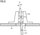
- Figure 8 shows a guide 250 temporarily attached to the break disc 46 for introducing the longitudinal support 220 and the plurality of sensors 210 to be attached to the rotor 30 through an inspection hole 47 of the break disc 46.
- the longitudinal support 220 is inserted through the guide 250 and the inspection hole 47 of the break disc 46 and mounted on the rotor 30 with an angle of inclination ⁇ , which may be comprised between 0 and 10 degrees with respect to the rotational axis Y.
- the angle of inclination ⁇ depends on the geometrical constraints of the assembly including the stator 20 and the rotor 30.
- the break disc 46 is not mounted when the longitudinal support 220 is to be coupled to the rotor 30, for example during the first step 101 in the second embodiment ( figure 4 ) of the method 100.
- another component of the electric generator 11 may be used for mounting the guide 250.
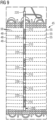
- Figures 9 and 10 show more in detail, with respect to fig. 5 , the coupling between a plurality of sensors 210 fixed on the longitudinal support 220 and a segment 45 of the stator 20.
- the segment 45 comprises a plurality of segment axial portions 48 which are arrayed along the longitudinal or rotational axis Y.
- the segment axial portions 48 are separated from each other by air ducts 55 for letting a cooling fluid flow in the air duct 55.
- Each segment axial portion 48 may be formed of a plurality of laminations stacked along the longitudinal axis Y to form the segment 45.
- the lamination stack is discontinued, and a plurality of spacers 56 are provided in the air duct 55 between the two respective and axially adjacent segment axial portions 48.
- the measurement device 200 comprises one or more threads 225 (six threads 225 in the embodiment shown in fig. 9 ), each thread 225 extending through a respective air duct 55.
- the thread 225 grasps the longitudinal support 220 and is tightened in such a way that the longitudinal support 220 is pushed against the external side of the stator segment 45 ( fig. 9 ).
- a respective thread tightener 226 is provided to tighten the thread 225.
- the thread 225 may be made on nylon or other similar material. According to other embodiments of the invention, threads 225 may be used to to fix the longitudinal support 220 to the rotor 30.
- Figures 11 to 13 show the coupling between a plurality of sensors 210 fixed on the longitudinal support 220 and the rotor 30.
- An under-pressure is applied to the longitudinal support 220 to fix the longitudinal support 220 on a respective magnet 31.
- an under-pressure may be applied to the longitudinal support 220 to fix the longitudinal support 220 on a respective surface of the rotor facing the air gap 15.
- the under-pressure is applied by means of an under-pressure device 227 having an under-pressure generator 228 connected to an air cable 229 ( fig. 11 ).
- the longitudinal support 220 to be coupled to be attached to the rotor 30 may comprise to such purpose a channel to be coupled to under-pressure generator 228 via the air cable 229, the channel 221 having an opening 231 surrounded by a sealing 232 to be attached to a respective magnet 31.
- the opening 231 is provided on the surface of the longitudinal support 220 which is subject to contact the magnet 31 in operation (therefore the opening 231 is not visible in Fig. 12 , but it is shown in Fig. 13 ).
- the under-pressure generator 228 When the under-pressure generator 228 is activated, air can be evacuated from the opening 231 towards the air cable 229, thus generating the under-pressure which pushes the opening 231 of the longitudinal support 220 towards the respective magnet 31.
- an under-pressure may be applied to the longitudinal support 220 to fix the longitudinal support 220 to the stator 20.
Landscapes
- Engineering & Computer Science (AREA)
- Physics & Mathematics (AREA)
- General Physics & Mathematics (AREA)
- Life Sciences & Earth Sciences (AREA)
- Sustainable Development (AREA)
- Sustainable Energy (AREA)
- Chemical & Material Sciences (AREA)
- Combustion & Propulsion (AREA)
- Mechanical Engineering (AREA)
- General Engineering & Computer Science (AREA)
- Length Measuring Devices With Unspecified Measuring Means (AREA)
Description
- The invention relates to a method and a device for measuring the airgap between the stator and the rotor of an electric generator. Particularly, but not exclusively, can be applied to an electric generator for a wind turbine.
- The airgap, which is formed between the stator and a rotor in a wind turbine electric generator is an important design feature that contributes to determines the overall efficiency of the wind turbine. The tighter the airgap is and the less it fluctuates over the lateral surfaces the axial ends of the stator and the rotor, the more energy can be generated and the higher the efficiency is. During the assembly process of the electric generator, it is known to measure the airgap after the pairing between stator and rotor. The airgap has normally a thickness in the range of some millimetres and is therefore not well accessible. Nevertheless, the production must record the values as part of the quality check. Furthermore, the airgap measurement is possibly provided to the customer as a critical quality reference in the future.
- This measurement may be performed manually by technicians, who have to crawl into the inside of the stator and use calliper gauges that are applied through radial airducts in the stator segments to measure the airgap. Multiple measurements are performed along the circumference of the generator. This procedure implies a plurality of inconveniences, for example:
- low accuracy of the measurements because the manual application is error prone. The repeatability accounts for a large error in the total measurement,
- low number of measurement points lead to an imprecise measurement of the airgap in height as well as circumference direction,
- long times required for performing the measurement operations.
- The document
DE102016122862 A1 discloses a method for performing a plurality of measurements in the air gap between a stator and a rotor of a generator for a wind turbine according to the state of the art. - It may be therefore an object of the present invention to provide a method and a device for measuring the airgap between the stator and the rotor of an electric generator, which overcomes the above-mentioned inconveniences of the prior art.
- This object may be solved by a method and a device according to the subject matter of the independent claims. Advantageous embodiments of the present invention are described by the dependent claims.
- One aspect of the invention relates to a method for performing a plurality of measurements in the air gap between a stator and a rotor of a generator for a wind turbine, the rotor being rotatable with respect to the stator about a rotational axis, the method including the steps of:
- mounting a plurality of distance measuring sensors on at least one surface of the stator and/or the rotor, said surface facing the air gap, each distance measuring sensor being distanced from the other distance measuring sensor(s) along rotational axis,
- rotating the rotor about the rotational axis,
- while rotating the rotor, measuring a plurality of distances between each of said distance measuring sensors (110) and respective facing points across the air gap,
- deriving from said plurality of distances one or more value(s) of one or more parameter(s) associated with the air gap and/or the stator and/or rotor,
- wherein at least a portion of plurality of distance measuring sensors are fixed to a longitudinal support, said longitudinal support being fixed on a surface of the stator and/or the rotor, said surface facing the air gap, during said step of mounting.
- According to possible embodiments of the invention, said one or more parameter(s) associated with the air gap may be any of:
- a thickness of the air gap, and/or
- a rotor roundness, and/or
- a stator roundness, and/or
- a rotor concentricity, and/or
- a stator concentricity, and/or
- distance of the rotor center from a reference position, and/or
- distance of the stator center from a reference position.
- The present invention permits to achieve the following advantages:
- accuracy of the measurement by reducing the risk of manual application errors and a high degree of repeatability,
- great number of measurement points so that an envelope of the entire airgap can be compiled,
- attaching, measuring and detaching the system requires low manual effort and is faster than current measurements
- It is further possible that the nominal airgap may be reduced in turbine generations due to higher confidence of the airgap, due to the above-described measurement procedure. The production can fulfill quality assurance step faster, with higher data accuracy in less manual work (faster process). It also supports to understand assembly factors better how they impact the airgap and thus optimize the assembly to achieve an optimal airgap.
- According to a possible embodiment of the invention, said steps of mounting rotating and measuring are first performed with the plurality of distance measuring sensors mounted on one of the stator and rotor and then said steps of mounting rotating and measuring are again performed with the plurality of distance measuring sensors (110) mounted on the other of rotor and stator.
- According to another possible embodiment of the invention, in said step of mounting a first plurality of distance measuring sensors are mounted on a first surface of the stator and a second plurality of distance measuring sensors are mounted on a second surface of the rotor, said first and second surfaces facing the air gap.
- According to possible embodiments of the invention, at least a portion of plurality of distance measuring sensors are fixed to a longitudinal support, said longitudinal support being fixed on a surface of the stator and/or the rotor, said surface facing the air gap, during said step of mounting.
- Another aspect of the invention relates to a measurement device for performing a plurality of measurements in the air gap between a stator and a rotor of a generator for a wind turbine, the measurement device including:
- a plurality of distance measuring sensors mounted on a longitudinal support,
- a controller connected to the plurality of distance measuring sensors and configured for deriving from a plurality of distances measured by the sensors one or more value(s) of one or more parameter(s) associated with the air gap and/or the stator and/or rotor, when the steps of the measurement method above described are being performed.
- According to possible embodiments of the invention, the longitudinal support may be in form of a stick along which the plurality of sensors is attached. The sensors may be regularly distributed along the length of the longitudinal support. The longitudinal support may be oriented during the measurement operations along the rotational axis of the electric generator or inclined with respect thereto of an inclination angle comprised between 0 and 10 degree. Such inclination angle may depend on the geometric constraints of the stator and/or rotor. The longitudinal support with the plurality of sensors may be fixed during the measurement operations to a surface of the stator or to a surface of the rotor, such surfaces of the stator and the rotor facing the airgap. In electric generators where the rotor is radial external to the stator, the longitudinal support with the plurality of sensors may be fixed during the measurement operations to an external surface of the stator or to an internal surface of the rotor. In electric generators where the rotor is radial internal to the stator, the longitudinal support with the plurality of sensors may be fixed during the measurement operations to an external surface of the rotor or to an internal surface of the stator. In permanent magnet electric generators, the longitudinal support with the plurality of sensors may be fixed to one or more magnets facing the airgap.
- According to possible embodiments of the invention, the measurement device may include two longitudinal supports to be respectively fixed during the measurement operations to a surface of the stator and to a surface of the rotor, such surfaces of the stator and the rotor facing the airgap.
- According to possible embodiments of the invention, the longitudinal support with the plurality of sensors may be fixed at positions, which are radially distanced from the airgap.
- According to possible embodiments of the invention, the plurality of distance measuring sensors are capacitive sensors. The sensors may be capacitive film sensors or capacitive flat sensors. The sensors may be capacitive tactile sensor or eddy current sensors.
- According to possible embodiments of the invention, the longitudinal support is fixed to the stator or the rotor by means of at least one thread or similar thin material. Each thread may grasp the longitudinal support and extend through a respective air duct of the stator, the thread being tightened in such a way that the longitudinal support is pushed against the external side of the stator. Such embodiments permit a strong fixation of the longitudinal support onto the stator surface. The fixing procedure is characterized by easy handability with tightening, removability without destroying materials and reusability.
- According to possible embodiments of the invention, the longitudinal support is fixed to the stator or the rotor by applying un under-pressure between the longitudinal support and a surface of the stator or the rotor facing the air gap, the under-pressure pushing the longitudinal support towards the surface of the stator or the rotor facing the air gap. In such embodiments, the longitudinal support may comprise a channel having an opening to be attached to a surface of the rotor facing the air gap, the measurement device comprising an under-pressure generator to be connected to the channel for evacuating air is activated, air can be evacuated from the opening. Fixing by applying under-pressure allows secure and strong fixation of the longitudinal support onto a rotor surface, e.g. a magnet surface. Removability without destroying materials and reusability can be achieved. A thin design is possible for adapting to the tight space conditions in the airgap.
- It should be understood that features, which have individually or in any combination been disclosed for a method for performing a plurality of measurements in the air gap between a stator and a rotor of a generator for a wind turbine, may also, individually or in any combination, be provided for a measurement device according to embodiments of the present invention and vice versa.
- The aspects defined above and further aspects of the present invention are apparent from the examples of embodiment to be described hereinafter and are explained with reference to the examples of embodiment. The invention will be described in more detail hereinafter with reference to examples of embodiment but to which the invention is not limited.
-
- Figure 1
- shows a schematic section of a wind turbine including an electric generator.
- Figure 2
- shows an exploded view of the stator and rotor of the electric generator of
figure 1 . - Figure 3
- shows a block diagram illustrating a first embodiment of a measurement method according to the present invention for performing a plurality of measurements in the air gap of the electric generator of
figures 1 and2 . - Figure 4
- shows a block diagram illustrating a second embodiment of a measurement method according to the present invention for performing a plurality of measurements in the air gap of the electric generator of
figures 1 and2 . - Figure 5
- shows a partial view of an assembly of the stator of the electric generator of
figures 1 and2 and a measurement device according to the present invention. - Figure 6
- shows a partial view of an assembly of the electric generator of
figures 1 and2 and a measurement device according to the present invention. - Figure 7
- shows a step of the measurement method of the present invention illustrating the fixing of the measurement device to the rotor of the electric generator.
- Figure 8
- shows a more detailed view of the step of the measurement method of
figure 7 . - Figure 9
- shows a partial front view of an assembly of the stator of the electric generator of
figures 1 and2 , a measurement device according to the present invention and means for fixing the measurement device to the stator. - Figure 10
- shows a rear partial view of the assembly of
figure 9 . - Figure 11
- shows a partial front view of an assembly of the rotor of the electric generator of
figures 1 and2 , a measurement device according to the present invention and means for fixing the measurement device to the rotor. - Figure 12
- shows more in detail the assembly of the rotor of the electric generator of
figures 1 and2 and of the measurement device according to the present invention. - Figure 13
- shows means for fixing the measurement device according to the present invention to the rotor.
- The illustrations in the drawings are schematic. It is noted that in different figures, similar or identical elements are provided with the same reference signs.
-
Figure 1 shows awind turbine 1 according to the invention. Thewind turbine 1 comprises atower 2, which is mounted on a non-depicted foundation. Anacelle 3 is arranged on top of thetower 2. Thewind turbine 1 further comprises at least awind rotor 5 having a hub and at least one blade 4 (in the embodiment ofFigure 1 , the wind rotor comprises threeblades 4, of which only twoblades 4 are visible). Thewind rotor 5 is rotatable around a rotational longitudinal axis Y. Theblades 4 extend substantially radially with respect to the longitudinal rotational axis Y. In general, when not differently specified, the terms axial, radial and circumferential in the following are made with reference to the longitudinal rotational axis Y. Thewind turbine 1 comprises at least oneelectric generator 11, including astator 20 and arotor 30. Therotor 30 is rotatable with respect to thestator 20 about the longitudinal rotational axis Y. Thewind rotor 5 is coupled with therotor 30, in order to rotate about the rotational longitudinal axis Y. Theelectric generator 11 comprise anairgap 15 radially interposed between thestator 20 and therotor 30, theairgap 15 extending circumferentially about the rotational axis Y. In the embodiment of the attached figures therotor 30 is radially external to thestator 20. According to other embodiments (not show), the rotor may be radially internal to the stator. -
Figure 2 shows an exploded view of theelectrical generator 11 with therotor 30 and thestator 20. Thestator 20 comprises a cylindrical inner core to which sixsegments 45 are attached. Eachsegment 45 has a circumferential angular extension of 60°. According to other embodiments of the present invention, thestator 20 comprises a plurality of segments having a number of segments different from six. According to another possible embodiment of the present invention, thestator 20 is not segmented, i.e. the stator includes one single segment covering the entire angular extension of 360°. Therotor 30 has a conventional structure with a plurality of circumferentially distributed rotorpermanent magnets 31. Themagnets 31 are distributed on an inner side of therotor 30 according to axial columns. Each column of magnets comprises a plurality of magnets 31 (twomagnets 31 in the embodiment offigure 2 ) aligned along the rotational axis Y. -
Figures 3 and 4 show two respective block diagram of amethod 100 for performing a plurality of measurements in theair gap 15. Such method may be performed during the manufacturing of the electric generator, for example as quality check. - A
method 100 for performing a plurality of measurements in theair gap 15 includes the following steps: - a
first step 101 of mounting a plurality ofdistance measuring sensors 210 on at least one respective surface of thestator 20 and/or therotor 30. The surface(s) face theair gap 15, eachdistance measuring sensor 210 being distanced from the other distance measuring sensor(s) 210 along the rotational axis Y, - a
second step 102 of rotating therotor 30 about the rotational axis Y, - a
third step 103 of, while rotating therotor 30, measuring a plurality of distances between each of saiddistance measuring sensors 210 and respective facing points across theair gap 15, - a
fourth step 104 of data analysis for deriving from the plurality of measured distances one or more value(s) of one or more parameter(s) associated with theair gap 15 and/or thestator 20 and/orrotor 30. - Such parameter(s) associated with the
air gap 15 may be one or more of: - a thickness of the air gap,
- a rotor roundness,
- a stator roundness,
- a rotor concentricity,
- a stator concentricity,
- distance of the rotor center from a reference position,
- distance of the stator center from a reference position.
-
Figure 3 shows a first embodiment of a block diagram of amethod 100. In a first execution of thefirst step 101, themethod 100 comprises mounting a plurality ofdistance measuring sensors 210 on a surface of thestator 20 facing the air gap 15 (figure 5 and6 ). For example, thesensors 210 may be attached to an external surface of astator segment 45. The plurality of distance measuring sensors 110 may be alternatively mounted on a surface of therotor 30 facing theair gap 15. Thesensors 210 are fixed to thestator 20 orrotor 30 in such a way that eachdistance measuring sensor 210 is distanced from the otherdistance measuring sensors 210 along the rotational axis Y. After thefirst step 101 therotor 30 and thestator 20 are paired and a break disc 46 (shown infigure 6 and 7 ) is attached to thegenerator 11. In a first execution of thesecond step 102 themethod 100 comprises rotating therotor 30 about the rotational axis Y. A complete rotation of 360 degrees or more may be executed. The rotation of therotor 30 is initiated and stopped by an external device. In a first execution of thethird step 103 of themethod 100 comprises, while rotating therotor 30, measuring a first plurality of distances between each of thedistance measuring sensors 210, which has been mounted during thefirst step 101 of the method, and respective facing points across theair gap 15. After thethird step 103 thesensors 210, which have been mounted during the first execution of thefirst step 101, are removed. Thefirst step 101 of themethod 100 is then repeated mounting the same or another plurality ofdistance measuring sensors 210 on a surface of therotor 30 facing the air gap 15 (figure 7 ). For example, thesensors 210 may be attached to themagnets 31. The plurality of distance measuring sensors 110 may be alternatively mounted on a surface of thestator 20 facing theair gap 15, if in the previous execution of thefirst step 101distance measuring sensors 210 were mounted on therotor 30. A second execution of thesecond step 102 andthird step 103 is also performed for measuring a second plurality of distances by means of thedistance measuring sensors 210. After thethird step 103 thesensors 210, which have been mounted during the second execution of thefirst step 101, are removed and the finalfourth step 104 is performed. -
Figure 4 shows a second embodiment of a block diagram of amethod 100. In thefirst step 101, themethod 100 comprises mounting a first plurality ofdistance measuring sensors 210 on a surface of thestator 20 facing the air gap 15 (figure 5 ). For example, thesensors 210 may be attached to an external surface of astator segment 45. Therotor 30 and thestator 20 are then paired. In thefirst step 101, themethod 100 further comprises mounting a second plurality of distance measuring sensors 110 on a surface of therotor 30 facing theair gap 15. For example, thesensors 210 may be attached to themagnets 31. Thesensors 210 are fixed to thestator 20 androtor 30 in such a way that eachdistance measuring sensor 210 is distanced from the otherdistance measuring sensors 210 along the rotational axis Y. After that thebreak disc 46 is attached to thegenerator 11. Thesecond step 102 of themethod 100 is executed by rotating therotor 30 about the rotational axis Y. A complete rotation of 360 degrees or more may be executed. The rotation of therotor 30 is initiated and stopped by an external device. Thethird step 103 of themethod 100 is then executed, while rotating therotor 30, for measuring a plurality of distances between each of thedistance measuring sensors 210, which has been mounted during thefirst step 101 of the method, and respective facing points across theair gap 15. The plurality of distances measured during thethird step 103 includes the measurement performed with the first plurality ofsensors 210 and the second plurality ofsensors 210 installed during thefirst step 101. After thethird step 103 thesensors 210 are removed and the finalfourth step 104 is performed. -
Figure 5 shows the coupling between a plurality ofsensors 210 and asegment 45 of thestator 20, performed during thefirst step 101 of themethod 100. Thedistance measuring sensors 210 are comprised in ameasurement device 200, which also includes alongitudinal support 220, for example a stick, on which thesensors 210 are fixed and acontroller 230 connected to the plurality ofdistance measuring sensors 210, for example by means of a cable 240, and configured for performing the steps of themethod 100. Themeasurement device 200 offigure 5 includes sixdistance measuring sensors 210. According to other embodiments (not shown), themeasurement device 200 offigure 5 may include two or moredistance measuring sensors 210. The measuringsensors 210 may be capacitive sensors. For example, the measuringsensors 210 may be capacitive film sensors or capacitive flat sensors. According to other embodiments (not shown), thelongitudinal support 220 may include one or more cable ties, screws, rubber bands, a knee-lever system or similar. Thelongitudinal support 220 may be tightened on the outer surface of thesegment 45 with any tightening means. -
Figure 6 shows the pairing between thestator 20 and therotor 30 and the mounting of thebreak disc 46, performed after the first execution of thestep 101 in the first embodiment (figure 3 ) of themethod 100. -
Figure 7 shows the coupling between a plurality ofsensors 210 and therotor 30, performed during the second execution of thefirst step 101 in the first embodiment (figure 3 ) of themethod 100. Thedistance measuring sensors 210 are comprised in thesame measurement device 200 used during the first execution of the step 101 (fig. 5 ) or in anothermeasurement device 200. In other to facilitate the coupling between the measuringsensors 210 and themagnets 31, thelongitudinal support 220 comprises a metallic material that has low magnetic properties. The length of thelongitudinal support 220 may be in the range of some. A correct positioning may therefore require a guide for thelongitudinal support 220. -
Figure 8 shows aguide 250 temporarily attached to thebreak disc 46 for introducing thelongitudinal support 220 and the plurality ofsensors 210 to be attached to therotor 30 through aninspection hole 47 of thebreak disc 46. Thelongitudinal support 220 is inserted through theguide 250 and theinspection hole 47 of thebreak disc 46 and mounted on therotor 30 with an angle of inclination α, which may be comprised between 0 and 10 degrees with respect to the rotational axis Y. the angle of inclination α depends on the geometrical constraints of the assembly including thestator 20 and therotor 30. - According to other embodiments (not shown), the
break disc 46 is not mounted when thelongitudinal support 220 is to be coupled to therotor 30, for example during thefirst step 101 in the second embodiment (figure 4 ) of themethod 100. In such case another component of theelectric generator 11 may be used for mounting theguide 250. -
Figures 9 and10 show more in detail, with respect tofig. 5 , the coupling between a plurality ofsensors 210 fixed on thelongitudinal support 220 and asegment 45 of thestator 20. Thesegment 45 comprises a plurality of segmentaxial portions 48 which are arrayed along the longitudinal or rotational axis Y. The segmentaxial portions 48 are separated from each other byair ducts 55 for letting a cooling fluid flow in theair duct 55. Each segmentaxial portion 48 may be formed of a plurality of laminations stacked along the longitudinal axis Y to form thesegment 45. At eachair duct 55 the lamination stack is discontinued, and a plurality ofspacers 56 are provided in theair duct 55 between the two respective and axially adjacent segmentaxial portions 48. Themeasurement device 200 comprises one or more threads 225 (sixthreads 225 in the embodiment shown infig. 9 ), eachthread 225 extending through arespective air duct 55. Thethread 225 grasps thelongitudinal support 220 and is tightened in such a way that thelongitudinal support 220 is pushed against the external side of the stator segment 45 (fig. 9 ). On the opposite internal side of stator segment 45 (fig. 10 ) arespective thread tightener 226 is provided to tighten thethread 225. Thethread 225 may be made on nylon or other similar material. According to other embodiments of the invention,threads 225 may be used to to fix thelongitudinal support 220 to therotor 30. -
Figures 11 to 13 show the coupling between a plurality ofsensors 210 fixed on thelongitudinal support 220 and therotor 30. An under-pressure is applied to thelongitudinal support 220 to fix thelongitudinal support 220 on arespective magnet 31. According to other embodiments of the invention, an under-pressure may be applied to thelongitudinal support 220 to fix thelongitudinal support 220 on a respective surface of the rotor facing theair gap 15. The under-pressure is applied by means of an under-pressure device 227 having an under-pressure generator 228 connected to an air cable 229 (fig. 11 ). Thelongitudinal support 220 to be coupled to be attached to therotor 30 may comprise to such purpose a channel to be coupled to under-pressure generator 228 via theair cable 229, thechannel 221 having anopening 231 surrounded by a sealing 232 to be attached to arespective magnet 31. Theopening 231 is provided on the surface of thelongitudinal support 220 which is subject to contact themagnet 31 in operation (therefore theopening 231 is not visible inFig. 12 , but it is shown inFig. 13 ). When the under-pressure generator 228 is activated, air can be evacuated from theopening 231 towards theair cable 229, thus generating the under-pressure which pushes theopening 231 of thelongitudinal support 220 towards therespective magnet 31. According to other embodiments of the invention, an under-pressure may be applied to thelongitudinal support 220 to fix thelongitudinal support 220 to thestator 20.
Claims (7)
- A method for performing a plurality of measurements in the air gap (15) between a stator (20) and a rotor (30) of a generator (11) for a wind turbine (1), the rotor (30) being rotatable with respect to the stator (20) about a rotational axis (Y), the method including the steps of:mounting a plurality of distance measuring sensors (210) on at least one surface of the stator (20) and/or the rotor (30), said surface facing the air gap (15), each distance measuring sensor (210) being distanced from the other distance measuring sensor(s) (210) along the rotational axis (Y),rotating the rotor (30) about the rotational axis (Y),while rotating the rotor (30), measuring a plurality of distances between each of said distance measuring sensors (210) and respective facing points across the air gap (15),deriving from said plurality of distances one or more value(s) of one or more parameter(s) associated with the air gap (15) and/or the stator (20) and/or rotor (30), characterized in that at least a portion of plurality of distance measuring sensors (210) are fixed to a longitudinal support (220), said longitudinal support (220) being fixed on a surface of the stator (20) and/or the rotor (30), said surface facing the air gap (15), during said step of mounting.
- The method according to claim 1, wherein said steps of mounting, rotating and measuring are first performed with the plurality of distance measuring sensors (210) mounted on one of the stator (20) and rotor (30) and then said steps of mounting, rotating and measuring are again performed with the plurality of distance measuring sensors (210) mounted on the other of the rotor (30) and stator (20).
- The method according to claim 1, wherein in said step of mounting a first plurality of distance measuring sensors (210) are mounted on a first surface of the stator (20) and a second plurality of distance measuring sensors (210) are mounted on a second surface of the rotor (30), said first and second surfaces facing the air gap (15).
- The method according to claim 1, wherein the longitudinal support (220) is mounted with an angle of inclination (α) comprised between 0 and 10 degrees with respect to the rotational axis (Y).
- The method according to any of the previous claims, wherein said one or more parameter(s) associated with the air gap (15) is any of:a thickness of the air gap, and/ora rotor roundness, and/ora stator roundness, and/ora rotor concentricity, and/ora stator concentricity, and/ordistance of the rotor center from a reference position, and/ordistance of the stator center from a reference position.
- A measurement device (200) for performing a plurality of measurements in the air gap (15) between a stator (20) and a rotor (30) of a generator (11) for a wind turbine (1), the measurement device (200) including:a plurality of distance measuring sensors (210) mounted on a longitudinal support (220),a controller (230) connected to the plurality of distance measuring sensors (210) and configured for deriving from a plurality of distances measured by the sensors (210) one or more value(s) of one or more parameter(s) associated with the air gap (15) and/or the stator (20) and/or rotor (30), when the steps of the method according to any of the previous claims are being performed.
- The measurement device (200) according to claim 6, wherein the plurality of distance measuring sensors (210) are capacitive sensors.
Applications Claiming Priority (2)
| Application Number | Priority Date | Filing Date | Title |
|---|---|---|---|
| EP20212662.9A EP4012327A1 (en) | 2020-12-09 | 2020-12-09 | Airgap measurement in a generator of a wind turbine |
| PCT/EP2021/083616 WO2022122482A1 (en) | 2020-12-09 | 2021-11-30 | Airgap measurement in a generator of a wind turbine |
Publications (2)
| Publication Number | Publication Date |
|---|---|
| EP4226116A1 EP4226116A1 (en) | 2023-08-16 |
| EP4226116B1 true EP4226116B1 (en) | 2024-09-25 |
Family
ID=73789869
Family Applications (2)
| Application Number | Title | Priority Date | Filing Date |
|---|---|---|---|
| EP20212662.9A Ceased EP4012327A1 (en) | 2020-12-09 | 2020-12-09 | Airgap measurement in a generator of a wind turbine |
| EP21823838.4A Active EP4226116B1 (en) | 2020-12-09 | 2021-11-30 | Airgap measurement in a generator of a wind turbine |
Family Applications Before (1)
| Application Number | Title | Priority Date | Filing Date |
|---|---|---|---|
| EP20212662.9A Ceased EP4012327A1 (en) | 2020-12-09 | 2020-12-09 | Airgap measurement in a generator of a wind turbine |
Country Status (5)
| Country | Link |
|---|---|
| US (1) | US20240011757A1 (en) |
| EP (2) | EP4012327A1 (en) |
| CN (1) | CN116670465A (en) |
| DK (1) | DK4226116T3 (en) |
| WO (1) | WO2022122482A1 (en) |
Families Citing this family (1)
| Publication number | Priority date | Publication date | Assignee | Title |
|---|---|---|---|---|
| KR20250125196A (en) * | 2024-02-14 | 2025-08-21 | 두산에너빌리티 주식회사 | Apparatus for measuring wind power generator air gap |
Family Cites Families (10)
| Publication number | Priority date | Publication date | Assignee | Title |
|---|---|---|---|---|
| DE19961528C1 (en) * | 1999-12-20 | 2001-06-13 | Siemens Ag | Radial gap monitoring method especially for radial gap between rotor and stator of electric generator |
| US7581921B2 (en) * | 2006-06-19 | 2009-09-01 | General Electric Company | Methods and apparatus for controlling rotary machines |
| US7891938B2 (en) * | 2007-03-20 | 2011-02-22 | General Electric Company | Multi sensor clearance probe |
| EP2517339A1 (en) * | 2010-03-03 | 2012-10-31 | Siemens Aktiengesellschaft | Method of attaching a magnet to a rotor or a stator of an electrical machine |
| US9154024B2 (en) * | 2010-06-02 | 2015-10-06 | Boulder Wind Power, Inc. | Systems and methods for improved direct drive generators |
| US20130300124A1 (en) * | 2012-05-11 | 2013-11-14 | Clipper Windpower, Inc. | Profiled Air Cap on Direct Drive Wind Turbine Generator |
| DE102016122862A1 (en) * | 2016-11-28 | 2018-05-30 | Wobben Properties Gmbh | Measuring system and a measuring method for measuring a stator of a gearless wind turbine |
| CN108418351B (en) * | 2018-01-12 | 2019-10-01 | 远景能源(江苏)有限公司 | Wind-driven generator air gap real-time detecting system and method |
| CN108494174B (en) * | 2018-04-09 | 2019-06-04 | 新疆金风科技股份有限公司 | Measurement of air gap device and wind power generating set |
| CN109341510B (en) * | 2018-10-31 | 2021-07-09 | 上海瑞视仪表电子有限公司 | Air gap measuring device of wind driven generator |
-
2020
- 2020-12-09 EP EP20212662.9A patent/EP4012327A1/en not_active Ceased
-
2021
- 2021-11-30 EP EP21823838.4A patent/EP4226116B1/en active Active
- 2021-11-30 WO PCT/EP2021/083616 patent/WO2022122482A1/en not_active Ceased
- 2021-11-30 DK DK21823838.4T patent/DK4226116T3/en active
- 2021-11-30 CN CN202180083357.9A patent/CN116670465A/en active Pending
- 2021-11-30 US US18/039,552 patent/US20240011757A1/en not_active Abandoned
Also Published As
| Publication number | Publication date |
|---|---|
| US20240011757A1 (en) | 2024-01-11 |
| EP4012327A1 (en) | 2022-06-15 |
| WO2022122482A1 (en) | 2022-06-16 |
| CN116670465A (en) | 2023-08-29 |
| DK4226116T3 (en) | 2024-11-11 |
| EP4226116A1 (en) | 2023-08-16 |
Similar Documents
| Publication | Publication Date | Title |
|---|---|---|
| US11489385B2 (en) | Rotor, rotary electric machine, and method for manufacturing rotor | |
| RU2551395C2 (en) | Method and device to inspect tightening of electric machine stator core | |
| US4633113A (en) | Side plate construction for permanent magnet rotor | |
| CA2832114C (en) | Method for assembling an electrical machine | |
| US6545467B1 (en) | Contoured surface eddy current inspection system | |
| EP2545252B1 (en) | Balance correction weight providing constant mass | |
| US7812495B2 (en) | Sleeve in end rings for permanent magnet rotor | |
| US20140021816A1 (en) | Wind turbine generator and maintenance of its main bearing | |
| US20030042818A1 (en) | System and method for end turn retention on a high speed generator rotor | |
| KR20180011189A (en) | How to construct a permanent magnet generator | |
| EP2575238A2 (en) | Rotor assembly | |
| JPH0638411A (en) | Generator | |
| CN101467330A (en) | Rotor for low inertia permanent magnet motor | |
| JP2012039807A (en) | Rotary electric machine, wind turbine generator system and method of manufacturing rotary electric machine | |
| US20240011757A1 (en) | Airgap measurement in a generator of a wind turbine | |
| JP7558523B2 (en) | Axial gap motor | |
| US4854034A (en) | Method for producing a stack of laminations with skewed conductor slots | |
| CN110023714A (en) | For measuring the measuring system and measurement method of the stator of the wind energy plant without transmission device | |
| US6629356B2 (en) | Method and apparatus for concentric assembly of structural rotor enclosure on an electrical machine rotor | |
| US4667148A (en) | Generator air-gap flux probe for detecting shorted rotor turns | |
| CN102655354B (en) | Rotor unit, power generating system, rotating motor, and generator, and assembly method for rotating motor | |
| JP2021521762A (en) | Winding type rotor for synchronous electromechanical machines | |
| US12149132B2 (en) | Segmented generator, generator segment and wind turbine, and also method for preparing transportation of a segmented generator, and for transporting and installing the same, and also method for assembling a wind turbine | |
| KR20150044471A (en) | Rotator for preventing breakaway thereof, Eletric motor having the same, and Method for manufacturing the same | |
| GB2388479A (en) | Permanent magnet rotor assembly suitable for mounting on a turbine shaft |
Legal Events
| Date | Code | Title | Description |
|---|---|---|---|
| STAA | Information on the status of an ep patent application or granted ep patent |
Free format text: STATUS: UNKNOWN |
|
| STAA | Information on the status of an ep patent application or granted ep patent |
Free format text: STATUS: THE INTERNATIONAL PUBLICATION HAS BEEN MADE |
|
| PUAI | Public reference made under article 153(3) epc to a published international application that has entered the european phase |
Free format text: ORIGINAL CODE: 0009012 |
|
| STAA | Information on the status of an ep patent application or granted ep patent |
Free format text: STATUS: REQUEST FOR EXAMINATION WAS MADE |
|
| 17P | Request for examination filed |
Effective date: 20230510 |
|
| AK | Designated contracting states |
Kind code of ref document: A1 Designated state(s): AL AT BE BG CH CY CZ DE DK EE ES FI FR GB GR HR HU IE IS IT LI LT LU LV MC MK MT NL NO PL PT RO RS SE SI SK SM TR |
|
| DAV | Request for validation of the european patent (deleted) | ||
| DAX | Request for extension of the european patent (deleted) | ||
| GRAP | Despatch of communication of intention to grant a patent |
Free format text: ORIGINAL CODE: EPIDOSNIGR1 |
|
| STAA | Information on the status of an ep patent application or granted ep patent |
Free format text: STATUS: GRANT OF PATENT IS INTENDED |
|
| INTG | Intention to grant announced |
Effective date: 20240506 |
|
| GRAS | Grant fee paid |
Free format text: ORIGINAL CODE: EPIDOSNIGR3 |
|
| GRAA | (expected) grant |
Free format text: ORIGINAL CODE: 0009210 |
|
| STAA | Information on the status of an ep patent application or granted ep patent |
Free format text: STATUS: THE PATENT HAS BEEN GRANTED |
|
| AK | Designated contracting states |
Kind code of ref document: B1 Designated state(s): AL AT BE BG CH CY CZ DE DK EE ES FI FR GB GR HR HU IE IS IT LI LT LU LV MC MK MT NL NO PL PT RO RS SE SI SK SM TR |
|
| REG | Reference to a national code |
Ref country code: GB Ref legal event code: FG4D |
|
| REG | Reference to a national code |
Ref country code: CH Ref legal event code: EP |
|
| REG | Reference to a national code |
Ref country code: DE Ref legal event code: R096 Ref document number: 602021019419 Country of ref document: DE |
|
| REG | Reference to a national code |
Ref country code: IE Ref legal event code: FG4D |
|
| REG | Reference to a national code |
Ref country code: DK Ref legal event code: T3 Effective date: 20241108 |
|
| REG | Reference to a national code |
Ref country code: NL Ref legal event code: FP |
|
| REG | Reference to a national code |
Ref country code: LT Ref legal event code: MG9D |
|
| PG25 | Lapsed in a contracting state [announced via postgrant information from national office to epo] |
Ref country code: NO Free format text: LAPSE BECAUSE OF FAILURE TO SUBMIT A TRANSLATION OF THE DESCRIPTION OR TO PAY THE FEE WITHIN THE PRESCRIBED TIME-LIMIT Effective date: 20241225 |
|
| PG25 | Lapsed in a contracting state [announced via postgrant information from national office to epo] |
Ref country code: GR Free format text: LAPSE BECAUSE OF FAILURE TO SUBMIT A TRANSLATION OF THE DESCRIPTION OR TO PAY THE FEE WITHIN THE PRESCRIBED TIME-LIMIT Effective date: 20241226 Ref country code: FI Free format text: LAPSE BECAUSE OF FAILURE TO SUBMIT A TRANSLATION OF THE DESCRIPTION OR TO PAY THE FEE WITHIN THE PRESCRIBED TIME-LIMIT Effective date: 20240925 |
|
| PG25 | Lapsed in a contracting state [announced via postgrant information from national office to epo] |
Ref country code: BG Free format text: LAPSE BECAUSE OF FAILURE TO SUBMIT A TRANSLATION OF THE DESCRIPTION OR TO PAY THE FEE WITHIN THE PRESCRIBED TIME-LIMIT Effective date: 20240925 |
|
| PG25 | Lapsed in a contracting state [announced via postgrant information from national office to epo] |
Ref country code: LV Free format text: LAPSE BECAUSE OF FAILURE TO SUBMIT A TRANSLATION OF THE DESCRIPTION OR TO PAY THE FEE WITHIN THE PRESCRIBED TIME-LIMIT Effective date: 20240925 |
|
| PG25 | Lapsed in a contracting state [announced via postgrant information from national office to epo] |
Ref country code: RS Free format text: LAPSE BECAUSE OF FAILURE TO SUBMIT A TRANSLATION OF THE DESCRIPTION OR TO PAY THE FEE WITHIN THE PRESCRIBED TIME-LIMIT Effective date: 20241225 |
|
| PG25 | Lapsed in a contracting state [announced via postgrant information from national office to epo] |
Ref country code: RS Free format text: LAPSE BECAUSE OF FAILURE TO SUBMIT A TRANSLATION OF THE DESCRIPTION OR TO PAY THE FEE WITHIN THE PRESCRIBED TIME-LIMIT Effective date: 20241225 Ref country code: NO Free format text: LAPSE BECAUSE OF FAILURE TO SUBMIT A TRANSLATION OF THE DESCRIPTION OR TO PAY THE FEE WITHIN THE PRESCRIBED TIME-LIMIT Effective date: 20241225 Ref country code: LV Free format text: LAPSE BECAUSE OF FAILURE TO SUBMIT A TRANSLATION OF THE DESCRIPTION OR TO PAY THE FEE WITHIN THE PRESCRIBED TIME-LIMIT Effective date: 20240925 Ref country code: GR Free format text: LAPSE BECAUSE OF FAILURE TO SUBMIT A TRANSLATION OF THE DESCRIPTION OR TO PAY THE FEE WITHIN THE PRESCRIBED TIME-LIMIT Effective date: 20241226 Ref country code: FI Free format text: LAPSE BECAUSE OF FAILURE TO SUBMIT A TRANSLATION OF THE DESCRIPTION OR TO PAY THE FEE WITHIN THE PRESCRIBED TIME-LIMIT Effective date: 20240925 Ref country code: BG Free format text: LAPSE BECAUSE OF FAILURE TO SUBMIT A TRANSLATION OF THE DESCRIPTION OR TO PAY THE FEE WITHIN THE PRESCRIBED TIME-LIMIT Effective date: 20240925 |
|
| REG | Reference to a national code |
Ref country code: AT Ref legal event code: MK05 Ref document number: 1726946 Country of ref document: AT Kind code of ref document: T Effective date: 20240925 |
|
| PG25 | Lapsed in a contracting state [announced via postgrant information from national office to epo] |
Ref country code: PT Free format text: LAPSE BECAUSE OF FAILURE TO SUBMIT A TRANSLATION OF THE DESCRIPTION OR TO PAY THE FEE WITHIN THE PRESCRIBED TIME-LIMIT Effective date: 20250127 Ref country code: IS Free format text: LAPSE BECAUSE OF FAILURE TO SUBMIT A TRANSLATION OF THE DESCRIPTION OR TO PAY THE FEE WITHIN THE PRESCRIBED TIME-LIMIT Effective date: 20250125 |
|
| PG25 | Lapsed in a contracting state [announced via postgrant information from national office to epo] |
Ref country code: SM Free format text: LAPSE BECAUSE OF FAILURE TO SUBMIT A TRANSLATION OF THE DESCRIPTION OR TO PAY THE FEE WITHIN THE PRESCRIBED TIME-LIMIT Effective date: 20240925 Ref country code: RO Free format text: LAPSE BECAUSE OF FAILURE TO SUBMIT A TRANSLATION OF THE DESCRIPTION OR TO PAY THE FEE WITHIN THE PRESCRIBED TIME-LIMIT Effective date: 20240925 |
|
| PG25 | Lapsed in a contracting state [announced via postgrant information from national office to epo] |
Ref country code: ES Free format text: LAPSE BECAUSE OF FAILURE TO SUBMIT A TRANSLATION OF THE DESCRIPTION OR TO PAY THE FEE WITHIN THE PRESCRIBED TIME-LIMIT Effective date: 20240925 |
|
| PG25 | Lapsed in a contracting state [announced via postgrant information from national office to epo] |
Ref country code: EE Free format text: LAPSE BECAUSE OF FAILURE TO SUBMIT A TRANSLATION OF THE DESCRIPTION OR TO PAY THE FEE WITHIN THE PRESCRIBED TIME-LIMIT Effective date: 20240925 Ref country code: AT Free format text: LAPSE BECAUSE OF FAILURE TO SUBMIT A TRANSLATION OF THE DESCRIPTION OR TO PAY THE FEE WITHIN THE PRESCRIBED TIME-LIMIT Effective date: 20240925 |
|
| PG25 | Lapsed in a contracting state [announced via postgrant information from national office to epo] |
Ref country code: PL Free format text: LAPSE BECAUSE OF FAILURE TO SUBMIT A TRANSLATION OF THE DESCRIPTION OR TO PAY THE FEE WITHIN THE PRESCRIBED TIME-LIMIT Effective date: 20240925 Ref country code: CZ Free format text: LAPSE BECAUSE OF FAILURE TO SUBMIT A TRANSLATION OF THE DESCRIPTION OR TO PAY THE FEE WITHIN THE PRESCRIBED TIME-LIMIT Effective date: 20240925 |
|
| PG25 | Lapsed in a contracting state [announced via postgrant information from national office to epo] |
Ref country code: IT Free format text: LAPSE BECAUSE OF FAILURE TO SUBMIT A TRANSLATION OF THE DESCRIPTION OR TO PAY THE FEE WITHIN THE PRESCRIBED TIME-LIMIT Effective date: 20240925 Ref country code: SK Free format text: LAPSE BECAUSE OF FAILURE TO SUBMIT A TRANSLATION OF THE DESCRIPTION OR TO PAY THE FEE WITHIN THE PRESCRIBED TIME-LIMIT Effective date: 20240925 |
|
| REG | Reference to a national code |
Ref country code: DE Ref legal event code: R097 Ref document number: 602021019419 Country of ref document: DE |
|
| REG | Reference to a national code |
Ref country code: CH Ref legal event code: PL |
|
| PG25 | Lapsed in a contracting state [announced via postgrant information from national office to epo] |
Ref country code: MC Free format text: LAPSE BECAUSE OF FAILURE TO SUBMIT A TRANSLATION OF THE DESCRIPTION OR TO PAY THE FEE WITHIN THE PRESCRIBED TIME-LIMIT Effective date: 20240925 |
|
| PG25 | Lapsed in a contracting state [announced via postgrant information from national office to epo] |
Ref country code: LU Free format text: LAPSE BECAUSE OF NON-PAYMENT OF DUE FEES Effective date: 20241130 |
|
| REG | Reference to a national code |
Ref country code: CH Ref legal event code: PL |
|
| PG25 | Lapsed in a contracting state [announced via postgrant information from national office to epo] |
Ref country code: CH Free format text: LAPSE BECAUSE OF NON-PAYMENT OF DUE FEES Effective date: 20241130 |
|
| PLBE | No opposition filed within time limit |
Free format text: ORIGINAL CODE: 0009261 |
|
| STAA | Information on the status of an ep patent application or granted ep patent |
Free format text: STATUS: NO OPPOSITION FILED WITHIN TIME LIMIT |
|
| REG | Reference to a national code |
Ref country code: BE Ref legal event code: MM Effective date: 20241130 |
|
| 26N | No opposition filed |
Effective date: 20250626 |
|
| PG25 | Lapsed in a contracting state [announced via postgrant information from national office to epo] |
Ref country code: SE Free format text: LAPSE BECAUSE OF FAILURE TO SUBMIT A TRANSLATION OF THE DESCRIPTION OR TO PAY THE FEE WITHIN THE PRESCRIBED TIME-LIMIT Effective date: 20240925 |
|
| PGFP | Annual fee paid to national office [announced via postgrant information from national office to epo] |
Ref country code: DK Payment date: 20250901 Year of fee payment: 5 |
|
| PG25 | Lapsed in a contracting state [announced via postgrant information from national office to epo] |
Ref country code: BE Free format text: LAPSE BECAUSE OF NON-PAYMENT OF DUE FEES Effective date: 20241130 |
|
| PGFP | Annual fee paid to national office [announced via postgrant information from national office to epo] |
Ref country code: GB Payment date: 20250901 Year of fee payment: 5 |
|
| PG25 | Lapsed in a contracting state [announced via postgrant information from national office to epo] |
Ref country code: IE Free format text: LAPSE BECAUSE OF NON-PAYMENT OF DUE FEES Effective date: 20241130 |
|
| PGFP | Annual fee paid to national office [announced via postgrant information from national office to epo] |
Ref country code: NL Payment date: 20251124 Year of fee payment: 5 |
|
| PGFP | Annual fee paid to national office [announced via postgrant information from national office to epo] |
Ref country code: DE Payment date: 20250829 Year of fee payment: 5 |
|
| PG25 | Lapsed in a contracting state [announced via postgrant information from national office to epo] |
Ref country code: HR Free format text: LAPSE BECAUSE OF FAILURE TO SUBMIT A TRANSLATION OF THE DESCRIPTION OR TO PAY THE FEE WITHIN THE PRESCRIBED TIME-LIMIT Effective date: 20240925 |
|
| PGFP | Annual fee paid to national office [announced via postgrant information from national office to epo] |
Ref country code: FR Payment date: 20251124 Year of fee payment: 5 |
|
| PG25 | Lapsed in a contracting state [announced via postgrant information from national office to epo] |
Ref country code: CY Free format text: LAPSE BECAUSE OF FAILURE TO SUBMIT A TRANSLATION OF THE DESCRIPTION OR TO PAY THE FEE WITHIN THE PRESCRIBED TIME-LIMIT; INVALID AB INITIO Effective date: 20211130 |