EP4225155B1 - Endoscopic resection assembly - Google Patents
Endoscopic resection assembly Download PDFInfo
- Publication number
- EP4225155B1 EP4225155B1 EP21802871.0A EP21802871A EP4225155B1 EP 4225155 B1 EP4225155 B1 EP 4225155B1 EP 21802871 A EP21802871 A EP 21802871A EP 4225155 B1 EP4225155 B1 EP 4225155B1
- Authority
- EP
- European Patent Office
- Prior art keywords
- pusher
- adaptor
- clip
- endoscopic
- tissue
- Prior art date
- Legal status (The legal status is an assumption and is not a legal conclusion. Google has not performed a legal analysis and makes no representation as to the accuracy of the status listed.)
- Active
Links
Images



Classifications
-
- A—HUMAN NECESSITIES
- A61—MEDICAL OR VETERINARY SCIENCE; HYGIENE
- A61B—DIAGNOSIS; SURGERY; IDENTIFICATION
- A61B17/00—Surgical instruments, devices or methods
- A61B17/32—Surgical cutting instruments
- A61B17/320016—Endoscopic cutting instruments, e.g. arthroscopes, resectoscopes
-
- A—HUMAN NECESSITIES
- A61—MEDICAL OR VETERINARY SCIENCE; HYGIENE
- A61B—DIAGNOSIS; SURGERY; IDENTIFICATION
- A61B17/00—Surgical instruments, devices or methods
- A61B17/32—Surgical cutting instruments
- A61B17/3205—Excision instruments
- A61B17/32056—Surgical snare instruments
-
- A—HUMAN NECESSITIES
- A61—MEDICAL OR VETERINARY SCIENCE; HYGIENE
- A61B—DIAGNOSIS; SURGERY; IDENTIFICATION
- A61B1/00—Instruments for performing medical examinations of the interior of cavities or tubes of the body by visual or photographical inspection, e.g. endoscopes; Illuminating arrangements therefor
- A61B1/00064—Constructional details of the endoscope body
- A61B1/00071—Insertion part of the endoscope body
- A61B1/0008—Insertion part of the endoscope body characterised by distal tip features
- A61B1/00087—Tools
-
- A—HUMAN NECESSITIES
- A61—MEDICAL OR VETERINARY SCIENCE; HYGIENE
- A61B—DIAGNOSIS; SURGERY; IDENTIFICATION
- A61B1/00—Instruments for performing medical examinations of the interior of cavities or tubes of the body by visual or photographical inspection, e.g. endoscopes; Illuminating arrangements therefor
- A61B1/00131—Accessories for endoscopes
- A61B1/0014—Fastening element for attaching accessories to the outside of an endoscope, e.g. clips, clamps or bands
-
- A—HUMAN NECESSITIES
- A61—MEDICAL OR VETERINARY SCIENCE; HYGIENE
- A61B—DIAGNOSIS; SURGERY; IDENTIFICATION
- A61B17/00—Surgical instruments, devices or methods
- A61B17/0057—Implements for plugging an opening in the wall of a hollow or tubular organ, e.g. for sealing a vessel puncture or closing a cardiac septal defect
-
- A—HUMAN NECESSITIES
- A61—MEDICAL OR VETERINARY SCIENCE; HYGIENE
- A61B—DIAGNOSIS; SURGERY; IDENTIFICATION
- A61B17/00—Surgical instruments, devices or methods
- A61B17/12—Surgical instruments, devices or methods for ligaturing or otherwise compressing tubular parts of the body, e.g. blood vessels or umbilical cord
- A61B17/122—Clamps or clips, e.g. for the umbilical cord
- A61B17/1227—Spring clips
-
- A—HUMAN NECESSITIES
- A61—MEDICAL OR VETERINARY SCIENCE; HYGIENE
- A61B—DIAGNOSIS; SURGERY; IDENTIFICATION
- A61B17/00—Surgical instruments, devices or methods
- A61B17/12—Surgical instruments, devices or methods for ligaturing or otherwise compressing tubular parts of the body, e.g. blood vessels or umbilical cord
- A61B17/128—Surgical instruments, devices or methods for ligaturing or otherwise compressing tubular parts of the body, e.g. blood vessels or umbilical cord for applying or removing clamps or clips
- A61B17/1285—Surgical instruments, devices or methods for ligaturing or otherwise compressing tubular parts of the body, e.g. blood vessels or umbilical cord for applying or removing clamps or clips for minimally invasive surgery
-
- A—HUMAN NECESSITIES
- A61—MEDICAL OR VETERINARY SCIENCE; HYGIENE
- A61B—DIAGNOSIS; SURGERY; IDENTIFICATION
- A61B17/00—Surgical instruments, devices or methods
- A61B17/00234—Surgical instruments, devices or methods for minimally invasive surgery
- A61B2017/00238—Type of minimally invasive operation
- A61B2017/00269—Type of minimally invasive operation endoscopic mucosal resection EMR
-
- A—HUMAN NECESSITIES
- A61—MEDICAL OR VETERINARY SCIENCE; HYGIENE
- A61B—DIAGNOSIS; SURGERY; IDENTIFICATION
- A61B17/00—Surgical instruments, devices or methods
- A61B17/00234—Surgical instruments, devices or methods for minimally invasive surgery
- A61B2017/00292—Surgical instruments, devices or methods for minimally invasive surgery mounted on or guided by flexible, e.g. catheter-like, means
- A61B2017/00296—Surgical instruments, devices or methods for minimally invasive surgery mounted on or guided by flexible, e.g. catheter-like, means mounted on an endoscope
-
- A—HUMAN NECESSITIES
- A61—MEDICAL OR VETERINARY SCIENCE; HYGIENE
- A61B—DIAGNOSIS; SURGERY; IDENTIFICATION
- A61B17/00—Surgical instruments, devices or methods
- A61B2017/00477—Coupling
-
- A—HUMAN NECESSITIES
- A61—MEDICAL OR VETERINARY SCIENCE; HYGIENE
- A61B—DIAGNOSIS; SURGERY; IDENTIFICATION
- A61B17/00—Surgical instruments, devices or methods
- A61B17/0057—Implements for plugging an opening in the wall of a hollow or tubular organ, e.g. for sealing a vessel puncture or closing a cardiac septal defect
- A61B2017/00575—Implements for plugging an opening in the wall of a hollow or tubular organ, e.g. for sealing a vessel puncture or closing a cardiac septal defect for closure at remote site, e.g. closing atrial septum defects
- A61B2017/00584—Clips
-
- A—HUMAN NECESSITIES
- A61—MEDICAL OR VETERINARY SCIENCE; HYGIENE
- A61B—DIAGNOSIS; SURGERY; IDENTIFICATION
- A61B17/00—Surgical instruments, devices or methods
- A61B2017/00831—Material properties
- A61B2017/0084—Material properties low friction
- A61B2017/00845—Material properties low friction of moving parts with respect to each other
-
- A—HUMAN NECESSITIES
- A61—MEDICAL OR VETERINARY SCIENCE; HYGIENE
- A61B—DIAGNOSIS; SURGERY; IDENTIFICATION
- A61B17/00—Surgical instruments, devices or methods
- A61B2017/00831—Material properties
- A61B2017/00902—Material properties transparent or translucent
- A61B2017/00907—Material properties transparent or translucent for light
-
- A—HUMAN NECESSITIES
- A61—MEDICAL OR VETERINARY SCIENCE; HYGIENE
- A61B—DIAGNOSIS; SURGERY; IDENTIFICATION
- A61B17/00—Surgical instruments, devices or methods
- A61B17/30—Surgical pincettes, i.e. surgical tweezers without pivotal connections
- A61B2017/306—Surgical pincettes, i.e. surgical tweezers without pivotal connections holding by means of suction
-
- A—HUMAN NECESSITIES
- A61—MEDICAL OR VETERINARY SCIENCE; HYGIENE
- A61B—DIAGNOSIS; SURGERY; IDENTIFICATION
- A61B90/00—Instruments, implements or accessories specially adapted for surgery or diagnosis and not covered by any of the groups A61B1/00 - A61B50/00, e.g. for luxation treatment or for protecting wound edges
- A61B90/03—Automatic limiting or abutting means, e.g. for safety
- A61B2090/037—Automatic limiting or abutting means, e.g. for safety with a frangible part, e.g. by reduced diameter
Definitions
- the present application is directed to devices used in surgical procedures, such as endoscopic procedures, and more particularly to endoscopic resection assemblies that can be connected to an endoscopic device.
- an endoscope includes a long flexible insertion tube having one or more channels through which miniaturized, flexible instruments can be inserted and advanced.
- the endoscope typically includes various optical features allowing for visualization of internal views of particular body parts, organs, or passages without requiring invasive surgery.
- the insertion tube may transmit images or image-producing signals from the illuminated operative site to a viewing means, providing the operator with full vision of the actions being performed at the working end of the endoscope.
- the operator first identifies a tissue such as a lesion in the digestive tract.
- the tissue is pulled into a cap provided on the endoscopic device via suction or other means.
- a clip is deployed over the tissue.
- a cutting device such as a snare cuts over the top of the clip, removing the tissue and leaving the clip closed over the otherwise open defect.
- the clip should be deployed before the cutting in order to pre-close the defect resulting from the cutting. Also, the clip should remain at the resection site until the body can heal itself.
- US5968056 relates generally to the field of tissue ligation, and more particularly to an improved device and method for electrosurgically severing lesions.
- US2014100423 relates to a method, a system and subsystems thereof for endoscopic full thickness resection surgical procedures, typically, but not necessarily, of the gastrointestinal (GI) tract.
- US2013172918 relates generally to systems and methods for resecting tissue, and more particularly, to systems for endoscopic mucosal resection.
- US2015230782 relates to a system for attaching devices to the distal end of endoscopic instruments.
- US2012010633 relates generally to devices and methods for securing inverted tissue, and more particularly, though not exclusively, to securing inverted diverticulum serosa to serosa.
- the present invention provides endoscopic resection assemblies for use in endoscopic procedures.
- the invention is defined by independent claim 1. Further embodiments are defined by the dependent claims. No surgical methods are claimed.
- the present invention provides an endoscopic resection assembly (100), comprising: (a) an adaptor (170), configured to couple to an endoscopic device; (b) a pusher (180), disposed on the adaptor (170); (c) at least one driver, configured to move the pusher (180) in a distal direction with respect to the adaptor (170); and (d) a cutting device (150), removably coupled to the pusher (180), wherein the cutting device (150) is configured to be removed from the pusher (180) when at least a portion of the pusher is distal to the adaptor (170), wherein the adaptor (170) is configured to be loaded with a clip (160), wherein the clip (160) is configured to operate between an open state and a closed state.
- the clip (160) is configured to be loaded on the adaptor (170) in the open state at a position distal to the pusher (180), wherein the clip (160) is configured to be pushed by the pusher (180) to slide off the distal edge (1701) of the adaptor (170) so that the clip (160) is configured to be released from the adaptor (170) and to engage onto a tissue before the cutting device (150) is removed from the pusher (180).
- the present invention can be used for cutting into or through the muscularis of the GI tract in order to remove dysplasia that has invaded past the mucosal layer of tissue.
- a clip can be deployed over the tissue prior to resection in order to pre-close the resulting defect created from the resection.
- an endoscopic resection assembly 100 includes an adaptor 170, a pusher 180, a cutting device 150, and a clip 160.
- the adaptor 170 is configured to attach to an endoscopic device.
- the pusher 180 is disposed on the adaptor 170 and configured to slide in the axial direction with respect to the adaptor 170.
- the cutting device 150 is an endoscopic tool for cutting a tissue, which operates between an open state and a closed state. As illustrated in FIGS. 3A and 3B , the cutting device 150 is removably coupled to the pusher 180.
- the clip 160 is an endoscopic tool configured to operate between an open state and a closed state, and is configured to engage onto a tissue. As illustrated in FIGS. 5A-5C , the clip 160 is loaded on the adaptor 170 in the open state at a position distal to the pusher 180.
- the endoscopic resection assembly 100 further includes at least one driver, controlled by an operator, configured to slide the pusher 180 in the distal direction with respect to the adaptor 170. As the pusher 180 slides in the distal direction with respect to the adaptor 170, the clip 160 is pushed by the pusher 180 to slide off the distal edge 1701 of the adaptor 170, and engages onto a tissue by reforming toward the closed state.
- the cutting device 150 can then be activated by the operator to detach from the pusher 180, and resect tissue above the pusher by operating toward the closed state.
- the endoscopic resection assembly 100 may include at least one driver and at least one sheath, a catheter 140, a clip deployment handle 190, and a handle 130.
- the at least one driver may comprise a first driver 121 and a second driver 122.
- the at least one sheath may comprise a first sheath 111 and a second sheath 112.
- the drivers may be directly adjacent to one another or spaced apart somewhat along the circumference of the pusher 180. For example, the drivers may be spaced about 10 degrees to 180 degrees, or about 15 degrees to 90 degrees, or about 30 degrees, apart from one another.
- FIG. 3B illustrates the assembly of the distal components of the endoscopic resection assembly 100, including the pusher 180, the cutting device 150, and the at least one driver.
- the cutting device 150 is an endoscopic tool for cutting a tissue, and operates between an open state and a closed state.
- the cutting device 150 has a snare drive cable 152 and a snare loop 154.
- the pusher 180 includes at least one retainer. As illustrated in FIG. 3B , the at least one retainer comprises the first retainer 183 and the second retainer 184, and retains the snare loop 154, such that the cutting device 150 is removably coupled to the pusher 180.
- the pusher 180 is driven by the at least one driver.
- the at least one driver comprises the first driver 121 and the second driver 122. The first driver 121 and the second driver 122 can be actuated to move the pusher 180 in the distal direction.
- the pusher 180 is disposed on the adaptor 170 and configured to slide in the axial direction with respect to the adaptor 170.
- the adaptor 170 may comprise a material to reduce friction and support movement of the pusher 180 and the clip 160. Suitable materials for the adaptor 170 include plastics such as polycarbonate, K-resin, acrylic, xylar, ASA, polypropylene, silicone, and TPES, or other similar materials.
- the adaptor 170 may comprise such plastics, or other materials, entirely or in part.
- the clip 160 is an endoscopic tool configured to operate between an open state and a closed state, and is configured to engage onto a tissue.
- the clip 160 is loaded on the adaptor in the open state at a position distal to the pusher 180.
- the pusher 180 and the clip 160 may not be secured together.
- the pusher 180 and the clip 160 may be secured together.
- one or more indents can be formed on the pusher 180
- one or more protrusions can be formed on the clip 160, where the one or more protrusions are configured to be secured into the one or more indents.
- the pusher 180 and the clip 160 can be secured together by other means such as welding, gluing, and overmolding.
- the snare drive cable 152 of the cutting device 150 extends within the catheter 140.
- the catheter 140 may be coupled with the adaptor 170.
- the at least one driver may respectively extend within the at least one sheath. As illustrated in FIG. 2C , the first driver 121 and the second driver 122 respectively extend within the first sheath 111 and the second sheath 112. The at least one sheath can be attached to the adaptor 170.
- the at least one driver can be actuated to move the pusher 180 in the distal direction.
- the pusher 180 slides in the distal direction with respect to the adaptor 170.
- the clip 160 is pushed by the pusher to slide off the distal edge 1701 of the adaptor 170, and engage onto a tissue by reverting to the closed state.
- the cutting device 150 can be activated to detach from the pusher 180, and cut a tissue by operating toward the closed state.
- the adaptor 170 has an inside surface and an outside surface.
- the adaptor 170 may include a lumen 173 and at least one overmolding.
- the at least one overmolding may comprise an overmolding 171 and an overmolding 172.
- the adaptor 170 may be substantially tubular with a distal open end and a proximal open end.
- the adaptor 170 may be hollow and define a tissue chamber channel.
- the adaptor 170 may be configured to attach with different types of endoscopic devices (e.g., Olympus ® , Fujinon ® , or Pentax ® endoscopes).
- endoscopic devices e.g., Olympus ® , Fujinon ® , or Pentax ® endoscopes.
- the inner and outer surface of the adaptor 170 may be contoured, and the inner and outer diameter of the adaptor 170 may be varied, in order to provide a good fit with the endoscopic device.
- the endoscopic device may be press-fitted to the proximal end of the adaptor 170.
- the adaptor 170 may comprise a flexible band, such as a rubber band, configured to be wrapped around the distal end of the endoscopic device.
- a person skilled in the art should understand that the shape of the adaptor 170 or the shape the tissue chamber channel can be any suitable shapes as long as it does not interfere with the operations of the endoscopic device.
- the tissue chamber channel may be configured to receive the tissue to be resected during resection operation.
- the adaptor 170 may be entirely or partially formed with materials sufficiently transparent to allow visualization of outside environment through various optical features from the inside of the adaptor 170. During resection operation, the sufficiently transparent materials may allow the operator to confirm whether the clip 160 is deployed, and observe the position of the cutting device 150 prior to tissue resection.
- the adaptor 170 is configured to allow the clip 160 and the pusher 180 to be disposed on the adaptor 170. As illustrated in FIGS. 5A-5C , the adaptor 170 is configured to allow the clip 160 and the pusher 180 to be disposed on the outside surface of the adaptor 170. The adaptor 170 is configured to allow the clip 160 and the pusher 180 to slide in the axial direction with respect to the adaptor 170. As illustrated in FIGS. 5A-5C , the outside surface of the adaptor 170 may be a smooth surface such that the clip 160 and the pusher 180 can slide in the axial direction with respect to the adaptor 170.
- the adaptor 170 may have any shape and may include any structural components, as long as the clip 160 and the pusher 180 can be disposed on the adaptor 170 and slide in the axial direction with respect to the adaptor 170.
- the adaptor 170 is configured to allow the clip 160 and/or the pusher 180 to be disposed on the inside surface of the adaptor 170.
- the adaptor 170 may include a support surface formed inside the adaptor 170, such that the clip 160 and/or the pusher 180 can be disposed on the support surface.
- the adaptor 170 can include one or more guide rails, such that the clip 160 and/or the pusher 180 are allowed to slide in the axial direction along the one or more guide rails.
- the adaptor 170 can include one or more longitudinal slits, such that the clip 160 and/or the pusher 180 are allowed to slide in the axial direction along the one or more longitudinal slits.
- the adaptor 170 may be configured to couple with the catheter 140. As illustrated in FIG. 2C , the adaptor 170 is coupled with the catheter 140 by inserting the catheter 140 into the lumen 173 of the adaptor 170.
- the lumen 173 may be formed on the outside surface of the adaptor 170, such that the catheter 140 is coupled with the outside surface of the adaptor 170.
- the lumen 173 may provide slip fit between the catheter 140 and the adaptor 170, such that the catheter 140 is allowed to freely slide in the axial direction with respect to the adaptor 170.
- the catheter 140 may be coupled to any portion of the adaptor 170, such as the inside surface of the adaptor 170, as long as the catheter 140 does not interfere with the operations of the endoscopic device and other components of the endoscopic resection assembly 100.
- the catheter 140 may penetrate the adaptor 170, such that the catheter 140 extends through a hole formed on the adaptor 170.
- the adaptor 170 can be fixed with the catheter 140, or be detached from the catheter 140, as long as the catheter 140 does not interfere with the operations of the endoscopic device and other components of the endoscopic resection assembly 100.
- the adaptor 170 may be configured to attach with the at least one sheath.
- the at least one sheath may comprise the first sheath 111 and the second sheath 112, and the first sheath 111 and the second sheath 112 may be attached to the adaptor 170 respectively by the overmolding 171 and the overmolding 172.
- the overmolding 171 and the overmolding 172 may be formed on the outside surface of the adaptor 170, such that the at least one sheath is attached to the outside surface of the adaptor 170.
- the at least one sheath can be attached with the adaptor 170 by other means, for example, friction, heat staking, gluing, or welding.
- the at least one sheath can be attached to any portion of the adaptor 170, such as the inside surface of the adaptor 170, as long as the at least one sheath does not interfere with the operations of the endoscopic device and other components of the endoscopic resection assembly 100.
- the at least one sheath may penetrate the adaptor 170, such that the at least one sheath extends through a hole formed on the adaptor 170.
- the at least one sheath may not be attached with the adaptor 170.
- the at least one sheath may be attached with any component of the endoscopic device or the endoscopic resection assembly 100, as long as the at least one sheath does not interfere with the operations of the endoscopic device and other components of the endoscopic resection assembly 100.
- the pusher 180 includes at least one knob which comprises the first knob 181 and the second knob 182, and at least one retainer which comprises the first retainer 183 and the second retainer 184.
- the pusher 180 may be configured to be disposed on the adaptor 170 and can slide in the axial direction with respect to the adaptor 170. As illustrated in FIG. 2B , the pusher 180 is substantially ring-shaped, defining a central opening 185. As illustrated in FIG. 5A , the adaptor can be inserted into the central opening 185, such that the pusher 180 is disposed on the outside surface of the adaptor 170 and can slide in the axial direction with respect to the adaptor 170.
- the central opening 185 may have different shapes to fit with the different shapes of the outside surface of the adaptor 170.
- the pusher 180 may be configured to be disposed on the inside surface or the outside surface of the adaptor 170, or on a support surface formed inside the adaptor 170.
- the pusher 180 may include structural components, such as protrusions and indents, to fit with guide rails, longitudinal slits, or other structural components of the adaptor 170, such that the pusher 180 can slide in the axial direction with respect to the adaptor 170.
- the pusher 180 may have a closed ring structure configured to be disposed on the entire periphery of the adaptor 170, as illustrated in FIG. 5A .
- a person skilled in the art should understand that the pusher 180 may be disposed on a portion of the periphery of the adaptor 170, as long as there is no interference with the operations of the endoscopic device and other components of the endoscopic resection assembly 100.
- the pusher 180 may have a half-ring structure configured to be disposed on a half of the periphery of the adaptor 170.
- the pusher 180 may be attached with at least one driver.
- the pusher 180 may include at least one knob for attaching with the at least one driver.
- the at least one driver comprises a first driver 121 and a second driver 122
- the at least one knob comprises the first knob 181 and the second knob 182.
- the distal ends of the first driver 121 and the second driver 122 are bent into a circle and fitted around the first knob 181 and the second knob 182.
- the at least one driver is secured to the at least one knob of the pusher 180.
- the at least one knob is a round knob over which the bent distal end of the at least one driver can be snapped into place.
- the at least one driver may fit with, or be secured to, other structural components of the pusher 180, for example, one or more holes formed on the pusher 180. Glue may be applied to reinforce the attachment of the at least one driver to the pusher 180.
- the at least one driver may be attached to the pusher 180 by different means, for example, gluing, welding, or overmolding.
- the at least one driver is configured to move the pusher 180 in the distal direction.
- the first driver 121 and the second driver 122 respectively extend within the first sheath 111 and the second sheath 112.
- the first driver 121 and the second driver 122 can be actuated to advance in the distal direction with respect to the first sheath 111 and the second sheath 112, pushing the pusher 180 in the distal direction.
- the at least one driver may comprise various structural components configured to move the pusher 180 in the distal direction.
- the at least one driver can comprise a pull thread with a distal end tied on the pusher 180, where the pull thread is configured to pull the pusher 180 in the distal direction when a proximal end of the pull thread is retracted.
- the at least one driver may not be coupled or attached to the pusher 180, as long as the pusher 180 can be driven by the at least one driver in the distal direction.
- a spring may be coupled to the clip deployment handle 190 or the at least one sheath.
- the spring can be configured to be compressed or extended, such that the spring exerts a force on the at least one driver in the axial direction.
- the clip deployment handle 190 can include a stopper for preventing the axial movement of the at least one driver with respect to the at least one sheath.
- the clip deployment handle 190 can be configured to activate the stopper by, for example, deforming the stopper, such that the stopper no longer prevents the axial movement of the at least one driver.
- the compressed or extended spring moves the at least one driver in the axial direction with respect to the at least one sheath, and the at least one driver moves the pusher 180 in the distal direction.
- the pusher 180 may be spring loaded on the adaptor 170.
- a spring can be coupled with the adaptor 170 and configured to be compressed or extended by the pusher 180 when the pusher 180 is disposed on the adaptor 170. As such, the spring exerts a force on the pusher 180 in the distal direction.
- a stopper can be coupled to the adaptor 170, the endoscopic device, or other structural components of the endoscopic resection assembly 100, and can be configured to prevent the distal movement of the pusher 180 with respect to the adaptor 170.
- An actuator such as a pull thread extending within a sheath, can be operatively coupled with the stopper.
- the actuator may be configured to activate the stopper by, for example, deforming the stopper or detaching the stopper from other structural components, such that the stopper no longer prevents the distal movement of the pusher 180.
- the compressed spring pushes the pusher 180, and the pusher 180 slides in the distal direction with respect to the adaptor 170.
- the adaptor 170 may be slidably coupled with the endoscopic device, such that the adaptor 170 can slide in the axial direction with respect to the endoscopic device.
- An actuator such as a pull thread extending within a sheath, can be operatively coupled with the adaptor.
- the actuator may be configured to move the adaptor 170 in the proximal direction with respect to the endoscopic device and the pusher 180, such that the pusher 180 moves in the distal direction in relative to the adaptor 170.
- the pusher 180 may be removably coupled with the cutting device 150.
- the cutting device 150 is an endoscopic tool for cutting a tissue, which operates between an open state and a closed state. As illustrated in FIG. 2B , the cutting device 150 includes a snare drive cable 152 and a snare loop 154. FIG. 2B illustrates the cutting device 150 in the open state. The snare drive cable 152 can be actuated to contract the snare loop 154, such that the cutting device 150 operates toward the closed state.
- the pusher 180 includes at least one retainer.
- the at least one retainer may comprise a first retainer 183 and a second retainer 184.
- Each of the at least one retainer may define a passage and a slit.
- the first retainer 183 defines a passage 1831 and a slit 1832
- the second retainer 184 defines a passage 1841 and a slit 1842.
- the passage defined by the at least one retainer may be configured to accommodate the snare loop 154 of the cutting device 150.
- the slit defined by the at least one retainer may be configured to communicate the passage with the central opening 185 defined by the pusher 180.
- FIG. 3B illustrates the assembly of the cutting device 150 with the pusher 180.
- the snare loop 154 is in the open state and accommodated in the passage 1831 defined by the first retainer 183 and the passage 1841 defined by the second retainer 184.
- the snare loop 154 lies in a plane substantially parallel to the plane defined by the pusher 180, and moves in tandem with the pusher 180 when the pusher 180 moves in the axial direction.
- the pusher 180 can be formed from one or more components that could be snapped, glued, or welded together to form the at least one retainer that removably retains the cutting device 150 to the pusher 180.
- the pusher 180 may include at least one housing formed around the at least one knob. As illustrated in FIG. 3C , a housing 1811 can be formed around the knob 181 and a housing 1821 can be formed around the knob 182. As illustrated in FIG. 3C , the snare loop 154 is bent at the positions where the at least one housing is located, such that the snare loop 154 is positioned along the inward facing surface of the at least one housing. As such, the at least one housing does not block the operation of the snare loop 154 between the open state and the closed state.
- the snare loop 154 can be bent or deformed to extend around various structural components formed on the pusher 180, such that the structural components do not block the operation of the snare loop 154 between the open state and the closed state.
- passages for accommodating the snare loop 154 can be formed on the surface of the various structural components of the pusher 180, such that the structural components do not block the operation of the snare loop 154 between the open state and the closed state.
- the at least one retainer is formed on the proximal surface of the pusher 180.
- the snare loop 154 is accommodated in the passage formed through the at least one retainer, the snare loop 154 is positioned at a set distance from the distal surface of the pusher 180.
- the set distance can be, for example, 2 to 4 mm or 1 to 5 mm.
- the set distance can be varied depending on user need and anatomical constraints.
- the at least one retainer may comprise various structural components configured to removably couple with the cutting device 150. IThe at least one retainer may comprise a groove configured to hold the snare loop 154.
- the at least one retainer may comprise holes or indents configured to fit with bent or protruding portions of the snare loop 154.
- the at least one retainer may be formed on any portion of the pusher 180, for example, the proximal surface, the distal surface, the inward facing surface, or the outward facing surface.
- the pusher 180 can be removably coupled with the snare loop 154 by various means.
- the snare loop 154 can be detachably glued to the pusher 180.
- the snare loop 154 can be magnetically attached to the pusher 180.
- the snare loop 154 can be removably coupled to the pusher 180 by a breakable seal.
- the breakable seal may comprise a rigid seal attached to the pusher 180 and configured to detach from the pusher 180.
- the breakable seal may also comprise a soft seal attached to the pusher 180, where the snare loop 154 is configured to break the seal by cutting through the soft seal.
- the snare loop 154 when the snare loop 154 is removably coupled with the pusher 180, the snare loop 154 can be positioned at a set distance from the distal surface of the pusher 180, where the set distance can be, for example, 2 to 4 mm or 1 to 5 mm.
- the cutting device 150 is an endoscopic tool for resecting tissue, and operates between an open state and a closed state. As illustrated in FIG. 2B , the cutting device 150 includes the snare drive cable 152 and the snare loop 154.
- the snare drive cable 152 and the snare loop 154 may be formed with conductive metal wire, which allows the use of diathermic energy by directing electric current in the snare drive cable 152 and the snare loop 154.
- the snare drive cable 152 and the snare loop 154 can be formed with materials including stainless steel, nitinol, nickel-titanium shape memory alloy, and polymers such as PTFE, polyolefin, and fluorinated ethylene propylene.
- the snare drive cable 152 can be attached to the snare loop 154 by welding at an angle substantially perpendicular to the plane defined by the snare loop 154. As illustrated in FIG. 3D , the snare drive cable 152 extends within the catheter 140. The proximal end of the snare drive cable 152 is operatively coupled with the handle 130.
- FIGS. 2B and 3D illustrate the cutting device 150 in the open state.
- the handle 130 may be configured to retract the snare drive cable 152 with respect to the catheter 140. As result, the snare drive cable 152 pulls a portion or the entirety of the snare loop 154 into the catheter 140, such that the snare loop 154 is contracted toward the closed state having a smaller loop area than the loop area of the open state.
- the cutting device 150 may be one integral piece of wire.
- the cutting device 150 may extend within the catheter 140 from the proximal end to the distal end, protrudes out of the distal end of the catheter 140 to form a snare loop, and extends within the catheter 140 back from the distal end to the proximal end.
- both ends of the cutting device 150 are positioned at the proximal end of the catheter 140, where the catheter 140 is operatively coupled with the handle 130.
- the handle 130 may be configured to actuate the cutting device 150 by retracting one end or both ends of the cutting device 150 with respect to the catheter 140, such that the snare loop 154 is contracted.
- the cutting device 150 may be one integral piece of wire.
- the cutting device 150 may extend within the catheter 140, with the proximal end positioned at the proximal end of the catheter 140 and the distal end attached to the distal end of the catheter 140.
- the handle 130 may be configured to actuate the cutting device 150 by retracting the proximal end of the cutting device 150 with respect to the catheter 140, such that the snare loop 154 is contracted.
- the cutting device 150 may be removably coupled with the pusher 180As illustrated in FIG. 3B , the snare loop 154 of the cutting device 150 may be retained in the passage 1831 and the passage 1841 defined by the at least one retainer of the pusher 180.
- the snare drive cable 152 is retracted by the handle 130, the snare loop 154 is contracted to escape from the passage 1831 and the passage 1841 through the slit 1832 and the slit 1842 defined by the pusher 180, and move radially inward into the central opening 185 defined by the pusher 180.
- the cutting device 150 may comprise any known endoscopic tools for cutting a tissue, as long as the cutting device 150 can be removably coupled with the pusher 180.
- the cutting device 150 may comprise one or more jaws for cutting a tissue.
- the cutting device 150 may be removably coupled to any portion of the pusher 180, for example, the proximal surface, the distal surface, the inward facing surface, or the outward facing surface of the pusher 180.
- the cutting device 150 can be positioned at a set distance from the distal surface of the pusher 180, where the set distance can be, for example, 2 to 4 mm or 1 to 5 mm.
- the cutting device 150 may be removably coupled to the pusher 180 in the open state.
- the cutting device 150 may comprise various endoscopic tools allowing the operation between an open state and a closed state.
- the cutting device 150 may be removably coupled to the pusher 180 in the closed state or an intermediate state between the open state and the closed state.
- the clip 160 may be an endoscopic clip which can be deployed to engage onto a tissue.
- the clip may be based on the Padlock Clip ® Defect Closure System currently marketed by STERIS Corporation.
- the clip 160 may comprise a plurality of tines for engaging the tissue. Each tine of the clip 160 may be blunt or pointed for various purposes, for example, stopping bleeding by compressing the tissue, allowing for optimal healing abilities while still allowing blood flow to the tissue, and holding the tissue together until the site heals itself.
- FIG. 2B illustrates the clip 160 in the open state
- FIG. 3E illustrates the clip 160 in the closed state.
- the clip 160 is made from resilient materials which can store strain energy, for example, elastic metal alloy such as nitinol.
- the clip 160 can be formed with materials including stainless steel, nitinol, nickel-titanium shape memory alloy, and polymers such as PTFE, polyolefin, and fluorinated ethylene propylene.
- the clip 160 rests in the closed state when no external force is applied, and can be deformed into the open state by application of external force. When in the open state, the clip 160 defines a central opening 165. When the external force is no longer applied, the clip 160 releases the stored energy and reforms back to the closed state.
- FIG. 4 illustrates the assembly of the pusher 180 and the clip 160 onto the adaptor 170.
- the pusher 180 is disposed on the adaptor 170 by inserting the adaptor 170 into the central opening 185 defined by the pusher 180.
- the pusher 180 rides along the outside surface of the adaptor 170, where the pusher 180 can slide in the axial direction with respect to the adaptor 170.
- the at least one driver is attached to the pusher 180 by securing onto the at least one knob of the pusher 180.
- the clip 160 is deformed into the open state by external force, and the clip 160 in the open state defines a central opening 165.
- the clip 160 is then loaded onto the adaptor 170 at a position distal to the pusher 180.
- FIG. 5A illustrates the pusher 180 and the clip 160 assembled onto the adaptor 170. As illustrated in FIG. 5A , the clip 160 contacts the pusher 180 such that the clip 160 can be pushed in the distal direction when the pusher 180 moves in the distal direction.
- the clip 160 can be loaded onto the inside surface or the outside surface of the adaptor 170, or onto a support surface formed inside the adaptor 170, as long as the clip 160 can be maintained in the open position and can slide off the distal edge 1701 of the adaptor 170.
- the clip 160 and the pusher 180 can be disposed on different surfaces of the adaptor 170, where the adaptor 170 provides one or more longitudinal slits allowing the pusher 180 to contact the clip 160 and push the clip 160 in the distal direction.
- the pusher 180 may not contact and push the clip 160 in the distal direction. Instead, a clip driver such as a drive wire or a pull thread can be configured to move the clip 160 in the distal direction, such that the clip 160 can slide off the distal edge 1701 of the adaptor 170.
- a clip driver such as a drive wire or a pull thread can be configured to move the clip 160 in the distal direction, such that the clip 160 can slide off the distal edge 1701 of the adaptor 170.
- Each of the at least one sheath defines a passage for each of the at least one driver.
- the first driver 121 and the second driver 122 respectively extends within the first sheath 111 and the second sheath 112.
- the at least one sheath can be reinforced sheaths, such as a spring sheath, formed with various materials including, but not limited to stainless steel, HDPE, PTFE, and nitinol.
- the at least one sheath may be coated inside or outside to improve the deployment of the device.
- a heat shrink may be applied over the top of the at least one sheath to increase strength along lengths where the sheath transitions from flexible to stiffer segments of the assembly.
- the proximal end of the at least one sheath can be coupled with the clip deployment handle 190.
- the distal end of the at least one sheath is attached to the adaptor 170 by, for example, heat staking, gluing, welding, or overmolding.
- the first sheath 111 and the second sheath 112 are attached to the adaptor 170 respectively by the overmolding 171 and the overmolding 172.
- the overmolding 171 and the overmolding 172 may be integrally formed with the lumen 173 by one step of overmolding.
- Each of the at least one sheath can be separately attached to the adaptor 170, either before or after the lumen 173 is formed.
- the at least one sheath can be attached to any portion of the adaptor 170, such as the inside surface of the adaptor 170, as long as the at least one sheath does not interfere with the operations of the endoscopic device and other components of the endoscopic resection assembly 100.
- the at least one sheath may penetrate the adaptor 170, such that the at least one sheath extends through a hole formed on the adaptor 170.
- the at least one sheath may not be attached with the adaptor 170.
- the at least one sheath may be attached with any component of the endoscopic device or the endoscopic resection assembly 100, as long as the at least one sheath does not interfere with the operations of the endoscopic device and other components of the endoscopic resection assembly 100.
- the at least one driver comprises endoscopic tools for pushing the pusher 180 in the distal direction.
- the at least one driver comprises the first driver 121 and the second driver 122 which are drive wires respectively extending within the first sheath 111 and the second sheath 112.
- the proximal end of the at least one driver may operatively couple with the clip deployment handle 190.
- the clip deployment handle 190 is configured to actuate the at least one driver, such that the at least one driver advances with respect to the at least one sheath.
- the catheter 140 is a catheter configured for allowing the operation of the cutting device 150 between the open state and the closed state.
- the catheter 140 may define a passage for the snare drive cable 152 of the cutting device 150.
- the catheter 140 can be a sheath formed with various materials including, but not limited to stainless steel, HDPE, PTFE, and nitinol.
- the catheter 140 and the at least one sheath, for example the first sheath 111 and the second sheath 112, may be contained within the same catheter subassembly, such as in a multilumen catheter sheath.
- the proximal end of the catheter 140 may be coupled with the handle 130. As illustrated in FIG.
- the catheter 140 is coupled with the adaptor 170 by slip fitting into the lumen 173 of the adaptor 170.
- the catheter 140 may be coupled to any portion of the adaptor 170, such as the inside surface of the adaptor 170, as long as the catheter 140 does not interfere with the operations of the endoscopic device and other components of the endoscopic resection assembly 100.
- the catheter 140 may penetrate the adaptor 170, such that the catheter 140 extends through a hole formed on the adaptor 170.
- the catheter 140 can be fixed with the adaptor 170, or be detached from the adaptor 170, as long as the catheter 140 does not interfere with the operations of the endoscopic device and other components of the endoscopic resection assembly 100.
- a marking device such as a probe, can be provided in the endoscopic device to outline the perimeter of the target tissue to be resected.
- the endoscopic resection assembly is mounted on an endoscopic device through the adaptor 170 configured to attach with the endoscopic device (e.g., Olympus ® , Fujinon ® , or Pentax ® endoscopes) by, for example, press fitting.
- the endoscopic device e.g., Olympus ® , Fujinon ® , or Pentax ® endoscopes
- the operator guides the endoscope into the GI tract and to the lesion that needs to be resected.
- the perimeter of the target tissue to be resected can be marked with a marking device, such as a probe, provided in the endoscopic device.
- the target tissue to be resected is recruited into the tissue chamber channel defined by the adaptor 170.
- the target tissue is a lesion
- some extra tissue surrounding the lesion in addition to the lesion can be recruited into the adaptor 170, which ensures that the entire lesion can be resected and removed.
- An endoscopic grasper may be provided in the adaptor 170. The endoscopic grasper may advance out of the adaptor 170, grasp a tissue, and pull the tissue into the adaptor 170. Tissue can be recruited into the adaptor 170 via suction or by other means and endoscopic tools.
- the marked edges can help the operator in determining whether the target tissue is entirely pulled into the cap.
- the clip 160 is deployed over the tissue.
- the clip deployment handle 190 may be actuated to advance the at least one driver with respect to the at least one sheath.
- a force may be exerted on the pusher 180 in the distal direction.
- the pusher 180 moves in the distal direction with respect to the adaptor 170.
- the clip 160 may be loaded on the adaptor 170 at a position distal to the pusher 180 and maintained in the open state.
- the distal surface of the pusher 180 may contact the clip 160 to exert a force sufficient to overcome the friction between the clip 160 and the adaptor 170.
- the clip 160 slides against the outside surface of the adaptor 170 in the distal direction.
- the support provided by the outside surface of the adaptor 170 becomes insufficient to maintain the clip 160 in the open state. Due to the energy stored in the clip 160, the clip 160 reforms toward the closed state where the tines of the clip 160 engage onto the tissue recruited into the adaptor 170. In cases where the target tissue is a lesion, the clip 160 may engage onto some extra or marginal tissue surrounding the lesion which ensures that the entire lesion can be resected and removed.
- the clip deployment handle 190 may be further actuated to advance the at least one driver, which further moves the pusher 180 in the distal direction.
- the clip deployment handle 190 is actuated until the pusher 180 sits directly on top of the clip 160.
- FIGS. 6A-6D illustrates the clip 160 and the pusher 180 in the deployed position where the tissue is not shown.
- the pusher 180 when the pusher 180 is in the deployed position, at least a portion of the pusher 180 is distal to the adapter 170.
- at least a portion of the pusher 180 in the deployed position extends beyond the edge 1701 of the adaptor 170.
- the pusher 180 in the deployed position may extend beyond the edge 1701 of the adaptor 170 by 0 to 3 cm.
- the tissue is resected by operating the cutting device 150.
- the cutting device 150 is operated from the open state toward the closed state while cutting the tissue.
- the cutting device 150 is operated from the closed state toward the open state, and then operated from the open state toward the closed state while cutting the tissue.
- the handle 130 is actuated to retract the snare drive cable 152 with respect to the catheter 140, which pulls the snare loop 154 into the catheter 140.
- the snare loop 154 is contracted such that the cutting device 150 operates from the open state toward the closed state.
- the cutting device 150 is removably coupled to the pusher 180 where the snare loop 154 is accommodated in the passage defined by the at least one retainer of the pusher 180.
- the snare loop 154 When contracted, the snare loop 154 escapes from the passage through the slit defined by the at least one retainer, and moves radially inward into the central opening 185 defined by the pusher 180. As such, the cutting device 150 is removed from the pusher 180, and the tissue recruited in the adaptor 170 is resected by the snare loop 154 moving radially inward. Diathermic energy may be applied through the snare loop to assist the resection. The amount of tissue that can be resected is affected by the axial distance between the distal end of the pusher 180 and the position on the pusher 180 where the cutting device 150 is coupled. As illustrated in FIGS. 2D and 3A-3C, the cutting device 150 is coupled to the top surface of the pusher 180.
- the axial distance between the distal end of the pusher 180 and the position on the pusher 180 where the cutting device 150 is coupled is equivalent to the stack height of the pusher 180, that is, the distance between the top surface and the bottom surface of the pusher 180.
- the pusher 180 has a large stack height, there is a large axial distance between the distal end of the pusher 180 and the position on the pusher 180 where the cutting device 150 is coupled. Therefore, the resection will be shallow, with less tissue being resected by the cutting device 150 and more tissue remaining within the central opening 185 defined by the pusher 180 after resection.
- the pusher 180 has a small stack height
- the axial distance between the distal end of the pusher 180 and the position on the pusher 180 where the cutting device 150 is coupled can be varied and adjusted, for example by adjusting the stack height of the pusher 180, in order to ensure there is an appropriate amount of tissue to be resected as well as an appropriate amount of tissue remaining within the central opening 185 defined by the pusher 180 after resection.
- the clip deployment handle 190 can be actuated to retract the at least one driver which moves the pusher 180 in the proximal direction and back onto the adaptor 170.
- a spring may be coupled to the clip deployment handle 190 or the at least one sheath.
- the spring can be configured to be compressed or extended when the pusher 180 is in the deployed position, such that the spring exerts a force on the at least one driver in the proximal direction.
- the clip deployment handle 190 can include a stopper for preventing retraction of the at least one driver with respect to the at least one sheath.
- the clip deployment handle 190 can be configured to activate the stopper by, for example, deforming the stopper, such that the stopper no longer prevents the proximal movement of the at least one driver.
- the compressed or extended spring moves the at least one driver in the proximal direction with respect to the at least one sheath, and the at least one driver moves the pusher 180 in the proximal direction and back onto the adaptor 170.
Landscapes
- Health & Medical Sciences (AREA)
- Life Sciences & Earth Sciences (AREA)
- Surgery (AREA)
- Molecular Biology (AREA)
- General Health & Medical Sciences (AREA)
- Veterinary Medicine (AREA)
- Engineering & Computer Science (AREA)
- Biomedical Technology (AREA)
- Heart & Thoracic Surgery (AREA)
- Medical Informatics (AREA)
- Public Health (AREA)
- Animal Behavior & Ethology (AREA)
- Nuclear Medicine, Radiotherapy & Molecular Imaging (AREA)
- Reproductive Health (AREA)
- Vascular Medicine (AREA)
- Physics & Mathematics (AREA)
- Biophysics (AREA)
- Optics & Photonics (AREA)
- Pathology (AREA)
- Radiology & Medical Imaging (AREA)
- Orthopedic Medicine & Surgery (AREA)
- Cardiology (AREA)
- Surgical Instruments (AREA)
Description
- The present application is directed to devices used in surgical procedures, such as endoscopic procedures, and more particularly to endoscopic resection assemblies that can be connected to an endoscopic device.
- Endoscopic resection procedures, such as diagnostic tissue acquisition from the digestive tract, may be performed with an endoscope and an endoscopic resection device. In general, an endoscope includes a long flexible insertion tube having one or more channels through which miniaturized, flexible instruments can be inserted and advanced. The endoscope typically includes various optical features allowing for visualization of internal views of particular body parts, organs, or passages without requiring invasive surgery. For example, the insertion tube may transmit images or image-producing signals from the illuminated operative site to a viewing means, providing the operator with full vision of the actions being performed at the working end of the endoscope.
- In some endoscopic full thickness resection procedures, the operator first identifies a tissue such as a lesion in the digestive tract. The tissue is pulled into a cap provided on the endoscopic device via suction or other means. Next, a clip is deployed over the tissue. Lastly, a cutting device such as a snare cuts over the top of the clip, removing the tissue and leaving the clip closed over the otherwise open defect.
- The clip should be deployed before the cutting in order to pre-close the defect resulting from the cutting. Also, the clip should remain at the resection site until the body can heal itself.
-
US5968056 relates generally to the field of tissue ligation, and more particularly to an improved device and method for electrosurgically severing lesions.US2014100423 relates to a method, a system and subsystems thereof for endoscopic full thickness resection surgical procedures, typically, but not necessarily, of the gastrointestinal (GI) tract.US2013172918 relates generally to systems and methods for resecting tissue, and more particularly, to systems for endoscopic mucosal resection.US2015230782 relates to a system for attaching devices to the distal end of endoscopic instruments.US2012010633 relates generally to devices and methods for securing inverted tissue, and more particularly, though not exclusively, to securing inverted diverticulum serosa to serosa. - Therefore, there is a need for preventing the cutting of the tissue before the clip is deployed. There is also a need for ensuring that some tissue remain on top of the clip after resection and removal of the tissue, such that the clip can remain locked onto the resection site.
- The present invention provides endoscopic resection assemblies for use in endoscopic procedures. The invention is defined by independent claim 1. Further embodiments are defined by the dependent claims. No surgical methods are claimed.
- The present invention provides an endoscopic resection assembly (100), comprising: (a) an adaptor (170), configured to couple to an endoscopic device; (b) a pusher (180), disposed on the adaptor (170); (c) at least one driver, configured to move the pusher (180) in a distal direction with respect to the adaptor (170); and (d) a cutting device (150), removably coupled to the pusher (180), wherein the cutting device (150) is configured to be removed from the pusher (180) when at least a portion of the pusher is distal to the adaptor (170), wherein the adaptor (170) is configured to be loaded with a clip (160), wherein the clip (160) is configured to operate between an open state and a closed state. wherein the clip (160) is configured to be loaded on the adaptor (170) in the open state at a position distal to the pusher (180), wherein the clip (160) is configured to be pushed by the pusher (180) to slide off the distal edge (1701) of the adaptor (170) so that the clip (160) is configured to be released from the adaptor (170) and to engage onto a tissue before the cutting device (150) is removed from the pusher (180).
- Further features and advantages of the invention will become apparent from the following detailed description made with reference to the accompanying drawings.
-
-
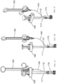
FIG. 1A is a front view of the overall assembly of an endoscopic resection assembly. -
FIG. 1B is a side view of the overall assembly shown inFIG. 1A . -
FIG. 1C is a perspective view of the overall assembly shown inFIG. 1A . -
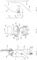
FIG. 2A is an exploded view of an endoscopic resection assembly shown inFIGS. 1A-1C . -
FIG. 2B is an enlarged view of a cutting device, a pusher, and a clip shown inFIG. 2A . -
FIG. 2C is an enlarged view of a first sheath, a second sheath, a first driver, a second driver, a snare drive cable, an adaptor, and a catheter shown inFIG. 2A . -
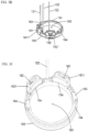
FIG. 2D is a perspective view of a pusher. -
FIG. 3A is a perspective view of the assembly of a pusher and a cutting device. -
FIG. 3B is a perspective view of the assembly of a pusher, a cutting device, a first driver, and a second driver. -
FIG. 3C is a perspective view of the assembly of a pusher and a cutting device. -
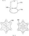
FIG. 3D is a perspective view of a cutting device, a catheter, and an adaptor. -
FIG. 3E is an illustration of a clip. -
FIG. 4 is an illustration of an adaptor, a clip, and the assembly of a pusher, a cutting device, a first driver, a second driver, and a catheter. -
FIG. 5A is a perspective view of the assembly of a pusher and a clip with an adaptor. -
FIG. 5B is a perspective view of the assembly of a pusher and a clip with an adaptor during a resection operation. -
FIG. 5C is a perspective view of the assembly of a pusher and a clip with an adaptor during a resection operation. -
FIG. 6A is a perspective view of the overall assembly of an endoscopic resection assembly in a deployed position. -
FIG. 6B is a front view of the overall assembly of an endoscopic resection assembly in a deployed position. -
FIG. 6C is an enlarged view of an adaptor, a pusher, a clip, a cutting device, a catheter, a first sheath, a second sheath, a first driver, and a second driver in a deployed position shown inFIG. 6A . -
FIG. 6D is an enlarged view of an adaptor, a pusher, a clip, a cutting device, a catheter, a first sheath, a second sheath, a first driver, and a second driver in a deployed position according toFIG. 6B . - The invention now will be described more fully hereinafter. As used in the specification, and in the appended claims, the singular forms "a", "an", and "the", include plural referents unless the context clearly dictates otherwise.
- The present invention can be used for cutting into or through the muscularis of the GI tract in order to remove dysplasia that has invaded past the mucosal layer of tissue. A clip can be deployed over the tissue prior to resection in order to pre-close the resulting defect created from the resection.
- As illustrated in
FIGS. 1A-1C and2A-2C , as per the invention, an endoscopic resection assembly 100 includes anadaptor 170, apusher 180, acutting device 150, and aclip 160. Theadaptor 170 is configured to attach to an endoscopic device. As illustrated inFIGS. 5A-5C , thepusher 180 is disposed on theadaptor 170 and configured to slide in the axial direction with respect to theadaptor 170. Thecutting device 150 is an endoscopic tool for cutting a tissue, which operates between an open state and a closed state. As illustrated inFIGS. 3A and3B , thecutting device 150 is removably coupled to thepusher 180. Theclip 160 is an endoscopic tool configured to operate between an open state and a closed state, and is configured to engage onto a tissue. As illustrated inFIGS. 5A-5C , theclip 160 is loaded on theadaptor 170 in the open state at a position distal to thepusher 180. The endoscopic resection assembly 100 further includes at least one driver, controlled by an operator, configured to slide thepusher 180 in the distal direction with respect to theadaptor 170. As thepusher 180 slides in the distal direction with respect to theadaptor 170, theclip 160 is pushed by thepusher 180 to slide off thedistal edge 1701 of theadaptor 170, and engages onto a tissue by reforming toward the closed state. Thecutting device 150 can then be activated by the operator to detach from thepusher 180, and resect tissue above the pusher by operating toward the closed state. - As illustrated in
FIG. 1A-1C and2A-2C , the endoscopic resection assembly 100 may include at least one driver and at least one sheath, acatheter 140, aclip deployment handle 190, and ahandle 130. The at least one driver may comprise afirst driver 121 and asecond driver 122. The at least one sheath may comprise afirst sheath 111 and asecond sheath 112. The drivers may be directly adjacent to one another or spaced apart somewhat along the circumference of thepusher 180. For example, the drivers may be spaced about 10 degrees to 180 degrees, or about 15 degrees to 90 degrees, or about 30 degrees, apart from one another. -
FIG. 3B illustrates the assembly of the distal components of the endoscopic resection assembly 100, including thepusher 180, thecutting device 150, and the at least one driver. Thecutting device 150 is an endoscopic tool for cutting a tissue, and operates between an open state and a closed state. Thecutting device 150 has asnare drive cable 152 and asnare loop 154. Thepusher 180 includes at least one retainer. As illustrated inFIG. 3B , the at least one retainer comprises thefirst retainer 183 and thesecond retainer 184, and retains thesnare loop 154, such that thecutting device 150 is removably coupled to thepusher 180. Thepusher 180 is driven by the at least one driver. As illustrated inFIG. 3B , the at least one driver comprises thefirst driver 121 and thesecond driver 122. Thefirst driver 121 and thesecond driver 122 can be actuated to move thepusher 180 in the distal direction. - As illustrated in
FIGS. 5A-5C , thepusher 180 is disposed on theadaptor 170 and configured to slide in the axial direction with respect to theadaptor 170. Theadaptor 170 may comprise a material to reduce friction and support movement of thepusher 180 and theclip 160. Suitable materials for theadaptor 170 include plastics such as polycarbonate, K-resin, acrylic, xylar, ASA, polypropylene, silicone, and TPES, or other similar materials. Theadaptor 170 may comprise such plastics, or other materials, entirely or in part. Theclip 160 is an endoscopic tool configured to operate between an open state and a closed state, and is configured to engage onto a tissue. Theclip 160 is loaded on the adaptor in the open state at a position distal to thepusher 180. Thepusher 180 and theclip 160 may not be secured together. However, thepusher 180 and theclip 160 may be secured together. For example, one or more indents can be formed on thepusher 180, and one or more protrusions can be formed on theclip 160, where the one or more protrusions are configured to be secured into the one or more indents. Thepusher 180 and theclip 160 can be secured together by other means such as welding, gluing, and overmolding. Thesnare drive cable 152 of thecutting device 150 extends within thecatheter 140. Thecatheter 140 may be coupled with theadaptor 170. The at least one driver may respectively extend within the at least one sheath. As illustrated inFIG. 2C , thefirst driver 121 and thesecond driver 122 respectively extend within thefirst sheath 111 and thesecond sheath 112. The at least one sheath can be attached to theadaptor 170. - The at least one driver can be actuated to move the
pusher 180 in the distal direction. As a result, thepusher 180 slides in the distal direction with respect to theadaptor 170. As thepusher 180 slides in the distal direction with respect to theadaptor 170, theclip 160 is pushed by the pusher to slide off thedistal edge 1701 of theadaptor 170, and engage onto a tissue by reverting to the closed state. Thecutting device 150 can be activated to detach from thepusher 180, and cut a tissue by operating toward the closed state. - As illustrated in
FIGS. 2A and 2C , theadaptor 170 has an inside surface and an outside surface. Theadaptor 170 may include alumen 173 and at least one overmolding. As illustrated inFIGS. 2A and 2C , the at least one overmolding may comprise anovermolding 171 and anovermolding 172. - The
adaptor 170 may be substantially tubular with a distal open end and a proximal open end. Theadaptor 170 may be hollow and define a tissue chamber channel. Theadaptor 170 may be configured to attach with different types of endoscopic devices (e.g., Olympus®, Fujinon®, or Pentax® endoscopes). For example, the inner and outer surface of theadaptor 170 may be contoured, and the inner and outer diameter of theadaptor 170 may be varied, in order to provide a good fit with the endoscopic device. The endoscopic device may be press-fitted to the proximal end of theadaptor 170. Flexible materials, such as rubber and other elastic polymers, can be overmolded or glued on the inside surface of theadaptor 170 in order to strengthen the fitting of the endoscopic device and theadaptor 170. Theadaptor 170 may comprise a flexible band, such as a rubber band, configured to be wrapped around the distal end of the endoscopic device. A person skilled in the art should understand that the shape of theadaptor 170 or the shape the tissue chamber channel can be any suitable shapes as long as it does not interfere with the operations of the endoscopic device. The tissue chamber channel may be configured to receive the tissue to be resected during resection operation. Theadaptor 170 may be entirely or partially formed with materials sufficiently transparent to allow visualization of outside environment through various optical features from the inside of theadaptor 170. During resection operation, the sufficiently transparent materials may allow the operator to confirm whether theclip 160 is deployed, and observe the position of thecutting device 150 prior to tissue resection. - The
adaptor 170 is configured to allow theclip 160 and thepusher 180 to be disposed on theadaptor 170. As illustrated inFIGS. 5A-5C , theadaptor 170 is configured to allow theclip 160 and thepusher 180 to be disposed on the outside surface of theadaptor 170. Theadaptor 170 is configured to allow theclip 160 and thepusher 180 to slide in the axial direction with respect to theadaptor 170. As illustrated inFIGS. 5A-5C , the outside surface of theadaptor 170 may be a smooth surface such that theclip 160 and thepusher 180 can slide in the axial direction with respect to theadaptor 170. - A person skilled in the art should understand that the
adaptor 170 may have any shape and may include any structural components, as long as theclip 160 and thepusher 180 can be disposed on theadaptor 170 and slide in the axial direction with respect to theadaptor 170. For example, theadaptor 170 is configured to allow theclip 160 and/or thepusher 180 to be disposed on the inside surface of theadaptor 170. Theadaptor 170 may include a support surface formed inside theadaptor 170, such that theclip 160 and/or thepusher 180 can be disposed on the support surface. Theadaptor 170 can include one or more guide rails, such that theclip 160 and/or thepusher 180 are allowed to slide in the axial direction along the one or more guide rails. Theadaptor 170 can include one or more longitudinal slits, such that theclip 160 and/or thepusher 180 are allowed to slide in the axial direction along the one or more longitudinal slits. - The
adaptor 170 may be configured to couple with thecatheter 140. As illustrated inFIG. 2C , , theadaptor 170 is coupled with thecatheter 140 by inserting thecatheter 140 into thelumen 173 of theadaptor 170. Thelumen 173 may be formed on the outside surface of theadaptor 170, such that thecatheter 140 is coupled with the outside surface of theadaptor 170. Thelumen 173 may provide slip fit between thecatheter 140 and theadaptor 170, such that thecatheter 140 is allowed to freely slide in the axial direction with respect to theadaptor 170. A person skilled in the art should understand that thecatheter 140 may be coupled to any portion of theadaptor 170, such as the inside surface of theadaptor 170, as long as thecatheter 140 does not interfere with the operations of the endoscopic device and other components of the endoscopic resection assembly 100. Thecatheter 140 may penetrate theadaptor 170, such that thecatheter 140 extends through a hole formed on theadaptor 170. In addition, a person skilled in the art should understand that theadaptor 170 can be fixed with thecatheter 140, or be detached from thecatheter 140, as long as thecatheter 140 does not interfere with the operations of the endoscopic device and other components of the endoscopic resection assembly 100. - The
adaptor 170 may be configured to attach with the at least one sheath. As illustrated inFIGS. 5A-5C , the at least one sheath may comprise thefirst sheath 111 and thesecond sheath 112, and thefirst sheath 111 and thesecond sheath 112 may be attached to theadaptor 170 respectively by theovermolding 171 and theovermolding 172. Theovermolding 171 and theovermolding 172 may be formed on the outside surface of theadaptor 170, such that the at least one sheath is attached to the outside surface of theadaptor 170. A person skilled in the art should understand that the at least one sheath can be attached with theadaptor 170 by other means, for example, friction, heat staking, gluing, or welding. A person skilled in the art should also understand that the at least one sheath can be attached to any portion of theadaptor 170, such as the inside surface of theadaptor 170, as long as the at least one sheath does not interfere with the operations of the endoscopic device and other components of the endoscopic resection assembly 100. The at least one sheath may penetrate theadaptor 170, such that the at least one sheath extends through a hole formed on theadaptor 170. In addition, a person skilled in the art should understand that the at least one sheath may not be attached with theadaptor 170. Instead, the at least one sheath may be attached with any component of the endoscopic device or the endoscopic resection assembly 100, as long as the at least one sheath does not interfere with the operations of the endoscopic device and other components of the endoscopic resection assembly 100. - As illustrated in
FIG. 2B , thepusher 180 includes at least one knob which comprises thefirst knob 181 and thesecond knob 182, and at least one retainer which comprises thefirst retainer 183 and thesecond retainer 184. - The
pusher 180 may be configured to be disposed on theadaptor 170 and can slide in the axial direction with respect to theadaptor 170. As illustrated inFIG. 2B , thepusher 180 is substantially ring-shaped, defining acentral opening 185. As illustrated inFIG. 5A , the adaptor can be inserted into thecentral opening 185, such that thepusher 180 is disposed on the outside surface of theadaptor 170 and can slide in the axial direction with respect to theadaptor 170. Thecentral opening 185 may have different shapes to fit with the different shapes of the outside surface of theadaptor 170. Thepusher 180 may be configured to be disposed on the inside surface or the outside surface of theadaptor 170, or on a support surface formed inside theadaptor 170. Thepusher 180 may include structural components, such as protrusions and indents, to fit with guide rails, longitudinal slits, or other structural components of theadaptor 170, such that thepusher 180 can slide in the axial direction with respect to theadaptor 170. - The
pusher 180 may have a closed ring structure configured to be disposed on the entire periphery of theadaptor 170, as illustrated inFIG. 5A . A person skilled in the art should understand that thepusher 180 may be disposed on a portion of the periphery of theadaptor 170, as long as there is no interference with the operations of the endoscopic device and other components of the endoscopic resection assembly 100. For example, thepusher 180 may have a half-ring structure configured to be disposed on a half of the periphery of theadaptor 170. - The
pusher 180 may be attached with at least one driver. Thepusher 180 may include at least one knob for attaching with the at least one driver. As illustrated inFIGS. 2B and 2C , the at least one driver comprises afirst driver 121 and asecond driver 122, and the at least one knob comprises thefirst knob 181 and thesecond knob 182. As illustrated inFIGS. 2C and3B , the distal ends of thefirst driver 121 and thesecond driver 122 are bent into a circle and fitted around thefirst knob 181 and thesecond knob 182. As such, the at least one driver is secured to the at least one knob of thepusher 180. The at least one knob is a round knob over which the bent distal end of the at least one driver can be snapped into place. A person skilled in the art should understand that the at least one driver may fit with, or be secured to, other structural components of thepusher 180, for example, one or more holes formed on thepusher 180. Glue may be applied to reinforce the attachment of the at least one driver to thepusher 180. The at least one driver may be attached to thepusher 180 by different means, for example, gluing, welding, or overmolding. - The at least one driver is configured to move the
pusher 180 in the distal direction. As illustrated inFIGS. 5A-5C , thefirst driver 121 and thesecond driver 122 respectively extend within thefirst sheath 111 and thesecond sheath 112. Thefirst driver 121 and thesecond driver 122 can be actuated to advance in the distal direction with respect to thefirst sheath 111 and thesecond sheath 112, pushing thepusher 180 in the distal direction. A person skilled in the art should understand that the at least one driver may comprise various structural components configured to move thepusher 180 in the distal direction. For example, the at least one driver can comprise a pull thread with a distal end tied on thepusher 180, where the pull thread is configured to pull thepusher 180 in the distal direction when a proximal end of the pull thread is retracted. A person skilled in the art should also understand that the at least one driver may not be coupled or attached to thepusher 180, as long as thepusher 180 can be driven by the at least one driver in the distal direction. - A spring may be coupled to the clip deployment handle 190 or the at least one sheath. The spring can be configured to be compressed or extended, such that the spring exerts a force on the at least one driver in the axial direction. The clip deployment handle 190 can include a stopper for preventing the axial movement of the at least one driver with respect to the at least one sheath. The clip deployment handle 190 can be configured to activate the stopper by, for example, deforming the stopper, such that the stopper no longer prevents the axial movement of the at least one driver. As result, the compressed or extended spring moves the at least one driver in the axial direction with respect to the at least one sheath, and the at least one driver moves the
pusher 180 in the distal direction. - The
pusher 180 may be spring loaded on theadaptor 170. A spring can be coupled with theadaptor 170 and configured to be compressed or extended by thepusher 180 when thepusher 180 is disposed on theadaptor 170. As such, the spring exerts a force on thepusher 180 in the distal direction. A stopper can be coupled to theadaptor 170, the endoscopic device, or other structural components of the endoscopic resection assembly 100, and can be configured to prevent the distal movement of thepusher 180 with respect to theadaptor 170. An actuator, such as a pull thread extending within a sheath, can be operatively coupled with the stopper. The actuator may be configured to activate the stopper by, for example, deforming the stopper or detaching the stopper from other structural components, such that the stopper no longer prevents the distal movement of thepusher 180. As result, the compressed spring pushes thepusher 180, and thepusher 180 slides in the distal direction with respect to theadaptor 170. - The
adaptor 170 may be slidably coupled with the endoscopic device, such that theadaptor 170 can slide in the axial direction with respect to the endoscopic device. An actuator, such as a pull thread extending within a sheath, can be operatively coupled with the adaptor. The actuator may be configured to move theadaptor 170 in the proximal direction with respect to the endoscopic device and thepusher 180, such that thepusher 180 moves in the distal direction in relative to theadaptor 170. - The
pusher 180 may be removably coupled with thecutting device 150. Thecutting device 150 is an endoscopic tool for cutting a tissue, which operates between an open state and a closed state. As illustrated inFIG. 2B , thecutting device 150 includes asnare drive cable 152 and asnare loop 154.FIG. 2B illustrates thecutting device 150 in the open state. Thesnare drive cable 152 can be actuated to contract thesnare loop 154, such that thecutting device 150 operates toward the closed state. - The
pusher 180 includes at least one retainer. As illustrated inFIGS. 2D and 3A , the at least one retainer may comprise afirst retainer 183 and asecond retainer 184. Each of the at least one retainer may define a passage and a slit. As illustrated inFIGS. 2D and 3A , thefirst retainer 183 defines apassage 1831 and aslit 1832, and thesecond retainer 184 defines apassage 1841 and aslit 1842. The passage defined by the at least one retainer may be configured to accommodate thesnare loop 154 of thecutting device 150. The slit defined by the at least one retainer may be configured to communicate the passage with thecentral opening 185 defined by thepusher 180.FIG. 3B illustrates the assembly of thecutting device 150 with thepusher 180. As illustrated inFIG. 3B , thesnare loop 154 is in the open state and accommodated in thepassage 1831 defined by thefirst retainer 183 and thepassage 1841 defined by thesecond retainer 184. As such, thesnare loop 154 lies in a plane substantially parallel to the plane defined by thepusher 180, and moves in tandem with thepusher 180 when thepusher 180 moves in the axial direction. When thesnare loop 154 is contracted by actuating thesnare drive cable 152, theslit 1832 defined by thefirst retainer 183 and theslit 1842 defined by thesecond retainer 184 allow thesnare loop 154 to escape from the passage and move radially inward into thecentral opening 185 defined by thepusher 180. Thepusher 180 can be formed from one or more components that could be snapped, glued, or welded together to form the at least one retainer that removably retains thecutting device 150 to thepusher 180. - The
pusher 180 may include at least one housing formed around the at least one knob. As illustrated inFIG. 3C , ahousing 1811 can be formed around theknob 181 and ahousing 1821 can be formed around theknob 182. As illustrated inFIG. 3C , thesnare loop 154 is bent at the positions where the at least one housing is located, such that thesnare loop 154 is positioned along the inward facing surface of the at least one housing. As such, the at least one housing does not block the operation of thesnare loop 154 between the open state and the closed state. A person skilled in the art should understand that thesnare loop 154 can be bent or deformed to extend around various structural components formed on thepusher 180, such that the structural components do not block the operation of thesnare loop 154 between the open state and the closed state. A person skilled in the art should also understand that passages for accommodating thesnare loop 154 can be formed on the surface of the various structural components of thepusher 180, such that the structural components do not block the operation of thesnare loop 154 between the open state and the closed state. - As illustrated in
FIGS. 2D and 3A , the at least one retainer is formed on the proximal surface of thepusher 180. As such, when thesnare loop 154 is accommodated in the passage formed through the at least one retainer, thesnare loop 154 is positioned at a set distance from the distal surface of thepusher 180. The set distance can be, for example, 2 to 4 mm or 1 to 5 mm. The set distance can be varied depending on user need and anatomical constraints. A person skilled in the art should understand that the at least one retainer may comprise various structural components configured to removably couple with thecutting device 150. IThe at least one retainer may comprise a groove configured to hold thesnare loop 154. The at least one retainer may comprise holes or indents configured to fit with bent or protruding portions of thesnare loop 154. A person skilled in the art should also understand that the at least one retainer may be formed on any portion of thepusher 180, for example, the proximal surface, the distal surface, the inward facing surface, or the outward facing surface. - The
pusher 180 can be removably coupled with thesnare loop 154 by various means. Thesnare loop 154 can be detachably glued to thepusher 180. Thesnare loop 154 can be magnetically attached to thepusher 180. Thesnare loop 154 can be removably coupled to thepusher 180 by a breakable seal. The breakable seal may comprise a rigid seal attached to thepusher 180 and configured to detach from thepusher 180. The breakable seal may also comprise a soft seal attached to thepusher 180, where thesnare loop 154 is configured to break the seal by cutting through the soft seal. A person skilled in the art should understand that when thesnare loop 154 is removably coupled with thepusher 180, thesnare loop 154 can be positioned at a set distance from the distal surface of thepusher 180, where the set distance can be, for example, 2 to 4 mm or 1 to 5 mm. - The
cutting device 150 is an endoscopic tool for resecting tissue, and operates between an open state and a closed state. As illustrated inFIG. 2B , thecutting device 150 includes thesnare drive cable 152 and thesnare loop 154. Thesnare drive cable 152 and thesnare loop 154 may be formed with conductive metal wire, which allows the use of diathermic energy by directing electric current in thesnare drive cable 152 and thesnare loop 154. Thesnare drive cable 152 and thesnare loop 154 can be formed with materials including stainless steel, nitinol, nickel-titanium shape memory alloy, and polymers such as PTFE, polyolefin, and fluorinated ethylene propylene. Thesnare drive cable 152 can be attached to thesnare loop 154 by welding at an angle substantially perpendicular to the plane defined by thesnare loop 154. As illustrated inFIG. 3D , thesnare drive cable 152 extends within thecatheter 140. The proximal end of thesnare drive cable 152 is operatively coupled with thehandle 130.FIGS. 2B and3D illustrate thecutting device 150 in the open state. Thehandle 130 may be configured to retract thesnare drive cable 152 with respect to thecatheter 140. As result, thesnare drive cable 152 pulls a portion or the entirety of thesnare loop 154 into thecatheter 140, such that thesnare loop 154 is contracted toward the closed state having a smaller loop area than the loop area of the open state. - The
cutting device 150 may be one integral piece of wire. Thecutting device 150 may extend within thecatheter 140 from the proximal end to the distal end, protrudes out of the distal end of thecatheter 140 to form a snare loop, and extends within thecatheter 140 back from the distal end to the proximal end. As such, both ends of thecutting device 150 are positioned at the proximal end of thecatheter 140, where thecatheter 140 is operatively coupled with thehandle 130. Thehandle 130 may be configured to actuate thecutting device 150 by retracting one end or both ends of thecutting device 150 with respect to thecatheter 140, such that thesnare loop 154 is contracted. - The
cutting device 150 may be one integral piece of wire. Thecutting device 150 may extend within thecatheter 140, with the proximal end positioned at the proximal end of thecatheter 140 and the distal end attached to the distal end of thecatheter 140. Thehandle 130 may be configured to actuate thecutting device 150 by retracting the proximal end of thecutting device 150 with respect to thecatheter 140, such that thesnare loop 154 is contracted. - The
cutting device 150 may be removably coupled with the pusher 180As illustrated inFIG. 3B , thesnare loop 154 of thecutting device 150 may be retained in thepassage 1831 and thepassage 1841 defined by the at least one retainer of thepusher 180. When thesnare drive cable 152 is retracted by thehandle 130, thesnare loop 154 is contracted to escape from thepassage 1831 and thepassage 1841 through theslit 1832 and theslit 1842 defined by thepusher 180, and move radially inward into thecentral opening 185 defined by thepusher 180. - A person skilled in the art should understand that the
cutting device 150 may comprise any known endoscopic tools for cutting a tissue, as long as thecutting device 150 can be removably coupled with thepusher 180. Thecutting device 150 may comprise one or more jaws for cutting a tissue. A person skilled in the art should also understand that thecutting device 150 may be removably coupled to any portion of thepusher 180, for example, the proximal surface, the distal surface, the inward facing surface, or the outward facing surface of thepusher 180. In addition, a person skilled in the art should understand that thecutting device 150 can be positioned at a set distance from the distal surface of thepusher 180, where the set distance can be, for example, 2 to 4 mm or 1 to 5 mm. - As illustrated in
FIG. 3B , thecutting device 150 may be removably coupled to thepusher 180 in the open state. A person skilled in the art should understand that thecutting device 150 may comprise various endoscopic tools allowing the operation between an open state and a closed state. Thecutting device 150 may be removably coupled to thepusher 180 in the closed state or an intermediate state between the open state and the closed state. - The
clip 160 may be an endoscopic clip which can be deployed to engage onto a tissue. The clip may be based on the Padlock Clip® Defect Closure System currently marketed by STERIS Corporation. Theclip 160 may comprise a plurality of tines for engaging the tissue. Each tine of theclip 160 may be blunt or pointed for various purposes, for example, stopping bleeding by compressing the tissue, allowing for optimal healing abilities while still allowing blood flow to the tissue, and holding the tissue together until the site heals itself.FIG. 2B illustrates theclip 160 in the open state, andFIG. 3E illustrates theclip 160 in the closed state. Theclip 160 is made from resilient materials which can store strain energy, for example, elastic metal alloy such as nitinol. Theclip 160 can be formed with materials including stainless steel, nitinol, nickel-titanium shape memory alloy, and polymers such as PTFE, polyolefin, and fluorinated ethylene propylene. Theclip 160 rests in the closed state when no external force is applied, and can be deformed into the open state by application of external force. When in the open state, theclip 160 defines acentral opening 165. When the external force is no longer applied, theclip 160 releases the stored energy and reforms back to the closed state. -
FIG. 4 illustrates the assembly of thepusher 180 and theclip 160 onto theadaptor 170. Thepusher 180 is disposed on theadaptor 170 by inserting theadaptor 170 into thecentral opening 185 defined by thepusher 180. In other words, thepusher 180 rides along the outside surface of theadaptor 170, where thepusher 180 can slide in the axial direction with respect to theadaptor 170. The at least one driver is attached to thepusher 180 by securing onto the at least one knob of thepusher 180. Theclip 160 is deformed into the open state by external force, and theclip 160 in the open state defines acentral opening 165. Theclip 160 is then loaded onto theadaptor 170 at a position distal to thepusher 180. The outside surface of theadaptor 170 supports theclip 160 such that theclip 160 is maintained in the open state, which creates a friction against the sliding of theclip 160 with respect to theadaptor 170 in the axial direction. When a predetermined amount of force is exerted on theclip 160 in the distal direction, theclip 160 overcomes the friction to slide off thedistal edge 1701 of theadaptor 170 and detach from theadaptor 170.FIG. 5A illustrates thepusher 180 and theclip 160 assembled onto theadaptor 170. As illustrated inFIG. 5A , theclip 160 contacts thepusher 180 such that theclip 160 can be pushed in the distal direction when thepusher 180 moves in the distal direction. - A person skilled in the art should understand that the
clip 160 can be loaded onto the inside surface or the outside surface of theadaptor 170, or onto a support surface formed inside theadaptor 170, as long as theclip 160 can be maintained in the open position and can slide off thedistal edge 1701 of theadaptor 170. Theclip 160 and thepusher 180 can be disposed on different surfaces of theadaptor 170, where theadaptor 170 provides one or more longitudinal slits allowing thepusher 180 to contact theclip 160 and push theclip 160 in the distal direction. - The
pusher 180 may not contact and push theclip 160 in the distal direction. Instead, a clip driver such as a drive wire or a pull thread can be configured to move theclip 160 in the distal direction, such that theclip 160 can slide off thedistal edge 1701 of theadaptor 170. - Each of the at least one sheath defines a passage for each of the at least one driver. As illustrated in
FIG. 2C , thefirst driver 121 and thesecond driver 122 respectively extends within thefirst sheath 111 and thesecond sheath 112. The at least one sheath can be reinforced sheaths, such as a spring sheath, formed with various materials including, but not limited to stainless steel, HDPE, PTFE, and nitinol. The at least one sheath may be coated inside or outside to improve the deployment of the device. A heat shrink may be applied over the top of the at least one sheath to increase strength along lengths where the sheath transitions from flexible to stiffer segments of the assembly. - The proximal end of the at least one sheath can be coupled with the
clip deployment handle 190. The distal end of the at least one sheath is attached to theadaptor 170 by, for example, heat staking, gluing, welding, or overmolding. As illustrated inFIG. 5A , thefirst sheath 111 and thesecond sheath 112 are attached to theadaptor 170 respectively by theovermolding 171 and theovermolding 172. As illustrated inFIG. 2C , theovermolding 171 and theovermolding 172 may be integrally formed with thelumen 173 by one step of overmolding. Each of the at least one sheath can be separately attached to theadaptor 170, either before or after thelumen 173 is formed. A person skilled in the art should understand that the at least one sheath can be attached to any portion of theadaptor 170, such as the inside surface of theadaptor 170, as long as the at least one sheath does not interfere with the operations of the endoscopic device and other components of the endoscopic resection assembly 100. The at least one sheath may penetrate theadaptor 170, such that the at least one sheath extends through a hole formed on theadaptor 170. In addition, a person skilled in the art should understand that the at least one sheath may not be attached with theadaptor 170. Instead, the at least one sheath may be attached with any component of the endoscopic device or the endoscopic resection assembly 100, as long as the at least one sheath does not interfere with the operations of the endoscopic device and other components of the endoscopic resection assembly 100. - The at least one driver comprises endoscopic tools for pushing the
pusher 180 in the distal direction. As illustrated inFIG. 2C , the at least one driver comprises thefirst driver 121 and thesecond driver 122 which are drive wires respectively extending within thefirst sheath 111 and thesecond sheath 112. The proximal end of the at least one driver may operatively couple with theclip deployment handle 190. The clip deployment handle 190 is configured to actuate the at least one driver, such that the at least one driver advances with respect to the at least one sheath. - The
catheter 140 is a catheter configured for allowing the operation of thecutting device 150 between the open state and the closed state. Thecatheter 140 may define a passage for thesnare drive cable 152 of thecutting device 150. Thecatheter 140 can be a sheath formed with various materials including, but not limited to stainless steel, HDPE, PTFE, and nitinol. Thecatheter 140 and the at least one sheath, for example thefirst sheath 111 and thesecond sheath 112, may be contained within the same catheter subassembly, such as in a multilumen catheter sheath. The proximal end of thecatheter 140 may be coupled with thehandle 130. As illustrated inFIG. 2C , thecatheter 140 is coupled with theadaptor 170 by slip fitting into thelumen 173 of theadaptor 170. A person skilled in the art should understand that thecatheter 140 may be coupled to any portion of theadaptor 170, such as the inside surface of theadaptor 170, as long as thecatheter 140 does not interfere with the operations of the endoscopic device and other components of the endoscopic resection assembly 100. Thecatheter 140 may penetrate theadaptor 170, such that thecatheter 140 extends through a hole formed on theadaptor 170. In addition, a person skilled in the art should understand that thecatheter 140 can be fixed with theadaptor 170, or be detached from theadaptor 170, as long as thecatheter 140 does not interfere with the operations of the endoscopic device and other components of the endoscopic resection assembly 100. - Additionally, a marking device, such as a probe, can be provided in the endoscopic device to outline the perimeter of the target tissue to be resected.
- In operation (not according to the invention), the endoscopic resection assembly is mounted on an endoscopic device through the
adaptor 170 configured to attach with the endoscopic device (e.g., Olympus®, Fujinon®, or Pentax® endoscopes) by, for example, press fitting. The operator guides the endoscope into the GI tract and to the lesion that needs to be resected. The perimeter of the target tissue to be resected can be marked with a marking device, such as a probe, provided in the endoscopic device. - In a next step (not according to the invention), the target tissue to be resected is recruited into the tissue chamber channel defined by the
adaptor 170. In cases where the target tissue is a lesion, some extra tissue surrounding the lesion in addition to the lesion can be recruited into theadaptor 170, which ensures that the entire lesion can be resected and removed. An endoscopic grasper may be provided in theadaptor 170. The endoscopic grasper may advance out of theadaptor 170, grasp a tissue, and pull the tissue into theadaptor 170. Tissue can be recruited into theadaptor 170 via suction or by other means and endoscopic tools. When the perimeter of the target tissue is initially marked with a marking device, the marked edges can help the operator in determining whether the target tissue is entirely pulled into the cap. - In a next step (not according to the invention), the
clip 160 is deployed over the tissue. The clip deployment handle 190 may be actuated to advance the at least one driver with respect to the at least one sheath. Through the attachment of thepusher 180 with the at least one driver, a force may be exerted on thepusher 180 in the distal direction. As result, as illustrated inFIGS. 5A-5C , thepusher 180 moves in the distal direction with respect to theadaptor 170. Theclip 160 may be loaded on theadaptor 170 at a position distal to thepusher 180 and maintained in the open state. As thepusher 180 moves in the distal direction, the distal surface of thepusher 180 may contact theclip 160 to exert a force sufficient to overcome the friction between theclip 160 and theadaptor 170. As result, theclip 160 slides against the outside surface of theadaptor 170 in the distal direction. As theclip 160 slides off thedistal edge 1701 of theadaptor 170, as illustrated inFIGS. 5B and 5C , the support provided by the outside surface of theadaptor 170 becomes insufficient to maintain theclip 160 in the open state. Due to the energy stored in theclip 160, theclip 160 reforms toward the closed state where the tines of theclip 160 engage onto the tissue recruited into theadaptor 170. In cases where the target tissue is a lesion, theclip 160 may engage onto some extra or marginal tissue surrounding the lesion which ensures that the entire lesion can be resected and removed. - The clip deployment handle 190 may be further actuated to advance the at least one driver, which further moves the
pusher 180 in the distal direction. The clip deployment handle 190 is actuated until thepusher 180 sits directly on top of theclip 160.FIGS. 6A-6D illustrates theclip 160 and thepusher 180 in the deployed position where the tissue is not shown. As illustrated inFIGS. 6A-6D , when thepusher 180 is in the deployed position, at least a portion of thepusher 180 is distal to theadapter 170. In other words, at least a portion of thepusher 180 in the deployed position extends beyond theedge 1701 of theadaptor 170. For example, thepusher 180 in the deployed position may extend beyond theedge 1701 of theadaptor 170 by 0 to 3 cm. - In a next step (not according to the invention), the tissue is resected by operating the
cutting device 150. Thecutting device 150 is operated from the open state toward the closed state while cutting the tissue. Thecutting device 150 is operated from the closed state toward the open state, and then operated from the open state toward the closed state while cutting the tissue. Thehandle 130 is actuated to retract thesnare drive cable 152 with respect to thecatheter 140, which pulls thesnare loop 154 into thecatheter 140. As result, thesnare loop 154 is contracted such that thecutting device 150 operates from the open state toward the closed state. Thecutting device 150 is removably coupled to thepusher 180 where thesnare loop 154 is accommodated in the passage defined by the at least one retainer of thepusher 180. When contracted, thesnare loop 154 escapes from the passage through the slit defined by the at least one retainer, and moves radially inward into thecentral opening 185 defined by thepusher 180. As such, thecutting device 150 is removed from thepusher 180, and the tissue recruited in theadaptor 170 is resected by thesnare loop 154 moving radially inward. Diathermic energy may be applied through the snare loop to assist the resection. The amount of tissue that can be resected is affected by the axial distance between the distal end of thepusher 180 and the position on thepusher 180 where thecutting device 150 is coupled. As illustrated in FIGS. 2D and 3A-3C, thecutting device 150 is coupled to the top surface of thepusher 180. As such, the axial distance between the distal end of thepusher 180 and the position on thepusher 180 where thecutting device 150 is coupled is equivalent to the stack height of thepusher 180, that is, the distance between the top surface and the bottom surface of thepusher 180. When thepusher 180 has a large stack height, there is a large axial distance between the distal end of thepusher 180 and the position on thepusher 180 where thecutting device 150 is coupled. Therefore, the resection will be shallow, with less tissue being resected by thecutting device 150 and more tissue remaining within thecentral opening 185 defined by thepusher 180 after resection. In contrast, when thepusher 180 has a small stack height, there is a small axial distance between the distal end of thepusher 180 and the position on thepusher 180 where thecutting device 150 is coupled. Therefore, the resection will be deep, with more tissue being resected by thecutting device 150 and less tissue remaining within thecentral opening 185 defined by thepusher 180 after resection. The axial distance between the distal end of thepusher 180 and the position on thepusher 180 where thecutting device 150 is coupled can be varied and adjusted, for example by adjusting the stack height of thepusher 180, in order to ensure there is an appropriate amount of tissue to be resected as well as an appropriate amount of tissue remaining within thecentral opening 185 defined by thepusher 180 after resection. After resection, some tissue remains at the resection site on the proximal side of theclip 160 due to the axial distance between theclip 160 and the position on thepusher 180 where thecutting device 150 is coupled, which ensures that theclip 160 remains engaged with the tissue to close the defect. When thesnare loop 154 is accommodated in the passages positioned at 1 to 5 mm from the distal surface of thepusher 180, about 1 to 5 mm of tissue will remain on the proximal side of theclip 160 after resection. The endoscopic resection assembly, except for theclip 160, is then removed from the GI tract. For a less traumatic removal process, the clip deployment handle 190 can be actuated to retract the at least one driver which moves thepusher 180 in the proximal direction and back onto theadaptor 170. - A spring may be coupled to the clip deployment handle 190 or the at least one sheath. The spring can be configured to be compressed or extended when the
pusher 180 is in the deployed position, such that the spring exerts a force on the at least one driver in the proximal direction. The clip deployment handle 190 can include a stopper for preventing retraction of the at least one driver with respect to the at least one sheath. The clip deployment handle 190 can be configured to activate the stopper by, for example, deforming the stopper, such that the stopper no longer prevents the proximal movement of the at least one driver. As result, the compressed or extended spring moves the at least one driver in the proximal direction with respect to the at least one sheath, and the at least one driver moves thepusher 180 in the proximal direction and back onto theadaptor 170.
Claims (12)
- An endoscopic resection assembly (100), comprising:(a) an adaptor (170), configured to couple to an endoscopic device;(b) a pusher (180), disposed on the adaptor (170);(c) at least one driver, configured to move the pusher (180) in a distal direction with respect to the adaptor (170); and(d) a cutting device (150), removably coupled to the pusher (180),wherein the cutting device (150) is configured to be removed from the pusher (180) when at least a portion of the pusher is distal to the adaptor (170),wherein the adaptor (170) is configured to be loaded with a clip (160), wherein the clip (160) is configured to operate between an open state and a closed state wherein the clip (160) is configured to be loaded on the adaptor (170) in the open state at a position distal to the pusher (180), wherein the clip (160) is configured to be pushed by the pusher (180) to slide off the distal edge (1701) of the adaptor (170) so that the clip (160) is configured to be released from the adaptor (170) and to engage onto a tissue before the cutting device (150) is removed from the pusher (180).
- The endoscopic resection assembly of claim 1, wherein the cutting device (150) comprises a snare drive cable (152) and a snare loop (154), and wherein the snare loop (154) is configured to contract when the snare drive cable (152) is activated
- The endoscopic resection assembly of claim 2, wherein the pusher (180) comprises at least one retainer, and wherein the snare loop (154) is accommodated in a passage defined by at least one retainer
- The endoscopic resection assembly of claim 3, wherein the at least one retainer defines a slit, and wherein the snare loop (154) is configured to escape from the passage through the slit when the snare loop (154) is contracted.
- The endoscopic resection assembly of claim 1, wherein the cutting device (150) is positioned at a set distance from a distal surface of the pusher
- The endoscopic resection assembly of claim 5, wherein the set distance is 1 to 5 mm.
- The endoscopic resection assembly of claim 1, wherein the pusher (180) is disposed on the outside surface of the adaptor (170), and the clip (160) is configured to be loaded on the outside surface of the adaptor (170).
- The endoscopic resection assembly of claim 1, wherein the pusher (180) is configured to push the clip (160) in a distal direction, so that the clip (160) is configured to be released from the adaptor (170) and to engage onto a tissue.
- The endoscopic resection assembly of claim 1, wherein the pusher (180) and the clip (160) are secured together.
- The endoscopic resection assembly of claim 1, wherein an endoscopic grasper is configured to recruit the tissue into the adaptor (170) before the clip (160) engages onto the tissue.
- The endoscopic resection assembly of claim 1, wherein the at least one driver is configured to move the pusher (180) to a position directly on top of the clip (160) after the clip (160) engages onto the tissue
- The endoscopic resection assembly of claim 1, wherein the at least one driver is configured to move the pusher (180) so that the pusher (180) extends beyond an edge of the adaptor (170) by 0 to 3 cm after the clip (160) engages onto the tissue.
Applications Claiming Priority (2)
| Application Number | Priority Date | Filing Date | Title |
|---|---|---|---|
| US202063089360P | 2020-10-08 | 2020-10-08 | |
| PCT/US2021/054266 WO2022076882A1 (en) | 2020-10-08 | 2021-10-08 | Endoscopic resection assembly |
Publications (2)
| Publication Number | Publication Date |
|---|---|
| EP4225155A1 EP4225155A1 (en) | 2023-08-16 |
| EP4225155B1 true EP4225155B1 (en) | 2025-01-29 |
Family
ID=78529017
Family Applications (1)
| Application Number | Title | Priority Date | Filing Date |
|---|---|---|---|
| EP21802871.0A Active EP4225155B1 (en) | 2020-10-08 | 2021-10-08 | Endoscopic resection assembly |
Country Status (4)
| Country | Link |
|---|---|
| US (1) | US11771455B2 (en) |
| EP (1) | EP4225155B1 (en) |
| JP (1) | JP7646822B2 (en) |
| WO (1) | WO2022076882A1 (en) |
Families Citing this family (5)
| Publication number | Priority date | Publication date | Assignee | Title |
|---|---|---|---|---|
| KR20240125064A (en) | 2022-06-10 | 2024-08-19 | 보스턴 사이언티픽 메디칼 디바이스 리미티드 | Repositionable over-the-scope clip with interchangeable mechanism |
| EP4295784A1 (en) * | 2022-06-22 | 2023-12-27 | B. Braun Surgical, S.A. | Surgical assembly, process for manufacturing a surgical assembly and device for manufacturing a surgical assembly |
| US12471928B2 (en) * | 2022-07-06 | 2025-11-18 | Boston Scientific Medical Device Limited | Repositionable over-the-scope clip with cancer seeding prevention in full tissue resection |
| CN120358989A (en) * | 2022-10-17 | 2025-07-22 | 波士顿科学医疗设备有限公司 | Medical systems, devices, and related methods |
| WO2024242952A1 (en) * | 2023-05-19 | 2024-11-28 | United States Endoscopy Group, Inc. | Endoscopic full thickness resection (eftr) device |
Family Cites Families (5)
| Publication number | Priority date | Publication date | Assignee | Title |
|---|---|---|---|---|
| US5968056A (en) * | 1997-11-13 | 1999-10-19 | Boston Scientific Corporation | Device and method for severing lesions |
| US8062308B2 (en) * | 2007-10-23 | 2011-11-22 | Minos Medical | Devices and methods for securing tissue |
| EP2358255B1 (en) | 2008-11-18 | 2019-01-09 | United States Endoscopy Group, Inc. | Adapter for attaching devices to endoscopes |
| US9155554B2 (en) * | 2011-10-27 | 2015-10-13 | Boston Scientific Scimed, Inc. | Tissue resection bander and related methods of use |
| US20140100423A1 (en) * | 2012-07-18 | 2014-04-10 | Leonid Monassevitch | Endoscopic full thickness resection using surgical compression clips |
-
2021
- 2021-10-08 EP EP21802871.0A patent/EP4225155B1/en active Active
- 2021-10-08 JP JP2023521559A patent/JP7646822B2/en active Active
- 2021-10-08 WO PCT/US2021/054266 patent/WO2022076882A1/en not_active Ceased
- 2021-10-08 US US17/497,677 patent/US11771455B2/en active Active
Also Published As
| Publication number | Publication date |
|---|---|
| US11771455B2 (en) | 2023-10-03 |
| US20220110652A1 (en) | 2022-04-14 |
| WO2022076882A1 (en) | 2022-04-14 |
| EP4225155A1 (en) | 2023-08-16 |
| JP7646822B2 (en) | 2025-03-17 |
| JP2023544843A (en) | 2023-10-25 |
Similar Documents
| Publication | Publication Date | Title |
|---|---|---|
| US11771455B2 (en) | Endoscopic resection assembly | |
| EP2330986B1 (en) | Endoscopic suturing device | |
| JP4266743B2 (en) | Endoscopic hood and endoscopic mucosal resection tool | |
| JP4643328B2 (en) | Medical ligature suturing device | |
| US5947983A (en) | Tissue cutting and stitching device and method | |
| US20070066869A1 (en) | Endoscopic assembly including cap and sheath | |
| EP3456238B1 (en) | Method of attaching devices to endoscopes using an adapter | |
| CN114554974B (en) | Filament cutting device | |
| US9872600B2 (en) | Tissue resection bander and related methods of use | |
| US20080015613A1 (en) | System and method for endoscopic treatment of tissue | |
| KR20060117278A (en) | Medical device for use with endoscope | |
| US20240122595A1 (en) | Systems, devices, and related methods for fastening tissue | |
| CN113766885A (en) | Systems, devices, and related methods for securing tissue | |
| JP2020523177A (en) | Tissue clip application mounting set/retrofitting set | |
| JP2018535738A (en) | Endoscopic cap with deflection channel for endoscopic treatment | |
| JP2020508825A (en) | Jaw assembly and biopsy sample collection member for surgical tools | |
| JP2022530239A (en) | Traction system for endoscopic procedures and how to use it | |
| JPH10286224A (en) | Endoscope for ligating | |
| US20240366214A1 (en) | Devices, systems, and methods for articulation and/or retroflexion of a medical device | |
| CN114585312A (en) | Systems, devices and related methods for securing tissue | |
| EP4287961B1 (en) | Over the scope clip with compliant mechanism | |
| JP4542562B2 (en) | Medical ligature | |
| US20240366215A1 (en) | Devices, systems, and methods for performing a procedure with respect to tissue | |
| CA3157972A1 (en) | Biopsy forceps with tissue piercing member | |
| JP2026515980A (en) | Devices, systems, and methods for performing procedures on an organization |
Legal Events
| Date | Code | Title | Description |
|---|---|---|---|
| STAA | Information on the status of an ep patent application or granted ep patent |
Free format text: STATUS: UNKNOWN |
|
| STAA | Information on the status of an ep patent application or granted ep patent |
Free format text: STATUS: THE INTERNATIONAL PUBLICATION HAS BEEN MADE |
|
| PUAI | Public reference made under article 153(3) epc to a published international application that has entered the european phase |
Free format text: ORIGINAL CODE: 0009012 |
|
| STAA | Information on the status of an ep patent application or granted ep patent |
Free format text: STATUS: REQUEST FOR EXAMINATION WAS MADE |
|
| 17P | Request for examination filed |
Effective date: 20230331 |
|
| AK | Designated contracting states |
Kind code of ref document: A1 Designated state(s): AL AT BE BG CH CY CZ DE DK EE ES FI FR GB GR HR HU IE IS IT LI LT LU LV MC MK MT NL NO PL PT RO RS SE SI SK SM TR |
|
| DAV | Request for validation of the european patent (deleted) | ||
| DAX | Request for extension of the european patent (deleted) | ||
| P01 | Opt-out of the competence of the unified patent court (upc) registered |
Effective date: 20240116 |
|
| STAA | Information on the status of an ep patent application or granted ep patent |
Free format text: STATUS: EXAMINATION IS IN PROGRESS |
|
| 17Q | First examination report despatched |
Effective date: 20240405 |
|
| GRAP | Despatch of communication of intention to grant a patent |
Free format text: ORIGINAL CODE: EPIDOSNIGR1 |
|
| STAA | Information on the status of an ep patent application or granted ep patent |
Free format text: STATUS: GRANT OF PATENT IS INTENDED |
|
| RIC1 | Information provided on ipc code assigned before grant |
Ipc: A61B 17/30 20060101ALN20240919BHEP Ipc: A61B 17/128 20060101ALI20240919BHEP Ipc: A61B 1/00 20060101ALI20240919BHEP Ipc: A61B 17/3205 20060101ALI20240919BHEP Ipc: A61B 17/122 20060101ALI20240919BHEP Ipc: A61B 17/00 20060101AFI20240919BHEP |
|
| INTG | Intention to grant announced |
Effective date: 20241011 |
|
| GRAS | Grant fee paid |
Free format text: ORIGINAL CODE: EPIDOSNIGR3 |
|
| GRAA | (expected) grant |
Free format text: ORIGINAL CODE: 0009210 |
|
| STAA | Information on the status of an ep patent application or granted ep patent |
Free format text: STATUS: THE PATENT HAS BEEN GRANTED |
|
| AK | Designated contracting states |
Kind code of ref document: B1 Designated state(s): AL AT BE BG CH CY CZ DE DK EE ES FI FR GB GR HR HU IE IS IT LI LT LU LV MC MK MT NL NO PL PT RO RS SE SI SK SM TR |
|
| REG | Reference to a national code |
Ref country code: GB Ref legal event code: FG4D |
|
| REG | Reference to a national code |
Ref country code: CH Ref legal event code: EP |
|
| REG | Reference to a national code |
Ref country code: DE Ref legal event code: R096 Ref document number: 602021025533 Country of ref document: DE |
|
| REG | Reference to a national code |
Ref country code: IE Ref legal event code: FG4D |
|
| REG | Reference to a national code |
Ref country code: NL Ref legal event code: MP Effective date: 20250129 |
|
| PG25 | Lapsed in a contracting state [announced via postgrant information from national office to epo] |
Ref country code: NL Free format text: LAPSE BECAUSE OF FAILURE TO SUBMIT A TRANSLATION OF THE DESCRIPTION OR TO PAY THE FEE WITHIN THE PRESCRIBED TIME-LIMIT Effective date: 20250129 |
|
| PG25 | Lapsed in a contracting state [announced via postgrant information from national office to epo] |
Ref country code: RS Free format text: LAPSE BECAUSE OF FAILURE TO SUBMIT A TRANSLATION OF THE DESCRIPTION OR TO PAY THE FEE WITHIN THE PRESCRIBED TIME-LIMIT Effective date: 20250429 |
|
| PG25 | Lapsed in a contracting state [announced via postgrant information from national office to epo] |
Ref country code: FI Free format text: LAPSE BECAUSE OF FAILURE TO SUBMIT A TRANSLATION OF THE DESCRIPTION OR TO PAY THE FEE WITHIN THE PRESCRIBED TIME-LIMIT Effective date: 20250129 |
|
| PG25 | Lapsed in a contracting state [announced via postgrant information from national office to epo] |
Ref country code: PL Free format text: LAPSE BECAUSE OF FAILURE TO SUBMIT A TRANSLATION OF THE DESCRIPTION OR TO PAY THE FEE WITHIN THE PRESCRIBED TIME-LIMIT Effective date: 20250129 |
|
| PG25 | Lapsed in a contracting state [announced via postgrant information from national office to epo] |
Ref country code: ES Free format text: LAPSE BECAUSE OF FAILURE TO SUBMIT A TRANSLATION OF THE DESCRIPTION OR TO PAY THE FEE WITHIN THE PRESCRIBED TIME-LIMIT Effective date: 20250129 |
|
| REG | Reference to a national code |
Ref country code: LT Ref legal event code: MG9D |
|
| PG25 | Lapsed in a contracting state [announced via postgrant information from national office to epo] |
Ref country code: NO Free format text: LAPSE BECAUSE OF FAILURE TO SUBMIT A TRANSLATION OF THE DESCRIPTION OR TO PAY THE FEE WITHIN THE PRESCRIBED TIME-LIMIT Effective date: 20250429 Ref country code: IS Free format text: LAPSE BECAUSE OF FAILURE TO SUBMIT A TRANSLATION OF THE DESCRIPTION OR TO PAY THE FEE WITHIN THE PRESCRIBED TIME-LIMIT Effective date: 20250529 |
|
| REG | Reference to a national code |
Ref country code: AT Ref legal event code: MK05 Ref document number: 1762663 Country of ref document: AT Kind code of ref document: T Effective date: 20250129 |
|
| PG25 | Lapsed in a contracting state [announced via postgrant information from national office to epo] |
Ref country code: HR Free format text: LAPSE BECAUSE OF FAILURE TO SUBMIT A TRANSLATION OF THE DESCRIPTION OR TO PAY THE FEE WITHIN THE PRESCRIBED TIME-LIMIT Effective date: 20250129 |
|
| PG25 | Lapsed in a contracting state [announced via postgrant information from national office to epo] |
Ref country code: LV Free format text: LAPSE BECAUSE OF FAILURE TO SUBMIT A TRANSLATION OF THE DESCRIPTION OR TO PAY THE FEE WITHIN THE PRESCRIBED TIME-LIMIT Effective date: 20250129 Ref country code: PT Free format text: LAPSE BECAUSE OF FAILURE TO SUBMIT A TRANSLATION OF THE DESCRIPTION OR TO PAY THE FEE WITHIN THE PRESCRIBED TIME-LIMIT Effective date: 20250529 |
|
| PG25 | Lapsed in a contracting state [announced via postgrant information from national office to epo] |
Ref country code: GR Free format text: LAPSE BECAUSE OF FAILURE TO SUBMIT A TRANSLATION OF THE DESCRIPTION OR TO PAY THE FEE WITHIN THE PRESCRIBED TIME-LIMIT Effective date: 20250430 Ref country code: BG Free format text: LAPSE BECAUSE OF FAILURE TO SUBMIT A TRANSLATION OF THE DESCRIPTION OR TO PAY THE FEE WITHIN THE PRESCRIBED TIME-LIMIT Effective date: 20250129 |
|
| PG25 | Lapsed in a contracting state [announced via postgrant information from national office to epo] |
Ref country code: AT Free format text: LAPSE BECAUSE OF FAILURE TO SUBMIT A TRANSLATION OF THE DESCRIPTION OR TO PAY THE FEE WITHIN THE PRESCRIBED TIME-LIMIT Effective date: 20250129 |
|
| PG25 | Lapsed in a contracting state [announced via postgrant information from national office to epo] |
Ref country code: SE Free format text: LAPSE BECAUSE OF FAILURE TO SUBMIT A TRANSLATION OF THE DESCRIPTION OR TO PAY THE FEE WITHIN THE PRESCRIBED TIME-LIMIT Effective date: 20250129 |
|
| PG25 | Lapsed in a contracting state [announced via postgrant information from national office to epo] |
Ref country code: SM Free format text: LAPSE BECAUSE OF FAILURE TO SUBMIT A TRANSLATION OF THE DESCRIPTION OR TO PAY THE FEE WITHIN THE PRESCRIBED TIME-LIMIT Effective date: 20250129 |
|
| PG25 | Lapsed in a contracting state [announced via postgrant information from national office to epo] |
Ref country code: DK Free format text: LAPSE BECAUSE OF FAILURE TO SUBMIT A TRANSLATION OF THE DESCRIPTION OR TO PAY THE FEE WITHIN THE PRESCRIBED TIME-LIMIT Effective date: 20250129 |
|
| PG25 | Lapsed in a contracting state [announced via postgrant information from national office to epo] |
Ref country code: EE Free format text: LAPSE BECAUSE OF FAILURE TO SUBMIT A TRANSLATION OF THE DESCRIPTION OR TO PAY THE FEE WITHIN THE PRESCRIBED TIME-LIMIT Effective date: 20250129 Ref country code: CZ Free format text: LAPSE BECAUSE OF FAILURE TO SUBMIT A TRANSLATION OF THE DESCRIPTION OR TO PAY THE FEE WITHIN THE PRESCRIBED TIME-LIMIT Effective date: 20250129 |
|
| PG25 | Lapsed in a contracting state [announced via postgrant information from national office to epo] |
Ref country code: RO Free format text: LAPSE BECAUSE OF FAILURE TO SUBMIT A TRANSLATION OF THE DESCRIPTION OR TO PAY THE FEE WITHIN THE PRESCRIBED TIME-LIMIT Effective date: 20250129 |
|
| PG25 | Lapsed in a contracting state [announced via postgrant information from national office to epo] |
Ref country code: SK Free format text: LAPSE BECAUSE OF FAILURE TO SUBMIT A TRANSLATION OF THE DESCRIPTION OR TO PAY THE FEE WITHIN THE PRESCRIBED TIME-LIMIT Effective date: 20250129 |
|
| REG | Reference to a national code |
Ref country code: DE Ref legal event code: R097 Ref document number: 602021025533 Country of ref document: DE |
|
| PLBE | No opposition filed within time limit |
Free format text: ORIGINAL CODE: 0009261 |
|
| STAA | Information on the status of an ep patent application or granted ep patent |
Free format text: STATUS: NO OPPOSITION FILED WITHIN TIME LIMIT |
|
| 26N | No opposition filed |
Effective date: 20251030 |
|
| PGFP | Annual fee paid to national office [announced via postgrant information from national office to epo] |
Ref country code: DE Payment date: 20251029 Year of fee payment: 5 |
|
| PGFP | Annual fee paid to national office [announced via postgrant information from national office to epo] |
Ref country code: GB Payment date: 20251027 Year of fee payment: 5 |
|
| PGFP | Annual fee paid to national office [announced via postgrant information from national office to epo] |
Ref country code: IT Payment date: 20251021 Year of fee payment: 5 |
|
| PGFP | Annual fee paid to national office [announced via postgrant information from national office to epo] |
Ref country code: FR Payment date: 20251027 Year of fee payment: 5 |