EP4224827A1 - Vibration motor and terminal device - Google Patents
Vibration motor and terminal device Download PDFInfo
- Publication number
- EP4224827A1 EP4224827A1 EP22879667.8A EP22879667A EP4224827A1 EP 4224827 A1 EP4224827 A1 EP 4224827A1 EP 22879667 A EP22879667 A EP 22879667A EP 4224827 A1 EP4224827 A1 EP 4224827A1
- Authority
- EP
- European Patent Office
- Prior art keywords
- vibration motor
- terminal device
- middle frame
- housing
- screen
- Prior art date
- Legal status (The legal status is an assumption and is not a legal conclusion. Google has not performed a legal analysis and makes no representation as to the accuracy of the status listed.)
- Granted
Links
Images







Classifications
-
- H—ELECTRICITY
- H02—GENERATION; CONVERSION OR DISTRIBUTION OF ELECTRIC POWER
- H02K—DYNAMO-ELECTRIC MACHINES
- H02K33/00—Motors with reciprocating, oscillating or vibrating magnet, armature or coil system
- H02K33/02—Motors with reciprocating, oscillating or vibrating magnet, armature or coil system with armatures moved one way by energisation of a single coil system and returned by mechanical force, e.g. by springs
-
- H—ELECTRICITY
- H04—ELECTRIC COMMUNICATION TECHNIQUE
- H04M—TELEPHONIC COMMUNICATION
- H04M1/00—Substation equipment, e.g. for use by subscribers
- H04M1/02—Constructional features of telephone sets
- H04M1/0202—Portable telephone sets, e.g. cordless phones, mobile phones or bar type handsets
- H04M1/026—Details of the structure or mounting of specific components
-
- H—ELECTRICITY
- H02—GENERATION; CONVERSION OR DISTRIBUTION OF ELECTRIC POWER
- H02K—DYNAMO-ELECTRIC MACHINES
- H02K33/00—Motors with reciprocating, oscillating or vibrating magnet, armature or coil system
- H02K33/16—Motors with reciprocating, oscillating or vibrating magnet, armature or coil system with polarised armatures moving in alternate directions by reversal or energisation of a single coil system
-
- H—ELECTRICITY
- H02—GENERATION; CONVERSION OR DISTRIBUTION OF ELECTRIC POWER
- H02K—DYNAMO-ELECTRIC MACHINES
- H02K5/00—Casings; Enclosures; Supports
- H02K5/04—Casings or enclosures characterised by the shape, form or construction thereof
-
- H—ELECTRICITY
- H02—GENERATION; CONVERSION OR DISTRIBUTION OF ELECTRIC POWER
- H02K—DYNAMO-ELECTRIC MACHINES
- H02K5/00—Casings; Enclosures; Supports
- H02K5/04—Casings or enclosures characterised by the shape, form or construction thereof
- H02K5/10—Casings or enclosures characterised by the shape, form or construction thereof with arrangements for protection from ingress, e.g. water or fingers
-
- H—ELECTRICITY
- H02—GENERATION; CONVERSION OR DISTRIBUTION OF ELECTRIC POWER
- H02K—DYNAMO-ELECTRIC MACHINES
- H02K5/00—Casings; Enclosures; Supports
- H02K5/04—Casings or enclosures characterised by the shape, form or construction thereof
- H02K5/22—Auxiliary parts of casings not covered by groups H02K5/06-H02K5/20, e.g. shaped to form connection boxes or terminal boxes
- H02K5/225—Terminal boxes or connection arrangements
-
- H—ELECTRICITY
- H04—ELECTRIC COMMUNICATION TECHNIQUE
- H04M—TELEPHONIC COMMUNICATION
- H04M1/00—Substation equipment, e.g. for use by subscribers
- H04M1/02—Constructional features of telephone sets
- H04M1/0202—Portable telephone sets, e.g. cordless phones, mobile phones or bar type handsets
- H04M1/0206—Portable telephones comprising a plurality of mechanically joined movable body parts, e.g. hinged housings
- H04M1/0208—Portable telephones comprising a plurality of mechanically joined movable body parts, e.g. hinged housings characterized by the relative motions of the body parts
- H04M1/0214—Foldable telephones, i.e. with body parts pivoting to an open position around an axis parallel to the plane they define in closed position
- H04M1/0216—Foldable in one direction, i.e. using a one degree of freedom hinge
-
- H—ELECTRICITY
- H04—ELECTRIC COMMUNICATION TECHNIQUE
- H04M—TELEPHONIC COMMUNICATION
- H04M1/00—Substation equipment, e.g. for use by subscribers
- H04M1/02—Constructional features of telephone sets
- H04M1/0202—Portable telephone sets, e.g. cordless phones, mobile phones or bar type handsets
- H04M1/026—Details of the structure or mounting of specific components
- H04M1/0266—Details of the structure or mounting of specific components for a display module assembly
-
- H—ELECTRICITY
- H04—ELECTRIC COMMUNICATION TECHNIQUE
- H04M—TELEPHONIC COMMUNICATION
- H04M1/00—Substation equipment, e.g. for use by subscribers
- H04M1/02—Constructional features of telephone sets
- H04M1/0202—Portable telephone sets, e.g. cordless phones, mobile phones or bar type handsets
- H04M1/026—Details of the structure or mounting of specific components
- H04M1/0266—Details of the structure or mounting of specific components for a display module assembly
- H04M1/0268—Details of the structure or mounting of specific components for a display module assembly including a flexible display panel
-
- H—ELECTRICITY
- H04—ELECTRIC COMMUNICATION TECHNIQUE
- H04M—TELEPHONIC COMMUNICATION
- H04M1/00—Substation equipment, e.g. for use by subscribers
- H04M1/02—Constructional features of telephone sets
- H04M1/0202—Portable telephone sets, e.g. cordless phones, mobile phones or bar type handsets
- H04M1/026—Details of the structure or mounting of specific components
- H04M1/0277—Details of the structure or mounting of specific components for a printed circuit board assembly
-
- H—ELECTRICITY
- H04—ELECTRIC COMMUNICATION TECHNIQUE
- H04M—TELEPHONIC COMMUNICATION
- H04M1/00—Substation equipment, e.g. for use by subscribers
- H04M1/02—Constructional features of telephone sets
- H04M1/18—Telephone sets specially adapted for use in ships, mines, or other places exposed to adverse environment
-
- H—ELECTRICITY
- H04—ELECTRIC COMMUNICATION TECHNIQUE
- H04M—TELEPHONIC COMMUNICATION
- H04M1/00—Substation equipment, e.g. for use by subscribers
- H04M1/02—Constructional features of telephone sets
- H04M1/0202—Portable telephone sets, e.g. cordless phones, mobile phones or bar type handsets
- H04M1/0206—Portable telephones comprising a plurality of mechanically joined movable body parts, e.g. hinged housings
- H04M1/0208—Portable telephones comprising a plurality of mechanically joined movable body parts, e.g. hinged housings characterized by the relative motions of the body parts
- H04M1/0214—Foldable telephones, i.e. with body parts pivoting to an open position around an axis parallel to the plane they define in closed position
-
- H—ELECTRICITY
- H04—ELECTRIC COMMUNICATION TECHNIQUE
- H04M—TELEPHONIC COMMUNICATION
- H04M2250/00—Details of telephonic subscriber devices
- H04M2250/16—Details of telephonic subscriber devices including more than one display unit
Definitions
- This application relates to the field of terminal device technologies, and in particular, to a vibration motor and a terminal device with a vibration motor.
- a vibration motor In a terminal device such as a mobile phone, a tablet, or a wearable device, vibration is usually generated by using a vibration motor, to implement functions such as an incoming call or SMS message reminder and a vibration tactile feedback.
- a vibration motor With the advance in science and technology, terminal devices gradually become thin. Especially, for a foldable phone, a thickness of the entire phone urgently needs to be reduced. Consequently, mounting space of a vibration motor in the terminal device is gradually reduced.
- thinning of the vibration motor causes vibration performance reduction. Therefore, a current thickness of the vibration motor becomes one of bottlenecks that impede further thinning of the terminal device. It can be learned that how to reduce a thickness of a terminal device (especially a foldable phone) without sacrificing performance of a vibration motor becomes a current design difficulty.
- Embodiments of this application provide a vibration motor and a terminal device, to reduce a thickness of a terminal device without sacrificing performance of a vibration motor.
- a terminal device includes a first screen, a first middle frame, and a vibration motor. At least a part of the first screen is located on one side of the first middle frame and is stacked with the first middle frame.
- the vibration motor is located on a side that is of the first middle frame and that is away from the at least part of the first screen.
- the vibration motor includes a housing, one end of the housing is opened to form an opening, the opening faces the first middle frame, and an edge of the housing at the opening is fastened to the first middle frame.
- the opening on the housing of the vibration motor is blocked by using the first middle frame, to form a closed housing, thereby achieving a waterproof and dustproof protection function to some extent.
- the first middle frame forms a wall plate of the housing of the vibration motor. Without changing a height of internal accommodation space of the vibration motor, a height of the vibration motor can be reduced, to reduce a mounting height of the vibration motor in the terminal device. This helps reduce a thickness of the terminal device. Because the height of the internal accommodation space of the vibration motor is unchanged, a design height of a structure such as a mass block in the housing does not need to be limited, so that performance of the vibration motor can be ensured.
- the housing includes a top wall and a side frame, the side frame is disposed around a circumference of the top wall, and an end that is of the side frame and that is away from the top wall surrounds the opening.
- the structure of the housing is simple, and the top wall and the side frame may be formed integrally by using a stamping process. In some other embodiments, the top wall and the side frame may be formed separately and assembled together. This can facilitate assembly of an internal structure.
- the vibration motor further includes a mass block.
- the mass block is disposed in the housing, and the mass block can reciprocally vibrate relative to the housing on a plane parallel to a plane on which the opening is located.
- a vibration path of the mass block may be a straight line, or may be a curve.
- a vibration direction of the mass block is perpendicular to a thickness direction of the terminal device. This helps reduce a thickness of the vibration motor, and helps reduce a mounting height of the vibration motor in the terminal device.
- an elastic assembly is configured to elastically support the mass block in the housing, and the elastic assembly allows the mass block to vibrate reciprocally in the housing. In this way, vibration stability of the mass block can be ensured.
- the elastic assembly includes a first elastic member and a second elastic member. Both the first elastic member and the second elastic member are springs. An arrangement direction of the first elastic member, the mass block, and the second elastic member is parallel to the vibration direction of the mass block.
- the first elastic member includes a first fastening part, a first connection part, and a second fastening part that are connected in sequence.
- the first fastening part is connected to the mass block, and a connection manner includes but is not limited to welding, sticking, or integral molding.
- the second fastening part is connected to the side frame of the housing, and a connection manner includes but is not limited to welding, sticking, or integral molding.
- the first connection part is approximately of an n shape, an arch direction of the first connection part is parallel to the plane on which the opening is located, and the arch direction of the first connection part is perpendicular to the vibration direction of the mass block.
- the second elastic member includes a third fastening part, a second connection part, and a fourth fastening part that are connected in sequence.
- the third fastening part is connected to the mass block, and a connection manner includes but is not limited to welding or sticking.
- the fourth fastening part is connected to the side frame of the housing, and a connection manner includes but is not limited to welding or sticking.
- the second connection part is approximately of an n shape, and an arch direction of the second connection part is opposite to the arch direction of the first connection part. In this way, both the first elastic member and the second elastic member have a capability of deforming in a direction parallel to the vibration direction of the mass block. This structure is simple and easy to implement.
- the vibration motor further includes a drive assembly.
- the drive assembly includes a magnet assembly and a coil.
- the magnet assembly is fastened to the mass block, the coil is located between the mass block and the top wall, the coil is fastened to the top wall of the housing, the magnet assembly cooperates with the coil to generate a Lorentz force, and the Lorentz force is used to drive the mass block to reciprocally vibrate relative to the housing on the plane parallel to the plane on which the opening is located.
- a structure of the drive assembly is simple, and the magnet assembly may alternatively participate in vibration as a part of the mass block.
- the coil is fastened to the top wall of the housing, a layout is proper, and a support structure of the coil does not need to be additionally disposed. This helps reduce a height of the vibration motor.
- the vibration motor further includes an electrical connection structure.
- the electrical connection structure includes a first segment, a second segment, and a third segment that are sequentially connected.
- the first segment is fastened to an inner surface of the top wall
- the coil is fastened to the first segment and electrically connected to the first segment
- the second segment is fastened to an inner surface of the side frame
- the third segment extends in a radial direction of the opening
- a part of the third segment is located outside the housing
- a positive terminal and a negative terminal are disposed on the part that is of the third segment and that is located outside the housing.
- the electrical connection structure can lead an electrode of the coil to the third segment outside the housing, and when the vibration motor is used in the terminal device, the third segment of the electrical connection structure can be fastened and supported by using the first middle frame. That is, when the vibration motor is used in the terminal device, the third segment of the electrical connection structure is attached to and fastened to the first middle frame. Therefore, the third segment is fastened and supported by using the first middle frame.
- the electrical connection structure is a flexible circuit board.
- a connection lug is disposed on an outer surface of the side frame, and the edge of the housing at the opening is fastened to the first middle frame by using the connection lug. Stability and reliability of this connection manner are relatively high, and neither of a limiting structure and a buffer material layer needs to be disposed on a side that is of the housing and that is away from the first middle frame, so that a mounting height of the vibration motor on the first middle frame can be reduced to some extent.
- a region occupied by the connection lug is relatively small, and space is reserved on a side that is of the lug and that is away from the first middle frame, so that other parts around the vibration motor can be accommodated.
- connection lug includes a fastening part, a lug part, and a connection hole
- the fastening part is fastened to the outer surface of the side frame
- the lug part is fastened to the fastening part
- the connection hole is disposed in the lug part
- an axial direction of the connection hole is consistent with an extension direction of a central axis of the opening.
- the edge of the housing at the opening is welded to the first middle frame. Stability of welding is relatively high, so that connection stability of the vibration motor on the first middle frame can be improved.
- neither of a limiting structure and a buffer material layer needs to be disposed on a side that is of the housing and that is away from the first middle frame, so that a mounting height of the vibration motor on the first middle frame can be reduced to some extent.
- the first screen includes a first part and a second part, and the first part of the first screen is located on one side of the first middle frame and is stacked with the first middle frame.
- the terminal device further includes a second middle frame, where the second middle frame is rotatably connected to the first middle frame, the second part is disposed on one side of the second middle frame and is stacked with the second middle frame, the terminal device can change between an unfolded state and a folded state, and when the terminal device is in the unfolded state, the first part of the first screen and the second part of the first screen face a same side, or when the terminal device is in the folded state, the first part of the first screen and the second part of the first screen face each other or back onto each other.
- the terminal device is a foldable terminal device, and a wall plate of the housing of the vibration motor is formed by using the first middle frame. Without changing a height of internal accommodation space of the vibration motor, a height of the vibration motor can be reduced. This helps reduce a thickness of the foldable terminal device, to improve a hand feeling, a texture, and portability of the foldable terminal.
- the terminal device when the terminal device is in the folded state, the first part of the first screen and the second part of the first screen face each other.
- the terminal device further includes a second screen, where the second screen is located on a side that is of the vibration motor and that is away from the first middle frame, the second screen and the first middle frame are relatively fastened, and the vibration motor and the second screen are spaced from each other.
- the terminal device is an inward-foldable terminal having two screens, and a wall plate of the housing of the vibration motor is formed by using the first middle frame. Without changing a height of internal accommodation space of the vibration motor, a height of the vibration motor can be reduced. This helps reduce a thickness of the foldable terminal device, to improve a hand feeling, a texture, and portability of the foldable terminal.
- a gap between the vibration motor and the second screen is 0.05 millimeters to 0.35 millimeters. In some embodiments, a width of the gap is 0.1 millimeters to 0.2 millimeters. The gap width is suitable, so that a thickness of the foldable terminal can be reduced while preventing the vibration motor from impacting on the second screen.
- a height of the vibration motor is less than or equal to 3.0 millimeters. In this way, the height of the vibration motor is relatively small. This facilitates a thinning design of the terminal device.
- a plurality of vibration motors may all be disposed in first accommodation space of the terminal device or may all be disposed in second accommodation space of the terminal device, or some vibration motors may be disposed in the first accommodation space and the other vibration motors may be disposed in the second accommodation space.
- a disposing position of the vibration motors in the first accommodation space and a disposing position of the vibration motors in the second accommodation space may be symmetrical with respect to a rotation axis of a rotation mechanism.
- a vibration motor includes a housing, and one end of the housing is opened to form an opening.
- the vibration motor When the vibration motor provided in this application is used in a terminal device, the vibration motor may be disposed on a side that is of a first middle frame and that is away from a first screen, the opening of the housing of the vibration motor faces the first middle frame, and an edge of the housing at the opening is fastened to the first middle frame. In this way, the opening on the housing of the vibration motor is blocked by using the first middle frame, to form a closed housing, thereby achieving a waterproof and dustproof protection function to some extent.
- the first middle frame forms a wall plate of the housing of the vibration motor. Without changing a height of internal accommodation space of the vibration motor, a height of the vibration motor can be reduced, to reduce a mounting height of the vibration motor in the terminal device. This helps reduce a thickness of the terminal device. Because the height of the internal accommodation space of the vibration motor is unchanged, a design height of a structure such as a mass block in the housing does not need to be limited, so that performance of the vibration motor can be ensured.
- the housing includes a top wall and a side frame, the side frame is disposed around a circumference of the top wall, and an end that is of the side frame and that is away from the top wall surrounds the opening.
- the structure of the housing is simple, and the top wall and the side frame may be formed integrally by using a stamping process. In some other embodiments, the top wall and the side frame may be formed separately and assembled together. This can facilitate assembly of an internal structure.
- a connection lug is disposed on an outer surface of the side frame, the connection lug includes a fastening part, a lug part, and a connection hole, the fastening part is fastened to the outer surface of the side frame, the lug part is fastened to the fastening part, the connection hole is disposed in the lug part, and an axial direction of the connection hole is consistent with an extension direction of a central axis of the opening.
- a removable dustproof structure covers the opening. This can avoid a problem of jamming and rusting of the vibration motor caused when dust enters the vibration motor during transportation, storage, and sale of the vibration motor.
- the dustproof structure is gummed paper.
- the gummed paper has low costs and high removal efficiency, and is easy to operate.
- the gummed paper has specific waterproof performance, and can prevent moisture from entering the vibration motor.
- first and second are merely used for description, but should not be understood as indicating or implying relative importance or implying a quantity of indicated technical features. Therefore, a feature limited by “first” or “second” may explicitly or implicitly include one or more features.
- the term "include”, “have”, or any other variant thereof is intended to cover non-exclusive inclusion, so that a process, method, article, or apparatus that includes a series of elements includes not only those elements but also other elements that are not explicitly listed, or includes elements inherent to such a process, method, article, or apparatus.
- a process, method, article, or apparatus that includes the element may further include another same element.
- position relationship qualifiers such as the terms “parallel”, “perpendicular”, “consistent”, and “opposite” all indicate approximate positions that allow a specific error.
- This application provides a terminal device, and the terminal device has a display interface and can display a video or an image.
- a vibration motor is disposed in the terminal device, and can vibrate to implement functions such as an incoming call, message, SMS message, weather, or news reminder and a tactile feedback of a touch or an accidental touch.
- a middle frame in the terminal device is used to form a wall plate of a housing of the vibration motor, to reduce a mounting height of the vibration motor in the terminal device while ensuring internal accommodation space of the vibration motor, so as to reduce a thickness of the terminal device.
- the improvement solution in this application can ensure the internal accommodation space of the vibration motor, a design volume of a structure such as a mass block in the housing does not need to be limited, so that performance of the vibration motor can be ensured.
- the thickness of the terminal device refers to a size of the terminal device in a direction perpendicular to the display interface.
- the terminal device provided in this application includes but is not limited to a tablet terminal and a foldable terminal.
- the tablet terminal includes but is not limited to a tablet phone, a tablet personal computer (tablet personal computer), a tablet laptop computer (laptop computer), a tablet personal digital assistant (personal digital assistant, PDA), a tablet in-vehicle device, a tablet wearable device, or the like.
- the foldable terminal includes but is not limited to a foldable phone or a foldable computer.
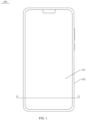
- FIG. 1 is a schematic diagram of a structure of a terminal device according to some embodiments of this application.
- FIG. 2 is a schematic diagram of a cross-sectional structure of the terminal device in FIG. 1 on a line A-A.
- the terminal device is a tablet phone 100.
- the tablet phone 100 includes a first screen 101, a first middle frame 102, a first back cover 103, and a vibration motor 104.
- the first screen 101 is located on one side of the first middle frame 102 and is stacked with the first middle frame 102.
- the first back cover 103 is located on a side that is of the first middle frame 102 and that is away from the first screen 101, and is stacked with the first middle frame 102.
- First accommodation space C1 is formed between the first back cover 103 and the first middle frame 102.
- the vibration motor 104 is located in the first accommodation space C1, and the vibration motor 104 is fastened to the first middle frame 102.
- the vibration motor 104 may be glued to the first middle frame 102, or may be fastened to the first middle frame 102 in a manner such as clamping or threaded connection.
- a thickness of the tablet phone 100 needs to be reduced.
- a mounting height h of the vibration motor 104 on the first middle frame 102 is one of bottlenecks that impede further thinning of the tablet phone 100.
- the mounting height h of the vibration motor 104 on the first middle frame 102 is a height by which an entirety including the vibration motor 104 and a connection structure protrudes from the first middle frame 102.
- the connection structure is a structure for connecting the vibration motor 104 to the first middle frame 102.
- FIG. 3 is a schematic diagram of a structure of a terminal device according to some other embodiments of this application.
- FIG. 4 is a schematic diagram of a cross-sectional structure of the terminal device in FIG. 3 on a line B-B.
- the terminal device is a foldable phone 200.
- the foldable phone 200 further includes a second middle frame 105 and a second back cover 106.
- the first middle frame 102 is rotatably connected to the second middle frame 105.
- the first middle frame 102 and the second middle frame 105 may be rotatably connected by using a rotation mechanism 108.
- the first screen 101 may be folded into a first part 101a (that is, a screen A) and a second part 101b (that is, a screen B).
- a folding axis is formed between the first part 101a and the second part 101b.
- at least a region in which the folding axis is located on the first screen 101 is made of a flexible material.
- a remaining region on the first screen 101 may be made of a flexible material, or may be made of a rigid material, or may be partially made of a rigid material and partially made of a flexible material. This is not specifically limited herein.
- the entire first screen 101 is made of a flexible material. In this way, manufacturing is convenient and costs are relatively low. However, a screen made of the flexible material is easily scratched.
- the first part 101a is located on one side of the first middle frame 102 and is stacked with the first middle frame 102.
- the second part 101b is located on one side of the second middle frame 105 and is stacked with the second middle frame 105.
- the second back cover 106 is located on a side that is of the second middle frame 105 and that is away from the second part 101b, and is stacked with the second middle frame 105.
- Second accommodation space C2 is formed between the first back cover 103 and the second middle frame 105.
- the second accommodation space C2 is configured to accommodate structures such as a battery, a main board, and a camera module.
- the foldable phone 200 can change between an unfolded state and a folded state.
- the foldable phone 200 may be classified into two types based on folding directions from the unfolded state to the folded state.
- One type is a foldable phone that is folded inward (briefly referred to as an inward-foldable phone below), and the other type is a foldable phone that is folded outward (briefly referred to as an outward-foldable phone below).
- the inward-foldable phone is in a folded state
- the first part 101a and the second part 101b face each other.
- the outward-foldable phone is in a folded state, the first part 101a and the second part 101b back onto each other.
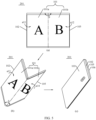
- FIG. 5 is a schematic diagram of a structure of an inward-foldable phone 201 during folding from an unfolded state to a folded state according to some embodiments of this application.
- (a) in FIG. 5 is a schematic diagram of a structure of the inward-foldable phone in the unfolded state.
- the first part 101a that is, the screen A
- the second part 101b that is, the screen B
- an included angle ⁇ between the first part 101a and the second part 101b is 180° or approximately 180°, so that large-screen display can be implemented, to provide more abundant information for a user and bring better use experience to the user.
- the included angle ⁇ between the first part 101a and the second part 101b is an included angle between the first part 101a and the second part 101b on a display side of the first screen 101.
- the display side of the first screen 101 is a side on which the first screen 101 displays an image or a video.
- the user can view an image or a video displayed on the first screen 101.
- a schematic diagram of a structure of the inward-foldable phone 201 in a half-folded state shown in (b) in FIG. 5 may be formed by folding two sides of the inward-foldable phone 201 in a direction a11 and a direction a12. In this state, the included angle ⁇ between the first part 101a and the second part 101b is greater than 0° and less than 180°. Based on this, further, a schematic diagram of a structure of the inward-foldable phone 201 in the folded state shown in (c) in FIG. 5 may be formed by continuing to fold two sides of the inward-foldable phone 201 in a direction a13 and a direction a14.
- the foldable phone 201 is completely folded, and the first part 101a and the second part 101b face each other, that is, the included angle ⁇ between the first part 101a and the second part 101b is 0° or approximately 0°.
- the first screen 101 is invisible to the user. This can prevent the first screen 101 from being scratched by a hard object.
- FIG. 6 is a schematic diagram of a structure of an outward-foldable phone 202 during folding from an unfolded state to a folded state according to some embodiments of this application.
- (a) in FIG. 6 is a schematic diagram of a structure of the outward-foldable phone 202 in the unfolded state.
- the first part 101a that is, the screen A
- the second part 101b that is, the screen B
- an included angle ⁇ between the first part 101a and the second part 101b is 180° or approximately 180°, so that large-screen display can be implemented, to provide more abundant information for a user and bring better use experience to the user.
- a schematic diagram of a structure of the outward-foldable phone in a half-folded state shown in (b) in FIG. 6 may be formed by folding two sides of the outward-foldable phone 202 in a direction a21 and a direction a22. In this state, the included angle ⁇ between the first part 101a and the second part 101b is greater than 180° and less than 360°. Based on this, further, a schematic diagram of a structure of the outward-foldable phone 202 in the folded state shown in (c) in FIG. 6 may be formed by continuing to fold two sides of the outward-foldable phone 202 in a direction a23 and a direction a24.
- the foldable phone 202 is completely folded, and the first part 101a and the second part 101b back onto each other, that is, the included angle ⁇ between the first part 101a and the second part 101b is 360° or approximately 360°.
- a volume of the foldable phone is relatively small, and the foldable phone is easy to carry.
- small-screen display may be implemented by using one of the first part 101a and the second part 101b.
- the first screen 101 is exposed to an external environment, the first screen 101 is prone to be scratched.
- FIG. 3 to FIG. 6 all show foldable phones that are folded horizontally.
- the foldable phone in embodiments of this application may alternatively be a foldable phone that is folded vertically. This is not specifically limited herein.
- the foldable phone may not be the inward-foldable phone or the outward-foldable phone, but a foldable phone that supports both inward folding and outward folding.
- a thickness of the foldable phone (including the inward-foldable phone 201, the outward-foldable phone 202, and the foldable phone that supports both inward folding and outward folding) in the folded state is a sum of thicknesses of two folding parts
- the thickness of the foldable phone in the folded state is approximately twice the thickness of the tablet phone 100 shown in FIG. 1 and FIG. 2 . Therefore, the foldable phone 200 urgently needs to be thinned to improve a hand feeling, a texture, and portability. Therefore, compared with the tablet phone 100, the foldable phone 200 more needs to be thinned by reducing the mounting height of the vibration motor 104 on the first middle frame 102.
- FIG. 7 is a schematic diagram of a cross-sectional structure of a foldable phone 203 according to some other embodiments of this application.
- the foldable phone 203 further includes a second screen 107.
- the second screen 107 is located on a side that is of the first middle frame 102 and that is away from the first screen 101, and is stacked with the first middle frame 102.
- First accommodation space C1 is formed between the second screen 107 and the first middle frame 102.
- the vibration motor 104 is located in the first accommodation space C1, and the vibration motor 104 is fastened to the first middle frame 102.
- FIG. 8 is a schematic diagram of a structure of the foldable phone 203 in FIG. 7 during folding from an unfolded state to a folded state.
- (a) in FIG. 8 is a schematic diagram of a structure of the foldable phone 203 in the unfolded state.
- the first part 101a that is, the screen A
- the second part 101b that is, the screen B
- an included angle ⁇ between the first part 101a and the second part 101b is 180° or approximately 180°, so that large-screen display can be implemented, to provide more abundant information for a user and bring better use experience to the user.
- a schematic diagram of a structure of the foldable phone 203 in a half-folded state shown in (b) in FIG. 8 may be formed by folding two sides of the foldable phone 203 in a direction a31 and a direction a32. In this state, the included angle ⁇ between the first part 101a and the second part 101b is greater than 0° and less than 180°. Based on this, further, a schematic diagram of a structure of the foldable phone 203 in the folded state shown in (c) in FIG. 8 may be formed by continuing to fold two sides of the foldable phone 203 in a direction a33 and a direction a34.
- the foldable phone 203 is completely folded, and the first part 101a and the second part 101b face each other, that is, the included angle ⁇ between the first part 101a and the second part 101b is 0° or approximately 0°.
- the first screen 101 is invisible to the user, so that the first screen 101 can be prevented from being scratched by a hard object.
- the second screen 107 (that is, a screen C) is exposed, so that small-screen display can be implemented by using the second screen 107.
- the second screen 107 has scratch resistance performance, to reduce a possibility that the second screen 107 is scratched during small-screen display.
- the second screen 107 includes a transparent cover plate 1071 and a display 1072 (English name: panel, also referred to as a display panel).
- the transparent cover plate 1071 is stacked with the display 1072.
- the display 1072 may be a flexible display or a rigid display.
- the display 1072 may be an organic light-emitting diode (organic light-emitting diode, OLED) display, an active-matrix organic light-emitting diode (active-matrix organic light-emitting diode, AMOLED) display, a mini light-emitting diode (mini organic light-emitting diode) display, a micro light-emitting diode (micro organic light-emitting diode) display, a micro organic light-emitting diode (micro organic light-emitting diode) display, a quantum dot light-emitting diode (quantum dot light-emitting diodes, QLED) display, or a liquid crystal display (liquid crystal display, LCD).
- the transparent cover plate 1071 is mainly configured to protect the display 1072 and prevent dust, thereby reducing a possibility that the second screen 107 is scratched.
- a material of the transparent cover plate 1071 includes but is not limited to glass.
- the second screen 107 may alternatively use another structural form. Details are not described herein.
- a thickness of the second screen 107 is usually large.
- the thickness of the second screen 107 with scratch resistance performance is usually greater than a thickness of the back cover.
- the foldable phone 203 shown in FIG. 7 is provided with the second screen 107, and the thickness of the second screen 107 is greater than the thickness of the first back cover 103 of the foldable phone 201 shown in FIG. 4 . Therefore, the thickness of the foldable phone 203 in FIG. 7 in the folded state is greater than the thickness of the foldable phone 200 in FIG. 4 in the folded state. Therefore, the foldable phone 203 shown in FIG.
- the foldable phone 203 shown in FIG. 7 more urgently needs to be thinned to improve a hand feeling, a texture, and portability. Therefore, compared with the foldable phone 200 shown in FIG. 4 , the foldable phone 203 shown in FIG. 7 more needs to be thinned by reducing the mounting height of the vibration motor 104 on the first middle frame 102.
- FIG. 9 is a schematic diagram of an assembly structure between the vibration motor 104 and both the first middle frame 102 and the second screen 107 in the foldable phone 203 shown in FIG. 7 .
- the vibration motor 104 includes a housing 1, the housing 1 is a closed housing, and a mass block of the vibration motor 104 is disposed in the housing 1.
- the housing 1 is sticked to the first middle frame 102 by using an adhesive 108.
- a limiting structure 120 is further disposed on a side that is of the housing 1 and that is away from the first middle frame 102.
- the limiting structure 102 is fixedly connected to the first middle frame 102.
- the limiting structure 102 is configured to prevent the housing 1 from moving in a direction away from the first middle frame 102.
- a buffer material layer 109 is further disposed between the limiting structure 102 and the second screen 107.
- the buffer material layer 109 includes but is not limited to foam and rubber.
- the mounting height h of the vibration motor 104 on the first middle frame 102 is a sum of the thickness of the adhesive 108, the height of the vibration motor 104, and the thickness of the limiting structure 102, and the mounting height h is relatively large. This is not conducive to thinning of the entire phone.
- a sinking groove may be disposed on a surface of the first middle frame 102, and a part of the vibration motor 104 is accommodated in the sinking groove, to reduce the mounting height of the vibration motor 104 on the first middle frame 102.
- a lateral linear motor is widely used in tablet terminal devices and foldable terminal devices. A length and a width of the lateral linear motor are usually large, and an occupation area on the first middle frame 102 is relatively large. If a sinking groove is disposed on the first middle frame 102 to reduce the mounting height of the vibration motor 104, an area of the sinking groove region needs to be large to accommodate the lateral linear motor. However, an increase in the area of the sinking groove region leads to a great decrease in structural strength and reliability of the first middle frame 102.
- FIG. 10 is a three-dimensional view of the vibration motor 104 according to some embodiments of this application.
- FIG. 11 is a three-dimensional view of the vibration motor 104 in FIG. 10 from bottom to top.
- FIG. 12 is a schematic diagram of a cross-sectional structure of the vibration motor 104 in FIG. 10 on a line C-C.
- line C-C refers to a plane on which the line C-C and arrows at two ends of the line C-C are located. Descriptions of similar drawings below should be understood in a same manner, and details are not described below.
- the vibration motor 104 can be used in the terminal device in any one of the foregoing embodiments.
- the vibration motor 104 includes a housing 1, and the housing 1 is configured to perform waterproof and dustproof protection on an internal structure of the vibration motor 104.
- a material of the housing 1 is metal, for example, stainless steel.
- a thickness of the housing 1 may be designed to be relatively small, to help reduce a thickness and a volume of the vibration motor 104.
- the housing 1 is made of a metal material having magnetic shielding performance. In this way, the housing 1 can prevent a magnetic field inside the vibration motor 104 from affecting performance of an antenna located around the vibration motor 104 in the terminal device.
- the housing 1 includes a top wall 11 and a side frame 12, and the side frame 12 is disposed around a circumference of the top wall 11.
- the side frame 12 includes a first side wall 12a and a second side wall 12b that are disposed opposite each other, and a third side wall 12c and a fourth side wall 12d that are disposed opposite each other.
- the side frame 12 is formed by sequentially connecting the first side wall 12a, the third side wall 12c, the second side wall 12b, and the fourth side wall 12d.
- the opening 1a is surrounded by an end that is of the side frame 12 and that is away from the top wall 11.
- the opening 1a is surrounded by an end that is of the first side wall 12a and that is away from the top wall 11, an end that is of the second side wall 12b and that is away from the top wall 11, an end that is of the third side wall 12c and that is away from the top wall 11, and an end that is of the fourth side wall 12d and that is away from the top wall 11.
- the structure of the housing is simple, and the top wall 11 and the side frame 12 may be formed integrally by using a stamping process. In some other embodiments, the top wall 11 and the side frame 12 may be formed separately and assembled together. This can facilitate assembly of an internal structure.
- the opening 1a is opposite the first middle frame 102, and an edge of the housing 1 at the opening 1a is fastened to the first middle frame 102.
- the opening 1a of the vibration motor 104 may be blocked by using the first middle frame 102, to form a closed housing, thereby achieving a waterproof and dustproof protection function to some extent.
- the first middle frame 102 forms a wall plate of the housing 1 of the vibration motor 104. Without changing a height of internal accommodation space of the vibration motor 104, a height of the vibration motor 104 can be reduced, to reduce a mounting height of the vibration motor 104 in the terminal device. This helps reduce a thickness of the terminal device. Because the height of the internal accommodation space of the vibration motor 104 is unchanged, a design height of a structure such as a mass block in the housing 1 does not need to be limited, so that performance of the vibration motor 104 can be ensured.
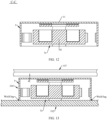
- FIG. 13 is a schematic diagram of a relative position between the vibration motor 104 shown in FIG. 10 to FIG. 12 and both the first middle frame 102 and the second screen 107 when the vibration motor is used in the foldable phone 203 shown in FIG. 7 .
- the edge of the housing 1 at the opening 1a is welded to the first middle frame 102.
- a weld leg is located at an included angle between an outer surface of the edge of the housing at the opening 1a and the first middle frame 102. Stability of welding is relatively high, so that connection stability of the vibration motor 104 on the first middle frame 102 can be improved.
- neither of a limiting structure and a buffer material layer needs to be disposed on a side that is of the housing 1 and that is away from the first middle frame 102, so that a mounting height of the vibration motor 104 on the first middle frame 102 can be reduced to some extent.
- FIG. 14 is a three-dimensional view of the vibration motor 104 according to some other embodiments of this application.
- FIG. 15 is a three-dimensional view of the vibration motor 104 in FIG. 14 from bottom to top.
- FIG. 16 is a schematic diagram of a cross-sectional structure of the vibration motor 104 in FIG. 14 on a line D-D.
- a connection lug 2 is disposed on an outer surface of the side frame 12 of the housing 1. The edge of the housing 1 at the opening 1a is fastened to the first middle frame 102 by using the connection lug 2.
- connection lugs 2 there are two connection lugs 2, and the two connection lugs 2 are respectively disposed on outer surfaces of two opposite side walls of the side frame 12. Specifically, referring to FIG. 15 , the two connection lugs 2 are respectively disposed on an outer surface of the third side wall 12c and an outer surface of the fourth side wall 12d. In some other embodiments, the two connection lugs 2 may be disposed on an outer surface of the first side wall 12a and an outer surface of the second side wall 12b. Because the two connection lugs 2 have a same structure, the following uses only one of the connection lugs 2 as an example to describe a structure of the connection lug 2. Specifically, referring to FIG. 14 to FIG.
- the connection lug 2 includes a fastening part 21, a lug part 22, and a connection hole 23.
- the fastening part 21 is welded to the outer surface of the side frame 12.
- the fastening part 21 may alternatively be sticked or clamped to the outer surface of the side frame 12, or the fastening part 21 and the side frame 12 are an integral structure.
- the lug part 22 is fastened to the fastening part 21.
- the lug part 22 and the fastening part 21 are an integral structure, that is, the lug part 22 and the fastening part 21 are an entire structure.
- the lug part 22 and the fastening part 21 may be formed separately and fastened together in a welding manner or the like.
- connection hole 23 is disposed on the lug part 22, and an axial direction of the connection hole 23 is consistent with an extension direction of a central axis (that is, an axis O in FIG. 16 ) of the opening 1a.
- the central axis of the opening 1a is an axis that passes through the center of the opening 1a and is perpendicular to the plane on which the opening 1a is located.
- the structure of the connection lug 2 is simple, and can implement a detachable connection between the edge of the housing 1 at the opening 1a and the first middle frame 102, to facilitate repair and replacement of the vibration motor 104. It should be noted that, when the edge of the housing 1 at the opening 1a is fastened to the first middle frame 102, the structure of the connection lug 2 may alternatively be another structure, for example, a buckle structure.
- FIG. 17 is a schematic diagram of a relative position between the vibration motor 104 shown in FIG. 14 to FIG. 16 and both the first middle frame 102 and the second screen 107 when the vibration motor is used in the foldable phone 203 shown in FIG. 7 .
- the edge of the housing 1 at the opening 1a is fastened to the first middle frame 102 by using two connection lugs 2.
- a connection member 00 penetrates the connection hole 23 of the connection lug 2, to fasten the connection lug 2 to the first middle frame 102.
- the connection member 00 includes but is not limited to a screw, a rivet, or a bolt.
- connection lug 2 Stability and reliability of this connection manner are relatively high, and neither of a limiting structure and a buffer material layer needs to be disposed on a side that is of the housing 1 and that is away from the first middle frame 102, so that a mounting height of the vibration motor 104 on the first middle frame 102 can be reduced to some extent.
- a region occupied by the connection lug 2 is relatively small, and space is reserved on a side that is of the lug part 22 and that is away from the first middle frame 102, so that other parts around the vibration motor can be accommodated.
- the vibration motor 104 and the second screen 107 are spaced from each other, and a width d of a gap between the vibration motor 104 and the second screen 107 is greater than or equal to 0.05 millimeters (mm), and is less than or equal to 0.35 mm. In some embodiments, the width d of the gap is greater than or equal to 0.1 mm, and is less than or equal to 0.2 mm.
- the width d of the gap may be 0.1 mm, 0.11 mm, 0.12 mm, 0.13 mm, 0.14 mm, 0.15 mm, 0.16 mm, 0.17 mm, 0.18 mm, 0.19 mm, 0.2 mm, or the like.
- the thickness of the foldable phone 203 can be reduced while the vibration motor 104 is prevented from impacting on the second screen 107.
- the vibration motor 104 is used in the tablet phone 100 shown in FIG. 2 or the foldable phone 200 shown in FIG.
- the vibration motor 104 and the first back cover 103 are also spaced from each other, and a width of a gap between the vibration motor 104 and the first back cover 103 may also be 0.05 mm to 0.35 mm. In some embodiments, the gap width may also be 0.1 mm to 0.2 mm.
- the edge of the housing 1 at the opening 1a may be fastened to the first middle frame 102 in a manner such as sticking or clamping. This is not specifically limited herein.
- a waterproof structure may be disposed between the edge of the housing 1 at the opening 1a and the first middle frame 102, to improve waterproof performance of the vibration motor 104.
- the waterproof structure includes but is not limited to a sealant and a sealing ring.
- the waterproof structure may alternatively be an annular groove disposed on the surface of the first middle frame 102, and the edge of the housing 1 at the opening 1a is embedded in the annular groove, so that a path on which moisture enters the housing 1 through the gap can be prolonged, thereby playing a waterproof role.
- the height (that is, a size in a thickness direction of the terminal device) of the vibration motor 104 is less than or equal to 3.0 mm.
- the height of the vibration motor 104 is 3.0 mm, 2.9 mm, 2.8 mm, 2.7 mm, 2.6 mm, 2.5 mm, or the like. In this way, the height of the vibration motor 104 is relatively small. This facilitates thinning of the terminal device.
- An internal structure of the vibration motor 104 shown in FIG. 10 to FIG. 12 is the same as an internal structure of the vibration motor 104 shown in FIG. 14 to FIG. 16 .
- the following uses only the vibration motor 104 shown in FIG. 14 to FIG. 16 as an example to describe the internal structure of the vibration motor 104.
- FIG. 18 is an exploded view of the vibration motor 104 shown in FIG. 14 .
- the vibration motor 104 further includes a mass block 3, an elastic assembly 4, a drive assembly 5, and an electrical connection structure 6.
- the mass block 3 is located in the housing 1.
- the mass block 3 is in a rectangular shape.
- the mass block 3 may alternatively be a cube, a sphere, an ellipsoid, or the like.
- the mass block 3 can reciprocally vibrate on a plane parallel to the plane on which the opening 1a is located.
- a vibration path of the mass block 3 may be a straight line, or may be a curve.
- a vibration path of the mass block 3 is a straight line.
- the vibration motor 104 is a lateral linear motor.
- a vibration direction of the mass block 3 is perpendicular to the thickness direction of the terminal device. This helps reduce the mounting height of the vibration motor 104 in the terminal device.
- the vibration direction of the mass block 3 may alternatively be perpendicular to the plane on which the opening 1a is located. In this way, the vibration motor 104 is a longitudinal linear motor.
- the vibration motor 104 is used in the terminal device, the vibration direction of the mass block 3 is consistent with the thickness direction of the terminal device.
- the vibration motor 104 may alternatively be a rotor motor. The following embodiments are all described on the basis that the vibration motor 104 is a lateral linear motor. This should not be considered as a special limitation on this application.
- the elastic assembly 4 is configured to elastically support the mass block 3 in the housing 1, and the elastic assembly 4 allows the mass block 3 to vibrate reciprocally in the housing 1 in a direction A1.
- the elastic assembly 4 includes a first elastic member 41 and a second elastic member 42. Both the first elastic member 41 and the second elastic member 42 are springs. An arrangement direction of the first elastic member 41, the mass block 3, and the second elastic member 42 is parallel to the vibration direction A1 of the mass block 3.
- the first elastic member 41 includes a first fastening part 41a, a first connection part 41c, and a second fastening part 41c that are connected in sequence.
- the first fastening part 41a is connected to the mass block 3, and a connection manner includes but is not limited to welding or sticking.
- the second fastening part 41c is connected to the fourth side wall 12d of the side frame 12 in the housing 1, and a connection manner includes but is not limited to welding or sticking.
- the first connection part 41c is approximately of an n shape, an arch direction A2 of the first connection part 41c is parallel to the plane on which the opening 1a is located, and the arch direction A2 of the first connection part 41c is perpendicular to the vibration direction A1 of the mass block 3.
- the second elastic member 42 includes a third fastening part 42a, a second connection part 42c, and a fourth fastening part 42c that are connected in sequence.
- the third fastening part 42a is connected to the mass block 3, and a connection manner includes but is not limited to welding or sticking.
- the fourth fastening part 42c is connected to the third side wall 12c of the side frame 12 in the housing 1, and a connection manner includes but is not limited to welding or sticking.
- the second connection part 42c is approximately of an n shape, and an arch direction A3 of the second connection part 42c is opposite to the arch direction A2 of the first connection part 41c.
- both the first elastic member 41 and the second elastic member 42 have a capability of deforming in a direction parallel to the vibration direction A1 of the mass block 3.
- an included angle between two arms of the first connection part 41c decreases, and an included angle between two arms of the second connection part 42c increases.
- an included angle between two arms of the first connection part 41c increases, and an included angle between two arms of the second connection part 42c decreases.
- the elastic assembly 4 can elastically support the mass block 3 in the housing 1, and the elastic assembly 4 allows the mass block 3 to reciprocally vibrate in the direction A1 in the housing 1, the elastic assembly 4 may alternatively be designed in another structural form. This is not specifically limited herein.
- the drive assembly 5 is configured to drive the mass block 3 to reciprocally vibrate on the plane parallel to the plane on which the opening 1a is located.
- the drive assembly 5 includes a magnet assembly 51 and a coil 52.
- the magnet assembly 51 is fastened to the mass block 3.
- a mounting groove (including a first mounting groove 31 and a second mounting groove 32) is disposed on the mass block 3, and the magnet assembly 51 is accommodated and secured in the mounting groove.
- the magnet assembly 51 may alternatively be disposed on an outer surface of the mass block 3.
- the coil 52 is fastened to the housing 1.
- the coil 52 is fastened to the inner surface of the top wall 11.
- a support structure of the coil 52 does not need to be additionally disposed. This helps reduce the height of the vibration motor 104.
- the magnet assembly 51 cooperates with the coil 52 to generate a Lorentz force, and the Lorentz force can drive the mass block 3 to reciprocally vibrate on the plane parallel to the plane on which the opening 1a is located.
- the magnet assembly 51 includes a first magnet 51a and a second magnet 51b.
- the first magnet 51a is housed in the first mounting groove 31, and the second magnet 51b is housed in the second mounting groove 32.
- the first magnet 51a and the second magnet 51b may be magnetic iron or magnetic steel.
- a magnetization direction of the first magnet 51a and a magnetization direction of the second magnet 5 1b are both perpendicular to the plane on which the opening 1a is located, and the magnetization direction of the first magnet 51a is opposite to the magnetization direction of the second magnet 51b.
- the magnetization direction is a direction from the north pole (that is, the N pole) to the south pole (that is, the S pole).
- the north pole that is, the N pole
- south pole that is, the S pole
- an upper end of the first magnet 51a is the S pole and a lower end is the N pole
- an upper end of the second magnet 5 1b is the N pole and a lower end is the S pole
- the upper end of the first magnet 51a may be the N pole and the lower end is the S pole
- the upper end of the second magnet 51b is the S pole and the lower end is the N pole.
- the coil 52 has a first side 52a and a second side 52b. Both an extension direction of the first side 52a and an extension direction of the second side 52b are perpendicular to the direction A1, the first magnet 51a is opposite the first side 52a, and the second magnet 51b is opposite the second side 52b.
- the first magnet 51a and the second magnet 51b When the coil 52 is powered on, the first magnet 51a and the second magnet 51b generate Lorentz forces F1 and F2 parallel to the direction A1, and a direction of F1 is the same as a direction of F2.
- a combined force of F1 and F2 may drive the mass block 3 to move unidirectionally on the plane parallel to the plane on which the opening 1a is located. Based on this, reciprocal vibration of the mass block 3 may be driven by current commutation of the coil 52.
- the magnet assembly 51 may alternatively include only one of the first magnet 51a and the second magnet 51b, and then one of F1 and F2 drives the mass block 3 to move on the plane parallel to the plane on which the opening 1a is located.
- a disposing position of the magnet assembly 51 may be interchangeable with a disposing position of the coil 52. That is, the magnet assembly 51 is disposed on the housing 1, and the coil 52 is disposed on the mass block 3.
- the electrical connection structure 6 is configured to lead an electrode of the coil 52 out of the housing 1.
- the electrical connection structure 6 includes but is not limited to a printed circuit board (printed circuit board, PCB), a flexible printed circuit (flexible printed circuit board, FPC), and a structure formed by connecting a plurality of wires by using a flexible structure.
- the electrical connection structure 6 includes a first segment 61, a second segment 62, and a third segment 63 that are sequentially connected.
- FIG. 19 is a schematic diagram of a cross-sectional structure of the vibration motor 104 in FIG. 14 on a line E-E. With reference to FIG.
- the first segment 61 is fastened to the inner surface of the top wall 11, and the coil 52 is fastened to the first segment 61 and electrically connected to the first segment 61.
- the second segment 62 is fastened to the inner surface of the side frame 12. Specifically, the second segment 62 may be fastened to an inner surface of the first side wall 12a in the side frame 12. In this way, the first elastic member 41 and the second elastic member 42 can be avoided, to avoid interference between the electrical connection structure 6 and the elastic member 4. In some other embodiments, the second segment 62 may alternatively be fastened to an inner surface of the second side wall 12b in the side frame 12.
- An extension path of the third segment 63 is parallel to the plane on which the opening 1a is located, and a part of the third segment 63 is located outside the housing 1.
- a positive terminal 63a and a negative terminal 63b are disposed on the part that is of the third segment 63 and that is located outside the housing 1.
- the electrical connection structure 6 can lead an electrode of the coil 52 to the third segment 63 outside the housing 1, and when the vibration motor 104 is used in the terminal device, the third segment 63 of the electrical connection structure 6 can be fastened and supported by using the first middle frame 102. That is, when the vibration motor 104 is used in the terminal device, the third segment 63 of the electrical connection structure 6 is attached to and fastened to the first middle frame 102. Therefore, the third segment 63 is fastened and supported by using the first middle frame 102.
- an avoidance notch 1b is disposed at the edge of the housing 1 at the opening 1a, and the third segment 63 penetrates into the avoidance notch 1b.
- the third segment 63 is prevented from being highly overlapped with the housing 1, so that a large gap exists between the edge of the housing 1 at the opening 1a and the first middle frame 102, thereby improving waterproof and sealing performance of the vibration motor 104.
- vibration motors 104 there may be one or more vibration motors 104 disposed in the terminal device 100. This is not specifically limited herein.
- a plurality of vibration motors 104 may all be disposed in the first accommodation space C1 or may all be disposed in the second accommodation space C2, or some vibration motors 104 may be disposed in the first accommodation space C1 and the other vibration motors 104 may be disposed in the second accommodation space C2.
- a disposing position of the vibration motors in the first accommodation space C1 and a disposing position of the vibration motors in the second accommodation space C2 may be symmetrical with respect to a rotation axis of the rotation mechanism 108.
- the two disposing positions may alternatively be asymmetrical. This is not specifically limited herein.
- the vibration motor 104 may be sold, stored, transported, or the like as a product structure. Based on this, to avoid a problem of jamming and rusting of the vibration motor 104 caused when dust enters the vibration motor 104 during transportation, storage, and sale, in some embodiments, refer to FIG. 20 and FIG. 21 .
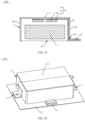
- FIG. 20 is a schematic diagram of a structure of the vibration motor 104 according to some other embodiments of this application.
- FIG. 21 is a schematic diagram of a cross-sectional structure of the vibration motor 104 in FIG. 20 on a line F-F.
- a removable dustproof structure 01 is disposed at the opening 1a.
- the dustproof structure 01 includes but is not limited to gummed paper, a steel plate, a plastic board, or the like.
- the dustproof structure 01 may be sticked to the edge of the housing 1 at the opening 1a, or may be disposed at the edge of the housing 1 at the opening 1a in a detachable connection manner such as threaded connection or clamping.
- the dustproof structure 01 is gummed paper.
- the gummed paper has low costs and high removal efficiency, and is easy to operate.
- the gummed paper has specific waterproof performance, and can prevent moisture from entering the vibration motor 104. Before the vibration motor 104 is assembled to the terminal device, the dustproof structure 01 may be removed.
- this application provides a vibration motor and a terminal device with the vibration motor.
- the vibration motor can vibrate to prompt a user to view in a timely manner.
- the vibration motor can vibrate to implement a tactile feedback.
Landscapes
- Engineering & Computer Science (AREA)
- Signal Processing (AREA)
- Power Engineering (AREA)
- Telephone Set Structure (AREA)
Abstract
Description
- This application claims priority to
Chinese Patent Application No. 202111278350.0, filed with the China National Intellectual Property Administration on October 30, 2021 - This application relates to the field of terminal device technologies, and in particular, to a vibration motor and a terminal device with a vibration motor.
- In a terminal device such as a mobile phone, a tablet, or a wearable device, vibration is usually generated by using a vibration motor, to implement functions such as an incoming call or SMS message reminder and a vibration tactile feedback. With the advance in science and technology, terminal devices gradually become thin. Especially, for a foldable phone, a thickness of the entire phone urgently needs to be reduced. Consequently, mounting space of a vibration motor in the terminal device is gradually reduced. However, because of a limitation of a condition of the vibration motor, thinning of the vibration motor causes vibration performance reduction. Therefore, a current thickness of the vibration motor becomes one of bottlenecks that impede further thinning of the terminal device. It can be learned that how to reduce a thickness of a terminal device (especially a foldable phone) without sacrificing performance of a vibration motor becomes a current design difficulty.
- Embodiments of this application provide a vibration motor and a terminal device, to reduce a thickness of a terminal device without sacrificing performance of a vibration motor.
- To achieve the foregoing objective, the following technical solutions are used in embodiments of this application.
- According to a first aspect, a terminal device is provided. The terminal device includes a first screen, a first middle frame, and a vibration motor. At least a part of the first screen is located on one side of the first middle frame and is stacked with the first middle frame. The vibration motor is located on a side that is of the first middle frame and that is away from the at least part of the first screen. The vibration motor includes a housing, one end of the housing is opened to form an opening, the opening faces the first middle frame, and an edge of the housing at the opening is fastened to the first middle frame.
- In the terminal device provided in this application, the opening on the housing of the vibration motor is blocked by using the first middle frame, to form a closed housing, thereby achieving a waterproof and dustproof protection function to some extent. In addition, the first middle frame forms a wall plate of the housing of the vibration motor. Without changing a height of internal accommodation space of the vibration motor, a height of the vibration motor can be reduced, to reduce a mounting height of the vibration motor in the terminal device. This helps reduce a thickness of the terminal device. Because the height of the internal accommodation space of the vibration motor is unchanged, a design height of a structure such as a mass block in the housing does not need to be limited, so that performance of the vibration motor can be ensured.
- In a possible implementation of the first aspect, the housing includes a top wall and a side frame, the side frame is disposed around a circumference of the top wall, and an end that is of the side frame and that is away from the top wall surrounds the opening. The structure of the housing is simple, and the top wall and the side frame may be formed integrally by using a stamping process. In some other embodiments, the top wall and the side frame may be formed separately and assembled together. This can facilitate assembly of an internal structure.
- In a possible implementation of the first aspect, the vibration motor further includes a mass block. The mass block is disposed in the housing, and the mass block can reciprocally vibrate relative to the housing on a plane parallel to a plane on which the opening is located. Specifically, on the plane parallel to the plane on which the opening is located, a vibration path of the mass block may be a straight line, or may be a curve. A vibration direction of the mass block is perpendicular to a thickness direction of the terminal device. This helps reduce a thickness of the vibration motor, and helps reduce a mounting height of the vibration motor in the terminal device.
- In a possible implementation of the first aspect, an elastic assembly is configured to elastically support the mass block in the housing, and the elastic assembly allows the mass block to vibrate reciprocally in the housing. In this way, vibration stability of the mass block can be ensured.
- In a possible implementation of the first aspect, the elastic assembly includes a first elastic member and a second elastic member. Both the first elastic member and the second elastic member are springs. An arrangement direction of the first elastic member, the mass block, and the second elastic member is parallel to the vibration direction of the mass block. The first elastic member includes a first fastening part, a first connection part, and a second fastening part that are connected in sequence. The first fastening part is connected to the mass block, and a connection manner includes but is not limited to welding, sticking, or integral molding. The second fastening part is connected to the side frame of the housing, and a connection manner includes but is not limited to welding, sticking, or integral molding. The first connection part is approximately of an n shape, an arch direction of the first connection part is parallel to the plane on which the opening is located, and the arch direction of the first connection part is perpendicular to the vibration direction of the mass block. The second elastic member includes a third fastening part, a second connection part, and a fourth fastening part that are connected in sequence. The third fastening part is connected to the mass block, and a connection manner includes but is not limited to welding or sticking. The fourth fastening part is connected to the side frame of the housing, and a connection manner includes but is not limited to welding or sticking. The second connection part is approximately of an n shape, and an arch direction of the second connection part is opposite to the arch direction of the first connection part. In this way, both the first elastic member and the second elastic member have a capability of deforming in a direction parallel to the vibration direction of the mass block. This structure is simple and easy to implement.
- In a possible implementation of the first aspect, the vibration motor further includes a drive assembly. The drive assembly includes a magnet assembly and a coil. The magnet assembly is fastened to the mass block, the coil is located between the mass block and the top wall, the coil is fastened to the top wall of the housing, the magnet assembly cooperates with the coil to generate a Lorentz force, and the Lorentz force is used to drive the mass block to reciprocally vibrate relative to the housing on the plane parallel to the plane on which the opening is located. A structure of the drive assembly is simple, and the magnet assembly may alternatively participate in vibration as a part of the mass block. In addition, because the coil is fastened to the top wall of the housing, a layout is proper, and a support structure of the coil does not need to be additionally disposed. This helps reduce a height of the vibration motor.
- In a possible implementation of the first aspect, the vibration motor further includes an electrical connection structure. The electrical connection structure includes a first segment, a second segment, and a third segment that are sequentially connected. The first segment is fastened to an inner surface of the top wall, the coil is fastened to the first segment and electrically connected to the first segment, the second segment is fastened to an inner surface of the side frame, the third segment extends in a radial direction of the opening, a part of the third segment is located outside the housing, and a positive terminal and a negative terminal are disposed on the part that is of the third segment and that is located outside the housing. The electrical connection structure can lead an electrode of the coil to the third segment outside the housing, and when the vibration motor is used in the terminal device, the third segment of the electrical connection structure can be fastened and supported by using the first middle frame. That is, when the vibration motor is used in the terminal device, the third segment of the electrical connection structure is attached to and fastened to the first middle frame. Therefore, the third segment is fastened and supported by using the first middle frame.
- In a possible implementation of the first aspect, the electrical connection structure is a flexible circuit board.
- In a possible implementation of the first aspect, a connection lug is disposed on an outer surface of the side frame, and the edge of the housing at the opening is fastened to the first middle frame by using the connection lug. Stability and reliability of this connection manner are relatively high, and neither of a limiting structure and a buffer material layer needs to be disposed on a side that is of the housing and that is away from the first middle frame, so that a mounting height of the vibration motor on the first middle frame can be reduced to some extent. In addition, a region occupied by the connection lug is relatively small, and space is reserved on a side that is of the lug and that is away from the first middle frame, so that other parts around the vibration motor can be accommodated.
- In a possible implementation of the first aspect, the connection lug includes a fastening part, a lug part, and a connection hole, the fastening part is fastened to the outer surface of the side frame, the lug part is fastened to the fastening part, the connection hole is disposed in the lug part, and an axial direction of the connection hole is consistent with an extension direction of a central axis of the opening. This structure is simple, and can implement a detachable connection between the edge of the housing at the opening and the first middle frame, to facilitate repair and replacement.
- In a possible implementation of the first aspect, the edge of the housing at the opening is welded to the first middle frame. Stability of welding is relatively high, so that connection stability of the vibration motor on the first middle frame can be improved. In addition, neither of a limiting structure and a buffer material layer needs to be disposed on a side that is of the housing and that is away from the first middle frame, so that a mounting height of the vibration motor on the first middle frame can be reduced to some extent.
- In a possible implementation of the first aspect, the first screen includes a first part and a second part, and the first part of the first screen is located on one side of the first middle frame and is stacked with the first middle frame. The terminal device further includes a second middle frame, where the second middle frame is rotatably connected to the first middle frame, the second part is disposed on one side of the second middle frame and is stacked with the second middle frame, the terminal device can change between an unfolded state and a folded state, and when the terminal device is in the unfolded state, the first part of the first screen and the second part of the first screen face a same side, or when the terminal device is in the folded state, the first part of the first screen and the second part of the first screen face each other or back onto each other. In this way, the terminal device is a foldable terminal device, and a wall plate of the housing of the vibration motor is formed by using the first middle frame. Without changing a height of internal accommodation space of the vibration motor, a height of the vibration motor can be reduced. This helps reduce a thickness of the foldable terminal device, to improve a hand feeling, a texture, and portability of the foldable terminal.
- In a possible implementation of the first aspect, when the terminal device is in the folded state, the first part of the first screen and the second part of the first screen face each other. The terminal device further includes a second screen, where the second screen is located on a side that is of the vibration motor and that is away from the first middle frame, the second screen and the first middle frame are relatively fastened, and the vibration motor and the second screen are spaced from each other. In this way, the terminal device is an inward-foldable terminal having two screens, and a wall plate of the housing of the vibration motor is formed by using the first middle frame. Without changing a height of internal accommodation space of the vibration motor, a height of the vibration motor can be reduced. This helps reduce a thickness of the foldable terminal device, to improve a hand feeling, a texture, and portability of the foldable terminal.
- In a possible implementation of the first aspect, a gap between the vibration motor and the second screen is 0.05 millimeters to 0.35 millimeters. In some embodiments, a width of the gap is 0.1 millimeters to 0.2 millimeters. The gap width is suitable, so that a thickness of the foldable terminal can be reduced while preventing the vibration motor from impacting on the second screen.
- In a possible implementation of the first aspect, a height of the vibration motor is less than or equal to 3.0 millimeters. In this way, the height of the vibration motor is relatively small. This facilitates a thinning design of the terminal device.
- In a possible implementation of the first aspect, there may be one or more vibration motors disposed in the terminal device. When the terminal device is a foldable terminal device, a plurality of vibration motors may all be disposed in first accommodation space of the terminal device or may all be disposed in second accommodation space of the terminal device, or some vibration motors may be disposed in the first accommodation space and the other vibration motors may be disposed in the second accommodation space. When some of a plurality of vibration motors are disposed in the first accommodation space and the other vibration motors are disposed in the second accommodation space, a disposing position of the vibration motors in the first accommodation space and a disposing position of the vibration motors in the second accommodation space may be symmetrical with respect to a rotation axis of a rotation mechanism.
- According to a second aspect, a vibration motor is provided. The vibration motor includes a housing, and one end of the housing is opened to form an opening.
- When the vibration motor provided in this application is used in a terminal device, the vibration motor may be disposed on a side that is of a first middle frame and that is away from a first screen, the opening of the housing of the vibration motor faces the first middle frame, and an edge of the housing at the opening is fastened to the first middle frame. In this way, the opening on the housing of the vibration motor is blocked by using the first middle frame, to form a closed housing, thereby achieving a waterproof and dustproof protection function to some extent. In addition, the first middle frame forms a wall plate of the housing of the vibration motor. Without changing a height of internal accommodation space of the vibration motor, a height of the vibration motor can be reduced, to reduce a mounting height of the vibration motor in the terminal device. This helps reduce a thickness of the terminal device. Because the height of the internal accommodation space of the vibration motor is unchanged, a design height of a structure such as a mass block in the housing does not need to be limited, so that performance of the vibration motor can be ensured.
- In a possible implementation of the second aspect, the housing includes a top wall and a side frame, the side frame is disposed around a circumference of the top wall, and an end that is of the side frame and that is away from the top wall surrounds the opening. The structure of the housing is simple, and the top wall and the side frame may be formed integrally by using a stamping process. In some other embodiments, the top wall and the side frame may be formed separately and assembled together. This can facilitate assembly of an internal structure.
- In a possible implementation of the second aspect, a connection lug is disposed on an outer surface of the side frame, the connection lug includes a fastening part, a lug part, and a connection hole, the fastening part is fastened to the outer surface of the side frame, the lug part is fastened to the fastening part, the connection hole is disposed in the lug part, and an axial direction of the connection hole is consistent with an extension direction of a central axis of the opening. This structure is simple, and can implement a detachable connection between the edge of the housing at the opening and the first middle frame, to facilitate repair and replacement.
- In a possible implementation of the second aspect, a removable dustproof structure covers the opening. This can avoid a problem of jamming and rusting of the vibration motor caused when dust enters the vibration motor during transportation, storage, and sale of the vibration motor.
- In a possible implementation of the second aspect, the dustproof structure is gummed paper. The gummed paper has low costs and high removal efficiency, and is easy to operate. In addition, the gummed paper has specific waterproof performance, and can prevent moisture from entering the vibration motor.
-
-
FIG. 1 is a schematic diagram of a structure of a terminal device according to some embodiments of this application; -
FIG. 2 is a schematic diagram of a cross-sectional structure of the terminal device inFIG. 1 on a line A-A; -
FIG. 3 is a schematic diagram of a structure of a terminal device according to some other embodiments of this application; -
FIG. 4 is a schematic diagram of a cross-sectional structure of the terminal device inFIG. 3 on a line B-B; -
FIG. 5 is a schematic diagram of a structure of an inward-foldable phone during folding from an unfolded state to a folded state according to some embodiments of this application, where (a) inFIG. 5 is a schematic diagram of a structure of the inward-foldable phone in the unfolded state, (b) inFIG. 5 is a schematic diagram of a structure of the inward-foldable phone in a half-folded state, and (c) inFIG. 5 is a schematic diagram of a structure of the inward-foldable phone in the folded state; -
FIG. 6 is a schematic diagram of a structure of an outward-foldable phone during folding from an unfolded state to a folded state according to some embodiments of this application, where (a) inFIG. 6 is a schematic diagram of a structure of the outward-foldable phone in the unfolded state, (b) inFIG. 6 is a schematic diagram of a structure of the outward-foldable phone in a half-folded state, and (c) inFIG. 6 is a schematic diagram of a structure of the outward-foldable phone in the folded state; -
FIG. 7 is a schematic diagram of a cross-sectional structure of a foldable phone according to some other embodiments of this application; -
FIG. 8 is a schematic diagram of a structure of the foldable phone inFIG. 7 during folding from an unfolded state to a folded state, where (a) inFIG. 8 is a schematic diagram of a structure of the foldable phone inFIG. 7 in the unfolded state, (b) inFIG. 8 is a schematic diagram of a structure of the foldable phone inFIG. 7 in a half-folded state, and (c) inFIG. 8 is a schematic diagram of a structure of the foldable phone inFIG. 7 in the folded state; -
FIG. 9 is a schematic diagram of an assembly structure between a vibration motor and both a first middle frame and a second screen in the foldable phone shown inFIG. 7 ; -
FIG. 10 is a three-dimensional view of a vibration motor according to some embodiments of this application; -
FIG. 11 is a three-dimensional view of the vibration motor inFIG. 10 from bottom to top; -
FIG. 12 is a schematic diagram of a cross-sectional structure of the vibration motor inFIG. 10 on a line C-C; -
FIG. 13 is a schematic diagram of a relative position between the vibration motor shown inFIG. 10 to FIG. 12 and both a first middle frame and a second screen when the vibration motor is used in the foldable phone shown inFIG. 7 ; -
FIG. 14 is a three-dimensional view of a vibration motor according to some other embodiments of this application; -
FIG. 15 is a three-dimensional view of the vibration motor inFIG. 14 from bottom to top; -
FIG. 16 is a schematic diagram of a cross-sectional structure of the vibration motor inFIG. 14 on a line D-D; -
FIG. 17 is a schematic diagram of a relative position between the vibration motor shown inFIG. 14 to FIG. 16 and both a first middle frame and a second screen when the vibration motor is used in the foldable phone shown inFIG. 7 ; -
FIG. 18 is an exploded view of the vibration motor shown inFIG. 14 ; -
FIG. 19 is a schematic diagram of a cross-sectional structure of the vibration motor inFIG. 14 on a line E-E; -
FIG. 20 is a schematic diagram of a structure of a vibration motor according to some other embodiments of this application; and -
FIG. 21 is a schematic diagram of a cross-sectional structure of the vibration motor inFIG. 20 on a line F-F. - In embodiments of this application, the terms "first" and "second" are merely used for description, but should not be understood as indicating or implying relative importance or implying a quantity of indicated technical features. Therefore, a feature limited by "first" or "second" may explicitly or implicitly include one or more features.
- In embodiments of this application, the term "include", "have", or any other variant thereof is intended to cover non-exclusive inclusion, so that a process, method, article, or apparatus that includes a series of elements includes not only those elements but also other elements that are not explicitly listed, or includes elements inherent to such a process, method, article, or apparatus. In a case without more restrictions, for an element limited by the statement "include a...", a process, method, article, or apparatus that includes the element may further include another same element.
- In embodiments of this application, position relationship qualifiers such as the terms "parallel", "perpendicular", "consistent", and "opposite" all indicate approximate positions that allow a specific error.
- This application provides a terminal device, and the terminal device has a display interface and can display a video or an image. In addition, a vibration motor is disposed in the terminal device, and can vibrate to implement functions such as an incoming call, message, SMS message, weather, or news reminder and a tactile feedback of a touch or an accidental touch. To overcome a technical bottleneck that a vibration motor limits further thinning of a terminal device, in this application, a middle frame in the terminal device is used to form a wall plate of a housing of the vibration motor, to reduce a mounting height of the vibration motor in the terminal device while ensuring internal accommodation space of the vibration motor, so as to reduce a thickness of the terminal device. Because the improvement solution in this application can ensure the internal accommodation space of the vibration motor, a design volume of a structure such as a mass block in the housing does not need to be limited, so that performance of the vibration motor can be ensured. It may be understood that the thickness of the terminal device refers to a size of the terminal device in a direction perpendicular to the display interface.
- The terminal device provided in this application includes but is not limited to a tablet terminal and a foldable terminal. The tablet terminal includes but is not limited to a tablet phone, a tablet personal computer (tablet personal computer), a tablet laptop computer (laptop computer), a tablet personal digital assistant (personal digital assistant, PDA), a tablet in-vehicle device, a tablet wearable device, or the like. The foldable terminal includes but is not limited to a foldable phone or a foldable computer.
- The following separately uses a tablet phone and a foldable phone as examples to analyze a thinning requirement for the terminal device, and describes how a vibration motor impedes thinning of the terminal device in this requirement.
-
FIG. 1 is a schematic diagram of a structure of a terminal device according to some embodiments of this application.FIG. 2 is a schematic diagram of a cross-sectional structure of the terminal device inFIG. 1 on a line A-A. In this embodiment, the terminal device is atablet phone 100. Thetablet phone 100 includes afirst screen 101, a firstmiddle frame 102, afirst back cover 103, and avibration motor 104. Thefirst screen 101 is located on one side of the firstmiddle frame 102 and is stacked with the firstmiddle frame 102. Thefirst back cover 103 is located on a side that is of the firstmiddle frame 102 and that is away from thefirst screen 101, and is stacked with the firstmiddle frame 102. First accommodation space C1 is formed between thefirst back cover 103 and the firstmiddle frame 102. Thevibration motor 104 is located in the first accommodation space C1, and thevibration motor 104 is fastened to the firstmiddle frame 102. Specifically, thevibration motor 104 may be glued to the firstmiddle frame 102, or may be fastened to the firstmiddle frame 102 in a manner such as clamping or threaded connection. - To ensure a hand feeling, a texture, and portability of the
tablet phone 100, a thickness of thetablet phone 100 needs to be reduced. On a premise that thicknesses of thefirst screen 101, the firstmiddle frame 102, and thefirst back cover 103 are fixed, a mounting height h of thevibration motor 104 on the firstmiddle frame 102 is one of bottlenecks that impede further thinning of thetablet phone 100. The mounting height h of thevibration motor 104 on the firstmiddle frame 102 is a height by which an entirety including thevibration motor 104 and a connection structure protrudes from the firstmiddle frame 102. The connection structure is a structure for connecting thevibration motor 104 to the firstmiddle frame 102. -
FIG. 3 is a schematic diagram of a structure of a terminal device according to some other embodiments of this application.FIG. 4 is a schematic diagram of a cross-sectional structure of the terminal device inFIG. 3 on a line B-B. In this embodiment, the terminal device is afoldable phone 200. In addition to thefirst screen 101, the firstmiddle frame 102, thefirst back cover 103, and thevibration motor 104, thefoldable phone 200 further includes a secondmiddle frame 105 and asecond back cover 106. - The first
middle frame 102 is rotatably connected to the secondmiddle frame 105. Specifically, referring toFIG. 4 , the firstmiddle frame 102 and the secondmiddle frame 105 may be rotatably connected by using arotation mechanism 108. There are a plurality of structural forms of therotation mechanism 108, provided that a rotatable connection between the firstmiddle frame 102 and the secondmiddle frame 105 can be implemented. This is not limited in this application, and details are not described. - The
first screen 101 may be folded into afirst part 101a (that is, a screen A) and asecond part 101b (that is, a screen B). A folding axis is formed between thefirst part 101a and thesecond part 101b. To enable thefirst screen 101 to be folded into thefirst part 101a and thesecond part 101b, at least a region in which the folding axis is located on thefirst screen 101 is made of a flexible material. A remaining region on thefirst screen 101 may be made of a flexible material, or may be made of a rigid material, or may be partially made of a rigid material and partially made of a flexible material. This is not specifically limited herein. In some embodiments, the entirefirst screen 101 is made of a flexible material. In this way, manufacturing is convenient and costs are relatively low. However, a screen made of the flexible material is easily scratched. - The
first part 101a is located on one side of the firstmiddle frame 102 and is stacked with the firstmiddle frame 102. Thesecond part 101b is located on one side of the secondmiddle frame 105 and is stacked with the secondmiddle frame 105. - The
second back cover 106 is located on a side that is of the secondmiddle frame 105 and that is away from thesecond part 101b, and is stacked with the secondmiddle frame 105. Second accommodation space C2 is formed between thefirst back cover 103 and the secondmiddle frame 105. The second accommodation space C2 is configured to accommodate structures such as a battery, a main board, and a camera module. - The
foldable phone 200 can change between an unfolded state and a folded state. Thefoldable phone 200 may be classified into two types based on folding directions from the unfolded state to the folded state. One type is a foldable phone that is folded inward (briefly referred to as an inward-foldable phone below), and the other type is a foldable phone that is folded outward (briefly referred to as an outward-foldable phone below). When the inward-foldable phone is in a folded state, thefirst part 101a and thesecond part 101b face each other. When the outward-foldable phone is in a folded state, thefirst part 101a and thesecond part 101b back onto each other. -
FIG. 5 is a schematic diagram of a structure of an inward-foldable phone 201 during folding from an unfolded state to a folded state according to some embodiments of this application. Specifically, (a) inFIG. 5 is a schematic diagram of a structure of the inward-foldable phone in the unfolded state. In this state, thefirst part 101a (that is, the screen A) and thesecond part 101b (that is, the screen B) face or approximately face a same side. In addition, in this state, an included angle θ between thefirst part 101a and thesecond part 101b is 180° or approximately 180°, so that large-screen display can be implemented, to provide more abundant information for a user and bring better use experience to the user. - It should be noted that in descriptions of the foregoing embodiments and the following embodiments, the included angle θ between the
first part 101a and thesecond part 101b is an included angle between thefirst part 101a and thesecond part 101b on a display side of thefirst screen 101. The display side of thefirst screen 101 is a side on which thefirst screen 101 displays an image or a video. When the user is on the display side of thefirst screen 101, the user can view an image or a video displayed on thefirst screen 101. - A schematic diagram of a structure of the inward-
foldable phone 201 in a half-folded state shown in (b) inFIG. 5 may be formed by folding two sides of the inward-foldable phone 201 in a direction a11 and a direction a12. In this state, the included angle θ between thefirst part 101a and thesecond part 101b is greater than 0° and less than 180°. Based on this, further, a schematic diagram of a structure of the inward-foldable phone 201 in the folded state shown in (c) inFIG. 5 may be formed by continuing to fold two sides of the inward-foldable phone 201 in a direction a13 and a direction a14. In this state, thefoldable phone 201 is completely folded, and thefirst part 101a and thesecond part 101b face each other, that is, the included angle θ between thefirst part 101a and thesecond part 101b is 0° or approximately 0°. In this state, thefirst screen 101 is invisible to the user. This can prevent thefirst screen 101 from being scratched by a hard object. -
FIG. 6 is a schematic diagram of a structure of an outward-foldable phone 202 during folding from an unfolded state to a folded state according to some embodiments of this application. Specifically, (a) inFIG. 6 is a schematic diagram of a structure of the outward-foldable phone 202 in the unfolded state. In this state, thefirst part 101a (that is, the screen A) and thesecond part 101b (that is, the screen B) face or approximately face a same side. In addition, in this state, an included angle θ between thefirst part 101a and thesecond part 101b is 180° or approximately 180°, so that large-screen display can be implemented, to provide more abundant information for a user and bring better use experience to the user. A schematic diagram of a structure of the outward-foldable phone in a half-folded state shown in (b) inFIG. 6 may be formed by folding two sides of the outward-foldable phone 202 in a direction a21 and a direction a22. In this state, the included angle θ between thefirst part 101a and thesecond part 101b is greater than 180° and less than 360°. Based on this, further, a schematic diagram of a structure of the outward-foldable phone 202 in the folded state shown in (c) inFIG. 6 may be formed by continuing to fold two sides of the outward-foldable phone 202 in a direction a23 and a direction a24. In this state, thefoldable phone 202 is completely folded, and thefirst part 101a and thesecond part 101b back onto each other, that is, the included angle θ between thefirst part 101a and thesecond part 101b is 360° or approximately 360°. In this state, a volume of the foldable phone is relatively small, and the foldable phone is easy to carry. In addition, small-screen display may be implemented by using one of thefirst part 101a and thesecond part 101b. However, because thefirst screen 101 is exposed to an external environment, thefirst screen 101 is prone to be scratched. - It should be noted that
FIG. 3 to FIG. 6 all show foldable phones that are folded horizontally. Certainly, the foldable phone in embodiments of this application may alternatively be a foldable phone that is folded vertically. This is not specifically limited herein. In addition, the foldable phone may not be the inward-foldable phone or the outward-foldable phone, but a foldable phone that supports both inward folding and outward folding. - Because a thickness of the foldable phone (including the inward-
foldable phone 201, the outward-foldable phone 202, and the foldable phone that supports both inward folding and outward folding) in the folded state is a sum of thicknesses of two folding parts, the thickness of the foldable phone in the folded state is approximately twice the thickness of thetablet phone 100 shown inFIG. 1 andFIG. 2 . Therefore, thefoldable phone 200 urgently needs to be thinned to improve a hand feeling, a texture, and portability. Therefore, compared with thetablet phone 100, thefoldable phone 200 more needs to be thinned by reducing the mounting height of thevibration motor 104 on the firstmiddle frame 102. -
FIG. 7 is a schematic diagram of a cross-sectional structure of afoldable phone 203 according to some other embodiments of this application. In addition to thefirst screen 101, the firstmiddle frame 102, thevibration motor 104, the secondmiddle frame 105, and thesecond back cover 106, thefoldable phone 203 further includes asecond screen 107. Thesecond screen 107 is located on a side that is of the firstmiddle frame 102 and that is away from thefirst screen 101, and is stacked with the firstmiddle frame 102. First accommodation space C1 is formed between thesecond screen 107 and the firstmiddle frame 102. Thevibration motor 104 is located in the first accommodation space C1, and thevibration motor 104 is fastened to the firstmiddle frame 102. -
FIG. 8 is a schematic diagram of a structure of thefoldable phone 203 inFIG. 7 during folding from an unfolded state to a folded state. Specifically, (a) inFIG. 8 is a schematic diagram of a structure of thefoldable phone 203 in the unfolded state. In this state, thefirst part 101a (that is, the screen A) and thesecond part 101b (that is, the screen B) face or approximately face a same side. In addition, in this state, an included angle θ between thefirst part 101a and thesecond part 101b is 180° or approximately 180°, so that large-screen display can be implemented, to provide more abundant information for a user and bring better use experience to the user. A schematic diagram of a structure of thefoldable phone 203 in a half-folded state shown in (b) inFIG. 8 may be formed by folding two sides of thefoldable phone 203 in a direction a31 and a direction a32. In this state, the included angle θ between thefirst part 101a and thesecond part 101b is greater than 0° and less than 180°. Based on this, further, a schematic diagram of a structure of thefoldable phone 203 in the folded state shown in (c) inFIG. 8 may be formed by continuing to fold two sides of thefoldable phone 203 in a direction a33 and a direction a34. In this state, thefoldable phone 203 is completely folded, and thefirst part 101a and thesecond part 101b face each other, that is, the included angle θ between thefirst part 101a and thesecond part 101b is 0° or approximately 0°. In this state, thefirst screen 101 is invisible to the user, so that thefirst screen 101 can be prevented from being scratched by a hard object. In addition, the second screen 107 (that is, a screen C) is exposed, so that small-screen display can be implemented by using thesecond screen 107. - In the foregoing embodiment, the
second screen 107 has scratch resistance performance, to reduce a possibility that thesecond screen 107 is scratched during small-screen display. For example, referring back toFIG. 7 , thesecond screen 107 includes atransparent cover plate 1071 and a display 1072 (English name: panel, also referred to as a display panel). Thetransparent cover plate 1071 is stacked with thedisplay 1072. Thedisplay 1072 may be a flexible display or a rigid display. For example, thedisplay 1072 may be an organic light-emitting diode (organic light-emitting diode, OLED) display, an active-matrix organic light-emitting diode (active-matrix organic light-emitting diode, AMOLED) display, a mini light-emitting diode (mini organic light-emitting diode) display, a micro light-emitting diode (micro organic light-emitting diode) display, a micro organic light-emitting diode (micro organic light-emitting diode) display, a quantum dot light-emitting diode (quantum dot light-emitting diodes, QLED) display, or a liquid crystal display (liquid crystal display, LCD). Thetransparent cover plate 1071 is mainly configured to protect thedisplay 1072 and prevent dust, thereby reducing a possibility that thesecond screen 107 is scratched. A material of thetransparent cover plate 1071 includes but is not limited to glass. - It may be understood that, on the premise that scratch resistance performance of the
second screen 107 is ensured, thesecond screen 107 may alternatively use another structural form. Details are not described herein. - On the premise that scratch resistance performance of the
second screen 107 is ensured, a thickness of thesecond screen 107 is usually large. The thickness of thesecond screen 107 with scratch resistance performance is usually greater than a thickness of the back cover. Specifically, compared with thefoldable phone 200 shown inFIG. 4 , thefoldable phone 203 shown inFIG. 7 is provided with thesecond screen 107, and the thickness of thesecond screen 107 is greater than the thickness of thefirst back cover 103 of thefoldable phone 201 shown inFIG. 4 . Therefore, the thickness of thefoldable phone 203 inFIG. 7 in the folded state is greater than the thickness of thefoldable phone 200 inFIG. 4 in the folded state. Therefore, thefoldable phone 203 shown inFIG. 7 more urgently needs to be thinned to improve a hand feeling, a texture, and portability. Therefore, compared with thefoldable phone 200 shown inFIG. 4 , thefoldable phone 203 shown inFIG. 7 more needs to be thinned by reducing the mounting height of thevibration motor 104 on the firstmiddle frame 102. - It may be learned from the foregoing description that the mounting height of the
vibration motor 104 on the firstmiddle frame 102 is one of the bottlenecks that impede thinning of the tablet phone and the foldable phone (especially the foldable phone with thefirst screen 101 and the second screen 107).FIG. 9 is a schematic diagram of an assembly structure between thevibration motor 104 and both the firstmiddle frame 102 and thesecond screen 107 in thefoldable phone 203 shown inFIG. 7 . Thevibration motor 104 includes ahousing 1, thehousing 1 is a closed housing, and a mass block of thevibration motor 104 is disposed in thehousing 1. Thehousing 1 is sticked to the firstmiddle frame 102 by using an adhesive 108. Based on this, to ensure connection stability of thehousing 1 on the firstmiddle frame 102, a limitingstructure 120 is further disposed on a side that is of thehousing 1 and that is away from the firstmiddle frame 102. The limitingstructure 102 is fixedly connected to the firstmiddle frame 102. The limitingstructure 102 is configured to prevent thehousing 1 from moving in a direction away from the firstmiddle frame 102. Based on this, to avoid falling off or damage of thesecond screen 107 caused when thevibration motor 104 impacts on thesecond screen 107 during vibration, abuffer material layer 109 is further disposed between the limitingstructure 102 and thesecond screen 107. Thebuffer material layer 109 includes but is not limited to foam and rubber. In this embodiment, the mounting height h of thevibration motor 104 on the firstmiddle frame 102 is a sum of the thickness of the adhesive 108, the height of thevibration motor 104, and the thickness of the limitingstructure 102, and the mounting height h is relatively large. This is not conducive to thinning of the entire phone. - To resolve the foregoing technical problem, a sinking groove may be disposed on a surface of the first
middle frame 102, and a part of thevibration motor 104 is accommodated in the sinking groove, to reduce the mounting height of thevibration motor 104 on the firstmiddle frame 102. However, with development of technologies, as one type ofvibration motor 104, a lateral linear motor is widely used in tablet terminal devices and foldable terminal devices. A length and a width of the lateral linear motor are usually large, and an occupation area on the firstmiddle frame 102 is relatively large. If a sinking groove is disposed on the firstmiddle frame 102 to reduce the mounting height of thevibration motor 104, an area of the sinking groove region needs to be large to accommodate the lateral linear motor. However, an increase in the area of the sinking groove region leads to a great decrease in structural strength and reliability of the firstmiddle frame 102. - To ensure reliability of the first
middle frame 102 and reduce the mounting height of thevibration motor 104 on the firstmiddle frame 102, refer toFIG. 10 to FIG. 12 .FIG. 10 is a three-dimensional view of thevibration motor 104 according to some embodiments of this application.FIG. 11 is a three-dimensional view of thevibration motor 104 inFIG. 10 from bottom to top.FIG. 12 is a schematic diagram of a cross-sectional structure of thevibration motor 104 inFIG. 10 on a line C-C. It should be noted that, in this embodiment, "line C-C" refers to a plane on which the line C-C and arrows at two ends of the line C-C are located. Descriptions of similar drawings below should be understood in a same manner, and details are not described below. Thevibration motor 104 can be used in the terminal device in any one of the foregoing embodiments. - Specifically, the
vibration motor 104 includes ahousing 1, and thehousing 1 is configured to perform waterproof and dustproof protection on an internal structure of thevibration motor 104. A material of thehousing 1 is metal, for example, stainless steel. In this way, on the premise that structural strength is ensured, a thickness of thehousing 1 may be designed to be relatively small, to help reduce a thickness and a volume of thevibration motor 104. In some embodiments, thehousing 1 is made of a metal material having magnetic shielding performance. In this way, thehousing 1 can prevent a magnetic field inside thevibration motor 104 from affecting performance of an antenna located around thevibration motor 104 in the terminal device. - One end of the
housing 1 is opened to form an opening 1a. In some embodiments, referring toFIG. 10 , thehousing 1 includes atop wall 11 and aside frame 12, and theside frame 12 is disposed around a circumference of thetop wall 11. Optionally, referring toFIG. 11 , theside frame 12 includes afirst side wall 12a and asecond side wall 12b that are disposed opposite each other, and athird side wall 12c and afourth side wall 12d that are disposed opposite each other. Theside frame 12 is formed by sequentially connecting thefirst side wall 12a, thethird side wall 12c, thesecond side wall 12b, and thefourth side wall 12d. The opening 1a is surrounded by an end that is of theside frame 12 and that is away from thetop wall 11. Specifically, referring toFIG. 11 , the opening 1a is surrounded by an end that is of thefirst side wall 12a and that is away from thetop wall 11, an end that is of thesecond side wall 12b and that is away from thetop wall 11, an end that is of thethird side wall 12c and that is away from thetop wall 11, and an end that is of thefourth side wall 12d and that is away from thetop wall 11. The structure of the housing is simple, and thetop wall 11 and theside frame 12 may be formed integrally by using a stamping process. In some other embodiments, thetop wall 11 and theside frame 12 may be formed separately and assembled together. This can facilitate assembly of an internal structure. - When the
vibration motor 104 is used in the terminal device described in any one of the foregoing embodiments, the opening 1a is opposite the firstmiddle frame 102, and an edge of thehousing 1 at the opening 1a is fastened to the firstmiddle frame 102. - In this way, when the
vibration motor 104 is used in the terminal device, the opening 1a of thevibration motor 104 may be blocked by using the firstmiddle frame 102, to form a closed housing, thereby achieving a waterproof and dustproof protection function to some extent. In addition, the firstmiddle frame 102 forms a wall plate of thehousing 1 of thevibration motor 104. Without changing a height of internal accommodation space of thevibration motor 104, a height of thevibration motor 104 can be reduced, to reduce a mounting height of thevibration motor 104 in the terminal device. This helps reduce a thickness of the terminal device. Because the height of the internal accommodation space of thevibration motor 104 is unchanged, a design height of a structure such as a mass block in thehousing 1 does not need to be limited, so that performance of thevibration motor 104 can be ensured. - There are a plurality of fastening manners between the edge of the
housing 1 at the opening 1a and the firstmiddle frame 102. - For example,
FIG. 13 is a schematic diagram of a relative position between thevibration motor 104 shown inFIG. 10 to FIG. 12 and both the firstmiddle frame 102 and thesecond screen 107 when the vibration motor is used in thefoldable phone 203 shown inFIG. 7 . In this embodiment, the edge of thehousing 1 at the opening 1a is welded to the firstmiddle frame 102. A weld leg is located at an included angle between an outer surface of the edge of the housing at the opening 1a and the firstmiddle frame 102. Stability of welding is relatively high, so that connection stability of thevibration motor 104 on the firstmiddle frame 102 can be improved. In addition, neither of a limiting structure and a buffer material layer needs to be disposed on a side that is of thehousing 1 and that is away from the firstmiddle frame 102, so that a mounting height of thevibration motor 104 on the firstmiddle frame 102 can be reduced to some extent. - For another example, refer to
FIG. 14 to FIG. 16 .FIG. 14 is a three-dimensional view of thevibration motor 104 according to some other embodiments of this application.FIG. 15 is a three-dimensional view of thevibration motor 104 inFIG. 14 from bottom to top.FIG. 16 is a schematic diagram of a cross-sectional structure of thevibration motor 104 inFIG. 14 on a line D-D. In this embodiment, aconnection lug 2 is disposed on an outer surface of theside frame 12 of thehousing 1. The edge of thehousing 1 at the opening 1a is fastened to the firstmiddle frame 102 by using theconnection lug 2. There is at least oneconnection lug 2. Specifically, there may be one, two, three, four, or more connection lugs 2. In the embodiments shown inFIG. 14 to FIG. 16 , there are two connection lugs 2, and the twoconnection lugs 2 are respectively disposed on outer surfaces of two opposite side walls of theside frame 12. Specifically, referring toFIG. 15 , the twoconnection lugs 2 are respectively disposed on an outer surface of thethird side wall 12c and an outer surface of thefourth side wall 12d. In some other embodiments, the twoconnection lugs 2 may be disposed on an outer surface of thefirst side wall 12a and an outer surface of thesecond side wall 12b. Because the twoconnection lugs 2 have a same structure, the following uses only one of the connection lugs 2 as an example to describe a structure of theconnection lug 2. Specifically, referring toFIG. 14 to FIG. 16 , theconnection lug 2 includes afastening part 21, alug part 22, and aconnection hole 23. Thefastening part 21 is welded to the outer surface of theside frame 12. In some other embodiments, thefastening part 21 may alternatively be sticked or clamped to the outer surface of theside frame 12, or thefastening part 21 and theside frame 12 are an integral structure. Thelug part 22 is fastened to thefastening part 21. Thelug part 22 and thefastening part 21 are an integral structure, that is, thelug part 22 and thefastening part 21 are an entire structure. In some other embodiments, thelug part 22 and thefastening part 21 may be formed separately and fastened together in a welding manner or the like. Theconnection hole 23 is disposed on thelug part 22, and an axial direction of theconnection hole 23 is consistent with an extension direction of a central axis (that is, an axis O inFIG. 16 ) of the opening 1a. The central axis of the opening 1a is an axis that passes through the center of the opening 1a and is perpendicular to the plane on which the opening 1a is located. The structure of theconnection lug 2 is simple, and can implement a detachable connection between the edge of thehousing 1 at the opening 1a and the firstmiddle frame 102, to facilitate repair and replacement of thevibration motor 104. It should be noted that, when the edge of thehousing 1 at the opening 1a is fastened to the firstmiddle frame 102, the structure of theconnection lug 2 may alternatively be another structure, for example, a buckle structure. -
FIG. 17 is a schematic diagram of a relative position between thevibration motor 104 shown inFIG. 14 to FIG. 16 and both the firstmiddle frame 102 and thesecond screen 107 when the vibration motor is used in thefoldable phone 203 shown inFIG. 7 . In this embodiment, the edge of thehousing 1 at the opening 1a is fastened to the firstmiddle frame 102 by using two connection lugs 2. Specifically, aconnection member 00 penetrates theconnection hole 23 of theconnection lug 2, to fasten theconnection lug 2 to the firstmiddle frame 102. Theconnection member 00 includes but is not limited to a screw, a rivet, or a bolt. Stability and reliability of this connection manner are relatively high, and neither of a limiting structure and a buffer material layer needs to be disposed on a side that is of thehousing 1 and that is away from the firstmiddle frame 102, so that a mounting height of thevibration motor 104 on the firstmiddle frame 102 can be reduced to some extent. In addition, a region occupied by theconnection lug 2 is relatively small, and space is reserved on a side that is of thelug part 22 and that is away from the firstmiddle frame 102, so that other parts around the vibration motor can be accommodated. - On the basis of the foregoing two examples, referring to
FIG. 13 orFIG. 17 , thevibration motor 104 and thesecond screen 107 are spaced from each other, and a width d of a gap between thevibration motor 104 and thesecond screen 107 is greater than or equal to 0.05 millimeters (mm), and is less than or equal to 0.35 mm. In some embodiments, the width d of the gap is greater than or equal to 0.1 mm, and is less than or equal to 0.2 mm. Specifically, the width d of the gap may be 0.1 mm, 0.11 mm, 0.12 mm, 0.13 mm, 0.14 mm, 0.15 mm, 0.16 mm, 0.17 mm, 0.18 mm, 0.19 mm, 0.2 mm, or the like. In this way, the thickness of thefoldable phone 203 can be reduced while thevibration motor 104 is prevented from impacting on thesecond screen 107. Similarly, when thevibration motor 104 is used in thetablet phone 100 shown inFIG. 2 or thefoldable phone 200 shown inFIG. 4 , thevibration motor 104 and thefirst back cover 103 are also spaced from each other, and a width of a gap between thevibration motor 104 and thefirst back cover 103 may also be 0.05 mm to 0.35 mm. In some embodiments, the gap width may also be 0.1 mm to 0.2 mm. - In some other examples, the edge of the
housing 1 at the opening 1a may be fastened to the firstmiddle frame 102 in a manner such as sticking or clamping. This is not specifically limited herein. - In some embodiments, a waterproof structure may be disposed between the edge of the
housing 1 at the opening 1a and the firstmiddle frame 102, to improve waterproof performance of thevibration motor 104. The waterproof structure includes but is not limited to a sealant and a sealing ring. The waterproof structure may alternatively be an annular groove disposed on the surface of the firstmiddle frame 102, and the edge of thehousing 1 at the opening 1a is embedded in the annular groove, so that a path on which moisture enters thehousing 1 through the gap can be prolonged, thereby playing a waterproof role. - In some embodiments, the height (that is, a size in a thickness direction of the terminal device) of the
vibration motor 104 is less than or equal to 3.0 mm. For example, the height of thevibration motor 104 is 3.0 mm, 2.9 mm, 2.8 mm, 2.7 mm, 2.6 mm, 2.5 mm, or the like. In this way, the height of thevibration motor 104 is relatively small. This facilitates thinning of the terminal device. - An internal structure of the
vibration motor 104 shown inFIG. 10 to FIG. 12 is the same as an internal structure of thevibration motor 104 shown inFIG. 14 to FIG. 16 . The following uses only thevibration motor 104 shown inFIG. 14 to FIG. 16 as an example to describe the internal structure of thevibration motor 104. - Specifically,
FIG. 18 is an exploded view of thevibration motor 104 shown inFIG. 14 . In addition to thehousing 1, thevibration motor 104 further includes amass block 3, anelastic assembly 4, adrive assembly 5, and anelectrical connection structure 6. - The
mass block 3 is located in thehousing 1. Themass block 3 is in a rectangular shape. In some other embodiments, themass block 3 may alternatively be a cube, a sphere, an ellipsoid, or the like. As a vibration body in thevibration motor 104, themass block 3 can reciprocally vibrate on a plane parallel to the plane on which the opening 1a is located. Specifically, on the plane parallel to the plane on which the opening 1a is located, a vibration path of themass block 3 may be a straight line, or may be a curve. In the embodiment shown inFIG. 18 , with reference toFIG. 15 andFIG. 16 , a vibration path of themass block 3 is a straight line. In this way, thevibration motor 104 is a lateral linear motor. When thevibration motor 104 is used in the terminal device, a vibration direction of themass block 3 is perpendicular to the thickness direction of the terminal device. This helps reduce the mounting height of thevibration motor 104 in the terminal device. In some other embodiments, the vibration direction of themass block 3 may alternatively be perpendicular to the plane on which the opening 1a is located. In this way, thevibration motor 104 is a longitudinal linear motor. When thevibration motor 104 is used in the terminal device, the vibration direction of themass block 3 is consistent with the thickness direction of the terminal device. In some other embodiments, thevibration motor 104 may alternatively be a rotor motor. The following embodiments are all described on the basis that thevibration motor 104 is a lateral linear motor. This should not be considered as a special limitation on this application. - The
elastic assembly 4 is configured to elastically support themass block 3 in thehousing 1, and theelastic assembly 4 allows themass block 3 to vibrate reciprocally in thehousing 1 in a direction A1. In some embodiments, referring toFIG. 18 , and with reference toFIG. 15 , theelastic assembly 4 includes a firstelastic member 41 and a secondelastic member 42. Both the firstelastic member 41 and the secondelastic member 42 are springs. An arrangement direction of the firstelastic member 41, themass block 3, and the secondelastic member 42 is parallel to the vibration direction A1 of themass block 3. - The first
elastic member 41 includes afirst fastening part 41a, afirst connection part 41c, and asecond fastening part 41c that are connected in sequence. Thefirst fastening part 41a is connected to themass block 3, and a connection manner includes but is not limited to welding or sticking. Thesecond fastening part 41c is connected to thefourth side wall 12d of theside frame 12 in thehousing 1, and a connection manner includes but is not limited to welding or sticking. Thefirst connection part 41c is approximately of an n shape, an arch direction A2 of thefirst connection part 41c is parallel to the plane on which the opening 1a is located, and the arch direction A2 of thefirst connection part 41c is perpendicular to the vibration direction A1 of themass block 3. - The second
elastic member 42 includes athird fastening part 42a, asecond connection part 42c, and afourth fastening part 42c that are connected in sequence. Thethird fastening part 42a is connected to themass block 3, and a connection manner includes but is not limited to welding or sticking. Thefourth fastening part 42c is connected to thethird side wall 12c of theside frame 12 in thehousing 1, and a connection manner includes but is not limited to welding or sticking. Thesecond connection part 42c is approximately of an n shape, and an arch direction A3 of thesecond connection part 42c is opposite to the arch direction A2 of thefirst connection part 41c. - In this way, both the first
elastic member 41 and the secondelastic member 42 have a capability of deforming in a direction parallel to the vibration direction A1 of themass block 3. When themass block 3 vibrates in a direction close to thefourth side wall 12d, an included angle between two arms of thefirst connection part 41c decreases, and an included angle between two arms of thesecond connection part 42c increases. When themass block 3 vibrates in a direction close to thethird side wall 12c, an included angle between two arms of thefirst connection part 41c increases, and an included angle between two arms of thesecond connection part 42c decreases. This structure is simple and easy to implement. - It should be noted that, when it is ensured that the
elastic assembly 4 can elastically support themass block 3 in thehousing 1, and theelastic assembly 4 allows themass block 3 to reciprocally vibrate in the direction A1 in thehousing 1, theelastic assembly 4 may alternatively be designed in another structural form. This is not specifically limited herein. - The
drive assembly 5 is configured to drive themass block 3 to reciprocally vibrate on the plane parallel to the plane on which the opening 1a is located. In some embodiments, referring toFIG. 18 and with reference toFIG. 16 , thedrive assembly 5 includes amagnet assembly 51 and acoil 52. Themagnet assembly 51 is fastened to themass block 3. In some embodiments, a mounting groove (including a first mountinggroove 31 and a second mounting groove 32) is disposed on themass block 3, and themagnet assembly 51 is accommodated and secured in the mounting groove. In some other embodiments, themagnet assembly 51 may alternatively be disposed on an outer surface of themass block 3. Thecoil 52 is fastened to thehousing 1. In some embodiments, thecoil 52 is fastened to the inner surface of thetop wall 11. In this way, a support structure of thecoil 52 does not need to be additionally disposed. This helps reduce the height of thevibration motor 104. Themagnet assembly 51 cooperates with thecoil 52 to generate a Lorentz force, and the Lorentz force can drive themass block 3 to reciprocally vibrate on the plane parallel to the plane on which the opening 1a is located. - Specifically, the
magnet assembly 51 includes afirst magnet 51a and asecond magnet 51b. Thefirst magnet 51a is housed in the first mountinggroove 31, and thesecond magnet 51b is housed in the second mountinggroove 32. Thefirst magnet 51a and thesecond magnet 51b may be magnetic iron or magnetic steel. A magnetization direction of thefirst magnet 51a and a magnetization direction of thesecond magnet 5 1b are both perpendicular to the plane on which the opening 1a is located, and the magnetization direction of thefirst magnet 51a is opposite to the magnetization direction of thesecond magnet 51b. The magnetization direction is a direction from the north pole (that is, the N pole) to the south pole (that is, the S pole). For example, referring toFIG. 18 and with reference toFIG. 16 , an upper end of thefirst magnet 51a is the S pole and a lower end is the N pole, and an upper end of thesecond magnet 5 1b is the N pole and a lower end is the S pole. In some other embodiments, the upper end of thefirst magnet 51a may be the N pole and the lower end is the S pole. Based on this, the upper end of thesecond magnet 51b is the S pole and the lower end is the N pole. Thecoil 52 has afirst side 52a and asecond side 52b. Both an extension direction of thefirst side 52a and an extension direction of thesecond side 52b are perpendicular to the direction A1, thefirst magnet 51a is opposite thefirst side 52a, and thesecond magnet 51b is opposite thesecond side 52b. When thecoil 52 is powered on, thefirst magnet 51a and thesecond magnet 51b generate Lorentz forces F1 and F2 parallel to the direction A1, and a direction of F1 is the same as a direction of F2. A combined force of F1 and F2 may drive themass block 3 to move unidirectionally on the plane parallel to the plane on which the opening 1a is located. Based on this, reciprocal vibration of themass block 3 may be driven by current commutation of thecoil 52. In some other embodiments, themagnet assembly 51 may alternatively include only one of thefirst magnet 51a and thesecond magnet 51b, and then one of F1 and F2 drives themass block 3 to move on the plane parallel to the plane on which the opening 1a is located. - In some other embodiments, a disposing position of the
magnet assembly 51 may be interchangeable with a disposing position of thecoil 52. That is, themagnet assembly 51 is disposed on thehousing 1, and thecoil 52 is disposed on themass block 3. - The
electrical connection structure 6 is configured to lead an electrode of thecoil 52 out of thehousing 1. Theelectrical connection structure 6 includes but is not limited to a printed circuit board (printed circuit board, PCB), a flexible printed circuit (flexible printed circuit board, FPC), and a structure formed by connecting a plurality of wires by using a flexible structure. Theelectrical connection structure 6 includes afirst segment 61, asecond segment 62, and athird segment 63 that are sequentially connected.FIG. 19 is a schematic diagram of a cross-sectional structure of thevibration motor 104 inFIG. 14 on a line E-E. With reference toFIG. 16 , thefirst segment 61 is fastened to the inner surface of thetop wall 11, and thecoil 52 is fastened to thefirst segment 61 and electrically connected to thefirst segment 61. Thesecond segment 62 is fastened to the inner surface of theside frame 12. Specifically, thesecond segment 62 may be fastened to an inner surface of thefirst side wall 12a in theside frame 12. In this way, the firstelastic member 41 and the secondelastic member 42 can be avoided, to avoid interference between theelectrical connection structure 6 and theelastic member 4. In some other embodiments, thesecond segment 62 may alternatively be fastened to an inner surface of thesecond side wall 12b in theside frame 12. An extension path of thethird segment 63 is parallel to the plane on which the opening 1a is located, and a part of thethird segment 63 is located outside thehousing 1. Apositive terminal 63a and anegative terminal 63b are disposed on the part that is of thethird segment 63 and that is located outside thehousing 1. Theelectrical connection structure 6 can lead an electrode of thecoil 52 to thethird segment 63 outside thehousing 1, and when thevibration motor 104 is used in the terminal device, thethird segment 63 of theelectrical connection structure 6 can be fastened and supported by using the firstmiddle frame 102. That is, when thevibration motor 104 is used in the terminal device, thethird segment 63 of theelectrical connection structure 6 is attached to and fastened to the firstmiddle frame 102. Therefore, thethird segment 63 is fastened and supported by using the firstmiddle frame 102. - Based on the foregoing embodiment, optionally, referring to
FIG. 18 , anavoidance notch 1b is disposed at the edge of thehousing 1 at the opening 1a, and thethird segment 63 penetrates into theavoidance notch 1b. In this way, thethird segment 63 is prevented from being highly overlapped with thehousing 1, so that a large gap exists between the edge of thehousing 1 at the opening 1a and the firstmiddle frame 102, thereby improving waterproof and sealing performance of thevibration motor 104. - There may be one or
more vibration motors 104 disposed in theterminal device 100. This is not specifically limited herein. When theterminal device 100 is the foldable terminal device shown inFIG. 4 orFIG. 7 , a plurality ofvibration motors 104 may all be disposed in the first accommodation space C1 or may all be disposed in the second accommodation space C2, or somevibration motors 104 may be disposed in the first accommodation space C1 and theother vibration motors 104 may be disposed in the second accommodation space C2. When some of a plurality ofvibration motors 104 are disposed in the first accommodation space C1 and theother vibration motors 104 are disposed in the second accommodation space C2, a disposing position of the vibration motors in the first accommodation space C1 and a disposing position of the vibration motors in the second accommodation space C2 may be symmetrical with respect to a rotation axis of therotation mechanism 108. In some other embodiments, the two disposing positions may alternatively be asymmetrical. This is not specifically limited herein. - The
vibration motor 104 may be sold, stored, transported, or the like as a product structure. Based on this, to avoid a problem of jamming and rusting of thevibration motor 104 caused when dust enters thevibration motor 104 during transportation, storage, and sale, in some embodiments, refer toFIG. 20 andFIG. 21 .FIG. 20 is a schematic diagram of a structure of thevibration motor 104 according to some other embodiments of this application.FIG. 21 is a schematic diagram of a cross-sectional structure of thevibration motor 104 inFIG. 20 on a line F-F. Aremovable dustproof structure 01 is disposed at the opening 1a. Thedustproof structure 01 includes but is not limited to gummed paper, a steel plate, a plastic board, or the like. Thedustproof structure 01 may be sticked to the edge of thehousing 1 at the opening 1a, or may be disposed at the edge of thehousing 1 at the opening 1a in a detachable connection manner such as threaded connection or clamping. In some embodiments, thedustproof structure 01 is gummed paper. The gummed paper has low costs and high removal efficiency, and is easy to operate. In addition, the gummed paper has specific waterproof performance, and can prevent moisture from entering thevibration motor 104. Before thevibration motor 104 is assembled to the terminal device, thedustproof structure 01 may be removed. - According to the foregoing description, this application provides a vibration motor and a terminal device with the vibration motor. When a call, a message, or an SMS message is received, the vibration motor can vibrate to prompt a user to view in a timely manner. In addition, when a button displayed on a screen is triggered or is triggered by mistake, the vibration motor can vibrate to implement a tactile feedback.
- In the description of this specification, specific features, structures, materials, or characteristics may be combined in an appropriate manner in any one or more embodiments or examples.
- Finally, it should be noted that the foregoing embodiments are merely used to describe the technical solutions of this application, but not limit the technical solutions of this application. Although this application is described in detail with reference to the foregoing embodiments, persons of ordinary skill in the art should understand that they may still modify the technical solutions described in the foregoing embodiments, or perform equivalent replacement on some technical features thereof. However, these modifications or replacements do not make the essence of the corresponding technical solutions depart from the spirit and scope of the technical solutions in embodiments of this application.
Claims (18)
- A terminal device, comprising:a first screen;a first middle frame, wherein at least a part of the first screen is located on one side of the first middle frame and is stacked with the first middle frame; anda vibration motor, wherein the vibration motor is located on a side that is of the first middle frame and that is away from the at least part, the vibration motor comprises a housing, one end of the housing is opened to form an opening, the opening faces the first middle frame, and an edge of the housing at the opening is fastened to the first middle frame.
- The terminal device according to claim 1, wherein the housing comprises a top wall and a side frame, the side frame is disposed around a circumference of the top wall, and an end that is of the side frame and that is away from the top wall surrounds the opening.
- The terminal device according to claim 2, wherein the vibration motor further comprises a mass block; and
the mass block is disposed in the housing, and the mass block can reciprocally vibrate relative to the housing on a plane parallel to a plane on which the opening is located. - The terminal device according to claim 3, wherein the vibration motor further comprises a drive assembly, and the drive assembly comprises a magnet assembly and a coil; and
the magnet assembly is fastened to the mass block, the coil is located between the mass block and the top wall, the coil is fastened to the top wall, the magnet assembly cooperates with the coil to generate a Lorentz force, and the Lorentz force is used to drive the mass block to reciprocally vibrate relative to the housing on the plane parallel to the plane on which the opening is located. - The terminal device according to claim 4, wherein the vibration motor further comprises an electrical connection structure; and
the electrical connection structure comprises a first segment, a second segment, and a third segment that are sequentially connected, the first segment is fastened to an inner surface of the top wall, the coil is fastened to the first segment and electrically connected to the first segment, the second segment is fastened to an inner surface of the side frame, an extension path of the third segment is parallel to the plane on which the opening is located, a part of the third segment is located outside the housing, and a positive terminal and a negative terminal are disposed on the part that is of the third segment and that is located outside the housing. - The terminal device according to claim 5, wherein the electrical connection structure is a flexible circuit board.
- The terminal device according to any one of claims 2 to 6, wherein a connection lug is disposed on an outer surface of the side frame, and the edge of the housing at the opening is fastened to the first middle frame by using the connection lug.
- The terminal device according to claim 7, wherein the connection lug comprises a fastening part, a lug part, and a connection hole, the fastening part is fastened to the outer surface of the side frame, the lug part is fastened to the fastening part, the connection hole is disposed in the lug part, and an axial direction of the connection hole is consistent with an extension direction of a central axis of the opening.
- The terminal device according to any one of claims 1 to 8, wherein the edge of the housing at the opening is welded to the first middle frame.
- The terminal device according to any one of claims 1 to 9, wherein the first screen comprises a first part and a second part, and the first part of the first screen is located on one side of the first middle frame and is stacked with the first middle frame; and
the terminal device further comprises:
a second middle frame, wherein the second middle frame is rotatably connected to the first middle frame, the second part is disposed on one side of the second middle frame and is stacked with the second middle frame, the terminal device can change between an unfolded state and a folded state, and when the terminal device is in the unfolded state, the first part of the first screen and the second part of the first screen face a same side, or when the terminal device is in the folded state, the first part of the first screen and the second part of the first screen face each other or back onto each other. - The terminal device according to claim 10, wherein when the terminal device is in the folded state, the first part of the first screen and the second part of the first screen face each other; and
the terminal device further comprises:
a second screen, wherein the second screen is located on a side that is of the vibration motor and that is away from the first middle frame, the second screen and the first middle frame are relatively fastened, and the vibration motor and the second screen are spaced from each other. - The terminal device according to claim 11, wherein a width of a gap between the vibration motor and the second screen is greater than or equal to 0.05 millimeters and less than or equal to 0.35 millimeters.
- The terminal device according to any one of claims 1 to 12, wherein a height of the vibration motor is less than or equal to 3.0 millimeters.
- A vibration motor, comprising a housing, wherein one end of the housing is opened to form an opening.
- The vibration motor according to claim 14, wherein the housing comprises a top wall and a side frame, the side frame is disposed around a circumference of the top wall, and an end that is of the side frame and that is away from the top wall surrounds the opening.
- The vibration motor according to claim 14, wherein a connection lug is disposed on an outer surface of the side frame, the connection lug comprises a fastening part, a lug part, and a connection hole, the fastening part is fastened to the outer surface of the side frame, the lug part is fastened to the fastening part, the connection hole is disposed in the lug part, and an axial direction of the connection hole is consistent with an extension direction of a central axis of the opening.
- The vibration motor according to any one of claims 14 to 16, wherein a removable dust-proof structure covers the opening.
- The vibration motor according to claim 17, wherein the dust-proof structure is gummed paper.
Applications Claiming Priority (2)
| Application Number | Priority Date | Filing Date | Title |
|---|---|---|---|
| CN202111278350.0A CN115002249B (en) | 2021-10-30 | 2021-10-30 | Vibrating motor and terminal equipment |
| PCT/CN2022/116910 WO2023071527A1 (en) | 2021-10-30 | 2022-09-02 | Vibration motor and terminal device |
Publications (3)
| Publication Number | Publication Date |
|---|---|
| EP4224827A1 true EP4224827A1 (en) | 2023-08-09 |
| EP4224827A4 EP4224827A4 (en) | 2024-06-05 |
| EP4224827B1 EP4224827B1 (en) | 2025-05-07 |
Family
ID=83018379
Family Applications (1)
| Application Number | Title | Priority Date | Filing Date |
|---|---|---|---|
| EP22879667.8A Active EP4224827B1 (en) | 2021-10-30 | 2022-09-02 | Vibration motor and terminal device |
Country Status (4)
| Country | Link |
|---|---|
| US (1) | US20230412058A1 (en) |
| EP (1) | EP4224827B1 (en) |
| CN (1) | CN115002249B (en) |
| WO (1) | WO2023071527A1 (en) |
Families Citing this family (2)
| Publication number | Priority date | Publication date | Assignee | Title |
|---|---|---|---|---|
| CN113765432B (en) | 2020-06-04 | 2022-11-15 | 维沃移动通信有限公司 | Motor and electronic device |
| JP7788474B2 (en) * | 2023-05-29 | 2025-12-18 | エーエーシー テクノロジーズ (ナンジン) カンパニーリミテッド | Portable Devices |
Family Cites Families (15)
| Publication number | Priority date | Publication date | Assignee | Title |
|---|---|---|---|---|
| JP3252814B2 (en) * | 1998-11-20 | 2002-02-04 | 松下電器産業株式会社 | Flat vibration motor and portable information device having the same |
| US9467033B2 (en) * | 2012-02-07 | 2016-10-11 | Lg Electronics Inc. | Vibration motor and mobile terminal having the same |
| ES2693620T3 (en) * | 2012-07-13 | 2018-12-13 | Braun Gmbh | Linear motor and electrical device with linear motor |
| KR101659032B1 (en) * | 2014-07-25 | 2016-09-23 | 엘지전자 주식회사 | Mobile terminal and control method thereof |
| CN205051554U (en) * | 2015-07-31 | 2016-02-24 | 瑞声光电科技(常州)有限公司 | Vibration motor |
| CN105790541B (en) * | 2016-03-11 | 2019-01-15 | 歌尔股份有限公司 | A kind of linear vibration motor |
| CN205960920U (en) * | 2016-07-20 | 2017-02-15 | 瑞声科技(新加坡)有限公司 | Electronic equipment |
| CN205847044U (en) * | 2016-07-21 | 2016-12-28 | 瑞声科技(新加坡)有限公司 | Electronic equipment |
| CN205960923U (en) * | 2016-07-21 | 2017-02-15 | 瑞声科技(新加坡)有限公司 | Electronic equipment |
| JP6657058B2 (en) * | 2016-11-28 | 2020-03-04 | ミネベアミツミ株式会社 | Electronics |
| CN107257190B (en) * | 2017-08-11 | 2020-06-02 | 歌尔股份有限公司 | Linear vibration motor |
| KR102130441B1 (en) * | 2017-10-30 | 2020-07-07 | 주식회사 이엠텍 | Actuator having a elastic injection molded frame |
| CN108650599A (en) * | 2018-04-28 | 2018-10-12 | 维沃移动通信有限公司 | A kind of motor and mobile terminal |
| CN113364898B (en) * | 2020-03-05 | 2024-06-18 | 华为技术有限公司 | Electronic equipment, electronic equipment accessories and electronic equipment back shell components |
| CN212034162U (en) * | 2020-07-03 | 2020-11-27 | 深圳市万普拉斯科技有限公司 | Screen sound production structure and intelligent terminal |
-
2021
- 2021-10-30 CN CN202111278350.0A patent/CN115002249B/en active Active
-
2022
- 2022-09-02 EP EP22879667.8A patent/EP4224827B1/en active Active
- 2022-09-02 US US18/252,050 patent/US20230412058A1/en active Pending
- 2022-09-02 WO PCT/CN2022/116910 patent/WO2023071527A1/en not_active Ceased
Also Published As
| Publication number | Publication date |
|---|---|
| CN115002249B (en) | 2023-03-28 |
| CN115002249A (en) | 2022-09-02 |
| US20230412058A1 (en) | 2023-12-21 |
| EP4224827B1 (en) | 2025-05-07 |
| WO2023071527A1 (en) | 2023-05-04 |
| EP4224827A4 (en) | 2024-06-05 |
Similar Documents
| Publication | Publication Date | Title |
|---|---|---|
| US12282357B2 (en) | Support apparatus and foldable electronic device | |
| US12164345B2 (en) | Rotating mechanism, support apparatus, and electronic device | |
| US12007812B2 (en) | Flexible display panel and flexible display device | |
| EP4224827B1 (en) | Vibration motor and terminal device | |
| US10386893B2 (en) | Electronic device with cradling function | |
| EP4216414A1 (en) | Vibration motor and terminal apparatus | |
| EP4239987A1 (en) | Main swing arm, rotation shaft mechanism and foldable mobile terminal | |
| US20110038105A1 (en) | Locking mechanism and electronic device | |
| EP4002827B1 (en) | Electronic device | |
| EP3668069B1 (en) | Mobile terminal with slidable camera assembly | |
| US20200183452A1 (en) | Electronic Device | |
| EP4425908A1 (en) | Information display method and electronic device | |
| US12563297B2 (en) | Motor, camera module, and electronic device | |
| EP4163506A1 (en) | Rotating shaft apparatus and electronic device | |
| EP4614954A1 (en) | Electronic device | |
| EP4510546A1 (en) | Electronic device | |
| US8901784B2 (en) | Voice coil motor with spacer | |
| CN209994405U (en) | Terminal device | |
| HK40074409A (en) | Vibration motor and terminal device | |
| HK40074409B (en) | Vibration motor and terminal device | |
| CN116696931A (en) | Rotating shaft mechanism, supporting device and foldable electronic equipment | |
| CN107920143B (en) | Card seat assembly for terminal and terminal | |
| US20260050301A1 (en) | Electronic device | |
| EP4676013A1 (en) | Electronic device | |
| EP4546762A1 (en) | Folding apparatus and electronic device |
Legal Events
| Date | Code | Title | Description |
|---|---|---|---|
| STAA | Information on the status of an ep patent application or granted ep patent |
Free format text: STATUS: UNKNOWN |
|
| STAA | Information on the status of an ep patent application or granted ep patent |
Free format text: STATUS: THE INTERNATIONAL PUBLICATION HAS BEEN MADE |
|
| PUAI | Public reference made under article 153(3) epc to a published international application that has entered the european phase |
Free format text: ORIGINAL CODE: 0009012 |
|
| STAA | Information on the status of an ep patent application or granted ep patent |
Free format text: STATUS: REQUEST FOR EXAMINATION WAS MADE |
|
| 17P | Request for examination filed |
Effective date: 20230502 |
|
| AK | Designated contracting states |
Kind code of ref document: A1 Designated state(s): AL AT BE BG CH CY CZ DE DK EE ES FI FR GB GR HR HU IE IS IT LI LT LU LV MC MK MT NL NO PL PT RO RS SE SI SK SM TR |
|
| A4 | Supplementary search report drawn up and despatched |
Effective date: 20240507 |
|
| RIC1 | Information provided on ipc code assigned before grant |
Ipc: H02K 33/16 20060101ALI20240430BHEP Ipc: H02K 5/22 20060101ALI20240430BHEP Ipc: H02K 5/04 20060101ALI20240430BHEP Ipc: H04M 1/02 20060101AFI20240430BHEP |
|
| GRAP | Despatch of communication of intention to grant a patent |
Free format text: ORIGINAL CODE: EPIDOSNIGR1 |
|
| STAA | Information on the status of an ep patent application or granted ep patent |
Free format text: STATUS: GRANT OF PATENT IS INTENDED |
|
| INTG | Intention to grant announced |
Effective date: 20241209 |
|
| DAV | Request for validation of the european patent (deleted) | ||
| DAX | Request for extension of the european patent (deleted) | ||
| GRAS | Grant fee paid |
Free format text: ORIGINAL CODE: EPIDOSNIGR3 |
|
| GRAA | (expected) grant |
Free format text: ORIGINAL CODE: 0009210 |
|
| STAA | Information on the status of an ep patent application or granted ep patent |
Free format text: STATUS: THE PATENT HAS BEEN GRANTED |
|
| AK | Designated contracting states |
Kind code of ref document: B1 Designated state(s): AL AT BE BG CH CY CZ DE DK EE ES FI FR GB GR HR HU IE IS IT LI LT LU LV MC MK MT NL NO PL PT RO RS SE SI SK SM TR |
|
| REG | Reference to a national code |
Ref country code: GB Ref legal event code: FG4D |
|
| REG | Reference to a national code |
Ref country code: CH Ref legal event code: EP |
|
| REG | Reference to a national code |
Ref country code: DE Ref legal event code: R096 Ref document number: 602022014480 Country of ref document: DE |
|
| REG | Reference to a national code |
Ref country code: IE Ref legal event code: FG4D |
|
| REG | Reference to a national code |
Ref country code: NL Ref legal event code: FP |
|
| PGFP | Annual fee paid to national office [announced via postgrant information from national office to epo] |
Ref country code: NL Payment date: 20250814 Year of fee payment: 4 |
|
| PG25 | Lapsed in a contracting state [announced via postgrant information from national office to epo] |
Ref country code: ES Free format text: LAPSE BECAUSE OF FAILURE TO SUBMIT A TRANSLATION OF THE DESCRIPTION OR TO PAY THE FEE WITHIN THE PRESCRIBED TIME-LIMIT Effective date: 20250507 Ref country code: FI Free format text: LAPSE BECAUSE OF FAILURE TO SUBMIT A TRANSLATION OF THE DESCRIPTION OR TO PAY THE FEE WITHIN THE PRESCRIBED TIME-LIMIT Effective date: 20250507 Ref country code: PT Free format text: LAPSE BECAUSE OF FAILURE TO SUBMIT A TRANSLATION OF THE DESCRIPTION OR TO PAY THE FEE WITHIN THE PRESCRIBED TIME-LIMIT Effective date: 20250908 |
|
| PGFP | Annual fee paid to national office [announced via postgrant information from national office to epo] |
Ref country code: DE Payment date: 20250730 Year of fee payment: 4 |
|
| REG | Reference to a national code |
Ref country code: LT Ref legal event code: MG9D |
|
| PG25 | Lapsed in a contracting state [announced via postgrant information from national office to epo] |
Ref country code: GR Free format text: LAPSE BECAUSE OF FAILURE TO SUBMIT A TRANSLATION OF THE DESCRIPTION OR TO PAY THE FEE WITHIN THE PRESCRIBED TIME-LIMIT Effective date: 20250808 Ref country code: NO Free format text: LAPSE BECAUSE OF FAILURE TO SUBMIT A TRANSLATION OF THE DESCRIPTION OR TO PAY THE FEE WITHIN THE PRESCRIBED TIME-LIMIT Effective date: 20250807 |
|
| PG25 | Lapsed in a contracting state [announced via postgrant information from national office to epo] |
Ref country code: PL Free format text: LAPSE BECAUSE OF FAILURE TO SUBMIT A TRANSLATION OF THE DESCRIPTION OR TO PAY THE FEE WITHIN THE PRESCRIBED TIME-LIMIT Effective date: 20250507 |
|
| REG | Reference to a national code |
Ref country code: AT Ref legal event code: MK05 Ref document number: 1793758 Country of ref document: AT Kind code of ref document: T Effective date: 20250507 |
|
| PG25 | Lapsed in a contracting state [announced via postgrant information from national office to epo] |
Ref country code: BG Free format text: LAPSE BECAUSE OF FAILURE TO SUBMIT A TRANSLATION OF THE DESCRIPTION OR TO PAY THE FEE WITHIN THE PRESCRIBED TIME-LIMIT Effective date: 20250507 |
|
| PG25 | Lapsed in a contracting state [announced via postgrant information from national office to epo] |
Ref country code: HR Free format text: LAPSE BECAUSE OF FAILURE TO SUBMIT A TRANSLATION OF THE DESCRIPTION OR TO PAY THE FEE WITHIN THE PRESCRIBED TIME-LIMIT Effective date: 20250507 |
|
| PG25 | Lapsed in a contracting state [announced via postgrant information from national office to epo] |
Ref country code: AT Free format text: LAPSE BECAUSE OF FAILURE TO SUBMIT A TRANSLATION OF THE DESCRIPTION OR TO PAY THE FEE WITHIN THE PRESCRIBED TIME-LIMIT Effective date: 20250507 |
|
| PG25 | Lapsed in a contracting state [announced via postgrant information from national office to epo] |
Ref country code: RS Free format text: LAPSE BECAUSE OF FAILURE TO SUBMIT A TRANSLATION OF THE DESCRIPTION OR TO PAY THE FEE WITHIN THE PRESCRIBED TIME-LIMIT Effective date: 20250807 |
|
| PG25 | Lapsed in a contracting state [announced via postgrant information from national office to epo] |
Ref country code: IS Free format text: LAPSE BECAUSE OF FAILURE TO SUBMIT A TRANSLATION OF THE DESCRIPTION OR TO PAY THE FEE WITHIN THE PRESCRIBED TIME-LIMIT Effective date: 20250907 |
|
| PG25 | Lapsed in a contracting state [announced via postgrant information from national office to epo] |
Ref country code: LV Free format text: LAPSE BECAUSE OF FAILURE TO SUBMIT A TRANSLATION OF THE DESCRIPTION OR TO PAY THE FEE WITHIN THE PRESCRIBED TIME-LIMIT Effective date: 20250507 |
|
| PG25 | Lapsed in a contracting state [announced via postgrant information from national office to epo] |
Ref country code: DK Free format text: LAPSE BECAUSE OF FAILURE TO SUBMIT A TRANSLATION OF THE DESCRIPTION OR TO PAY THE FEE WITHIN THE PRESCRIBED TIME-LIMIT Effective date: 20250507 Ref country code: SM Free format text: LAPSE BECAUSE OF FAILURE TO SUBMIT A TRANSLATION OF THE DESCRIPTION OR TO PAY THE FEE WITHIN THE PRESCRIBED TIME-LIMIT Effective date: 20250507 |
|
| PG25 | Lapsed in a contracting state [announced via postgrant information from national office to epo] |
Ref country code: CZ Free format text: LAPSE BECAUSE OF FAILURE TO SUBMIT A TRANSLATION OF THE DESCRIPTION OR TO PAY THE FEE WITHIN THE PRESCRIBED TIME-LIMIT Effective date: 20250507 |
|
| PG25 | Lapsed in a contracting state [announced via postgrant information from national office to epo] |
Ref country code: EE Free format text: LAPSE BECAUSE OF FAILURE TO SUBMIT A TRANSLATION OF THE DESCRIPTION OR TO PAY THE FEE WITHIN THE PRESCRIBED TIME-LIMIT Effective date: 20250507 |
|
| PG25 | Lapsed in a contracting state [announced via postgrant information from national office to epo] |
Ref country code: SK Free format text: LAPSE BECAUSE OF FAILURE TO SUBMIT A TRANSLATION OF THE DESCRIPTION OR TO PAY THE FEE WITHIN THE PRESCRIBED TIME-LIMIT Effective date: 20250507 |
|
| PG25 | Lapsed in a contracting state [announced via postgrant information from national office to epo] |
Ref country code: IT Free format text: LAPSE BECAUSE OF FAILURE TO SUBMIT A TRANSLATION OF THE DESCRIPTION OR TO PAY THE FEE WITHIN THE PRESCRIBED TIME-LIMIT Effective date: 20250507 |
|
| REG | Reference to a national code |
Ref country code: DE Ref legal event code: R097 Ref document number: 602022014480 Country of ref document: DE |
|
| PG25 | Lapsed in a contracting state [announced via postgrant information from national office to epo] |
Ref country code: RO Free format text: LAPSE BECAUSE OF FAILURE TO SUBMIT A TRANSLATION OF THE DESCRIPTION OR TO PAY THE FEE WITHIN THE PRESCRIBED TIME-LIMIT Effective date: 20250507 |
|
| PLBE | No opposition filed within time limit |
Free format text: ORIGINAL CODE: 0009261 |
|
| STAA | Information on the status of an ep patent application or granted ep patent |
Free format text: STATUS: NO OPPOSITION FILED WITHIN TIME LIMIT |
|
| REG | Reference to a national code |
Ref country code: CH Ref legal event code: L10 Free format text: ST27 STATUS EVENT CODE: U-0-0-L10-L00 (AS PROVIDED BY THE NATIONAL OFFICE) Effective date: 20260318 |
|
| 26N | No opposition filed |
Effective date: 20260210 |
|
| REG | Reference to a national code |
Ref country code: CH Ref legal event code: H13 Free format text: ST27 STATUS EVENT CODE: U-0-0-H10-H13 (AS PROVIDED BY THE NATIONAL OFFICE) Effective date: 20260504 |