EP4224764A1 - Physical downlink shared channel (pdsch) resource determination method and related product - Google Patents
Physical downlink shared channel (pdsch) resource determination method and related product Download PDFInfo
- Publication number
- EP4224764A1 EP4224764A1 EP21874328.4A EP21874328A EP4224764A1 EP 4224764 A1 EP4224764 A1 EP 4224764A1 EP 21874328 A EP21874328 A EP 21874328A EP 4224764 A1 EP4224764 A1 EP 4224764A1
- Authority
- EP
- European Patent Office
- Prior art keywords
- pdcchs
- pdsch
- pdcch
- resource
- coreset
- Prior art date
- Legal status (The legal status is an assumption and is not a legal conclusion. Google has not performed a legal analysis and makes no representation as to the accuracy of the status listed.)
- Pending
Links
Images

Classifications
-
- H—ELECTRICITY
- H04—ELECTRIC COMMUNICATION TECHNIQUE
- H04W—WIRELESS COMMUNICATION NETWORKS
- H04W72/00—Local resource management
- H04W72/12—Wireless traffic scheduling
- H04W72/1263—Mapping of traffic onto schedule, e.g. scheduled allocation or multiplexing of flows
- H04W72/1273—Mapping of traffic onto schedule, e.g. scheduled allocation or multiplexing of flows of downlink data flows
-
- H—ELECTRICITY
- H04—ELECTRIC COMMUNICATION TECHNIQUE
- H04W—WIRELESS COMMUNICATION NETWORKS
- H04W72/00—Local resource management
- H04W72/20—Control channels or signalling for resource management
- H04W72/23—Control channels or signalling for resource management in the downlink direction of a wireless link, i.e. towards a terminal
- H04W72/232—Control channels or signalling for resource management in the downlink direction of a wireless link, i.e. towards a terminal the control data signalling from the physical layer, e.g. DCI signalling
-
- H—ELECTRICITY
- H04—ELECTRIC COMMUNICATION TECHNIQUE
- H04L—TRANSMISSION OF DIGITAL INFORMATION, e.g. TELEGRAPHIC COMMUNICATION
- H04L5/00—Arrangements affording multiple use of the transmission path
- H04L5/003—Arrangements for allocating sub-channels of the transmission path
- H04L5/0044—Allocation of payload; Allocation of data channels, e.g. PDSCH or PUSCH
-
- H—ELECTRICITY
- H04—ELECTRIC COMMUNICATION TECHNIQUE
- H04L—TRANSMISSION OF DIGITAL INFORMATION, e.g. TELEGRAPHIC COMMUNICATION
- H04L5/00—Arrangements affording multiple use of the transmission path
- H04L5/003—Arrangements for allocating sub-channels of the transmission path
- H04L5/0048—Allocation of pilot signals, i.e. of signals known to the receiver
-
- H—ELECTRICITY
- H04—ELECTRIC COMMUNICATION TECHNIQUE
- H04L—TRANSMISSION OF DIGITAL INFORMATION, e.g. TELEGRAPHIC COMMUNICATION
- H04L5/00—Arrangements affording multiple use of the transmission path
- H04L5/003—Arrangements for allocating sub-channels of the transmission path
- H04L5/0048—Allocation of pilot signals, i.e. of signals known to the receiver
- H04L5/0051—Allocation of pilot signals, i.e. of signals known to the receiver of dedicated pilots, i.e. pilots destined for a single user or terminal
-
- H—ELECTRICITY
- H04—ELECTRIC COMMUNICATION TECHNIQUE
- H04L—TRANSMISSION OF DIGITAL INFORMATION, e.g. TELEGRAPHIC COMMUNICATION
- H04L5/00—Arrangements affording multiple use of the transmission path
- H04L5/003—Arrangements for allocating sub-channels of the transmission path
- H04L5/0053—Allocation of signalling, i.e. of overhead other than pilot signals
-
- H—ELECTRICITY
- H04—ELECTRIC COMMUNICATION TECHNIQUE
- H04L—TRANSMISSION OF DIGITAL INFORMATION, e.g. TELEGRAPHIC COMMUNICATION
- H04L5/00—Arrangements affording multiple use of the transmission path
- H04L5/0091—Signalling for the administration of the divided path, e.g. signalling of configuration information
- H04L5/0094—Indication of how sub-channels of the path are allocated
Definitions
- the disclosure relates to the field of communication processing technologies, and more particularly, to a method for physical downlink data channel (PDSCH) resource determination and related products.
- PDSCH physical downlink data channel
- a physical downlink shared channel is a kind of downlink (DL) data channel and mainly carries DL data.
- a physical downlink control channel (PDCCH) carries scheduling and other control information, specifically including resource allocation, uplink (UL) grant, power control, and UL retransmission information.
- UE user equipment
- a method for physical downlink data channel (PDSCH) resource determination and related products are disclosed in implementations of the disclosure.
- UE user equipment
- UE user equipment
- a method for PDSCH resource determination is provided.
- the method is applied to a UE and includes: resources of n PDCCHs and demodulation reference signal (DMRS) resource sets associated with the n PDCCHs are not to be used for a PDSCH, if the PDSCH is scheduled by the n PDCCH, at least one PDCCH among the n PDCCHs is detected by the UE, and the PDSCH overlaps with at least one control resource set (CORESET) resource among CORESET resource(s) associated with the n PDCCHs, where n is an integer greater than or equal to 2.
- DMRS demodulation reference signal
- an apparatus for PDSCH resource determination includes a processing unit.
- the processing unit is configured to not use resources of n PDCCHs and DMRS resource sets associated with the n PDCCHs for a PDSCH, if the PDSCH is scheduled by the n PDCCH, at least one PDCCH among the n PDCCHs is detected, and the PDSCH overlaps with at least one CORESET resource among CORESET resource(s) associated with the n PDCCHs.
- a terminal in a third aspect, includes a processor, a memory, and a communication interface.
- the memory is configured to store one or more programs.
- the one or more programs are configured to be executed by the processor.
- the programs include instructions for performing the method described in the first aspect.
- a computer-readable storage medium stores computer programs for electronic data exchange.
- the computer programs are operable with a computer to perform the method described in the first aspect.
- a computer program product in a fifth aspect, includes a non-transitory computer-readable storage medium storing computer programs.
- the computer programs are operable with a computer to perform some or all of the steps described in the first aspect of implementations of the disclosure.
- the computer program product may be a software installation package.
- a chip system in a sixth aspect, includes at least one processor, a memory, and an interface circuit.
- the memory, the transceiver, and the at least one processor are interconnected through lines.
- the at least one memory is configured to store computer programs.
- the computer programs are operable with the processor to perform the method described in the first aspect.
- the UE when the PDSCH is scheduled by the n PDCCHs, the UE can detect at least one PDCCH among the n pieces of PDCCH scheduling, and the PDSCH overlaps with at least one CORESET resource among the CORESET resources associated with the n PDCCHs, then the resources of the n PDCCHs and the DMRS resource sets associated with the n PDCCHs are not to be used for the PDSCH. That is, a resource as illustrated in FIG. 2b is to be used for the PDSCH.
- the resources of the n PDCCHs and the DMRS resource sets associated with the n PDCCHs are not to be used regardless of which PDCCH or PDCCHs among the n pieces of PDCCH scheduling is detected. Therefore, the resource to be used for the PDSCH is uniquely determined. That is, the resource as illustrated in FIG. 2b is to be adopted. In this way, the cognition inconsistency between the UE and the base station device can be avoided, and the network performance can be improved.
- a and/or B may represent the following three cases: only A exists, both A and B exist, and only B exists.
- the character "/" herein indicates an "or" relationship between the associated objects.
- the “multiple” in implementations of the disclosure refers to two or more.
- the descriptions of "first”, “second”, and the like in implementations of the disclosure are merely for illustration and to distinguish and describe objects rather than limit the order or the number of devices in implementations of the disclosure, and do not constitute any limitation to implementations of the disclosure.
- the “connection” in implementations of the disclosure refers to various connections such as direct connection or indirect connection to realize communication between devices, which is not limited herein.
- the technical solution of implementations of the disclosure may be applied to an example communication system 100 illustrated in FIG. 1 .
- the example communication system 100 includes a terminal 110 and a network device 120.
- the terminal 110 is in communication connection with the network device 120.
- the example communication system 100 may be, for example, a global system of mobile communication (GSM), a code division multiple access (CDMA) system, a wideband code division multiple access (WCDMA) system, a general packet radio service (GPRS) system, a long term evolution (LTE) system, an advanced LTE (LTE-A) system, a new radio (NR) system, an evolved system of the NR system, an LTE-based access to unlicensed spectrum (LTE-U) system, an NR-based access to unlicensed spectrum (NR-U) system, a universal mobile telecommunication system (UMTS), a next-generation communication system, or other communication systems, etc.
- GSM global system of mobile communication
- CDMA code division multiple access
- WCDMA wideband code division multiple access
- GPRS general packet radio service
- LTE long term evolution
- LTE-A advanced LTE
- NR new radio
- LTE-U LTE-based access to unlicensed spectrum
- UMTS universal mobile telecommunication system
- a conventional communication system generally supports a limited number of connections and therefore is easy to implement.
- a mobile communication system will not only support conventional communication but also support, for example, device to device (D2D) communication, machine to machine (M2M) communication, machine type communication (MTC), and vehicle to vehicle (V2V) communication. Implementations of the disclosure are also applicable to these communication systems.
- a communication system in implementations of the disclosure may be applied to a carrier aggregation (CA) scenario, a dual connectivity (DC) scenario, or a standalone (SA) network deployment scenario.
- CA carrier aggregation
- DC dual connectivity
- SA standalone
- the terminal 110 in implementations of the disclosure may be referred to as user equipment (UE), an access terminal, a subscriber unit, a subscriber station, a mobile station, a remote station, a remote terminal, a mobile device, a user terminal, a terminal, a wireless communication device, a user agent, or a user device.
- UE user equipment
- the terminal may also be a cellular phone, a cordless phone, a session initiation protocol (SIP) phone, a wireless local loop (WLL) station, a personal digital assistant (PDA), a handheld device with wireless communication functions, a computing device, other processing devices coupled with a wireless modem, a relay device, an in-vehicle device, a wearable device, a terminal in a future 5th-generation (5G) network, a terminal in a future evolved public land mobile network (PLMN), etc., which is not limited herein.
- SIP session initiation protocol
- WLL wireless local loop
- PDA personal digital assistant
- a handheld device with wireless communication functions a computing device, other processing devices coupled with a wireless modem, a relay device, an in-vehicle device, a wearable device, a terminal in a future 5th-generation (5G) network, a terminal in a future evolved public land mobile network (PLMN), etc., which is not limited herein.
- the network device 120 in implementations of the disclosure may be a device that communicates with the terminal.
- the network device may be an evolved NodeB (eNB or eNodeB) in the LTE system, or a radio controller in a cloud radio access network (CRAN).
- eNB evolved NodeB
- CRAN cloud radio access network
- the network device may be a relay device, an access point, an in-vehicle device, a wearable device, a network device in the future 5G network or a network device in the future evolved PLMN, an antenna panel or a group of antenna panels (including multiple antenna panels) of a base station in the 5G system, or may be a network node forming a gNB or a transmission point, such as a baseband unit (BBU) or a distributed unit (DU), which is not limited herein.
- BBU baseband unit
- DU distributed unit
- the gNB may include a centralized unit (CU) and a DU.
- the gNB may further include an active antenna unit (AAU).
- the CU implements some functions of the gNB, and the DU implements some other functions of the gNB.
- the CU is responsible for processing non-real-time protocols and services, and implements functions of a radio resource control (RRC) layer and functions of a packet data convergence protocol (PDCP) layer.
- RRC radio resource control
- PDCP packet data convergence protocol
- the DU is responsible for processing physical (PYH) layer protocols and real-time services, and implements functions of a radio link control (RLC) layer, functions of a media access control (MAC) layer, and functions of a PHY layer.
- RRC radio resource control
- PDCP packet data convergence protocol
- the DU is responsible for processing physical (PYH) layer protocols and real-time services, and implements functions of a radio link control (RLC) layer, functions of a media access control (
- PDCCH repeated scheduling in the frequency domain is a possible candidate solution.
- a possible PDCCH repeated scheduling is illustrated in FIG. 2a .
- a resource where PDCCH 1 is located and a resource where PDCCH 2 is located belong to different control resource set (CORESET) resources. That is, the resource where PDCCH 1 is located belongs to CORESET 1 and the resource where PDCCH 2 is located belongs to CORESET 2.
- PDCCH 1 and PDCCH 2 are repetitions of a PDCCH.
- DCI downlink control information
- PDCCH 1 at least downlink control information (DCI) carried by PDCCH 1 and a DCI carried by PDCCH 2 schedule a same PDSCH resource.
- the PDSCH overlaps with a CORESET resource where PDCCH 1 is located.
- the UE may consider that resources where PDCCH 1 and a demodulation reference signal (DMRS) associated with PDCCH 1 are located are not to be used for the PDSCH, i.e., as illustrated in FIG. 2b .
- DMRS demodulation reference signal
- the UE may consider that a resource as illustrated in FIG. 2a is to be used for the PDSCH.
- FIG. 3 provides a method for PDSCH resource determination.
- the method illustrated in FIG. 3 can be performed by the terminal in the communication system as illustrated in FIG. 1 .
- the terminal can specifically be a UE, and the UE may specifically include a device with communication functions such as a smart phone, a tablet computer, a PDA, a smart watch, etc.
- the communication may support multiple protocols, the specific communication protocol supported by the UE is not limited herein.
- the method is as illustrated in FIG. 3 and includes the following steps.
- Step S300 resources of n PDCCHs and DMRS resource sets associated with the n PDCCHs are not to be used for a PDSCH, if the PDSCH is scheduled by the n PDCCH, at least one PDCCH among the n PDCCHs is detected by the UE, and the PDSCH overlaps with at least one CORESET resource among CORESET resource(s) associated with the n PDCCHs.
- n may be an integer greater than or equal to 2. Specifically, n may be 2, 3, 4, etc.
- the at least one PDCCH among the n PDCCHs being detected by the UE may specifically include: one PDCCH among the n PDCCHs being detected by the UE, and remaining PDCCHs among the n PDCCHs being not detected by the UE, or m PDCCHs among the n PDCCHs being detected by the UE, and remaining n-m PDCCHs among the n PDCCHs being not detected by the UE, where n is greater than or equal to 2, and m is greater than or equal to 1 and less than n, or all PDCCHs among the n PDCCHs being detected by the UE.
- the CORESET resources associated with the n PDCCHs may specifically include the following.
- Each of the n PDCCHs is associated with a CORESET resource, and the CORESET resources may be n CORESET resources. That is, one PDCCH is associated with one CORESET resource.
- multiple PDCCHs among the n PDCCHs may be associated with the same CORESET resource. For example, two PDCCHs may be associated with one CORESET resource.
- the n PDCCHs may be associated with one CORESET resource.
- a specific form of the CORESET resources is not limited herein.
- the UE when the PDSCH is scheduled by the n PDCCHs, the UE can detect at least one PDCCH among the n pieces of PDCCH scheduling, and the PDSCH overlaps with at least one CORESET resource among the CORESET resources associated with the n PDCCHs, then the resources of the n PDCCHs and the DMRS resource sets associated with the n PDCCHs are not to be used for the PDSCH. That is, a resource as illustrated in FIG. 2b is to be used for the PDSCH.
- the resources of the n PDCCHs and the DMRS resource sets associated with the n PDCCHs are not to be used regardless of which PDCCH or PDCCHs among the n pieces of PDCCH scheduling is detected. Therefore, the resource to be used for the PDSCH is uniquely determined. That is, the resource as illustrated in FIG. 2b is to be adopted. In this way, the cognition inconsistency between the UE and the base station device can be avoided, and the network performance can be improved.
- the PDSCH overlapping with the at least one CORESET resource among the CORESET resources associated with the n PDCCHs may specifically include: the PDSCH overlapping with one CORESET resource in CORESETs associated with the n PDCCHs, and the PDSCH not overlapping with remaining CORESET resources in the CORESETs associated with the n PDCCHs, or the PDSCH overlapping with the CORESET resources associated with the n PDCCHs, that is, if multiple CORESET resources are associated with the n PDCCHs, the PDSCH overlaps with the multiple CORESET resources.
- Implementation 1 of the disclosure provides a method for resource determination.
- the method can be performed by the terminal in the communication system as illustrated in FIG. 1 .
- the technical scenario for implementing implementations of the disclosure is as follows.
- the n PDCCHs are two PDCCHs, which are referred to as PDCCH 1 and PDCCH 2 herein for the convenience of description.
- the resource where PDCCH 1 is located and the resource where PDCCH 2 is located belong to different CORESET resources, and PDCCH 1 and PDCCH 2 are repetitions of a PDCCH. That is, at least a DCI carried by PDCCH 1 and a DCI carried by PDCCH 2 schedule a same PDSCH resource.
- the PDSCH overlaps with a CORESET resource where PDCCH 1 is located, and does not overlap with a CORSET resource where PDCCH 2 is located.
- the method is as illustrated in FIG. 4 and includes the following steps.
- Step S400 PDCCH 1 is detected by the UE, and PDCCH 2 is not detected by the UE.
- Step S401 the UE determines that resources where PDCCH 1 and a DMRS associated with PDCCH 1 are located are not to be used for the PDSCH. That is, the resource as illustrated in FIG. 2b is to be used for the PDSCH.
- step S400 may also be replaced by other steps, for example: step S400-1, PDCCH 2 is detected by the UE, and PDCCH 1 is not detected by the UE, or step S400-2, PDCCH 1 and PDCCH 2 are detected by the UE.
- the UE when the PDSCH is scheduled by two PDCCHs, the UE can detect at least one PDCCH among the two pieces of PDCCH, and the PDSCH overlaps with the CORESET resource associated with PDCCH 1, then a DMRS resource set associated with the PDCCH 1 resource is not to be used for the PDSCH. That is, the resource as illustrated in FIG. 2b is to be used for the PDSCH.
- the DMRS resource sets associated with the two PDCCH resources are not to be used regardless of which or all PDCCHs among the n pieces of PDCCH scheduling is detected. Therefore, in the technical scenario of implementation 1, the resource to be used for the PDSCH is uniquely determined. That is, the resource as illustrated in FIG. 2b is to be adopted. In this way, the cognition inconsistency between the UE and the base station device can be avoided, and the network performance can be improved.
- Implementation 2 of the disclosure provides a method for resource determination.
- the method can be performed by the terminal in the communication system as illustrated in FIG. 1 .
- the technical scenario for implementing implementations of the disclosure is as follows.
- the n PDCCHs are two PDCCHs, which are referred to as PDCCH 1 and PDCCH 2 herein for the convenience of description.
- the resource where PDCCH 1 is located and the resource where PDCCH 2 is located belong to different CORESET resources, and PDCCH 1 and PDCCH 2 are repetitions of a PDCCH. That is, at least a DCI carried by PDCCH 1 and a DCI carried by PDCCH 2 schedule a same PDSCH resource.
- the PDSCH overlaps with a CORESET resource where PDCCH 1 is located, and overlaps with a CORSET resource where PDCCH 2 is located, as illustrated in FIG. 2c .
- the method is as illustrated in FIG. 5 and includes the following steps.
- Step S500 PDCCH 1 is detected by the UE, and PDCCH 2 is not detected by the UE.
- Step S501 the UE considers that resources where PDCCH 1 and a DMRS associated with PDCCH 1 are located are not to be used for the PDSCH, and resources where PDCCH 2 and a DMRS associated with PDCCH 2 are located are also not to be used for the PDSCH. That is, a resource as illustrated in FIG. 2b is to be used for the PDSCH.
- step S500 may also be replaced by step S400-1 or step S400-2.
- the UE when the PDSCH is scheduled by two PDCCHs, the UE can detect at least one PDCCH among the two pieces of PDCCH, and the PDSCH overlaps with the CORESET resource associated with PDCCH 1 and the CORESET resource associated with PDCCH 2, then the PDCCH 1 resource and a DMRS resource set associated with the PDCCH 1 resource are not to be used for the PDSCH, and the PDCCH 2 resource and a DMRS resource set associated with the PDCCH 2 resource are also not to be used for the PDSCH. That is, the resource as illustrated in FIG. 2b is to be used for the PDSCH.
- the two PDCCH resources and the DMRS resource sets associated with the two PDCCH resources are not to be used regardless of which or all PDCCHs among the two pieces of PDCCH scheduling is detected. Therefore, in the technical scenario of implementation 2, the resource to be used for the PDSCH is uniquely determined. That is, the resource as illustrated in FIG. 2b is to be adopted. In this way, the cognition inconsistency between the UE and the base station device can be avoided, and the network performance can be improved.
- Implementations of the disclosure further provide an apparatus for PDSCH resource determination.
- the apparatus includes a processing unit.
- the processing unit is configured to not use resources of n PDCCHs and DMRS resource sets associated with the n PDCCHs for a PDSCH, if the PDSCH is scheduled by the n PDCCH, at least one PDCCH among the n PDCCHs is detected, and the PDSCH overlaps with at least one CORESET resource among CORESET resource(s) associated with the n PDCCHs.
- the UE when the PDSCH is scheduled by the n PDCCHs, the UE can detect at least one PDCCH among the n pieces of PDCCH scheduling, and the PDSCH overlaps with at least one CORESET resource among the CORESET resources associated with the n PDCCHs, then the resources of the n PDCCHs and the DMRS resource sets associated with the n PDCCHs are not to be used for the PDSCH. That is, a resource as illustrated in FIG. 2b is to be used for the PDSCH.
- the resources of the n PDCCHs and the DMRS resource sets associated with the n PDCCHs are not to be used regardless of one or several PDCCHs among the n pieces of PDCCH scheduling is detected. Therefore, the resource to be used for the PDSCH is uniquely determined. That is, the resource as illustrated in FIG. 2b is to be adopted. In this way, the cognition inconsistency between the UE and the base station device can be avoided, and the network performance can be improved.
- the UE includes hardware and/or software modules corresponding to respective functions.
- the disclosure can be implemented in hardware or a combination of hardware and computer software. Whether a function is implemented by hardware or hardware driven by the computer software depends on the particular application and design constraints of the technical solution. Those skilled in the art may use different methods to implement the described functions for each particular application in combination with implementations, but such implementation should not be considered as beyond the scope of the disclosure.
- each functional module may be divided according to each function, and two or more functions may be integrated in one processing module.
- the above integrated module may be implemented in the form of hardware. It should be noted that the division of modules in implementations is schematic, and is merely a logical function division, and there may be other division manners in actual implementation.
- FIG. 6 is a schematic diagram of a UE. As illustrated in FIG. 6 , the UE 600 may include a processor 601.
- the processor 601 may be configured to support the UE to perform the step 300, etc., and/or other processes for the technologies described herein.
- the UE provided in implementations is configured to perform the method illustrated in FIG. 3 , so as to achieve the same effect as the above implementation methods.
- the UE may include a processing module, a storage module, and a communication module.
- the processing module may be configured to control and manage actions of the UE, for example, may be configured to support the electronic device to perform the steps performed by the processor 601.
- the memory module can be configured to support the electronic device to execute stored program codes and data, and the like.
- the communication module can be configured to support the communication between the electronic device and other devices.
- the processing module may be a processor or a controller.
- the processing module can implement or execute the various illustrative logical blocks, modules, and circuits described in combination with the disclosure.
- the processor may also be a combination of computing functions, for example, a combination of one or more microprocessors, a combination of digital signal processing (DSP) and a microprocessor, and the like.
- the storage module may be a memory.
- the communication module may be a device that interacts with other electronic devices, such as a radio frequency (RF) circuit, a Bluetooth chip, and a Wi-Fi chip.
- RF radio frequency
- the interface connection relationship between modules illustrated in implementations of the disclosure is merely for schematic illustration, and does not constitute a structural limitation on the UE.
- the UE may also adopt different interface connection modes in the foregoing implementations, or a combination of multiple interface connection modes.
- FIG. 7 illustrates a terminal 70 provided in implementations of the disclosure.
- the terminal 70 includes a processor 701, a memory 702, and a communication interface 703.
- the processor 701, the memory 702, and the communication interface 703 are connected with one another via a bus 704.
- the memory 702 includes but is not limited to a random access memory (RAM), a read-only memory (ROM), a erasable programmable ROM (EPROM), or a compact disc ROM (CD-ROM).
- RAM random access memory
- ROM read-only memory
- EPROM erasable programmable ROM
- CD-ROM compact disc ROM
- the memory 702 is configured for related computer programs and data.
- the communication interface 703 is configured to receive and transmit data.
- the processor 701 may be one or more central processing units (CPU). In a case where the processor 701 is a CPU, the CPU may be a single-core CPU or a multi-core CPU.
- the processor 701 may include one or more processing units.
- the processing unit may include an application processor (AP), a modem processor, a graphics processing unit (GPU), an image signal processor (ISP), a controller, a video codec, a digital signal processor (DSP), a baseband processor, and/or a neural-network processing unit (NPU), etc.
- AP application processor
- GPU graphics processing unit
- ISP image signal processor
- DSP digital signal processor
- NPU neural-network processing unit
- Different processing units may be independent components, or may be integrated in one or more processors.
- the UE may also include one or more processing units.
- the controller can generate an operation control signal according to the instruction operation code and the timing signal, and complete the control of fetching and executing the instruction.
- a memory may also be set in the processing unit for storing instructions and data.
- the memory in the processing unit may be a cache memory.
- the memory can hold instructions or data that have just been used or recycled by the processing unit. If the processing unit needs to use the instruction or data again, the instruction or data can be invoked directly from the memory. In this way, repeated access is avoided, and the waiting time of the processing unit is reduced, thereby improving the efficiency of the UE in processing data or executing instructions.
- the processor 701 may include one or more interfaces.
- the interface may include an inter-integrated circuit (I2C) interface, an inter-integrated circuit sound (I2S) interface, a pulse code modulation (PCM) interface, a universal asynchronous receiver/transmitter (UART) interface, a mobile industry processor interface (MIPI), a general-purpose input/output (GPIO) interface, a SIM card interface, and/or a USB interface, etc.
- the USB interface is an interface conforming to the USB standard specification. Specifically, the USB interface may be a mini USB interface, a micro USB interface, a USB type C interface, and the like.
- the USB interface can be configured to connect a charger to charge the UE, and can also be configured to transmit data between the UE and peripheral equipment.
- the USB interface can also be configured to connect a headset and play audio through the headset.
- the processor 701 in the terminal 70 is configured to read computer program codes stored in the memory 702 to perform the following operations.
- Resources of n PDCCHs and DMRS resource sets associated with the n PDCCHs are not to be used for a PDSCH, if the PDSCH is scheduled by the n PDCCH, at least one PDCCH among the n PDCCHs is detected by the UE, and the PDSCH overlaps with at least one CORESET resource among CORESET resource(s) associated with the n PDCCHs, where n is an integer greater than or equal to 2.
- Implementations of the disclosure further provide a chip system.
- the chip system includes at least one processor, a memory, and an interface circuit.
- the memory, the transceiver, and the at least one processor are interconnected through lines.
- the at least one memory is configured to store computer programs.
- the computer programs are operable with the processor to perform the method flows illustrated in FIGs. 3, 4, and 5 .
- Implementations of the disclosure further provide a computer-readable storage medium.
- the computer-readable storage medium stores computer programs. When running on a network device, the computer programs are configured to perform the method flows illustrated in FIGs. 3, 4, and 5 .
- Implementations of the disclosure further provide a computer program product.
- the computer program product When running on a terminal, the computer program product is configured to perform the method flows illustrated in FIGs. 3, 4, and 5 .
- Implementations of the disclosure further provide a terminal.
- the terminal includes a processor, a memory, and a communication interface.
- the memory is configured to store one or more programs.
- the one or more programs are configured to be executed by the processor.
- the programs include instructions for performing the method of implementations illustrated in FIGs. 3, 4, and 5 .
- the electronic device includes hardware structures and/or software modules corresponding to the respective functions.
- the present disclosure can be implemented in hardware or a combination of the hardware and computer software. Whether a function is implemented by way of the hardware or hardware driven by the computer software depends on the particular application and design constraints of the technical solution. Those skilled in the art may use different methods to implement the described functions for each particular application, but such implementation should not be considered as beyond the scope of the present disclosure.
- each functional unit may be divided according to each function, and two or more functions may be integrated in one processing unit.
- the above-mentioned integrated unit can be implemented in the form of hardware or software functional units. It should be noted that the division of units in the implementations of the present disclosure is schematic, and is merely a logical function division, and there may be other division manners in actual implementation.
- the apparatus disclosed in implementations provided herein may be implemented in other manners.
- the device/apparatus implementations described above are merely illustrative; for instance, the division of the unit is only a logical function division and there can be other manners of division during actual implementations, for example, multiple units or components may be combined or may be integrated into another system, or some features may be ignored, omitted, or not performed.
- coupling or communication connection between each illustrated or discussed component may be direct coupling or communication connection, or may be indirect coupling or communication among devices or units via some interfaces, and may be electrical connection, mechanical connection, or other forms of connection.
- the units described as separate components may or may not be physically separated, the components illustrated as units may or may not be physical units, that is, they may be in the same place or may be distributed to multiple network elements. All or part of the units may be selected according to actual needs to achieve the purpose of the technical solutions of the implementations.
- the functional units in various implementations of the disclosure may be integrated into one processing unit, or each unit may be physically present, or two or more units may be integrated into one unit.
- the above-mentioned integrated unit can be implemented in the form of hardware or a software function unit.
- the integrated unit may be stored in a computer-readable memory when it is implemented in the form of a software functional unit and is sold or used as a separate product.
- the technical solutions of the disclosure essentially, or the part of the technical solutions that contributes to the related art, or all or part of the technical solutions, may be embodied in the form of a software product which is stored in a memory and includes instructions for causing a computer device (which may be a personal computer, a server, or a network device and so on) to perform all or part of the steps described in the various implementations of the disclosure.
- the memory includes various medium capable of storing program codes, such as a universal serial bus (USB) flash disk, a ROM, a RAM, a removable hard disk, disk, compact disc (CD), or the like.
- USB universal serial bus
- CD compact disc
Landscapes
- Engineering & Computer Science (AREA)
- Signal Processing (AREA)
- Computer Networks & Wireless Communication (AREA)
- Mobile Radio Communication Systems (AREA)
Abstract
Description
- The disclosure relates to the field of communication processing technologies, and more particularly, to a method for physical downlink data channel (PDSCH) resource determination and related products.
- A physical downlink shared channel (PDSCH) is a kind of downlink (DL) data channel and mainly carries DL data.
- A physical downlink control channel (PDCCH) carries scheduling and other control information, specifically including resource allocation, uplink (UL) grant, power control, and UL retransmission information.
- In an existing network, there may be inconsistency between user equipment (UE) and the base station device in the confirmation of PDSCH resources, thus reducing the network performance.
- A method for physical downlink data channel (PDSCH) resource determination and related products are disclosed in implementations of the disclosure. By unifying the confirmation of PDSCH resources by user equipment (UE) and a base station, the consistency between the UE and the network device is effectively realized, and the network performance is improved.
- In a first aspect, a method for PDSCH resource determination is provided. The method is applied to a UE and includes: resources of n PDCCHs and demodulation reference signal (DMRS) resource sets associated with the n PDCCHs are not to be used for a PDSCH, if the PDSCH is scheduled by the n PDCCH, at least one PDCCH among the n PDCCHs is detected by the UE, and the PDSCH overlaps with at least one control resource set (CORESET) resource among CORESET resource(s) associated with the n PDCCHs, where n is an integer greater than or equal to 2.
- In a second aspect, an apparatus for PDSCH resource determination is provided. The apparatus includes a processing unit. The processing unit is configured to not use resources of n PDCCHs and DMRS resource sets associated with the n PDCCHs for a PDSCH, if the PDSCH is scheduled by the n PDCCH, at least one PDCCH among the n PDCCHs is detected, and the PDSCH overlaps with at least one CORESET resource among CORESET resource(s) associated with the n PDCCHs.
- In a third aspect, a terminal is provided. The terminal includes a processor, a memory, and a communication interface. The memory is configured to store one or more programs. The one or more programs are configured to be executed by the processor. The programs include instructions for performing the method described in the first aspect.
- In a fourth aspect, a computer-readable storage medium is provided. The computer-readable storage medium stores computer programs for electronic data exchange. The computer programs are operable with a computer to perform the method described in the first aspect.
- In a fifth aspect, a computer program product is provided. The computer program product includes a non-transitory computer-readable storage medium storing computer programs. The computer programs are operable with a computer to perform some or all of the steps described in the first aspect of implementations of the disclosure. The computer program product may be a software installation package.
- In a sixth aspect, a chip system is provided. The chip system includes at least one processor, a memory, and an interface circuit. The memory, the transceiver, and the at least one processor are interconnected through lines. The at least one memory is configured to store computer programs. The computer programs are operable with the processor to perform the method described in the first aspect.
- In the technical solution provided in the disclosure, when the PDSCH is scheduled by the n PDCCHs, the UE can detect at least one PDCCH among the n pieces of PDCCH scheduling, and the PDSCH overlaps with at least one CORESET resource among the CORESET resources associated with the n PDCCHs, then the resources of the n PDCCHs and the DMRS resource sets associated with the n PDCCHs are not to be used for the PDSCH. That is, a resource as illustrated in
FIG. 2b is to be used for the PDSCH. In the technical solution of the disclosure, the resources of the n PDCCHs and the DMRS resource sets associated with the n PDCCHs are not to be used regardless of which PDCCH or PDCCHs among the n pieces of PDCCH scheduling is detected. Therefore, the resource to be used for the PDSCH is uniquely determined. That is, the resource as illustrated inFIG. 2b is to be adopted. In this way, the cognition inconsistency between the UE and the base station device can be avoided, and the network performance can be improved. - The drawings used in implementations of the disclosure are introduced below.
-
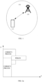
FIG. 1 is a system architecture diagram of an example communication system provided in the disclosure. -
FIG. 2a is a schematic diagram of a physical downlink data channel (PDSCH) resource provided in the disclosure. -
FIG. 2b is a schematic diagram of another PDSCH resource provided in the disclosure. -
FIG. 2c is a schematic diagram of another PDSCH resource provided in the disclosure. -
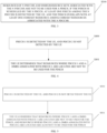
FIG. 3 is a schematic flowchart of a method for PDSCH resource determination provided in the disclosure. -
FIG. 4 is a schematic flowchart of a method for PDSCH resource determination provided inimplementation 1 of the disclosure. -
FIG. 5 is a schematic flowchart of a method for PDSCH resource determination provided inimplementation 2 of the disclosure. -
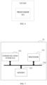
FIG. 6 is a schematic structural diagram of user equipment (UE) provided in implementations of the disclosure. -
FIG. 7 is a schematic structural diagram of a terminal provided in implementations of the disclosure. - Implementations of the disclosure are described below with reference to the drawings in implementations of the disclosure.
- The term "and/or" herein describes only an association relationship for describing associated objects and represents that three relationships may exist. For example, A and/or B may represent the following three cases: only A exists, both A and B exist, and only B exists. In addition, the character "/" herein indicates an "or" relationship between the associated objects.
- The "multiple" in implementations of the disclosure refers to two or more. The descriptions of "first", "second", and the like in implementations of the disclosure are merely for illustration and to distinguish and describe objects rather than limit the order or the number of devices in implementations of the disclosure, and do not constitute any limitation to implementations of the disclosure. The "connection" in implementations of the disclosure refers to various connections such as direct connection or indirect connection to realize communication between devices, which is not limited herein.
- The technical solution of implementations of the disclosure may be applied to an
example communication system 100 illustrated inFIG. 1 . Theexample communication system 100 includes aterminal 110 and anetwork device 120. Theterminal 110 is in communication connection with thenetwork device 120. - The
example communication system 100 may be, for example, a global system of mobile communication (GSM), a code division multiple access (CDMA) system, a wideband code division multiple access (WCDMA) system, a general packet radio service (GPRS) system, a long term evolution (LTE) system, an advanced LTE (LTE-A) system, a new radio (NR) system, an evolved system of the NR system, an LTE-based access to unlicensed spectrum (LTE-U) system, an NR-based access to unlicensed spectrum (NR-U) system, a universal mobile telecommunication system (UMTS), a next-generation communication system, or other communication systems, etc. - Generally speaking, a conventional communication system generally supports a limited number of connections and therefore is easy to implement. However, with development of communication technology, a mobile communication system will not only support conventional communication but also support, for example, device to device (D2D) communication, machine to machine (M2M) communication, machine type communication (MTC), and vehicle to vehicle (V2V) communication. Implementations of the disclosure are also applicable to these communication systems. Optionally, a communication system in implementations of the disclosure may be applied to a carrier aggregation (CA) scenario, a dual connectivity (DC) scenario, or a standalone (SA) network deployment scenario.
- The terminal 110 in implementations of the disclosure may be referred to as user equipment (UE), an access terminal, a subscriber unit, a subscriber station, a mobile station, a remote station, a remote terminal, a mobile device, a user terminal, a terminal, a wireless communication device, a user agent, or a user device. The terminal may also be a cellular phone, a cordless phone, a session initiation protocol (SIP) phone, a wireless local loop (WLL) station, a personal digital assistant (PDA), a handheld device with wireless communication functions, a computing device, other processing devices coupled with a wireless modem, a relay device, an in-vehicle device, a wearable device, a terminal in a future 5th-generation (5G) network, a terminal in a future evolved public land mobile network (PLMN), etc., which is not limited herein.
- The
network device 120 in implementations of the disclosure may be a device that communicates with the terminal. The network device may be an evolved NodeB (eNB or eNodeB) in the LTE system, or a radio controller in a cloud radio access network (CRAN). Alternatively, the network device may be a relay device, an access point, an in-vehicle device, a wearable device, a network device in the future 5G network or a network device in the future evolved PLMN, an antenna panel or a group of antenna panels (including multiple antenna panels) of a base station in the 5G system, or may be a network node forming a gNB or a transmission point, such as a baseband unit (BBU) or a distributed unit (DU), which is not limited herein. - In some deployments, the gNB may include a centralized unit (CU) and a DU. The gNB may further include an active antenna unit (AAU). The CU implements some functions of the gNB, and the DU implements some other functions of the gNB. For example, the CU is responsible for processing non-real-time protocols and services, and implements functions of a radio resource control (RRC) layer and functions of a packet data convergence protocol (PDCP) layer. The DU is responsible for processing physical (PYH) layer protocols and real-time services, and implements functions of a radio link control (RLC) layer, functions of a media access control (MAC) layer, and functions of a PHY layer.
- In the PDCCH enhancement between the terminal and the network device in the communication system as illustrated in
FIG. 1 , PDCCH repeated scheduling in the frequency domain is a possible candidate solution. As illustrated inFIG. 2a , a possible PDCCH repeated scheduling is illustrated inFIG. 2a . Referring toFIG. 2a , a resource wherePDCCH 1 is located and a resource wherePDCCH 2 is located belong to different control resource set (CORESET) resources. That is, the resource wherePDCCH 1 is located belongs to CORESET 1 and the resource wherePDCCH 2 is located belongs toCORESET 2.PDCCH 1 andPDCCH 2 are repetitions of a PDCCH. That is, at least downlink control information (DCI) carried byPDCCH 1 and a DCI carried byPDCCH 2 schedule a same PDSCH resource. As illustrated inFIG. 2a , the PDSCH overlaps with a CORESET resource wherePDCCH 1 is located. - Therefore, in an optional solution, if merely PDCCH 1 is detected by the UE and
PDCCH 2 is not detected by the UE, the UE may consider that resources wherePDCCH 1 and a demodulation reference signal (DMRS) associated withPDCCH 1 are located are not to be used for the PDSCH, i.e., as illustrated inFIG. 2b . - Therefore, in another optional solution, if merely PDCCH 2 is detected by the UE and
PDCCH 1 is not detected by the UE, the UE may consider that a resource as illustrated inFIG. 2a is to be used for the PDSCH. - As can be seen from the above, different PDCCH states resolved by the UE may lead to different cognition of the UE, i.e., different resources occupied by the PDSCH, which may result in the inconsistency of understanding between the gNB and the UE, thus reducing the network performance.
- Referring to
FIG. 3, FIG. 3 provides a method for PDSCH resource determination. The method illustrated inFIG. 3 can be performed by the terminal in the communication system as illustrated inFIG. 1 . The terminal can specifically be a UE, and the UE may specifically include a device with communication functions such as a smart phone, a tablet computer, a PDA, a smart watch, etc. The communication may support multiple protocols, the specific communication protocol supported by the UE is not limited herein. The method is as illustrated inFIG. 3 and includes the following steps. - Step S300, resources of n PDCCHs and DMRS resource sets associated with the n PDCCHs are not to be used for a PDSCH, if the PDSCH is scheduled by the n PDCCH, at least one PDCCH among the n PDCCHs is detected by the UE, and the PDSCH overlaps with at least one CORESET resource among CORESET resource(s) associated with the n PDCCHs.
- n may be an integer greater than or equal to 2. Specifically, n may be 2, 3, 4, etc.
- The at least one PDCCH among the n PDCCHs being detected by the UE may specifically include: one PDCCH among the n PDCCHs being detected by the UE, and remaining PDCCHs among the n PDCCHs being not detected by the UE, or m PDCCHs among the n PDCCHs being detected by the UE, and remaining n-m PDCCHs among the n PDCCHs being not detected by the UE, where n is greater than or equal to 2, and m is greater than or equal to 1 and less than n, or all PDCCHs among the n PDCCHs being detected by the UE.
- The CORESET resources associated with the n PDCCHs may specifically include the following. Each of the n PDCCHs is associated with a CORESET resource, and the CORESET resources may be n CORESET resources. That is, one PDCCH is associated with one CORESET resource. In practical applications, multiple PDCCHs among the n PDCCHs may be associated with the same CORESET resource. For example, two PDCCHs may be associated with one CORESET resource. Alternatively, the n PDCCHs may be associated with one CORESET resource. A specific form of the CORESET resources is not limited herein.
- In the technical solution provided in the disclosure, when the PDSCH is scheduled by the n PDCCHs, the UE can detect at least one PDCCH among the n pieces of PDCCH scheduling, and the PDSCH overlaps with at least one CORESET resource among the CORESET resources associated with the n PDCCHs, then the resources of the n PDCCHs and the DMRS resource sets associated with the n PDCCHs are not to be used for the PDSCH. That is, a resource as illustrated in
FIG. 2b is to be used for the PDSCH. In the technical solution of the disclosure, the resources of the n PDCCHs and the DMRS resource sets associated with the n PDCCHs are not to be used regardless of which PDCCH or PDCCHs among the n pieces of PDCCH scheduling is detected. Therefore, the resource to be used for the PDSCH is uniquely determined. That is, the resource as illustrated inFIG. 2b is to be adopted. In this way, the cognition inconsistency between the UE and the base station device can be avoided, and the network performance can be improved. - In an optional solution, the PDSCH overlapping with the at least one CORESET resource among the CORESET resources associated with the n PDCCHs may specifically include: the PDSCH overlapping with one CORESET resource in CORESETs associated with the n PDCCHs, and the PDSCH not overlapping with remaining CORESET resources in the CORESETs associated with the n PDCCHs, or the PDSCH overlapping with the CORESET resources associated with the n PDCCHs, that is, if multiple CORESET resources are associated with the n PDCCHs, the PDSCH overlaps with the multiple CORESET resources.
-
Implementation 1 of the disclosure provides a method for resource determination. The method can be performed by the terminal in the communication system as illustrated inFIG. 1 . The technical scenario for implementing implementations of the disclosure is as follows. In this implementation, the n PDCCHs are two PDCCHs, which are referred to asPDCCH 1 andPDCCH 2 herein for the convenience of description. The resource wherePDCCH 1 is located and the resource wherePDCCH 2 is located belong to different CORESET resources, andPDCCH 1 andPDCCH 2 are repetitions of a PDCCH. That is, at least a DCI carried byPDCCH 1 and a DCI carried byPDCCH 2 schedule a same PDSCH resource. The PDSCH overlaps with a CORESET resource wherePDCCH 1 is located, and does not overlap with a CORSET resource wherePDCCH 2 is located. The method is as illustrated inFIG. 4 and includes the following steps. - Step S400,
PDCCH 1 is detected by the UE, andPDCCH 2 is not detected by the UE. - Step S401, the UE determines that resources where
PDCCH 1 and a DMRS associated withPDCCH 1 are located are not to be used for the PDSCH. That is, the resource as illustrated inFIG. 2b is to be used for the PDSCH. - In an optional solution, step S400 may also be replaced by other steps, for example: step S400-1,
PDCCH 2 is detected by the UE, andPDCCH 1 is not detected by the UE, or step S400-2,PDCCH 1 andPDCCH 2 are detected by the UE. - In implementations provided in the disclosure, when the PDSCH is scheduled by two PDCCHs, the UE can detect at least one PDCCH among the two pieces of PDCCH, and the PDSCH overlaps with the CORESET resource associated with
PDCCH 1, then a DMRS resource set associated with thePDCCH 1 resource is not to be used for the PDSCH. That is, the resource as illustrated inFIG. 2b is to be used for the PDSCH. In the technical solution of the disclosure, the DMRS resource sets associated with the two PDCCH resources are not to be used regardless of which or all PDCCHs among the n pieces of PDCCH scheduling is detected. Therefore, in the technical scenario ofimplementation 1, the resource to be used for the PDSCH is uniquely determined. That is, the resource as illustrated inFIG. 2b is to be adopted. In this way, the cognition inconsistency between the UE and the base station device can be avoided, and the network performance can be improved. -
Implementation 2 of the disclosure provides a method for resource determination. The method can be performed by the terminal in the communication system as illustrated inFIG. 1 . The technical scenario for implementing implementations of the disclosure is as follows. In this implementation, the n PDCCHs are two PDCCHs, which are referred to asPDCCH 1 andPDCCH 2 herein for the convenience of description. The resource wherePDCCH 1 is located and the resource wherePDCCH 2 is located belong to different CORESET resources, andPDCCH 1 andPDCCH 2 are repetitions of a PDCCH. That is, at least a DCI carried byPDCCH 1 and a DCI carried byPDCCH 2 schedule a same PDSCH resource. The PDSCH overlaps with a CORESET resource wherePDCCH 1 is located, and overlaps with a CORSET resource wherePDCCH 2 is located, as illustrated inFIG. 2c . The method is as illustrated inFIG. 5 and includes the following steps. - Step S500,
PDCCH 1 is detected by the UE, andPDCCH 2 is not detected by the UE. - Step S501, the UE considers that resources where
PDCCH 1 and a DMRS associated withPDCCH 1 are located are not to be used for the PDSCH, and resources wherePDCCH 2 and a DMRS associated withPDCCH 2 are located are also not to be used for the PDSCH. That is, a resource as illustrated inFIG. 2b is to be used for the PDSCH. - In optional implementations, step S500 may also be replaced by step S400-1 or step S400-2.
- In implementations provided in the disclosure, when the PDSCH is scheduled by two PDCCHs, the UE can detect at least one PDCCH among the two pieces of PDCCH, and the PDSCH overlaps with the CORESET resource associated with
PDCCH 1 and the CORESET resource associated withPDCCH 2, then thePDCCH 1 resource and a DMRS resource set associated with thePDCCH 1 resource are not to be used for the PDSCH, and thePDCCH 2 resource and a DMRS resource set associated with thePDCCH 2 resource are also not to be used for the PDSCH. That is, the resource as illustrated inFIG. 2b is to be used for the PDSCH. In the technical solution of the disclosure, the two PDCCH resources and the DMRS resource sets associated with the two PDCCH resources are not to be used regardless of which or all PDCCHs among the two pieces of PDCCH scheduling is detected. Therefore, in the technical scenario ofimplementation 2, the resource to be used for the PDSCH is uniquely determined. That is, the resource as illustrated inFIG. 2b is to be adopted. In this way, the cognition inconsistency between the UE and the base station device can be avoided, and the network performance can be improved. - Implementations of the disclosure further provide an apparatus for PDSCH resource determination. The apparatus includes a processing unit. The processing unit is configured to not use resources of n PDCCHs and DMRS resource sets associated with the n PDCCHs for a PDSCH, if the PDSCH is scheduled by the n PDCCH, at least one PDCCH among the n PDCCHs is detected, and the PDSCH overlaps with at least one CORESET resource among CORESET resource(s) associated with the n PDCCHs.
- According to the apparatus for PDSCH resource determination provided in the disclosure, when the PDSCH is scheduled by the n PDCCHs, the UE can detect at least one PDCCH among the n pieces of PDCCH scheduling, and the PDSCH overlaps with at least one CORESET resource among the CORESET resources associated with the n PDCCHs, then the resources of the n PDCCHs and the DMRS resource sets associated with the n PDCCHs are not to be used for the PDSCH. That is, a resource as illustrated in
FIG. 2b is to be used for the PDSCH. In the technical solution of the disclosure, the resources of the n PDCCHs and the DMRS resource sets associated with the n PDCCHs are not to be used regardless of one or several PDCCHs among the n pieces of PDCCH scheduling is detected. Therefore, the resource to be used for the PDSCH is uniquely determined. That is, the resource as illustrated inFIG. 2b is to be adopted. In this way, the cognition inconsistency between the UE and the base station device can be avoided, and the network performance can be improved. - It can be understood that, in order to implement the above functions, the UE includes hardware and/or software modules corresponding to respective functions. In combination with the algorithm steps of examples described in implementations disclosed herein, the disclosure can be implemented in hardware or a combination of hardware and computer software. Whether a function is implemented by hardware or hardware driven by the computer software depends on the particular application and design constraints of the technical solution. Those skilled in the art may use different methods to implement the described functions for each particular application in combination with implementations, but such implementation should not be considered as beyond the scope of the disclosure.
- According to implementations, functional modules of the electronic device may be divided according to the above method examples. For example, each functional module may be divided according to each function, and two or more functions may be integrated in one processing module. The above integrated module may be implemented in the form of hardware. It should be noted that the division of modules in implementations is schematic, and is merely a logical function division, and there may be other division manners in actual implementation.
- In the case of dividing each functional module according to each function,
FIG. 6 is a schematic diagram of a UE. As illustrated inFIG. 6 , theUE 600 may include aprocessor 601. - The
processor 601 may be configured to support the UE to perform thestep 300, etc., and/or other processes for the technologies described herein. - It should be noted that all relevant content of the steps involved in the above method implementations can be cited in function descriptions of corresponding function modules, which will not be repeated herein.
- The UE provided in implementations is configured to perform the method illustrated in
FIG. 3 , so as to achieve the same effect as the above implementation methods. - In the case of using the integrated unit, the UE may include a processing module, a storage module, and a communication module. The processing module may be configured to control and manage actions of the UE, for example, may be configured to support the electronic device to perform the steps performed by the
processor 601. The memory module can be configured to support the electronic device to execute stored program codes and data, and the like. The communication module can be configured to support the communication between the electronic device and other devices. - The processing module may be a processor or a controller. The processing module can implement or execute the various illustrative logical blocks, modules, and circuits described in combination with the disclosure. The processor may also be a combination of computing functions, for example, a combination of one or more microprocessors, a combination of digital signal processing (DSP) and a microprocessor, and the like. The storage module may be a memory. Specifically, the communication module may be a device that interacts with other electronic devices, such as a radio frequency (RF) circuit, a Bluetooth chip, and a Wi-Fi chip.
- It can be understood that the interface connection relationship between modules illustrated in implementations of the disclosure is merely for schematic illustration, and does not constitute a structural limitation on the UE. In other implementations of the disclosure, the UE may also adopt different interface connection modes in the foregoing implementations, or a combination of multiple interface connection modes.
- Referring to
FIG. 7, FIG. 7 illustrates a terminal 70 provided in implementations of the disclosure. The terminal 70 includes aprocessor 701, amemory 702, and acommunication interface 703. Theprocessor 701, thememory 702, and thecommunication interface 703 are connected with one another via abus 704. - The
memory 702 includes but is not limited to a random access memory (RAM), a read-only memory (ROM), a erasable programmable ROM (EPROM), or a compact disc ROM (CD-ROM). Thememory 702 is configured for related computer programs and data. Thecommunication interface 703 is configured to receive and transmit data. - The
processor 701 may be one or more central processing units (CPU). In a case where theprocessor 701 is a CPU, the CPU may be a single-core CPU or a multi-core CPU. - The
processor 701 may include one or more processing units. For example, the processing unit may include an application processor (AP), a modem processor, a graphics processing unit (GPU), an image signal processor (ISP), a controller, a video codec, a digital signal processor (DSP), a baseband processor, and/or a neural-network processing unit (NPU), etc. Different processing units may be independent components, or may be integrated in one or more processors. In some implementations, the UE may also include one or more processing units. The controller can generate an operation control signal according to the instruction operation code and the timing signal, and complete the control of fetching and executing the instruction. In some other implementations, a memory may also be set in the processing unit for storing instructions and data. Exemplarily, the memory in the processing unit may be a cache memory. The memory can hold instructions or data that have just been used or recycled by the processing unit. If the processing unit needs to use the instruction or data again, the instruction or data can be invoked directly from the memory. In this way, repeated access is avoided, and the waiting time of the processing unit is reduced, thereby improving the efficiency of the UE in processing data or executing instructions. - In some implementations, the
processor 701 may include one or more interfaces. The interface may include an inter-integrated circuit (I2C) interface, an inter-integrated circuit sound (I2S) interface, a pulse code modulation (PCM) interface, a universal asynchronous receiver/transmitter (UART) interface, a mobile industry processor interface (MIPI), a general-purpose input/output (GPIO) interface, a SIM card interface, and/or a USB interface, etc. The USB interface is an interface conforming to the USB standard specification. Specifically, the USB interface may be a mini USB interface, a micro USB interface, a USB type C interface, and the like. The USB interface can be configured to connect a charger to charge the UE, and can also be configured to transmit data between the UE and peripheral equipment. The USB interface can also be configured to connect a headset and play audio through the headset. - The
processor 701 in the terminal 70 is configured to read computer program codes stored in thememory 702 to perform the following operations. Resources of n PDCCHs and DMRS resource sets associated with the n PDCCHs are not to be used for a PDSCH, if the PDSCH is scheduled by the n PDCCH, at least one PDCCH among the n PDCCHs is detected by the UE, and the PDSCH overlaps with at least one CORESET resource among CORESET resource(s) associated with the n PDCCHs, where n is an integer greater than or equal to 2. - All relevant content of the scenarios involved in the above method implementations can be cited in function descriptions of corresponding function modules, which will not be repeated herein.
- Implementations of the disclosure further provide a chip system. The chip system includes at least one processor, a memory, and an interface circuit. The memory, the transceiver, and the at least one processor are interconnected through lines. The at least one memory is configured to store computer programs. The computer programs are operable with the processor to perform the method flows illustrated in
FIGs. 3, 4, and 5 . - Implementations of the disclosure further provide a computer-readable storage medium. The computer-readable storage medium stores computer programs. When running on a network device, the computer programs are configured to perform the method flows illustrated in
FIGs. 3, 4, and 5 . - Implementations of the disclosure further provide a computer program product. When running on a terminal, the computer program product is configured to perform the method flows illustrated in
FIGs. 3, 4, and 5 . - Implementations of the disclosure further provide a terminal. The terminal includes a processor, a memory, and a communication interface. The memory is configured to store one or more programs. The one or more programs are configured to be executed by the processor. The programs include instructions for performing the method of implementations illustrated in
FIGs. 3, 4, and 5 . - The foregoing solution of the implementations of the disclosure is mainly described from the viewpoint of execution process of the method. It can be understood that, in order to implement the above functions, the electronic device includes hardware structures and/or software modules corresponding to the respective functions. Those skilled in the art should readily recognize that, in combination with the example units and scheme steps described in the implementations provided herein, the present disclosure can be implemented in hardware or a combination of the hardware and computer software. Whether a function is implemented by way of the hardware or hardware driven by the computer software depends on the particular application and design constraints of the technical solution. Those skilled in the art may use different methods to implement the described functions for each particular application, but such implementation should not be considered as beyond the scope of the present disclosure.
- According to the implementations of the disclosure, functional units may be divided for the electronic device in accordance with the foregoing method examples. For example, each functional unit may be divided according to each function, and two or more functions may be integrated in one processing unit. The above-mentioned integrated unit can be implemented in the form of hardware or software functional units. It should be noted that the division of units in the implementations of the present disclosure is schematic, and is merely a logical function division, and there may be other division manners in actual implementation.
- It should be noted that, for the sake of simplicity, the foregoing method implementations are described as a series of action combinations, however, it will be appreciated by those skilled in the art that the disclosure is not limited by the sequence of actions described. According to the disclosure, certain steps or operations may be performed in other order or simultaneously. Besides, it will be appreciated by those skilled in the art that the implementations described in the specification are exemplary implementations and the actions and modules involved are not necessarily essential to the disclosure.
- In the foregoing implementations, the description of each implementation has its own emphasis. For the parts not described in detail in one implementation, reference may be made to related descriptions in other implementations.
- In implementations provided in the disclosure, it should be understood that, the apparatus disclosed in implementations provided herein may be implemented in other manners. For example, the device/apparatus implementations described above are merely illustrative; for instance, the division of the unit is only a logical function division and there can be other manners of division during actual implementations, for example, multiple units or components may be combined or may be integrated into another system, or some features may be ignored, omitted, or not performed. In addition, coupling or communication connection between each illustrated or discussed component may be direct coupling or communication connection, or may be indirect coupling or communication among devices or units via some interfaces, and may be electrical connection, mechanical connection, or other forms of connection.
- The units described as separate components may or may not be physically separated, the components illustrated as units may or may not be physical units, that is, they may be in the same place or may be distributed to multiple network elements. All or part of the units may be selected according to actual needs to achieve the purpose of the technical solutions of the implementations.
- In addition, the functional units in various implementations of the disclosure may be integrated into one processing unit, or each unit may be physically present, or two or more units may be integrated into one unit. The above-mentioned integrated unit can be implemented in the form of hardware or a software function unit.
- The integrated unit may be stored in a computer-readable memory when it is implemented in the form of a software functional unit and is sold or used as a separate product. Based on such understanding, the technical solutions of the disclosure essentially, or the part of the technical solutions that contributes to the related art, or all or part of the technical solutions, may be embodied in the form of a software product which is stored in a memory and includes instructions for causing a computer device (which may be a personal computer, a server, or a network device and so on) to perform all or part of the steps described in the various implementations of the disclosure. The memory includes various medium capable of storing program codes, such as a universal serial bus (USB) flash disk, a ROM, a RAM, a removable hard disk, disk, compact disc (CD), or the like.
- It will be understood by those of ordinary skill in the art that all or a part of the various methods of the implementations described above may be accomplished by means of a program to instruct associated hardware, the program may be stored in a computer-readable memory, which may include a flash memory, a ROM, a RAM, disk or compact disc (CD), and so on.
Claims (16)
- A method for physical downlink data channel (PDSCH) resource determination, being applied to user equipment (UE) and comprising:resources of n physical downlink control channels (PDCCH) and demodulation reference signal (DMRS) resource sets associated with the n PDCCHs are not to be used for a PDSCH, if the PDSCH is scheduled by the n PDCCH, at least one PDCCH among the n PDCCHs is detected by the UE, and the PDSCH overlaps with at least one control resource set (CORESET) resource among CORESET resources associated with the n PDCCHs;n being an integer greater than or equal to 2.
- The method of claim 1, wherein the PDSCH overlapping with the at least one CORESET resource among the CORESET resources associated with the n PDCCHs specifically comprises:
the PDSCH overlapping with one CORESET resource in CORESETs associated with the n PDCCHs, and the PDSCH not overlapping with remaining CORESET resources in the CORESETs associated with the n PDCCHs. - The method of claim 2, wherein the at least one PDCCH among the n PDCCHs being detected by the UE specifically comprising:one PDCCH among the n PDCCHs being detected by the UE, and remaining PDCCHs among the n PDCCHs being not detected by the UE; orall PDCCHs among the n PDCCHs being detected by the UE.
- The method of claim 1, wherein the PDSCH overlapping with the at least one CORESET resource among the CORESET resources associated with the n PDCCHs specifically comprises:
the PDSCH overlapping with the CORESET resources associated with the n PDCCHs. - The method of claim 4, wherein the at least one PDCCH among the n PDCCHs being detected by the UE specifically comprising:one PDCCH among the n PDCCHs being detected by the UE, and remaining PDCCHs among the n PDCCHs being not detected by the UE; orall PDCCHs among the n PDCCHs being detected by the UE.
- An apparatus for physical downlink data channel (PDSCH) resource determination, comprising a processing unit configured to:
not use resources of n physical downlink control channels (PDCCH) and demodulation reference signal (DMRS) resource sets associated with the n PDCCHs for a PDSCH, if the PDSCH is scheduled by the n PDCCH, at least one PDCCH among the n PDCCHs is detected, and the PDSCH overlaps with at least one control resource set (CORESET) resource among CORESET resources associated with the n PDCCHs. - The apparatus of claim 6, wherein the PDSCH overlapping with the at least one CORESET resource among the CORESET resources associated with the n PDCCHs specifically comprises:
the PDSCH overlapping with one CORESET resource in CORESETs associated with the n PDCCHs, and the PDSCH not overlapping with remaining CORESET resources in the CORESETs associated with the n PDCCHs. - The apparatus of claim 6, whereinone PDCCH among the n PDCCHs is detected by the processing unit, and remaining PDCCHs among the n PDCCHs are not detected by the processing unit; orall PDCCHs among the n PDCCHs are detected by the processing unit.
- The apparatus of claim 6, wherein the PDSCH overlapping with the at least one CORESET resource among the CORESET resources associated with the n PDCCHs specifically comprises:
the PDSCH overlapping with the CORESET resources associated with the n PDCCHs. - The apparatus of claim 6, whereinone PDCCH among the n PDCCHs is detected by the processing unit, and remaining PDCCHs among the n PDCCHs are not detected by the processing unit; orall PDCCHs among the n PDCCHs are detected by the processing unit of the UE.
- A user equipment (UE), comprising:a communication unit; anda processor configured to:
not use resources of n physical downlink control channels (PDCCH) and demodulation reference signal (DMRS) resource sets associated with the n PDCCHs for a PDSCH, if the PDSCH is scheduled by the n PDCCH, at least one PDCCH among the n PDCCHs is detected, and the PDSCH overlaps with at least one control resource set (CORESET) resource among CORESET resources associated with the n PDCCHs. - A terminal, comprising:a processor;a memory; anda communication interface, wherein the memory is configured to store one or more programs, the one or more programs are configured to be executed by the processor, and the programs comprises instructions for performing the method of any of claims 1 to 5.
- A chip system, comprising:at least one processor;a memory; andan interface circuit, wherein the memory, the transceiver, and the at least one processor are interconnected through lines, the at least one memory is configured to store computer programs, and the computer programs are operable with the processor to perform the method of any of claims 1 to 5.
- A network device being configured to support a terminal device to perform the method of any of claims 1 to 5.
- A computer-readable storage medium storing computer programs, when running on user equipment (UE), the computer programs being configured to perform the method of any of claims 1 to 5.
- A computer program product comprising a non-transitory computer-readable storage medium storing computer programs, the computer programs being operable with a computer to perform the method of any of claims 1 to 5.
Applications Claiming Priority (2)
| Application Number | Priority Date | Filing Date | Title |
|---|---|---|---|
| CN202011054717.6A CN114337949B (en) | 2020-09-29 | 2020-09-29 | Method for determining physical downlink data channel (PDSCH) resource and related products |
| PCT/CN2021/119909 WO2022068667A1 (en) | 2020-09-29 | 2021-09-23 | Physical downlink shared channel (pdsch) resource determination method and related product |
Publications (2)
| Publication Number | Publication Date |
|---|---|
| EP4224764A1 true EP4224764A1 (en) | 2023-08-09 |
| EP4224764A4 EP4224764A4 (en) | 2024-04-17 |
Family
ID=80949557
Family Applications (1)
| Application Number | Title | Priority Date | Filing Date |
|---|---|---|---|
| EP21874328.4A Pending EP4224764A4 (en) | 2020-09-29 | 2021-09-23 | METHOD FOR DETERMINING THE RESOURCE OF A SHARED PHYSICAL DOWNLINK CHANNEL (PDSCH) AND RELATED PRODUCT |
Country Status (4)
| Country | Link |
|---|---|
| US (1) | US20230379934A1 (en) |
| EP (1) | EP4224764A4 (en) |
| CN (1) | CN114337949B (en) |
| WO (1) | WO2022068667A1 (en) |
Families Citing this family (1)
| Publication number | Priority date | Publication date | Assignee | Title |
|---|---|---|---|---|
| US20240215026A1 (en) * | 2022-12-22 | 2024-06-27 | Samsung Electronics Co., Ltd. | Scheduling restrictions for a physical downlink shared channel (pdsch) demodulation reference signal (dmrs) |
Family Cites Families (7)
| Publication number | Priority date | Publication date | Assignee | Title |
|---|---|---|---|---|
| CN111164924B (en) * | 2017-06-26 | 2022-10-18 | 苹果公司 | Reference signal collision handling |
| JP2019075609A (en) * | 2017-10-12 | 2019-05-16 | シャープ株式会社 | Terminal device, base station device, and communication method |
| CN111615802B (en) * | 2018-01-16 | 2024-08-02 | 联想(新加坡)私人有限公司 | Rate matching data transmissions around a resource |
| US11070310B2 (en) * | 2018-05-01 | 2021-07-20 | Qualcomm Incorporated | Rate-matching across downlink transmission repetitions in wireless communications |
| CN112737738A (en) * | 2018-05-21 | 2021-04-30 | 华为技术有限公司 | Method and device for transmitting uplink control information |
| US11122602B2 (en) * | 2018-07-11 | 2021-09-14 | QUALCMOM Incorporated | Shared channel rate matching with wideband demodulation reference signal for a control channel |
| CN110830156B (en) * | 2018-08-09 | 2021-11-26 | 大唐移动通信设备有限公司 | Channel transmission method, device, terminal and base station |
-
2020
- 2020-09-29 CN CN202011054717.6A patent/CN114337949B/en active Active
-
2021
- 2021-09-23 WO PCT/CN2021/119909 patent/WO2022068667A1/en not_active Ceased
- 2021-09-23 US US18/029,246 patent/US20230379934A1/en active Pending
- 2021-09-23 EP EP21874328.4A patent/EP4224764A4/en active Pending
Also Published As
| Publication number | Publication date |
|---|---|
| WO2022068667A1 (en) | 2022-04-07 |
| EP4224764A4 (en) | 2024-04-17 |
| CN114337949B (en) | 2024-11-29 |
| US20230379934A1 (en) | 2023-11-23 |
| CN114337949A (en) | 2022-04-12 |
Similar Documents
| Publication | Publication Date | Title |
|---|---|---|
| CN114342466B (en) | Terminal capability reporting method, terminal capability acquisition method and related device | |
| WO2020164576A1 (en) | Random access method and apparatus | |
| US11317453B2 (en) | Device to device communication method for reducing mutual interference between different types of terminal devices, terminal device and network device | |
| CN112311511B (en) | Data transmission method and device | |
| WO2020015715A1 (en) | Data transmission method and device | |
| EP4224764A1 (en) | Physical downlink shared channel (pdsch) resource determination method and related product | |
| WO2021068762A1 (en) | Carrier configuration method and related apparatus | |
| WO2023143011A1 (en) | Communication method and apparatus | |
| CN108809560B (en) | Pre-demodulation reference signal configuration method, network side device and terminal | |
| WO2022078321A1 (en) | Uplink information sending method and related product | |
| CN113615276B (en) | Communication method and device | |
| CN114286397A (en) | Transmission link switching method and related product | |
| US20240015574A1 (en) | Method for triggering buffer status report by relay and related products | |
| CN116602022A (en) | Wireless communication method, terminal device and network device | |
| CN114286292B (en) | Feedback method of multicast service and related products | |
| EP4608018A1 (en) | Energy-saving method and related device | |
| EP4224937A1 (en) | Service-based relay selection method and related product | |
| CN114257356A (en) | HARQ-ACK feedback method and related product | |
| CN114337961B (en) | Method for uplink channel transmission resources and related products | |
| WO2022033424A1 (en) | Resource transmission method and apparatus, and communication device | |
| CN113691947B (en) | Method, device, chip and module equipment for receiving paging message | |
| WO2025065367A1 (en) | Methods, devices, and systems for ue capability coordination | |
| CN114257345B (en) | Method and related products for confirming HARQ-ACK feedback time | |
| EP4456635A1 (en) | Beam determination method and apparatus | |
| EP4195569A1 (en) | Method for confirming control channel element (cce) index, and related product |
Legal Events
| Date | Code | Title | Description |
|---|---|---|---|
| STAA | Information on the status of an ep patent application or granted ep patent |
Free format text: STATUS: THE INTERNATIONAL PUBLICATION HAS BEEN MADE |
|
| PUAI | Public reference made under article 153(3) epc to a published international application that has entered the european phase |
Free format text: ORIGINAL CODE: 0009012 |
|
| STAA | Information on the status of an ep patent application or granted ep patent |
Free format text: STATUS: REQUEST FOR EXAMINATION WAS MADE |
|
| 17P | Request for examination filed |
Effective date: 20230428 |
|
| AK | Designated contracting states |
Kind code of ref document: A1 Designated state(s): AL AT BE BG CH CY CZ DE DK EE ES FI FR GB GR HR HU IE IS IT LI LT LU LV MC MK MT NL NO PL PT RO RS SE SI SK SM TR |
|
| DAV | Request for validation of the european patent (deleted) | ||
| DAX | Request for extension of the european patent (deleted) | ||
| A4 | Supplementary search report drawn up and despatched |
Effective date: 20240314 |
|
| RIC1 | Information provided on ipc code assigned before grant |
Ipc: H04W 72/1273 20230101ALI20240308BHEP Ipc: H04L 5/00 20060101AFI20240308BHEP |
|
| STAA | Information on the status of an ep patent application or granted ep patent |
Free format text: STATUS: EXAMINATION IS IN PROGRESS |
|
| 17Q | First examination report despatched |
Effective date: 20251201 |