EP4224745A1 - Air conditioning system, air conditioning apparatus, and method for recognizing air conditioning apparatus - Google Patents
Air conditioning system, air conditioning apparatus, and method for recognizing air conditioning apparatus Download PDFInfo
- Publication number
- EP4224745A1 EP4224745A1 EP21875614.6A EP21875614A EP4224745A1 EP 4224745 A1 EP4224745 A1 EP 4224745A1 EP 21875614 A EP21875614 A EP 21875614A EP 4224745 A1 EP4224745 A1 EP 4224745A1
- Authority
- EP
- European Patent Office
- Prior art keywords
- air
- refrigerant
- indoor
- air conditioner
- outdoor
- Prior art date
- Legal status (The legal status is an assumption and is not a legal conclusion. Google has not performed a legal analysis and makes no representation as to the accuracy of the status listed.)
- Granted
Links
Images







Classifications
-
- F—MECHANICAL ENGINEERING; LIGHTING; HEATING; WEAPONS; BLASTING
- F24—HEATING; RANGES; VENTILATING
- F24F—AIR-CONDITIONING; AIR-HUMIDIFICATION; VENTILATION; USE OF AIR CURRENTS FOR SCREENING
- F24F3/00—Air-conditioning systems in which conditioned primary air is supplied from one or more central stations to distributing units in the rooms or spaces where it may receive secondary treatment; Apparatus specially designed for such systems
- F24F3/06—Air-conditioning systems in which conditioned primary air is supplied from one or more central stations to distributing units in the rooms or spaces where it may receive secondary treatment; Apparatus specially designed for such systems characterised by the arrangements for the supply of heat-exchange fluid for the subsequent treatment of primary air in the room units
- F24F3/065—Air-conditioning systems in which conditioned primary air is supplied from one or more central stations to distributing units in the rooms or spaces where it may receive secondary treatment; Apparatus specially designed for such systems characterised by the arrangements for the supply of heat-exchange fluid for the subsequent treatment of primary air in the room units with a plurality of evaporators or condensers
-
- F—MECHANICAL ENGINEERING; LIGHTING; HEATING; WEAPONS; BLASTING
- F24—HEATING; RANGES; VENTILATING
- F24F—AIR-CONDITIONING; AIR-HUMIDIFICATION; VENTILATION; USE OF AIR CURRENTS FOR SCREENING
- F24F11/00—Control or safety arrangements
- F24F11/62—Control or safety arrangements characterised by the type of control or by internal processing, e.g. using fuzzy logic, adaptive control or estimation of values
- F24F11/63—Electronic processing
-
- F—MECHANICAL ENGINEERING; LIGHTING; HEATING; WEAPONS; BLASTING
- F24—HEATING; RANGES; VENTILATING
- F24F—AIR-CONDITIONING; AIR-HUMIDIFICATION; VENTILATION; USE OF AIR CURRENTS FOR SCREENING
- F24F11/00—Control or safety arrangements
- F24F11/50—Control or safety arrangements characterised by user interfaces or communication
- F24F11/54—Control or safety arrangements characterised by user interfaces or communication using one central controller connected to several sub-controllers
-
- G—PHYSICS
- G08—SIGNALLING
- G08C—TRANSMISSION SYSTEMS FOR MEASURED VALUES, CONTROL OR SIMILAR SIGNALS
- G08C15/00—Arrangements characterised by the use of multiplexing for the transmission of a plurality of signals over a common path
- G08C15/02—Arrangements characterised by the use of multiplexing for the transmission of a plurality of signals over a common path simultaneously, i.e. using frequency division
-
- G—PHYSICS
- G08—SIGNALLING
- G08C—TRANSMISSION SYSTEMS FOR MEASURED VALUES, CONTROL OR SIMILAR SIGNALS
- G08C15/00—Arrangements characterised by the use of multiplexing for the transmission of a plurality of signals over a common path
- G08C15/06—Arrangements characterised by the use of multiplexing for the transmission of a plurality of signals over a common path successively, i.e. using time division
-
- H—ELECTRICITY
- H04—ELECTRIC COMMUNICATION TECHNIQUE
- H04L—TRANSMISSION OF DIGITAL INFORMATION, e.g. TELEGRAPHIC COMMUNICATION
- H04L12/00—Data switching networks
- H04L12/02—Details
- H04L12/12—Arrangements for remote connection or disconnection of substations or of equipment thereof
Definitions
- the present invention relates to an air-conditioning system, an air conditioner, and a method for recognizing an air conditioner.
- air-conditioning systems which include a plurality of refrigerant systems configured by connecting a plurality of air conditioners such as outdoor units and indoor units to each other so as to circulate a refrigerant.
- addresses distinguishable from each other are allocated to the air conditioners in order to manage and control each of the air conditioners. Furthermore, the information on the refrigerant system to which each air conditioner belongs is determined in association with the address so that management and control may be executed for each refrigerant system.
- An air-conditioning system is an air-conditioning system in which a plurality of air conditioners belonging to an identical refrigerant system is connected through a communication line inside the system and the plurality of air conditioners belonging to the different refrigerant systems is connected through a communication line outside the systems and, for the plurality of air conditioners belonging to the identical refrigerant system, a recognition process is executable while a control process is executed by transmission through at least the communication line inside the system.
- the recognition process may be executable while the control process is executed by transmission through both the communication line inside the system and the communication line outside the systems.
- the recognition process for the air conditioner is executable while the control process for the air conditioner is executed.
- control process and the recognition process are executed by time-division multiplexing transmission.
- the recognition process for the air conditioner is executable while the control process for the air conditioner is executed to suppress the deterioration of the environment in the target space.
- control process and the recognition process are executed by frequency-division multiplexing transmission.
- the frequency used in the transmission for the control process is different from the frequency used in the transmission for the recognition process.
- a high frequency may be used for the control process
- a low frequency may be used for the recognition process.
- the recognition process for the air conditioner is executable while the control process for the air conditioner is executed to sufficiently suppress the deterioration of the environment in the target space.
- an air-conditioning system which is the air-conditioning system according to the first aspect or the second aspect
- a process is executed in which one of the air conditioners recognizes presence of the other air conditioner belonging to the refrigerant system identical to the refrigerant system of the one of the air conditioners by transmission through the communication line inside the system in a state where transmission through the communication line outside the systems between the air conditioners belonging to the refrigerant systems different from each other is blocked.
- the air-conditioning system it is possible to reliably prevent the air conditioners belonging to the different refrigerant systems from being erroneously recognized as belonging to the identical refrigerant system.
- control process is not executed in the refrigerant system to which the unrecognized air conditioner belongs at least during a period after the unrecognized air conditioner is confirmed during execution of the recognition process until the recognition process for the unrecognized air conditioner is completed.
- the unrecognized air conditioner may be an air conditioner that is not recognized by any of the air conditioners other than itself.
- the unrecognized air conditioner may be confirmed, for example, when a new air conditioner is additionally connected, or when a component such as a control board of an existing air conditioner is replaced.
- the control process is executable for the air conditioner in the refrigerant system to which the unrecognized air conditioner does not belong while the recognition process is executed for the refrigerant system to which the unrecognized air conditioner belongs.
- the recognition process is started when the unrecognized air conditioner transmits a start request.
- the start request is not limited and, for example, the start request may be transmitted from the unrecognized air conditioner to all the air conditioners connected through the communication line in the air-conditioning system by broadcasting.
- the recognition process is executed when the unrecognized air conditioner holds an ID of the air conditioner, other than the unrecognized air conditioner, belonging to the refrigerant system identical to the refrigerant system of the unrecognized air conditioner.
- the unrecognized air conditioner holds the ID of the air conditioner, other than it, belonging to the refrigerant system identical to that of its own so that the refrigerant system to which it belongs may be determined.
- an ID based on an identifier unique to the air conditioner is assigned to the air conditioner.
- an air-conditioning system which is the air-conditioning system according to any of the first aspect to the eighth aspect, in the control process, at least any of control processes for capability control of the air conditioner and selection control of a control mode of the air conditioner is executed.
- the capability control is not limited, and when the air conditioner is controlled based on the setting temperature, examples thereof may include control on the number of revolutions of the compressor based on the setting temperature. Furthermore, the selection control of the control mode is not limited, and examples thereof may include control for selecting a specific control mode from a plurality of types of control modes such as a cooling mode and a heating mode.
- the recognition process is executable while executing the capability control of the air conditioner or the selection control of the control mode of the air conditioner.
- An air conditioner according to a tenth aspect is an air conditioner in an air-conditioning system in which a plurality of air conditioners belonging to an identical refrigerant system is connected through a communication line inside the system and the plurality of air conditioners belonging to the different refrigerant systems is connected through a communication line outside the systems, and a recognition process is executable while a control process is executed by transmission through at least the communication line inside the system with the other air conditioner belonging to the identical refrigerant system.
- the recognition process may be executable while the control process is executed by transmission through both the communication line inside the system and the communication line outside the systems.
- the control process when the recognition process is executed in the refrigerant system other than the refrigerant system to which it belongs, the control process may be executed in the refrigerant system to which it belongs, and when the recognition process is executed in the refrigerant system to which it belongs, the control process may be unexecuted in the refrigerant system to which it belongs.
- the recognition process is executable while the control process for the air conditioner is executed.
- a method for recognizing an air conditioner is a method for recognizing an air conditioner in an air-conditioning system in which a plurality of air conditioners belonging to an identical refrigerant system is connected through a communication line inside the system and the plurality of air conditioners belonging to the different refrigerant systems is connected through a communication line outside the systems, and the method includes, for the plurality of air conditioners belonging to the identical refrigerant system, executing a recognition process while executing a control process by transmission through at least the communication line inside the system.
- the recognition process may be executed while the control process is executed by transmission through both the communication line inside the system and the communication line outside the systems.
- the recognition process for the air conditioner may be executed while the control process for the air conditioner is executed.
- An example of an air-conditioning system is described below while an example of a process in a case where an air-conditioning control process of an air conditioner and a system recognition process are executed in the air-conditioning system is described.
- FIG. 1 illustrates an electric connection relation among a plurality of air conditioners (outdoor units, indoor units).
- FIG. 2 illustrates a connection relation regarding refrigerant circulation of a plurality of air conditioners (outdoor units, indoor units).
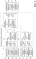
- FIG. 3 is a hardware configuration diagram of an air-conditioning system 1.
- FIG. 4 is a functional block configuration diagram of the air-conditioning system 1.
- the air-conditioning system 1 includes a plurality of refrigerant systems A, B, C, D.
- Each of the refrigerant systems A, B, C, D includes a plurality of air conditioners.
- the refrigerant system A includes an outdoor unit 10a, an indoor unit 20a, and an indoor unit 30a, through which the refrigerant circulates.
- the refrigerant system B includes an outdoor unit 10b, an indoor unit 20b, and an indoor unit 30b, through which the refrigerant circulates.
- the refrigerant system C includes an outdoor unit 10c, an indoor unit 20c, and an indoor unit 30c, through which the refrigerant circulates.
- the refrigerant system D includes an outdoor unit 10d, an indoor unit 20d, and an indoor unit 30d, through which the refrigerant circulates.
- the outdoor unit 10a, the indoor unit 20a, and the indoor unit 30a belonging to the refrigerant system A are electrically connected in a bus-type wiring form so as to enable communications through a communication line 6a inside the system, the refrigerant system A.
- the outdoor unit 10b, the indoor unit 20b, and the indoor unit 30b belonging to the refrigerant system B are electrically connected in a bus-type wiring form so as to enable communications through a communication line 6b inside the system, the refrigerant system B.
- the outdoor unit 10c, the indoor unit 20c, and the indoor unit 30c belonging to the refrigerant system C are electrically connected in a bus-type wiring form so as to enable communications through a communication line 6c inside the system, the refrigerant system C.
- the outdoor unit 10d, the indoor unit 20d, and the indoor unit 30d belonging to the refrigerant system D are electrically connected in a bus-type wiring form so as to enable communications through a communication line 6d inside the system, the refriger
- the air conditioners belonging to the refrigerant systems A, B, C, D are electrically connected so as to enable communications through a communication line 5 outside the systems.
- the outdoor unit 10a belonging to the refrigerant system A, the outdoor unit 10b belonging to the refrigerant system B, the outdoor unit 10c belonging to the refrigerant system C, and the outdoor unit 10d belonging to the refrigerant system D are connected in a bus-type wiring form through the communication line 5 outside the systems.
- each of the refrigerant systems A, B, C, D is connected to a central controller 9 through a communication line 9a.
- the central controller 9 may manage and control the air conditioners belonging to the respective refrigerant systems A, B, C, D.
- the refrigerant systems A, B, C, D include refrigerant circuits 2a, 2b, ..., which are configured by connecting refrigerant devices belonging thereto inside the respective systems.
- the respective refrigerant systems enable communications through the communication line 5 outside the systems, but the refrigerant circuits 2a, 2b, ..., in the respective refrigerant systems are physically independent from each other so that the refrigerant does not move in and out among the refrigerant systems.
- a lower-case suffix corresponding to the system name is attached to a device, or the like, belonging to each system.
- the descriptions of the devices belonging to the refrigerant systems B, C, D other than the refrigerant system A are omitted as the descriptions may be understood as the description of the device corresponding to the refrigerant system A.
- the refrigerant system A includes the outdoor unit 10a, the indoor unit 20a, the indoor unit 30a, a liquid refrigerant connection pipe 4a, a gas refrigerant connection pipe 3a, and an air-conditioning controller 8a that controls various operations in the refrigerant system A.
- the refrigerant system A performs a vapor-compression refrigeration cycle in the refrigerant system A to air-condition a target space where the indoor unit 20a is provided and a target space where the indoor unit 30a is provided.
- the outdoor unit 10a is connected to the indoor unit 20a and the indoor unit 30a through the liquid refrigerant connection pipe 4a and the gas refrigerant connection pipe 3a to form part of the refrigerant circuit 2a of the refrigerant system A.
- the outdoor unit 10a primarily includes a compressor 11a, a four-way switching valve 12a, an outdoor heat exchanger 13a, an outdoor expansion valve 16a, a low-pressure receiver 14a, an outdoor fan 15a, an outdoor controller 17a, and the like.
- the compressor 11a is a device that compresses a low-pressure refrigerant in the refrigeration cycle of the refrigerant system A to a high pressure. According to the present embodiment, the compressor 11a is used, for which the capacity is variable by controlling the operation frequency.
- the four-way switching valve 12a switches the connection state in the refrigerant circuit 2a so as to switch between the state (see the solid lines in FIG. 2 ) where a discharge side of the compressor 11a is connected to the outdoor heat exchanger 13a while a suction side of the compressor 11a is connected to the gas refrigerant connection pipe 3a through the low-pressure receiver 14a and the state (see the dotted lines in FIG. 2 ) where the discharge side of the compressor 11a is connected to the gas refrigerant connection pipe 3a while the suction side of the compressor 11a is connected to the outdoor heat exchanger 13a through the low-pressure receiver 14a.
- the outdoor heat exchanger 13a is a heat exchanger that functions as a condenser or radiator of the high-pressure refrigerant in the refrigeration cycle of the refrigerant system A during a cooling operation and functions as an evaporator of the low-pressure refrigerant in the refrigeration cycle of the refrigerant system A during a heating operation.
- the outdoor fan 15a supplies outdoor air to the outdoor heat exchanger 13a in the outdoor unit 10a and, after heat-exchanging with the refrigerant in the outdoor heat exchanger 13a, generates an air flow to be discharged to the outside of the outdoor unit 10a.
- the outdoor fan 15a is rotationally driven by an outdoor fan motor.
- the outdoor expansion valve 16a is provided between a liquid-side end portion of the outdoor heat exchanger 13a and the liquid refrigerant connection pipe 4a.
- the outdoor expansion valve 16a is, for example, an electronic expansion valve whose valve opening degree is adjustable by control.
- the low-pressure receiver 14a is a refrigerant container that is provided between the suction side of the compressor 11a and one of connection ports of the four-way switching valve 12a so as to store excess refrigerant in the refrigerant circuit 2a as liquid refrigerant.
- the outdoor controller 17a controls the operation of each unit included in the outdoor unit 10a.
- the outdoor controller 17a includes a processor 171a, a RAM 172a, a ROM 173a, a network interface 174a, and the like.
- the processor 171a includes, for example, any one or more of a CPU (Central Processing Unit), an MPU (Micro Processing Unit), a GPU (Graphics Processing Unit), a DSP (Digital Signal Processor), an ASIC (Application Specific Integrated Circuit), a PLD (Programmable Logic Device), and an FPGA (Field Programmable Gate Array).
- the RAM 172a is a Random Access Memory and functions as a primary storage memory or a working memory.
- the ROM 173a is a Read Only Memory and stores programs to be read and executed by the processor 171a in order to perform various kinds of control and processing, data for the programs, etc.
- the network interface 174a is an interface that communicably connects the outdoor controller 17a with other devices. Specifically, the network interface 174a enables communications between the outdoor controller 17a and an indoor controller 25a and an indoor controller 35a through the communication line 6a inside the system. Further, the network interface 174a enables communications between the outdoor controller 17a and the outdoor controllers belonging to the other refrigerant systems B, C, D through the communication line 5 outside the systems. Further, the network interface 174a enables communications between the outdoor controller 17a and the above-described central controller 9 through the communication line 9a.
- the network interface 174a includes a high-pass filter (HPS) 176a for communications through the communication line 5. Therefore, the communication between the outdoor controller 17a and the device outside the system through the communication line 5 may be performed, not with predetermined low-frequency signals, but only with predetermined high-frequency signals. Specifically, for example, the outdoor controller 17a of the refrigerant system A and an outdoor controller 17b of the refrigerant system B perform communications using high-frequency signals between the network interface 174a and a network interface 174b through the high-pass filter 176a, the communication line 5 outside the systems, and a high-pass filter 176b.
- HPS high-pass filter
- the outdoor controller 17a may communicate with the indoor controllers 25a, 35a inside the identical refrigerant system by using high-frequency and/or low-frequency signals, and the outdoor controller 17a may communicate with the central controller 9 by using high-frequency and/or low-frequency signals.
- various sensors which are not illustrated, are provided for the outdoor unit 10a and are connected so that the outdoor controller 17a may obtain detection values.
- the indoor unit 20a and the indoor unit 30a are installed on a wall surface, a ceiling, or the like, in a room that is an identical or different target space.
- the indoor unit 20a and the indoor unit 30a are connected in parallel to the outdoor unit 10a through the liquid refrigerant connection pipe 4a and the gas refrigerant connection pipe 3a to form part of the refrigerant circuit 2a of the refrigerant system A.
- the indoor unit 20a includes an indoor heat exchanger 21a, an indoor fan 22a, an indoor expansion valve 26a, an indoor temperature sensor 23a, a remote controller 24a, and the indoor controller 25a.
- a liquid side of the indoor heat exchanger 21a is connected to the liquid refrigerant connection pipe 4a, and a gas side end is connected to the gas refrigerant connection pipe 3a.
- the indoor heat exchanger 21a is a heat exchanger that functions as an evaporator of the low-pressure refrigerant in the refrigeration cycle during a cooling operation and functions as a condenser or radiator of the high-pressure refrigerant in the refrigeration cycle during a heating operation.
- the indoor fan 22a takes in the indoor air in the air-conditioning target space into the indoor unit 20a and, after heat-exchanging with the refrigerant in the indoor heat exchanger 21a, generates an air flow to be discharged to the outside of the indoor unit 20a.
- the indoor fan 22a is rotationally driven by an indoor fan motor.
- the indoor expansion valve 26a is provided between a liquid-side end portion of the indoor heat exchanger 21a and the liquid refrigerant connection pipe 4a.
- the indoor expansion valve 26a is, for example, an electronic expansion valve whose valve opening degree is adjustable by control.
- the indoor temperature sensor 23a detects the temperature of the space targeted by the indoor unit 20a and transmits it to the indoor controller 25a.
- the remote controller 24a is operated by a user, or the like, to receive, for example, a setting temperature and selection of an operating mode such as cooling operation or heating operation and transmits it to the indoor controller 25a.
- the indoor controller 25a includes a processor 251a, a RAM 252a, a ROM 253a, a network interface 254a, and the like.
- the processor 251a includes, for example, any one or more of a CPU, MPU, GPU, DSP, ASIC, PLD, and FPGA.
- the RAM 252a is a Random Access Memory and functions as a primary storage memory or a working memory.
- the ROM 253a is a Read Only Memory and stores programs to be read and executed by the processor 251a in order to perform various types of control and processing, data for the programs, etc.
- the network interface 254a is an interface that communicably connects the indoor controller 25a with other devices.
- the network interface 254a enables communications between the indoor controller 25a and the indoor controller 35a through the communication line 6a inside the system. Further, the network interface 254a enables communications between the indoor controller 25a and the outdoor controller 17a through the communication line 6a inside the system.
- the indoor unit 30a includes an indoor heat exchanger 31a, an indoor fan 32a, an indoor expansion valve 36a, an indoor temperature sensor 33a, a remote controller 34a, and the indoor controller 35a.
- the indoor controller 35a includes a processor 351a, a RAM 352a, a ROM 353a, a network interface 354a, and the like. These devices included in the indoor unit 30a correspond to the devices included in the indoor unit 20a described above, and the descriptions will be omitted.
- the outdoor controller 17a, the indoor controller 25a, and the indoor controller 35a are communicably connected to each other through the communication line 6a inside the system to form the air-conditioning controller 8a of the refrigerant system A.
- the air-conditioning controller 8a executes an air-conditioning control process for each device in order to satisfy a setting temperature in the refrigerant system A.
- the outdoor controller 17a, the indoor controller 25a, and the indoor controller 35a have the hardware configuration illustrated in FIG. 3 so as to have the functional block configuration illustrated in FIG. 4 .
- the outdoor controller 17a includes an outdoor air-conditioning control unit 177a and an outdoor communication unit 178a.
- the outdoor air-conditioning control unit 177a performs control to operate each device belonging to the refrigerant system A in accordance with the information on the setting temperature or the information on the operating mode from the remote controllers 24a, 34a in the identical refrigerant system or in accordance with an instruction from the central controller 9. Specifically, the outdoor air-conditioning control unit 177a performs various types of control such as start and stop of the compressor 11a, control of the operation frequency, switching control of the four-way switching valve 12a, air volume control of the outdoor fan 15a, and valve opening degree control of the outdoor expansion valve 16a.
- the outdoor communication unit 178a performs the communication between the outdoor controller 17a and the central controller 9, the communication between the outdoor controller 17a and the indoor controller 25a or the indoor controller 35a in the identical refrigerant system, and the communication between the outdoor controller 17a and the outdoor controllers 17b, 17c, 17d included in the outdoor units 10b, 10c, 10d belonging to the other refrigerant systems B, C, D.
- the outdoor communication unit 178a includes a self-ID storage unit 1781a, a system configuration storage unit 1782a, and an outdoor recognition processing unit 1783a.
- the self-ID storage unit 1781a stores the IDs that are identification numbers unique to the respective air conditioners and, specifically, stores the ID of the outdoor unit 10a of the refrigerant system A.
- the IDs of the respective air conditioners are defined corresponding to or based on the serial numbers unique to the respective air conditioners, and do not overlap each other.
- the system configuration storage unit 1782a stores the data in which the IDs of all the air conditioners belonging to the refrigerant system (here, the refrigerant system A), to which it (here, the outdoor unit 10a) belongs, are associated with each other.
- the system configuration storage unit 1782a stores the ID of the outdoor unit 10a, the ID of the indoor unit 20a, and the ID of the indoor units 30a in association with each other so that it may be understood that the air conditioners belong to the identical refrigerant system.
- the outdoor recognition processing unit 1783a executes various processes to recognize, in the air-conditioning system 1, the refrigerant system to which the air conditioner including the board belongs. Further, the outdoor recognition processing unit 1783a transmits signals based on the reference clock and performs a transmission interruption process or retransmission process in accordance with error detection from the reception side.
- the indoor controller 25a includes an indoor air-conditioning control unit 257a and an indoor communication unit 258a.
- the indoor air-conditioning control unit 257a performs control to operate each device belonging to the refrigerant system A in accordance with the information on the setting temperature or the information on the operating mode from the remote controllers 24a, 34a in the identical refrigerant system or in accordance with an instruction from the central controller 9. Specifically, the indoor air-conditioning control unit 257a performs various types of control such as obtaining detection values of the indoor temperature sensor 23a, valve opening degree control of the indoor expansion valve 26a, and air volume control of the indoor fan 22a.
- the indoor communication unit 258a performs the communication between the indoor controller 25a and the outdoor controller 17a and the communication between the indoor controller 25a and the indoor controller 35a in the identical refrigerant system.
- the indoor communication unit 258a includes a self-ID storage unit 2581a, an outdoor-unit ID storage unit 2582a, and an indoor recognition processing unit 2583a.
- the self-ID storage unit 2581a stores the IDs that are identification numbers unique to the respective air conditioners and, specifically, stores the ID of the indoor unit 20a of the refrigerant system A.
- the outdoor-unit ID storage unit 2582a stores the ID of the outdoor unit (here, the outdoor unit 10a) belonging to the refrigerant system (here, the refrigerant system A) to which it (here, the indoor unit 20a) belongs.
- the indoor recognition processing unit 2583a executes various processes to recognize, in the air-conditioning system 1, the refrigerant system to which the air conditioner including the board belongs. Further, the indoor recognition processing unit 2583a transmits signals based on the reference clock and performs a transmission interruption process or retransmission process in accordance with error detection from the reception side.
- the indoor controller 35a includes an indoor air-conditioning control unit 357a and an indoor communication unit 358a.
- the indoor communication unit 358a includes a self-ID storage unit 3581a, an outdoor-unit ID storage unit 3582a, and an indoor recognition processing unit 3583a. These configurations are the same as those described for the indoor controller 25a, and therefore the description thereof will be omitted.
- refrigerant system A has been described above as an example, the same applies to the other refrigerant systems, the refrigerant systems B, C, D.
- the refrigeration cycles of the refrigerant systems A, B, C, D in the air-conditioning system 1 are independent of each other, and the air-conditioning control process may be executed individually.
- refrigeration cycles of the refrigerant systems A, B, C, D are independent of each other, for example, when the outdoor units 10a, 10b, 10c, 10d of the respective refrigerant systems A, B, C, D receive instructions for operation start, operation stop, or the like, from the central controller 9, the control of the operation start or the control of operation stop is performed in each of the refrigerant systems A, B, C, D.
- cooling operating mode and the heating operating mode performed in the refrigerant system A will be described below as an example, the same applies to the other refrigerant systems B, C, D.
- the air-conditioning controller 8a including the outdoor controller 17a, the indoor controller 25a, and the indoor controller 35a selectively performs the cooling operating mode or the heating operating mode based on the instruction received by the remote controllers 24a, 34a, the central controller 9, or the like.
- the operation frequency of the compressor 11a is controlled for the capacity so that the evaporation temperature of the refrigerant in the refrigerant circuit 2a becomes a target evaporation temperature.
- the gas refrigerant discharged from the compressor 11a is condensed in the outdoor heat exchanger 13a through the four-way switching valve 12a.
- the refrigerant flowing through the outdoor heat exchanger 13a is decompressed when passing through the outdoor expansion valve 16a whose valve opening degree is controlled.
- the refrigerant decompressed by the outdoor expansion valve 16a flows through the liquid refrigerant connection pipe 4a and is separated and sent to the indoor unit 20a and the indoor unit 30a.
- each of the refrigerants is decompressed in the indoor expansion valve 26a whose valve opening degree is controlled, and evaporated in the indoor heat exchanger 21a, or decompressed in the indoor expansion valve 36a whose valve opening degree is controlled, and evaporated in the indoor heat exchanger 31a, is merged together, and then flow into the gas refrigerant connection pipe 3a.
- the refrigerant flowing through the gas refrigerant connection pipe 3a passes through the four-way switching valve 12a and the low-pressure receiver 14a and is again suctioned into the compressor 11a.
- the operation frequency of the compressor 11a is controlled for the capacity so that, for example, the condensation temperature of the refrigerant in the refrigerant circuit 2a becomes a target condensation temperature.
- the gas refrigerant discharged from the compressor 11a flows through the four-way switching valve 12a and the gas refrigerant connection pipe 3a and is then separated and sent to the indoor unit 20a and the indoor unit 30a.
- each of the refrigerants is condensed in the indoor heat exchanger 21a and decompressed in the indoor expansion valve 26a whose valve opening degree is controlled, or condensed in the indoor heat exchanger 31a and decompressed in the indoor expansion valve 36a whose valve opening degree is controlled, is merged together, and then flows to the liquid refrigerant connection pipe 4a.
- the refrigerant sent to the outdoor unit 10a through the liquid refrigerant connection pipe 4a is decompressed in the outdoor expansion valve 16a and evaporated in the outdoor heat exchanger 13a.
- the refrigerant evaporated in the outdoor heat exchanger 13a passes through the four-way switching valve 12a and the low-pressure receiver 14a, and is again suctioned into the compressor 11a.
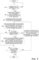
- FIG. 5 illustrates a flowchart of the system recognition process.
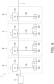
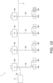
- FIGS. 6 to 12 are explanatory diagrams illustrating the states in the respective stages of the system recognition process.
- the underlined numbers in the outdoor units 10a, 10b, 10c, 10d and the indoor units 20a, 20b, 20c, 20d, 30a, 30b, 30c, 30d indicate the IDs of the air conditioners.
- the new indoor unit 30d is additionally provided in the air-conditioning system 1 where only the indoor unit 20d is connected to the outdoor unit 10d of the refrigerant system D.
- the system recognition process here will be described from a state where the indoor unit 30d is additionally connected in parallel to the indoor unit 20d in the refrigerant circuit of the refrigerant system D and is physically connected with the communication line 6d inside the system. Further, it is assumed that the air-conditioning control process is being executed for each of the air conditioners (the outdoor units 10a, 10b, 10c, 10d, the indoor units 20a, 20b, 20c, 20d, 30a, 30b, 30c) of the air-conditioning system 1.
- Step S10 the indoor unit 30d, which is newly electrically connected to the air-conditioning system 1, determines whether an electric connection has been established in the air-conditioning system 1. Specifically, an indoor recognition processing unit 3583d of an indoor communication unit 358d included in an indoor controller 35d of the indoor unit 30d determines whether a connection has been established with the communication line 6d inside the system. Here, when it is determined that the connection has been established, the process proceeds to Step S20.
- Step S20 the indoor unit 30d, which is newly electrically connected to the air-conditioning system 1, transmits a signal for a system recognition start request to all of the air conditioners (the outdoor units 10a, 10b, 10c, 10d, the indoor units 20a, 20b, 20c, 20d, 30a, 30b, 30c) electrically connected in the air-conditioning system 1 other than itself.
- the transmission of the signal for the system recognition start request here is not limited, but is performed by for example a broadcast method as illustrated in FIG. 7 .
- the outdoor units 10a, 10b, 10c, 10d include the high-pass filter 176a, and the like, signals are transmitted using a predetermined low frequency.
- the indoor recognition processing unit 3583d of the indoor communication unit 358d included in the indoor controller 35d of the indoor unit 30d transmits the signal for the system recognition start request with the connection to the communication line 6d inside the system as a trigger. Then, each of the outdoor units 10a, 10b, 10c, 10d receives the signal for the system recognition start request. Furthermore, in the stage where the signal for the system recognition start request is transmitted, the air-conditioning control process for all the refrigerant systems A, B, C, D except for the indoor unit 30d is being continued by using a time-division multiplexing communication method in the communications through the communication lines 5, 6a, 6b, 6c, 6d.
- the air-conditioning control process includes capability control such as control for achieving a target evaporation temperature or a target condensation temperature or control for achieving a setting temperature, process for mode selection control of a cooling operating mode or a heating operating mode, and the like (the same applies hereinafter).
- Step S30 by mutually transmitting a predetermined high-frequency signal among the outdoor recognition processing units 1783a, 1783b, 1783c, 1783d of all the outdoor units 10a, 10b, 10c, 10d that have received the signal for the system recognition start request, one outdoor unit that serves the role of recognizer is determined based on a predetermined rule.
- the rule of determination here is not limited, and for example the outdoor units 10a, 10b, 10c, 10d may serve the role of recognizer in numerical order, or the like, of the IDs of their own.
- the time-division multiplexing communication method is used for the communication through the communication line 5 outside the systems, and the air-conditioning control process for all the refrigerant systems A, B, C, D except for the indoor unit 30d is being continued.
- Step S40 the outdoor unit, which is determined as the role of recognizer in Step S30, executes a process to confirm the indoor units belonging to the refrigerant system to which it belongs.
- the outdoor recognition processing unit 1783a of the outdoor unit 10a first transmits a predetermined low-frequency signal as a prior signal for system recognition to the indoor units 20a, 30a through the communication line 6a inside the system, the refrigerant system A.
- the outdoor units 10a, 10b, 10c, 10d include the high-pass filters 176a, 176b, 176c, 176d, the low-frequency signal is blocked so as not to flow to the communication line 5 outside the systems.
- the outdoor recognition processing unit 1783a of the outdoor unit 10a further transmits a predetermined high-frequency signal to not only the air conditioners belonging to the refrigerant system A of its own but also all the air conditioners through the communication lines 5, 6a to d.
- the outdoor recognition processing unit 1783a includes, in the high-frequency signal, a system recognition inquiry that is an inquiry as to whether the previously transmitted prior signal has been received.
- the high-frequency signal including the system recognition inquiry further includes the information indicating the identification number "11" that is the ID of the outdoor unit 10a itself and is stored in the self-ID storage unit 1781a.
- the indoor recognition processing units 2583a, 3583a of the indoor units 20a, 30a which have received both the prior signal and the system recognition inquiry, store the information indicating the identification number "11", which is the ID of the outdoor unit 10a, in the outdoor-unit ID storage units 2582a, 3582a, respectively, or overwrite the information when the information has already been stored.
- the indoor recognition processing units 2583a, 3583a of the indoor units 20a, 30a which have received both the prior signal and the system recognition inquiry, transmit a participation request signal, which is a response indicating that the system recognition inquiry has been received, as a predetermined high-frequency signal.
- the indoor recognition processing unit 2583a of the indoor unit 20a includes, in the participation request signal, the information indicating the identification number "1" that is the ID of the indoor unit 20a itself and is stored in the self-ID storage unit 2581a.
- the indoor recognition processing unit 3583a of the indoor unit 30a includes, in the participation request signal, the information indicating the identification number "7" that is the ID of the indoor unit 30a itself and is stored in the self-ID storage unit 3581a.
- the outdoor recognition processing unit 1783a of the outdoor unit 10a which has received the participation request signal from each of the indoor units 20a, 30a, stores the IDs of the indoor units 20a, 30a included in the participation request signals in the system configuration storage unit 1782a of its own or overwrites the information when the information has already been stored. Then, as illustrated in FIG. 11 , the outdoor recognition processing unit 1783a of the outdoor unit 10a, which has received the participation request signal, transmits a participation permission signal as a predetermined high-frequency signal to each of the indoor units 20a, 30a.
- the outdoor unit 10a, the indoor unit 20a, and the indoor unit 30a belonging to the refrigerant system A may recognize that they belong to the identical refrigerant system with each other, and the system recognition process for the refrigerant system A ends.
- the time-division multiplexing communication method is used for the communication through the communication line 6a inside the system, that is, the transmission is performed while switching the use timing of the transmission path for time-sharing, so that the air-conditioning control process for the refrigerant system A is continued. Furthermore, for the other refrigerant systems B, C, D, the time-division multiplexing communication method is used for the communications through the communication lines 5, 6b to d so that the air-conditioning control process is similarly continued except for the indoor unit 30d.
- Step S50 it is determined whether there is an unrecognized indoor unit in the system recognition process in Step S40.
- the process proceeds to Step S70.
- the process proceeds to Step S70.
- Step S60 for the refrigerant system for which the presence of an unrecognized indoor unit has been confirmed, the outdoor air-conditioning control unit and the indoor air-conditioning control unit stop the air-conditioning control process, and the outdoor recognition processing unit and the indoor recognition processing unit execute the system recognition process for the unrecognized indoor unit.
- Step S70 the outdoor recognition processing units 1783a, 1783b, 1783c, 1783d of the outdoor units 10a, 10b, 10c, 10d communicate with each other to determine whether the system recognition process for all the refrigerant systems has been finished.
- the system recognition process ends.
- the process proceeds to Step S80.
- Step S80 the outdoor unit as the role of recognizer is changed to the outdoor unit belonging to the different refrigerant system, and the process proceeds to Step S40.
- the system recognition process for the refrigerant system B using the outdoor unit 10b of the refrigerant system B as the role of recognizer is executed subsequent to the system recognition by the outdoor unit 10a of the refrigerant system A as described above.
- the system recognition process for the refrigerant system C using the outdoor unit 10c of the refrigerant system C as the role of recognizer is subsequently executed, and further, the system recognition process for the refrigerant system D using the outdoor unit 10d of the refrigerant system D as the role of recognizer is executed.
- the indoor recognition processing unit 3583d of the indoor unit 30d which has received both the prior signal and the system recognition inquiry from the outdoor recognition processing unit 1783d of the outdoor unit 10d, includes, in the participation request signal, the information indicating the identification number "8" that is the ID of the indoor unit 30d itself and is stored in the self-ID storage unit 3581d, and responds the signal to the outdoor unit 10d, as illustrated in FIG. 12 .
- the outdoor recognition processing unit 1783d of the outdoor unit 10d determines that the unrecognized and new indoor unit 30d is connected in the refrigerant system D to which it belongs, or that there is the new indoor unit 30d that is unrecognized due to repair or replacement of a component.
- the determination result of "Is there an unrecognized indoor unit?" in Step S50 is "Yes", and the process proceeds to Step S60.
- the air-conditioning control process of each refrigerant system is continued by using the time-division multiplexing communication method for the communications through the communication lines 5, 6a, 6b, 6c, 6d except for the unrecognized indoor unit (here, the indoor unit 30d).
- Step S60 the process in Step S60 is executed, and as illustrated in FIG. 12 , the air-conditioning control process for the refrigerant system D is stopped while the air-conditioning control process for the refrigerant systems A, B, C is continued. Specifically, the driving of a compressor 11d and an outdoor fan 15d in the outdoor unit 10d and an indoor fan 22a in the indoor unit 20d in the refrigerant system D is stopped. Further, the stopped state of the indoor unit 30d is continuously maintained.
- the indoor recognition processing unit 3583d of the indoor unit 30d stores the identification number "14", which is the ID of the outdoor unit 10d in the refrigerant system D to which it belongs, in the outdoor-unit ID storage unit 3582d of its own. Further, the outdoor recognition processing unit 1783d of the outdoor unit 10d newly stores, in the system configuration storage unit 1782d of its own, the identification number "8", which is the ID of the indoor unit 30d, in addition to the already stored identification number "2", which is the ID of the indoor unit 20d. As described above, the outdoor unit 10d, the indoor unit 20d, and the indoor unit 30d belonging to the refrigerant system D may recognize that they belong to the identical refrigerant system with each other, and the system recognition process for the refrigerant system D ends.
- the outdoor recognition processing unit 1783d of the outdoor unit 10d performs initial transfer including the information for performing various initial settings, and the like, to each of the indoor units 20d, 30d and, after the initial settings are completed by a known method, the air-conditioning control process for the refrigerant system D including the indoor unit 30d is resumed.
- the air-conditioning control process may be continued for the refrigerant system (the refrigerant systems A, B, C) to which the unrecognized air conditioner (the indoor unit 30d) does not belong.
- the operation of the already installed air conditioner may be continued until the system recognition process is started for the unrecognized air conditioner (the indoor unit 30d).
- the transmission of the signal for the system recognition process is temporarily held at the timing when the signal for the air-conditioning control process is transmitted, and the signal for the system recognition process is transmitted again in a situation where no signal for the air-conditioning control process is transmitted. This makes it possible to proceed with the system recognition process without interrupting the air-conditioning control process.
- the communication (limited to signals using a predetermined high frequency) across the refrigerant systems and the communication inside the refrigerant system are distinguished from each other, and it is possible to transmit signals only inside the refrigerant system; thus, the system recognition work for the air conditioner present inside the refrigerant system is facilitated.
- the air-conditioning control process and the system recognition process are simultaneously executed by time-division multiplexing transmission.
- the transmission method for preventing interruption of the air-conditioning control process is not limited thereto, and it is possible to use a known communication method such as half-duplex communication for collision avoidance, CSMA/CD (Carrier Sense Multiple Access/Collision Detection) competition method, or AMI coding method.
- a frequency-division multiplexing communication method may be used by setting the frequency of the signal used for the air-conditioning control process and the frequency of the signal used for the system recognition process in different frequency bands.
Landscapes
- Engineering & Computer Science (AREA)
- Signal Processing (AREA)
- Chemical & Material Sciences (AREA)
- Physics & Mathematics (AREA)
- Combustion & Propulsion (AREA)
- Mechanical Engineering (AREA)
- General Engineering & Computer Science (AREA)
- Fuzzy Systems (AREA)
- Mathematical Physics (AREA)
- General Physics & Mathematics (AREA)
- Human Computer Interaction (AREA)
- Computer Networks & Wireless Communication (AREA)
- Air Conditioning Control Device (AREA)
- Time-Division Multiplex Systems (AREA)
- Small-Scale Networks (AREA)
Abstract
Description
- The present invention relates to an air-conditioning system, an air conditioner, and a method for recognizing an air conditioner.
- Conventionally, air-conditioning systems have been used, which include a plurality of refrigerant systems configured by connecting a plurality of air conditioners such as outdoor units and indoor units to each other so as to circulate a refrigerant.
- In such an air-conditioning system including a plurality of air conditioners, addresses distinguishable from each other are allocated to the air conditioners in order to manage and control each of the air conditioners. Furthermore, the information on the refrigerant system to which each air conditioner belongs is determined in association with the address so that management and control may be executed for each refrigerant system.
- For example, in PTL 1 (
Japanese Unexamined Patent Application Publication No. 2003-90585 - However, in the method described in
PTL 1 above, as the operations of all the air conditioners are stopped in order to determine the refrigerant system, the air conditioning by the air conditioners are not executable until the refrigerant system is completely determined. - An air-conditioning system according to a first aspect is an air-conditioning system in which a plurality of air conditioners belonging to an identical refrigerant system is connected through a communication line inside the system and the plurality of air conditioners belonging to the different refrigerant systems is connected through a communication line outside the systems and, for the plurality of air conditioners belonging to the identical refrigerant system, a recognition process is executable while a control process is executed by transmission through at least the communication line inside the system.
- Furthermore, in the air-conditioning system, the recognition process may be executable while the control process is executed by transmission through both the communication line inside the system and the communication line outside the systems.
- In the air-conditioning system, the recognition process for the air conditioner is executable while the control process for the air conditioner is executed.
- In an air-conditioning system according to a second aspect, which is the air-conditioning system according to the first aspect, the control process and the recognition process are executed by time-division multiplexing transmission.
- In the air-conditioning system, the recognition process for the air conditioner is executable while the control process for the air conditioner is executed to suppress the deterioration of the environment in the target space.
- In an air-conditioning system according to a third aspect, which is the air-conditioning system according to the first aspect or the second aspect, the control process and the recognition process are executed by frequency-division multiplexing transmission.
- For the frequency-division multiplexing transmission, the frequency used in the transmission for the control process is different from the frequency used in the transmission for the recognition process. For example, a high frequency may be used for the control process, and a low frequency may be used for the recognition process.
- In the air-conditioning system, the recognition process for the air conditioner is executable while the control process for the air conditioner is executed to sufficiently suppress the deterioration of the environment in the target space.
- In an air-conditioning system according to a fourth aspect, which is the air-conditioning system according to the first aspect or the second aspect, in the recognition process, a process is executed in which one of the air conditioners recognizes presence of the other air conditioner belonging to the refrigerant system identical to the refrigerant system of the one of the air conditioners by transmission through the communication line inside the system in a state where transmission through the communication line outside the systems between the air conditioners belonging to the refrigerant systems different from each other is blocked.
- In the air-conditioning system, it is possible to reliably prevent the air conditioners belonging to the different refrigerant systems from being erroneously recognized as belonging to the identical refrigerant system.
- In an air-conditioning system according to a fifth aspect, which is the air-conditioning system according to any of the first aspect to the fourth aspect, the control process is not executed in the refrigerant system to which the unrecognized air conditioner belongs at least during a period after the unrecognized air conditioner is confirmed during execution of the recognition process until the recognition process for the unrecognized air conditioner is completed.
- Furthermore, the unrecognized air conditioner may be an air conditioner that is not recognized by any of the air conditioners other than itself.
- Further, the unrecognized air conditioner may be confirmed, for example, when a new air conditioner is additionally connected, or when a component such as a control board of an existing air conditioner is replaced.
- In the air-conditioning system, when the unrecognized air conditioner is connected to the recognized air conditioner through the communication line, the control process is executable for the air conditioner in the refrigerant system to which the unrecognized air conditioner does not belong while the recognition process is executed for the refrigerant system to which the unrecognized air conditioner belongs.
- In an air-conditioning system according to a sixth aspect, which is the air-conditioning system according to any of the first aspect to the fifth aspect, the recognition process is started when the unrecognized air conditioner transmits a start request.
- The start request is not limited and, for example, the start request may be transmitted from the unrecognized air conditioner to all the air conditioners connected through the communication line in the air-conditioning system by broadcasting.
- In the air-conditioning system, when the unrecognized air conditioner is connected, it is possible to easily start the recognition process for the unrecognized air conditioner.
- In an air-conditioning system according to a seventh aspect, which is the air-conditioning system according to any of the first aspect to the sixth aspect, the recognition process is executed when the unrecognized air conditioner holds an ID of the air conditioner, other than the unrecognized air conditioner, belonging to the refrigerant system identical to the refrigerant system of the unrecognized air conditioner.
- In the air-conditioning system, the unrecognized air conditioner holds the ID of the air conditioner, other than it, belonging to the refrigerant system identical to that of its own so that the refrigerant system to which it belongs may be determined.
- In an air-conditioning system according to an eighth aspect, which is the air-conditioning system according to any of the first aspect to the seventh aspect, an ID based on an identifier unique to the air conditioner is assigned to the air conditioner.
- In the air-conditioning system, it is possible to more reliably execute the control process for the recognized air conditioner.
- In an air-conditioning system according to a ninth aspect, which is the air-conditioning system according to any of the first aspect to the eighth aspect, in the control process, at least any of control processes for capability control of the air conditioner and selection control of a control mode of the air conditioner is executed.
- The capability control is not limited, and when the air conditioner is controlled based on the setting temperature, examples thereof may include control on the number of revolutions of the compressor based on the setting temperature. Furthermore, the selection control of the control mode is not limited, and examples thereof may include control for selecting a specific control mode from a plurality of types of control modes such as a cooling mode and a heating mode.
- In the air-conditioning system, the recognition process is executable while executing the capability control of the air conditioner or the selection control of the control mode of the air conditioner.
- An air conditioner according to a tenth aspect is an air conditioner in an air-conditioning system in which a plurality of air conditioners belonging to an identical refrigerant system is connected through a communication line inside the system and the plurality of air conditioners belonging to the different refrigerant systems is connected through a communication line outside the systems, and a recognition process is executable while a control process is executed by transmission through at least the communication line inside the system with the other air conditioner belonging to the identical refrigerant system.
- Furthermore, in the air conditioner, the recognition process may be executable while the control process is executed by transmission through both the communication line inside the system and the communication line outside the systems.
- Further, in the air conditioner, when the recognition process is executed in the refrigerant system other than the refrigerant system to which it belongs, the control process may be executed in the refrigerant system to which it belongs, and when the recognition process is executed in the refrigerant system to which it belongs, the control process may be unexecuted in the refrigerant system to which it belongs.
- With the air conditioner, the recognition process is executable while the control process for the air conditioner is executed.
- A method for recognizing an air conditioner according to an eleventh aspect is a method for recognizing an air conditioner in an air-conditioning system in which a plurality of air conditioners belonging to an identical refrigerant system is connected through a communication line inside the system and the plurality of air conditioners belonging to the different refrigerant systems is connected through a communication line outside the systems, and the method includes, for the plurality of air conditioners belonging to the identical refrigerant system, executing a recognition process while executing a control process by transmission through at least the communication line inside the system.
- Furthermore, according to the method for recognizing the air conditioner, the recognition process may be executed while the control process is executed by transmission through both the communication line inside the system and the communication line outside the systems.
- According to the method for recognizing the air conditioner, the recognition process for the air conditioner may be executed while the control process for the air conditioner is executed.
-
- [
FIG. 1] FIG. 1 is a schematic configuration diagram illustrating an electric connection relation among a plurality of air conditioners. - [
FIG. 2] FIG. 2 is a schematic configuration diagram illustrating a connection relation regarding refrigerant circulation of a plurality of air conditioners. - [
FIG. 3] FIG. 3 is a hardware configuration diagram of an air-conditioning system. - [
FIG. 4] FIG. 4 is a functional block configuration diagram in the air-conditioning system. - [
FIG. 5] FIG. 5 is a flowchart of a system recognition process. - [
FIG. 6] FIG. 6 is an explanatory diagram illustrating an electric connection relation before a new air conditioner is connected. - [
FIG. 7] FIG. 7 is an explanatory diagram illustrating a state where a start request is transmitted from the new air conditioner. - [
FIG. 8] FIG. 8 is an explanatory diagram illustrating a state of communication for specifying an outdoor unit serving as a role of recognizer among a plurality of outdoor units. - [
FIG. 9] FIG. 9 is an explanatory diagram illustrating a state where a signal for system recognition is transmitted from the outdoor unit serving as a role of recognizer. - [
FIG. 10] FIG. 10 is an explanatory diagram illustrating a state of transmission of a participation request signal that is a response from an indoor unit connected to the outdoor unit serving as a role of recognizer. - [
FIG. 11] FIG. 11 is an explanatory diagram illustrating a state where the outdoor unit serving as a role of recognizer transmits a participation permission signal to the indoor unit having transmitted the participation request. - [
FIG. 12] FIG. 12 is an explanatory diagram illustrating a state of transmission of a participation request signal that is a response from an indoor unit connected to an outdoor unit having taken over a role of recognizer. - An example of an air-conditioning system is described below while an example of a process in a case where an air-conditioning control process of an air conditioner and a system recognition process are executed in the air-conditioning system is described.
-
FIG. 1 illustrates an electric connection relation among a plurality of air conditioners (outdoor units, indoor units).FIG. 2 illustrates a connection relation regarding refrigerant circulation of a plurality of air conditioners (outdoor units, indoor units).FIG. 3 is a hardware configuration diagram of an air-conditioning system 1.FIG. 4 is a functional block configuration diagram of the air-conditioning system 1. - The air-
conditioning system 1 includes a plurality of refrigerant systems A, B, C, D. Each of the refrigerant systems A, B, C, D includes a plurality of air conditioners. - The refrigerant system A includes an
outdoor unit 10a, anindoor unit 20a, and anindoor unit 30a, through which the refrigerant circulates. The refrigerant system B includes anoutdoor unit 10b, anindoor unit 20b, and anindoor unit 30b, through which the refrigerant circulates. The refrigerant system C includes anoutdoor unit 10c, anindoor unit 20c, and anindoor unit 30c, through which the refrigerant circulates. The refrigerant system D includes anoutdoor unit 10d, anindoor unit 20d, and anindoor unit 30d, through which the refrigerant circulates. - The
outdoor unit 10a, theindoor unit 20a, and theindoor unit 30a belonging to the refrigerant system A are electrically connected in a bus-type wiring form so as to enable communications through acommunication line 6a inside the system, the refrigerant system A. Theoutdoor unit 10b, theindoor unit 20b, and theindoor unit 30b belonging to the refrigerant system B are electrically connected in a bus-type wiring form so as to enable communications through acommunication line 6b inside the system, the refrigerant system B. Theoutdoor unit 10c, theindoor unit 20c, and theindoor unit 30c belonging to the refrigerant system C are electrically connected in a bus-type wiring form so as to enable communications through acommunication line 6c inside the system, the refrigerant system C. Theoutdoor unit 10d, theindoor unit 20d, and theindoor unit 30d belonging to the refrigerant system D are electrically connected in a bus-type wiring form so as to enable communications through acommunication line 6d inside the system, the refrigerant system D. - The air conditioners belonging to the refrigerant systems A, B, C, D are electrically connected so as to enable communications through a
communication line 5 outside the systems. According to the present embodiment, theoutdoor unit 10a belonging to the refrigerant system A, theoutdoor unit 10b belonging to the refrigerant system B, theoutdoor unit 10c belonging to the refrigerant system C, and theoutdoor unit 10d belonging to the refrigerant system D are connected in a bus-type wiring form through thecommunication line 5 outside the systems. - Furthermore, each of the refrigerant systems A, B, C, D is connected to a
central controller 9 through acommunication line 9a. Thecentral controller 9 may manage and control the air conditioners belonging to the respective refrigerant systems A, B, C, D. - The refrigerant systems A, B, C, D include
refrigerant circuits communication line 5 outside the systems, but therefrigerant circuits - The refrigerant system A includes the
outdoor unit 10a, theindoor unit 20a, theindoor unit 30a, a liquidrefrigerant connection pipe 4a, a gasrefrigerant connection pipe 3a, and an air-conditioning controller 8a that controls various operations in the refrigerant system A. - The refrigerant system A performs a vapor-compression refrigeration cycle in the refrigerant system A to air-condition a target space where the
indoor unit 20a is provided and a target space where theindoor unit 30a is provided. - The
outdoor unit 10a is connected to theindoor unit 20a and theindoor unit 30a through the liquidrefrigerant connection pipe 4a and the gasrefrigerant connection pipe 3a to form part of therefrigerant circuit 2a of the refrigerant system A. Theoutdoor unit 10a primarily includes acompressor 11a, a four-way switching valve 12a, anoutdoor heat exchanger 13a, anoutdoor expansion valve 16a, a low-pressure receiver 14a, anoutdoor fan 15a, anoutdoor controller 17a, and the like. - The
compressor 11a is a device that compresses a low-pressure refrigerant in the refrigeration cycle of the refrigerant system A to a high pressure. According to the present embodiment, thecompressor 11a is used, for which the capacity is variable by controlling the operation frequency. - The four-
way switching valve 12a switches the connection state in therefrigerant circuit 2a so as to switch between the state (see the solid lines inFIG. 2 ) where a discharge side of thecompressor 11a is connected to theoutdoor heat exchanger 13a while a suction side of thecompressor 11a is connected to the gasrefrigerant connection pipe 3a through the low-pressure receiver 14a and the state (see the dotted lines inFIG. 2 ) where the discharge side of thecompressor 11a is connected to the gasrefrigerant connection pipe 3a while the suction side of thecompressor 11a is connected to theoutdoor heat exchanger 13a through the low-pressure receiver 14a. - The
outdoor heat exchanger 13a is a heat exchanger that functions as a condenser or radiator of the high-pressure refrigerant in the refrigeration cycle of the refrigerant system A during a cooling operation and functions as an evaporator of the low-pressure refrigerant in the refrigeration cycle of the refrigerant system A during a heating operation. - The
outdoor fan 15a supplies outdoor air to theoutdoor heat exchanger 13a in theoutdoor unit 10a and, after heat-exchanging with the refrigerant in theoutdoor heat exchanger 13a, generates an air flow to be discharged to the outside of theoutdoor unit 10a. Theoutdoor fan 15a is rotationally driven by an outdoor fan motor. - The
outdoor expansion valve 16a is provided between a liquid-side end portion of theoutdoor heat exchanger 13a and the liquidrefrigerant connection pipe 4a. Theoutdoor expansion valve 16a is, for example, an electronic expansion valve whose valve opening degree is adjustable by control. - The low-
pressure receiver 14a is a refrigerant container that is provided between the suction side of thecompressor 11a and one of connection ports of the four-way switching valve 12a so as to store excess refrigerant in therefrigerant circuit 2a as liquid refrigerant. - The
outdoor controller 17a controls the operation of each unit included in theoutdoor unit 10a. As illustrated inFIG. 3 , theoutdoor controller 17a includes aprocessor 171a, aRAM 172a, aROM 173a, a network interface 174a, and the like. Theprocessor 171a includes, for example, any one or more of a CPU (Central Processing Unit), an MPU (Micro Processing Unit), a GPU (Graphics Processing Unit), a DSP (Digital Signal Processor), an ASIC (Application Specific Integrated Circuit), a PLD (Programmable Logic Device), and an FPGA (Field Programmable Gate Array). TheRAM 172a is a Random Access Memory and functions as a primary storage memory or a working memory. TheROM 173a is a Read Only Memory and stores programs to be read and executed by theprocessor 171a in order to perform various kinds of control and processing, data for the programs, etc. The network interface 174a is an interface that communicably connects theoutdoor controller 17a with other devices. Specifically, the network interface 174a enables communications between theoutdoor controller 17a and anindoor controller 25a and anindoor controller 35a through thecommunication line 6a inside the system. Further, the network interface 174a enables communications between theoutdoor controller 17a and the outdoor controllers belonging to the other refrigerant systems B, C, D through thecommunication line 5 outside the systems. Further, the network interface 174a enables communications between theoutdoor controller 17a and the above-describedcentral controller 9 through thecommunication line 9a. Moreover, the network interface 174a includes a high-pass filter (HPS) 176a for communications through thecommunication line 5. Therefore, the communication between theoutdoor controller 17a and the device outside the system through thecommunication line 5 may be performed, not with predetermined low-frequency signals, but only with predetermined high-frequency signals. Specifically, for example, theoutdoor controller 17a of the refrigerant system A and anoutdoor controller 17b of the refrigerant system B perform communications using high-frequency signals between the network interface 174a and a network interface 174b through the high-pass filter 176a, thecommunication line 5 outside the systems, and a high-pass filter 176b. Further, theoutdoor controller 17a may communicate with theindoor controllers outdoor controller 17a may communicate with thecentral controller 9 by using high-frequency and/or low-frequency signals. - Moreover, various sensors, which are not illustrated, are provided for the
outdoor unit 10a and are connected so that theoutdoor controller 17a may obtain detection values. - The
indoor unit 20a and theindoor unit 30a are installed on a wall surface, a ceiling, or the like, in a room that is an identical or different target space. Theindoor unit 20a and theindoor unit 30a are connected in parallel to theoutdoor unit 10a through the liquidrefrigerant connection pipe 4a and the gasrefrigerant connection pipe 3a to form part of therefrigerant circuit 2a of the refrigerant system A. - The
indoor unit 20a includes anindoor heat exchanger 21a, anindoor fan 22a, anindoor expansion valve 26a, anindoor temperature sensor 23a, aremote controller 24a, and theindoor controller 25a. - A liquid side of the
indoor heat exchanger 21a is connected to the liquidrefrigerant connection pipe 4a, and a gas side end is connected to the gasrefrigerant connection pipe 3a. Theindoor heat exchanger 21a is a heat exchanger that functions as an evaporator of the low-pressure refrigerant in the refrigeration cycle during a cooling operation and functions as a condenser or radiator of the high-pressure refrigerant in the refrigeration cycle during a heating operation. - The
indoor fan 22a takes in the indoor air in the air-conditioning target space into theindoor unit 20a and, after heat-exchanging with the refrigerant in theindoor heat exchanger 21a, generates an air flow to be discharged to the outside of theindoor unit 20a. Theindoor fan 22a is rotationally driven by an indoor fan motor. - The
indoor expansion valve 26a is provided between a liquid-side end portion of theindoor heat exchanger 21a and the liquidrefrigerant connection pipe 4a. Theindoor expansion valve 26a is, for example, an electronic expansion valve whose valve opening degree is adjustable by control. - The
indoor temperature sensor 23a detects the temperature of the space targeted by theindoor unit 20a and transmits it to theindoor controller 25a. - The
remote controller 24a is operated by a user, or the like, to receive, for example, a setting temperature and selection of an operating mode such as cooling operation or heating operation and transmits it to theindoor controller 25a. - As illustrated in
FIG. 3 , theindoor controller 25a includes aprocessor 251a, aRAM 252a, a ROM 253a, anetwork interface 254a, and the like. Theprocessor 251a includes, for example, any one or more of a CPU, MPU, GPU, DSP, ASIC, PLD, and FPGA. TheRAM 252a is a Random Access Memory and functions as a primary storage memory or a working memory. The ROM 253a is a Read Only Memory and stores programs to be read and executed by theprocessor 251a in order to perform various types of control and processing, data for the programs, etc. Thenetwork interface 254a is an interface that communicably connects theindoor controller 25a with other devices. Specifically, thenetwork interface 254a enables communications between theindoor controller 25a and theindoor controller 35a through thecommunication line 6a inside the system. Further, thenetwork interface 254a enables communications between theindoor controller 25a and theoutdoor controller 17a through thecommunication line 6a inside the system. - Further, the
indoor unit 30a includes anindoor heat exchanger 31a, anindoor fan 32a, anindoor expansion valve 36a, anindoor temperature sensor 33a, aremote controller 34a, and theindoor controller 35a. Further, as illustrated inFIG. 3 , theindoor controller 35a includes aprocessor 351a, aRAM 352a, a ROM 353a, anetwork interface 354a, and the like. These devices included in theindoor unit 30a correspond to the devices included in theindoor unit 20a described above, and the descriptions will be omitted. - In the refrigerant system A, the
outdoor controller 17a, theindoor controller 25a, and theindoor controller 35a are communicably connected to each other through thecommunication line 6a inside the system to form the air-conditioning controller 8a of the refrigerant system A. - The air-
conditioning controller 8a executes an air-conditioning control process for each device in order to satisfy a setting temperature in the refrigerant system A. - For example, with regard to the refrigerant system A, the
outdoor controller 17a, theindoor controller 25a, and theindoor controller 35a have the hardware configuration illustrated inFIG. 3 so as to have the functional block configuration illustrated inFIG. 4 . - The
outdoor controller 17a includes an outdoor air-conditioning control unit 177a and anoutdoor communication unit 178a. - The outdoor air-
conditioning control unit 177a performs control to operate each device belonging to the refrigerant system A in accordance with the information on the setting temperature or the information on the operating mode from theremote controllers central controller 9. Specifically, the outdoor air-conditioning control unit 177a performs various types of control such as start and stop of thecompressor 11a, control of the operation frequency, switching control of the four-way switching valve 12a, air volume control of theoutdoor fan 15a, and valve opening degree control of theoutdoor expansion valve 16a. - The
outdoor communication unit 178a performs the communication between theoutdoor controller 17a and thecentral controller 9, the communication between theoutdoor controller 17a and theindoor controller 25a or theindoor controller 35a in the identical refrigerant system, and the communication between theoutdoor controller 17a and theoutdoor controllers 17b, 17c, 17d included in theoutdoor units outdoor communication unit 178a includes a self-ID storage unit 1781a, a systemconfiguration storage unit 1782a, and an outdoorrecognition processing unit 1783a. The self-ID storage unit 1781a stores the IDs that are identification numbers unique to the respective air conditioners and, specifically, stores the ID of theoutdoor unit 10a of the refrigerant system A. Furthermore, according to the present embodiment, the IDs of the respective air conditioners are defined corresponding to or based on the serial numbers unique to the respective air conditioners, and do not overlap each other. The systemconfiguration storage unit 1782a stores the data in which the IDs of all the air conditioners belonging to the refrigerant system (here, the refrigerant system A), to which it (here, theoutdoor unit 10a) belongs, are associated with each other. Specifically, the systemconfiguration storage unit 1782a stores the ID of theoutdoor unit 10a, the ID of theindoor unit 20a, and the ID of theindoor units 30a in association with each other so that it may be understood that the air conditioners belong to the identical refrigerant system. Although the details are given below, when a new air conditioner is introduced into the air-conditioning system 1 or when a board of an outdoor controller, an indoor controller, or the like, is newly repaired or replaced, or the like, the outdoorrecognition processing unit 1783a executes various processes to recognize, in the air-conditioning system 1, the refrigerant system to which the air conditioner including the board belongs. Further, the outdoorrecognition processing unit 1783a transmits signals based on the reference clock and performs a transmission interruption process or retransmission process in accordance with error detection from the reception side. - The
indoor controller 25a includes an indoor air-conditioning control unit 257a and anindoor communication unit 258a. - The indoor air-
conditioning control unit 257a performs control to operate each device belonging to the refrigerant system A in accordance with the information on the setting temperature or the information on the operating mode from theremote controllers central controller 9. Specifically, the indoor air-conditioning control unit 257a performs various types of control such as obtaining detection values of theindoor temperature sensor 23a, valve opening degree control of theindoor expansion valve 26a, and air volume control of theindoor fan 22a. - The
indoor communication unit 258a performs the communication between theindoor controller 25a and theoutdoor controller 17a and the communication between theindoor controller 25a and theindoor controller 35a in the identical refrigerant system. Theindoor communication unit 258a includes a self-ID storage unit 2581a, an outdoor-unitID storage unit 2582a, and an indoorrecognition processing unit 2583a. The self-ID storage unit 2581a stores the IDs that are identification numbers unique to the respective air conditioners and, specifically, stores the ID of theindoor unit 20a of the refrigerant system A. The outdoor-unitID storage unit 2582a stores the ID of the outdoor unit (here, theoutdoor unit 10a) belonging to the refrigerant system (here, the refrigerant system A) to which it (here, theindoor unit 20a) belongs. Although the details are given below, when a new air conditioner is introduced into the air-conditioning system 1 or when a board of an outdoor controller, an indoor controller, or the like, is newly repaired or replaced, or the like, the indoorrecognition processing unit 2583a executes various processes to recognize, in the air-conditioning system 1, the refrigerant system to which the air conditioner including the board belongs. Further, the indoorrecognition processing unit 2583a transmits signals based on the reference clock and performs a transmission interruption process or retransmission process in accordance with error detection from the reception side. - The
indoor controller 35a includes an indoor air-conditioning control unit 357a and anindoor communication unit 358a. Theindoor communication unit 358a includes a self-ID storage unit 3581a, an outdoor-unit ID storage unit 3582a, and an indoorrecognition processing unit 3583a. These configurations are the same as those described for theindoor controller 25a, and therefore the description thereof will be omitted. - Although the refrigerant system A has been described above as an example, the same applies to the other refrigerant systems, the refrigerant systems B, C, D.
- As described above, the refrigeration cycles of the refrigerant systems A, B, C, D in the air-
conditioning system 1 are independent of each other, and the air-conditioning control process may be executed individually. - Further, although the refrigeration cycles of the refrigerant systems A, B, C, D are independent of each other, for example, when the
outdoor units central controller 9, the control of the operation start or the control of operation stop is performed in each of the refrigerant systems A, B, C, D. - Further, although the cooling operating mode and the heating operating mode performed in the refrigerant system A will be described below as an example, the same applies to the other refrigerant systems B, C, D.
- The air-
conditioning controller 8a including theoutdoor controller 17a, theindoor controller 25a, and theindoor controller 35a selectively performs the cooling operating mode or the heating operating mode based on the instruction received by theremote controllers central controller 9, or the like. - In the cooling operating mode, for example, the operation frequency of the
compressor 11a is controlled for the capacity so that the evaporation temperature of the refrigerant in therefrigerant circuit 2a becomes a target evaporation temperature. The gas refrigerant discharged from thecompressor 11a is condensed in theoutdoor heat exchanger 13a through the four-way switching valve 12a. The refrigerant flowing through theoutdoor heat exchanger 13a is decompressed when passing through theoutdoor expansion valve 16a whose valve opening degree is controlled. The refrigerant decompressed by theoutdoor expansion valve 16a flows through the liquidrefrigerant connection pipe 4a and is separated and sent to theindoor unit 20a and theindoor unit 30a. Then, each of the refrigerants is decompressed in theindoor expansion valve 26a whose valve opening degree is controlled, and evaporated in theindoor heat exchanger 21a, or decompressed in theindoor expansion valve 36a whose valve opening degree is controlled, and evaporated in theindoor heat exchanger 31a, is merged together, and then flow into the gasrefrigerant connection pipe 3a. The refrigerant flowing through the gasrefrigerant connection pipe 3a passes through the four-way switching valve 12a and the low-pressure receiver 14a and is again suctioned into thecompressor 11a. - In the heating operating mode, the operation frequency of the
compressor 11a is controlled for the capacity so that, for example, the condensation temperature of the refrigerant in therefrigerant circuit 2a becomes a target condensation temperature. The gas refrigerant discharged from thecompressor 11a flows through the four-way switching valve 12a and the gasrefrigerant connection pipe 3a and is then separated and sent to theindoor unit 20a and theindoor unit 30a. Then, each of the refrigerants is condensed in theindoor heat exchanger 21a and decompressed in theindoor expansion valve 26a whose valve opening degree is controlled, or condensed in theindoor heat exchanger 31a and decompressed in theindoor expansion valve 36a whose valve opening degree is controlled, is merged together, and then flows to the liquidrefrigerant connection pipe 4a. The refrigerant sent to theoutdoor unit 10a through the liquidrefrigerant connection pipe 4a is decompressed in theoutdoor expansion valve 16a and evaporated in theoutdoor heat exchanger 13a. The refrigerant evaporated in theoutdoor heat exchanger 13a passes through the four-way switching valve 12a and the low-pressure receiver 14a, and is again suctioned into thecompressor 11a. - An example of a system recognition process executed in the air-
conditioning system 1 will be described by way of example. -
FIG. 5 illustrates a flowchart of the system recognition process.FIGS. 6 to 12 are explanatory diagrams illustrating the states in the respective stages of the system recognition process. InFIGS. 6 to 12 , the underlined numbers in theoutdoor units indoor units - In the case described as an example below, as illustrated in
FIGS. 6 and7 , the newindoor unit 30d is additionally provided in the air-conditioning system 1 where only theindoor unit 20d is connected to theoutdoor unit 10d of the refrigerant system D. The system recognition process here will be described from a state where theindoor unit 30d is additionally connected in parallel to theindoor unit 20d in the refrigerant circuit of the refrigerant system D and is physically connected with thecommunication line 6d inside the system. Further, it is assumed that the air-conditioning control process is being executed for each of the air conditioners (theoutdoor units indoor units conditioning system 1. - In Step S10, the
indoor unit 30d, which is newly electrically connected to the air-conditioning system 1, determines whether an electric connection has been established in the air-conditioning system 1. Specifically, an indoor recognition processing unit 3583d of an indoor communication unit 358d included in anindoor controller 35d of theindoor unit 30d determines whether a connection has been established with thecommunication line 6d inside the system. Here, when it is determined that the connection has been established, the process proceeds to Step S20. - In Step S20, the
indoor unit 30d, which is newly electrically connected to the air-conditioning system 1, transmits a signal for a system recognition start request to all of the air conditioners (theoutdoor units indoor units conditioning system 1 other than itself. The transmission of the signal for the system recognition start request here is not limited, but is performed by for example a broadcast method as illustrated inFIG. 7 . Further, according to the present embodiment, as theoutdoor units pass filter 176a, and the like, signals are transmitted using a predetermined low frequency. Here, the indoor recognition processing unit 3583d of the indoor communication unit 358d included in theindoor controller 35d of theindoor unit 30d transmits the signal for the system recognition start request with the connection to thecommunication line 6d inside the system as a trigger. Then, each of theoutdoor units indoor unit 30d is being continued by using a time-division multiplexing communication method in the communications through thecommunication lines - In Step S30, as illustrated in
FIG. 8 , by mutually transmitting a predetermined high-frequency signal among the outdoorrecognition processing units 1783a, 1783b, 1783c, 1783d of all theoutdoor units outdoor units communication line 5 outside the systems, and the air-conditioning control process for all the refrigerant systems A, B, C, D except for theindoor unit 30d is being continued. - In Step S40, the outdoor unit, which is determined as the role of recognizer in Step S30, executes a process to confirm the indoor units belonging to the refrigerant system to which it belongs.
- For example, when the outdoor unit determined as the role of recognizer is the
outdoor unit 10a, as illustrated inFIG. 9 , the outdoorrecognition processing unit 1783a of theoutdoor unit 10a first transmits a predetermined low-frequency signal as a prior signal for system recognition to theindoor units communication line 6a inside the system, the refrigerant system A. Further, as theoutdoor units pass filters 176a, 176b, 176c, 176d, the low-frequency signal is blocked so as not to flow to thecommunication line 5 outside the systems. Then, the outdoorrecognition processing unit 1783a of theoutdoor unit 10a further transmits a predetermined high-frequency signal to not only the air conditioners belonging to the refrigerant system A of its own but also all the air conditioners through thecommunication lines recognition processing unit 1783a includes, in the high-frequency signal, a system recognition inquiry that is an inquiry as to whether the previously transmitted prior signal has been received. The high-frequency signal including the system recognition inquiry further includes the information indicating the identification number "11" that is the ID of theoutdoor unit 10a itself and is stored in the self-ID storage unit 1781a. - Then, the indoor
recognition processing units indoor units outdoor unit 10a, in the outdoor-unitID storage units 2582a, 3582a, respectively, or overwrite the information when the information has already been stored. Then, as illustrated inFIG. 10 , the indoorrecognition processing units indoor units recognition processing unit 2583a of theindoor unit 20a includes, in the participation request signal, the information indicating the identification number "1" that is the ID of theindoor unit 20a itself and is stored in the self-ID storage unit 2581a. Further, the indoorrecognition processing unit 3583a of theindoor unit 30a includes, in the participation request signal, the information indicating the identification number "7" that is the ID of theindoor unit 30a itself and is stored in the self-ID storage unit 3581a. - The outdoor
recognition processing unit 1783a of theoutdoor unit 10a, which has received the participation request signal from each of theindoor units indoor units configuration storage unit 1782a of its own or overwrites the information when the information has already been stored. Then, as illustrated inFIG. 11 , the outdoorrecognition processing unit 1783a of theoutdoor unit 10a, which has received the participation request signal, transmits a participation permission signal as a predetermined high-frequency signal to each of theindoor units - As described above, the
outdoor unit 10a, theindoor unit 20a, and theindoor unit 30a belonging to the refrigerant system A may recognize that they belong to the identical refrigerant system with each other, and the system recognition process for the refrigerant system A ends. - Furthermore, in the stage of exchanging the low-frequency signal as the prior signal, the high-frequency signal including the system recognition inquiry, and the signals for the participation request and the participation permission, the time-division multiplexing communication method is used for the communication through the
communication line 6a inside the system, that is, the transmission is performed while switching the use timing of the transmission path for time-sharing, so that the air-conditioning control process for the refrigerant system A is continued. Furthermore, for the other refrigerant systems B, C, D, the time-division multiplexing communication method is used for the communications through thecommunication lines indoor unit 30d. - In Step S50, it is determined whether there is an unrecognized indoor unit in the system recognition process in Step S40. Here, when the presence of an unrecognized indoor unit is not confirmed, the process proceeds to Step S70. For example, in the system recognition process for the above-described refrigerant system A, as the
indoor units outdoor unit 10a, the process proceeds to Step S70. - In Step S60, for the refrigerant system for which the presence of an unrecognized indoor unit has been confirmed, the outdoor air-conditioning control unit and the indoor air-conditioning control unit stop the air-conditioning control process, and the outdoor recognition processing unit and the indoor recognition processing unit execute the system recognition process for the unrecognized indoor unit.
- In Step S70, the outdoor
recognition processing units 1783a, 1783b, 1783c, 1783d of theoutdoor units - In Step S80, the outdoor unit as the role of recognizer is changed to the outdoor unit belonging to the different refrigerant system, and the process proceeds to Step S40.
- By the above-described process, for example, the system recognition process for the refrigerant system B using the
outdoor unit 10b of the refrigerant system B as the role of recognizer is executed subsequent to the system recognition by theoutdoor unit 10a of the refrigerant system A as described above. By repeating this, for example, the system recognition process for the refrigerant system C using theoutdoor unit 10c of the refrigerant system C as the role of recognizer is subsequently executed, and further, the system recognition process for the refrigerant system D using theoutdoor unit 10d of the refrigerant system D as the role of recognizer is executed. - Furthermore, when the system recognition process for the refrigerant system D using the
outdoor unit 10d as the role of recognizer is executed in Step S40, the indoor recognition processing unit 3583d of theindoor unit 30d, which has received both the prior signal and the system recognition inquiry from the outdoor recognition processing unit 1783d of theoutdoor unit 10d, includes, in the participation request signal, the information indicating the identification number "8" that is the ID of theindoor unit 30d itself and is stored in the self-ID storage unit 3581d, and responds the signal to theoutdoor unit 10d, as illustrated inFIG. 12 . Here, based on the fact that the system configuration storage unit 1782d of its own stores only the ID of the already installedindoor unit 20d except for the newly connectedindoor unit 30d, the outdoor recognition processing unit 1783d of theoutdoor unit 10d, which has received the participation request from theindoor unit 30d, determines that the unrecognized and newindoor unit 30d is connected in the refrigerant system D to which it belongs, or that there is the newindoor unit 30d that is unrecognized due to repair or replacement of a component. As described above, when the presence of the unrecognized indoor unit is confirmed during the system recognition process in Step S40, the determination result of "Is there an unrecognized indoor unit?" in Step S50 is "Yes", and the process proceeds to Step S60. - Furthermore, during each process in Steps S40, S50, S60 described above, the air-conditioning control process of each refrigerant system is continued by using the time-division multiplexing communication method for the communications through the
communication lines indoor unit 30d). - Further, when it is confirmed that the
indoor unit 30d is newly connected as described above, the process in Step S60 is executed, and as illustrated inFIG. 12 , the air-conditioning control process for the refrigerant system D is stopped while the air-conditioning control process for the refrigerant systems A, B, C is continued. Specifically, the driving of a compressor 11d and an outdoor fan 15d in theoutdoor unit 10d and anindoor fan 22a in theindoor unit 20d in the refrigerant system D is stopped. Further, the stopped state of theindoor unit 30d is continuously maintained. Further, the indoor recognition processing unit 3583d of theindoor unit 30d stores the identification number "14", which is the ID of theoutdoor unit 10d in the refrigerant system D to which it belongs, in the outdoor-unit ID storage unit 3582d of its own. Further, the outdoor recognition processing unit 1783d of theoutdoor unit 10d newly stores, in the system configuration storage unit 1782d of its own, the identification number "8", which is the ID of theindoor unit 30d, in addition to the already stored identification number "2", which is the ID of theindoor unit 20d. As described above, theoutdoor unit 10d, theindoor unit 20d, and theindoor unit 30d belonging to the refrigerant system D may recognize that they belong to the identical refrigerant system with each other, and the system recognition process for the refrigerant system D ends. - Moreover, after the system recognition process for the newly added
indoor unit 30d is finished, the outdoor recognition processing unit 1783d of theoutdoor unit 10d performs initial transfer including the information for performing various initial settings, and the like, to each of theindoor units indoor unit 30d is resumed. - With the air-
conditioning system 1 according to the present embodiment, even when the unrecognized air conditioner (theindoor unit 30d) is connected and the system recognition process is executed for the unrecognized air conditioner (theindoor unit 30d), the air-conditioning control process may be continued for the refrigerant system (the refrigerant systems A, B, C) to which the unrecognized air conditioner (theindoor unit 30d) does not belong. - Also, for the refrigerant system (the refrigerant system D) to which the unrecognized air conditioner (the
indoor unit 30d) belongs, the operation of the already installed air conditioner (theoutdoor unit 10d, theindoor unit 20d) may be continued until the system recognition process is started for the unrecognized air conditioner (theindoor unit 30d). - Specifically, by using the time-division multiplexing communication method in the
communication lines - As described above, even when the system recognition process is executed for the unrecognized air conditioner, the air-conditioning control process by the already installed air conditioner is continued, and thus it is possible to suppress the deterioration of the comfort in the air-conditioning target space.
- Moreover, according to the present embodiment, the communication (limited to signals using a predetermined high frequency) across the refrigerant systems and the communication inside the refrigerant system are distinguished from each other, and it is possible to transmit signals only inside the refrigerant system; thus, the system recognition work for the air conditioner present inside the refrigerant system is facilitated.
- In the case described as an example according to the above-described embodiment, the air-conditioning control process and the system recognition process are simultaneously executed by time-division multiplexing transmission.
- On the other hand, the transmission method for preventing interruption of the air-conditioning control process is not limited thereto, and it is possible to use a known communication method such as half-duplex communication for collision avoidance, CSMA/CD (Carrier Sense Multiple Access/Collision Detection) competition method, or AMI coding method. For example, a frequency-division multiplexing communication method may be used by setting the frequency of the signal used for the air-conditioning control process and the frequency of the signal used for the system recognition process in different frequency bands.
- Although the embodiment of the present disclosure has been described above, it is understood that various modifications may be made to forms and details without departing from the spirit and scope of the present disclosure described in claims.
-
- 1
- Air-conditioning system
- 5
- Communication line outside system
- 6a to d
- Communication line inside system
- 10a to d
- Outdoor unit (air conditioner)
- 20a to d
- Indoor unit (air conditioner)
- 30a to c
- Indoor unit (air conditioner)
- 30d
- Indoor unit (unrecognized air conditioner)
- A to D
- Refrigerant system
- PTL 1:
Japanese Unexamined Patent Application Publication No. 2003-90585
Claims (11)
- An air-conditioning system (1) in which a plurality of air conditioners (10a, 10b, 10c, 10d, 20a, 20b, 20c, 20d, 30a, 30b, 30c, 30d) belonging to an identical refrigerant system (A, B, C, D) is connected through a communication line (6a, 6b, 6c, 6d) inside the system and the plurality of air conditioners (10a, 10b, 10c, 10d) belonging to the different refrigerant systems is connected through a communication line (5) outside the systems, wherein
for the plurality of air conditioners belonging to the identical refrigerant system, a recognition process is executable while a control process is executed by transmission through at least the communication line inside the system. - The air-conditioning system according to claim 1, wherein the control process and the recognition process are executed by time-division multiplexing transmission.
- The air-conditioning system according to claim 1 or 2, wherein the control process and the recognition process are executed by frequency-division multiplexing transmission.
- The air-conditioning system according to claim 1 or 2, wherein, in the recognition process, a process is executed in which one of the air conditioners recognizes presence of the other air conditioner belonging to the refrigerant system identical to the refrigerant system of the one of the air conditioners by transmission through the communication line inside the system in a state where transmission through the communication line outside the systems between the air conditioners belonging to the refrigerant systems different from each other is blocked.
- The air-conditioning system according to any one of claims 1 to 4, wherein the control process is not executed in the refrigerant system to which the unrecognized air conditioner (30d) belongs at least during a period after the unrecognized air conditioner is confirmed during execution of the recognition process until the recognition process for the unrecognized air conditioner is completed.
- The air-conditioning system according to any one of claims 1 to 5, wherein the recognition process is started when the unrecognized air conditioner transmits a start request.
- The air-conditioning system according to any one of claims 1 to 6, wherein the recognition process is executed when the unrecognized air conditioner holds an ID of the air conditioner, other than the unrecognized air conditioner, belonging to the refrigerant system identical to the refrigerant system of the unrecognized air conditioner.
- The air-conditioning system according to any one of claims 1 to 7, wherein an ID based on an identifier unique to the air conditioner is assigned to the air conditioner.
- The air-conditioning system according to any one of claims 1 to 8, wherein, in the control process, at least any of control processes for capability control of the air conditioner and selection control of a control mode of the air conditioner is executed.
- An air conditioner in an air-conditioning system (1) in which a plurality of air conditioners (10a, 10b, 10c, 10d, 20a, 20b, 20c, 20d, 30a, 30b, 30c, 30d) belonging to an identical refrigerant system (A, B, C, D) is connected through a communication line (6a, 6b, 6c, 6d) inside the system and the plurality of air conditioners (10a, 10b, 10c, 10d) belonging to the different refrigerant systems is connected through a communication line (5) outside the systems, wherein
a recognition process is executable while a control process is executed by transmission through at least the communication line inside the system with the other air conditioner belonging to the identical refrigerant system. - A method for recognizing an air conditioner in an air-conditioning system (1) in which a plurality of air conditioners (10a, 10b, 10c, 10d, 20a, 20b, 20c, 20d, 30a, 30b, 30c, 30d) belonging to an identical refrigerant system (A, B, C, D) is connected through a communication line (6a, 6b, 6c, 6d) inside the system and the plurality of air conditioners (10a, 10b, 10c, 10d) belonging to the different refrigerant systems is connected through a communication line (5) outside the systems, the method comprising, for the plurality of air conditioners belonging to the identical refrigerant system, executing a recognition process while executing a control process by transmission through at least the communication line inside the system.
Applications Claiming Priority (2)
| Application Number | Priority Date | Filing Date | Title |
|---|---|---|---|
| JP2020163830A JP7032674B1 (en) | 2020-09-29 | 2020-09-29 | Air conditioning system, air conditioning equipment, and how to recognize air conditioning equipment |
| PCT/JP2021/035625 WO2022071313A1 (en) | 2020-09-29 | 2021-09-28 | Air conditioning system, air conditioning apparatus, and method for recognizing air conditioning apparatus |
Publications (3)
| Publication Number | Publication Date |
|---|---|
| EP4224745A1 true EP4224745A1 (en) | 2023-08-09 |
| EP4224745A4 EP4224745A4 (en) | 2024-03-13 |
| EP4224745B1 EP4224745B1 (en) | 2025-04-09 |
Family
ID=80949101
Family Applications (1)
| Application Number | Title | Priority Date | Filing Date |
|---|---|---|---|
| EP21875614.6A Active EP4224745B1 (en) | 2020-09-29 | 2021-09-28 | Air conditioning system, air conditioning apparatus, and method for recognizing air conditioning apparatus |
Country Status (6)
| Country | Link |
|---|---|
| US (1) | US12188673B2 (en) |
| EP (1) | EP4224745B1 (en) |
| JP (2) | JP7032674B1 (en) |
| CN (1) | CN116235432B (en) |
| ES (1) | ES3028185T3 (en) |
| WO (1) | WO2022071313A1 (en) |
Families Citing this family (1)
| Publication number | Priority date | Publication date | Assignee | Title |
|---|---|---|---|---|
| WO2026133615A1 (en) * | 2024-12-20 | 2026-06-25 | 三菱電機株式会社 | Air-conditioning system, indoor unit, and refrigerant circuit setting method |
Family Cites Families (24)
| Publication number | Priority date | Publication date | Assignee | Title |
|---|---|---|---|---|
| JP2667950B2 (en) * | 1993-09-20 | 1997-10-27 | 株式会社日立製作所 | Air conditioner and its address setting method |
| KR100275707B1 (en) * | 1998-11-26 | 2000-12-15 | 윤종용 | Home networl system and node id assignment method thereof |
| JP3206595B2 (en) | 1999-09-27 | 2001-09-10 | ダイキン工業株式会社 | Air conditioner transmission equipment |
| US6917988B1 (en) * | 2000-08-31 | 2005-07-12 | International Business Machines Corporation | System and method for efficient management of fibre channel communication |
| JP4407089B2 (en) | 2001-09-20 | 2010-02-03 | 株式会社富士通ゼネラル | Refrigerant system address setting method for air conditioner |
| JP2003302091A (en) * | 2002-04-09 | 2003-10-24 | Daikin Ind Ltd | Air conditioning system management method and air conditioning management system |
| JP4333995B2 (en) * | 2004-07-14 | 2009-09-16 | 日立アプライアンス株式会社 | Air conditioner |
| JP2007071428A (en) | 2005-09-06 | 2007-03-22 | Matsushita Electric Ind Co Ltd | Unregistered indoor unit addition device in air conditioner |
| JP4042790B2 (en) * | 2006-03-27 | 2008-02-06 | ダイキン工業株式会社 | Electrical device and method for determining normal communication function in electrical device |
| JP4973345B2 (en) * | 2007-07-05 | 2012-07-11 | ダイキン工業株式会社 | Refrigerant system detection method, refrigerant system detection system, and refrigerant system detection program |
| JP5056516B2 (en) * | 2008-03-18 | 2012-10-24 | ダイキン工業株式会社 | Air conditioner transmission equipment |
| KR101679842B1 (en) * | 2009-02-09 | 2016-11-28 | 삼성전자주식회사 | Communication method of air conditioner |
| JP5905760B2 (en) * | 2012-03-28 | 2016-04-20 | 京セラ株式会社 | Control device, control system, and control method |
| JP5382169B1 (en) * | 2012-07-06 | 2014-01-08 | ダイキン工業株式会社 | Air conditioning management system |
| US9198056B2 (en) * | 2012-10-22 | 2015-11-24 | CenturyLink Itellectual Property LLC | Optimized distribution of wireless broadband in a building |
| KR101442955B1 (en) * | 2013-02-01 | 2014-09-23 | 오텍캐리어 주식회사 | Showcase system and method for communication address setting thereof |
| JP5761432B2 (en) * | 2013-09-30 | 2015-08-12 | ダイキン工業株式会社 | Equipment system and transmission device |
| JP5949832B2 (en) * | 2014-05-30 | 2016-07-13 | ダイキン工業株式会社 | Air conditioning system |
| JP6584942B2 (en) * | 2015-04-20 | 2019-10-02 | パナソニック インテレクチュアル プロパティ コーポレーション オブ アメリカPanasonic Intellectual Property Corporation of America | Control method and control apparatus |
| JP6497207B2 (en) * | 2015-05-19 | 2019-04-10 | ダイキン工業株式会社 | Link establishment method and transmission apparatus |
| JP6739456B2 (en) * | 2015-06-30 | 2020-08-12 | ケー4コネクト インコーポレイテッド | Home automation system including cloud and home message queue synchronization, and related methods |
| KR102549128B1 (en) * | 2016-12-21 | 2023-06-29 | 삼성전자주식회사 | Air conditioning apparatus, central control apparatus of the air conditioning apparatus, remote control apparatus of the air conditioning apparatus, indoor appratus of the air conditioning apparatus and method of controlling thereof |
| JP6878165B2 (en) * | 2017-06-16 | 2021-05-26 | 三菱電機株式会社 | Group setting judgment device, group setting judgment method and program |
| US10979962B2 (en) * | 2018-10-02 | 2021-04-13 | Carrier Corporation | Wireless system configuration of master zone devices based on signal strength analysis |
-
2020
- 2020-09-29 JP JP2020163830A patent/JP7032674B1/en active Active
-
2021
- 2021-09-28 ES ES21875614T patent/ES3028185T3/en active Active
- 2021-09-28 WO PCT/JP2021/035625 patent/WO2022071313A1/en not_active Ceased
- 2021-09-28 EP EP21875614.6A patent/EP4224745B1/en active Active
- 2021-09-28 CN CN202180066447.7A patent/CN116235432B/en active Active
-
2022
- 2022-02-24 JP JP2022027126A patent/JP2022067106A/en active Pending
-
2023
- 2023-03-28 US US18/127,240 patent/US12188673B2/en active Active
Also Published As
| Publication number | Publication date |
|---|---|
| JP7032674B1 (en) | 2022-03-09 |
| US20230235912A1 (en) | 2023-07-27 |
| ES3028185T3 (en) | 2025-06-18 |
| CN116235432A (en) | 2023-06-06 |
| JP2022067106A (en) | 2022-05-02 |
| WO2022071313A1 (en) | 2022-04-07 |
| JP2022056052A (en) | 2022-04-08 |
| EP4224745A4 (en) | 2024-03-13 |
| US12188673B2 (en) | 2025-01-07 |
| CN116235432B (en) | 2026-05-01 |
| EP4224745B1 (en) | 2025-04-09 |
Similar Documents
| Publication | Publication Date | Title |
|---|---|---|
| EP3604980B1 (en) | A refrigeration apparatus | |
| US11280507B2 (en) | Air-conditioner | |
| EP2413057B1 (en) | Refrigerating/air-conditioning device comprising an information conveyance system | |
| US7721558B2 (en) | Multi-air conditioner and group-unit control method thereof | |
| EP3236169B1 (en) | Air-conditioning device | |
| CN104154629A (en) | Method and device for controlling flow of refrigerant of air conditioner system with an outdoor unit and multiple indoor units | |
| EP4224745B1 (en) | Air conditioning system, air conditioning apparatus, and method for recognizing air conditioning apparatus | |
| EP3889522A1 (en) | Air conditioning device | |
| EP3952221B1 (en) | Apparatus network system with groups | |
| JP4407089B2 (en) | Refrigerant system address setting method for air conditioner | |
| JP6844644B2 (en) | Equipment network system | |
| EP3978817B1 (en) | Air-conditioning system | |
| AU2018441289B2 (en) | Air-conditioning system | |
| AU2020255663B2 (en) | Network system | |
| KR102571264B1 (en) | Air conditioning system including a communication device | |
| WO2018225129A1 (en) | Air conditioning system | |
| JPH11118270A (en) | Air conditioner | |
| KR100525141B1 (en) | Address Switching Method Of Air Conditioner | |
| JP2020046112A (en) | Air conditioning device | |
| JP2002333183A (en) | Refrigeration apparatus and data writing method for refrigeration apparatus | |
| KR20170094921A (en) | Apparatus and method for automatically searching of pipes of air conditioner | |
| JP2795076B2 (en) | Operation control device for air conditioner | |
| JPH04236047A (en) | Multiroom type air-conditioning method | |
| KR20060097174A (en) | Operation control method of multi air conditioner | |
| JP2012007823A (en) | Air conditioner |
Legal Events
| Date | Code | Title | Description |
|---|---|---|---|
| STAA | Information on the status of an ep patent application or granted ep patent |
Free format text: STATUS: THE INTERNATIONAL PUBLICATION HAS BEEN MADE |
|
| PUAI | Public reference made under article 153(3) epc to a published international application that has entered the european phase |
Free format text: ORIGINAL CODE: 0009012 |
|
| STAA | Information on the status of an ep patent application or granted ep patent |
Free format text: STATUS: REQUEST FOR EXAMINATION WAS MADE |
|
| 17P | Request for examination filed |
Effective date: 20230424 |
|
| AK | Designated contracting states |
Kind code of ref document: A1 Designated state(s): AL AT BE BG CH CY CZ DE DK EE ES FI FR GB GR HR HU IE IS IT LI LT LU LV MC MK MT NL NO PL PT RO RS SE SI SK SM TR |
|
| DAV | Request for validation of the european patent (deleted) | ||
| DAX | Request for extension of the european patent (deleted) | ||
| P01 | Opt-out of the competence of the unified patent court (upc) registered |
Effective date: 20231201 |
|
| A4 | Supplementary search report drawn up and despatched |
Effective date: 20240209 |
|
| RIC1 | Information provided on ipc code assigned before grant |
Ipc: F24F 3/06 20060101ALI20240205BHEP Ipc: G08C 15/06 20060101ALI20240205BHEP Ipc: G08C 15/02 20060101ALI20240205BHEP Ipc: F24F 11/63 20180101ALI20240205BHEP Ipc: H04L 12/28 20060101ALI20240205BHEP Ipc: F24F 11/54 20180101ALI20240205BHEP Ipc: H04J 3/00 20060101AFI20240205BHEP |
|
| GRAP | Despatch of communication of intention to grant a patent |
Free format text: ORIGINAL CODE: EPIDOSNIGR1 |
|
| STAA | Information on the status of an ep patent application or granted ep patent |
Free format text: STATUS: GRANT OF PATENT IS INTENDED |
|
| INTG | Intention to grant announced |
Effective date: 20241125 |
|
| GRAS | Grant fee paid |
Free format text: ORIGINAL CODE: EPIDOSNIGR3 |
|
| GRAA | (expected) grant |
Free format text: ORIGINAL CODE: 0009210 |
|
| STAA | Information on the status of an ep patent application or granted ep patent |
Free format text: STATUS: THE PATENT HAS BEEN GRANTED |
|
| AK | Designated contracting states |
Kind code of ref document: B1 Designated state(s): AL AT BE BG CH CY CZ DE DK EE ES FI FR GB GR HR HU IE IS IT LI LT LU LV MC MK MT NL NO PL PT RO RS SE SI SK SM TR |
|
| REG | Reference to a national code |
Ref country code: GB Ref legal event code: FG4D |
|
| REG | Reference to a national code |
Ref country code: CH Ref legal event code: EP |
|
| REG | Reference to a national code |
Ref country code: DE Ref legal event code: R096 Ref document number: 602021029059 Country of ref document: DE |
|
| REG | Reference to a national code |
Ref country code: IE Ref legal event code: FG4D |
|
| REG | Reference to a national code |
Ref country code: ES Ref legal event code: FG2A Ref document number: 3028185 Country of ref document: ES Kind code of ref document: T3 Effective date: 20250618 |
|
| REG | Reference to a national code |
Ref country code: NL Ref legal event code: MP Effective date: 20250409 |
|
| PG25 | Lapsed in a contracting state [announced via postgrant information from national office to epo] |
Ref country code: NL Free format text: LAPSE BECAUSE OF FAILURE TO SUBMIT A TRANSLATION OF THE DESCRIPTION OR TO PAY THE FEE WITHIN THE PRESCRIBED TIME-LIMIT Effective date: 20250409 |
|
| REG | Reference to a national code |
Ref country code: AT Ref legal event code: MK05 Ref document number: 1784511 Country of ref document: AT Kind code of ref document: T Effective date: 20250409 |
|
| PG25 | Lapsed in a contracting state [announced via postgrant information from national office to epo] |
Ref country code: FI Free format text: LAPSE BECAUSE OF FAILURE TO SUBMIT A TRANSLATION OF THE DESCRIPTION OR TO PAY THE FEE WITHIN THE PRESCRIBED TIME-LIMIT Effective date: 20250409 Ref country code: PT Free format text: LAPSE BECAUSE OF FAILURE TO SUBMIT A TRANSLATION OF THE DESCRIPTION OR TO PAY THE FEE WITHIN THE PRESCRIBED TIME-LIMIT Effective date: 20250811 |
|
| PGFP | Annual fee paid to national office [announced via postgrant information from national office to epo] |
Ref country code: DE Payment date: 20250919 Year of fee payment: 5 |
|
| REG | Reference to a national code |
Ref country code: LT Ref legal event code: MG9D |
|
| PG25 | Lapsed in a contracting state [announced via postgrant information from national office to epo] |
Ref country code: NO Free format text: LAPSE BECAUSE OF FAILURE TO SUBMIT A TRANSLATION OF THE DESCRIPTION OR TO PAY THE FEE WITHIN THE PRESCRIBED TIME-LIMIT Effective date: 20250709 Ref country code: GR Free format text: LAPSE BECAUSE OF FAILURE TO SUBMIT A TRANSLATION OF THE DESCRIPTION OR TO PAY THE FEE WITHIN THE PRESCRIBED TIME-LIMIT Effective date: 20250710 |
|
| PG25 | Lapsed in a contracting state [announced via postgrant information from national office to epo] |
Ref country code: PL Free format text: LAPSE BECAUSE OF FAILURE TO SUBMIT A TRANSLATION OF THE DESCRIPTION OR TO PAY THE FEE WITHIN THE PRESCRIBED TIME-LIMIT Effective date: 20250409 |
|
| PGFP | Annual fee paid to national office [announced via postgrant information from national office to epo] |
Ref country code: IT Payment date: 20250923 Year of fee payment: 5 |
|
| PG25 | Lapsed in a contracting state [announced via postgrant information from national office to epo] |
Ref country code: BG Free format text: LAPSE BECAUSE OF FAILURE TO SUBMIT A TRANSLATION OF THE DESCRIPTION OR TO PAY THE FEE WITHIN THE PRESCRIBED TIME-LIMIT Effective date: 20250409 |
|
| PGFP | Annual fee paid to national office [announced via postgrant information from national office to epo] |
Ref country code: GB Payment date: 20250919 Year of fee payment: 5 |
|
| PG25 | Lapsed in a contracting state [announced via postgrant information from national office to epo] |
Ref country code: HR Free format text: LAPSE BECAUSE OF FAILURE TO SUBMIT A TRANSLATION OF THE DESCRIPTION OR TO PAY THE FEE WITHIN THE PRESCRIBED TIME-LIMIT Effective date: 20250409 |
|
| PG25 | Lapsed in a contracting state [announced via postgrant information from national office to epo] |
Ref country code: AT Free format text: LAPSE BECAUSE OF FAILURE TO SUBMIT A TRANSLATION OF THE DESCRIPTION OR TO PAY THE FEE WITHIN THE PRESCRIBED TIME-LIMIT Effective date: 20250409 |
|
| PGFP | Annual fee paid to national office [announced via postgrant information from national office to epo] |
Ref country code: FR Payment date: 20250922 Year of fee payment: 5 |
|
| PG25 | Lapsed in a contracting state [announced via postgrant information from national office to epo] |
Ref country code: RS Free format text: LAPSE BECAUSE OF FAILURE TO SUBMIT A TRANSLATION OF THE DESCRIPTION OR TO PAY THE FEE WITHIN THE PRESCRIBED TIME-LIMIT Effective date: 20250709 |
|
| PG25 | Lapsed in a contracting state [announced via postgrant information from national office to epo] |
Ref country code: IS Free format text: LAPSE BECAUSE OF FAILURE TO SUBMIT A TRANSLATION OF THE DESCRIPTION OR TO PAY THE FEE WITHIN THE PRESCRIBED TIME-LIMIT Effective date: 20250809 |
|
| PG25 | Lapsed in a contracting state [announced via postgrant information from national office to epo] |
Ref country code: LV Free format text: LAPSE BECAUSE OF FAILURE TO SUBMIT A TRANSLATION OF THE DESCRIPTION OR TO PAY THE FEE WITHIN THE PRESCRIBED TIME-LIMIT Effective date: 20250409 |
|
| REG | Reference to a national code |
Ref country code: DE Ref legal event code: R097 Ref document number: 602021029059 Country of ref document: DE |
|
| PG25 | Lapsed in a contracting state [announced via postgrant information from national office to epo] |
Ref country code: DK Free format text: LAPSE BECAUSE OF FAILURE TO SUBMIT A TRANSLATION OF THE DESCRIPTION OR TO PAY THE FEE WITHIN THE PRESCRIBED TIME-LIMIT Effective date: 20250409 Ref country code: SM Free format text: LAPSE BECAUSE OF FAILURE TO SUBMIT A TRANSLATION OF THE DESCRIPTION OR TO PAY THE FEE WITHIN THE PRESCRIBED TIME-LIMIT Effective date: 20250409 |
|
| PG25 | Lapsed in a contracting state [announced via postgrant information from national office to epo] |
Ref country code: CZ Free format text: LAPSE BECAUSE OF FAILURE TO SUBMIT A TRANSLATION OF THE DESCRIPTION OR TO PAY THE FEE WITHIN THE PRESCRIBED TIME-LIMIT Effective date: 20250409 |
|
| PG25 | Lapsed in a contracting state [announced via postgrant information from national office to epo] |
Ref country code: EE Free format text: LAPSE BECAUSE OF FAILURE TO SUBMIT A TRANSLATION OF THE DESCRIPTION OR TO PAY THE FEE WITHIN THE PRESCRIBED TIME-LIMIT Effective date: 20250409 |
|
| PG25 | Lapsed in a contracting state [announced via postgrant information from national office to epo] |
Ref country code: SK Free format text: LAPSE BECAUSE OF FAILURE TO SUBMIT A TRANSLATION OF THE DESCRIPTION OR TO PAY THE FEE WITHIN THE PRESCRIBED TIME-LIMIT Effective date: 20250409 |
|
| PGFP | Annual fee paid to national office [announced via postgrant information from national office to epo] |
Ref country code: ES Payment date: 20251030 Year of fee payment: 5 |
|
| PLBE | No opposition filed within time limit |
Free format text: ORIGINAL CODE: 0009261 |
|
| STAA | Information on the status of an ep patent application or granted ep patent |
Free format text: STATUS: NO OPPOSITION FILED WITHIN TIME LIMIT |
|
| REG | Reference to a national code |
Ref country code: CH Ref legal event code: L10 Free format text: ST27 STATUS EVENT CODE: U-0-0-L10-L00 (AS PROVIDED BY THE NATIONAL OFFICE) Effective date: 20260218 |
|
| PG25 | Lapsed in a contracting state [announced via postgrant information from national office to epo] |
Ref country code: RO Free format text: LAPSE BECAUSE OF FAILURE TO SUBMIT A TRANSLATION OF THE DESCRIPTION OR TO PAY THE FEE WITHIN THE PRESCRIBED TIME-LIMIT Effective date: 20250409 |
|
| 26N | No opposition filed |
Effective date: 20260112 |
|
| REG | Reference to a national code |
Ref country code: CH Ref legal event code: H13 Free format text: ST27 STATUS EVENT CODE: U-0-0-H10-H13 (AS PROVIDED BY THE NATIONAL OFFICE) Effective date: 20260425 |
|
| PG25 | Lapsed in a contracting state [announced via postgrant information from national office to epo] |
Ref country code: LU Free format text: LAPSE BECAUSE OF NON-PAYMENT OF DUE FEES Effective date: 20250928 |
|
| REG | Reference to a national code |
Ref country code: BE Ref legal event code: MM Effective date: 20250930 |
|
| PG25 | Lapsed in a contracting state [announced via postgrant information from national office to epo] |
Ref country code: LT Free format text: LAPSE BECAUSE OF FAILURE TO SUBMIT A TRANSLATION OF THE DESCRIPTION OR TO PAY THE FEE WITHIN THE PRESCRIBED TIME-LIMIT Effective date: 20250409 |
|
| PG25 | Lapsed in a contracting state [announced via postgrant information from national office to epo] |
Ref country code: MC Free format text: LAPSE BECAUSE OF FAILURE TO SUBMIT A TRANSLATION OF THE DESCRIPTION OR TO PAY THE FEE WITHIN THE PRESCRIBED TIME-LIMIT Effective date: 20250409 |
|
| PG25 | Lapsed in a contracting state [announced via postgrant information from national office to epo] |
Ref country code: BE Free format text: LAPSE BECAUSE OF NON-PAYMENT OF DUE FEES Effective date: 20250930 Ref country code: IE Free format text: LAPSE BECAUSE OF NON-PAYMENT OF DUE FEES Effective date: 20250928 Ref country code: CH Free format text: LAPSE BECAUSE OF NON-PAYMENT OF DUE FEES Effective date: 20250930 |
|
| PG25 | Lapsed in a contracting state [announced via postgrant information from national office to epo] |
Ref country code: SE Free format text: LAPSE BECAUSE OF FAILURE TO SUBMIT A TRANSLATION OF THE DESCRIPTION OR TO PAY THE FEE WITHIN THE PRESCRIBED TIME-LIMIT Effective date: 20250409 |