EP4224593A1 - Bipolar storage battery - Google Patents
Bipolar storage battery Download PDFInfo
- Publication number
- EP4224593A1 EP4224593A1 EP21874890.3A EP21874890A EP4224593A1 EP 4224593 A1 EP4224593 A1 EP 4224593A1 EP 21874890 A EP21874890 A EP 21874890A EP 4224593 A1 EP4224593 A1 EP 4224593A1
- Authority
- EP
- European Patent Office
- Prior art keywords
- wall
- frame
- plate
- joining
- facing surface
- Prior art date
- Legal status (The legal status is an assumption and is not a legal conclusion. Google has not performed a legal analysis and makes no representation as to the accuracy of the status listed.)
- Withdrawn
Links
Images
Classifications
-
- H—ELECTRICITY
- H01—ELECTRIC ELEMENTS
- H01M—PROCESSES OR MEANS, e.g. BATTERIES, FOR THE DIRECT CONVERSION OF CHEMICAL ENERGY INTO ELECTRICAL ENERGY
- H01M50/00—Constructional details or processes of manufacture of the non-active parts of electrochemical cells other than fuel cells, e.g. hybrid cells
- H01M50/10—Primary casings; Jackets or wrappings
- H01M50/183—Sealing members
- H01M50/19—Sealing members characterised by the material
- H01M50/198—Sealing members characterised by the material characterised by physical properties, e.g. adhesiveness or hardness
-
- H—ELECTRICITY
- H01—ELECTRIC ELEMENTS
- H01M—PROCESSES OR MEANS, e.g. BATTERIES, FOR THE DIRECT CONVERSION OF CHEMICAL ENERGY INTO ELECTRICAL ENERGY
- H01M10/00—Secondary cells; Manufacture thereof
- H01M10/04—Construction or manufacture in general
- H01M10/0413—Large-sized flat cells or batteries for motive or stationary systems with plate-like electrodes
- H01M10/0418—Large-sized flat cells or batteries for motive or stationary systems with plate-like electrodes with bipolar electrodes
-
- H—ELECTRICITY
- H01—ELECTRIC ELEMENTS
- H01M—PROCESSES OR MEANS, e.g. BATTERIES, FOR THE DIRECT CONVERSION OF CHEMICAL ENERGY INTO ELECTRICAL ENERGY
- H01M10/00—Secondary cells; Manufacture thereof
- H01M10/04—Construction or manufacture in general
- H01M10/0486—Frames for plates or membranes
-
- H—ELECTRICITY
- H01—ELECTRIC ELEMENTS
- H01M—PROCESSES OR MEANS, e.g. BATTERIES, FOR THE DIRECT CONVERSION OF CHEMICAL ENERGY INTO ELECTRICAL ENERGY
- H01M10/00—Secondary cells; Manufacture thereof
- H01M10/06—Lead-acid accumulators
- H01M10/12—Construction or manufacture
-
- H—ELECTRICITY
- H01—ELECTRIC ELEMENTS
- H01M—PROCESSES OR MEANS, e.g. BATTERIES, FOR THE DIRECT CONVERSION OF CHEMICAL ENERGY INTO ELECTRICAL ENERGY
- H01M10/00—Secondary cells; Manufacture thereof
- H01M10/06—Lead-acid accumulators
- H01M10/18—Lead-acid accumulators with bipolar electrodes
-
- H—ELECTRICITY
- H01—ELECTRIC ELEMENTS
- H01M—PROCESSES OR MEANS, e.g. BATTERIES, FOR THE DIRECT CONVERSION OF CHEMICAL ENERGY INTO ELECTRICAL ENERGY
- H01M10/00—Secondary cells; Manufacture thereof
- H01M10/60—Heating or cooling; Temperature control
- H01M10/64—Heating or cooling; Temperature control characterised by the shape of the cells
- H01M10/647—Prismatic or flat cells, e.g. pouch cells
-
- H—ELECTRICITY
- H01—ELECTRIC ELEMENTS
- H01M—PROCESSES OR MEANS, e.g. BATTERIES, FOR THE DIRECT CONVERSION OF CHEMICAL ENERGY INTO ELECTRICAL ENERGY
- H01M50/00—Constructional details or processes of manufacture of the non-active parts of electrochemical cells other than fuel cells, e.g. hybrid cells
- H01M50/10—Primary casings; Jackets or wrappings
- H01M50/116—Primary casings; Jackets or wrappings characterised by the material
- H01M50/121—Organic material
-
- H—ELECTRICITY
- H01—ELECTRIC ELEMENTS
- H01M—PROCESSES OR MEANS, e.g. BATTERIES, FOR THE DIRECT CONVERSION OF CHEMICAL ENERGY INTO ELECTRICAL ENERGY
- H01M50/00—Constructional details or processes of manufacture of the non-active parts of electrochemical cells other than fuel cells, e.g. hybrid cells
- H01M50/10—Primary casings; Jackets or wrappings
- H01M50/147—Lids or covers
- H01M50/155—Lids or covers characterised by the material
- H01M50/16—Organic material
-
- H—ELECTRICITY
- H01—ELECTRIC ELEMENTS
- H01M—PROCESSES OR MEANS, e.g. BATTERIES, FOR THE DIRECT CONVERSION OF CHEMICAL ENERGY INTO ELECTRICAL ENERGY
- H01M50/00—Constructional details or processes of manufacture of the non-active parts of electrochemical cells other than fuel cells, e.g. hybrid cells
- H01M50/10—Primary casings; Jackets or wrappings
- H01M50/183—Sealing members
- H01M50/19—Sealing members characterised by the material
- H01M50/193—Organic material
-
- Y—GENERAL TAGGING OF NEW TECHNOLOGICAL DEVELOPMENTS; GENERAL TAGGING OF CROSS-SECTIONAL TECHNOLOGIES SPANNING OVER SEVERAL SECTIONS OF THE IPC; TECHNICAL SUBJECTS COVERED BY FORMER USPC CROSS-REFERENCE ART COLLECTIONS [XRACs] AND DIGESTS
- Y02—TECHNOLOGIES OR APPLICATIONS FOR MITIGATION OR ADAPTATION AGAINST CLIMATE CHANGE
- Y02E—REDUCTION OF GREENHOUSE GAS [GHG] EMISSIONS, RELATED TO ENERGY GENERATION, TRANSMISSION OR DISTRIBUTION
- Y02E60/00—Enabling technologies; Technologies with a potential or indirect contribution to GHG emissions mitigation
- Y02E60/10—Energy storage using batteries
-
- Y—GENERAL TAGGING OF NEW TECHNOLOGICAL DEVELOPMENTS; GENERAL TAGGING OF CROSS-SECTIONAL TECHNOLOGIES SPANNING OVER SEVERAL SECTIONS OF THE IPC; TECHNICAL SUBJECTS COVERED BY FORMER USPC CROSS-REFERENCE ART COLLECTIONS [XRACs] AND DIGESTS
- Y02—TECHNOLOGIES OR APPLICATIONS FOR MITIGATION OR ADAPTATION AGAINST CLIMATE CHANGE
- Y02P—CLIMATE CHANGE MITIGATION TECHNOLOGIES IN THE PRODUCTION OR PROCESSING OF GOODS
- Y02P70/00—Climate change mitigation technologies in the production process for final industrial or consumer products
- Y02P70/50—Manufacturing or production processes characterised by the final manufactured product
Definitions
- the bipolar lead acid battery 200 it is possible to yield an effect similar to that of the aforementioned first embodiment, and further, it is possible to more reliably prevent the electrolyte contained in the electrolyte layer 143 from leaking outside while stress from outside is buffered.
Landscapes
- Chemical & Material Sciences (AREA)
- Chemical Kinetics & Catalysis (AREA)
- Electrochemistry (AREA)
- General Chemical & Material Sciences (AREA)
- Engineering & Computer Science (AREA)
- Manufacturing & Machinery (AREA)
- Secondary Cells (AREA)
- Sealing Battery Cases Or Jackets (AREA)
- Saccharide Compounds (AREA)
Abstract
Description
- The present invention relates to a bipolar battery.
- A bipolar battery is configured such that: cell members and substrates made of resin are alternately provided in multiple layers, the cell members each being configured such that an electrolyte layer containing electrolyte such as sulfuric acid is provided between a positive electrode and a negative electrode each having a metal layer made of lead or the like and an active material layer; and a frame made of resin and surrounding a cell is disposed between the substrates facing each other so that the cell members are electrically connected in series to each other (see, for example, PTL 1 and so on).
- PTL 1:
JP 2017-508241 A - In the conventional bipolar battery as described above, the substrate is joined to the frame to prevent the electrolyte from leaking outside, and the bipolar battery is stored inside an outer packaging case to prevent a jointed part from stress, and hereby, hermetic seal and mechanical strength are maintained. Accordingly, the conventional bipolar battery as described above causes an increase parts and an increase volume and consequently leads to a decrease in energy density.
- In view of this, an object of the present invention is to provide a bipolar battery which can achieve hermetic seal and mechanical strength in both and which can also increase energy density.
- A bipolar battery according to the present invention to solve the above problem is a bipolar battery in which cell members are connected in series to each other by alternately stacking the cell members and frame-plates in multiple layers, the cell members each configured such that an electrolyte layer is provided between a positive electrode and a negative electrode, the frame-plates being made of resin and configured such that the cell members are accommodated in the frame plates. The bipolar battery includes: an outer wall integrally projected along a peripheral edge on a facing surface of one frame plate out of frame plates facing each other; and a joining wall integrally projected on a facing surface of the other frame-plate out of the frame-plates facing each other, the joining wall being positioned inwardly from the outer wall of the one frame-plate and surrounding a peripheral edge of a corresponding one of the cell members. The joining wall of the other frame-plate is joined to the facing surface of the one frame-plate via a joining material.
- With the bipolar battery according to the present invention, the outer wall is projected along the peripheral edge of the frame-plate, the joining wall is projected inwardly from the outer wall, and the joining wall is joined to the facing surface of the frame-plate via the joining material. Accordingly, it is possible to prevent electrolyte from leaking outside and to prevent a joining-material part from stress, and consequently, it is possible to maintain hermetic seal and mechanical strength. As a result, it is not necessary to accommodate the bipolar battery inside an outer packaging case or the like, and therefore, it is possible to reduce the parts and to achieve compactification of the bipolar battery. Thus, it is possible to achieve hermetic seal and mechanical strength in both and to increase energy density.
-
-
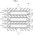
FIG. 1 is a sectional view illustrating a schematic structure of a first embodiment of a bipolar battery according to the present invention; -
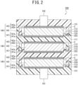
FIG. 2 is a sectional view illustrating a schematic structure of a second embodiment of the bipolar battery according to the present invention; and -
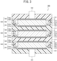
FIG. 3 is a sectional view illustrating a schematic structure of a third embodiment of the bipolar battery according to the present invention. - Embodiments of a bipolar battery according to the present invention will be described with reference to the drawings, but the present invention is not limited only to the embodiments to be described below with reference to the drawings.
- A first embodiment of the bipolar battery according to the present invention will be described with reference to
FIG. 1 . - As illustrated in
FIG. 1 , inside a bipolarlead acid battery 100 according to the present embodiment, a plurality ofsubstrates 111 each serving as a frame-plate forming a square flat plate shape and made of thermoplastic resin having sulfuric-acid resistance (e.g., polyethylene, polypropylene, polystyrene, polyvinyl chloride, polymethylmethacrylate (acryl resin), acrylonitrile-butadiene-styrene copolymer (ABS), polyamide (nylon), polycarbonate, and so on) is arranged to face each other at intervals. On one end side (inFIG. 1 , a lower end side) in an arrangement direction of thesubstrates 111 of the bipolarlead acid battery 100, afirst end plate 121 serving as a frame-plate forming a square flat plate shape and made of thermoplastic resin having sulfuric-acid resistance is arranged similarly to thesubstrates 111. On the other end side (inFIG. 1 , an upper end side) in the arrangement direction of thesubstrates 111 of the bipolarlead acid battery 100, asecond end plate 131 serving as a frame-plate forming a square flat plate shape and made of thermoplastic resin having sulfuric-acid resistance is arranged similarly to thesubstrates 111. - On the other surfaces (in
FIG. 1 , upper surfaces) of thesubstrates 111 and thefirst end plate 121, positive-electrode lead layers 141a made of lead or lead alloy, provided as metal layers for positive electrode, are disposed respectively. On the positive-electrode lead layers 141a, positiveactive material layers 141b containing an active material are disposed respectively. Apositive electrode 141 is formed by the positive-electrode lead layer 141a and the positiveactive material layer 141b. - On one surfaces (in
FIG. 1 , lower surfaces) of thesubstrates 111 and thesecond end plate 131, negative-electrode lead layers 142a made of lead or lead alloy, provided as metal layers for negative electrode, are disposed respectively. On the negative-electrode lead layers 142a, negativeactive material layers 142b containing an active material are disposed respectively. Anegative electrode 142 is formed by the negative-electrode lead layer 142a and the negativeactive material layer 142b. - An electrolyte layer 143 such as a glass-fiber mat impregnated with electrolyte such as sulfuric acid is disposed between the
positive electrode 141 and thenegative electrode 142. Cell members 140 are each formed by thepositive electrode 141, thenegative electrode 142, and the electrolyte layer 143. The cell members 140 are electrically connected in series to each other by well-known means. For example, thesubstrate 111 includes means via which the positive-electrode lead layer 141a is electrically connected to the negative-electrode lead layer 142a. Note that, inFIG. 1 , 101 indicates a positive electrode terminal, and 102 indicates a negative electrode terminal. - That is, the cell members 140 are connected in series to each other such that the cell members 140 and the frame-
plates positive electrode 141 and thenegative electrode 142, the frame-plates plates - On the other surfaces (in
FIG. 1 , the upper surfaces) of thesubstrates 111, respectiveouter walls 112 made of thermoplastic resin having sulfuric-acid resistance and forming a square frame shape along respective peripheral edges are integrally projected. On the one surfaces (inFIG. 1 , the lower surfaces) of thesubstrates 111, respective joiningwalls 113 made of thermoplastic resin having sulfuric-acid resistance are integrally projected such that the respective joiningwalls 113 are positioned closer to the inner side of thesubstrates 111 than the respectiveouter walls 112 on the other surfaces (inFIG. 1 , the upper surfaces) of thesubstrates 111 to surround respective peripheral edges of the cell members 140. - On the other surface (in
FIG. 1 , the upper surface) of thefirst end plate 121, anouter wall 122 made of thermoplastic resin having sulfuric-acid resistance and forming a square frame shape along a peripheral edge of thefirst end plate 121 is integrally projected. On the one surface (inFIG. 1 , the lower surface) of thesecond end plate 131, a joiningwall 133 made of thermoplastic resin having sulfuric-acid resistance is integrally projected such that the joiningwall 133 is positioned closer to the inner side of thesubstrate 111 facing thesecond end plate 131 than theouter wall 112 on the other surface (inFIG. 1 , the upper surface) of thesubstrate 111 and surrounds the peripheral edge of the cell member 140. - That is, the
outer wall FIG. 1 , an upper surface) of one frame-plate 111, 121 (inFIG. 1 , on the lower side) out of frame-plates facing each other, and the joiningwall FIG. 1 , on a lower surface) of the other frame-plate 111, 131 (inFIG. 1 , on the upper side) out of the frame-plates facing each other such that the joiningwall outer wall plate 111, 121 (inFIG. 1 , on the lower side) and surrounds the peripheral edge of the cell member 140 are provided. - A distal end (in
FIG. 1 a bottom end) of the joiningwall 133 of thesecond end plate 131 is joined to the other surface (inFIG. 1 , the upper surface) of thesubstrate 111 facing thesecond end plate 131, via an adhesive (e. g., an epoxy resin adhesive) 151 with sulfuric-acid resistance and provided as a joining material. A distal end (inFIG. 1 , a bottom end) of the joiningwall 113 of thesubstrate 111 facing thefirst end plate 121 is joined to the other surface (inFIG. 1 , the upper surface) of thefirst end plate 121 via the adhesive 151. A distal end (inFIG. 1 , a bottom end) of the joiningwall 113 of the other substrate 111 (inFIG. 1 , on the upper side) out of thesubstrates 111 facing each other is joined to the other surface (inFIG. 1 , the upper surface) of one substrate 111 (inFIG. 1 , on the lower side) via the adhesive 151. - That is, the joining
wall plate 111, 131 (inFIG. 1 , on the upper side) is joined to the facing surface (inFIG. 1 , the upper surface) of the one frame-plate 111, 121 (inFIG. 1 , on the lower side) via the adhesive (a joining material) 151. - Respective gaps are formed between the
outer wall 122 of thefirst end plate 121 and the one surface (inFIG. 1 , the lower surface) of thesubstrate 111 facing thefirst end plate 121 and between theouter wall 122 and the joiningwall 113. Respective gaps are formed between the one surface (inFIG. 1 , the lower surface) of thesecond end plate 131 and theouter wall 112 of thesubstrate 111 facing thesecond end plate 131 and between theouter wall 112 and the joiningwall 133 of thesecond end plate 131. Respective gaps are formed between theouter wall 112 of the one substrate 111 (inFIG. 1 , on the lower side) out of thesubstrates 111 facing each other and the one surface (inFIG. 1 , the lower surface) of the other substrate 111 (inFIG. 1 , on the upper side) and between theouter wall 112 and the joiningwall 113. - That is, a gap is formed between the
outer wall plate 111, 121 (inFIG. 1 , on the lower side) and the facing surface (inFIG. 1 , the lower surface) of the other frame-plate 111, 131 (inFIG. 1 , on the upper side), and a gap is formed between theouter wall plate 111, 121 (inFIG. 1 , on the lower side) and the joiningwall plate 111, 131 (inFIG. 1 , on the upper side). - Note that, in the present embodiment, each space surrounded and partitioned by the frame-
plates wall - In the bipolar
lead acid battery 100 according to the present embodiment, the joiningwall substrate 111 or thefirst end plate 121 facing the joiningwall adhesive 151. This makes it possible to prevent the electrolyte contained in the electrolyte layer 143 from leaking outside. Further, since theouter wall 112 is provided in a projecting manner along the peripheral edge on the facing surface (the other surface) of thesubstrate 111 or thefirst end plate 121, it is possible to prevent the adhesive 151 from stress being applied from outside, and consequently, it is possible to maintain hermetic seal and mechanical strength. - Accordingly, in the bipolar
lead acid battery 100 according to the present embodiment, it is not necessary to accommodate the bipolarlead acid battery 100 inside an outer packaging case or the like, and therefore, it is possible to reduce the parts and to achieve compactification of the bipolarlead acid battery 100. - Accordingly, with the bipolar
lead acid battery 100 according to the present embodiment, it is possible to achieve hermetic seal and mechanical strength in both and to increase energy density. - That is, in the bipolar
lead acid battery 100, theouter wall plate wall outer wall wall plate material 151 from stress being applied from outside, and consequently, it is possible to maintain hermetic seal and mechanical strength. As a result, it is not necessary to accommodate the bipolarlead acid battery 100 inside an outer packaging case or the like, and therefore, it is possible to reduce the parts and to achieve compactification of the bipolarlead acid battery 100. Consequently, it is possible to achieve hermetic seal and mechanical strength in both and to increase energy density. - Further, a gap is formed between the
outer wall substrate 111 or thesecond end plate 131 facing theouter wall outer wall wall outer wall - A second embodiment of the bipolar battery according to the present invention will be described with reference to
FIG. 2 . Note that, as for a part similarly to a part in the aforementioned embodiment, a reference sign similar to a reference sign used in the description of the aforementioned embodiment is used, and a redundant description similar to the description made in the aforementioned embodiment is omitted. - As illustrated in
FIG. 2 , on the other surface (inFIG. 2 , the upper surface) of thesubstrate 111 of a bipolarlead acid battery 200 according to the present embodiment, aninner wall 214 made of thermoplastic resin having sulfuric-acid resistance is integrally projected such that theinner wall 214 is positioned closer to the inner side of thesubstrate 111 than the joiningwall 113 on the one surface (inFIG. 2 , the lower surface) of thesubstrate 111 and surrounds the peripheral edge of the cell member 140. - On the other surface (in
FIG. 2 , the upper surface) of thefirst end plate 121, aninner wall 224 made of thermoplastic resin having sulfuric-acid resistance is integrally projected such that theinner wall 224 is positioned closer to the inner side of thefirst end plate 121 from theouter wall 112 on the one surface (inFIG. 2 , the lower surface) of thesubstrate 111 facing thefirst end plate 121 and surrounds the peripheral edge of the cell member 140. - That is, the
inner wall FIG. 2 , the upper surface) of the one frame-plate 111, 121 (inFIG. 2 , on the lower side) is provided such that theinner wall wall plate 111, 131 (inFIG. 2 , on the upper side) out of the frame-plates and surrounds the peripheral edge of the cell member 140. - A distal end side (in
FIG. 2 , the lower end side) of the joiningwall substrate 111 or thefirst end plate 121 facing the joiningwall outer wall inner wall material 252 that is a joining material made of thermoplastic resin that is the same material as thesubstrate 111, thefirst end plate 121, and the joiningwalls - That is, the joining
wall plate 111, 131 (inFIG. 2 , on the upper side) is joined to the facing surface (inFIG. 2 , the upper surface) of the one frame-plate 111, 121 (inFIG. 2 , on the lower side) via the fusing material (the joining material) 252. Further, the distal end side (inFIG. 2 , the lower end side) of the joiningwall outer wall FIG. 2 , the lower end side) of the joiningwall inner wall - Note that, in the present embodiment, each space partitioned by the
frame plates wall inner wall material 252 serves as the cell C and surrounds the cell member 140. - In the bipolar
lead acid battery 200 according to the present embodiment, the distal end side (inFIG. 2 , the lower end side) of the joiningwall outer wall inner wall FIG. 2 , the upper surface) of thesubstrate 111 or thefirst end plate 121, so that frictional heat is generated (friction of vibration) . Hereby, the distal end side of the joiningwall substrate 111 or thefirst end plate 121 that is between theouter wall inner wall material 252. - That is, the fusing
material 252 is a molten material generated by friction of vibration between the joiningwall plate 111, 131 (inFIG. 2 , on the upper side) and the facing surface (inFIG. 2 , the upper surface) of the one frame-plate 111, 121 (inFIG. 2 , on the lower side). - Then, the fusing
material 252 fuses the distal end side of the joiningwall substrate 111 or thefirst end plate 121 and also enters between the distal end side of the joiningwall outer wall inner wall wall outer wall inner wall 214, 224 (vibration welding). - In the bipolar
lead acid battery 200 manufactured by vibration welding about the present embodiment, the distal end side of the joiningwall inner wall outer wall wall substrate 111 or thefirst end plate 121, and hereby, a joining range of the joiningwall - Accordingly, with the bipolar
lead acid battery 200 according to the present embodiment, it is possible to yield an effect similar to that of the aforementioned first embodiment, and further, it is possible to more reliably prevent the electrolyte contained in the electrolyte layer 143 from leaking outside while stress from outside is buffered. - <Third Embodiment>
- A third embodiment of the bipolar battery according to the present invention will be described with reference to
FIG. 3 . Note that, as for a part similarly to a part in the aforementioned embodiment, a reference sign similar to a reference sign used in the description of the aforementioned embodiment is used, and a redundant description similar to the description made in the aforementioned embodiment is omitted. - As illustrated in
FIG. 3 , on the other surface (inFIG. 3 , the upper surface) of thesubstrate 111 of a bipolarlead acid battery 300 according to the present embodiment, anouter wall 312 made of thermoplastic resin having sulfuric-acid resistance and forming a square frame shape along the peripheral edge of thesubstrate 111 is integrally projected. On the other surface (inFIG. 3 , the upper surface) of thefirst end plate 121, anouter wall 322 made of thermoplastic resin having sulfuric-acid resistance and forming a square frame shape along the peripheral edge of thefirst end plate 121 is integrally projected. - The distal end (in
FIG. 3 , the lower end) of the joiningwall FIG. 3 , the upper surface) of thesubstrate 111 or thefirst end plate 121, an inner surface of theouter wall wall inner wall wall FIG. 3 , an upper end) of theouter wall FIG. 3 , the lower surface) of thesubstrate 111 or thesecond end plate 131, all via a fusingmaterial 352 that is a joining material made of thermoplastic resin that is the same material as thesubstrate 111, thefirst end plate 121, thesecond end plate 131, the joiningwall outer wall - That is, the joining
wall plate 111, 131 (inFIG. 3 , on the upper side) is joined to the facing surface (inFIG. 3 , the upper surface) of the one frame-plate 111, 121 (inFIG. 3 , on the lower side) . Theouter wall plate 111, 121 (inFIG. 3 , on the lower side) is joined to the joiningwall plate 111, 131 (inFIG. 3 , on the upper side). Theinner wall plate 111, 121 (inFIG. 3 , on the lower side) is joined to the joiningwall plate 111, 131 (inFIG. 3 , on the upper side). And theouter wall plate 111, 121 (inFIG. 3 , on the lower side) is joined to the facing surface (inFIG. 3 , the lower surface) of the other frame-plate 111, 131 (inFIG. 3 , on the upper side), all via the fusingmaterial 352. - Note that, in the present embodiment, each space partitioned by the
frame plates wall inner wall material 352 serves as the cell C and surrounds the cell member 140. - In the bipolar
lead acid battery 300 according to the present embodiment, when the distal end side (inFIG. 3 , the lower end side) of the joiningwall outer wall inner wall FIG. 3 , the upper end) of theouter wall FIG. 3 , the lower surface) of thesubstrate 111 or thesecond end plate 131. - Then, when the
substrate 111 or thesecond end plate 131 is vibrated against thesubstrate 111 or thefirst end plate 121 facing thesubstrate 111 or thesecond end plate 131, frictional heat is generated between the distal end of the joiningwall substrate 111 or thefirst end plate 121 and between the distal end of theouter wall substrate 111 or the second end plate 131 (friction of vibration). - Hereby, the distal end (in
FIG. 3 , the bottom end) of the joiningwall FIG. 3 , an upper-surface part) of thesubstrate 111 or thefirst end plate 121 that faces the distal end melt to generate a molten material, and the distal end (inFIG. 3 , the upper end) of theouter wall FIG. 3 , a lower-surface part) of thesubstrate 111 or thesecond end plate 131 that faces the distal end melt to generate a molten material, so that a fusingmaterial 352 is formed. - That is, the fusing
material 352 is a molten material generated by friction of vibration between the joiningwall plate 111, 131 (inFIG. 3 , on the upper side) and the facing surface (inFIG. 3 , the upper surface) of the one frame-plate 111, 121 (inFIG. 3 , on the lower side) and between theouter wall plate 111, 121 (inFIG. 3 , on the lower side) and the facing surface (inFIG. 3 , the lower surface) of the other frame-plate 111, 131 (inFIG. 3 , on the upper side). - Then, the fusing
material 352 fuses the distal end of the joiningwall substrate 111 or thefirst end plate 121, fuses the distal end of theouter wall substrate 111 or thesecond end plate 131, and also enters between the joiningwall outer wall inner wall wall outer wall inner wall 214, 224 (vibration welding). - In the bipolar
lead acid battery 300 manufactured by vibration welding about the present embodiment, the distal end of the joiningwall outer wall outer wall wall outer wall - Accordingly, in the bipolar
lead acid battery 300 according to the present embodiment, it is possible to further increase the joining range (area) of the joiningwall lead acid battery 200 according to the aforementioned second embodiment. - Accordingly, in the bipolar
lead acid battery 300 according to the present embodiment, although the buffering capacity of theouter wall wall lead acid battery 200 according to the aforementioned second embodiment. - Note that the bipolar battery according to the present invention is not limited to the bipolar lead
acid batteries material acid batteries - Further, a bipolar battery may be configured by replacing the adhesive 151 of the bipolar
lead acid battery 100 according to the first embodiment with the fusingmaterial acid batteries material acid batteries lead acid battery 100 according to the first embodiment. - That is, a bipolar battery can be configured by appropriately changing or replacing various technical matters of the bipolar
lead storage batteries - Further, the electrical conduction method included in the
substrate 111 is not limited to a specific method. For example, when the entire of the substrate contains conductive particles or conductive fiber, both sides of the substrate can be electrically connected. Further, a conductive member enabling electrical conduction can be incorporated into the substrate. - Since the bipolar battery according to the present invention can achieve hermetic seal and mechanical strength in both and also increase energy density, the bipolar battery can be used quite effectively for an industrial purpose.
-
- 100
- bipolar lead acid battery
- 101
- positive electrode terminal
- 102
- negative electrode terminal
- 111
- substrate
- 112
- outer wall
- 113
- joining wall
- 121
- first end plate
- 122
- outer wall
- 131
- second end plate
- 133
- joining wall
- 140
- cell member
- 141
- positive electrode
- 141a
- positive-electrode lead layer
- 141b
- positive active material layer
- 142
- negative electrode
- 142a
- negative-electrode lead layer
- 142b
- negative active material layer
- 143
- electrolyte layer
- 151
- adhesive
- 200
- bipolar lead acid battery
- 214
- inner wall
- 224
- inner wall
- 252
- fusing material
- 300
- bipolar lead acid battery
- 312
- outer wall
- 322
- outer wall
- 352
- fusing material
- C
- cell
Claims (10)
- A bipolar battery in which cell members are connected in series to each other by alternately stacking the cell members and frame-plates in multiple layers, the cell members each configured such that an electrolyte layer is provided between a positive electrode and a negative electrode, the frame-plates being made of resin and configured such that the cell members are accommodated in the frame plates, the bipolar battery comprising:an outer wall integrally projected along a peripheral edge on a facing surface of one frame plate out of frame plates facing each other; anda joining wall integrally projected on a facing surface of the other frame-plate out of the frame-plates facing each other, the joining wall being positioned inwardly from the outer wall of the one frame-plate and surrounding a peripheral edge of a corresponding one of the cell members, wherein the joining wall of the other frame-plate is joined to the facing surface of the one frame-plate via a joining material.
- The bipolar battery according to claim 1, wherein the joining material is provided between the outer wall of the one frame-plate and the joining wall of the other frame plate.
- The bipolar battery according to claim 1 or 2, comprising an inner wall integrally projected on the facing surface of the one frame-plate, the inner wall being positioned inwardly from the joining wall of the other frame-plate and surrounding the peripheral edge of the corresponding one of the cell members, wherein the inner wall of the one frame-plate is joined to the joining wall of the other frame-plate via the joining material.
- The bipolar battery according to any one of claims 1 to 3, wherein a gap is formed between the outer wall of the one frame-plate and the facing surface of the other frame-plate.
- The bipolar battery according to any one of claims 1 to 4, wherein the joining material is an adhesive or a fusing material.
- The bipolar battery according to claim 5, wherein the fusing material is a molten material generated by welding processing between the joining wall of the other frame-plate and the facing surface of the one frame-plate.
- The bipolar battery according to any one of claims 1 to 3, wherein the outer wall of the one frame-plate is joined to the facing surface of the other frame-plate via the joining material.
- The bipolar battery according to claim 7, wherein the joining material is an adhesive or a fusing material.
- The bipolar battery according to claim 8, wherein the fusing material is a molten material generated by welding processing between the joining wall of the other frame-plate and the facing surface of the one frame-plate and between the outer wall of the one frame-plate and the facing surface of the other frame-plate.
- The bipolar battery according to any one of claims 1 to 9, wherein the resin is thermoplastic resin.
Applications Claiming Priority (2)
| Application Number | Priority Date | Filing Date | Title |
|---|---|---|---|
| JP2020165687 | 2020-09-30 | ||
| PCT/JP2021/028488 WO2022070587A1 (en) | 2020-09-30 | 2021-07-30 | Bipolar storage battery |
Publications (2)
| Publication Number | Publication Date |
|---|---|
| EP4224593A1 true EP4224593A1 (en) | 2023-08-09 |
| EP4224593A4 EP4224593A4 (en) | 2025-07-02 |
Family
ID=80949876
Family Applications (1)
| Application Number | Title | Priority Date | Filing Date |
|---|---|---|---|
| EP21874890.3A Withdrawn EP4224593A4 (en) | 2020-09-30 | 2021-07-30 | BIPOLAR STORAGE BATTERY |
Country Status (7)
| Country | Link |
|---|---|
| US (1) | US20230223628A1 (en) |
| EP (1) | EP4224593A4 (en) |
| JP (1) | JP7665644B2 (en) |
| CN (1) | CN116325280A (en) |
| AU (1) | AU2021354234A1 (en) |
| BR (1) | BR112023004662A2 (en) |
| WO (1) | WO2022070587A1 (en) |
Family Cites Families (8)
| Publication number | Priority date | Publication date | Assignee | Title |
|---|---|---|---|---|
| JPH01195673A (en) * | 1988-01-29 | 1989-08-07 | Shin Kobe Electric Mach Co Ltd | Cell |
| JP3805275B2 (en) | 2002-04-30 | 2006-08-02 | 松下電器産業株式会社 | Batteries and battery modules |
| JP4373743B2 (en) * | 2003-09-09 | 2009-11-25 | 京セラ株式会社 | Battery case and battery |
| JP2005251465A (en) * | 2004-03-02 | 2005-09-15 | Nissan Motor Co Ltd | Bipolar battery |
| JP2005259379A (en) | 2004-03-09 | 2005-09-22 | Nissan Motor Co Ltd | Bipolar battery |
| SE530733C2 (en) | 2005-12-21 | 2008-08-26 | Effpower Ab | Method and apparatus for making a battery, as well as a battery |
| JP6070239B2 (en) * | 2012-02-22 | 2017-02-01 | 日産自動車株式会社 | Air battery |
| JP6946656B2 (en) * | 2017-02-15 | 2021-10-06 | 株式会社豊田自動織機 | Power storage module |
-
2021
- 2021-07-30 CN CN202180054402.8A patent/CN116325280A/en active Pending
- 2021-07-30 JP JP2022553503A patent/JP7665644B2/en active Active
- 2021-07-30 WO PCT/JP2021/028488 patent/WO2022070587A1/en not_active Ceased
- 2021-07-30 EP EP21874890.3A patent/EP4224593A4/en not_active Withdrawn
- 2021-07-30 BR BR112023004662A patent/BR112023004662A2/en not_active Application Discontinuation
- 2021-07-30 AU AU2021354234A patent/AU2021354234A1/en not_active Abandoned
-
2023
- 2023-03-23 US US18/188,867 patent/US20230223628A1/en not_active Abandoned
Also Published As
| Publication number | Publication date |
|---|---|
| WO2022070587A1 (en) | 2022-04-07 |
| CN116325280A (en) | 2023-06-23 |
| BR112023004662A2 (en) | 2023-04-18 |
| EP4224593A4 (en) | 2025-07-02 |
| JPWO2022070587A1 (en) | 2022-04-07 |
| US20230223628A1 (en) | 2023-07-13 |
| JP7665644B2 (en) | 2025-04-21 |
| AU2021354234A1 (en) | 2023-06-08 |
Similar Documents
| Publication | Publication Date | Title |
|---|---|---|
| CN110915025B (en) | Bus bar, battery module including the same, and battery pack including the battery module | |
| KR102619201B1 (en) | Secondary Battery and Battery Module Having the Same | |
| JP5534678B2 (en) | battery pack | |
| KR102529975B1 (en) | Case for secondary battery and battery module having the same | |
| KR100870354B1 (en) | Battery exterior material and secondary battery using same | |
| KR101734703B1 (en) | Battery Cell | |
| JP5105390B2 (en) | Thin secondary battery and battery module for large current discharge | |
| KR20130117637A (en) | Secondary battery, element for secondary battery applied for it and method of manufacturing the same | |
| KR20110089679A (en) | Battery cell assembly having a novel structure and a battery pack comprising the same | |
| CN101425601A (en) | Battery pack | |
| CN103972461A (en) | Rechargeable battery pack | |
| JP2014067591A (en) | Battery pack | |
| JP7540844B2 (en) | Battery module and battery pack including same | |
| KR20140129600A (en) | Secondary battery and Component for secondary battery applied for it | |
| JP2024500506A (en) | Battery module and battery pack containing it | |
| KR102328646B1 (en) | Pouch case and secondary battery including the same | |
| KR102252335B1 (en) | Pouch-typed Battery Cell Having Extended Protective Film | |
| KR20130122565A (en) | Pouch Type Lithium Secondary Battery | |
| AU2021354234A1 (en) | Bipolar storage battery | |
| KR102019391B1 (en) | Pouch-Typed Battery Cell of Double Case Structure | |
| EP4498501A1 (en) | Battery module and battery pack including same | |
| WO2019004296A1 (en) | Battery module and method for producing battery module | |
| KR20200058111A (en) | Battery pack and method for fabricating the same |
Legal Events
| Date | Code | Title | Description |
|---|---|---|---|
| STAA | Information on the status of an ep patent application or granted ep patent |
Free format text: STATUS: THE INTERNATIONAL PUBLICATION HAS BEEN MADE |
|
| PUAI | Public reference made under article 153(3) epc to a published international application that has entered the european phase |
Free format text: ORIGINAL CODE: 0009012 |
|
| STAA | Information on the status of an ep patent application or granted ep patent |
Free format text: STATUS: REQUEST FOR EXAMINATION WAS MADE |
|
| 17P | Request for examination filed |
Effective date: 20230316 |
|
| AK | Designated contracting states |
Kind code of ref document: A1 Designated state(s): AL AT BE BG CH CY CZ DE DK EE ES FI FR GB GR HR HU IE IS IT LI LT LU LV MC MK MT NL NO PL PT RO RS SE SI SK SM TR |
|
| DAV | Request for validation of the european patent (deleted) | ||
| DAX | Request for extension of the european patent (deleted) | ||
| A4 | Supplementary search report drawn up and despatched |
Effective date: 20250602 |
|
| RIC1 | Information provided on ipc code assigned before grant |
Ipc: H01M 50/198 20210101ALI20250526BHEP Ipc: H01M 50/121 20210101ALI20250526BHEP Ipc: H01M 50/193 20210101ALI20250526BHEP Ipc: H01M 50/209 20210101ALI20250526BHEP Ipc: H01M 50/103 20210101ALI20250526BHEP Ipc: H01M 4/02 20060101ALI20250526BHEP Ipc: H01M 8/0273 20160101ALI20250526BHEP Ipc: H01M 10/647 20140101ALI20250526BHEP Ipc: H01M 10/0585 20100101ALI20250526BHEP Ipc: H01M 10/04 20060101ALI20250526BHEP Ipc: H01M 10/18 20060101ALI20250526BHEP Ipc: H01M 10/12 20060101AFI20250526BHEP |
|
| STAA | Information on the status of an ep patent application or granted ep patent |
Free format text: STATUS: THE APPLICATION IS DEEMED TO BE WITHDRAWN |
|
| 18D | Application deemed to be withdrawn |
Effective date: 20251223 |