EP4224570A1 - Bipolar storage battery - Google Patents
Bipolar storage battery Download PDFInfo
- Publication number
- EP4224570A1 EP4224570A1 EP21875131.1A EP21875131A EP4224570A1 EP 4224570 A1 EP4224570 A1 EP 4224570A1 EP 21875131 A EP21875131 A EP 21875131A EP 4224570 A1 EP4224570 A1 EP 4224570A1
- Authority
- EP
- European Patent Office
- Prior art keywords
- bipolar
- electrode
- covering member
- storage battery
- positive electrode
- Prior art date
- Legal status (The legal status is an assumption and is not a legal conclusion. Google has not performed a legal analysis and makes no representation as to the accuracy of the status listed.)
- Withdrawn
Links
Images


Classifications
-
- H—ELECTRICITY
- H01—ELECTRIC ELEMENTS
- H01M—PROCESSES OR MEANS, e.g. BATTERIES, FOR THE DIRECT CONVERSION OF CHEMICAL ENERGY INTO ELECTRICAL ENERGY
- H01M10/00—Secondary cells; Manufacture thereof
- H01M10/06—Lead-acid accumulators
- H01M10/18—Lead-acid accumulators with bipolar electrodes
-
- H—ELECTRICITY
- H01—ELECTRIC ELEMENTS
- H01M—PROCESSES OR MEANS, e.g. BATTERIES, FOR THE DIRECT CONVERSION OF CHEMICAL ENERGY INTO ELECTRICAL ENERGY
- H01M10/00—Secondary cells; Manufacture thereof
- H01M10/06—Lead-acid accumulators
- H01M10/12—Construction or manufacture
-
- H—ELECTRICITY
- H01—ELECTRIC ELEMENTS
- H01M—PROCESSES OR MEANS, e.g. BATTERIES, FOR THE DIRECT CONVERSION OF CHEMICAL ENERGY INTO ELECTRICAL ENERGY
- H01M4/00—Electrodes
- H01M4/02—Electrodes composed of, or comprising, active material
- H01M4/14—Electrodes for lead-acid accumulators
-
- H—ELECTRICITY
- H01—ELECTRIC ELEMENTS
- H01M—PROCESSES OR MEANS, e.g. BATTERIES, FOR THE DIRECT CONVERSION OF CHEMICAL ENERGY INTO ELECTRICAL ENERGY
- H01M4/00—Electrodes
- H01M4/02—Electrodes composed of, or comprising, active material
- H01M4/64—Carriers or collectors
- H01M4/66—Selection of materials
- H01M4/68—Selection of materials for use in lead-acid accumulators
- H01M4/685—Lead alloys
-
- H—ELECTRICITY
- H01—ELECTRIC ELEMENTS
- H01M—PROCESSES OR MEANS, e.g. BATTERIES, FOR THE DIRECT CONVERSION OF CHEMICAL ENERGY INTO ELECTRICAL ENERGY
- H01M50/00—Constructional details or processes of manufacture of the non-active parts of electrochemical cells other than fuel cells, e.g. hybrid cells
- H01M50/10—Primary casings; Jackets or wrappings
- H01M50/116—Primary casings; Jackets or wrappings characterised by the material
- H01M50/121—Organic material
-
- H—ELECTRICITY
- H01—ELECTRIC ELEMENTS
- H01M—PROCESSES OR MEANS, e.g. BATTERIES, FOR THE DIRECT CONVERSION OF CHEMICAL ENERGY INTO ELECTRICAL ENERGY
- H01M50/00—Constructional details or processes of manufacture of the non-active parts of electrochemical cells other than fuel cells, e.g. hybrid cells
- H01M50/10—Primary casings; Jackets or wrappings
- H01M50/147—Lids or covers
- H01M50/155—Lids or covers characterised by the material
- H01M50/16—Organic material
-
- H—ELECTRICITY
- H01—ELECTRIC ELEMENTS
- H01M—PROCESSES OR MEANS, e.g. BATTERIES, FOR THE DIRECT CONVERSION OF CHEMICAL ENERGY INTO ELECTRICAL ENERGY
- H01M4/00—Electrodes
- H01M4/02—Electrodes composed of, or comprising, active material
- H01M2004/026—Electrodes composed of, or comprising, active material characterised by the polarity
- H01M2004/027—Negative electrodes
-
- H—ELECTRICITY
- H01—ELECTRIC ELEMENTS
- H01M—PROCESSES OR MEANS, e.g. BATTERIES, FOR THE DIRECT CONVERSION OF CHEMICAL ENERGY INTO ELECTRICAL ENERGY
- H01M4/00—Electrodes
- H01M4/02—Electrodes composed of, or comprising, active material
- H01M2004/026—Electrodes composed of, or comprising, active material characterised by the polarity
- H01M2004/028—Positive electrodes
-
- H—ELECTRICITY
- H01—ELECTRIC ELEMENTS
- H01M—PROCESSES OR MEANS, e.g. BATTERIES, FOR THE DIRECT CONVERSION OF CHEMICAL ENERGY INTO ELECTRICAL ENERGY
- H01M4/00—Electrodes
- H01M4/02—Electrodes composed of, or comprising, active material
- H01M2004/026—Electrodes composed of, or comprising, active material characterised by the polarity
- H01M2004/029—Bipolar electrodes
-
- Y—GENERAL TAGGING OF NEW TECHNOLOGICAL DEVELOPMENTS; GENERAL TAGGING OF CROSS-SECTIONAL TECHNOLOGIES SPANNING OVER SEVERAL SECTIONS OF THE IPC; TECHNICAL SUBJECTS COVERED BY FORMER USPC CROSS-REFERENCE ART COLLECTIONS [XRACs] AND DIGESTS
- Y02—TECHNOLOGIES OR APPLICATIONS FOR MITIGATION OR ADAPTATION AGAINST CLIMATE CHANGE
- Y02E—REDUCTION OF GREENHOUSE GAS [GHG] EMISSIONS, RELATED TO ENERGY GENERATION, TRANSMISSION OR DISTRIBUTION
- Y02E60/00—Enabling technologies; Technologies with a potential or indirect contribution to GHG emissions mitigation
- Y02E60/10—Energy storage using batteries
-
- Y—GENERAL TAGGING OF NEW TECHNOLOGICAL DEVELOPMENTS; GENERAL TAGGING OF CROSS-SECTIONAL TECHNOLOGIES SPANNING OVER SEVERAL SECTIONS OF THE IPC; TECHNICAL SUBJECTS COVERED BY FORMER USPC CROSS-REFERENCE ART COLLECTIONS [XRACs] AND DIGESTS
- Y02—TECHNOLOGIES OR APPLICATIONS FOR MITIGATION OR ADAPTATION AGAINST CLIMATE CHANGE
- Y02P—CLIMATE CHANGE MITIGATION TECHNOLOGIES IN THE PRODUCTION OR PROCESSING OF GOODS
- Y02P70/00—Climate change mitigation technologies in the production process for final industrial or consumer products
- Y02P70/50—Manufacturing or production processes characterised by the final manufactured product
Definitions
- An embodiment of the present invention relates to a bipolar storage battery.
- a bipolar lead storage battery includes a bipolar electrode including a positive electrode, a negative electrode, and a substrate (a bipolar plate) in which the positive electrode is provided on one surface and the negative electrode is provided on the other surface.
- a positive electrode of a conventional bipolar electrode is configured such that a positive-electrode lead layer 220 is disposed on one surface of a substrate 210 made of resin via an adhesive layer 240, and a positive active material (PAM) layer (not illustrated) is disposed on the positive-electrode lead layer 220.
- PAM positive active material
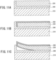
- the positive-electrode lead layer 220 might corrode due to sulfuric acid contained in an electrolytic solution, and a coating 260 of a corrosion product (lead oxide) might be generated on the surface of the positive-electrode lead layer 220 (see FIG. 11B ). Due to the growth of the coating 260 of the corrosion product, elongation (growth) might be caused in the positive-electrode lead layer 220.
- the electrolytic solution penetrates into an interface between the positive-electrode lead layer 220 and the adhesive layer 240, and this might result in that the corrosion of the positive-electrode lead layer 220 due to sulfuric acid further progresses (see FIG. 11C ).
- the corrosion reaches a back surface (a surface facing the substrate 210) of the positive-electrode lead layer 220, for example, battery performance might decrease due to the occurrence of a short circuit or the like.
- a surface where the corrosion of the positive-electrode lead layer 220 (the positive electrode) due to sulfuric acid progresses because the electrolytic solution penetrates into the interface between the positive-electrode lead layer 220 (the positive electrode) and the adhesive layer 240 due to the growth is hereinafter referred to as a "creepage surface” as appropriate. Further, a distance by which the corrosion progresses is referred to as a "creepage distance” as appropriate.
- An object of the present invention is to provide a bipolar storage battery in which, even when growth occurs in a positive electrode due to corrosion caused by sulfuric acid contained in an electrolytic solution, the electrolytic solution is hard to penetrate into an interface between the positive electrode and an adhesive and battery performance is hard to decrease.
- a bipolar storage battery is a bipolar storage battery including a bipolar electrode including a positive electrode, a negative electrode, and a bipolar plate in which the positive electrode is provided on one surface and the negative electrode is provided on the other surface, and the bipolar electrode includes a covering member configured to cover a peripheral part of an opposite surface of the positive electrode in close contact with the peripheral part, the opposite surface being opposite to a surface, of the positive electrode, bonded to the bipolar plate.
- a bipolar storage battery includes a bipolar electrode including a positive electrode, a negative electrode, and a bipolar plate in which the positive electrode is provided on one surface and the negative electrode is provided on the other surface, and the bipolar electrode includes a covering member configured to cover a peripheral part of an opposite surface of the positive electrode in close contact with the peripheral part, the opposite surface being opposite to a surface, of the positive electrode, bonded to the bipolar plate.
- FIG. 1 is a sectional view to describe the structure of the bipolar lead storage battery 1 according to the embodiment of the present invention.
- the bipolar lead storage battery 1 illustrated in FIG. 1 includes: a first plate unit in which a negative electrode 110 is fixed to a first plate (an end plate) 11 having a flat plate shape; second plate units in each of which an electrolytic layer 105 is fixed to the inside of a second plate (a spacer) 12 having a frame plate shape; third plate units in each of which a bipolar electrode 130 is fixed to the inside of a third plate (a rim) 13 having a frame plate shape, the bipolar electrode 130 being configured such that a positive electrode 120 is provided on one surface of a substrate (a bipolar plate) 111 and a negative electrode 110 is provided on the other surface; and a fourth plate unit in which the positive electrode 120 is fixed to a fourth plate (an end plate) 14 having a flat plate shape.
- the bipolar lead storage battery 1 having a generally rectangular solid shape is formed, for example.
- the number of the second plate units to be provided and the number of the third plate units to be provided are set such that a power storage capacity of the bipolar lead storage battery 1 achieves a desired value.
- a negative electrode terminal 107 is fixed to the first plate 11, and the negative electrode 110 fixed to the first plate 11 is electrically connected to the negative electrode terminal 107.
- a positive electrode terminal 108 is fixed to the fourth plate 14, and the positive electrode 120 fixed to the fourth plate 14 is electrically connected to the positive electrode terminal 108.
- the first plate 11 to the fourth plate 14 are formed of well-known molding resin, for example.
- the first plate 11 to the fourth plate 14 are fixed to each other such that an inner part is sealed by an appropriate method to prevent an electrolytic solution from flowing outside.
- the electrolytic layer 105 is constituted by a glass-fiber mat impregnated with an electrolytic solution containing sulfuric acid, for example.
- the bipolar plate 111 is made of thermoplastic resin, for example.
- the thermoplastic resin to form the bipolar plate 111 include an acrylonitrile-butadiene-styrene copolymer (ABS resin) and polypropylene, for example. These thermoplastic resins are excellent in moldability and also excellent in sulfuric-acid resistance. Accordingly, even when the electrolytic solution makes contact with the bipolar plate 111, the bipolar plate 111 is hard to decompose, deteriorate, or corrode.
- the positive electrode 120 includes a positive-electrode lead layer 101 as a positive-electrode current collector, the positive-electrode lead layer 101 being made of lead or lead alloy and disposed on the one surface of the bipolar plate 111, and a positive active material layer 103 disposed on the positive-electrode lead layer 101.
- the positive-electrode lead layer 101 is bonded to the one surface of the bipolar plate 111 via an adhesive 140 provided between the one surface of the bipolar plate 111 and the positive-electrode lead layer 101. Accordingly, on the one surface (a surface facing upward on the plane of paper in the figures such as FIG. 2 to be described later) of the bipolar plate 111, the adhesive 140, the positive-electrode lead layer 101, and the positive active material layer 103 are provided in a laminated manner in this order.
- the negative electrode 110 includes a negative-electrode lead layer 102 as a negative-electrode current collector, the negative-electrode lead layer 102 being made of lead or lead alloy and disposed on the other surface of the bipolar plate 111, and a negative active material (NAM) layer 104 disposed on the negative-electrode lead layer 102.
- the negative-electrode lead layer 102 is bonded to the other surface of the bipolar plate 111 via the adhesive 140 provided between the other surface of the bipolar plate 111 and the negative-electrode lead layer 102.
- the positive electrode 120 is electrically connected to the negative electrode 110 by an appropriate method.
- the bipolar electrode 130 is constituted by the bipolar plate 111, the positive-electrode lead layer 101, the positive active material layer 103, the negative-electrode lead layer 102, and the negative active material layer 104, as described above.
- a bipolar electrode is an electrode having functions both as a positive electrode and a negative electrode in a single electrode.
- the bipolar lead storage battery 1 according to the embodiment of the present invention has a battery configuration in which cell members are connected in series to each other by assembling the cell members such that the cell members are provided alternately in a laminated manner, the cell members being each configured such that the electrolytic layer 105 is provided between the positive electrode 120 and the negative electrode 110.
- the bipolar lead storage battery 1 has a structure in which penetration of the electrolytic solution into an interface between the positive-electrode lead layer 101 and the adhesive 140 is restrained even when growth occurs in the positive-electrode lead layer 101 due to corrosion caused by sulfuric acid contained in the electrolytic solution.
- the following describes details of the structure in which the penetration of the electrolytic solution is restrained, with reference to FIGS. 2 , 3 .
- FIG. 2 is an enlarged sectional view of the bipolar electrode 130 and illustrates a structure of an essential part of the bipolar lead storage battery 1 according to the first embodiment.
- FIG. 3 is a view to describe, in terms of the bipolar lead storage battery 1 according to the first embodiment, a state where the penetration of the electrolytic solution into the interface between the positive electrode 120 and the adhesive 140 is restrained even when growth occurs in the positive electrode 120 due to corrosion caused by sulfuric acid contained in the electrolytic solution.
- the positive-electrode lead layer 101 and the positive active material layer 103 are collectively considered as the positive electrode 120.
- a covering member 150 is provided to cover a peripheral part of the positive-electrode lead layer 101, the peripheral part being exposed in a peripheral part of the positive active material layer 103, when the covering member 150 is provided in a laminated manner, but the covering member 150 should be provided to cover at least the peripheral part of the positive-electrode lead layer 101 as such.
- the covering member 150 may be provided to cover the peripheral part of the positive electrode 120, and, for example, the covering member 150 can be also provided to cover the peripheral part of the positive active material layer 103. Further, the negative electrode 110 formed on the other surface of the bipolar plate 111 is not illustrated.
- the bipolar electrode 130 illustrated in FIG. 2 is configured such that the bipolar plate 111, the adhesive 140, the positive electrode 120, and the covering member 150 are sequentially provided in a laminated manner.
- the bipolar plate 111 extends horizontally on the figure, and a right side part of the bipolar plate 111 is not illustrated.
- the positive electrode 120 is bonded, via the adhesive 140, onto a part constituting the one surface of the bipolar plate 111 and extending horizontally. Further, the adhesive 140 is also provided in a part surrounding a peripheral edge part 120b of a peripheral part 120a of the positive electrode 120 and extending in a vertical direction of the bipolar plate 111, as well as between the one surface of the bipolar plate 111 and a surface, of the positive electrode 120, facing the one surface of the bipolar plate 111.
- the covering member 150 is provided such that the covering member 150 covers the peripheral part 120a in close contact with the peripheral part 120a on a surface (hereinafter, this surface is referred to as an "opposite surface 120c" appropriately) of the positive electrode 120, the surface being opposite from a surface, of the positive electrode 120, bonded to the bipolar plate 111.
- One end part 150a side of a surface, of the covering member 150, facing the peripheral part 120a makes contact with the adhesive 140 provided in an extending manner in the vertical direction from the bipolar plate 111. That is, the covering member 150 is provided to cover the peripheral part 120a of the positive electrode 120.
- the covering member 150 be disposed to press against the positive electrode 120. Since the covering member 150 makes close contact with the peripheral part 120a of the positive electrode 120, even when a coating 160 of a corrosion product (lead oxide) is generated on the surface of the positive electrode 120 as illustrated in FIG. 3 , growth of the coating 160 of the corrosion product is restrained by the covering member 150, and hereby, the coating 160 of the corrosion product is restrained from growing to the peripheral part 120a.
- a corrosion product lead oxide
- the positive electrode 120 is hard to be separated from the adhesive 140, and hereby, the electrolytic solution is restrained from penetrating into the interface between the positive electrode 120 and the adhesive 140. Therefore, such a defect that battery performance decreases due to the occurrence of a short circuit or the like is hard to occur, the short circuit being caused when the corrosion caused by sulfuric acid reaches a back surface (a surface of the positive electrode 120, the surface facing the bipolar plate 111) of the positive electrode 120.
- the peripheral part 120a of the positive electrode 120 is an outer part of the opposite surface 120c. Accordingly, when the positive electrode 120 is regarded as a plane, the peripheral part 120a has a frame shape surrounding four sides of the positive electrode 120.
- the covering member 150 when the covering member 150 covers even just part of the peripheral part 120a having a frame shape, the aforementioned effect is yielded. However, it is more preferable that the covering member 150 cover the entire of the peripheral part 120a having a frame shape, and this further successfully yields the aforementioned effect and makes it extremely hard to decrease the battery performance.
- FIG. 4 is a plan view of the bipolar electrode 130 to describe the structure of the essential part of the bipolar lead storage battery 1 according to the first embodiment. As illustrated in FIG. 4 , it is more preferable that the covering member 150 have a frame shape that covers the peripheral part 120a of the positive electrode 120.
- the covering member 150 should have sulfuric-acid resistance by which the covering member 150 is hard to be corroded by sulfuric acid, and examples of a material for the covering member 150 include resin, metal (e.g., stainless steel), and ceramic having sulfuric-acid resistance, for example.
- an acrylonitrile-butadiene-styrene copolymer (ABS resin), polypropylene, or the like can be used, for example.
- ABS resin acrylonitrile-butadiene-styrene copolymer
- polypropylene or the like
- thermoplastic resins are excellent in moldability and also excellent in sulfuric-acid resistance. Accordingly, even when the electrolytic solution makes contact with the covering member 150, the covering member 150 is hard to decompose, deteriorate, or corrode.
- a region, of the positive electrode 120, making contact with the covering member 150 is a region including the peripheral part 120a and having a preset distance from the peripheral edge part 120b. More specifically, as illustrated in FIG. 2 , a region, provided on the opposite surface 120c, where the covering member 150 makes close contact with the positive electrode 120 is at least a region indicated by a distance L1 from the peripheral edge part 120b of the positive electrode 120 to the other end part 150b of the covering member 150 on the opposite surface 120c.
- the distance L1 is 4.6 mm or more. Further, it is more desirable that the distance L1 be less than 10 mm.
- the distance L1 is set to the range equal to or more than 4.6 mm but less than 10 mm.
- the adhesive 140 is provided in a region indicated by a distance L2 between the positive electrode 120 and a part extending in the vertical direction from the bipolar plate 111, and the covering member 150 also makes close contact with the adhesive 140 provided in this region.
- a distance necessary to prevent the penetration of sulfuric acid is the distance L1 in relation to the creepage distance, and the distance L2 can be set optionally.
- a distance L3 indicative of the thickness of the covering member 150 is formed to be equal to or more than 0.5 mm but equal to or less than 8.0 mm.
- the reason why the thickness of the covering member 150 is set to such a range is as follows: in a case where the thickness of the covering member 150 is smaller than 0.5 mm, when the electrolytic solution penetrates into an interface between the opposite surface 120c of the positive electrode 120 and the covering member 150, there is a possibility that the covering member 150 rises. In the meantime, it is also conceivable that, when the thickness of the covering member 150 is thicker than 8.0 mm, this might affect a structure around the bipolar electrode 130.
- the covering member 150 in the region including the peripheral part 120a of the positive electrode 120 as such, even when the growth occurs, it is possible to prevent such a situation that the positive electrode 120 is separated from the covering member 150 by the electrolytic solution penetrating into the interface between the positive electrode 120 and the covering member 150.
- the distance L1 from the peripheral edge part 120b of the positive electrode 120 to the other end part 150b of the covering member 150 on the opposite surface 120c is set to be equal to or more than 4.6 mm but less than 10 mm.
- the covering member 150 has a predetermined thickness, even when the growth occurs in the positive electrode 120 due to corrosion caused by sulfuric acid contained in the electrolytic solution, the covering member 150 is not stripped off, and hereby, the electrolytic solution is further restrained from penetrating into the interface between the positive electrode 120 and the covering member 150.
- the covering member 150 is disposed directly on the peripheral part 120a of the positive electrode 120, as illustrated in FIG. 2 .
- the adhesive 140 may be provided between the peripheral part 120a and the covering member 150 such that the peripheral part 120a is bonded to the covering member 150 via the adhesive 140.
- FIG. 5 is an enlarged sectional view of the bipolar electrode 130 and illustrates a structure of an essential part of the modification of the bipolar lead storage battery 1 according to the first embodiment.
- the adhesive 140 disposed between the peripheral part 120a and the covering member 150 is integrated with the adhesive 140 provided between the one surface of the bipolar plate 111 and the positive electrode 120.
- an end part of the adhesive 140 disposed, on the peripheral edge part 120b side, between the one surface of the bipolar plate 111 and the positive electrode 120 extends to between the peripheral part 120a of the opposite surface 120c and the covering member 150 and bonds the peripheral part 120a to the covering member 150.
- the covering member 150 is fixed to the bipolar plate 111 via the adhesive 140.
- the adhesive provided between the peripheral part 120a and the covering member 150 and the adhesive 140 provided between the one surface of the bipolar plate 111 and the positive electrode 120 may not be continuous with each other and may be provided separately.
- the covering member 150 more strongly makes close contact with the peripheral part 120a, and the coating 160 of the corrosion product is restrained still more from growing to the peripheral part 120a.
- the same constituent as a constituent described in the first embodiment described above has the same reference sign as a reference sign used in the first embodiment, and a redundant description about the same constituent is omitted.
- FIG. 6 is an enlarged sectional view of the bipolar electrode 130 and illustrates a structure of an essential part of the second embodiment of the bipolar lead storage battery 1 according to the present invention.
- the bipolar plate 111 has a flat plate shape, but the bipolar plate 111 in the second embodiment has a shape having a frame 170 formed in a flange shape at a peripheral edge part.
- a flange-shaped plate portion extends in a direction perpendicular to the one surface of the bipolar plate 111 from a peripheral edge part of the bipolar plate 111, and the plate portion is the frame 170. Therefore, the frame 170 is disposed to surround the peripheral edge part 120b of the positive electrode 120. Note that the frame 170 is made of the same material as the bipolar plate 111, e.g., resin or the like.
- the covering member 150 is fixed to the frame 170. Accordingly, the covering member 150 is easily disposed to press against the positive electrode 120. By disposing the covering member 150 such that the covering member 150 presses against the positive electrode 120, the coating 160 of the corrosion product is restrained still more from growing to the peripheral part 120a.
- the covering member 150 can be also fixed to the frame 170 by an adhesive.
- the adhesive via which the covering member 150 is fixed to the frame 170 and the adhesive 140 via which the bipolar plate 111 is fixed to the positive electrode 120 may be integrated with each other as illustrated in FIG. 6 or may be provided separately.
- the frame 170 and the bipolar plate 111 may be an integrated member as illustrated in FIG. 6 or may be separated members. Further, the frame 170 in FIG. 6 illustrates a state where the plate portion extends in a flange shape in the direction perpendicular to the one surface of the bipolar plate 111 from the peripheral edge part of the bipolar plate 111, but the frame 170 may include a state where the plate portion extends in a flange shape in a direction perpendicular to the other surface.
- the same constituent as a constituent described in the first and second embodiments has the same reference sign as a reference sign used in the first and second embodiments described above, and a redundant description about the same constituent is omitted.
- FIG. 7 is an enlarged sectional view of the bipolar electrode 130 and illustrates a structure of an essential part of the third embodiment of the bipolar lead storage battery 1 according to the present invention.
- the covering member 150 and the frame 170 are separated members, but in the third embodiment, the covering member 150 is formed of a member integrated with the frame 170.
- the covering member 150 is made of the same material as the frame 170. With such a configuration, the covering member 150 is more easily disposed to press against the positive electrode 120, as described above. Accordingly, by disposing the covering member 150 such that the covering member 150 presses against the positive electrode 120, the coating 160 of the corrosion product is restrained still more from growing to the peripheral part 120a.
- the same constituent as a constituent described in the first to third embodiments described above has the same reference sign as a reference sign used in the first to third embodiments, and a redundant description about the same constituent is omitted.
- FIG. 8 is an enlarged sectional view of the bipolar electrode 130 and illustrates a structure of an essential part of the fourth embodiment of the bipolar lead storage battery 1 according to the present invention.
- the covering member 150 is formed of resin, metal, or ceramic having sulfuric-acid resistance, but in the fourth embodiment, the covering member 150 is formed of a hardened object of an adhesive.
- the adhesive when the adhesive is applied to the peripheral part 120a and is hardened to be turned into the covering member 150, it is possible to yield an effect similar to that of the covering member 150 formed of resin, metal, or ceramic having sulfuric-acid resistance.
- the adhesive to form the covering member 150 may be integrated with the adhesive 140 via which the bipolar plate 111 is bonded to the positive electrode 120 as illustrated in FIG. 8 .
- the adhesive to form the covering member 150 and the adhesive 140 via which the bipolar plate 111 is bonded to the positive electrode 120 may not be continuous with each other and may be provided separately.
- the covering member 150 is formed of the adhesive 140, the covering member 150 more strongly makes close contact with the peripheral part 120a, and the coating 160 of the corrosion product is restrained still more from growing to the peripheral part 120a.
- the same constituent as a constituent described in the first to fourth embodiment described above has the same reference sign as a reference sign used in the first to fourth embodiments, and a redundant description about the same constituent is omitted.
- FIG. 9 is an enlarged sectional view of the bipolar electrode 130 and illustrates a structure of an essential part of the fifth embodiment of the bipolar lead storage battery 1 according to the present invention.
- the covering member 150 in the fifth embodiment is formed of a hardened object of an adhesive, similarly to the fourth embodiment. Further, the bipolar plate 111 including the frame 170 is used.
- the adhesive when the adhesive is applied to the peripheral part 120a and is hardened to be turned into the covering member 150, it is possible to yield an effect similar to that of the covering member 150 formed of resin, metal, or ceramic having sulfuric-acid resistance.
- the adhesive 140 forming the covering member 150 is also fixed to the frame 170.
- the covering member 150 more strongly makes close contact with the peripheral part 120a, and the coating 160 of the corrosion product is restrained still more from growing to the peripheral part 120a.
- the same constituent as a constituent described in the first to fifth embodiments described above has the same reference sign as a reference sign used in the first to fifth embodiments, and a redundant description about the same constituent is omitted.
- the modification of the first embodiment illustrated in FIG. 5 as described above deals with an example in which the adhesive 140 is provided between the covering member 150 and the opposite surface 120c of the positive electrode 120, but the sixth embodiment deals with an example in which the bipolar plate 111 including the frame 170 is used.
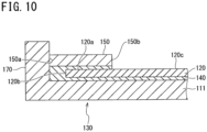
- FIG. 10 is an enlarged sectional view of the bipolar electrode 130 and illustrates a structure of an essential part of the sixth embodiment of the bipolar lead storage battery 1 according to the present invention.
- the bipolar electrode 130 in the sixth embodiment is configured such that the adhesive 140 is provided between the covering member 150 and the opposite surface 120c of the positive electrode 120, and the one end part 150a of the covering member 150 is fixed to the frame 170.
- the covering member 150 is provided on the opposite surface 120c of the positive electrode 120 via the adhesive 140 and is fixed to the frame 170. Accordingly, the covering member 150 more strongly makes close contact with the peripheral part 120a, and the covering member 150 is easily disposed to press against the positive electrode 120. Accordingly, the coating 160 of the corrosion product is restrained still more from growing to the peripheral part 120a.
- the bipolar lead storage batteries according to the first to sixth embodiments were subjected to a cycle test in which application and non-application of potential are repeated alternatingly, continuously for four weeks under the environment of 60°.
- corrosion caused by sulfuric acid did not reach the back surface of the positive electrode 120, so that the battery performance did not decrease.
- the electrolytic solution is hard to penetrate into the interface between the positive electrode and the adhesive, and the battery performance is hard to decrease.
- the adhesive 140 used in the bipolar lead storage battery 1 there is, for example, a hardened object of a reaction-curable adhesive configured to cure by a reaction between a base compound containing epoxy resin and a hardening agent containing an amine compound.
- the hardened object has such a property that the hardened object is hard to be corroded by sulfuric acid, and sulfuric acid is hard to penetrate into the interface between the positive electrode 120 and the adhesive 140. Further, the hardened object is hard to decompose, deteriorate, or corrode even when the hardened object makes contact with the electrolytic solution.
- the positive electrode 120 strongly makes close contact with the adhesive 140, even when the growth occurs in the positive electrode 120 due to corrosion caused by sulfuric acid contained in the electrolytic solution, the electrolytic solution is restrained from penetrating into the interface between the positive electrode 120 and the adhesive 140. Further, such a defect that the battery performance decreases due to the occurrence of a short circuit or the like is hard to occur, the short circuit being caused when the corrosion caused by sulfuric acid reaches the surface, of the positive electrode 120, facing the bipolar plate 111.
- the epoxy resin contained in the base compound may be, for example, at least either of bisphenol A epoxy resin and bisphenol F epoxy resin.
- As the epoxy resin one type may be used solely, or two or more types may be used in combination.
- the amine compound contained in the hardening agent may be, for example, an aliphatic polyamine compound, an alicyclic polyamine compound, or an aromatic polyamine compound.
- One of the amine compounds may be used solely, or two or more of the amine compounds may be used in combination.
- aliphatic polyamine compound examples include aliphatic primary amine such as triethylenetetramine (C 6 H 18 N 4 ), aliphatic secondary amine such as triethylenetetramine, and so on.
- aliphatic primary amine such as triethylenetetramine (C 6 H 18 N 4 ), aliphatic secondary amine such as triethylenetetramine, and so on.
- alicyclic polyamine compound examples include alicyclic primary amine such as isophorone diamine (C 10 H 22 N 2 ).
- aromatic polyamine compound examples include aromatic primary amine such as diaminodiphenylmethane (C 13 H 14 N 2 ).
- the description in the embodiments of the present invention deals with the bipolar lead storage battery as an example.
- the above description also applies to other storage batteries using other metals (e.g., aluminum, copper, nickel), alloy, or conductive resin for a current collector instead of lead, naturally, the present invention does not preclude the application.
Landscapes
- Chemical & Material Sciences (AREA)
- Chemical Kinetics & Catalysis (AREA)
- Electrochemistry (AREA)
- General Chemical & Material Sciences (AREA)
- Engineering & Computer Science (AREA)
- Manufacturing & Machinery (AREA)
- Materials Engineering (AREA)
- Secondary Cells (AREA)
- Saccharide Compounds (AREA)
Abstract
Description
- An embodiment of the present invention relates to a bipolar storage battery.
- A bipolar lead storage battery includes a bipolar electrode including a positive electrode, a negative electrode, and a substrate (a bipolar plate) in which the positive electrode is provided on one surface and the negative electrode is provided on the other surface. As illustrated in
FIG. 11A , a positive electrode of a conventional bipolar electrode is configured such that a positive-electrode lead layer 220 is disposed on one surface of asubstrate 210 made of resin via anadhesive layer 240, and a positive active material (PAM) layer (not illustrated) is disposed on the positive-electrode lead layer 220. - PTL 1:
WO 2013/073420 - In the bipolar lead storage battery as described above, the positive-
electrode lead layer 220 might corrode due to sulfuric acid contained in an electrolytic solution, and acoating 260 of a corrosion product (lead oxide) might be generated on the surface of the positive-electrode lead layer 220 (seeFIG. 11B ). Due to the growth of thecoating 260 of the corrosion product, elongation (growth) might be caused in the positive-electrode lead layer 220. - Further, when the positive-
electrode lead layer 220 is separated from theadhesive layer 240 due to the growth, the electrolytic solution penetrates into an interface between the positive-electrode lead layer 220 and theadhesive layer 240, and this might result in that the corrosion of the positive-electrode lead layer 220 due to sulfuric acid further progresses (seeFIG. 11C ). As a result, when the corrosion reaches a back surface (a surface facing the substrate 210) of the positive-electrode lead layer 220, for example, battery performance might decrease due to the occurrence of a short circuit or the like. - Note that, here, a surface where the corrosion of the positive-electrode lead layer 220 (the positive electrode) due to sulfuric acid progresses because the electrolytic solution penetrates into the interface between the positive-electrode lead layer 220 (the positive electrode) and the
adhesive layer 240 due to the growth is hereinafter referred to as a "creepage surface" as appropriate. Further, a distance by which the corrosion progresses is referred to as a "creepage distance" as appropriate. - An object of the present invention is to provide a bipolar storage battery in which, even when growth occurs in a positive electrode due to corrosion caused by sulfuric acid contained in an electrolytic solution, the electrolytic solution is hard to penetrate into an interface between the positive electrode and an adhesive and battery performance is hard to decrease.
- A bipolar storage battery according to one aspect of the present invention is a bipolar storage battery including a bipolar electrode including a positive electrode, a negative electrode, and a bipolar plate in which the positive electrode is provided on one surface and the negative electrode is provided on the other surface, and the bipolar electrode includes a covering member configured to cover a peripheral part of an opposite surface of the positive electrode in close contact with the peripheral part, the opposite surface being opposite to a surface, of the positive electrode, bonded to the bipolar plate.
- In the present invention, a bipolar storage battery includes a bipolar electrode including a positive electrode, a negative electrode, and a bipolar plate in which the positive electrode is provided on one surface and the negative electrode is provided on the other surface, and the bipolar electrode includes a covering member configured to cover a peripheral part of an opposite surface of the positive electrode in close contact with the peripheral part, the opposite surface being opposite to a surface, of the positive electrode, bonded to the bipolar plate. By employing such a configuration, it is possible to secure a contact range between a positive-electrode lead layer and a positive active material layer and to prevent penetration of the electrolytic solution as much as possible. Accordingly, even when growth occurs in the positive electrode due to corrosion caused by sulfuric acid contained in the electrolytic solution, the electrolytic solution is hard to penetrate into an interface between the positive electrode and an adhesive, and battery performance is hard to decrease.
-
-
FIG. 1 is a sectional view to describe a structure of a bipolar lead storage battery according to an embodiment of the present invention; -
FIG. 2 is an enlarged sectional view of a bipolar electrode and illustrates a structure of an essential part of a bipolar lead storage battery according to a first embodiment of the present invention; -
FIG. 3 is a view to describe, in terms of the bipolar lead storage battery according to the first embodiment of the present invention, a state where penetration of an electrolytic solution into an interface between a positive electrode and an adhesive is restrained even when growth occurs in the positive electrode due to corrosion caused by sulfuric acid contained in the electrolytic solution; -
FIG. 4 is a plan view of the bipolar electrode to describe a structure of an essential part of the bipolar lead storage battery according to the first embodiment of the present invention; -
FIG. 5 is an enlarged sectional view of the bipolar electrode and illustrates a structure of an essential part of a modification of the bipolar lead storage battery according to the first embodiment of the present invention; -
FIG. 6 is an enlarged sectional view of a bipolar electrode and illustrates a structure of an essential part of a second embodiment of the bipolar lead storage battery according to the present invention; -
FIG. 7 is an enlarged sectional view of a bipolar electrode and illustrates a structure of an essential part of a third embodiment of the bipolar lead storage battery according to the present invention; -
FIG. 8 is an enlarged sectional view of a bipolar electrode and illustrates a structure of an essential part of a fourth embodiment of the bipolar lead storage battery according to the present invention; -
FIG. 9 is an enlarged sectional view of a bipolar electrode and illustrates a structure of an essential part of a fifth embodiment of the bipolar lead storage battery according to the present invention; -
FIG. 10 is an enlarged sectional view of a bipolar electrode and illustrates a structure of an essential part of a sixth embodiment of the bipolar lead storage battery according to the present invention; and -
FIG. 11A, 11B and 11C are view to describe, in terms of a conventional bipolar lead storage battery, a state where an electrolytic solution penetrates into an interface between a positive-electrode lead layer and an adhesive as a result of the occurrence of growth in the positive-electrode lead layer due to corrosion caused by sulfuric acid contained in the electrolytic solution. - The following describes embodiments of the present invention in detail with reference to the drawings. Note that the embodiments to be described below describe examples of the present invention. Further, various changes or improvements can be added to the present embodiments, and the embodiments with the changes or improvements can be also included in the present invention. The embodiments and their modifications are included in the scope and the gist of the invention and are also included in the invention described in the claims and in its equivalent range. Note that the following description deals with a lead storage battery as an example from among various storage batteries.
- A structure of a bipolar
lead storage battery 1 according to an embodiment of the present invention will be described with reference toFIG. 1. FIG. 1 is a sectional view to describe the structure of the bipolarlead storage battery 1 according to the embodiment of the present invention. - The bipolar
lead storage battery 1 illustrated inFIG. 1 includes: a first plate unit in which anegative electrode 110 is fixed to a first plate (an end plate) 11 having a flat plate shape; second plate units in each of which anelectrolytic layer 105 is fixed to the inside of a second plate (a spacer) 12 having a frame plate shape; third plate units in each of which abipolar electrode 130 is fixed to the inside of a third plate (a rim) 13 having a frame plate shape, thebipolar electrode 130 being configured such that apositive electrode 120 is provided on one surface of a substrate (a bipolar plate) 111 and anegative electrode 110 is provided on the other surface; and a fourth plate unit in which thepositive electrode 120 is fixed to a fourth plate (an end plate) 14 having a flat plate shape. - When the second plate units and the third plate units are alternately provided in a laminated manner between the first plate unit and the fourth plate unit, the bipolar
lead storage battery 1 having a generally rectangular solid shape is formed, for example. The number of the second plate units to be provided and the number of the third plate units to be provided are set such that a power storage capacity of the bipolarlead storage battery 1 achieves a desired value. - A
negative electrode terminal 107 is fixed to thefirst plate 11, and thenegative electrode 110 fixed to thefirst plate 11 is electrically connected to thenegative electrode terminal 107. Apositive electrode terminal 108 is fixed to thefourth plate 14, and thepositive electrode 120 fixed to thefourth plate 14 is electrically connected to thepositive electrode terminal 108. - The
first plate 11 to thefourth plate 14 are formed of well-known molding resin, for example. Thefirst plate 11 to thefourth plate 14 are fixed to each other such that an inner part is sealed by an appropriate method to prevent an electrolytic solution from flowing outside. - The
electrolytic layer 105 is constituted by a glass-fiber mat impregnated with an electrolytic solution containing sulfuric acid, for example. - The
bipolar plate 111 is made of thermoplastic resin, for example. Examples of the thermoplastic resin to form thebipolar plate 111 include an acrylonitrile-butadiene-styrene copolymer (ABS resin) and polypropylene, for example. These thermoplastic resins are excellent in moldability and also excellent in sulfuric-acid resistance. Accordingly, even when the electrolytic solution makes contact with thebipolar plate 111, thebipolar plate 111 is hard to decompose, deteriorate, or corrode. - The
positive electrode 120 includes a positive-electrode lead layer 101 as a positive-electrode current collector, the positive-electrode lead layer 101 being made of lead or lead alloy and disposed on the one surface of thebipolar plate 111, and a positiveactive material layer 103 disposed on the positive-electrode lead layer 101. The positive-electrode lead layer 101 is bonded to the one surface of thebipolar plate 111 via an adhesive 140 provided between the one surface of thebipolar plate 111 and the positive-electrode lead layer 101. Accordingly, on the one surface (a surface facing upward on the plane of paper in the figures such asFIG. 2 to be described later) of thebipolar plate 111, the adhesive 140, the positive-electrode lead layer 101, and the positiveactive material layer 103 are provided in a laminated manner in this order. - The
negative electrode 110 includes a negative-electrode lead layer 102 as a negative-electrode current collector, the negative-electrode lead layer 102 being made of lead or lead alloy and disposed on the other surface of thebipolar plate 111, and a negative active material (NAM)layer 104 disposed on the negative-electrode lead layer 102. The negative-electrode lead layer 102 is bonded to the other surface of thebipolar plate 111 via theadhesive 140 provided between the other surface of thebipolar plate 111 and the negative-electrode lead layer 102. Thepositive electrode 120 is electrically connected to thenegative electrode 110 by an appropriate method. - In the bipolar
lead storage battery 1 according to the first embodiment with such a configuration, thebipolar electrode 130 is constituted by thebipolar plate 111, the positive-electrode lead layer 101, the positiveactive material layer 103, the negative-electrode lead layer 102, and the negativeactive material layer 104, as described above. A bipolar electrode is an electrode having functions both as a positive electrode and a negative electrode in a single electrode. The bipolarlead storage battery 1 according to the embodiment of the present invention has a battery configuration in which cell members are connected in series to each other by assembling the cell members such that the cell members are provided alternately in a laminated manner, the cell members being each configured such that theelectrolytic layer 105 is provided between thepositive electrode 120 and thenegative electrode 110. - Further, the bipolar
lead storage battery 1 according to the first embodiment has a structure in which penetration of the electrolytic solution into an interface between the positive-electrode lead layer 101 and the adhesive 140 is restrained even when growth occurs in the positive-electrode lead layer 101 due to corrosion caused by sulfuric acid contained in the electrolytic solution. The following describes details of the structure in which the penetration of the electrolytic solution is restrained, with reference toFIGS. 2 ,3 . -
FIG. 2 is an enlarged sectional view of thebipolar electrode 130 and illustrates a structure of an essential part of the bipolarlead storage battery 1 according to the first embodiment. Further,FIG. 3 is a view to describe, in terms of the bipolarlead storage battery 1 according to the first embodiment, a state where the penetration of the electrolytic solution into the interface between thepositive electrode 120 and the adhesive 140 is restrained even when growth occurs in thepositive electrode 120 due to corrosion caused by sulfuric acid contained in the electrolytic solution. - Note that, in the sectional views of the
bipolar electrode 130, includingFIG. 2 and described below, the positive-electrode lead layer 101 and the positiveactive material layer 103 are collectively considered as thepositive electrode 120. In the embodiment of the present invention, a coveringmember 150 is provided to cover a peripheral part of the positive-electrode lead layer 101, the peripheral part being exposed in a peripheral part of the positiveactive material layer 103, when the coveringmember 150 is provided in a laminated manner, but the coveringmember 150 should be provided to cover at least the peripheral part of the positive-electrode lead layer 101 as such. - Accordingly, in the bipolar lead storage battery 100 according to the embodiment of the present invention, the covering
member 150 may be provided to cover the peripheral part of thepositive electrode 120, and, for example, the coveringmember 150 can be also provided to cover the peripheral part of the positiveactive material layer 103. Further, thenegative electrode 110 formed on the other surface of thebipolar plate 111 is not illustrated. - The
bipolar electrode 130 illustrated inFIG. 2 is configured such that thebipolar plate 111, the adhesive 140, thepositive electrode 120, and the coveringmember 150 are sequentially provided in a laminated manner. Thebipolar plate 111 extends horizontally on the figure, and a right side part of thebipolar plate 111 is not illustrated. - In the
bipolar electrode 130 illustrated inFIG. 2 , thepositive electrode 120 is bonded, via the adhesive 140, onto a part constituting the one surface of thebipolar plate 111 and extending horizontally. Further, the adhesive 140 is also provided in a part surrounding aperipheral edge part 120b of aperipheral part 120a of thepositive electrode 120 and extending in a vertical direction of thebipolar plate 111, as well as between the one surface of thebipolar plate 111 and a surface, of thepositive electrode 120, facing the one surface of thebipolar plate 111. - Further, in the bipolar
lead storage battery 1 according to the first embodiment, the coveringmember 150 is provided such that the coveringmember 150 covers theperipheral part 120a in close contact with theperipheral part 120a on a surface (hereinafter, this surface is referred to as an "opposite surface 120c" appropriately) of thepositive electrode 120, the surface being opposite from a surface, of thepositive electrode 120, bonded to thebipolar plate 111. - One
end part 150a side of a surface, of the coveringmember 150, facing theperipheral part 120a makes contact with the adhesive 140 provided in an extending manner in the vertical direction from thebipolar plate 111. That is, the coveringmember 150 is provided to cover theperipheral part 120a of thepositive electrode 120. - At this time, it is more preferable that the covering
member 150 be disposed to press against thepositive electrode 120. Since the coveringmember 150 makes close contact with theperipheral part 120a of thepositive electrode 120, even when acoating 160 of a corrosion product (lead oxide) is generated on the surface of thepositive electrode 120 as illustrated inFIG. 3 , growth of thecoating 160 of the corrosion product is restrained by the coveringmember 150, and hereby, thecoating 160 of the corrosion product is restrained from growing to theperipheral part 120a. - Accordingly, even when the growth occurs in the
positive electrode 120 due to corrosion caused by sulfuric acid contained in the electrolytic solution, thepositive electrode 120 is hard to be separated from the adhesive 140, and hereby, the electrolytic solution is restrained from penetrating into the interface between thepositive electrode 120 and the adhesive 140. Therefore, such a defect that battery performance decreases due to the occurrence of a short circuit or the like is hard to occur, the short circuit being caused when the corrosion caused by sulfuric acid reaches a back surface (a surface of thepositive electrode 120, the surface facing the bipolar plate 111) of thepositive electrode 120. - Here, the
peripheral part 120a of thepositive electrode 120 is an outer part of theopposite surface 120c. Accordingly, when thepositive electrode 120 is regarded as a plane, theperipheral part 120a has a frame shape surrounding four sides of thepositive electrode 120. - As for the covering
member 150, when the coveringmember 150 covers even just part of theperipheral part 120a having a frame shape, the aforementioned effect is yielded. However, it is more preferable that the coveringmember 150 cover the entire of theperipheral part 120a having a frame shape, and this further successfully yields the aforementioned effect and makes it extremely hard to decrease the battery performance. -
FIG. 4 is a plan view of thebipolar electrode 130 to describe the structure of the essential part of the bipolarlead storage battery 1 according to the first embodiment. As illustrated inFIG. 4 , it is more preferable that the coveringmember 150 have a frame shape that covers theperipheral part 120a of thepositive electrode 120. - Here, the covering
member 150 should have sulfuric-acid resistance by which the coveringmember 150 is hard to be corroded by sulfuric acid, and examples of a material for the coveringmember 150 include resin, metal (e.g., stainless steel), and ceramic having sulfuric-acid resistance, for example. - Further, in a case where the resin is selected as the material for the covering
member 150, an acrylonitrile-butadiene-styrene copolymer (ABS resin), polypropylene, or the like can be used, for example. These thermoplastic resins are excellent in moldability and also excellent in sulfuric-acid resistance. Accordingly, even when the electrolytic solution makes contact with the coveringmember 150, the coveringmember 150 is hard to decompose, deteriorate, or corrode. - A region, of the
positive electrode 120, making contact with the coveringmember 150 is a region including theperipheral part 120a and having a preset distance from theperipheral edge part 120b. More specifically, as illustrated inFIG. 2 , a region, provided on theopposite surface 120c, where the coveringmember 150 makes close contact with thepositive electrode 120 is at least a region indicated by a distance L1 from theperipheral edge part 120b of thepositive electrode 120 to theother end part 150b of the coveringmember 150 on theopposite surface 120c. The distance L1 is 4.6 mm or more. Further, it is more desirable that the distance L1 be less than 10 mm. - That is, in consideration of the necessity of setting a large contact range between the positive-
electrode lead layer 101 and thepositive material layer 103 constituting thepositive electrode 120, it is necessary to set the distance L1 as short as possible, but when the distance L1 is too short, the penetration of the electrolytic solution is allowed, and the creepage distance is elongated. In view of this, the distance L1 is set to the range equal to or more than 4.6 mm but less than 10 mm. - Note that, in a case of the
bipolar electrode 130 illustrated inFIG. 2 , the adhesive 140 is provided in a region indicated by a distance L2 between thepositive electrode 120 and a part extending in the vertical direction from thebipolar plate 111, and the coveringmember 150 also makes close contact with the adhesive 140 provided in this region. Note that a distance necessary to prevent the penetration of sulfuric acid is the distance L1 in relation to the creepage distance, and the distance L2 can be set optionally. - Further, as for the covering
member 150, a distance L3 indicative of the thickness of the coveringmember 150 is formed to be equal to or more than 0.5 mm but equal to or less than 8.0 mm. Here, the reason why the thickness of the coveringmember 150 is set to such a range is as follows: in a case where the thickness of the coveringmember 150 is smaller than 0.5 mm, when the electrolytic solution penetrates into an interface between theopposite surface 120c of thepositive electrode 120 and the coveringmember 150, there is a possibility that the coveringmember 150 rises. In the meantime, it is also conceivable that, when the thickness of the coveringmember 150 is thicker than 8.0 mm, this might affect a structure around thebipolar electrode 130. - By providing the covering
member 150 in the region including theperipheral part 120a of thepositive electrode 120 as such, even when the growth occurs, it is possible to prevent such a situation that thepositive electrode 120 is separated from the coveringmember 150 by the electrolytic solution penetrating into the interface between thepositive electrode 120 and the coveringmember 150. - Further, as a distance where the covering
member 150 is provided, the distance L1 from theperipheral edge part 120b of thepositive electrode 120 to theother end part 150b of the coveringmember 150 on theopposite surface 120c is set to be equal to or more than 4.6 mm but less than 10 mm. With this configuration, the electrolytic solution is hard to penetrate into the interface between thepositive electrode 120 and the coveringmember 150, and hereby, the creepage distance is surely shortened, so that it is possible to provide the bipolarlead storage battery 1 in which battery performance is hard to decrease. - Note that the distance of each part described with reference to
FIG. 2 is also applied to the bipolarlead storage battery 1 in each embodiment to be described below. - Further, since the covering
member 150 has a predetermined thickness, even when the growth occurs in thepositive electrode 120 due to corrosion caused by sulfuric acid contained in the electrolytic solution, the coveringmember 150 is not stripped off, and hereby, the electrolytic solution is further restrained from penetrating into the interface between thepositive electrode 120 and the coveringmember 150. - In the bipolar
lead storage battery 1 according to the first embodiment as described so far, the coveringmember 150 is disposed directly on theperipheral part 120a of thepositive electrode 120, as illustrated inFIG. 2 . However, instead of such a configuration, the adhesive 140 may be provided between theperipheral part 120a and the coveringmember 150 such that theperipheral part 120a is bonded to the coveringmember 150 via the adhesive 140. -
FIG. 5 is an enlarged sectional view of thebipolar electrode 130 and illustrates a structure of an essential part of the modification of the bipolarlead storage battery 1 according to the first embodiment. As illustrated inFIG. 5 , the adhesive 140 disposed between theperipheral part 120a and the coveringmember 150 is integrated with the adhesive 140 provided between the one surface of thebipolar plate 111 and thepositive electrode 120. - That is, an end part of the adhesive 140 disposed, on the
peripheral edge part 120b side, between the one surface of thebipolar plate 111 and thepositive electrode 120 extends to between theperipheral part 120a of theopposite surface 120c and the coveringmember 150 and bonds theperipheral part 120a to the coveringmember 150. With such a configuration, the coveringmember 150 is fixed to thebipolar plate 111 via the adhesive 140. - Note that, instead of such a configuration, the adhesive provided between the
peripheral part 120a and the coveringmember 150 and the adhesive 140 provided between the one surface of thebipolar plate 111 and thepositive electrode 120 may not be continuous with each other and may be provided separately. - By employing such a configuration, the covering
member 150 more strongly makes close contact with theperipheral part 120a, and thecoating 160 of the corrosion product is restrained still more from growing to theperipheral part 120a. - Next will be described a second embodiment in the present invention. Note that, in the second embodiment, the same constituent as a constituent described in the first embodiment described above has the same reference sign as a reference sign used in the first embodiment, and a redundant description about the same constituent is omitted.
-
FIG. 6 is an enlarged sectional view of thebipolar electrode 130 and illustrates a structure of an essential part of the second embodiment of the bipolarlead storage battery 1 according to the present invention. In the first embodiment, thebipolar plate 111 has a flat plate shape, but thebipolar plate 111 in the second embodiment has a shape having aframe 170 formed in a flange shape at a peripheral edge part. - That is, as illustrated in
FIG. 6 , a flange-shaped plate portion extends in a direction perpendicular to the one surface of thebipolar plate 111 from a peripheral edge part of thebipolar plate 111, and the plate portion is theframe 170. Therefore, theframe 170 is disposed to surround theperipheral edge part 120b of thepositive electrode 120. Note that theframe 170 is made of the same material as thebipolar plate 111, e.g., resin or the like. - In the bipolar storage battery of the second embodiment, the covering
member 150 is fixed to theframe 170. Accordingly, the coveringmember 150 is easily disposed to press against thepositive electrode 120. By disposing the coveringmember 150 such that the coveringmember 150 presses against thepositive electrode 120, thecoating 160 of the corrosion product is restrained still more from growing to theperipheral part 120a. - The covering
member 150 can be also fixed to theframe 170 by an adhesive. The adhesive via which the coveringmember 150 is fixed to theframe 170 and the adhesive 140 via which thebipolar plate 111 is fixed to thepositive electrode 120 may be integrated with each other as illustrated inFIG. 6 or may be provided separately. - Note that the
frame 170 and thebipolar plate 111 may be an integrated member as illustrated inFIG. 6 or may be separated members. Further, theframe 170 inFIG. 6 illustrates a state where the plate portion extends in a flange shape in the direction perpendicular to the one surface of thebipolar plate 111 from the peripheral edge part of thebipolar plate 111, but theframe 170 may include a state where the plate portion extends in a flange shape in a direction perpendicular to the other surface. - Next will be described a third embodiment in the present invention. Note that, in the third embodiment, the same constituent as a constituent described in the first and second embodiments has the same reference sign as a reference sign used in the first and second embodiments described above, and a redundant description about the same constituent is omitted.
-
FIG. 7 is an enlarged sectional view of thebipolar electrode 130 and illustrates a structure of an essential part of the third embodiment of the bipolarlead storage battery 1 according to the present invention. In the second embodiment, the coveringmember 150 and theframe 170 are separated members, but in the third embodiment, the coveringmember 150 is formed of a member integrated with theframe 170. - Accordingly, the covering
member 150 is made of the same material as theframe 170. With such a configuration, the coveringmember 150 is more easily disposed to press against thepositive electrode 120, as described above. Accordingly, by disposing the coveringmember 150 such that the coveringmember 150 presses against thepositive electrode 120, thecoating 160 of the corrosion product is restrained still more from growing to theperipheral part 120a. - Next will be described a fourth embodiment in the present invention. Note that, in the fourth embodiment, the same constituent as a constituent described in the first to third embodiments described above has the same reference sign as a reference sign used in the first to third embodiments, and a redundant description about the same constituent is omitted.
-
FIG. 8 is an enlarged sectional view of thebipolar electrode 130 and illustrates a structure of an essential part of the fourth embodiment of the bipolarlead storage battery 1 according to the present invention. In the first embodiment, the coveringmember 150 is formed of resin, metal, or ceramic having sulfuric-acid resistance, but in the fourth embodiment, the coveringmember 150 is formed of a hardened object of an adhesive. - That is, when the adhesive is applied to the
peripheral part 120a and is hardened to be turned into the coveringmember 150, it is possible to yield an effect similar to that of the coveringmember 150 formed of resin, metal, or ceramic having sulfuric-acid resistance. - In this case, the adhesive to form the covering
member 150 may be integrated with the adhesive 140 via which thebipolar plate 111 is bonded to thepositive electrode 120 as illustrated inFIG. 8 . Naturally, the adhesive to form the coveringmember 150 and the adhesive 140 via which thebipolar plate 111 is bonded to thepositive electrode 120 may not be continuous with each other and may be provided separately. - By employing such a configuration that the covering
member 150 is formed of the adhesive 140, the coveringmember 150 more strongly makes close contact with theperipheral part 120a, and thecoating 160 of the corrosion product is restrained still more from growing to theperipheral part 120a. - Next will be described a fifth embodiment in the present invention. Note that, in the fifth embodiment, the same constituent as a constituent described in the first to fourth embodiment described above has the same reference sign as a reference sign used in the first to fourth embodiments, and a redundant description about the same constituent is omitted.
-
FIG. 9 is an enlarged sectional view of thebipolar electrode 130 and illustrates a structure of an essential part of the fifth embodiment of the bipolarlead storage battery 1 according to the present invention. The coveringmember 150 in the fifth embodiment is formed of a hardened object of an adhesive, similarly to the fourth embodiment. Further, thebipolar plate 111 including theframe 170 is used. - That is, when the adhesive is applied to the
peripheral part 120a and is hardened to be turned into the coveringmember 150, it is possible to yield an effect similar to that of the coveringmember 150 formed of resin, metal, or ceramic having sulfuric-acid resistance. - Further, since the
bipolar plate 111 includes theframe 170, the adhesive 140 forming the coveringmember 150 is also fixed to theframe 170. By employing such a configuration, the coveringmember 150 more strongly makes close contact with theperipheral part 120a, and thecoating 160 of the corrosion product is restrained still more from growing to theperipheral part 120a. - Next will be described a sixth embodiment in the present invention. Note that, in the sixth embodiment, the same constituent as a constituent described in the first to fifth embodiments described above has the same reference sign as a reference sign used in the first to fifth embodiments, and a redundant description about the same constituent is omitted.
- The modification of the first embodiment illustrated in
FIG. 5 as described above deals with an example in which the adhesive 140 is provided between the coveringmember 150 and theopposite surface 120c of thepositive electrode 120, but the sixth embodiment deals with an example in which thebipolar plate 111 including theframe 170 is used. -
FIG. 10 is an enlarged sectional view of thebipolar electrode 130 and illustrates a structure of an essential part of the sixth embodiment of the bipolarlead storage battery 1 according to the present invention. As illustrated inFIG. 10 , thebipolar electrode 130 in the sixth embodiment is configured such that the adhesive 140 is provided between the coveringmember 150 and theopposite surface 120c of thepositive electrode 120, and the oneend part 150a of the coveringmember 150 is fixed to theframe 170. - As such, in the bipolar lead storage battery according to the sixth embodiment, the covering
member 150 is provided on theopposite surface 120c of thepositive electrode 120 via the adhesive 140 and is fixed to theframe 170. Accordingly, the coveringmember 150 more strongly makes close contact with theperipheral part 120a, and the coveringmember 150 is easily disposed to press against thepositive electrode 120. Accordingly, thecoating 160 of the corrosion product is restrained still more from growing to theperipheral part 120a. - The bipolar lead storage batteries according to the first to sixth embodiments were subjected to a cycle test in which application and non-application of potential are repeated alternatingly, continuously for four weeks under the environment of 60°. As a result, in any of the bipolar lead storage batteries according to the first to sixth embodiments, corrosion caused by sulfuric acid did not reach the back surface of the
positive electrode 120, so that the battery performance did not decrease. - In the meantime, when a bipolar lead storage battery (a comparative example) having a configuration similar to the configuration illustrated in
FIG. 11A to 11C was also subjected to a cycle test similar to the examples, corrosion caused by sulfuric acid reached the back surface of the positive-electrode lead layer 220 to cause a short circuit, and the function of the battery was lost. - With the bipolar lead storage battery according to each of the embodiments described above, even when the growth occurs in the positive electrode due to corrosion caused by sulfuric acid contained in the electrolytic solution, the electrolytic solution is hard to penetrate into the interface between the positive electrode and the adhesive, and the battery performance is hard to decrease.
- Note that, as the adhesive 140 used in the bipolar
lead storage battery 1 according to the first to sixth embodiments, there is, for example, a hardened object of a reaction-curable adhesive configured to cure by a reaction between a base compound containing epoxy resin and a hardening agent containing an amine compound. - That is, the hardened object has such a property that the hardened object is hard to be corroded by sulfuric acid, and sulfuric acid is hard to penetrate into the interface between the
positive electrode 120 and the adhesive 140. Further, the hardened object is hard to decompose, deteriorate, or corrode even when the hardened object makes contact with the electrolytic solution. - Accordingly, since the
positive electrode 120 strongly makes close contact with the adhesive 140, even when the growth occurs in thepositive electrode 120 due to corrosion caused by sulfuric acid contained in the electrolytic solution, the electrolytic solution is restrained from penetrating into the interface between thepositive electrode 120 and the adhesive 140. Further, such a defect that the battery performance decreases due to the occurrence of a short circuit or the like is hard to occur, the short circuit being caused when the corrosion caused by sulfuric acid reaches the surface, of thepositive electrode 120, facing thebipolar plate 111. - The epoxy resin contained in the base compound may be, for example, at least either of bisphenol A epoxy resin and bisphenol F epoxy resin. As the epoxy resin, one type may be used solely, or two or more types may be used in combination.
- The amine compound contained in the hardening agent may be, for example, an aliphatic polyamine compound, an alicyclic polyamine compound, or an aromatic polyamine compound. One of the amine compounds may be used solely, or two or more of the amine compounds may be used in combination.
- Concrete examples of the aliphatic polyamine compound include aliphatic primary amine such as triethylenetetramine (C6H18N4), aliphatic secondary amine such as triethylenetetramine, and so on. Concrete examples of the alicyclic polyamine compound include alicyclic primary amine such as isophorone diamine (C10H22N2). Concrete examples of the aromatic polyamine compound include aromatic primary amine such as diaminodiphenylmethane (C13H14N2).
- Note that, as described above, the description in each of the embodiments deals with the positive electrode as an example, but the structure described herein can be also employed for the negative electrode.
- Further, as described above, the description in the embodiments of the present invention deals with the bipolar lead storage battery as an example. However, in a case where the above description also applies to other storage batteries using other metals (e.g., aluminum, copper, nickel), alloy, or conductive resin for a current collector instead of lead, naturally, the present invention does not preclude the application.
-
- 1
- bipolar lead storage battery
- 101
- positive-electrode lead layer
- 102
- negative-electrode lead layer
- 103
- positive active material layer
- 104
- negative active material layer
- 105
- electrolytic layer
- 110
- negative electrode
- 111
- substrate (bipolar plate)
- 120
- positive electrode
- 120a
- peripheral part
- 120b
- peripheral edge part
- 120c
- opposite surface
- 130
- bipolar electrode
- 140
- adhesive
- 150
- covering member
- 150a
- one end part
- 150b
- the other end part
- 160
- coating
- 170
- frame
Claims (12)
- A bipolar storage battery comprising a bipolar electrode including a positive electrode, a negative electrode, and a bipolar plate in which the positive electrode is provided on one surface and the negative electrode is provided on the other surface, wherein the bipolar electrode includes a covering member configured to cover a peripheral part of an opposite surface of the positive electrode in close contact with the peripheral part, the opposite surface being opposite to a surface, of the positive electrode, bonded to the bipolar plate.
- The bipolar storage battery according to claim 1, wherein a distance from a peripheral edge part of the peripheral part to an end part of the covering member is equal to or more than 4.6 mm.
- The bipolar storage battery according to claim 2, wherein a distance from the peripheral edge part to the end part of the covering member is less than 10 mm.
- The bipolar storage battery according to any one of claims 1 to 3, wherein:the covering member is disposed on an adhesive provided on the positive electrode; andan end part of the covering member is disposed to cover a region where the adhesive is provided.
- The bipolar storage battery according to claim 4, wherein the covering member has a thickness equal to or more than 0.5 mm but equal to or less than 8.0 mm.
- The bipolar storage battery of any one of claims 1 to 3, wherein the covering member is formed of an adhesive.
- The bipolar storage battery according to any one of claims 4 to 6, wherein the adhesive is formed of a hardened object of a reaction-curable adhesive configured to cure by a reaction between a base compound containing epoxy resin and a hardening agent containing an amine compound.
- The bipolar storage battery according to claim 7, wherein the amine compound is at least one of an aliphatic polyamine compound, an alicyclic polyamine compound, and an aromatic polyamine compound.
- The bipolar storage battery according to any one of claims 1 to 5, wherein the covering member is made of an acrylonitrile-butadiene-styrene copolymer or polypropylene.
- The bipolar storage battery according to any one of claims 1 to 9, wherein the covering member is fixed to a frame made of resin, the frame being disposed to surround a peripheral edge part of the positive electrode.
- The bipolar storage battery according to any one of claims 1 to 10, wherein the covering member forms a frame shape covering an entire of the peripheral part.
- The bipolar storage battery according to any one of claims 1 to 11, wherein:the positive electrode includes a positive-electrode current collector;the negative electrode includes a negative-electrode current collector; andthe positive-electrode current collector and the negative-electrode current collector are made of lead or lead alloy.
Applications Claiming Priority (3)
| Application Number | Priority Date | Filing Date | Title |
|---|---|---|---|
| JP2020165686 | 2020-09-30 | ||
| JP2020204824 | 2020-12-10 | ||
| PCT/JP2021/033197 WO2022070829A1 (en) | 2020-09-30 | 2021-09-09 | Bipolar storage battery |
Publications (2)
| Publication Number | Publication Date |
|---|---|
| EP4224570A1 true EP4224570A1 (en) | 2023-08-09 |
| EP4224570A4 EP4224570A4 (en) | 2025-06-04 |
Family
ID=80950392
Family Applications (1)
| Application Number | Title | Priority Date | Filing Date |
|---|---|---|---|
| EP21875131.1A Withdrawn EP4224570A4 (en) | 2020-09-30 | 2021-09-09 | BIPOLAR STORAGE BATTERY |
Country Status (7)
| Country | Link |
|---|---|
| US (1) | US20230238586A1 (en) |
| EP (1) | EP4224570A4 (en) |
| JP (1) | JPWO2022070829A1 (en) |
| CN (1) | CN116114081A (en) |
| AU (1) | AU2021355079A1 (en) |
| BR (1) | BR112023004548A2 (en) |
| WO (1) | WO2022070829A1 (en) |
Families Citing this family (1)
| Publication number | Priority date | Publication date | Assignee | Title |
|---|---|---|---|---|
| JP7885780B2 (en) * | 2023-12-05 | 2026-07-07 | トヨタ自動車株式会社 | Bipolar current collector, bipolar electrode, bipolar battery, and method for manufacturing a bipolar current collector |
Family Cites Families (4)
| Publication number | Priority date | Publication date | Assignee | Title |
|---|---|---|---|---|
| JP5272494B2 (en) * | 2008-04-23 | 2013-08-28 | 日産自動車株式会社 | Bipolar secondary battery |
| BR122014030792B1 (en) * | 2011-10-24 | 2022-12-27 | Advanced Battery Concepts, LLC | BIPOLAR BATTERY PACK |
| JP6623525B2 (en) * | 2015-02-06 | 2019-12-25 | 日産自動車株式会社 | Secondary battery, method of manufacturing secondary battery, and assembly of electrode-sealant of secondary battery |
| JP2020119669A (en) * | 2019-01-21 | 2020-08-06 | 株式会社豊田自動織機 | Storage module manufacturing method |
-
2021
- 2021-09-09 AU AU2021355079A patent/AU2021355079A1/en not_active Abandoned
- 2021-09-09 BR BR112023004548A patent/BR112023004548A2/en not_active Application Discontinuation
- 2021-09-09 WO PCT/JP2021/033197 patent/WO2022070829A1/en not_active Ceased
- 2021-09-09 CN CN202180055203.9A patent/CN116114081A/en active Pending
- 2021-09-09 JP JP2022553752A patent/JPWO2022070829A1/ja active Pending
- 2021-09-09 EP EP21875131.1A patent/EP4224570A4/en not_active Withdrawn
-
2023
- 2023-03-27 US US18/190,671 patent/US20230238586A1/en not_active Abandoned
Also Published As
| Publication number | Publication date |
|---|---|
| CN116114081A (en) | 2023-05-12 |
| EP4224570A4 (en) | 2025-06-04 |
| AU2021355079A9 (en) | 2024-09-26 |
| WO2022070829A1 (en) | 2022-04-07 |
| JPWO2022070829A1 (en) | 2022-04-07 |
| AU2021355079A1 (en) | 2023-06-08 |
| BR112023004548A2 (en) | 2023-04-11 |
| US20230238586A1 (en) | 2023-07-27 |
Similar Documents
| Publication | Publication Date | Title |
|---|---|---|
| US20230012596A1 (en) | Secondary battery and battery module | |
| JP4184894B2 (en) | Cap assembly, secondary battery including the cap assembly, and method of manufacturing the cap assembly | |
| KR101222371B1 (en) | Terminal of rechargeable battery, method of assembling the terminal of rechargeable battery, rechargeable battery module and method of assembling the same | |
| EP3696874A1 (en) | Secondary battery | |
| KR101243475B1 (en) | Secondary battery including short-member | |
| US20150364732A1 (en) | Secondary battery | |
| US20070202397A1 (en) | Secondary battery and manufacturing method of the same | |
| KR20110087566A (en) | Secondary battery | |
| US10586956B2 (en) | Pouch type secondary battery and method of manufacturing the same | |
| US20190097208A1 (en) | Battery | |
| EP3690975A1 (en) | Secondary battery | |
| KR20110133257A (en) | Secondary battery | |
| KR101492354B1 (en) | Lithium-ion battery | |
| US9543561B2 (en) | Battery | |
| KR20120061235A (en) | Large-sized Battery | |
| EP4372857A2 (en) | Cylindrical secondary battery | |
| US20230238586A1 (en) | Bipolar Storage Battery | |
| EP2860796B1 (en) | Rechargeable battery having short-circuit protrusion | |
| EP4250440B1 (en) | Cylindrical battery | |
| EP3930087B1 (en) | Rechargeable battery | |
| EP4367741A1 (en) | Electrochemical cell, electrochemical system, and method for producing an electrochemical cell | |
| KR20150136412A (en) | Rechargeable battery having plate terminal | |
| EP4131592A1 (en) | Cylindrical battery | |
| KR20200075557A (en) | The Electrode Assembly And The Secondary Battery | |
| WO2022158096A1 (en) | Bipolar storage battery |
Legal Events
| Date | Code | Title | Description |
|---|---|---|---|
| STAA | Information on the status of an ep patent application or granted ep patent |
Free format text: STATUS: THE INTERNATIONAL PUBLICATION HAS BEEN MADE |
|
| PUAI | Public reference made under article 153(3) epc to a published international application that has entered the european phase |
Free format text: ORIGINAL CODE: 0009012 |
|
| STAA | Information on the status of an ep patent application or granted ep patent |
Free format text: STATUS: REQUEST FOR EXAMINATION WAS MADE |
|
| 17P | Request for examination filed |
Effective date: 20230314 |
|
| AK | Designated contracting states |
Kind code of ref document: A1 Designated state(s): AL AT BE BG CH CY CZ DE DK EE ES FI FR GB GR HR HU IE IS IT LI LT LU LV MC MK MT NL NO PL PT RO RS SE SI SK SM TR |
|
| DAV | Request for validation of the european patent (deleted) | ||
| DAX | Request for extension of the european patent (deleted) | ||
| A4 | Supplementary search report drawn up and despatched |
Effective date: 20250508 |
|
| RIC1 | Information provided on ipc code assigned before grant |
Ipc: H01M 4/02 20060101ALI20250430BHEP Ipc: H01M 50/541 20210101ALI20250430BHEP Ipc: H01M 10/18 20060101ALI20250430BHEP Ipc: H01M 10/12 20060101ALI20250430BHEP Ipc: H01M 4/68 20060101ALI20250430BHEP Ipc: H01M 4/14 20060101AFI20250430BHEP |
|
| STAA | Information on the status of an ep patent application or granted ep patent |
Free format text: STATUS: THE APPLICATION IS DEEMED TO BE WITHDRAWN |
|
| 18D | Application deemed to be withdrawn |
Effective date: 20251128 |