EP4224445A2 - Lock control apparatus for vehicle and method of controlling the same - Google Patents
Lock control apparatus for vehicle and method of controlling the same Download PDFInfo
- Publication number
- EP4224445A2 EP4224445A2 EP23165176.1A EP23165176A EP4224445A2 EP 4224445 A2 EP4224445 A2 EP 4224445A2 EP 23165176 A EP23165176 A EP 23165176A EP 4224445 A2 EP4224445 A2 EP 4224445A2
- Authority
- EP
- European Patent Office
- Prior art keywords
- signal
- anchor
- anchors
- terminal
- processor
- Prior art date
- Legal status (The legal status is an assumption and is not a legal conclusion. Google has not performed a legal analysis and makes no representation as to the accuracy of the status listed.)
- Granted
Links
Images


Classifications
-
- B—PERFORMING OPERATIONS; TRANSPORTING
- B60—VEHICLES IN GENERAL
- B60R—VEHICLES, VEHICLE FITTINGS, OR VEHICLE PARTS, NOT OTHERWISE PROVIDED FOR
- B60R25/00—Fittings or systems for preventing or indicating unauthorised use or theft of vehicles
- B60R25/20—Means to switch the anti-theft system on or off
- B60R25/24—Means to switch the anti-theft system on or off using electronic identifiers containing a code not memorised by the user
-
- B—PERFORMING OPERATIONS; TRANSPORTING
- B60—VEHICLES IN GENERAL
- B60R—VEHICLES, VEHICLE FITTINGS, OR VEHICLE PARTS, NOT OTHERWISE PROVIDED FOR
- B60R22/00—Safety belts or body harnesses in vehicles
- B60R22/34—Belt retractors, e.g. reels
-
- G—PHYSICS
- G07—CHECKING-DEVICES
- G07C—TIME OR ATTENDANCE REGISTERS; REGISTERING OR INDICATING THE WORKING OF MACHINES; GENERATING RANDOM NUMBERS; VOTING OR LOTTERY APPARATUS; ARRANGEMENTS, SYSTEMS OR APPARATUS FOR CHECKING NOT PROVIDED FOR ELSEWHERE
- G07C9/00—Individual registration on entry or exit
- G07C9/00174—Electronically operated locks; Circuits therefor; Nonmechanical keys therefor, e.g. passive or active electrical keys or other data carriers without mechanical keys
- G07C9/00944—Details of construction or manufacture
-
- B—PERFORMING OPERATIONS; TRANSPORTING
- B60—VEHICLES IN GENERAL
- B60R—VEHICLES, VEHICLE FITTINGS, OR VEHICLE PARTS, NOT OTHERWISE PROVIDED FOR
- B60R22/00—Safety belts or body harnesses in vehicles
- B60R22/10—Safety belts or body harnesses in vehicles specially adapted for children or animals
-
- B—PERFORMING OPERATIONS; TRANSPORTING
- B60—VEHICLES IN GENERAL
- B60R—VEHICLES, VEHICLE FITTINGS, OR VEHICLE PARTS, NOT OTHERWISE PROVIDED FOR
- B60R22/00—Safety belts or body harnesses in vehicles
- B60R22/18—Anchoring devices
- B60R22/24—Anchoring devices secured to the side, door, or roof of the vehicle
-
- B—PERFORMING OPERATIONS; TRANSPORTING
- B60—VEHICLES IN GENERAL
- B60R—VEHICLES, VEHICLE FITTINGS, OR VEHICLE PARTS, NOT OTHERWISE PROVIDED FOR
- B60R25/00—Fittings or systems for preventing or indicating unauthorised use or theft of vehicles
- B60R25/01—Fittings or systems for preventing or indicating unauthorised use or theft of vehicles operating on vehicle systems or fittings, e.g. on doors, seats or windscreens
- B60R25/04—Fittings or systems for preventing or indicating unauthorised use or theft of vehicles operating on vehicle systems or fittings, e.g. on doors, seats or windscreens operating on the propulsion system, e.g. engine or drive motor
-
- G—PHYSICS
- G07—CHECKING-DEVICES
- G07C—TIME OR ATTENDANCE REGISTERS; REGISTERING OR INDICATING THE WORKING OF MACHINES; GENERATING RANDOM NUMBERS; VOTING OR LOTTERY APPARATUS; ARRANGEMENTS, SYSTEMS OR APPARATUS FOR CHECKING NOT PROVIDED FOR ELSEWHERE
- G07C9/00—Individual registration on entry or exit
- G07C9/00174—Electronically operated locks; Circuits therefor; Nonmechanical keys therefor, e.g. passive or active electrical keys or other data carriers without mechanical keys
- G07C9/00309—Electronically operated locks; Circuits therefor; Nonmechanical keys therefor, e.g. passive or active electrical keys or other data carriers without mechanical keys operated with bidirectional data transmission between data carrier and locks
-
- H—ELECTRICITY
- H04—ELECTRIC COMMUNICATION TECHNIQUE
- H04L—TRANSMISSION OF DIGITAL INFORMATION, e.g. TELEGRAPHIC COMMUNICATION
- H04L12/00—Data switching networks
- H04L12/28—Data switching networks characterised by path configuration, e.g. LAN [Local Area Networks] or WAN [Wide Area Networks]
- H04L12/40—Bus networks
-
- B—PERFORMING OPERATIONS; TRANSPORTING
- B60—VEHICLES IN GENERAL
- B60R—VEHICLES, VEHICLE FITTINGS, OR VEHICLE PARTS, NOT OTHERWISE PROVIDED FOR
- B60R2325/00—Indexing scheme relating to vehicle anti-theft devices
- B60R2325/10—Communication protocols, communication systems of vehicle anti-theft devices
-
- B—PERFORMING OPERATIONS; TRANSPORTING
- B60—VEHICLES IN GENERAL
- B60R—VEHICLES, VEHICLE FITTINGS, OR VEHICLE PARTS, NOT OTHERWISE PROVIDED FOR
- B60R2325/00—Indexing scheme relating to vehicle anti-theft devices
- B60R2325/20—Communication devices for vehicle anti-theft devices
- B60R2325/205—Mobile phones
-
- G—PHYSICS
- G07—CHECKING-DEVICES
- G07C—TIME OR ATTENDANCE REGISTERS; REGISTERING OR INDICATING THE WORKING OF MACHINES; GENERATING RANDOM NUMBERS; VOTING OR LOTTERY APPARATUS; ARRANGEMENTS, SYSTEMS OR APPARATUS FOR CHECKING NOT PROVIDED FOR ELSEWHERE
- G07C9/00—Individual registration on entry or exit
- G07C9/00174—Electronically operated locks; Circuits therefor; Nonmechanical keys therefor, e.g. passive or active electrical keys or other data carriers without mechanical keys
- G07C9/00309—Electronically operated locks; Circuits therefor; Nonmechanical keys therefor, e.g. passive or active electrical keys or other data carriers without mechanical keys operated with bidirectional data transmission between data carrier and locks
- G07C2009/00365—Electronically operated locks; Circuits therefor; Nonmechanical keys therefor, e.g. passive or active electrical keys or other data carriers without mechanical keys operated with bidirectional data transmission between data carrier and locks in combination with a wake-up circuit
-
- G—PHYSICS
- G07—CHECKING-DEVICES
- G07C—TIME OR ATTENDANCE REGISTERS; REGISTERING OR INDICATING THE WORKING OF MACHINES; GENERATING RANDOM NUMBERS; VOTING OR LOTTERY APPARATUS; ARRANGEMENTS, SYSTEMS OR APPARATUS FOR CHECKING NOT PROVIDED FOR ELSEWHERE
- G07C9/00—Individual registration on entry or exit
- G07C9/00174—Electronically operated locks; Circuits therefor; Nonmechanical keys therefor, e.g. passive or active electrical keys or other data carriers without mechanical keys
- G07C9/00309—Electronically operated locks; Circuits therefor; Nonmechanical keys therefor, e.g. passive or active electrical keys or other data carriers without mechanical keys operated with bidirectional data transmission between data carrier and locks
- G07C2009/00365—Electronically operated locks; Circuits therefor; Nonmechanical keys therefor, e.g. passive or active electrical keys or other data carriers without mechanical keys operated with bidirectional data transmission between data carrier and locks in combination with a wake-up circuit
- G07C2009/00373—Electronically operated locks; Circuits therefor; Nonmechanical keys therefor, e.g. passive or active electrical keys or other data carriers without mechanical keys operated with bidirectional data transmission between data carrier and locks in combination with a wake-up circuit whereby the wake-up circuit is situated in the lock
-
- G—PHYSICS
- G07—CHECKING-DEVICES
- G07C—TIME OR ATTENDANCE REGISTERS; REGISTERING OR INDICATING THE WORKING OF MACHINES; GENERATING RANDOM NUMBERS; VOTING OR LOTTERY APPARATUS; ARRANGEMENTS, SYSTEMS OR APPARATUS FOR CHECKING NOT PROVIDED FOR ELSEWHERE
- G07C9/00—Individual registration on entry or exit
- G07C9/00174—Electronically operated locks; Circuits therefor; Nonmechanical keys therefor, e.g. passive or active electrical keys or other data carriers without mechanical keys
- G07C9/00309—Electronically operated locks; Circuits therefor; Nonmechanical keys therefor, e.g. passive or active electrical keys or other data carriers without mechanical keys operated with bidirectional data transmission between data carrier and locks
- G07C2009/00507—Electronically operated locks; Circuits therefor; Nonmechanical keys therefor, e.g. passive or active electrical keys or other data carriers without mechanical keys operated with bidirectional data transmission between data carrier and locks keyless data carrier having more than one function
- G07C2009/00523—Electronically operated locks; Circuits therefor; Nonmechanical keys therefor, e.g. passive or active electrical keys or other data carriers without mechanical keys operated with bidirectional data transmission between data carrier and locks keyless data carrier having more than one function opening of different locks separately
-
- G—PHYSICS
- G07—CHECKING-DEVICES
- G07C—TIME OR ATTENDANCE REGISTERS; REGISTERING OR INDICATING THE WORKING OF MACHINES; GENERATING RANDOM NUMBERS; VOTING OR LOTTERY APPARATUS; ARRANGEMENTS, SYSTEMS OR APPARATUS FOR CHECKING NOT PROVIDED FOR ELSEWHERE
- G07C9/00—Individual registration on entry or exit
- G07C9/00174—Electronically operated locks; Circuits therefor; Nonmechanical keys therefor, e.g. passive or active electrical keys or other data carriers without mechanical keys
- G07C9/00309—Electronically operated locks; Circuits therefor; Nonmechanical keys therefor, e.g. passive or active electrical keys or other data carriers without mechanical keys operated with bidirectional data transmission between data carrier and locks
- G07C2009/00507—Electronically operated locks; Circuits therefor; Nonmechanical keys therefor, e.g. passive or active electrical keys or other data carriers without mechanical keys operated with bidirectional data transmission between data carrier and locks keyless data carrier having more than one function
- G07C2009/00547—Electronically operated locks; Circuits therefor; Nonmechanical keys therefor, e.g. passive or active electrical keys or other data carriers without mechanical keys operated with bidirectional data transmission between data carrier and locks keyless data carrier having more than one function starting ignition
-
- G—PHYSICS
- G07—CHECKING-DEVICES
- G07C—TIME OR ATTENDANCE REGISTERS; REGISTERING OR INDICATING THE WORKING OF MACHINES; GENERATING RANDOM NUMBERS; VOTING OR LOTTERY APPARATUS; ARRANGEMENTS, SYSTEMS OR APPARATUS FOR CHECKING NOT PROVIDED FOR ELSEWHERE
- G07C9/00—Individual registration on entry or exit
- G07C9/00174—Electronically operated locks; Circuits therefor; Nonmechanical keys therefor, e.g. passive or active electrical keys or other data carriers without mechanical keys
- G07C9/00309—Electronically operated locks; Circuits therefor; Nonmechanical keys therefor, e.g. passive or active electrical keys or other data carriers without mechanical keys operated with bidirectional data transmission between data carrier and locks
- G07C2009/00555—Electronically operated locks; Circuits therefor; Nonmechanical keys therefor, e.g. passive or active electrical keys or other data carriers without mechanical keys operated with bidirectional data transmission between data carrier and locks comprising means to detect or avoid relay attacks
-
- G—PHYSICS
- G07—CHECKING-DEVICES
- G07C—TIME OR ATTENDANCE REGISTERS; REGISTERING OR INDICATING THE WORKING OF MACHINES; GENERATING RANDOM NUMBERS; VOTING OR LOTTERY APPARATUS; ARRANGEMENTS, SYSTEMS OR APPARATUS FOR CHECKING NOT PROVIDED FOR ELSEWHERE
- G07C9/00—Individual registration on entry or exit
- G07C9/00174—Electronically operated locks; Circuits therefor; Nonmechanical keys therefor, e.g. passive or active electrical keys or other data carriers without mechanical keys
- G07C2009/00753—Electronically operated locks; Circuits therefor; Nonmechanical keys therefor, e.g. passive or active electrical keys or other data carriers without mechanical keys operated by active electrical keys
- G07C2009/00769—Electronically operated locks; Circuits therefor; Nonmechanical keys therefor, e.g. passive or active electrical keys or other data carriers without mechanical keys operated by active electrical keys with data transmission performed by wireless means
-
- G—PHYSICS
- G07—CHECKING-DEVICES
- G07C—TIME OR ATTENDANCE REGISTERS; REGISTERING OR INDICATING THE WORKING OF MACHINES; GENERATING RANDOM NUMBERS; VOTING OR LOTTERY APPARATUS; ARRANGEMENTS, SYSTEMS OR APPARATUS FOR CHECKING NOT PROVIDED FOR ELSEWHERE
- G07C2209/00—Indexing scheme relating to groups G07C9/00 - G07C9/38
- G07C2209/60—Indexing scheme relating to groups G07C9/00174 - G07C9/00944
- G07C2209/62—Comprising means for indicating the status of the lock
-
- G—PHYSICS
- G07—CHECKING-DEVICES
- G07C—TIME OR ATTENDANCE REGISTERS; REGISTERING OR INDICATING THE WORKING OF MACHINES; GENERATING RANDOM NUMBERS; VOTING OR LOTTERY APPARATUS; ARRANGEMENTS, SYSTEMS OR APPARATUS FOR CHECKING NOT PROVIDED FOR ELSEWHERE
- G07C2209/00—Indexing scheme relating to groups G07C9/00 - G07C9/38
- G07C2209/60—Indexing scheme relating to groups G07C9/00174 - G07C9/00944
- G07C2209/63—Comprising locating means for detecting the position of the data carrier, i.e. within the vehicle or within a certain distance from the vehicle
-
- G—PHYSICS
- G07—CHECKING-DEVICES
- G07C—TIME OR ATTENDANCE REGISTERS; REGISTERING OR INDICATING THE WORKING OF MACHINES; GENERATING RANDOM NUMBERS; VOTING OR LOTTERY APPARATUS; ARRANGEMENTS, SYSTEMS OR APPARATUS FOR CHECKING NOT PROVIDED FOR ELSEWHERE
- G07C2209/00—Indexing scheme relating to groups G07C9/00 - G07C9/38
- G07C2209/60—Indexing scheme relating to groups G07C9/00174 - G07C9/00944
- G07C2209/63—Comprising locating means for detecting the position of the data carrier, i.e. within the vehicle or within a certain distance from the vehicle
- G07C2209/64—Comprising locating means for detecting the position of the data carrier, i.e. within the vehicle or within a certain distance from the vehicle using a proximity sensor
-
- G—PHYSICS
- G07—CHECKING-DEVICES
- G07C—TIME OR ATTENDANCE REGISTERS; REGISTERING OR INDICATING THE WORKING OF MACHINES; GENERATING RANDOM NUMBERS; VOTING OR LOTTERY APPARATUS; ARRANGEMENTS, SYSTEMS OR APPARATUS FOR CHECKING NOT PROVIDED FOR ELSEWHERE
- G07C2209/00—Indexing scheme relating to groups G07C9/00 - G07C9/38
- G07C2209/60—Indexing scheme relating to groups G07C9/00174 - G07C9/00944
- G07C2209/63—Comprising locating means for detecting the position of the data carrier, i.e. within the vehicle or within a certain distance from the vehicle
- G07C2209/65—Comprising locating means for detecting the position of the data carrier, i.e. within the vehicle or within a certain distance from the vehicle using means for sensing the user's hand
-
- H—ELECTRICITY
- H04—ELECTRIC COMMUNICATION TECHNIQUE
- H04L—TRANSMISSION OF DIGITAL INFORMATION, e.g. TELEGRAPHIC COMMUNICATION
- H04L12/00—Data switching networks
- H04L12/28—Data switching networks characterised by path configuration, e.g. LAN [Local Area Networks] or WAN [Wide Area Networks]
- H04L12/40—Bus networks
- H04L2012/40208—Bus networks characterized by the use of a particular bus standard
- H04L2012/40215—Controller Area Network CAN
-
- H—ELECTRICITY
- H04—ELECTRIC COMMUNICATION TECHNIQUE
- H04L—TRANSMISSION OF DIGITAL INFORMATION, e.g. TELEGRAPHIC COMMUNICATION
- H04L12/00—Data switching networks
- H04L12/28—Data switching networks characterised by path configuration, e.g. LAN [Local Area Networks] or WAN [Wide Area Networks]
- H04L12/40—Bus networks
- H04L2012/40267—Bus for use in transportation systems
- H04L2012/40273—Bus for use in transportation systems the transportation system being a vehicle
Definitions
- Exemplary embodiments of the present disclosure relate to a lock control apparatus for a vehicle and a method of controlling the same that switch an anchor to a sleep mode to reduce power consumption and, in order to transmit and receive a signal for unlocking a vehicle, resets the anchor to release the sleep mode, receives the signal, and unlocks the vehicle.
- Smart keys are introduced in Vehicles and configured to unlock doors according to a driver's approach.
- the immobilizer unit when a driver with a smart key approaches his/her vehicle and approaches an immobilizer unit mounted in the vehicle, the immobilizer unit performs a process of authenticating whether a smart key of the driver is a valid key, and when the smart key is the valid key, the immobilizer unit operates as a smart key function.
- the driver having the valid smart key can access the vehicle without a manual operation and unlock a door or trunk of the vehicle, and start an engine for driving with only a simple touch without manually starting the engine.
- the smart key system can improve the user's convenience, but there is no method of distinguishing a person who has a smart key and approaches a vehicle from a legitimate user (driver), and there is a problem in that there is no means to restrict an outsider who approaches the vehicle to open a door even when the driver having the smart key unlocks the door.
- the method of operating a button of the smart key multiple times or registering and identifying a driver's portable terminal is performed, but there is a problem in that power consumption is high while waiting to receive a signal from the portable terminal and causes accidents such as battery discharge.
- Patent Document 1 Korean Patent No. 10-1479037
- Various embodiments are directed to providing a lock control apparatus for a vehicle and a method of controlling the same that switch an operation mode of the plurality of anchors installed in the vehicle to reduce power consumed by a plurality of anchors and receives a signal of a terminal through the anchors to easily control a lock of the vehicle.
- various embodiments are directed to providing a lock control apparatus for a vehicle and a method of controlling the same by which security performance is improved.
- a lock control apparatus for a vehicle includes: a plurality of anchors configured to receive a signal transmitted from a terminal; a communication module configured to transmit and receive a signal using controller area network (CAN) communication; a detector installed on a door and configured to input a detection signal; and a processor configured to receive the signal of the terminal from at least one of the plurality of anchors through the communication module, calculate a position of the terminal based on the signal of the terminal, determine whether to unlock the door in response to the position of the terminal and the detection signal, and control an engine to start, wherein the processor controls the anchor to enter a sleep mode in response to waiting times of the plurality of anchors, and when a signal is received from at least one of the plurality of anchors, resets the plurality of anchors to release the sleep mode and controls the anchors to enter the waiting mode in response to the number of anchors transmitting the signal of the terminal.
- CAN controller area network
- the processor may control a first anchor to enter the sleep mode when a signal is not received from the first anchor for a first time or longer, and maintain a second anchor in the waiting mode when a signal is received from the second anchor.
- the processor may reset the plurality of anchors to enter the waiting mode when a state in which the number of anchors transmitting the signal of the terminal is less than a set number is maintained for a second time or longer.
- the processor may compare a position of the door at which the detection signal is input with the position of the terminal when the detection signal is input, and unlock a corresponding door when the positions matches each other, and maintain the door in the locked state when the positions do not match each other.
- the plurality of anchors may operate with a first current in the waiting mode, and operate with a second current smaller than the first current in the sleep mode.
- the plurality of anchors may be installed at a plurality of positions of the vehicle to transmit the signal of the terminal to the processor through the communication module when receiving the signal of the terminal and receive a ultra-wide band (UWB) signal of the terminal.
- UWB ultra-wide band
- the detector may be a sensor or a button installed at a handle provided on each of a plurality of doors.
- a method of controlling a lock control apparatus for a vehicle includes: waiting, by a plurality of anchors installed in a vehicle, to receive a signal transmitted from a terminal; counting individual waiting times of the plurality of anchors; switching a mode of at least one of the plurality of anchors to a sleep mode in response to the waiting times of the plurality of anchors; and resetting the plurality of anchors and entering a waiting mode in response to the number of anchors transmitting the signal of the terminal when a signal is received from at least one of the plurality of anchors.
- the method may further include calculating a position of the terminal based on the signal of the terminal when the signal of the terminal is received from the at least one of the plurality of anchors.
- the method may further include: comparing a position of the door with the position of the terminal in response to a detection signal input from at least one of a plurality of doors; unlocking a corresponding door when the positions match each other as a comparison result; and maintaining the door in a locked state when the positions do not match each other.
- the detection signal may be input from a sensor or a button installed on a handle provided on each of the plurality of doors.
- the entering of the sleep mode may further include: among the plurality of anchors, switching a mode of an anchor in which the waiting time is a first set time or longer to the sleep mode; and maintaining a second anchor in the waiting mode when a signal is received from the second anchor.
- the entering of the waiting mode may include resetting the plurality of anchors to enter the waiting mode when a state in which the number of anchors transmitting the signal of the terminal is less than a set number is maintained for a second set time or longer.
- a lock control apparatus and for a vehicle and a method of controlling the same can switch a mode of an anchor for receiving a signal to the sleep mode so as to reduce power consumption and switch the mode according to situations so that the signal can be received, and thus it is possible to minimize power consumption by efficiently controlling the anchor, prevent the hacking of a smart key, and easily track the position of a terminal so that the performance of the anchor is improved.
- each block, unit, and/or module may be implemented by dedicated hardware or as a combination of dedicated hardware to perform some functions and a processor (e.g., one or more programmed processors and associated circuitry) to perform other functions.
- a processor e.g., one or more programmed processors and associated circuitry
- Each block, unit, and/or module of some exemplary embodiments may be physically separated into two or more interacting and discrete blocks, units, and/or modules without departing from the scope of the inventive concept. Further, blocks, units, and/or module of some exemplary embodiments may be physically combined into more complex blocks, units, and/or modules without departing from the scope of the inventive concept.
- FIG. 1 is a block diagram schematically showing a configuration of a lock control apparatus for a vehicle according to one embodiment of the present disclosure.
- a vehicle 10 includes a plurality of anchors 160, a communication module 170, a detector 120, a door driver 130, a data memory 140, a display 150, and a processor 110 for controlling overall operations.
- the vehicle 10 may be an electric vehicle or a hybrid electric vehicle that travels using a motor driven using a charged power of a battery and may be equally applied to an internal combustion engine vehicle operated by an engine.
- the plurality of anchors 160 are devices for communication with a terminal 90 and receive a signal transmitted from the terminal 90.
- the plurality of anchors 160 receive the signal transmitted from the terminal 90 that is an initiator (ultra-wide band (UWB) Initiator).
- the terminal 90 is preferably registered in advance.
- the terminal 90 is a device set as the initiator and registered in advance and may use a fixed object (FOB) or a mobile communication terminal.
- the terminal 90 may include a smart key.
- the plurality of anchors 160 and the terminal 90 wirelessly communicate with each other in a UWB method.
- the UWB is a wireless communication method that uses a signal with the bandwidth of 500 MHz or higher in a frequency band of 6 to 8 GHz and is a technique for calculating a distance between communication subjects by multiplying a signal arrival time between the communication subjects by the speed of light using a time of flight (ToF) technique.
- ToF time of flight
- the plurality of anchors 160 include first to seventh anchors.
- the plurality of anchors 160 are installed at a plurality of positions in the vehicle 10 to receive a signal of the terminal 90 and transmit the received signal to the processor 110 through the communication module 170.
- the communication module 170 transmits or receives data in the vehicle using controller area network (CAN) communication.
- CAN controller area network
- the communication module 170 may include a module for wireless communication other than CAN communication to receive traffic information or the like from the outside.
- the detector 120 includes a plurality of sensors installed in the vehicle.
- the detector 120 includes a temperature sensor, a door sensor, a seating sensor, a distance sensor, etc.
- the detector 120 includes a button installed on a door handle.
- the detector 120 further includes a proximity sensor (not shown) for detecting an object approaching the vehicle within a certain distance, and a touch sensor installed on the door handle to detect a touch.
- the proximity sensor is installed on each of the plurality of doors to detect the object approaching within the certain distance, and the touch sensor receives a detection signal by detecting a case of gripping the door handle and inputs the detection signal to the processor.
- a detection signal may be input to the processor like the touch sensor.
- the door driver 130 locks the door and unlocks the door according to a switch or button operation.
- the door driver 130 locks or unlocks the door in response to the detection signal of the detector 120 and a control command of the processor 110.
- the door driver 130 may control opening or closing of windows installed on the door.
- the data memory 140 stores control data for controlling operations of the vehicle, reference data for determining an operating state, traveling data for controlling traveling, and the like.
- the data memory 140 stores sensor data detected through the detector 120 and data that is transmitted or received through the communication module 170.
- the display 150 includes at least one display and a plurality of lamps and displays the operating state of the vehicle, whether there is an abnormality, and the like.
- the display 150 may include a front navigation display, a head-up display (HUD), etc.
- the processor 110 controls the traveling of the vehicle according to a traveling algorithm of an autonomous traveling system as well as a steering device (not shown) and a brake system (not shown) operating by the driver.
- the processor 110 controls the brake system so that a brake is automatically set when the vehicle is parked or stopped.
- the processor 110 locks or unlocks the vehicle after a position of the terminal is determined in response to signals received from the plurality of anchors 160.
- the processor 110 may unlock any one door or may simultaneously control a plurality of doors.
- the processor 110 may control an engine to start based on the signals received from the plurality of anchors 160.
- the processor 110 controls the engine to start when the terminal is positioned inside the vehicle.
- the processor 110 may unlock the vehicle in response to the signals received from the plurality of anchors 160 and the detection signal of the detector 120.
- the processor 110 may analyze the signals received from the plurality of anchors 160, calculate the position of the terminal 90, and track a change in position.
- the processor 110 calculates a distance between positions of the terminal 90 and the vehicle based on a triangulation method using corresponding signals.
- the processor 110 may calculate the position of the terminal using one or two signals. However, since a more accurate position can be calculated using three or more signals are used, it is preferable that the processor calculates the position of the terminal using three or more signals.
- the processor 110 may stop waiting states of some anchors by switching the modes of some anchors to a sleep mode according to the number of anchors receiving a signal for a first set time among the plurality of anchors 160.
- the processor 110 may switch the mode of the anchor to the waiting mode by resetting the anchor entered in the sleep mode to release the sleep mode.
- the vehicle 10 may identify the position of the terminal 90 through the plurality of anchors 160 and compare the position of the terminal 90 with the location of the door according to the detection signal of the detector 120 to unlock the door at a designated position.
- the vehicle 10 maintains the locked state when the position of the terminal 90 and the position of the door according to the detection signal are different. Meanwhile, when the terminal is positioned inside the vehicle, the vehicle 10 controls an engine to start based on the signal of the anchor.
- FIG. 2 is a reference view for describing an operation of receiving, by an anchor, a signal of a terminal in the lock control apparatus in FIG. 1 .
- the plurality of anchors 160 (161 to 167) are installed in the vehicle 10.
- the plurality of anchors 160 receive a signal transmitted from the terminal 90 through UWB communication to transmit the received signal to the processor 110.
- Each of the plurality of anchors 161 to 167 is connected to a CAN communication line N of the communication module 170 to transmit the signal to the processor 110.
- the plurality of anchors 160 receive the signal transmitted from the terminal 90 while operating in the waiting mode, and the number of anchors receiving the signal varies depending on the position of the terminal 90 and the position of the anchor.
- a first anchor 161, a fourth anchor 164, a fifth anchor 165, and a seventh anchor 167 receive the signal of the terminal 90.
- a second anchor 162, a third anchor 163, and a sixth anchor 166 do not receive the signal because the vehicle 10 or objects inside the vehicle function as obstacles.
- the second anchor 162, the third anchor 163, the fifth anchor 165, and the sixth anchor 166 may receive the signal.
- the processor 110 calculates the position of the terminal 90 in response to the received signal.
- the processor 110 finds the anchor receiving the signal and controls the anchor to enter the sleep mode in response to the number of the anchors receiving the signal, a waiting time, or the like or switches the mode of the anchor in a signal waiting state to the waiting mode by resetting the anchor in the sleep mode.
- the first anchor 161, the fourth anchor 164, the fifth anchor 165, and the seventh anchor 167 receive the signal of the terminal 90 at a first time to transmit the signal to the processor 110.
- the second anchor 162, the third anchor 163, and the sixth anchor 166 do not receive the signal of the terminal 90 and maintain the waiting mode for receiving a signal of the terminal.
- the second anchor 162, the third anchor 163, and the sixth anchor 166 wait until receiving a signal of the terminal.
- the anchor 160 waits for a long time, that is, the waiting time has elapsed for a first set time or longer, power consumption increases.
- the processor 110 switches the mode of a corresponding anchor to the sleep mode when a state in which a signal is not received from the anchor is maintained for the first set time or longer.
- the sleep mode is a mode in which the anchor operates in a power saving state in a ranging state in which the anchor waits to receive the signal of the terminal.
- the second anchor 162, the third anchor 163, and the sixth anchor 166 may not receive the signal due to a state in the sleep mode even in receivable positions.
- the processor 110 resets the plurality of anchors 160 to enter the waiting mode when the state in which the number of anchors receiving the signal is less than a set number is maintained for a second set time (m).
- the processor 110 may not identify an accurate position of the terminal, but may identify a direction of the terminal, and reset the plurality of anchors by determining that the terminal is positioned adjacent to the vehicle by a certain distance.
- the processor 110 resets the plurality of anchors, and thus the second anchor 162, the third anchor 163, and the sixth anchor 166 enters the waiting mode to receive a signal of the terminal 90.
- the processor 110 calculates a position of the terminal 90 based on the signals received from the second anchor 162, the third anchor 163, the fifth anchor 165, and the sixth anchor 166, and transmits the control command to the door driver 130 in response to the detection signal received from the detector 120.
- the door driver 130 may control the door of the passenger seat to be unlocked.
- the processor 110 maintains the locked state because the position of the terminal and a position at which the door attempts to be opened are different.
- the processor 110 may unlock the plurality of doors in response to the detection signal and the signal of the terminal.
- the processor 110 determines a position of the terminal 90 based on the signals received from the plurality of anchors 160 and controls an engine of the vehicle to start when the terminal is positioned inside the vehicle.
- FIG. 3 is a reference view for describing ranging for receiving the signal of the terminal in the lock control apparatus in FIG. 1 .
- the plurality of anchors 160 maintain a waiting state to receive a signal of the terminal 90.
- a signal of the terminal is generated at a certain period, and the signal is received once per block, and the signal is transmitted for each block at certain time intervals.
- the anchor waits to receive a signal transmitted from the terminal 90 to a first block 11 and second to eighth blocks.
- each of the second to eighth blocks may maintain the waiting state at the second to seventh times t2 to t7 that have the same time interval.
- One block may be composed of about 192 ms, and one round may be divided into 1 to 24 ms, but may be changed according to settings.
- the first block 11 is composed of first to eighth rounds 21 to 28.
- the signal of the terminal 90 may be received during one round.
- a second current I02 is applied to the anchor while the anchor receives the signal, and the anchor maintains a first current I01 after receiving the signal.
- the first current I01 is about 25 mA
- the second current I02 is about 100 mA.
- the anchor when the signal is not received in the first round 21, the anchor maintains a waiting state in order of a second round 22 and a third round 23. In this case, a current of the anchor while waiting becomes the second current I02.
- the power consumption of the anchor increases, and when a plurality of anchors maintain the waiting state, power consumption may increase in proportion to the number of anchors.
- the processor 110 controls the anchor not receiving the signal to enter the sleep mode after waiting for the first set time.
- the processor 110 resets the plurality of anchors to enter the waiting mode.
- the processor 110 may reset the plurality of anchors when a state in which the number of anchors receiving the signal is less than 3 is maintained for the second set time or longer.
- the processor 110 may calculate a position of the terminal using one or two signals even when signals are received from less than three anchors. However, since a more accurate position may be calculated when three or more signals are used, the reset of the anchor may be determined based on the three signals.
- the processor 110 may reset the plurality of anchors to enter the waiting mode periodically in a unit of a designated time because the anchor may not receive a signal of the terminal even when the terminal transmits the signal.
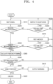
- FIG. 4 is a flowchart showing a method of controlling the lock control apparatus for a vehicle according to one embodiment of the present disclosure.
- the plurality of anchors 160 (161 to 167) installed in the vehicle 10 wait in the waiting mode to receive a signal transmitted from a corresponding terminal with respect to a pre-registered terminal 90 (S310).
- the anchor receiving the signal transmits data for signal reception to the processor 110 using CAN communication through the communication module 170.
- the processor 110 When the processor 110 does not receive a signal from the anchor for a first set time (n) or longer (S330), that is, when the anchor does not receive a signal of the terminal 90 for the first set time or more, the processor 110 switches the modes of the plurality of anchors to the sleep mode (S340).
- the processor 110 controls the first anchor 161 to maintain the waiting mode when receiving a signal from the first anchor 161 at the second time, and controls the fourth anchor 164 to enter the sleep mode when not receiving a signal from the fourth anchor 164 until the n th time has elapsed from the first time.
- the first anchor 161 maintains the waiting state, and the fourth anchor 164 enters the sleep mode and does not receive the signal.
- the processor 110 also switches the mode of the first anchor 161 to the sleep mode.
- the processor 110 counts the number of anchors receiving the signal, and determines whether the number of anchors receiving the signal is greater than or equal to a set number (S350).
- the processor 110 receives the signal of the terminal 90 and counts the number of anchors transmitting the signal to the processor 110.
- the processor 110 may also calculate a position of the terminal using one or two signals, but preferably calculate a position using at least three signals in order for a more accurate position.
- the accurate position can be calculated using at least three signals, three or more may be used for the set number.
- the set number may be changed in some cases.
- the processor 110 When the number of anchors receiving the signal is less than the set number, the processor 110 counts the time for which a state in which the number of anchors receiving the signal is less than the set number is maintained, and when the counted time is the second set time (m) or longer (S360), the processor 110 resets the plurality of anchors 161 to 167 to release the sleep mode and switches the modes of the plurality of anchors 161 to 167 to the waiting mode (S370).
- the processor 110 calculates a position of the terminal based on the received signal.
- the processor 110 calculates a position of the terminal 90 using the plurality of signals received from the anchors (S380).
- the processor 110 determines whether the detection signal is input from the detector 120 (S390).
- the processor 110 may receive a detection signal received from the touch sensor installed on the door. In addition, when the button installed on the door handle is operated, the processor 110 may receive a detection signal according to the button operation.
- the processor 110 When a door handle signal, that is, a signal from the sensor or the button, is not received, the processor 110 repeatedly calculates a position of the terminal 90 through the anchor, and tracks the position of the terminal 90 accordingly (S310 to S390).
- the processor 110 compares a position of the door at which the signal is received with the calculated position of the terminal 90 to determine whether the positions are the same (S400).
- the processor 110 outputs a warning (S410) and maintains the locked state.
- the processor 110 unlocks the door of the vehicle 10 (S420).
- the processor 110 may unlock only the same door as the position of the terminal according to settings. In addition, when the position of the door and the position of the terminal are the same, the processor 110 may unlock all of the plurality of doors.
- the processor 110 may unlock only the door at the position at which the signal of the door is received.
- the present invention is further defined by the following items.
Landscapes
- Engineering & Computer Science (AREA)
- Mechanical Engineering (AREA)
- Computer Networks & Wireless Communication (AREA)
- Physics & Mathematics (AREA)
- General Physics & Mathematics (AREA)
- Signal Processing (AREA)
- Manufacturing & Machinery (AREA)
- Lock And Its Accessories (AREA)
Abstract
Description
- Exemplary embodiments of the present disclosure relate to a lock control apparatus for a vehicle and a method of controlling the same that switch an anchor to a sleep mode to reduce power consumption and, in order to transmit and receive a signal for unlocking a vehicle, resets the anchor to release the sleep mode, receives the signal, and unlocks the vehicle.
- Smart keys are introduced in Vehicles and configured to unlock doors according to a driver's approach.
- In a smart key system, when a driver with a smart key approaches his/her vehicle and approaches an immobilizer unit mounted in the vehicle, the immobilizer unit performs a process of authenticating whether a smart key of the driver is a valid key, and when the smart key is the valid key, the immobilizer unit operates as a smart key function.
- When the smart key function is operated in the vehicle to which the smart key system is applied, the driver having the valid smart key can access the vehicle without a manual operation and unlock a door or trunk of the vehicle, and start an engine for driving with only a simple touch without manually starting the engine.
- However, the smart key system can improve the user's convenience, but there is no method of distinguishing a person who has a smart key and approaches a vehicle from a legitimate user (driver), and there is a problem in that there is no means to restrict an outsider who approaches the vehicle to open a door even when the driver having the smart key unlocks the door.
- Accordingly, the method of operating a button of the smart key multiple times or registering and identifying a driver's portable terminal is performed, but there is a problem in that power consumption is high while waiting to receive a signal from the portable terminal and causes accidents such as battery discharge.
- Accordingly, there is a need for a method of easily detecting a driver's approach, blocking unnecessary external access, and reducing power consumption.
- (Patent Document 1)
Korean Patent No. 10-1479037 - Various embodiments are directed to providing a lock control apparatus for a vehicle and a method of controlling the same that switch an operation mode of the plurality of anchors installed in the vehicle to reduce power consumed by a plurality of anchors and receives a signal of a terminal through the anchors to easily control a lock of the vehicle.
- In addition, various embodiments are directed to providing a lock control apparatus for a vehicle and a method of controlling the same by which security performance is improved.
- In an embodiment, a lock control apparatus for a vehicle according to the present disclosure includes: a plurality of anchors configured to receive a signal transmitted from a terminal; a communication module configured to transmit and receive a signal using controller area network (CAN) communication; a detector installed on a door and configured to input a detection signal; and a processor configured to receive the signal of the terminal from at least one of the plurality of anchors through the communication module, calculate a position of the terminal based on the signal of the terminal, determine whether to unlock the door in response to the position of the terminal and the detection signal, and control an engine to start, wherein the processor controls the anchor to enter a sleep mode in response to waiting times of the plurality of anchors, and when a signal is received from at least one of the plurality of anchors, resets the plurality of anchors to release the sleep mode and controls the anchors to enter the waiting mode in response to the number of anchors transmitting the signal of the terminal.
- In an embodiment, among the plurality of anchors, the processor may control a first anchor to enter the sleep mode when a signal is not received from the first anchor for a first time or longer, and maintain a second anchor in the waiting mode when a signal is received from the second anchor.
- In an embodiment, the processor may reset the plurality of anchors to enter the waiting mode when a state in which the number of anchors transmitting the signal of the terminal is less than a set number is maintained for a second time or longer.
- In an embodiment, the processor may compare a position of the door at which the detection signal is input with the position of the terminal when the detection signal is input, and unlock a corresponding door when the positions matches each other, and maintain the door in the locked state when the positions do not match each other.
- In an embodiment, the plurality of anchors may operate with a first current in the waiting mode, and operate with a second current smaller than the first current in the sleep mode.
- In an embodiment, the plurality of anchors may be installed at a plurality of positions of the vehicle to transmit the signal of the terminal to the processor through the communication module when receiving the signal of the terminal and receive a ultra-wide band (UWB) signal of the terminal.
- In an embodiment, the detector may be a sensor or a button installed at a handle provided on each of a plurality of doors.
- In addition, a method of controlling a lock control apparatus for a vehicle according to the present disclosure includes: waiting, by a plurality of anchors installed in a vehicle, to receive a signal transmitted from a terminal; counting individual waiting times of the plurality of anchors; switching a mode of at least one of the plurality of anchors to a sleep mode in response to the waiting times of the plurality of anchors; and resetting the plurality of anchors and entering a waiting mode in response to the number of anchors transmitting the signal of the terminal when a signal is received from at least one of the plurality of anchors.
- In an embodiment, the method may further include calculating a position of the terminal based on the signal of the terminal when the signal of the terminal is received from the at least one of the plurality of anchors.
- In an embodiment, the method may further include: comparing a position of the door with the position of the terminal in response to a detection signal input from at least one of a plurality of doors; unlocking a corresponding door when the positions match each other as a comparison result; and maintaining the door in a locked state when the positions do not match each other.
- In an embodiment, the detection signal may be input from a sensor or a button installed on a handle provided on each of the plurality of doors.
- In an embodiment, the entering of the sleep mode may further include: among the plurality of anchors, switching a mode of an anchor in which the waiting time is a first set time or longer to the sleep mode; and maintaining a second anchor in the waiting mode when a signal is received from the second anchor.
- In an embodiment, the entering of the waiting mode may include resetting the plurality of anchors to enter the waiting mode when a state in which the number of anchors transmitting the signal of the terminal is less than a set number is maintained for a second set time or longer.
- According to one aspect, a lock control apparatus and for a vehicle and a method of controlling the same according to the present disclosure can switch a mode of an anchor for receiving a signal to the sleep mode so as to reduce power consumption and switch the mode according to situations so that the signal can be received, and thus it is possible to minimize power consumption by efficiently controlling the anchor, prevent the hacking of a smart key, and easily track the position of a terminal so that the performance of the anchor is improved.
- According to the present disclosure, it is possible to improve stability and improve security performance of a vehicle by controlling the lock of a door.
-
-
FIG. 1 is a block diagram schematically showing a configuration of a lock control apparatus for a vehicle according to one embodiment of the present disclosure. -
FIGS. 2A and2B are reference views for describing an operation of receiving, by an anchor, a signal of a terminal in the lock control apparatus inFIG. 1 . -
FIGS. 3A to 3C are reference views for describing ranging for receiving the signal of the terminal in the lock control apparatus inFIG. 1 . -
FIG. 4 is a flowchart showing a method of controlling the lock control apparatus for a vehicle according to one embodiment of the present disclosure. - As is traditional in the corresponding field, some exemplary embodiments may be illustrated in the drawings in terms of functional blocks, units, and/or modules. Those of ordinary skill in the art will appreciate that these block, units, and/or modules are physically implemented by electronic (or optical) circuits such as logic circuits, discrete components, processors, hard-wired circuits, memory elements, wiring connections, and the like. When the blocks, units, and/or modules are implemented by processors or similar hardware, they may be programmed and controlled using software (e.g., code) to perform various functions discussed herein. Alternatively, each block, unit, and/or module may be implemented by dedicated hardware or as a combination of dedicated hardware to perform some functions and a processor (e.g., one or more programmed processors and associated circuitry) to perform other functions. Each block, unit, and/or module of some exemplary embodiments may be physically separated into two or more interacting and discrete blocks, units, and/or modules without departing from the scope of the inventive concept. Further, blocks, units, and/or module of some exemplary embodiments may be physically combined into more complex blocks, units, and/or modules without departing from the scope of the inventive concept.
- Hereinafter, the present disclosure will be described with reference to the accompanying drawings.
- In this process, the thicknesses of lines or the sizes of components shown in the drawings may be exaggerated for clarity and convenience of description. In addition, terms to be described below are terms defined in consideration of functions in the present disclosure, which may vary depending on the intention or custom of a user or an operator. Accordingly, these terms should be defined based on the contents throughout this specification.
-
FIG. 1 is a block diagram schematically showing a configuration of a lock control apparatus for a vehicle according to one embodiment of the present disclosure. - As shown in
FIG. 1 , avehicle 10 includes a plurality ofanchors 160, acommunication module 170, adetector 120, adoor driver 130, adata memory 140, adisplay 150, and aprocessor 110 for controlling overall operations. - The
vehicle 10 may be an electric vehicle or a hybrid electric vehicle that travels using a motor driven using a charged power of a battery and may be equally applied to an internal combustion engine vehicle operated by an engine. - The plurality of
anchors 160 are devices for communication with aterminal 90 and receive a signal transmitted from theterminal 90. - The plurality of
anchors 160 receive the signal transmitted from theterminal 90 that is an initiator (ultra-wide band (UWB) Initiator). Theterminal 90 is preferably registered in advance. - In this case, the
terminal 90 is a device set as the initiator and registered in advance and may use a fixed object (FOB) or a mobile communication terminal. In addition, theterminal 90 may include a smart key. - The plurality of
anchors 160 and theterminal 90 wirelessly communicate with each other in a UWB method. - The UWB is a wireless communication method that uses a signal with the bandwidth of 500 MHz or higher in a frequency band of 6 to 8 GHz and is a technique for calculating a distance between communication subjects by multiplying a signal arrival time between the communication subjects by the speed of light using a time of flight (ToF) technique.
- The plurality of
anchors 160 include first to seventh anchors. - The plurality of
anchors 160 are installed at a plurality of positions in thevehicle 10 to receive a signal of theterminal 90 and transmit the received signal to theprocessor 110 through thecommunication module 170. - The
communication module 170 transmits or receives data in the vehicle using controller area network (CAN) communication. - The
communication module 170 may include a module for wireless communication other than CAN communication to receive traffic information or the like from the outside. - The
detector 120 includes a plurality of sensors installed in the vehicle. Thedetector 120 includes a temperature sensor, a door sensor, a seating sensor, a distance sensor, etc. In addition, thedetector 120 includes a button installed on a door handle. - In addition, the
detector 120 further includes a proximity sensor (not shown) for detecting an object approaching the vehicle within a certain distance, and a touch sensor installed on the door handle to detect a touch. - The proximity sensor is installed on each of the plurality of doors to detect the object approaching within the certain distance, and the touch sensor receives a detection signal by detecting a case of gripping the door handle and inputs the detection signal to the processor. When the button on the door handle is operated, a detection signal may be input to the processor like the touch sensor.
- The
door driver 130 locks the door and unlocks the door according to a switch or button operation. - In addition, the
door driver 130 locks or unlocks the door in response to the detection signal of thedetector 120 and a control command of theprocessor 110. Thedoor driver 130 may control opening or closing of windows installed on the door. - The
data memory 140 stores control data for controlling operations of the vehicle, reference data for determining an operating state, traveling data for controlling traveling, and the like. Thedata memory 140 stores sensor data detected through thedetector 120 and data that is transmitted or received through thecommunication module 170. - The
display 150 includes at least one display and a plurality of lamps and displays the operating state of the vehicle, whether there is an abnormality, and the like. Thedisplay 150 may include a front navigation display, a head-up display (HUD), etc. - The
processor 110 controls the traveling of the vehicle according to a traveling algorithm of an autonomous traveling system as well as a steering device (not shown) and a brake system (not shown) operating by the driver. Theprocessor 110 controls the brake system so that a brake is automatically set when the vehicle is parked or stopped. - The
processor 110 locks or unlocks the vehicle after a position of the terminal is determined in response to signals received from the plurality ofanchors 160. Theprocessor 110 may unlock any one door or may simultaneously control a plurality of doors. - In addition, the
processor 110 may control an engine to start based on the signals received from the plurality ofanchors 160. Theprocessor 110 controls the engine to start when the terminal is positioned inside the vehicle. - The
processor 110 may unlock the vehicle in response to the signals received from the plurality ofanchors 160 and the detection signal of thedetector 120. - In addition, the
processor 110 may analyze the signals received from the plurality ofanchors 160, calculate the position of the terminal 90, and track a change in position. - When the
processor 110 receives signals from at least three anchors, theprocessor 110 calculates a distance between positions of the terminal 90 and the vehicle based on a triangulation method using corresponding signals. Theprocessor 110 may calculate the position of the terminal using one or two signals. However, since a more accurate position can be calculated using three or more signals are used, it is preferable that the processor calculates the position of the terminal using three or more signals. - The
processor 110 may stop waiting states of some anchors by switching the modes of some anchors to a sleep mode according to the number of anchors receiving a signal for a first set time among the plurality ofanchors 160. - In addition, the
processor 110 may switch the mode of the anchor to the waiting mode by resetting the anchor entered in the sleep mode to release the sleep mode. - Accordingly, the
vehicle 10 may identify the position of the terminal 90 through the plurality ofanchors 160 and compare the position of the terminal 90 with the location of the door according to the detection signal of thedetector 120 to unlock the door at a designated position. - In addition, the
vehicle 10 maintains the locked state when the position of the terminal 90 and the position of the door according to the detection signal are different. Meanwhile, when the terminal is positioned inside the vehicle, thevehicle 10 controls an engine to start based on the signal of the anchor. -
FIG. 2 is a reference view for describing an operation of receiving, by an anchor, a signal of a terminal in the lock control apparatus inFIG. 1 . - As shown in
FIG. 2A , the plurality of anchors 160 (161 to 167) are installed in thevehicle 10. - The plurality of
anchors 160 receive a signal transmitted from the terminal 90 through UWB communication to transmit the received signal to theprocessor 110. Each of the plurality ofanchors 161 to 167 is connected to a CAN communication line N of thecommunication module 170 to transmit the signal to theprocessor 110. - The plurality of
anchors 160 receive the signal transmitted from the terminal 90 while operating in the waiting mode, and the number of anchors receiving the signal varies depending on the position of the terminal 90 and the position of the anchor. - When the terminal 90 is positioned adjacent to a driver seat at the left of the
vehicle 10, afirst anchor 161, afourth anchor 164, afifth anchor 165, and aseventh anchor 167 receive the signal of the terminal 90. - Meanwhile, a
second anchor 162, athird anchor 163, and asixth anchor 166 do not receive the signal because thevehicle 10 or objects inside the vehicle function as obstacles. - In addition, as shown in
FIG. 2B , when the terminal 90 is positioned adjacent to a passenger seat at the right of thevehicle 10, thesecond anchor 162, thethird anchor 163, thefifth anchor 165, and thesixth anchor 166 may receive the signal. - When the
processor 110 receives the signal from at least one anchor, theprocessor 110 calculates the position of the terminal 90 in response to the received signal. - In addition, the
processor 110 finds the anchor receiving the signal and controls the anchor to enter the sleep mode in response to the number of the anchors receiving the signal, a waiting time, or the like or switches the mode of the anchor in a signal waiting state to the waiting mode by resetting the anchor in the sleep mode. - As shown in
FIG. 2A , thefirst anchor 161, thefourth anchor 164, thefifth anchor 165, and theseventh anchor 167 receive the signal of the terminal 90 at a first time to transmit the signal to theprocessor 110. - Meanwhile, the
second anchor 162, thethird anchor 163, and thesixth anchor 166 do not receive the signal of the terminal 90 and maintain the waiting mode for receiving a signal of the terminal. - The
second anchor 162, thethird anchor 163, and thesixth anchor 166 wait until receiving a signal of the terminal. When theanchor 160 waits for a long time, that is, the waiting time has elapsed for a first set time or longer, power consumption increases. - The
processor 110 switches the mode of a corresponding anchor to the sleep mode when a state in which a signal is not received from the anchor is maintained for the first set time or longer. - The sleep mode is a mode in which the anchor operates in a power saving state in a ranging state in which the anchor waits to receive the signal of the terminal.
- Meanwhile, when the terminal 90 is positioned at the same position as in
FIG. 2B in a state in which thesecond anchor 162, thethird anchor 163, and thesixth anchor 166 have entered to the sleep mode, thesecond anchor 162, thethird anchor 163, and thesixth anchor 166 may not receive the signal due to a state in the sleep mode even in receivable positions. - Accordingly, the
processor 110 resets the plurality ofanchors 160 to enter the waiting mode when the state in which the number of anchors receiving the signal is less than a set number is maintained for a second set time (m). - When the
fifth anchor 165 receives a signal and transmits the signal to theprocessor 110, theprocessor 110 may not identify an accurate position of the terminal, but may identify a direction of the terminal, and reset the plurality of anchors by determining that the terminal is positioned adjacent to the vehicle by a certain distance. - The
processor 110 resets the plurality of anchors, and thus thesecond anchor 162, thethird anchor 163, and thesixth anchor 166 enters the waiting mode to receive a signal of the terminal 90. - The
processor 110 calculates a position of the terminal 90 based on the signals received from thesecond anchor 162, thethird anchor 163, thefifth anchor 165, and thesixth anchor 166, and transmits the control command to thedoor driver 130 in response to the detection signal received from thedetector 120. - Accordingly, the
door driver 130 may control the door of the passenger seat to be unlocked. - Meanwhile, when a detection signal according to a handle touch is input from a door of a driver's rear seat in a state in which the terminal 90 is determined to be positioned adjacent to the passenger seat based on signals received from the
second anchor 162, thethird anchor 163, thefifth anchor 165, and thesixth anchor 166, theprocessor 110 maintains the locked state because the position of the terminal and a position at which the door attempts to be opened are different. - When the mode is set to open the door, the
processor 110 may unlock the plurality of doors in response to the detection signal and the signal of the terminal. - In addition, the
processor 110 determines a position of the terminal 90 based on the signals received from the plurality ofanchors 160 and controls an engine of the vehicle to start when the terminal is positioned inside the vehicle. -
FIG. 3 is a reference view for describing ranging for receiving the signal of the terminal in the lock control apparatus inFIG. 1 . - As shown in
FIG. 3A , the plurality ofanchors 160 maintain a waiting state to receive a signal of the terminal 90. - A signal of the terminal is generated at a certain period, and the signal is received once per block, and the signal is transmitted for each block at certain time intervals.
- Accordingly, the anchor waits to receive a signal transmitted from the terminal 90 to a
first block 11 and second to eighth blocks. - When the
first block 11 is in a range from a 0th time to to a first time t1, each of the second to eighth blocks may maintain the waiting state at the second to seventh times t2 to t7 that have the same time interval. - One block may be composed of about 192 ms, and one round may be divided into 1 to 24 ms, but may be changed according to settings.
- As shown in
FIG. 3B , one block, for example, thefirst block 11 is composed of first toeighth rounds 21 to 28. - The signal of the terminal 90 may be received during one round.
- In this case, a second current I02 is applied to the anchor while the anchor receives the signal, and the anchor maintains a first current I01 after receiving the signal. For example, the first current I01 is about 25 mA, and the second current I02 is about 100 mA.
- Since the signal is received once in the
first block 11, a corresponding anchor has the first current I01 after the signal is received in thefirst round 21. - Meanwhile, as shown in
FIG. 3C , when the signal is not received in thefirst round 21, the anchor maintains a waiting state in order of asecond round 22 and athird round 23. In this case, a current of the anchor while waiting becomes the second current I02. - Accordingly, when the waiting state continues for the first set time or longer, the power consumption of the anchor increases, and when a plurality of anchors maintain the waiting state, power consumption may increase in proportion to the number of anchors.
- The
processor 110 controls the anchor not receiving the signal to enter the sleep mode after waiting for the first set time. - In addition, when the number of anchors receiving the signal is a certain number or less and maintained for the second set time according to the number of anchors receiving the signal, the
processor 110 resets the plurality of anchors to enter the waiting mode. - For example, since at least three signals are required to track a position of the terminal 90, the
processor 110 may reset the plurality of anchors when a state in which the number of anchors receiving the signal is less than 3 is maintained for the second set time or longer. - The
processor 110 may calculate a position of the terminal using one or two signals even when signals are received from less than three anchors. However, since a more accurate position may be calculated when three or more signals are used, the reset of the anchor may be determined based on the three signals. - When a state in which the number of anchors receiving the signal is zero is maintained for the first set time or longer, all anchors enter the sleep mode.
- In this case, when all anchors enter the sleep mode, the
processor 110 may reset the plurality of anchors to enter the waiting mode periodically in a unit of a designated time because the anchor may not receive a signal of the terminal even when the terminal transmits the signal. -
FIG. 4 is a flowchart showing a method of controlling the lock control apparatus for a vehicle according to one embodiment of the present disclosure. - As shown in
FIG. 4 , the plurality of anchors 160 (161 to 167) installed in thevehicle 10 wait in the waiting mode to receive a signal transmitted from a corresponding terminal with respect to a pre-registered terminal 90 (S310). - When a certain anchor among the plurality of anchors receives a signal from the terminal 90 or the smart key (S320), the anchor receiving the signal transmits data for signal reception to the
processor 110 using CAN communication through thecommunication module 170. - When the
processor 110 does not receive a signal from the anchor for a first set time (n) or longer (S330), that is, when the anchor does not receive a signal of the terminal 90 for the first set time or more, theprocessor 110 switches the modes of the plurality of anchors to the sleep mode (S340). - For example, in a state in which the
first anchor 161 and thefourth anchor 164 receive a signal at the first time and transmit the received signal to theprocessor 110, theprocessor 110 controls thefirst anchor 161 to maintain the waiting mode when receiving a signal from thefirst anchor 161 at the second time, and controls thefourth anchor 164 to enter the sleep mode when not receiving a signal from thefourth anchor 164 until the nth time has elapsed from the first time. - Accordingly, the
first anchor 161 maintains the waiting state, and thefourth anchor 164 enters the sleep mode and does not receive the signal. When the signal is not received from thefirst anchor 161 until the nth time has elapsed from the second time, theprocessor 110 also switches the mode of thefirst anchor 161 to the sleep mode. - Meanwhile, when a signal is received from at least one anchor, the
processor 110 counts the number of anchors receiving the signal, and determines whether the number of anchors receiving the signal is greater than or equal to a set number (S350). - In other words, the
processor 110 receives the signal of the terminal 90 and counts the number of anchors transmitting the signal to theprocessor 110. Theprocessor 110 may also calculate a position of the terminal using one or two signals, but preferably calculate a position using at least three signals in order for a more accurate position. - Accordingly, since the accurate position can be calculated using at least three signals, three or more may be used for the set number. The set number may be changed in some cases.
- When the number of anchors receiving the signal is less than the set number, the
processor 110 counts the time for which a state in which the number of anchors receiving the signal is less than the set number is maintained, and when the counted time is the second set time (m) or longer (S360), theprocessor 110 resets the plurality ofanchors 161 to 167 to release the sleep mode and switches the modes of the plurality ofanchors 161 to 167 to the waiting mode (S370). - When the number of anchors is less than the set number, the
processor 110 calculates a position of the terminal based on the received signal. - When the number of anchors receiving the signal is greater than or equal to the set number, the
processor 110 calculates a position of the terminal 90 using the plurality of signals received from the anchors (S380). - In addition, the
processor 110 determines whether the detection signal is input from the detector 120 (S390). - The
processor 110 may receive a detection signal received from the touch sensor installed on the door. In addition, when the button installed on the door handle is operated, theprocessor 110 may receive a detection signal according to the button operation. - When a door handle signal, that is, a signal from the sensor or the button, is not received, the
processor 110 repeatedly calculates a position of the terminal 90 through the anchor, and tracks the position of the terminal 90 accordingly (S310 to S390). - When a signal according to the sensor or button operation of the door handle is received, the
processor 110 compares a position of the door at which the signal is received with the calculated position of the terminal 90 to determine whether the positions are the same (S400). - Meanwhile, when the position of the door at which the signal is received and the position of the terminal 90 are different, the
processor 110 outputs a warning (S410) and maintains the locked state. - When the position of the door at which the signal is received and the position of the terminal 90 are the same, the
processor 110 unlocks the door of the vehicle 10 (S420). - When the position of the door and the position of the terminal are the same, the
processor 110 may unlock only the same door as the position of the terminal according to settings. In addition, when the position of the door and the position of the terminal are the same, theprocessor 110 may unlock all of the plurality of doors. - In addition, when the position of the terminal is the same as the position at which the signals of the plurality of doors are received in a state in which the signals are received from the plurality of doors, the
processor 110 may unlock only the door at the position at which the signal of the door is received. - The present invention is further defined by the following items.
- 1. A lock control apparatus for a vehicle, comprising:
- a plurality of anchors configured to receive a signal transmitted from a terminal;
- a communication module configured to transmit and receive a signal using controller area network (CAN) communication;
- a detector installed on a door and configured to input a detection signal; and
- a processor configured to receive the signal of the terminal from at least one of the plurality of anchors through the communication module, calculate a position of the terminal based on the signal of the terminal, determine whether to unlock the door in response to the position of the terminal and the detection signal, and control an engine to start,
- wherein the processor controls the plurality of anchors to enter a sleep mode in response to waiting times of the plurality of anchors, and
- when a signal is received from at least one of the plurality of anchors, resets the plurality of anchors to release the sleep mode and controls the anchors to enter a waiting mode in response to the number of anchors transmitting the signal of the terminal.
- 2. The lock control apparatus of
item 1, wherein, among the plurality of anchors, the processor controls a first anchor to enter the sleep mode when a signal is not received from the first anchor for a first time or longer, and maintains a second anchor in the waiting mode when a signal is received from the second anchor. - 3. The lock control apparatus of
item - 4. The lock control apparatus of
item - 5. The lock control apparatus of any one of
items 1 to 4, wherein the processor calculates a position of the terminal based on at least three signals received from the plurality of anchors, and tracks movement of the terminal. - 6. The lock control apparatus of any one of
items 1 to 5, wherein the processor compares a position of the door at which the detection signal is input with the position of the terminal when the detection signal is input, and unlocks a corresponding door when the positions matches each other, and maintains the door in the locked state when the positions do not match each other. - 7. The lock control apparatus of any one of
items 1 to 6, wherein the plurality of anchors:- receive the signal of the terminal periodically in a unit of a first time,
- terminate waiting when the signal of the terminal is received in a nth round within the first time, and wait again after a next first time, and
- maintain the waiting state when the signal of the terminal is not received within the first time, and enter the sleep mode by the processor when the signal of the terminal is not received for a first set time.
- 8. The lock control apparatus of any one of
items 1 to 7, wherein the plurality of anchors operate with a first current in the waiting mode, and operate with a second current smaller than the first current in the sleep mode. - 9. The lock control apparatus of any one of
items 1 to 8, wherein the plurality of anchors are installed at a plurality of positions of the vehicle to transmit the signal of the terminal to the processor through the communication module when receiving the signal of the terminal and receive a ultra-wide band (UWB) signal of the terminal. - 10. A method of controlling a lock control apparatus for a vehicle, the method comprising:
- waiting, by a plurality of anchors installed in a vehicle, to receive a signal transmitted from a terminal;
- counting individual waiting times of the plurality of anchors;
- switching a mode of at least one of the plurality of anchors to a sleep mode in response to the waiting times of the plurality of anchors; and
- resetting the plurality of anchors and entering a waiting mode in response to the number of anchors transmitting the signal of the terminal when a signal is received from at least one of the plurality of anchors.
- 11. The method of
item 10, further comprising calculating a position of the terminal based on the signal of the terminal when the signal of the terminal is received from the at least one of the plurality of anchors. - 12. The method of
item 11, further comprising:- comparing a position of the door with the position of the terminal in response to a detection signal input from at least one of a plurality of doors;
- unlocking a corresponding door when the positions match each other as a comparison result; and
- maintaining the door in a locked state when the positions do not match each other.
- 13. The method of item 12, wherein the detection signal is input from a sensor or a button installed on a handle provided on each of the plurality of doors.
- 14. The method of any one of
items 10 to 13, wherein the entering of the sleep mode further includes:- among the plurality of anchors, switching a mode of an anchor in which the waiting time is a first set time or longer to the sleep mode; and
- maintaining a second anchor in the waiting mode when a signal is received from the second anchor.
- 15. The method of any one of
items 10 to 14, wherein the entering of the waiting mode includes resetting the plurality of anchors to enter the waiting mode when a state in which the number of anchors transmitting the signal of the terminal is less than a set number is maintained for a second set time or longer.
Claims (6)
- A method of ranging for receiving a signal in an anchor,waiting for a signal from an initiator, wherein the signal is generated for each block at a period;ranging an anchor between the initiator and the anchor based on a ranging block, wherein the ranging block is divided into ranging rounds; anddetermining whether or not the signal is received based on a time grid for a ranging session for the ranging block.
- The method of claim 1, wherein the anchor is connected to the initiator based on the time grid.
- The method of claim 1,wherein a state for the anchor is determined based on the time grid, andwherein the state includes a sleep mode and a waiting mode.
- A device of ranging for receiving a signal in an anchor,a processor (110); anda memory configured to store control data for controlling the processor,wherein the processor (110) is configured to:wait for a signal from an initiator, wherein the signal is generated for each block at a period; andrange an anchor between the initiator and the anchor based on a ranging block, wherein the ranging block is divided into ranging rounds, anddetermine whether or not the signal is received based on a time grid for a ranging session for the ranging block.
- The device of claim 4, wherein the anchor is connected to the initiator based on the time grid.
- The device of claim 4.wherein a state for the anchor is determined based on the time grid, andwherein the state includes a sleep mode and a waiting mode.
Priority Applications (1)
| Application Number | Priority Date | Filing Date | Title |
|---|---|---|---|
| EP26152559.6A EP4722758A2 (en) | 2021-10-13 | 2022-07-11 | Lock control apparatus for vehicle and method of controlling the same |
Applications Claiming Priority (2)
| Application Number | Priority Date | Filing Date | Title |
|---|---|---|---|
| KR1020210135585A KR20230052475A (en) | 2021-10-13 | 2021-10-13 | Safety unlock controlling apparatus and method for vehicle |
| EP22184177.8A EP4167203B1 (en) | 2021-10-13 | 2022-07-11 | Lock control apparatus for vehicle and method of controlling the same |
Related Parent Applications (2)
| Application Number | Title | Priority Date | Filing Date |
|---|---|---|---|
| EP22184177.8A Division-Into EP4167203B1 (en) | 2021-10-13 | 2022-07-11 | Lock control apparatus for vehicle and method of controlling the same |
| EP22184177.8A Division EP4167203B1 (en) | 2021-10-13 | 2022-07-11 | Lock control apparatus for vehicle and method of controlling the same |
Related Child Applications (1)
| Application Number | Title | Priority Date | Filing Date |
|---|---|---|---|
| EP26152559.6A Division EP4722758A2 (en) | 2021-10-13 | 2022-07-11 | Lock control apparatus for vehicle and method of controlling the same |
Publications (3)
| Publication Number | Publication Date |
|---|---|
| EP4224445A2 true EP4224445A2 (en) | 2023-08-09 |
| EP4224445A3 EP4224445A3 (en) | 2023-08-23 |
| EP4224445B1 EP4224445B1 (en) | 2026-02-04 |
Family
ID=83228651
Family Applications (3)
| Application Number | Title | Priority Date | Filing Date |
|---|---|---|---|
| EP22184177.8A Active EP4167203B1 (en) | 2021-10-13 | 2022-07-11 | Lock control apparatus for vehicle and method of controlling the same |
| EP23165176.1A Active EP4224445B1 (en) | 2021-10-13 | 2022-07-11 | Lock control apparatus for vehicle and method of controlling the same |
| EP26152559.6A Pending EP4722758A2 (en) | 2021-10-13 | 2022-07-11 | Lock control apparatus for vehicle and method of controlling the same |
Family Applications Before (1)
| Application Number | Title | Priority Date | Filing Date |
|---|---|---|---|
| EP22184177.8A Active EP4167203B1 (en) | 2021-10-13 | 2022-07-11 | Lock control apparatus for vehicle and method of controlling the same |
Family Applications After (1)
| Application Number | Title | Priority Date | Filing Date |
|---|---|---|---|
| EP26152559.6A Pending EP4722758A2 (en) | 2021-10-13 | 2022-07-11 | Lock control apparatus for vehicle and method of controlling the same |
Country Status (4)
| Country | Link |
|---|---|
| US (4) | US12017611B2 (en) |
| EP (3) | EP4167203B1 (en) |
| KR (2) | KR20230052475A (en) |
| CN (2) | CN115959084A (en) |
Families Citing this family (2)
| Publication number | Priority date | Publication date | Assignee | Title |
|---|---|---|---|---|
| KR20230052475A (en) | 2021-10-13 | 2023-04-20 | 현대모비스 주식회사 | Safety unlock controlling apparatus and method for vehicle |
| CN117037337B (en) * | 2023-08-29 | 2026-01-23 | 深蓝汽车科技有限公司 | Vehicle unlocking method, device, equipment and system |
Citations (1)
| Publication number | Priority date | Publication date | Assignee | Title |
|---|---|---|---|---|
| KR101479037B1 (en) | 2014-01-29 | 2015-01-05 | 주식회사 유라코퍼레이션 | Smart key system and method searching smart key thereof |
Family Cites Families (16)
| Publication number | Priority date | Publication date | Assignee | Title |
|---|---|---|---|---|
| US5887176A (en) * | 1996-06-28 | 1999-03-23 | Randtec, Inc. | Method and system for remote monitoring and tracking of inventory |
| US7031665B1 (en) | 1999-04-12 | 2006-04-18 | Anders Trell Trust | Method and device for utilization of mobile radio telephones for surveillance and/or control purposes |
| JP6212973B2 (en) * | 2013-06-19 | 2017-10-18 | 株式会社デンソー | Portable device search device, portable device search method, portable device search program |
| CN103605109B (en) * | 2013-12-02 | 2016-02-17 | 山东工商学院 | Mine underground accurate positioning system and positioning method based on linear frequency modulation signals |
| JP6520283B2 (en) * | 2015-03-25 | 2019-05-29 | 株式会社デンソー | User identification system, portable device for vehicle |
| US10328899B2 (en) * | 2016-10-12 | 2019-06-25 | Denso International America, Inc. | Localization and passive entry / passive start systems and methods for vehicles |
| US10716068B2 (en) * | 2017-10-13 | 2020-07-14 | Denso International America, Inc. | Power saving methods for communication in localization systems |
| KR102878864B1 (en) * | 2018-10-26 | 2025-10-31 | 삼성전자주식회사 | A method and apparatus for scheduling using alternative signals in a wireless communication system |
| EP3670275A1 (en) * | 2018-12-21 | 2020-06-24 | Nxp B.V. | Rf system and method for implementing role switching of transceiver nodes |
| EP3940419A4 (en) * | 2019-05-14 | 2022-06-01 | Samsung Electronics Co., Ltd. | ELECTRONIC DEVICE FOR PERFORMING ULTRA-WIDEBAND TELEMETRY AND METHOD OF OPERATING ELECTRONIC DEVICE |
| KR102757986B1 (en) * | 2019-08-20 | 2025-01-22 | 현대모비스 주식회사 | Smart key system and method for detecting relay station attack using the system |
| KR102891018B1 (en) * | 2019-12-06 | 2025-11-24 | 삼성전자주식회사 | Electronic device and method for performing ranging through uwb |
| EP3836573A1 (en) * | 2019-12-09 | 2021-06-16 | Valeo Comfort and Driving Assistance | Method for locating an electronic device, corresponding system and corresponding electronic device |
| WO2021157967A1 (en) * | 2020-02-07 | 2021-08-12 | Samsung Electronics Co., Ltd. | Electronic device for performing ranging by using ultra wide band communication and operating method thereof |
| KR20230052475A (en) * | 2021-10-13 | 2023-04-20 | 현대모비스 주식회사 | Safety unlock controlling apparatus and method for vehicle |
| US12445996B2 (en) * | 2022-02-25 | 2025-10-14 | Qualcomm Incorporated | Distributed time synchronization for time difference of arrival (TDOA) using ultra-wideband (UWB) |
-
2021
- 2021-10-13 KR KR1020210135585A patent/KR20230052475A/en active Pending
-
2022
- 2022-07-11 EP EP22184177.8A patent/EP4167203B1/en active Active
- 2022-07-11 EP EP23165176.1A patent/EP4224445B1/en active Active
- 2022-07-11 EP EP26152559.6A patent/EP4722758A2/en active Pending
- 2022-08-04 CN CN202210935044.8A patent/CN115959084A/en active Pending
- 2022-08-04 CN CN202310445846.5A patent/CN116533927A/en active Pending
- 2022-08-22 US US17/892,631 patent/US12017611B2/en active Active
-
2023
- 2023-04-11 KR KR1020230047394A patent/KR20230052862A/en not_active Ceased
- 2023-04-18 US US18/136,000 patent/US12012072B2/en active Active
-
2024
- 2024-05-13 US US18/662,293 patent/US12311879B2/en active Active
-
2025
- 2025-04-30 US US19/195,708 patent/US20250256683A1/en active Pending
Patent Citations (1)
| Publication number | Priority date | Publication date | Assignee | Title |
|---|---|---|---|---|
| KR101479037B1 (en) | 2014-01-29 | 2015-01-05 | 주식회사 유라코퍼레이션 | Smart key system and method searching smart key thereof |
Also Published As
| Publication number | Publication date |
|---|---|
| US12017611B2 (en) | 2024-06-25 |
| EP4167203A1 (en) | 2023-04-19 |
| EP4167203B1 (en) | 2025-04-09 |
| EP4224445A3 (en) | 2023-08-23 |
| EP4224445B1 (en) | 2026-02-04 |
| US12311879B2 (en) | 2025-05-27 |
| EP4722758A2 (en) | 2026-04-08 |
| CN115959084A (en) | 2023-04-14 |
| US20250256683A1 (en) | 2025-08-14 |
| US20230249646A1 (en) | 2023-08-10 |
| KR20230052862A (en) | 2023-04-20 |
| CN116533927A (en) | 2023-08-04 |
| US20240294139A1 (en) | 2024-09-05 |
| KR20230052475A (en) | 2023-04-20 |
| US20230111997A1 (en) | 2023-04-13 |
| US12012072B2 (en) | 2024-06-18 |
Similar Documents
| Publication | Publication Date | Title |
|---|---|---|
| US20250256683A1 (en) | Lock control apparatus for vehicle and method of controlling the same | |
| US10513244B2 (en) | Vehicle control system and vehicle control device | |
| US10158719B2 (en) | Vehicle communication system | |
| JP6188707B2 (en) | Car access system | |
| US10212557B2 (en) | Position-based limited-response mode operation in a vehicle communication system | |
| JP3809934B2 (en) | Vehicle remote control system | |
| EP1916162B1 (en) | Passive keyless entry system | |
| JP6079577B2 (en) | Vehicle door control device | |
| JP4604984B2 (en) | In-vehicle device control system | |
| EP3003798B1 (en) | Movement pattern detection in a vehicle communication system | |
| US7868735B2 (en) | Vehicle door control system | |
| US10487546B2 (en) | Door locking device for vehicle | |
| CN110356361A (en) | Input Signal Management for Vehicle Parking Assist | |
| CN110356360A (en) | Input Signal Management for Vehicle Parking Assist | |
| CN109789850B (en) | Method for operating a central locking device, central locking device and motor vehicle | |
| JP2017040083A (en) | Motion operation device and motion operation method | |
| JP3724628B2 (en) | Vehicle door remote control system |
Legal Events
| Date | Code | Title | Description |
|---|---|---|---|
| PUAI | Public reference made under article 153(3) epc to a published international application that has entered the european phase |
Free format text: ORIGINAL CODE: 0009012 |
|
| STAA | Information on the status of an ep patent application or granted ep patent |
Free format text: STATUS: REQUEST FOR EXAMINATION WAS MADE |
|
| PUAL | Search report despatched |
Free format text: ORIGINAL CODE: 0009013 |
|
| 17P | Request for examination filed |
Effective date: 20230331 |
|
| AC | Divisional application: reference to earlier application |
Ref document number: 4167203 Country of ref document: EP Kind code of ref document: P |
|
| AK | Designated contracting states |
Kind code of ref document: A2 Designated state(s): AL AT BE BG CH CY CZ DE DK EE ES FI FR GB GR HR HU IE IS IT LI LT LU LV MC MK MT NL NO PL PT RO RS SE SI SK SM TR |
|
| AK | Designated contracting states |
Kind code of ref document: A3 Designated state(s): AL AT BE BG CH CY CZ DE DK EE ES FI FR GB GR HR HU IE IS IT LI LT LU LV MC MK MT NL NO PL PT RO RS SE SI SK SM TR |
|
| RIC1 | Information provided on ipc code assigned before grant |
Ipc: G01S 13/76 20060101ALI20230718BHEP Ipc: G07C 9/00 20200101AFI20230718BHEP |
|
| RBV | Designated contracting states (corrected) |
Designated state(s): AL AT BE BG CH CY CZ DE DK EE ES FI FR GB GR HR HU IE IS IT LI LT LU LV MC MK MT NL NO PL PT RO RS SE SI SK SM TR |
|
| STAA | Information on the status of an ep patent application or granted ep patent |
Free format text: STATUS: EXAMINATION IS IN PROGRESS |
|
| 17Q | First examination report despatched |
Effective date: 20240711 |
|
| GRAP | Despatch of communication of intention to grant a patent |
Free format text: ORIGINAL CODE: EPIDOSNIGR1 |
|
| STAA | Information on the status of an ep patent application or granted ep patent |
Free format text: STATUS: GRANT OF PATENT IS INTENDED |
|
| INTG | Intention to grant announced |
Effective date: 20250821 |
|
| GRAS | Grant fee paid |
Free format text: ORIGINAL CODE: EPIDOSNIGR3 |
|
| GRAA | (expected) grant |
Free format text: ORIGINAL CODE: 0009210 |
|
| STAA | Information on the status of an ep patent application or granted ep patent |
Free format text: STATUS: THE PATENT HAS BEEN GRANTED |
|
| AC | Divisional application: reference to earlier application |
Ref document number: 4167203 Country of ref document: EP Kind code of ref document: P |
|
| AK | Designated contracting states |
Kind code of ref document: B1 Designated state(s): AL AT BE BG CH CY CZ DE DK EE ES FI FR GB GR HR HU IE IS IT LI LT LU LV MC MK MT NL NO PL PT RO RS SE SI SK SM TR |
|
| P01 | Opt-out of the competence of the unified patent court (upc) registered |
Free format text: CASE NUMBER: UPC_APP_0019590_4224445/2025 Effective date: 20251229 |
|
| REG | Reference to a national code |
Ref country code: CH Ref legal event code: F10 Free format text: ST27 STATUS EVENT CODE: U-0-0-F10-F00 (AS PROVIDED BY THE NATIONAL OFFICE) Effective date: 20260204 Ref country code: GB Ref legal event code: FG4D |
|
| REG | Reference to a national code |
Ref country code: DE Ref legal event code: R096 Ref document number: 602022030002 Country of ref document: DE |
|
| REG | Reference to a national code |
Ref country code: IE Ref legal event code: FG4D |