EP4224390A1 - Information processing apparatus, information processing program, and information processing method - Google Patents
Information processing apparatus, information processing program, and information processing method Download PDFInfo
- Publication number
- EP4224390A1 EP4224390A1 EP22192300.6A EP22192300A EP4224390A1 EP 4224390 A1 EP4224390 A1 EP 4224390A1 EP 22192300 A EP22192300 A EP 22192300A EP 4224390 A1 EP4224390 A1 EP 4224390A1
- Authority
- EP
- European Patent Office
- Prior art keywords
- workflow
- information processing
- file
- steps
- folder
- Prior art date
- Legal status (The legal status is an assumption and is not a legal conclusion. Google has not performed a legal analysis and makes no representation as to the accuracy of the status listed.)
- Granted
Links
Images





Classifications
-
- G—PHYSICS
- G06—COMPUTING OR CALCULATING; COUNTING
- G06F—ELECTRIC DIGITAL DATA PROCESSING
- G06F16/00—Information retrieval; Database structures therefor; File system structures therefor
- G06F16/10—File systems; File servers
- G06F16/16—File or folder operations, e.g. details of user interfaces specifically adapted to file systems
- G06F16/168—Details of user interfaces specifically adapted to file systems, e.g. browsing and visualisation, 2d or 3d GUIs
-
- G—PHYSICS
- G06—COMPUTING OR CALCULATING; COUNTING
- G06Q—INFORMATION AND COMMUNICATION TECHNOLOGY [ICT] SPECIALLY ADAPTED FOR ADMINISTRATIVE, COMMERCIAL, FINANCIAL, MANAGERIAL OR SUPERVISORY PURPOSES; SYSTEMS OR METHODS SPECIALLY ADAPTED FOR ADMINISTRATIVE, COMMERCIAL, FINANCIAL, MANAGERIAL OR SUPERVISORY PURPOSES, NOT OTHERWISE PROVIDED FOR
- G06Q10/00—Administration; Management
- G06Q10/10—Office automation; Time management
- G06Q10/103—Workflow collaboration or project management
-
- G—PHYSICS
- G06—COMPUTING OR CALCULATING; COUNTING
- G06F—ELECTRIC DIGITAL DATA PROCESSING
- G06F3/00—Input arrangements for transferring data to be processed into a form capable of being handled by the computer; Output arrangements for transferring data from processing unit to output unit, e.g. interface arrangements
- G06F3/01—Input arrangements or combined input and output arrangements for interaction between user and computer
- G06F3/048—Interaction techniques based on graphical user interfaces [GUI]
- G06F3/0484—Interaction techniques based on graphical user interfaces [GUI] for the control of specific functions or operations, e.g. selecting or manipulating an object, an image or a displayed text element, setting a parameter value or selecting a range
- G06F3/04845—Interaction techniques based on graphical user interfaces [GUI] for the control of specific functions or operations, e.g. selecting or manipulating an object, an image or a displayed text element, setting a parameter value or selecting a range for image manipulation, e.g. dragging, rotation, expansion or change of colour
-
- G—PHYSICS
- G06—COMPUTING OR CALCULATING; COUNTING
- G06F—ELECTRIC DIGITAL DATA PROCESSING
- G06F3/00—Input arrangements for transferring data to be processed into a form capable of being handled by the computer; Output arrangements for transferring data from processing unit to output unit, e.g. interface arrangements
- G06F3/01—Input arrangements or combined input and output arrangements for interaction between user and computer
- G06F3/048—Interaction techniques based on graphical user interfaces [GUI]
- G06F3/0484—Interaction techniques based on graphical user interfaces [GUI] for the control of specific functions or operations, e.g. selecting or manipulating an object, an image or a displayed text element, setting a parameter value or selecting a range
- G06F3/0486—Drag-and-drop
Definitions
- the present disclosure relates to an information processing apparatus, an information processing program, and an information processing method
- Japanese Unexamined Patent Application Publication No. 2012-185838 discloses an electronic file system.
- the electronic file system displays preview information that represents a type of action to be taken.
- Japanese Unexamined Patent Application Publication No. 2021-027539 discloses an information processing apparatus.
- the information processing apparatus selects between a first mode and a second mode in response to an instruction from a user.
- the first mode is used to receive information on a selected workflow that processes target data before receiving the target data.
- the second mode is used to receive information on a selected workflow that processes target data after receiving the target data.
- Japanese Unexamined Patent Application Publication No. 2012-088912 discloses a technique of displaying a customized screen.
- an appropriate customized screen is set for each document according to a predetermined sorting condition of the registered documents.
- the customized screen is displayed.
- a workflow is set beforehand in a folder and is executed when a file is dragged and dropped onto the folder.
- execution of part of the workflow is not so easy.
- the execution of the workflow starting with an intermediate step or the execution of the workflow after editing the workflow is not so easy.
- a new workflow is to be produced in order to execute the workflow starting with the intermediate step or execute the workflow after editing.
- an information processing apparatus including a processor configured to: if a file serving as a process target is dragged to a folder where a workflow including multiple steps is set beforehand, display the steps included in the workflow set in the folder; and if the file is dropped onto a step of interest out of the displayed steps, perform a process of executing the workflow, starting with the step of interest.
- an information processing apparatus comprising a processor configured to: display both a folder where a workflow including a plurality of steps is set beforehand and the steps of the workflow set in the folder; edit the displayed workflow using a trajectory along which a file serving as a process target has been dragged; and if the file is dropped, perform a process that executes the edited workflow.
- the processor in the information processing apparatus is configured to, if the file is dragged to the step of interest, further display process contents of each of the steps of the workflow, starting with the step of interest.
- the processor in the information processing apparatus is configured to, if the file is dragged to the step of interest, further display execution result prediction of execution of the workflow starting with the step of interest.
- the processor in the information processing apparatus is configured to, if the file is dragged over the displayed execution result prediction and dropped onto a second workflow, execute the second workflow in succession to the workflow of the execution result prediction.
- the processor in the information processing apparatus is configured to, if an infeasible step is present, display the infeasible step in a display form indicative of infeasibility.
- the processor in the information processing apparatus is configured to select, out of the displayed steps, a step to be executed, by using a trajectory along which the file has been dragged.
- the processor in the information processing apparatus is configured to select, as an execution target out of the displayed steps, a step that has undergone a predetermined operation.
- the predetermined operation is to position the file on the step of interest until a predetermined time duration elapses with the file in a dragged state.
- the processor in the information processing apparatus is configured to further display a step that is enabled to be registered as a step of the workflow.
- an information processing program causing a computer to execute a process, the process including: if a file serving as a process target is dragged to a folder where a workflow including a plurality of steps is set beforehand, displaying the steps included in the workflow set in the folder; and if the file is dropped onto a step of interest out of the displayed steps, performing a process of executing the workflow, starting with the step of interest.
- an information processing method including: if a file serving as a process target is dragged to a folder where a workflow including a plurality of steps is set beforehand, displaying the steps included in the workflow set in the folder; and if the file is dropped onto a step of interest out of the displayed steps, performing a process of executing the workflow, starting with the step of interest.
- the information processing apparatus provided according to the first aspect may execute part of the workflow in response to a simpler operation than when a new workflow is produced.
- the information processing apparatus provided according to the second aspect may execute part of the workflow in response to a simpler operation when a new workflow is produced.
- process contents may be verified when the workflow is executed starting with an intermediate step.
- execution result prediction may be verified when the workflow is executed starting with the intermediate step.
- multiple workflows may be consecutively executed.
- an executable step may be recognized.
- a step that is to be performed in a more intuitive manner may be determined than when a keyboard or the like is operated.
- a step to be executed may be selected from a trajectory along which a file is dragged.
- a step to be executed may be selected without operating the keyboard or the like from the trajectory along which the file is dragged.
- a step to be executed in the workflow may be added.
- the information processing program provided according to the eleventh aspect may execute part of the workflow in a simpler operation than when a new workflow is produced.
- the information processing method provided according to the twelfth aspect may execute part of the workflow in a simpler operation than when a new workflow is produced.
- the exemplary embodiment is related to an information processing system 10 that includes multiple image forming apparatuses, multiple information processing terminals, and an information processing apparatus serving as a cloud server, interconnected to each other via a communication network.
- Fig. 1 illustrates the configuration of the information processing system 10 of the exemplary embodiment.
- the information processing system 10 of the exemplary embodiment includes image forming apparatuses 12a, 12b, ..., information processing terminals 14a, 14b, ..., and cloud server 16. If the image forming apparatuses 12a, 12b, ... are not differentiated from each other, each image forming apparatus is collectively referred to as an image forming apparatus 12. If the information processing terminals 14a, 14b, ... are not differentiated from each other, each information processing terminal is collectively referred to as an information processing terminal 14. In the discussion of the exemplary embodiment, the image forming apparatuses 12a, 12b, ..., and the information processing terminals 14a, 14b, ... are employed. The number of image forming apparatuses 12 may be one or more, and the number of information processing terminals 14 may be one or more.
- the image forming apparatus 12, information processing terminal 14, and cloud server 16 are interconnected to each other via the communication network 18 including a local-area network (LAN), wide-area network (WAN), Internet, and/or intranet.
- the image forming apparatus 12, information processing terminal 14, and cloud server 16 may exchange a variety of data with each other via the communication network 18.
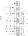
- Fig. 2 is a block diagram illustrating an electrical configuration of a major portion of the image forming apparatus 12 of the exemplary embodiment.
- the image forming apparatus 12 of the exemplary embodiment includes a control unit 20 including a central processing unit (CPU) 20A, read-only memory (ROM) 20B, random-access memory (RAM) 20C as illustrated in Fig. 3 .
- the CPU 20A controls the entire operation of the image forming apparatus 12.
- the RAM 20C is used as a work area when the CPU 20A executes a variety of programs.
- the ROM 20B stores beforehand a variety of control programs and a variety of parameters.
- Each section of the control unit 20 is electrically connected to elements of the image forming apparatus 12 via a system bus 42.
- the image forming apparatus 12 of the exemplary embodiment includes a hard disk drive (HDD) 26 that stores a variety of data and a variety of application programs.
- the image forming apparatus 12 further includes a display controller 28 that is connected to a user interface 22 and controls displaying of a variety of operation screens onto the user interface 22.
- the image forming apparatus 12 further includes an operation input detector 30 that is connected to the user interface 22 and detects an operation instruction that is received via the user interface 22.
- the HDD 26, display controller 28, and operation input detector 30 are electrically connected to the system bus 42.
- the image forming apparatus 12 of the exemplary embodiment includes the HDD 26 as a memory.
- the image forming apparatus 12 may include a non-volatile memory, such as a flash memory.
- the image forming apparatus 12 includes a reading controller 32 and image formation controller 34.
- the reading controller 32 controls a reading operation that a document reader 44 performs to optically read an image and also controls a document transport operation that a document transporter performs.
- the image formation controller 34 controls an image forming operation performed by an image former 24 and paper transportation that the transporter 25 performs to transport paper sheet to the image former 24.
- the image forming apparatus 12 further includes a communication network interface (I/F) 36 that is connected to the communication network 18 and transmits or receives communication data to or from an external apparatus, such as the cloud server 16 connected to the communication network 18.
- I/F communication network interface
- the image forming apparatus 12 further includes a facsimile I/F 38 that is connected to a telephone network (not illustrated) and transmits or receives facsimile data to or from a facsimile machine via the telephone network.
- the image forming apparatus 12 further includes a transmit-receive controller 40 that transmits or receives facsimile data via the facsimile I/F 38.
- the transmit-receive controller 40, reading controller 32, image formation controller 34, communication network I/F 36, facsimile I/F 38, and log collector 46 are electrically connected to the system bus 42.
- the CPU 20A in the image forming apparatus 12 of the exemplary embodiment accesses each of the RAM 20C, ROM 20B, and HDD 26.
- the CPU 20A in the image forming apparatus 12 controls displaying of an operation screen and information including a variety of messages on a display 22A of the user interface 22.
- the CPU 20A in the image forming apparatus 12 controls the operation of the document reader 44 and document transporter.
- the image formation controller 34 the CPU 20A in the image forming apparatus 12 controls the operation of the image former 24 and transporter 25 and transmission and reception of communication data via the communication network I/F 36.
- the CPU 20A in the image forming apparatus 12 controls the transmission and reception of facsimile data via the facsimile I/F 38.
- the CPU 20A in the image forming apparatus 12 recognizes contents of operation of the user interface 22 in accordance with operation information detected by the operation input detector 30 and performs various control operations responsive to the contents of operation.
- FIG. 3 is a block diagram illustrating the electrical configuration of the major portion of the information processing terminal 14 and cloud server 16.
- Each of the information processing terminal 14 and cloud server 16 has a typical computer configuration. Only the cloud server 16 is representatively described herein.
- the cloud server 16 of the exemplary embodiment includes a CPU 16A, ROM 16B, RAM 16C, HDD 16D, operation unit 16E, display 16F, and communication network interface (I/F) 16G.
- the CPU 16A controls the whole operation of the cloud server 16.
- the ROM 16B pre-stores a variety of control programs and a variety of parameters.
- the RAM 16C is used as a work area when the CPU 16A performs the variety of programs.
- the HDD 16D stores a variety of data and a variety of application programs.
- the operation unit 16E includes a keyboard and/or mouse and is used to enter a variety of information.
- the display 16F displays a variety of information.
- the communication network I/F 16G is connected to the communication network 18 and transmits and receivers a variety of data to and from another apparatus connected to the communication network 18.
- the elements of the cloud server 16 are electrically connected to a system bus 16H.
- the cloud server 16 of the exemplary embodiment includes the HDD 16D as the memory thereof.
- the cloud server 16 may include a non-volatile memory, such as a flash memory.
- the CPU 16A in the cloud server 16 of the exemplary embodiment accesses each of the ROM 16B, RAM 16C, and HDD 16D, acquires a variety of data via the operation unit 16E, and displays a variety of information on the display 16F.
- the CPU 16A in the cloud server 16 controls the transmission and reception of the communication data via the communication network I/F 16G.
- cloud service provided by the cloud server 16 may be used via the information processing terminal 14.
- the cloud server 16 provides, as a cloud service, a file upload and sharing service that is used to upload and share a file.
- the file upload and sharing service to share a file with another apparatus is enjoyed by uploading the file onto the cloud server 16.
- the file upload and sharing service has a function that allows a workflow including multiple steps to be registered and executes the registered workflow.
- the workflow includes steps, such as application and approval, and is used to perform, for example, an operation to transmit information, such as a form, to the information processing terminal 14 of a person in charge of each step.
- steps such as application and approval
- an operation to transmit information such as a form
- each step of the workflow is referred to as a task.
- Accessing the cloud server 16 using the information processing terminal 14 allows a predetermined operation screen in the file upload and sharing service to be received from the cloud server 16 and the operation screen to be displayed on a display 14F of the information processing terminal 14.
- the workflow predetermined in a currently displayed folder is displayed as illustrated in Fig. 4 .
- the workflow preset in a moused over folder is displayed as illustrated in Fig. 5 .
- a blank point on the screen, if moused over, is regarded as uploading to the currently displayed folder and a workflow set in the currently displayed folder is displayed on the entire screen.
- a workflow set in the specific folder may be popped up or may be displayed on the entire screen.
- workflows When workflows are displayed as illustrated in Fig. 6 , tasks set in each workflow may be displayed. Referring to Fig. 6 , three tasks are set in each of the three workflows A through C.
- the user executes the workflow.
- the workflow is executed starting with the first task thereof in accordance with the exemplary embodiment.
- the workflow is executed starting with the task where the file is dropped in the middle of the workflow. In this way, a partial workflow is executed in response to a simple operation in a manner free from returning to the setting screen of the workflow and starting over after interrupting the uploading and movement of the file.
- thumbnail image 50 of result prediction after the execution of the task is displayed as illustrated in Fig. 6 .
- the result prediction thumbnail image 50 may be displayed behind the tasks or in a dedicated region.
- a list of workflows 52 indicating contents of a process to be executed may be separately displayed.
- operations of editing and executing the workflow may be performed using a trajectory along which the file is dragged.
- workflows are consecutively executable, for example, if two document editing workflows are present, the file is dragged and pulled by way of the thumbnail image 50 displayed in the result prediction and dropped onto a next workflow.
- multiple workflows are specified for execution at any sequence.
- the file is dragged to mouse over the region of the workflow A such that the thumbnail image 50 of the result prediction responsive to the execution of the workflow A is displayed.
- the thumbnail image 50 may be pulled by performing a predetermined operation, such as by dragging the file over the thumbnail image 50, by placing the mouse over the thumbnail image 50 for the elapse of a predetermined time period, or operating a control key or the like on the thumbnail image 50.
- the thumbnail image 50 of the result prediction responsive to the execution of the workflow B is displayed after performing the workflow A, and then, by dropping the file, two workflows are consecutively performed.
- the user drags the file to the target task and displays the thumbnail image 50 responsive to the execution of the task in the middle of the workflow A.
- the user may simply drag the file to mouse over the task in the middle and then drop the file.
- Consecutive execution may be difficult, or execution of one file may be difficult if the number of files to be dropped is plural.
- drop destinations may be consecutively invalidated, an error indicator may be displayed, or specifying a file may be followed by editing.
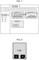
- a display form indicative of execution difficulty may be displayed as illustrated in a workflow C in Fig. 7 .
- the display form indicative of execution difficulty may be indicated by hatching.
- the display form indicative of execution difficulty may be indicated by a grayout area or by flashing.
- mouseover on a task for a predetermined time period may display an icon that is used to select whether to execute the task.
- Fig. 8 illustrates in a task icon an icon to execute the task (symbol " ⁇ " in Fig. 8 ) and an icon to cancel the task (symbol "x" in Fig. 8 ).
- mousing over the symbol O adds an action and mousing over the symbol x cancels the operation.
- a cancel region such as the x icon, is arranged such that the closest operation is cancelable.
- confirmation or cancellation may be instructed using a mouse action in order to confirm a nearby item or cancel the closest operation.
- the confirmation is instructed by drawing a trajectory of a circle near the task icon, and the closest operation may be canceled by drawing a zigzag line.
- a list of all tasks that are registerable as steps of a workflow may be displayed and a workflow obtained by freely combining tasks may be set on the spot.
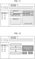
- a verification screen of the workflows selected heretofore may be displayed as illustrated in Fig. 12 . If only one workflow is used, that workflow is immediately performed without displaying the verification screen. If multiple workflows are used, the verification screen may be displayed. Alternatively, the verification screen may be displayed regardless of the number of workflows. Alternatively, a determination as to whether to display the verification screen may be switchable depending on user setting. Referring to Fig. 12 , the verification screen is displayed to display process contents of the selected workflow and to confirm whether to execute the workflow.
- a single workflow is executed starting with the middle thereof.
- the workflow includes the following steps:
- step 4 if a procedure of approval stamping has been executed offline, the workflow starts with step 4.
- workflows are consecutively performed.
- the workflows include the workflow A and the workflow B and each workflow may include the following steps.
- Step 1 A document is uploaded in a "contract” folder.
- Step 2 "An approval request is transmitted to a supervisor.”
- Step 1 A document is uploaded in a "contract” folder.
- Step 2 File is transferred to digital signature service.
- Step 3 Digitally signed file is transferred to client folder.
- the user may want to make the step of the approval request only or the step of digital signature only, or the steps of the approval request and digital signature.
- the steps may be freely combined in this way.
- Fig. 13 is a flowchart illustrating an example of a process flow that is executed by the information processing system 10 of the exemplary embodiment.
- the process illustrated in Fig. 13 is performed by a web application of the cloud server 16.
- the process illustrated in Fig. 13 starts when the information processing terminal 14 notifies the cloud server 16 that a file is dragged from a different window to the operation screen to mouse over a folder.
- step S100 the CPU 16A reads a workflow from a folder at a mouseover point, displays the workflow and then proceeds to step S102. Specifically, the CPU 16A acquires operation information on the information processing terminal 14, and determines whether the workflow set beforehand in the folder at the mouseover point is present on a database. If the workflow is present, the CPU 16A transmits the workflow to the information processing terminal 14. The CPU 16A thus displays the workflow on the display 14F of the information processing terminal 14. For example, the CPU 16A displays the name of the workflow set by the user on each workflow region. A button used to display all tasks specified in the workflow may be displayed. Each task set in the workflow may be displayed in the workflow region.
- step S102 the CPU 16A determines whether an operation to add a workflow or a task has been performed. The determination may be performed by acquiring the operation information on an operation unit 14E from the information processing terminal 14 and by determining that an mouseover operation has been performed with the file dragged to mouse over the region of the workflow or each task to be executed. If the yes path is followed in step S102, the CPU 16A proceeds to step S104; otherwise, the CPU 16A proceeds to step S108.
- step S104 the CPU 16A adds a target workflow or a target task to a queue and proceeds to step S106.
- the queue is a mechanism that is used to specify the execution or cancellation of the task.
- the addition or deletion of a workflow or a task to or from the queue and finally, the workflows or tasks remaining in the queue are executed in sequence from the beginning thereof.
- step S106 the CPU 16A updates file execution result prediction and proceeds to step S108. Specifically, the CPU 16A updates the thumbnail image 50 of the result prediction in response to the execution of the workflow or task added to the queue, transmits the updated thumbnail image 50 to the information processing terminal 14, and displays the updated thumbnail image 50 on the display 14F of the information processing terminal 14.
- step S108 the CPU 16A determines whether an operation to delete the closest workflow has been performed. For example, the determination may be performed by acquiring the operation information on the operation unit 14E from the information processing terminal 14 and determining whether a cancel operation has been performed using the cancel icon (the symbol x icon in Figs. 8 and 9 ) or in response to a mouse action. If the yes path is followed in step S108, the CPU 16A proceeds to step S110; otherwise, the CPU 16A proceeds to step S114.
- step S110 the CPU 16A deletes the closest workflow or task from the queue and proceeds to step S112. Specifically, the CPU 16A deletes the closest workflow or task as the target of the cancel operation from the queue.
- step S112 the CPU 16A updates the execution result prediction of the file and proceeds to step S114. Specifically, the CPU 16A generates the thumbnail image 50 of the execution result prediction in response to the deletion of the target workflow or task from the queue, transmits the generated thumbnail image 50 to the information processing terminal 14, and displays the generated thumbnail image 50 on the display 14F of the information processing terminal 14.
- step S114 the CPU 16A determines whether an operation to cancel the execution specified task has been performed. Like the determination operation in step S108, the determination may be performed by determining whether the cancel operation has been performed using the cancel icon (the symbol x icon in Figs. 8 and 9 ) or in response to a mouse action. If the yes path is followed in step S114, the CPU 16A proceeds to step S116; otherwise, the CPU 16A proceeds to step S120.
- step S116 the CPU 16A deletes the specified workflow or task and proceeds to step S118. Specifically, the CPU 16A deletes from the queue the specified workflow or task responsive to the cancel operation.
- step S118 the CPU 16A updates the execution result prediction of the file and proceeds to step S120.
- the CPU 16A generates the thumbnail image 50 of the execution result prediction responsive to the deletion of the target workload and task from the queue, transmits the generated thumbnail image 50 to the information processing terminal 14, and displays the generated thumbnail image 50 on the display 14F of the information processing terminal 14.
- step S120 the CPU 16A determines whether the file has been dropped. The determination may be performed by acquiring the operation information from the information processing terminal 14 and then determines whether the file has been dropped. If the no path is followed in step S120, the CPU 16A returns to step S100 to repeat step S100 and subsequent steps; otherwise, the CPU 16A proceeds to step S122.
- step S122 the CPU 16A executes the workflow added to the queue and ends the process.
- the cloud server 16 performs the process in Fig. 13 .
- an application that uses the file upload and sharing service may be installed on the information processing terminal 14 including a terminal apparatus and the information processing terminal 14 may perform the process in Fig. 13 .
- the process in Fig. 13 performed by the information processing terminal 14 is described herein.
- the information processing terminal 14 functions as an information processing apparatus.
- step S100 a CPU 14A in the information processing terminal 14 acquires a workflow from the cloud server 16 by requesting the cloud server 16 to read the workflow set in a folder at a mouseover point, and displays the workflow on the display 14F.
- step S102 the CPU 14A determines whether an operation to add a workflow or task has been performed. For example, the determination may be performed by determining whether the operation of the operation unit 14E has dragged the file to mouse over the region of the workflow or task to be executed. If the yes path is followed in step S102, the CPU 14A proceeds to step S104; otherwise, the CPU 14A proceeds to step S108.
- step S104 the CPU 14A requests the cloud server 16 to add a target workflow or task to a queue and then proceeds to step S106. In this way, the cloud server 16 adds the target workflow or task to the queue.
- step S106 the CPU 14A acquires from the cloud server 16 the thumbnail image 50 with the file execution result prediction updated, displays the updated thumbnail image 50 on the display 14F, and proceeds to step S108.
- the cloud server 16 generates the thumbnail image 50 having the file execution result prediction updated in response to the execution of the workflow or task in the queue.
- the cloud server 16 then transmits the generated thumbnail image 50 to the information processing terminal 14.
- step S108 the CPU 14A determines whether the operation to delete the closest workflow has been performed. For example, the determination may be performed by determining whether the operation unit 14E has performed the cancel operation using the cancel icon (the symbol x icon in Figs. 8 and 9 ) or in response to a mouse action. If the yes path is followed in step S108, the CPU 14A proceeds to step S110; otherwise, the CPU 14A proceeds to step S114.
- step S110 the CPU 14A requests the cloud server 16 to delete the closest workflow or task from the queue and then proceeds to step S112.
- the cloud server 16 deletes the closest workflow or task from the queue in response to the cancel operation.
- step S112 the CPU 14A acquires from the cloud server 16 the thumbnail image 50 with the file execution result prediction updated, displays the updated thumbnail image 50 on the display 14F, and proceeds to step S114.
- the cloud server 16 generates the thumbnail image 50 with the file execution result prediction updated in response to the execution of the workflow or task in the queue.
- the cloud server 16 then transmits the generated thumbnail image 50 to the information processing terminal 14.
- step S114 the CPU 14A determines whether an operation to cancel the execution specified task has been performed. Like the determination operation in step S108, the determination may be performed by determining whether the cancel operation has been performed using the cancel icon (the symbol x icon in Figs. 8 and 9 ) or in response to a mouse action. If the yes path is followed in step S114, the CPU 14A proceeds to step S116; otherwise, the CPU 14A proceeds to step S120.
- step S116 the CPU 14A requests the cloud server 16 to delete the specified workflow or task and proceeds to step S118. Specifically, the cloud server 16 deletes from the queue the specified workflow or task in response to the cancel operation.
- step S118 the CPU 14A acquires from the cloud server 16 the thumbnail image 50 with the file execution result prediction updated, displays the updated thumbnail image 50 on the display 14F, and proceeds to step S120.
- the cloud server 16 generates the thumbnail image 50 with the file execution result prediction updated in response to the execution of the workflow or task in the queue.
- the cloud server 16 then transmits the generated thumbnail image 50 to the information processing terminal 14.
- step S120 the CPU 14A determines whether the file has been dropped. For example, the determination may be performed by determining whether the operation unit 14E has dropped the file. If the no path is followed in step S120, the CPU 14A returns to step S100 to repeat step S100 and subsequent steps; otherwise, the CPU 14A proceeds to step S122.
- step S122 the CPU 14A executes the workflow by requesting the cloud server 16 to execute the workflow added to the queue and thus ends the process.
- the cloud server 16 or the information processing terminal 14 is an information processing apparatus.
- the whole information processing system 10 may be an information processing apparatus.
- processor refers to hardware in a broad sense.
- Examples of the processor include general processors (e.g., CPU: Central Processing Unit) and dedicated processors (e.g., GPU: Graphics Processing Unit, ASIC: Application Specific Integrated Circuit, FPGA: Field Programmable Gate Array, and programmable logic device).
- processor is broad enough to encompass one processor or plural processors in collaboration which are located physically apart from each other but may work cooperatively.
- the order of operations of the processor is not limited to one described in the embodiments above, and may be changed.
- the process performed by the information processing system 10 of the exemplary embodiment may be executed using software, hardware, or a combination thereof.
- the process performed by the information processing system 10 may be implemented by a computer program that is distributed in a recorded form on a recording medium.
Landscapes
- Engineering & Computer Science (AREA)
- Theoretical Computer Science (AREA)
- General Engineering & Computer Science (AREA)
- Physics & Mathematics (AREA)
- General Physics & Mathematics (AREA)
- Business, Economics & Management (AREA)
- Human Computer Interaction (AREA)
- Strategic Management (AREA)
- Human Resources & Organizations (AREA)
- Data Mining & Analysis (AREA)
- Entrepreneurship & Innovation (AREA)
- Databases & Information Systems (AREA)
- Operations Research (AREA)
- Marketing (AREA)
- Economics (AREA)
- Quality & Reliability (AREA)
- Tourism & Hospitality (AREA)
- General Business, Economics & Management (AREA)
- User Interface Of Digital Computer (AREA)
- Management, Administration, Business Operations System, And Electronic Commerce (AREA)
- Facsimiles In General (AREA)
Abstract
Description
- The present disclosure relates to an information processing apparatus, an information processing program, and an information processing method
-
Japanese Unexamined Patent Application Publication No. 2012-185838 -
Japanese Unexamined Patent Application Publication No. 2021-027539 -
Japanese Unexamined Patent Application Publication No. 2012-088912 - According to a disclosed technique, a workflow is set beforehand in a folder and is executed when a file is dragged and dropped onto the folder. However, if the workflow set in the folder has multiple steps, execution of part of the workflow is not so easy. For example, the execution of the workflow starting with an intermediate step or the execution of the workflow after editing the workflow is not so easy. A new workflow is to be produced in order to execute the workflow starting with the intermediate step or execute the workflow after editing.
- Accordingly, it is an object of the present disclosure to provide an information processing apparatus, an information processing program, and an information processing method enabled to execute a partial workflow in response to a simple operation in an easier way than when a workflow is newly produced.
- According to a first aspect of the present disclosure, there is provided an information processing apparatus including a processor configured to: if a file serving as a process target is dragged to a folder where a workflow including multiple steps is set beforehand, display the steps included in the workflow set in the folder; and if the file is dropped onto a step of interest out of the displayed steps, perform a process of executing the workflow, starting with the step of interest.
- According to a second aspect of the disclosure, there is provided an information processing apparatus comprising a processor configured to: display both a folder where a workflow including a plurality of steps is set beforehand and the steps of the workflow set in the folder; edit the displayed workflow using a trajectory along which a file serving as a process target has been dragged; and if the file is dropped, perform a process that executes the edited workflow.
- According to a third aspect of the disclosure in view of the first aspect, the processor in the information processing apparatus is configured to, if the file is dragged to the step of interest, further display process contents of each of the steps of the workflow, starting with the step of interest.
- According to a fourth aspect of the disclosure in view of one of the first and third aspects, the processor in the information processing apparatus is configured to, if the file is dragged to the step of interest, further display execution result prediction of execution of the workflow starting with the step of interest.
- According to a fifth aspect of the disclosure in view of the fourth aspect, the processor in the information processing apparatus is configured to, if the file is dragged over the displayed execution result prediction and dropped onto a second workflow, execute the second workflow in succession to the workflow of the execution result prediction.
- According to a sixth aspect of the disclosure in view of one of the first and third aspects, the processor in the information processing apparatus is configured to, if an infeasible step is present, display the infeasible step in a display form indicative of infeasibility.
- According to a seventh aspect of the disclosure in view of the first and second aspects, the processor in the information processing apparatus is configured to select, out of the displayed steps, a step to be executed, by using a trajectory along which the file has been dragged.
- According to an eighth aspect of the disclosure in view of the seventh aspect, the processor in the information processing apparatus is configured to select, as an execution target out of the displayed steps, a step that has undergone a predetermined operation.
- According to a ninth aspect of the disclosure in view of the eighth aspect, in the information processing apparatus, the predetermined operation is to position the file on the step of interest until a predetermined time duration elapses with the file in a dragged state.
- According to a tenth aspect of the disclosure in view of the second aspect, the processor in the information processing apparatus is configured to further display a step that is enabled to be registered as a step of the workflow.
- According to an eleventh aspect of the disclosure, there is provide an information processing program causing a computer to execute a process, the process including: if a file serving as a process target is dragged to a folder where a workflow including a plurality of steps is set beforehand, displaying the steps included in the workflow set in the folder; and if the file is dropped onto a step of interest out of the displayed steps, performing a process of executing the workflow, starting with the step of interest.
- According to a twelfth aspect of the disclosure, there is provided an information processing method including: if a file serving as a process target is dragged to a folder where a workflow including a plurality of steps is set beforehand, displaying the steps included in the workflow set in the folder; and if the file is dropped onto a step of interest out of the displayed steps, performing a process of executing the workflow, starting with the step of interest.
- The information processing apparatus provided according to the first aspect may execute part of the workflow in response to a simpler operation than when a new workflow is produced.
- The information processing apparatus provided according to the second aspect may execute part of the workflow in response to a simpler operation when a new workflow is produced.
- According to the third aspect, process contents may be verified when the workflow is executed starting with an intermediate step.
- According to the fourth aspect, execution result prediction may be verified when the workflow is executed starting with the intermediate step.
- According to the fifth aspect, multiple workflows may be consecutively executed.
- According to the sixth aspect, an executable step may be recognized.
- According to the seventh aspect, a step that is to be performed in a more intuitive manner may be determined than when a keyboard or the like is operated.
- According to the eighth aspect, a step to be executed may be selected from a trajectory along which a file is dragged.
- According to the ninth aspect, a step to be executed may be selected without operating the keyboard or the like from the trajectory along which the file is dragged.
- According to the tenth aspect, a step to be executed in the workflow may be added.
- The information processing program provided according to the eleventh aspect may execute part of the workflow in a simpler operation than when a new workflow is produced.
- The information processing method provided according to the twelfth aspect may execute part of the workflow in a simpler operation than when a new workflow is produced.
- Exemplary embodiment of the present disclosure will be described in detail based on the following figures, wherein:
-
Fig. 1 illustrates a configuration of an information processing system of an exemplary embodiment; -
Fig. 2 is a block diagram illustrating an electrical configuration of a major portion of an image forming apparatus of the exemplary embodiment; -
Fig. 3 is a block diagram illustrating an electrical configuration of a major portion of an information processing terminal and cloud server of the exemplary embodiment; -
Fig. 4 illustrates an example of displayed workflows that are set beforehand in a currently displayed folder; -
Fig. 5 illustrates an example of displayed workflows that are set beforehand in a folder at a mouseover point; -
Fig. 6 illustrates an example of each displayed task set in each workflow; -
Fig. 7 illustrates workflows that are consecutively executed; -
Fig. 8 illustrates an example of a displayed icon providing an instruction in a task icon; -
Fig. 9 illustrates a cancel region that is placed on a screen; -
Fig. 10 illustrates an example where conformation and canceling are performed in response to a mouse action; -
Fig. 11 illustrates an example of a workflow that is set by displaying a list of all tasks; -
Fig. 12 illustrates an example of a displayed verification screen of the workflow; and -
Fig. 13 is a flowchart illustrating an example of a process flow that is executed by the information processing system of the exemplary embodiment. - Exemplary embodiment of the disclosure is described in detail below with reference to the drawings. For example, the exemplary embodiment is related to an
information processing system 10 that includes multiple image forming apparatuses, multiple information processing terminals, and an information processing apparatus serving as a cloud server, interconnected to each other via a communication network.Fig. 1 illustrates the configuration of theinformation processing system 10 of the exemplary embodiment. - Referring to
Fig. 1 , theinformation processing system 10 of the exemplary embodiment includes image forming apparatuses 12a, 12b, ..., information processing terminals 14a, 14b, ..., andcloud server 16. If the image forming apparatuses 12a, 12b, ... are not differentiated from each other, each image forming apparatus is collectively referred to as animage forming apparatus 12. If the information processing terminals 14a, 14b, ... are not differentiated from each other, each information processing terminal is collectively referred to as an information processing terminal 14. In the discussion of the exemplary embodiment, the image forming apparatuses 12a, 12b, ..., and the information processing terminals 14a, 14b, ... are employed. The number ofimage forming apparatuses 12 may be one or more, and the number of information processing terminals 14 may be one or more. - The
image forming apparatus 12, information processing terminal 14, andcloud server 16 are interconnected to each other via thecommunication network 18 including a local-area network (LAN), wide-area network (WAN), Internet, and/or intranet. Theimage forming apparatus 12, information processing terminal 14, andcloud server 16 may exchange a variety of data with each other via thecommunication network 18. -
Fig. 2 is a block diagram illustrating an electrical configuration of a major portion of theimage forming apparatus 12 of the exemplary embodiment. - The
image forming apparatus 12 of the exemplary embodiment includes acontrol unit 20 including a central processing unit (CPU) 20A, read-only memory (ROM) 20B, random-access memory (RAM) 20C as illustrated inFig. 3 . TheCPU 20A controls the entire operation of theimage forming apparatus 12. TheRAM 20C is used as a work area when theCPU 20A executes a variety of programs. TheROM 20B stores beforehand a variety of control programs and a variety of parameters. Each section of thecontrol unit 20 is electrically connected to elements of theimage forming apparatus 12 via asystem bus 42. - The
image forming apparatus 12 of the exemplary embodiment includes a hard disk drive (HDD) 26 that stores a variety of data and a variety of application programs. Theimage forming apparatus 12 further includes adisplay controller 28 that is connected to auser interface 22 and controls displaying of a variety of operation screens onto theuser interface 22. Theimage forming apparatus 12 further includes anoperation input detector 30 that is connected to theuser interface 22 and detects an operation instruction that is received via theuser interface 22. In theimage forming apparatus 12, theHDD 26,display controller 28, andoperation input detector 30 are electrically connected to thesystem bus 42. Theimage forming apparatus 12 of the exemplary embodiment includes theHDD 26 as a memory. Alternatively, theimage forming apparatus 12 may include a non-volatile memory, such as a flash memory. - The
image forming apparatus 12 includes a readingcontroller 32 andimage formation controller 34. The readingcontroller 32 controls a reading operation that adocument reader 44 performs to optically read an image and also controls a document transport operation that a document transporter performs. Theimage formation controller 34 controls an image forming operation performed by an image former 24 and paper transportation that thetransporter 25 performs to transport paper sheet to the image former 24. Theimage forming apparatus 12 further includes a communication network interface (I/F) 36 that is connected to thecommunication network 18 and transmits or receives communication data to or from an external apparatus, such as thecloud server 16 connected to thecommunication network 18. Theimage forming apparatus 12 further includes a facsimile I/F 38 that is connected to a telephone network (not illustrated) and transmits or receives facsimile data to or from a facsimile machine via the telephone network. Theimage forming apparatus 12 further includes a transmit-receivecontroller 40 that transmits or receives facsimile data via the facsimile I/F 38. In theimage forming apparatus 12, the transmit-receivecontroller 40, readingcontroller 32,image formation controller 34, communication network I/F 36, facsimile I/F 38, and log collector 46 are electrically connected to thesystem bus 42. - In the configuration described above, the
CPU 20A in theimage forming apparatus 12 of the exemplary embodiment accesses each of theRAM 20C,ROM 20B, andHDD 26. Using thedisplay controller 28, theCPU 20A in theimage forming apparatus 12 controls displaying of an operation screen and information including a variety of messages on a display 22A of theuser interface 22. Using the readingcontroller 32, theCPU 20A in theimage forming apparatus 12 controls the operation of thedocument reader 44 and document transporter. Using theimage formation controller 34, theCPU 20A in theimage forming apparatus 12 controls the operation of the image former 24 andtransporter 25 and transmission and reception of communication data via the communication network I/F 36. Using the transmit-receivecontroller 40, theCPU 20A in theimage forming apparatus 12 controls the transmission and reception of facsimile data via the facsimile I/F 38. TheCPU 20A in theimage forming apparatus 12 recognizes contents of operation of theuser interface 22 in accordance with operation information detected by theoperation input detector 30 and performs various control operations responsive to the contents of operation. - The electrical configuration of a major portion of the information processing terminal 14 and
cloud server 16 of the exemplary embodiment is described below.Fig. 3 is a block diagram illustrating the electrical configuration of the major portion of the information processing terminal 14 andcloud server 16. Each of the information processing terminal 14 andcloud server 16 has a typical computer configuration. Only thecloud server 16 is representatively described herein. - As illustrated in
Fig. 3 , thecloud server 16 of the exemplary embodiment includes aCPU 16A,ROM 16B,RAM 16C,HDD 16D,operation unit 16E,display 16F, and communication network interface (I/F) 16G. TheCPU 16A controls the whole operation of thecloud server 16. TheROM 16B pre-stores a variety of control programs and a variety of parameters. TheRAM 16C is used as a work area when theCPU 16A performs the variety of programs. TheHDD 16D stores a variety of data and a variety of application programs. Theoperation unit 16E includes a keyboard and/or mouse and is used to enter a variety of information. Thedisplay 16F displays a variety of information. The communication network I/F 16G is connected to thecommunication network 18 and transmits and receivers a variety of data to and from another apparatus connected to thecommunication network 18. The elements of thecloud server 16 are electrically connected to asystem bus 16H. Thecloud server 16 of the exemplary embodiment includes theHDD 16D as the memory thereof. Alternatively, thecloud server 16 may include a non-volatile memory, such as a flash memory. - In the configuration described above, the
CPU 16A in thecloud server 16 of the exemplary embodiment accesses each of theROM 16B,RAM 16C, andHDD 16D, acquires a variety of data via theoperation unit 16E, and displays a variety of information on thedisplay 16F. TheCPU 16A in thecloud server 16 controls the transmission and reception of the communication data via the communication network I/F 16G. - According to the exemplary embodiment, in the
information processing system 10 thus configured, cloud service provided by thecloud server 16 may be used via the information processing terminal 14. According to the exemplary embodiment, thecloud server 16 provides, as a cloud service, a file upload and sharing service that is used to upload and share a file. - The file upload and sharing service to share a file with another apparatus is enjoyed by uploading the file onto the
cloud server 16. The file upload and sharing service has a function that allows a workflow including multiple steps to be registered and executes the registered workflow. The workflow includes steps, such as application and approval, and is used to perform, for example, an operation to transmit information, such as a form, to the information processing terminal 14 of a person in charge of each step. In the discussion that follows, each step of the workflow is referred to as a task. - The execution method of a registered workflow in the file upload and sharing service is described below. In the following discussion, an operation of overlapping a mouse pointer onto a target is referred to a mouseover.
- Accessing the
cloud server 16 using the information processing terminal 14 allows a predetermined operation screen in the file upload and sharing service to be received from thecloud server 16 and the operation screen to be displayed on adisplay 14F of the information processing terminal 14. - When a user drags a file from another window to the operation screen, the workflow predetermined in a currently displayed folder is displayed as illustrated in
Fig. 4 . Alternatively, the workflow preset in a moused over folder is displayed as illustrated inFig. 5 . A blank point on the screen, if moused over, is regarded as uploading to the currently displayed folder and a workflow set in the currently displayed folder is displayed on the entire screen. Alternatively, if a specific folder is moused over as illustrated inFig. 5 , a workflow set in the specific folder may be popped up or may be displayed on the entire screen. - When workflows are displayed as illustrated in
Fig. 6 , tasks set in each workflow may be displayed. Referring toFig. 6 , three tasks are set in each of the three workflows A through C. - By dropping the file in a region excluding the tasks of the workflow, or in any of the tasks, the user executes the workflow. When the file is dropped in a task-free region as illustrated in the workflow A in
Fig. 6 , the workflow is executed starting with the first task thereof in accordance with the exemplary embodiment. When the file is dropped in a task in the workflow as illustrated in the workflow B inFig. 6 , the workflow is executed starting with the task where the file is dropped in the middle of the workflow. In this way, a partial workflow is executed in response to a simple operation in a manner free from returning to the setting screen of the workflow and starting over after interrupting the uploading and movement of the file. - During the mouseover, a
thumbnail image 50 of result prediction after the execution of the task is displayed as illustrated inFig. 6 . The resultprediction thumbnail image 50 may be displayed behind the tasks or in a dedicated region. A list ofworkflows 52 indicating contents of a process to be executed may be separately displayed. - According to the exemplary embodiment, operations of editing and executing the workflow may be performed using a trajectory along which the file is dragged.
- If workflows are consecutively executable, for example, if two document editing workflows are present, the file is dragged and pulled by way of the
thumbnail image 50 displayed in the result prediction and dropped onto a next workflow. In this way, multiple workflows are specified for execution at any sequence. For example, as illustrated inFig. 7 , the file is dragged to mouse over the region of the workflow A such that thethumbnail image 50 of the result prediction responsive to the execution of the workflow A is displayed. Thethumbnail image 50 may be pulled by performing a predetermined operation, such as by dragging the file over thethumbnail image 50, by placing the mouse over thethumbnail image 50 for the elapse of a predetermined time period, or operating a control key or the like on thethumbnail image 50. By placing the mouse over the workflow B with thethumbnail image 50 pulled, thethumbnail image 50 of the result prediction responsive to the execution of the workflow B is displayed after performing the workflow A, and then, by dropping the file, two workflows are consecutively performed. - In order to execute a task in the middle of the workflow A, the user drags the file to the target task and displays the
thumbnail image 50 responsive to the execution of the task in the middle of the workflow A. Also, in order to execute a task in the middle of the workflow B the user wants to execute in succession, the user may simply drag the file to mouse over the task in the middle and then drop the file. - Consecutive execution may be difficult, or execution of one file may be difficult if the number of files to be dropped is plural. In such a case, drop destinations may be consecutively invalidated, an error indicator may be displayed, or specifying a file may be followed by editing. For example, if there is a step that is difficult to execute, a display form indicative of execution difficulty may be displayed as illustrated in a workflow C in
Fig. 7 . Referring to the workflow C inFig. 7 , the display form indicative of execution difficulty may be indicated by hatching. The display form indicative of execution difficulty may be indicated by a grayout area or by flashing. - When workflows or tasks are consecutively executed, mouseover on a task for a predetermined time period may display an icon that is used to select whether to execute the task. For example,
Fig. 8 illustrates in a task icon an icon to execute the task (symbol "○" inFig. 8 ) and an icon to cancel the task (symbol "x" inFig. 8 ). Referring toFig. 8 , mousing over the symbol O adds an action and mousing over the symbol x cancels the operation. - Referring to
Fig. 9 , a cancel region, such as the x icon, is arranged such that the closest operation is cancelable. Alternatively, referring toFig. 10 , confirmation or cancellation may be instructed using a mouse action in order to confirm a nearby item or cancel the closest operation. Referring toFig. 10 , the confirmation is instructed by drawing a trajectory of a circle near the task icon, and the closest operation may be canceled by drawing a zigzag line. - Referring to
Fig. 11 , a list of all tasks that are registerable as steps of a workflow may be displayed and a workflow obtained by freely combining tasks may be set on the spot. - When the file is dropped, a verification screen of the workflows selected heretofore may be displayed as illustrated in
Fig. 12 . If only one workflow is used, that workflow is immediately performed without displaying the verification screen. If multiple workflows are used, the verification screen may be displayed. Alternatively, the verification screen may be displayed regardless of the number of workflows. Alternatively, a determination as to whether to display the verification screen may be switchable depending on user setting. Referring toFig. 12 , the verification screen is displayed to display process contents of the selected workflow and to confirm whether to execute the workflow. - In the following specific example, a single workflow is executed starting with the middle thereof. The workflow includes the following steps:
- Step 1 A document is uploaded in a "contract" folder.
- Step 2 "An approval request is transmitted to a supervisor."
- Step 3 "If the supervisor has approved, a file is transferred to digital signature service."
- Step 4 "Digitally signed file is transferred to a client folder."
- According to the exemplary embodiment, if a procedure of approval stamping has been executed offline, the workflow starts with step 4.
- In the following discussion, different workflows are consecutively performed. In the same procedure described above, the workflows include the workflow A and the workflow B and each workflow may include the following steps.
- Step 1 A document is uploaded in a "contract" folder.
- Step 2 "An approval request is transmitted to a supervisor."
- Step 1 A document is uploaded in a "contract" folder.
- Step 2 "File is transferred to digital signature service."
- Step 3 "Digitally signed file is transferred to client folder."
- According to the exemplary embodiment, the user may want to make the step of the approval request only or the step of digital signature only, or the steps of the approval request and digital signature. The steps may be freely combined in this way.
- A specific process of the
information processing system 10 of the exemplary embodiment is described below.Fig. 13 is a flowchart illustrating an example of a process flow that is executed by theinformation processing system 10 of the exemplary embodiment. The process illustrated inFig. 13 is performed by a web application of thecloud server 16. For example, the process illustrated inFig. 13 starts when the information processing terminal 14 notifies thecloud server 16 that a file is dragged from a different window to the operation screen to mouse over a folder. - In step S100, the
CPU 16A reads a workflow from a folder at a mouseover point, displays the workflow and then proceeds to step S102. Specifically, theCPU 16A acquires operation information on the information processing terminal 14, and determines whether the workflow set beforehand in the folder at the mouseover point is present on a database. If the workflow is present, theCPU 16A transmits the workflow to the information processing terminal 14. TheCPU 16A thus displays the workflow on thedisplay 14F of the information processing terminal 14. For example, theCPU 16A displays the name of the workflow set by the user on each workflow region. A button used to display all tasks specified in the workflow may be displayed. Each task set in the workflow may be displayed in the workflow region. - In step S102, the
CPU 16A determines whether an operation to add a workflow or a task has been performed. The determination may be performed by acquiring the operation information on anoperation unit 14E from the information processing terminal 14 and by determining that an mouseover operation has been performed with the file dragged to mouse over the region of the workflow or each task to be executed. If the yes path is followed in step S102, theCPU 16A proceeds to step S104; otherwise, theCPU 16A proceeds to step S108. - In step S104, the
CPU 16A adds a target workflow or a target task to a queue and proceeds to step S106. The queue is a mechanism that is used to specify the execution or cancellation of the task. The addition or deletion of a workflow or a task to or from the queue and finally, the workflows or tasks remaining in the queue are executed in sequence from the beginning thereof. - In step S106, the
CPU 16A updates file execution result prediction and proceeds to step S108. Specifically, theCPU 16A updates thethumbnail image 50 of the result prediction in response to the execution of the workflow or task added to the queue, transmits the updatedthumbnail image 50 to the information processing terminal 14, and displays the updatedthumbnail image 50 on thedisplay 14F of the information processing terminal 14. - In step S108, the
CPU 16A determines whether an operation to delete the closest workflow has been performed. For example, the determination may be performed by acquiring the operation information on theoperation unit 14E from the information processing terminal 14 and determining whether a cancel operation has been performed using the cancel icon (the symbol x icon inFigs. 8 and9 ) or in response to a mouse action. If the yes path is followed in step S108, theCPU 16A proceeds to step S110; otherwise, theCPU 16A proceeds to step S114. - In step S110, the
CPU 16A deletes the closest workflow or task from the queue and proceeds to step S112. Specifically, theCPU 16A deletes the closest workflow or task as the target of the cancel operation from the queue. - In step S112, the
CPU 16A updates the execution result prediction of the file and proceeds to step S114. Specifically, theCPU 16A generates thethumbnail image 50 of the execution result prediction in response to the deletion of the target workflow or task from the queue, transmits the generatedthumbnail image 50 to the information processing terminal 14, and displays the generatedthumbnail image 50 on thedisplay 14F of the information processing terminal 14. - In step S114, the
CPU 16A determines whether an operation to cancel the execution specified task has been performed. Like the determination operation in step S108, the determination may be performed by determining whether the cancel operation has been performed using the cancel icon (the symbol x icon inFigs. 8 and9 ) or in response to a mouse action. If the yes path is followed in step S114, theCPU 16A proceeds to step S116; otherwise, theCPU 16A proceeds to step S120. - In step S116, the
CPU 16A deletes the specified workflow or task and proceeds to step S118. Specifically, theCPU 16A deletes from the queue the specified workflow or task responsive to the cancel operation. - In step S118, the
CPU 16A updates the execution result prediction of the file and proceeds to step S120. TheCPU 16A generates thethumbnail image 50 of the execution result prediction responsive to the deletion of the target workload and task from the queue, transmits the generatedthumbnail image 50 to the information processing terminal 14, and displays the generatedthumbnail image 50 on thedisplay 14F of the information processing terminal 14. - In step S120, the
CPU 16A determines whether the file has been dropped. The determination may be performed by acquiring the operation information from the information processing terminal 14 and then determines whether the file has been dropped. If the no path is followed in step S120, theCPU 16A returns to step S100 to repeat step S100 and subsequent steps; otherwise, theCPU 16A proceeds to step S122. - In step S122, the
CPU 16A executes the workflow added to the queue and ends the process. - In the exemplary embodiment, the
cloud server 16 performs the process inFig. 13 . Alternatively, an application that uses the file upload and sharing service may be installed on the information processing terminal 14 including a terminal apparatus and the information processing terminal 14 may perform the process inFig. 13 . The process inFig. 13 performed by the information processing terminal 14 is described herein. In this case, the information processing terminal 14 functions as an information processing apparatus. - In step S100, a
CPU 14A in the information processing terminal 14 acquires a workflow from thecloud server 16 by requesting thecloud server 16 to read the workflow set in a folder at a mouseover point, and displays the workflow on thedisplay 14F. - In step S102, the
CPU 14A determines whether an operation to add a workflow or task has been performed. For example, the determination may be performed by determining whether the operation of theoperation unit 14E has dragged the file to mouse over the region of the workflow or task to be executed. If the yes path is followed in step S102, theCPU 14A proceeds to step S104; otherwise, theCPU 14A proceeds to step S108. - In step S104, the
CPU 14A requests thecloud server 16 to add a target workflow or task to a queue and then proceeds to step S106. In this way, thecloud server 16 adds the target workflow or task to the queue. - In step S106, the
CPU 14A acquires from thecloud server 16 thethumbnail image 50 with the file execution result prediction updated, displays the updatedthumbnail image 50 on thedisplay 14F, and proceeds to step S108. Thecloud server 16 generates thethumbnail image 50 having the file execution result prediction updated in response to the execution of the workflow or task in the queue. Thecloud server 16 then transmits the generatedthumbnail image 50 to the information processing terminal 14. - In step S108, the
CPU 14A determines whether the operation to delete the closest workflow has been performed. For example, the determination may be performed by determining whether theoperation unit 14E has performed the cancel operation using the cancel icon (the symbol x icon inFigs. 8 and9 ) or in response to a mouse action. If the yes path is followed in step S108, theCPU 14A proceeds to step S110; otherwise, theCPU 14A proceeds to step S114. - In step S110, the
CPU 14A requests thecloud server 16 to delete the closest workflow or task from the queue and then proceeds to step S112. Thecloud server 16 deletes the closest workflow or task from the queue in response to the cancel operation. - In step S112, the
CPU 14A acquires from thecloud server 16 thethumbnail image 50 with the file execution result prediction updated, displays the updatedthumbnail image 50 on thedisplay 14F, and proceeds to step S114. Thecloud server 16 generates thethumbnail image 50 with the file execution result prediction updated in response to the execution of the workflow or task in the queue. Thecloud server 16 then transmits the generatedthumbnail image 50 to the information processing terminal 14. - In step S114, the
CPU 14A determines whether an operation to cancel the execution specified task has been performed. Like the determination operation in step S108, the determination may be performed by determining whether the cancel operation has been performed using the cancel icon (the symbol x icon inFigs. 8 and9 ) or in response to a mouse action. If the yes path is followed in step S114, theCPU 14A proceeds to step S116; otherwise, theCPU 14A proceeds to step S120. - In step S116, the
CPU 14A requests thecloud server 16 to delete the specified workflow or task and proceeds to step S118. Specifically, thecloud server 16 deletes from the queue the specified workflow or task in response to the cancel operation. - In step S118, the
CPU 14A acquires from thecloud server 16 thethumbnail image 50 with the file execution result prediction updated, displays the updatedthumbnail image 50 on thedisplay 14F, and proceeds to step S120. Thecloud server 16 generates thethumbnail image 50 with the file execution result prediction updated in response to the execution of the workflow or task in the queue. Thecloud server 16 then transmits the generatedthumbnail image 50 to the information processing terminal 14. - In step S120, the
CPU 14A determines whether the file has been dropped. For example, the determination may be performed by determining whether theoperation unit 14E has dropped the file. If the no path is followed in step S120, theCPU 14A returns to step S100 to repeat step S100 and subsequent steps; otherwise, theCPU 14A proceeds to step S122. - In step S122, the
CPU 14A executes the workflow by requesting thecloud server 16 to execute the workflow added to the queue and thus ends the process. - As described above, the
cloud server 16 or the information processing terminal 14 is an information processing apparatus. Alternatively, the wholeinformation processing system 10 may be an information processing apparatus. - In the embodiments above, the term "processor" refers to hardware in a broad sense. Examples of the processor include general processors (e.g., CPU: Central Processing Unit) and dedicated processors (e.g., GPU: Graphics Processing Unit, ASIC: Application Specific Integrated Circuit, FPGA: Field Programmable Gate Array, and programmable logic device).
- In the embodiments above, the term "processor" is broad enough to encompass one processor or plural processors in collaboration which are located physically apart from each other but may work cooperatively. The order of operations of the processor is not limited to one described in the embodiments above, and may be changed.
- The process performed by the
information processing system 10 of the exemplary embodiment may be executed using software, hardware, or a combination thereof. The process performed by theinformation processing system 10 may be implemented by a computer program that is distributed in a recorded form on a recording medium. - The disclosure is not limited to the exemplary embodiment described above. A variety of changes may be implemented in the exemplary embodiment without departing from the spirit of the disclosure.
- The foregoing description of the exemplary embodiments of the present disclosure has been provided for the purposes of illustration and description. It is not intended to be exhaustive or to limit the disclosure to the precise forms disclosed. Obviously, many modifications and variations will be apparent to practitioners skilled in the art. The embodiments were chosen and described in order to best explain the principles of the disclosure and its practical applications, thereby enabling others skilled in the art to understand the disclosure for various embodiments and with the various modifications as are suited to the particular use contemplated. It is intended that the scope of the disclosure be defined by the following claims and their equivalents.
Claims (12)
- An information processing apparatus comprising:
a processor configured to:if a file serving as a process target is dragged to a folder where a workflow including a plurality of steps is set beforehand, display the steps included in the workflow set in the folder; andif the file is dropped onto a step of interest out of the steps displayed, perform a process of executing the workflow, starting with the step of interest. - An information processing apparatus comprising:
a processor configured to:display both a folder where a workflow including a plurality of steps is set beforehand and the steps of the workflow set in the folder;edit the displayed workflow using a trajectory along which a file serving as a process target has been dragged; andif the file is dropped, perform a process that executes the edited workflow. - The information processing apparatus according to Claim 1, wherein the processor is configured to, if the file is dragged to the step of interest, further display process contents of each of the steps of the workflow, starting with the step of interest.
- The information processing apparatus according to one of Claims 1 and 3, wherein the processor is configured to, if the file is dragged to the step of interest, further display execution result prediction of execution of the workflow starting with the step of interest.
- The information processing apparatus according to Claim 4, wherein the processor is configured to, if the file is dragged over the displayed execution result prediction and dropped onto a second workflow, execute the second workflow in succession to the workflow of the execution result prediction.
- The information processing apparatus according to one of Claims 1 and 2, wherein the processor is configured to, if an infeasible step is present, display the infeasible step in a display form indicative of infeasibility.
- The information processing apparatus according to one of Claims 1 and 2, wherein the processor is configured to select, out of the displayed steps, a step to be executed, by using a trajectory along which the file has been dragged.
- The information processing apparatus according to Claim 7, wherein the processor is configured to select, as an execution target out of the displayed steps, a step that has undergone a predetermined operation.
- The information processing apparatus according to Claim 8, wherein the predetermined operation is to position the file on the step of interest until a predetermined time duration elapses with the file in a dragged state.
- The information processing apparatus according to Claim 2, wherein the processor is configured to further display a step that is enabled to be registered as a step of the workflow.
- An information processing program causing a computer to execute a process, the process comprising:if a file serving as a process target is dragged to a folder where a workflow including a plurality of steps is set beforehand, displaying the steps included in the workflow set in the folder; andif the file is dropped onto a step of interest out of the displayed steps, performing a process of executing the workflow, starting with the step of interest.
- An information processing method comprising:if a file serving as a process target is dragged to a folder where a workflow including a plurality of steps is set beforehand, displaying the steps included in the workflow set in the folder; andif the file is dropped onto a step of interest out of the displayed steps, performing a process of executing the workflow, starting with the step of interest.
Applications Claiming Priority (1)
| Application Number | Priority Date | Filing Date | Title |
|---|---|---|---|
| JP2022015120A JP7852264B2 (en) | 2022-02-02 | 2022-02-02 | Information processing device and information processing program |
Publications (2)
| Publication Number | Publication Date |
|---|---|
| EP4224390A1 true EP4224390A1 (en) | 2023-08-09 |
| EP4224390B1 EP4224390B1 (en) | 2025-12-24 |
Family
ID=83081703
Family Applications (1)
| Application Number | Title | Priority Date | Filing Date |
|---|---|---|---|
| EP22192300.6A Active EP4224390B1 (en) | 2022-02-02 | 2022-08-26 | Information processing apparatus, information processing program, and information processing method |
Country Status (3)
| Country | Link |
|---|---|
| US (1) | US12430293B2 (en) |
| EP (1) | EP4224390B1 (en) |
| JP (1) | JP7852264B2 (en) |
Citations (4)
| Publication number | Priority date | Publication date | Assignee | Title |
|---|---|---|---|---|
| JP2012088912A (en) | 2010-10-19 | 2012-05-10 | Canon Inc | Document management system and management method |
| JP2012185838A (en) | 2005-07-13 | 2012-09-27 | Microsoft Corp | Rich drag-and-drop user interface |
| US20190107977A1 (en) * | 2017-10-06 | 2019-04-11 | Konica Minolta Laboratory U.S.A., Inc. | Print management method, apparatus, and computer-readable medium |
| JP2021027539A (en) | 2019-08-08 | 2021-02-22 | 富士ゼロックス株式会社 | Information processing device and information processing program |
Family Cites Families (28)
| Publication number | Priority date | Publication date | Assignee | Title |
|---|---|---|---|---|
| JP2002041115A (en) * | 2000-07-25 | 2002-02-08 | Fuji Photo Film Co Ltd | Process control system and process control program storage medium |
| US7421438B2 (en) | 2004-04-29 | 2008-09-02 | Microsoft Corporation | Metadata editing control |
| US20050080807A1 (en) | 2003-10-12 | 2005-04-14 | Microsoft Corporation | Extensible creation and editing of integrated collections |
| US7234114B2 (en) | 2003-03-24 | 2007-06-19 | Microsoft Corporation | Extensible object previewer in a shell browser |
| US7823077B2 (en) | 2003-03-24 | 2010-10-26 | Microsoft Corporation | System and method for user modification of metadata in a shell browser |
| US7769794B2 (en) | 2003-03-24 | 2010-08-03 | Microsoft Corporation | User interface for a file system shell |
| US7240292B2 (en) | 2003-04-17 | 2007-07-03 | Microsoft Corporation | Virtual address bar user interface control |
| US7712034B2 (en) | 2003-03-24 | 2010-05-04 | Microsoft Corporation | System and method for shell browser |
| US7188316B2 (en) | 2003-03-24 | 2007-03-06 | Microsoft Corporation | System and method for viewing and editing multi-value properties |
| US7409644B2 (en) | 2003-05-16 | 2008-08-05 | Microsoft Corporation | File system shell |
| US7627552B2 (en) | 2003-03-27 | 2009-12-01 | Microsoft Corporation | System and method for filtering and organizing items based on common elements |
| US7587411B2 (en) | 2003-03-27 | 2009-09-08 | Microsoft Corporation | System and method for filtering and organizing items based on common elements |
| US20050188174A1 (en) | 2003-10-12 | 2005-08-25 | Microsoft Corporation | Extensible creation and editing of collections of objects |
| JP4408039B2 (en) * | 2003-11-13 | 2010-02-03 | キヤノン株式会社 | Information processing apparatus, printing system, information processing method, and printing method |
| US8707209B2 (en) | 2004-04-29 | 2014-04-22 | Microsoft Corporation | Save preview representation of files being created |
| US20060136833A1 (en) * | 2004-12-15 | 2006-06-22 | International Business Machines Corporation | Apparatus and method for chaining objects in a pointer drag path |
| JP4732113B2 (en) * | 2005-10-13 | 2011-07-27 | キヤノン株式会社 | Information processing apparatus, information processing method, program, and storage medium |
| US20070157100A1 (en) * | 2005-12-29 | 2007-07-05 | Xythos Software, Inc. | System and method for organization and retrieval of files |
| JP5046669B2 (en) * | 2007-01-31 | 2012-10-10 | キヤノン株式会社 | Image forming apparatus, image forming apparatus control method, program, and storage medium |
| US7934165B2 (en) * | 2007-10-25 | 2011-04-26 | Samsung Electronics Co., Ltd. | System and method for drag-and-drop workflow editing in a multifunction peripheral (MFP) |
| JP5599035B2 (en) * | 2010-04-02 | 2014-10-01 | キヤノン株式会社 | Document management system, document management method and program |
| US9792079B2 (en) * | 2013-02-25 | 2017-10-17 | Ricoh Company, Ltd. | Smart drag and drop user interfaces for print workflow system |
| JP2017021616A (en) * | 2015-07-13 | 2017-01-26 | 株式会社リコー | Information storage device, program and information processing system |
| JP2017091345A (en) * | 2015-11-13 | 2017-05-25 | コニカミノルタ株式会社 | Data processing device, setting method, and setting program |
| US10528327B2 (en) * | 2015-11-23 | 2020-01-07 | Microsoft Technology Licensing Llc | Workflow development system with ease-of-use features |
| US10019133B1 (en) * | 2017-04-02 | 2018-07-10 | Charles Russell McNeill | Unified computing device interface for assembly of a plurality of types of digital content for transmission to a plurality of target destinations |
| US11914681B2 (en) * | 2020-12-30 | 2024-02-27 | Adobe Inc. | Determining and selecting operation features for digital content editing operations within an operation sequence |
| US11435871B1 (en) * | 2021-05-18 | 2022-09-06 | Amazon Technologies, Inc. | Workflow assembly tool and workflow model for runtime execution |
-
2022
- 2022-02-02 JP JP2022015120A patent/JP7852264B2/en active Active
- 2022-08-02 US US17/878,976 patent/US12430293B2/en active Active
- 2022-08-26 EP EP22192300.6A patent/EP4224390B1/en active Active
Patent Citations (4)
| Publication number | Priority date | Publication date | Assignee | Title |
|---|---|---|---|---|
| JP2012185838A (en) | 2005-07-13 | 2012-09-27 | Microsoft Corp | Rich drag-and-drop user interface |
| JP2012088912A (en) | 2010-10-19 | 2012-05-10 | Canon Inc | Document management system and management method |
| US20190107977A1 (en) * | 2017-10-06 | 2019-04-11 | Konica Minolta Laboratory U.S.A., Inc. | Print management method, apparatus, and computer-readable medium |
| JP2021027539A (en) | 2019-08-08 | 2021-02-22 | 富士ゼロックス株式会社 | Information processing device and information processing program |
Non-Patent Citations (1)
| Title |
|---|
| NN: "Finder - Drag, Hover, Auto-expand folder does not work in Big Sur", 4 June 2021 (2021-06-04), XP093056413, Retrieved from the Internet <URL:https://discussions.apple.com/thread/252833810> [retrieved on 20230621] * |
Also Published As
| Publication number | Publication date |
|---|---|
| JP7852264B2 (en) | 2026-04-28 |
| EP4224390B1 (en) | 2025-12-24 |
| US20230244638A1 (en) | 2023-08-03 |
| US12430293B2 (en) | 2025-09-30 |
| JP2023113028A (en) | 2023-08-15 |
Similar Documents
| Publication | Publication Date | Title |
|---|---|---|
| EP1895400B1 (en) | Information processor, print instruction method, and recording medium in which print instruction program is recorded | |
| JP5004320B2 (en) | Job processing apparatus, job processing method, and program | |
| US8589797B2 (en) | Image forming apparatus, operation-screen changing method, and computer-readable recording medium | |
| EP2202630B1 (en) | Host apparatus connectable to image forming apparatus and web page printing method thereof | |
| US9256459B2 (en) | Information processing apparatus, workflow generating system, and workflow generating method | |
| US8300254B2 (en) | Printer | |
| JP4544257B2 (en) | Printing apparatus, printing command program, and printing method | |
| US20120140278A1 (en) | Document information display control device, document information display method, and computer-readable storage medium for computer program | |
| US10180944B2 (en) | Information processing device, non-transitory computer readable recording medium and information processing method for transferring files from a first server to a second server | |
| EP1837782B1 (en) | Document search apparatus, document management system, document search system and document search method | |
| US20060212819A1 (en) | Medium which records program for controlling icon of document file, control computer, and controlling method | |
| JP4061921B2 (en) | Document management program and document management method | |
| US20150002894A1 (en) | Printing Apparatus, Computer-Readable Storage Medium Storing Program, and Method | |
| US8780393B2 (en) | Print control apparatus and control method therefor | |
| US11523006B2 (en) | Information processing method, information processing apparatus, and storage medium | |
| EP4224390B1 (en) | Information processing apparatus, information processing program, and information processing method | |
| US11662959B2 (en) | Print management apparatus, print management method, and printing system | |
| US20180246691A1 (en) | Server, program, and transmission processing method | |
| JP7632013B2 (en) | Printers, printing systems and programs | |
| US11601558B2 (en) | Information processing apparatus, method for controlling information processing apparatus, and non-transitory computer readable medium | |
| US20170155777A1 (en) | Electronic Document File Acquisition Representing Apparatus, Electronic Document File Acquisition Representing Method and Recording Medium | |
| JP2007094533A (en) | Data processing method | |
| JP2023136146A (en) | Image formation device and image formation program | |
| US9690521B2 (en) | Print control device and recording medium | |
| US8941856B2 (en) | Image processing apparatus, image processing method, and non-transitory computer-readable recording medium encoded with image processing program |
Legal Events
| Date | Code | Title | Description |
|---|---|---|---|
| PUAI | Public reference made under article 153(3) epc to a published international application that has entered the european phase |
Free format text: ORIGINAL CODE: 0009012 |
|
| STAA | Information on the status of an ep patent application or granted ep patent |
Free format text: STATUS: THE APPLICATION HAS BEEN PUBLISHED |
|
| AK | Designated contracting states |
Kind code of ref document: A1 Designated state(s): AL AT BE BG CH CY CZ DE DK EE ES FI FR GB GR HR HU IE IS IT LI LT LU LV MC MK MT NL NO PL PT RO RS SE SI SK SM TR |
|
| STAA | Information on the status of an ep patent application or granted ep patent |
Free format text: STATUS: REQUEST FOR EXAMINATION WAS MADE |
|
| 17P | Request for examination filed |
Effective date: 20231020 |
|
| RBV | Designated contracting states (corrected) |
Designated state(s): AL AT BE BG CH CY CZ DE DK EE ES FI FR GB GR HR HU IE IS IT LI LT LU LV MC MK MT NL NO PL PT RO RS SE SI SK SM TR |
|
| GRAP | Despatch of communication of intention to grant a patent |
Free format text: ORIGINAL CODE: EPIDOSNIGR1 |
|
| STAA | Information on the status of an ep patent application or granted ep patent |
Free format text: STATUS: GRANT OF PATENT IS INTENDED |
|
| INTG | Intention to grant announced |
Effective date: 20250804 |
|
| GRAS | Grant fee paid |
Free format text: ORIGINAL CODE: EPIDOSNIGR3 |
|
| GRAA | (expected) grant |
Free format text: ORIGINAL CODE: 0009210 |
|
| STAA | Information on the status of an ep patent application or granted ep patent |
Free format text: STATUS: THE PATENT HAS BEEN GRANTED |
|
| AK | Designated contracting states |
Kind code of ref document: B1 Designated state(s): AL AT BE BG CH CY CZ DE DK EE ES FI FR GB GR HR HU IE IS IT LI LT LU LV MC MK MT NL NO PL PT RO RS SE SI SK SM TR |
|
| REG | Reference to a national code |
Ref country code: CH Ref legal event code: F10 Free format text: ST27 STATUS EVENT CODE: U-0-0-F10-F00 (AS PROVIDED BY THE NATIONAL OFFICE) Effective date: 20251224 Ref country code: GB Ref legal event code: FG4D |
|
| REG | Reference to a national code |
Ref country code: DE Ref legal event code: R096 Ref document number: 602022027314 Country of ref document: DE |
|
| REG | Reference to a national code |
Ref country code: LT Ref legal event code: MG9D |
|
| PG25 | Lapsed in a contracting state [announced via postgrant information from national office to epo] |
Ref country code: NO Free format text: LAPSE BECAUSE OF FAILURE TO SUBMIT A TRANSLATION OF THE DESCRIPTION OR TO PAY THE FEE WITHIN THE PRESCRIBED TIME-LIMIT Effective date: 20260324 |
|
| PG25 | Lapsed in a contracting state [announced via postgrant information from national office to epo] |
Ref country code: FI Free format text: LAPSE BECAUSE OF FAILURE TO SUBMIT A TRANSLATION OF THE DESCRIPTION OR TO PAY THE FEE WITHIN THE PRESCRIBED TIME-LIMIT Effective date: 20251224 Ref country code: HR Free format text: LAPSE BECAUSE OF FAILURE TO SUBMIT A TRANSLATION OF THE DESCRIPTION OR TO PAY THE FEE WITHIN THE PRESCRIBED TIME-LIMIT Effective date: 20251224 |
|
| PG25 | Lapsed in a contracting state [announced via postgrant information from national office to epo] |
Ref country code: RS Free format text: LAPSE BECAUSE OF FAILURE TO SUBMIT A TRANSLATION OF THE DESCRIPTION OR TO PAY THE FEE WITHIN THE PRESCRIBED TIME-LIMIT Effective date: 20260324 |
|
| PG25 | Lapsed in a contracting state [announced via postgrant information from national office to epo] |
Ref country code: LV Free format text: LAPSE BECAUSE OF FAILURE TO SUBMIT A TRANSLATION OF THE DESCRIPTION OR TO PAY THE FEE WITHIN THE PRESCRIBED TIME-LIMIT Effective date: 20251224 |
|
| REG | Reference to a national code |
Ref country code: NL Ref legal event code: MP Effective date: 20251224 |
|
| PG25 | Lapsed in a contracting state [announced via postgrant information from national office to epo] |
Ref country code: BG Free format text: LAPSE BECAUSE OF FAILURE TO SUBMIT A TRANSLATION OF THE DESCRIPTION OR TO PAY THE FEE WITHIN THE PRESCRIBED TIME-LIMIT Effective date: 20251224 |