EP4224288A1 - Gaze direction determination apparatus - Google Patents
Gaze direction determination apparatus Download PDFInfo
- Publication number
- EP4224288A1 EP4224288A1 EP22155499.1A EP22155499A EP4224288A1 EP 4224288 A1 EP4224288 A1 EP 4224288A1 EP 22155499 A EP22155499 A EP 22155499A EP 4224288 A1 EP4224288 A1 EP 4224288A1
- Authority
- EP
- European Patent Office
- Prior art keywords
- person
- camera
- nose
- pedestrian
- eyes
- Prior art date
- Legal status (The legal status is an assumption and is not a legal conclusion. Google has not performed a legal analysis and makes no representation as to the accuracy of the status listed.)
- Granted
Links
Images




Classifications
-
- G—PHYSICS
- G06—COMPUTING OR CALCULATING; COUNTING
- G06T—IMAGE DATA PROCESSING OR GENERATION, IN GENERAL
- G06T7/00—Image analysis
- G06T7/70—Determining position or orientation of objects or cameras
-
- G—PHYSICS
- G06—COMPUTING OR CALCULATING; COUNTING
- G06F—ELECTRIC DIGITAL DATA PROCESSING
- G06F3/00—Input arrangements for transferring data to be processed into a form capable of being handled by the computer; Output arrangements for transferring data from processing unit to output unit, e.g. interface arrangements
- G06F3/01—Input arrangements or combined input and output arrangements for interaction between user and computer
- G06F3/011—Arrangements for interaction with the human body, e.g. for user immersion in virtual reality
- G06F3/013—Eye tracking input arrangements
-
- B—PERFORMING OPERATIONS; TRANSPORTING
- B60—VEHICLES IN GENERAL
- B60Q—ARRANGEMENT OF SIGNALLING OR LIGHTING DEVICES, THE MOUNTING OR SUPPORTING THEREOF OR CIRCUITS THEREFOR, FOR VEHICLES IN GENERAL
- B60Q1/00—Arrangement of optical signalling or lighting devices, the mounting or supporting thereof or circuits therefor
- B60Q1/26—Arrangement of optical signalling or lighting devices, the mounting or supporting thereof or circuits therefor the devices being primarily intended to indicate the vehicle, or parts thereof, or to give signals, to other traffic
- B60Q1/50—Arrangement of optical signalling or lighting devices, the mounting or supporting thereof or circuits therefor the devices being primarily intended to indicate the vehicle, or parts thereof, or to give signals, to other traffic for indicating other intentions or conditions, e.g. request for waiting or overtaking
- B60Q1/547—Arrangement of optical signalling or lighting devices, the mounting or supporting thereof or circuits therefor the devices being primarily intended to indicate the vehicle, or parts thereof, or to give signals, to other traffic for indicating other intentions or conditions, e.g. request for waiting or overtaking for issuing requests to other traffic participants; for confirming to other traffic participants they can proceed, e.g. they can overtake
-
- B—PERFORMING OPERATIONS; TRANSPORTING
- B60—VEHICLES IN GENERAL
- B60Q—ARRANGEMENT OF SIGNALLING OR LIGHTING DEVICES, THE MOUNTING OR SUPPORTING THEREOF OR CIRCUITS THEREFOR, FOR VEHICLES IN GENERAL
- B60Q5/00—Arrangement or adaptation of acoustic signal devices
- B60Q5/005—Arrangement or adaptation of acoustic signal devices automatically actuated
- B60Q5/006—Arrangement or adaptation of acoustic signal devices automatically actuated indicating risk of collision between vehicles or with pedestrians
-
- B—PERFORMING OPERATIONS; TRANSPORTING
- B60—VEHICLES IN GENERAL
- B60Q—ARRANGEMENT OF SIGNALLING OR LIGHTING DEVICES, THE MOUNTING OR SUPPORTING THEREOF OR CIRCUITS THEREFOR, FOR VEHICLES IN GENERAL
- B60Q9/00—Arrangement or adaptation of signal devices not provided for in one of main groups B60Q1/00 - B60Q7/00, e.g. haptic signalling
- B60Q9/008—Arrangement or adaptation of signal devices not provided for in one of main groups B60Q1/00 - B60Q7/00, e.g. haptic signalling for anti-collision purposes
-
- G—PHYSICS
- G08—SIGNALLING
- G08G—TRAFFIC CONTROL SYSTEMS
- G08G1/00—Traffic control systems for road vehicles
- G08G1/005—Traffic control systems for road vehicles including pedestrian guidance indicator
-
- G—PHYSICS
- G08—SIGNALLING
- G08G—TRAFFIC CONTROL SYSTEMS
- G08G1/00—Traffic control systems for road vehicles
- G08G1/16—Anti-collision systems
- G08G1/166—Anti-collision systems for active traffic, e.g. moving vehicles, pedestrians, bikes
-
- H—ELECTRICITY
- H04—ELECTRIC COMMUNICATION TECHNIQUE
- H04N—PICTORIAL COMMUNICATION, e.g. TELEVISION
- H04N23/00—Cameras or camera modules comprising electronic image sensors; Control thereof
- H04N23/90—Arrangement of cameras or camera modules, e.g. multiple cameras in TV studios or sports stadiums
-
- G—PHYSICS
- G06—COMPUTING OR CALCULATING; COUNTING
- G06T—IMAGE DATA PROCESSING OR GENERATION, IN GENERAL
- G06T2207/00—Indexing scheme for image analysis or image enhancement
- G06T2207/30—Subject of image; Context of image processing
- G06T2207/30196—Human being; Person
- G06T2207/30201—Face
-
- G—PHYSICS
- G06—COMPUTING OR CALCULATING; COUNTING
- G06T—IMAGE DATA PROCESSING OR GENERATION, IN GENERAL
- G06T2207/00—Indexing scheme for image analysis or image enhancement
- G06T2207/30—Subject of image; Context of image processing
- G06T2207/30236—Traffic on road, railway or crossing
-
- G—PHYSICS
- G06—COMPUTING OR CALCULATING; COUNTING
- G06T—IMAGE DATA PROCESSING OR GENERATION, IN GENERAL
- G06T2207/00—Indexing scheme for image analysis or image enhancement
- G06T2207/30—Subject of image; Context of image processing
- G06T2207/30248—Vehicle exterior or interior
- G06T2207/30252—Vehicle exterior; Vicinity of vehicle
-
- G—PHYSICS
- G06—COMPUTING OR CALCULATING; COUNTING
- G06T—IMAGE DATA PROCESSING OR GENERATION, IN GENERAL
- G06T2207/00—Indexing scheme for image analysis or image enhancement
- G06T2207/30—Subject of image; Context of image processing
- G06T2207/30248—Vehicle exterior or interior
- G06T2207/30268—Vehicle interior
Definitions
- the invention relates to the field of gaze direction determination for traffic and other uses.
- a gaze direction determination apparatus including:
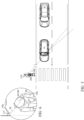
- Fig. 1 is a top view of a vehicle and pedestrian.
- a vehicle 14 is disposed near a passage 53, and a pedestrian 28 has not yet started crossing the road.
- the condition for allowing driving is that the driver views pedestrian 28, and as well pedestrian 28 views the driver.
- the driver's head is directed towards pedestrian 28B and the pedestrian's head is directed towards the driver's head.
- Fig. 2 depicts the determination that the driver's head is directed towards pedestrian 28 and that the pedestrian's head is directed towards the driver.
- the driver's head is directed towards line 54A being right angled 56 to the line 58 between eye 50A and 50B.
- the determination of the pedestrian's view 34B is line 54B surrounded by angle 60B, being equal to angle 60A.
- the system may produce a request to the driver to allow pedestrian 28 to cross the road.
- Fig. 3 depicts the determination that the driver's head is not directed towards pedestrian 28 and that the pedestrian's head is directed towards the driver.
- Fig. 4 is a schematic top view describing the determination that the driver's head is directed towards the pedestrian and that the pedestrian's head is directed towards the driver's head.
- Nose 20 of driver's head 16A is directed to line 54A being right angled 56 to the line 58 between eye 50A and 50B.
- camera 12A is disposed above head 16A of the driver, for capturing nose 20 thereof.
- Camera 12A is accompanied by an electronic compass 51, for determining absolute angle 57A of nose 20, being in the example 315 degrees in relation to the absolute North, thus to convert non-absolute angle obtained from camera 12A to absolute angle.
- Nose 20 of the pedestrian's head 16B is directed to line 54B.
- Camera 12B is disposed above head 16B of the pedestrian for capturing nose 20 thereof for determining absolute angle 57B thereof, being in the example 135 degrees in relation to the absolute North.
- Fig. 5 is an example of Fig. 4 .
- Fig. 6 enlarges the pedestrian of Fig. 5 .
- the meeting lines 54A and 54B is not accurate, but rather considers the driver's angle of view surrounding line 54A and the pedestrian's angle of view surrounding line 54B.
- the term "above” regarding disposition of the camera above the head need not be accurate, and may include horizontal shifting, as shown in Fig. 6 .
- cameras 12A and 12B may not require entire image processing of the face, but rather may isolate the noses shape as protruding.
- cameras 12A and 12B may include heat sensors only, since the optical resolution requiring the capturing the nose's angle is resolution.
- Fig. 7 is a side view showing the camera's disposition above the driver's head, for determining the nose's angle.
- Camera 12A is disposed at the ceiling of the vehicle's compartment, and being directed downwards 55A, for capturing driver's nose 20.
- An additional camera 12C may be directed horizontally (55B), for capturing the body of pedestrian 28B and for determining direction 54C thereof.
- Camera 12C directed horizontally may as well capture eyes or spectacles of pedestrian 28B, for determining angle 57B of the pedestrian's head and eyes.
- Camera 12C may include illumination or image heat for capturing at night.
- Controller 59 which may be installed to the vehicle collects data from cameras 12A, 12B and 12C, and may further collect data from the brake circuit 68 inputted by the brake pedal 66 of the vehicle.
- reporting means 64 which may be visual or vocal, which may be installed to the vehicle, announces prohibition both to the driver and to the pedestrian to advance. Once controller 59 determines that eyes of the driver and of the pedestrian are directed one towards the other, and that brake circuit 68 inputs that the driver has braked brake pedal 66, then reporting means 64 may allow the pedestrian to advance.
- horizontal direction 54A of the driver's nose 20 must be the horizontal direction 54C for which camera 12C captures pedestrian 28B.
- Fig. 8 is a side view showing the camera's disposition above the pedestrian's head, for determining the nose's angle.
- a camera 12B may be disposed sufficiently high for capturing noses of all pedestrians; or a plurality of cameras 12B may be disposed above passage 53.
- reporting means 64 may allow the driver or to the pedestrian to advance.
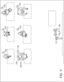
- Fig. 9 is a top view of the apparatus applied for a lecturer and students.
- the apparatus may be applied for examining a teacher or lecturer regarding the concentration being level of listening thereto, via the level of eye contact between the lecturer and the students.
- the invention is directed to a gaze direction determination apparatus (10), including at least one camera for determining gaze direction of at least one person, the apparatus characterized by including:
- a gaze direction determination apparatus including at least one camera for determining gaze direction of at least one person, the apparatus characterized by including:
Landscapes
- Engineering & Computer Science (AREA)
- Physics & Mathematics (AREA)
- General Physics & Mathematics (AREA)
- Theoretical Computer Science (AREA)
- Mechanical Engineering (AREA)
- Human Computer Interaction (AREA)
- General Engineering & Computer Science (AREA)
- Multimedia (AREA)
- Computer Vision & Pattern Recognition (AREA)
- Signal Processing (AREA)
- Acoustics & Sound (AREA)
- Traffic Control Systems (AREA)
- Fittings On The Vehicle Exterior For Carrying Loads, And Devices For Holding Or Mounting Articles (AREA)
Abstract
Description
- The invention relates to the field of gaze direction determination for traffic and other uses.
- When a pedestrian intends to cross a road, for example, at a crosswalk, and sees a vehicle approaching, he does not know whether the vehicle intends to stop before the pedestrian crossing or not.
- This can cause accidents and injuries to the body and property.
- There is a long felt need to provide a solution to the above-mentioned and other problems of the prior art.
- A gaze direction determination apparatus, including:
- a first camera, for capturing the nose thereof from above the nose;
- a second camera for capturing at least a second person.
- Embodiments, features, and aspects of the invention are described herein in conjunction with the following drawings:
-
Fig. 1 is a top view of a vehicle and pedestrian. -
Fig. 2 depicts the determination that the driver's head is directed towards pedestrian 28 and that the pedestrian's head is directed towards the driver. -
Fig. 3 depicts the determination that the driver's head is not directed towards pedestrian 28 and that the pedestrian's head is directed towards the driver. -
Fig. 4 is a schematic top view describing the determination that the driver's head is directed towards the pedestrian and that the pedestrian's head is directed towards the driver's head. -
Fig. 5 is an example ofFig. 4 . -
Fig. 6 enlarges the pedestrian ofFig. 5 . -
Fig. 7 is a side view showing the camera's disposition above the driver's head, for determining the nose's angle. -
Fig. 8 is a side view showing the camera's disposition above the pedestrian's head, for determining the nose's angle. -
Fig. 9 is a top view of the apparatus applied for a lecturer and students. - The drawings are not necessarily drawn to scale.
- The invention will be understood from the following detailed description of embodiments of the invention, which are meant to be descriptive and not limiting. For the sake of brevity, some well-known features are not described in detail.
- The reference numbers have been used to point out elements in the embodiments described and illustrated herein, in order to facilitate the understanding of the invention. They are meant to be merely illustrative, and not limiting. Also, the foregoing embodiments of the invention have been described and illustrated in conjunction with systems and methods thereof, which are meant to be merely illustrative, and not limiting.
-
Fig. 1 is a top view of a vehicle and pedestrian. - Suppose a
vehicle 14 is disposed near apassage 53, and a pedestrian 28 has not yet started crossing the road. - The condition for allowing driving is that the driver views pedestrian 28, and as well pedestrian 28 views the driver.
- This is determined by determining the angle of the
head 16A of the driver bycamera 12A, and by determining the angle of thehead 16B of pedestrian 28 bycamera 12B. - In the example of
Fig. 1 , the driver's head is directed towardspedestrian 28B and the pedestrian's head is directed towards the driver's head. -
Fig. 2 depicts the determination that the driver's head is directed towards pedestrian 28 and that the pedestrian's head is directed towards the driver. - The driver's head is directed towards
line 54A being right angled 56 to theline 58 betweeneye - Referring again to
Fig. 1 , even thoughline 54A misses pedestrian 28, the driver'sview 34A isangle 60A surrounding line 54A, thus the driver indeed views pedestrian 28. - The determination of the pedestrian's
view 34B isline 54B surrounded byangle 60B, being equal toangle 60A. - Upon the determining that the driver views pedestrian 28, and that pedestrian 28 views the driver, the system may produce a request to the driver to allow pedestrian 28 to cross the road.
-
Fig. 3 depicts the determination that the driver's head is not directed towards pedestrian 28 and that the pedestrian's head is directed towards the driver. - In this case neither the driver, nor pedestrian 28 is allowed to advance.
-
Fig. 4 is a schematic top view describing the determination that the driver's head is directed towards the pedestrian and that the pedestrian's head is directed towards the driver's head. -
Nose 20 of driver'shead 16A is directed toline 54A being right angled 56 to theline 58 betweeneye camera 12A is disposed abovehead 16A of the driver, for capturingnose 20 thereof.Camera 12A is accompanied by anelectronic compass 51, for determiningabsolute angle 57A ofnose 20, being in the example 315 degrees in relation to the absolute North, thus to convert non-absolute angle obtained fromcamera 12A to absolute angle. -
Nose 20 of the pedestrian'shead 16B is directed toline 54B.Camera 12B is disposed abovehead 16B of the pedestrian for capturingnose 20 thereof for determiningabsolute angle 57B thereof, being in the example 135 degrees in relation to the absolute North. -
Fig. 5 is an example ofFig. 4 . -
Fig. 6 enlarges the pedestrian ofFig. 5 . - The 315 degrees of
line 54A, and 135 degrees ofline 54B meet the same line, since the difference therebetween is 315-135=180 degrees, expressing thatline 54A of one nose is directed towardsline 54B of the other nose. This meeting oflines - The
meeting lines view surrounding line 54A and the pedestrian's angle ofview surrounding line 54B. - Thus, and referring again to
Fig. 1 , even thoughline 54A slightly missesline 54B, the driver's angle ofview surrounding line 54A and the pedestrian's angle ofview surrounding line 54B should be considered to determine that the driver yet views pedestrian 28. - The term "above" regarding disposition of the camera above the head need not be accurate, and may include horizontal shifting, as shown in
Fig. 6 . - Capturing of
noses 20 from above simplifies the angles determination and the software calculations therefor. Thus,cameras cameras -
Fig. 7 is a side view showing the camera's disposition above the driver's head, for determining the nose's angle. - Camera 12A is disposed at the ceiling of the vehicle's compartment, and being directed downwards 55A, for capturing driver's
nose 20. - An
additional camera 12C may be directed horizontally (55B), for capturing the body ofpedestrian 28B and for determiningdirection 54C thereof. -
Camera 12C directed horizontally may as well capture eyes or spectacles ofpedestrian 28B, for determiningangle 57B of the pedestrian's head and eyes.Camera 12C may include illumination or image heat for capturing at night. -
Controller 59 which may be installed to the vehicle collects data fromcameras brake circuit 68 inputted by thebrake pedal 66 of the vehicle. - While
controller 59 determines that eyes of the driver and of the pedestrian are not directed one towards the other, reporting means 64, which may be visual or vocal, which may be installed to the vehicle, announces prohibition both to the driver and to the pedestrian to advance. Oncecontroller 59 determines that eyes of the driver and of the pedestrian are directed one towards the other, and thatbrake circuit 68 inputs that the driver has brakedbrake pedal 66, then reportingmeans 64 may allow the pedestrian to advance. - Referring again to
Fig. 4 ,horizontal direction 54A of the driver'snose 20 must be thehorizontal direction 54C for whichcamera 12C captures pedestrian 28B. -
Fig. 8 is a side view showing the camera's disposition above the pedestrian's head, for determining the nose's angle. - Rather than
camera 12C attached tovehicle 14 for capturing the eyes ofpedestrian 28B, acamera 12B may be disposed sufficiently high for capturing noses of all pedestrians; or a plurality ofcameras 12B may be disposed abovepassage 53. - Upon determining that noses of the driver and pedestrian are directed one towards the other, reporting means 64, which may be attached to the vehicle, may allow the driver or to the pedestrian to advance.
-
Fig. 9 is a top view of the apparatus applied for a lecturer and students. - The apparatus may be applied for examining a teacher or lecturer regarding the concentration being level of listening thereto, via the level of eye contact between the lecturer and the students.
- Thus, in one aspect, the invention is directed to a gaze direction determination apparatus (10), including at least one camera for determining gaze direction of at least one person, the apparatus characterized by including:
In the figures and/or description herein, the following reference numerals (Reference Signs List) have been mentioned: - numeral 10 denotes the according to one embodiment of the invention;
- numeral 10 denotes the traffic allowance system according to one embodiment of the invention;
- 12A,12B,12C: cameras;
- 14: vehicle;
- 16A: driver's or lecturer's head;
- 16B: pedestrian's or student's head;
- 28A: driver or lecturer or another person;
- 28B: pedestrian or student or another person;
- 34A: driver's view;
- 34B: pedestrian's view;
- 50A,50B: drivers' eyes;
- 51: compass;
- 52A,52B: pedestrian's eyes;
- 53: passage;
- 54A: center of driver's view as determined by
camera 12A; - 54B: center of pedestrian's view as determined by
camera 12B; - 54C: direction of
pedestrian 28B in relation todriver 28A, as determined bycamera 12C; - 55A: vertical directing of
cameras - 55B: horizontal directing of
camera 12C; - 56: right angle;
- 57A: angle in relation to the absolute North, of
nose 20 of driver'shead 16A; - 57B: angle in relation to the absolute North, of
nose 20 of pedestrian'shead 16B; - 58: line between drivers' eyes;
- 59: controller including image processor;
- 60A: angle surrounding driver's center of view;
- 60B: angle surrounding pedestrian's center of view;
- 61: horizontal angle range of
camera 12C; - 64: reporting means, being visual or vocal;
- 66: brake pedal;
- 68: brake circuit;
- The foregoing description and illustrations of the embodiments of the invention have been presented for the purpose of illustration, and are not intended to be exhaustive or to limit the invention to the above description in any form.
- Any term that has been defined above and used in the claims, should be interpreted according to this definition.
- The reference numbers in the claims are not a part of the claims, but rather used for facilitating the reading thereof. These reference numbers should not be interpreted as limiting the claims in any form.
Claims (9)
- A gaze direction determination apparatus (10), including at least one camera for determining gaze direction of at least one person,
said apparatus characterized by comprising:- a first camera (12A) for capturing a head (16A) of a first person (28A);- at least a second camera (12B,12C) for capturing at least a head (16B) of at least a second person (28B); and- a controller (59) for processing captures of said first (12A) and said at least second cameras (12B,12C),for determining human communication in case determining from said captures' processing that eyes (50A,50B) of said first person (28A) and eyes of said at least second person (28B) are horizontally directed one (54A) towards the other (54B). - The apparatus according to claim 1, further comprising- reporting means (64),wherein said first person (28A) comprises a driver within a vehicle (14), and said at least second person (28B) comprises at least one pedestrian, wherein in case of said determination that the eyes (50A,50B) of said first person (28A) and the eyes of said at least second person (28B) are horizontally directed one (54A) towards the other (54B), and thata brake circuit (68) of the vehicle (14) inputs that the driver has braked a brake pedal (66) of the vehicle (14),then said controller (59) is configured to control said reporting means (64) to announce advancing allowance to said pedestrian.
- The gaze direction determination apparatus (10) according to claim 1,wherein said first camera (12A) is installed above said first person (28A) and is directed vertically downwards (55A), for capturing a nose (20) thereof from above said nose,thereby determining a horizontal angle (57A) of said nose, for applying said determining that the eyes (50A,50B) of said first person (28A) are horizontally directed to the eyes of said at least second person (28B).
- The gaze direction determination apparatus (10) according to claim 3, wherein said at least second camera (12B) is installed above said at least second person (28B) and is directed vertically downwards (55A), for capturing at least one nose (20) of said at least second person from above said second person's nose,
thereby said determining human communication is only in case said nose (20) of said first person (28A) as captured from above by said first camera (12A), and said nose (20) of said at least second person (28B) as captured from above by said at least second camera (12B), are horizontally directed one (54A) towards the other (54B). - The gaze direction determination apparatus (10) according to claim 3, wherein said at least second camera (12C) is directed vertically (55B) towards said at least second person (28B).
- The apparatus of claim 3, further comprising:- a compass (51) for converting said determined horizontal angle (57A) to be absolute.
- The apparatus of claim 3, further comprising:- a third camera (12C) for being installed near said first person (28A) and being directed horizontally (55B), for capturing a body of said at least said second person (28B),wherein said horizontal angle (57A) of said nose, and a horizontal direction (54C) of the least the second person (28B) as captured by the third camera (12C), must be equal for applying said determining that the eyes (50A,50B) of said first person (28A) are horizontally directed to the eyes of said at least second person (28B).
- The apparatus according to claim 4, wherein said installation of said first camera above said first person comprises installing said first camera within a room above a lecturer being said first person, and
wherein said installation of said at least second camera above said at least second person comprises installing said at least second camera within said room above students being said at least said second person. - The apparatus according to claim 3, wherein said first camera comprises heat sensors, for sensing locations of heat distributed from said nose (20).
Priority Applications (2)
| Application Number | Priority Date | Filing Date | Title |
|---|---|---|---|
| EP22155499.1A EP4224288B1 (en) | 2022-02-07 | 2022-02-07 | Gaze direction determination apparatus |
| US18/102,728 US12094156B2 (en) | 2022-02-07 | 2023-01-29 | Gaze direction determination apparatus |
Applications Claiming Priority (1)
| Application Number | Priority Date | Filing Date | Title |
|---|---|---|---|
| EP22155499.1A EP4224288B1 (en) | 2022-02-07 | 2022-02-07 | Gaze direction determination apparatus |
Publications (3)
| Publication Number | Publication Date |
|---|---|
| EP4224288A1 true EP4224288A1 (en) | 2023-08-09 |
| EP4224288B1 EP4224288B1 (en) | 2025-12-17 |
| EP4224288C0 EP4224288C0 (en) | 2025-12-17 |
Family
ID=80445814
Family Applications (1)
| Application Number | Title | Priority Date | Filing Date |
|---|---|---|---|
| EP22155499.1A Active EP4224288B1 (en) | 2022-02-07 | 2022-02-07 | Gaze direction determination apparatus |
Country Status (2)
| Country | Link |
|---|---|
| US (1) | US12094156B2 (en) |
| EP (1) | EP4224288B1 (en) |
Citations (3)
| Publication number | Priority date | Publication date | Assignee | Title |
|---|---|---|---|---|
| US5686942A (en) * | 1994-12-01 | 1997-11-11 | National Semiconductor Corporation | Remote computer input system which detects point source on operator |
| US20090022368A1 (en) * | 2006-03-15 | 2009-01-22 | Omron Corporation | Monitoring device, monitoring method, control device, control method, and program |
| US10821886B1 (en) * | 2019-08-13 | 2020-11-03 | International Business Machines Corporation | Sensor-based acknowledgments between road traffic participants |
Family Cites Families (12)
| Publication number | Priority date | Publication date | Assignee | Title |
|---|---|---|---|---|
| US10769799B2 (en) * | 2018-08-24 | 2020-09-08 | Ford Global Technologies, Llc | Foreground detection |
| MX2021003177A (en) * | 2018-09-21 | 2021-05-27 | Nissan Motor | Reserved vehicle control method, reserved vehicle control device, and reserved vehicle control system. |
| US10780897B2 (en) * | 2019-01-31 | 2020-09-22 | StradVision, Inc. | Method and device for signaling present driving intention of autonomous vehicle to humans by using various V2X-enabled application |
| KR20210134634A (en) * | 2019-03-29 | 2021-11-10 | 인텔 코포레이션 | autonomous vehicle system |
| US10894512B2 (en) * | 2019-04-11 | 2021-01-19 | Gregory J. Phillips | Side-facing side view mirror brake lights |
| JP7402796B2 (en) * | 2019-06-17 | 2023-12-21 | グーグル エルエルシー | Method, computing device, computing system, computer program, and vehicle for determining vehicle occupant involvement using three-dimensional gaze vectors |
| JP7283377B2 (en) * | 2019-12-24 | 2023-05-30 | 株式会社オートネットワーク技術研究所 | Wireless communication device, wireless communication system and wireless communication method |
| US11720170B2 (en) * | 2019-12-26 | 2023-08-08 | Stmicroelectronics, Inc. | Method, device, and system of measuring eye convergence angle |
| US11688184B2 (en) * | 2020-06-17 | 2023-06-27 | Toyota Motor Engineering & Manufacturing North America, Inc. | Driving automation external communication location change |
| US11518305B2 (en) * | 2020-10-08 | 2022-12-06 | Harman International Industries, Incorporated | Techniques for generating vehicle-to-pedestrian (V2P) communications based on driver monitoring |
| US20230059370A1 (en) * | 2021-08-18 | 2023-02-23 | Waymo Llc | Gaze and awareness prediction using a neural network model |
| US20230386326A1 (en) * | 2022-05-26 | 2023-11-30 | Ford Global Technologies, Llc | Systems and methods for detecting pedestrians with crosswalking or jaywalking intent |
-
2022
- 2022-02-07 EP EP22155499.1A patent/EP4224288B1/en active Active
-
2023
- 2023-01-29 US US18/102,728 patent/US12094156B2/en active Active
Patent Citations (3)
| Publication number | Priority date | Publication date | Assignee | Title |
|---|---|---|---|---|
| US5686942A (en) * | 1994-12-01 | 1997-11-11 | National Semiconductor Corporation | Remote computer input system which detects point source on operator |
| US20090022368A1 (en) * | 2006-03-15 | 2009-01-22 | Omron Corporation | Monitoring device, monitoring method, control device, control method, and program |
| US10821886B1 (en) * | 2019-08-13 | 2020-11-03 | International Business Machines Corporation | Sensor-based acknowledgments between road traffic participants |
Also Published As
| Publication number | Publication date |
|---|---|
| EP4224288B1 (en) | 2025-12-17 |
| US20230252668A1 (en) | 2023-08-10 |
| EP4224288C0 (en) | 2025-12-17 |
| US12094156B2 (en) | 2024-09-17 |
Similar Documents
| Publication | Publication Date | Title |
|---|---|---|
| CN112486160B (en) | Vehicle Remote Indicator System | |
| WO2022119079A1 (en) | Crossroad danger warning system based on situation prediction | |
| EP1961613B1 (en) | Driving support method and driving support device | |
| JP6891926B2 (en) | Vehicle systems, methods performed on vehicle systems, and driver assistance systems | |
| KR101241623B1 (en) | Crime prevention insert tpye traffic safety system on crosswalk | |
| KR20110113185A (en) | Method and apparatus for determining effective lane marking | |
| JPWO2019181284A1 (en) | Information processing equipment, mobile devices, and methods, and programs | |
| WO2017217737A1 (en) | Enforcement cctv system, against illegal parking and stopping, by means of tracking moving vehicles | |
| US8305431B2 (en) | Device intended to support the driving of a motor vehicle comprising a system capable of capturing stereoscopic images | |
| CN112339771B (en) | Parking process display method and device and vehicle | |
| CN114930264A (en) | Method for remote-controlled driving of a motor vehicle comprising a remote-controlled operator, computer program product and remote-controlled driving system | |
| JP2000163685A (en) | Traffic flow monitoring system | |
| US11127299B2 (en) | Traffic allowance method | |
| KR102415620B1 (en) | Variable vehicle speed warning system including pedestrian determination system | |
| EP4224288B1 (en) | Gaze direction determination apparatus | |
| CN110727269B (en) | Vehicle control method and related product | |
| CN120340306A (en) | Vehicle projection warning method, device, equipment, system, vehicle, storage medium and program product | |
| JP7522577B2 (en) | Parking lot camera system, information terminal and computer program | |
| US8818623B2 (en) | Method and system for providing image information | |
| JP2003256987A (en) | Intersection signal guidance assistance system | |
| KR101687741B1 (en) | Active advertisement system and control method thereof based on traffic signal | |
| KR102720235B1 (en) | Parking guide system based on cameras and method for processing thereof | |
| CN108688651A (en) | Method and system for motor vehicles | |
| KR102892834B1 (en) | Intelligent pedestrian safety system based on C-V2X and CCTV | |
| KR102630264B1 (en) | System, method and computer program for providing guidance information of intersection |
Legal Events
| Date | Code | Title | Description |
|---|---|---|---|
| PUAI | Public reference made under article 153(3) epc to a published international application that has entered the european phase |
Free format text: ORIGINAL CODE: 0009012 |
|
| STAA | Information on the status of an ep patent application or granted ep patent |
Free format text: STATUS: THE APPLICATION HAS BEEN PUBLISHED |
|
| AK | Designated contracting states |
Kind code of ref document: A1 Designated state(s): AL AT BE BG CH CY CZ DE DK EE ES FI FR GB GR HR HU IE IS IT LI LT LU LV MC MK MT NL NO PL PT RO RS SE SI SK SM TR |
|
| STAA | Information on the status of an ep patent application or granted ep patent |
Free format text: STATUS: REQUEST FOR EXAMINATION WAS MADE |
|
| 17P | Request for examination filed |
Effective date: 20240207 |
|
| RBV | Designated contracting states (corrected) |
Designated state(s): AL AT BE BG CH CY CZ DE DK EE ES FI FR GB GR HR HU IE IS IT LI LT LU LV MC MK MT NL NO PL PT RO RS SE SI SK SM TR |
|
| STAA | Information on the status of an ep patent application or granted ep patent |
Free format text: STATUS: EXAMINATION IS IN PROGRESS |
|
| 17Q | First examination report despatched |
Effective date: 20240725 |
|
| RIC1 | Information provided on ipc code assigned before grant |
Ipc: B60Q 1/50 20060101ALI20250207BHEP Ipc: B60Q 5/00 20060101ALI20250207BHEP Ipc: B60Q 9/00 20060101ALI20250207BHEP Ipc: G06F 3/01 20060101AFI20250207BHEP |
|
| GRAP | Despatch of communication of intention to grant a patent |
Free format text: ORIGINAL CODE: EPIDOSNIGR1 |
|
| STAA | Information on the status of an ep patent application or granted ep patent |
Free format text: STATUS: GRANT OF PATENT IS INTENDED |
|
| INTG | Intention to grant announced |
Effective date: 20250708 |
|
| GRAS | Grant fee paid |
Free format text: ORIGINAL CODE: EPIDOSNIGR3 |
|
| GRAA | (expected) grant |
Free format text: ORIGINAL CODE: 0009210 |
|
| STAA | Information on the status of an ep patent application or granted ep patent |
Free format text: STATUS: THE PATENT HAS BEEN GRANTED |
|
| AK | Designated contracting states |
Kind code of ref document: B1 Designated state(s): AL AT BE BG CH CY CZ DE DK EE ES FI FR GB GR HR HU IE IS IT LI LT LU LV MC MK MT NL NO PL PT RO RS SE SI SK SM TR |
|
| REG | Reference to a national code |
Ref country code: CH Ref legal event code: F10 Free format text: ST27 STATUS EVENT CODE: U-0-0-F10-F00 (AS PROVIDED BY THE NATIONAL OFFICE) Effective date: 20251217 Ref country code: GB Ref legal event code: FG4D |
|
| REG | Reference to a national code |
Ref country code: DE Ref legal event code: R096 Ref document number: 602022026837 Country of ref document: DE |
|
| U01 | Request for unitary effect filed |
Effective date: 20260109 |
|
| U07 | Unitary effect registered |
Designated state(s): AT BE BG DE DK EE FI FR IT LT LU LV MT NL PT RO SE SI Effective date: 20260115 |
|
| REG | Reference to a national code |
Ref country code: CH Ref legal event code: U11 Free format text: ST27 STATUS EVENT CODE: U-0-0-U10-U11 (AS PROVIDED BY THE NATIONAL OFFICE) Effective date: 20260302 |
|
| U20 | Renewal fee for the european patent with unitary effect paid |
Year of fee payment: 5 Effective date: 20260302 |
|
| PGFP | Annual fee paid to national office [announced via postgrant information from national office to epo] |
Ref country code: GB Payment date: 20260302 Year of fee payment: 5 |
|
| PG25 | Lapsed in a contracting state [announced via postgrant information from national office to epo] |
Ref country code: NO Free format text: LAPSE BECAUSE OF FAILURE TO SUBMIT A TRANSLATION OF THE DESCRIPTION OR TO PAY THE FEE WITHIN THE PRESCRIBED TIME-LIMIT Effective date: 20260317 |
|
| PG25 | Lapsed in a contracting state [announced via postgrant information from national office to epo] |
Ref country code: HR Free format text: LAPSE BECAUSE OF FAILURE TO SUBMIT A TRANSLATION OF THE DESCRIPTION OR TO PAY THE FEE WITHIN THE PRESCRIBED TIME-LIMIT Effective date: 20251217 |
|
| PGFP | Annual fee paid to national office [announced via postgrant information from national office to epo] |
Ref country code: AT Payment date: 20260301 Year of fee payment: 5 |
|
| PG25 | Lapsed in a contracting state [announced via postgrant information from national office to epo] |
Ref country code: RS Free format text: LAPSE BECAUSE OF FAILURE TO SUBMIT A TRANSLATION OF THE DESCRIPTION OR TO PAY THE FEE WITHIN THE PRESCRIBED TIME-LIMIT Effective date: 20260317 |
|
| PGFP | Annual fee paid to national office [announced via postgrant information from national office to epo] |
Ref country code: CH Payment date: 20260302 Year of fee payment: 5 |