EP4224136A1 - Temperature derivation method for oil film, temperature derivation device, and program - Google Patents
Temperature derivation method for oil film, temperature derivation device, and program Download PDFInfo
- Publication number
- EP4224136A1 EP4224136A1 EP21875465.3A EP21875465A EP4224136A1 EP 4224136 A1 EP4224136 A1 EP 4224136A1 EP 21875465 A EP21875465 A EP 21875465A EP 4224136 A1 EP4224136 A1 EP 4224136A1
- Authority
- EP
- European Patent Office
- Prior art keywords
- lubricant
- temperature
- oil film
- relaxation time
- derivation
- Prior art date
- Legal status (The legal status is an assumption and is not a legal conclusion. Google has not performed a legal analysis and makes no representation as to the accuracy of the status listed.)
- Granted
Links
Images


Classifications
-
- G—PHYSICS
- G01—MEASURING; TESTING
- G01K—MEASURING TEMPERATURE; MEASURING QUANTITY OF HEAT; THERMALLY-SENSITIVE ELEMENTS NOT OTHERWISE PROVIDED FOR
- G01K7/00—Measuring temperature based on the use of electric or magnetic elements directly sensitive to heat ; Power supply therefor, e.g. using thermoelectric elements
- G01K7/34—Measuring temperature based on the use of electric or magnetic elements directly sensitive to heat ; Power supply therefor, e.g. using thermoelectric elements using capacitative elements
- G01K7/343—Measuring temperature based on the use of electric or magnetic elements directly sensitive to heat ; Power supply therefor, e.g. using thermoelectric elements using capacitative elements the dielectric constant of which is temperature dependant
-
- G—PHYSICS
- G01—MEASURING; TESTING
- G01K—MEASURING TEMPERATURE; MEASURING QUANTITY OF HEAT; THERMALLY-SENSITIVE ELEMENTS NOT OTHERWISE PROVIDED FOR
- G01K11/00—Measuring temperature based upon physical or chemical changes not covered by groups G01K3/00, G01K5/00, G01K7/00 or G01K9/00
-
- F—MECHANICAL ENGINEERING; LIGHTING; HEATING; WEAPONS; BLASTING
- F16—ENGINEERING ELEMENTS AND UNITS; GENERAL MEASURES FOR PRODUCING AND MAINTAINING EFFECTIVE FUNCTIONING OF MACHINES OR INSTALLATIONS; THERMAL INSULATION IN GENERAL
- F16C—SHAFTS; FLEXIBLE SHAFTS; ELEMENTS OR CRANKSHAFT MECHANISMS; ROTARY BODIES OTHER THAN GEARING ELEMENTS; BEARINGS
- F16C19/00—Bearings with rolling contact, for exclusively rotary movement
- F16C19/02—Bearings with rolling contact, for exclusively rotary movement with bearing balls essentially of the same size in one or more circular rows
-
- F—MECHANICAL ENGINEERING; LIGHTING; HEATING; WEAPONS; BLASTING
- F16—ENGINEERING ELEMENTS AND UNITS; GENERAL MEASURES FOR PRODUCING AND MAINTAINING EFFECTIVE FUNCTIONING OF MACHINES OR INSTALLATIONS; THERMAL INSULATION IN GENERAL
- F16C—SHAFTS; FLEXIBLE SHAFTS; ELEMENTS OR CRANKSHAFT MECHANISMS; ROTARY BODIES OTHER THAN GEARING ELEMENTS; BEARINGS
- F16C19/00—Bearings with rolling contact, for exclusively rotary movement
- F16C19/22—Bearings with rolling contact, for exclusively rotary movement with bearing rollers essentially of the same size in one or more circular rows, e.g. needle bearings
-
- F—MECHANICAL ENGINEERING; LIGHTING; HEATING; WEAPONS; BLASTING
- F16—ENGINEERING ELEMENTS AND UNITS; GENERAL MEASURES FOR PRODUCING AND MAINTAINING EFFECTIVE FUNCTIONING OF MACHINES OR INSTALLATIONS; THERMAL INSULATION IN GENERAL
- F16C—SHAFTS; FLEXIBLE SHAFTS; ELEMENTS OR CRANKSHAFT MECHANISMS; ROTARY BODIES OTHER THAN GEARING ELEMENTS; BEARINGS
- F16C19/00—Bearings with rolling contact, for exclusively rotary movement
- F16C19/52—Bearings with rolling contact, for exclusively rotary movement with devices affected by abnormal or undesired conditions
- F16C19/525—Bearings with rolling contact, for exclusively rotary movement with devices affected by abnormal or undesired conditions related to temperature and heat, e.g. insulation
-
- F—MECHANICAL ENGINEERING; LIGHTING; HEATING; WEAPONS; BLASTING
- F16—ENGINEERING ELEMENTS AND UNITS; GENERAL MEASURES FOR PRODUCING AND MAINTAINING EFFECTIVE FUNCTIONING OF MACHINES OR INSTALLATIONS; THERMAL INSULATION IN GENERAL
- F16C—SHAFTS; FLEXIBLE SHAFTS; ELEMENTS OR CRANKSHAFT MECHANISMS; ROTARY BODIES OTHER THAN GEARING ELEMENTS; BEARINGS
- F16C33/00—Parts of bearings; Special methods for making bearings or parts thereof
- F16C33/30—Parts of ball or roller bearings
- F16C33/66—Special parts or details in view of lubrication
- F16C33/6603—Special parts or details in view of lubrication with grease as lubricant
- F16C33/6633—Grease properties or compositions, e.g. rheological properties
-
- F—MECHANICAL ENGINEERING; LIGHTING; HEATING; WEAPONS; BLASTING
- F16—ENGINEERING ELEMENTS AND UNITS; GENERAL MEASURES FOR PRODUCING AND MAINTAINING EFFECTIVE FUNCTIONING OF MACHINES OR INSTALLATIONS; THERMAL INSULATION IN GENERAL
- F16C—SHAFTS; FLEXIBLE SHAFTS; ELEMENTS OR CRANKSHAFT MECHANISMS; ROTARY BODIES OTHER THAN GEARING ELEMENTS; BEARINGS
- F16C33/00—Parts of bearings; Special methods for making bearings or parts thereof
- F16C33/30—Parts of ball or roller bearings
- F16C33/66—Special parts or details in view of lubrication
- F16C33/6637—Special parts or details in view of lubrication with liquid lubricant
- F16C33/6688—Lubricant compositions or properties, e.g. viscosity
-
- G—PHYSICS
- G01—MEASURING; TESTING
- G01K—MEASURING TEMPERATURE; MEASURING QUANTITY OF HEAT; THERMALLY-SENSITIVE ELEMENTS NOT OTHERWISE PROVIDED FOR
- G01K1/00—Details of thermometers not specially adapted for particular types of thermometer
- G01K1/14—Supports; Fastening devices; Arrangements for mounting thermometers in particular locations
-
- G—PHYSICS
- G01—MEASURING; TESTING
- G01K—MEASURING TEMPERATURE; MEASURING QUANTITY OF HEAT; THERMALLY-SENSITIVE ELEMENTS NOT OTHERWISE PROVIDED FOR
- G01K13/00—Thermometers specially adapted for specific purposes
- G01K13/02—Thermometers specially adapted for specific purposes for measuring temperature of moving fluids or granular materials capable of flow
- G01K13/026—Thermometers specially adapted for specific purposes for measuring temperature of moving fluids or granular materials capable of flow of moving liquids
-
- G—PHYSICS
- G01—MEASURING; TESTING
- G01M—TESTING STATIC OR DYNAMIC BALANCE OF MACHINES OR STRUCTURES; TESTING OF STRUCTURES OR APPARATUS, NOT OTHERWISE PROVIDED FOR
- G01M13/00—Testing of machine parts
- G01M13/04—Bearings
-
- F—MECHANICAL ENGINEERING; LIGHTING; HEATING; WEAPONS; BLASTING
- F16—ENGINEERING ELEMENTS AND UNITS; GENERAL MEASURES FOR PRODUCING AND MAINTAINING EFFECTIVE FUNCTIONING OF MACHINES OR INSTALLATIONS; THERMAL INSULATION IN GENERAL
- F16C—SHAFTS; FLEXIBLE SHAFTS; ELEMENTS OR CRANKSHAFT MECHANISMS; ROTARY BODIES OTHER THAN GEARING ELEMENTS; BEARINGS
- F16C2233/00—Monitoring condition, e.g. temperature, load, vibration
Definitions
- the conditions around the lubricant include a temperature of an oil film due to the lubricant.
- a film thickness of a lubricant and a metal contact ratio can be derived, the temperature of the lubricant is not measured.
- infrared methods such as thermography require constant thermal radiation of the object.
- the temperature diagnosis method by means of thermochromism, or the like, the object needs to exist in a place where the object can be diagnosed.
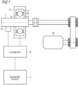
- Fig. 1 is a schematic configuration diagram illustrating an example of the overall configuration when performing diagnosis with a diagnosis device 1 according to this embodiment.
- a bearing device 2 to which a temperature derivation method according to this embodiment is applied and the diagnosis device 1 performing temperature derivation and diagnosis of an oil film.
- the configuration illustrated in Fig. 1 is an exemplary one, and a different configuration may be used according to a configuration of the bearing device 2 and the like.
- Fig. 1 illustrates a configuration in which the bearing device 2 includes one rolling bearing, the present invention is not limited thereto, and one bearing device 2 may include a plurality of rolling bearings.
- Figs. 2A and 2B there is a difference in the measurement results of the oil film due to the lubricant (bulk state) and the lubricant in the rolling bearing.
- the relaxation time ⁇ peak position moves to the high frequency side in the measurement result of the oil film due to the lubricant in the rolling bearing.
- the DC conductivity ⁇ 0 is higher in the measurement result of the oil film due to the lubricant in the rolling bearing.
- the reason for such a difference is that the temperature of the oil film in the rolling bearing rose above the outer ring temperature (here, 23°C) due to the rolling operation of the rolling bearing.
- Fig. 7 is a flowchart of a temperature detection process according to this embodiment. This processing is executed by the diagnosis device 1, and for example, a control device (not illustrated) included in the diagnosis device 1 reads a program for realizing the processing according to this embodiment from a storage device (not illustrated) and executes the program may realize this processing.
- a control device included in the diagnosis device 1 reads a program for realizing the processing according to this embodiment from a storage device (not illustrated) and executes the program may realize this processing.
- the diagnosis device 1 allows the motor 10 to start rotating the rotating shaft 7. Accordingly, the rotation of the inner ring 4 connected to the rotating shaft 7 is started. It is noted that the control of the motor 10 may be performed by a device other than the diagnosis device 1.
- the diagnosis device 1 acquires the impedance
- the oil film due to the lubricant in the rolling bearing has been described as an example, but the present invention is not limited thereto.
- the method according to the present invention can be applied to any substance that is used in a device and whose temperature is difficult to be directly detected and that causes dielectric relaxation, not limited to lubricants.
- the applicable device is not limited to rolling bearings, and the method according to the present invention can be applied to other rolling devices using substances that cause dielectric relaxation.
- lithium-based grease was used as an example of the lubricant, but the lubricant is not limited thereto.
- the method according to the present invention can also be applied to lubricants that cause dielectric relaxation.
- the present invention is not limited to the above-described embodiments, and those skilled in the art can make modifications and applications by combining the respective configurations of the embodiments with each other based on the description of the specification and well-known techniques, which are also contemplated by the present invention and falls within the scope of protection of the present invention.
Landscapes
- Engineering & Computer Science (AREA)
- General Engineering & Computer Science (AREA)
- Physics & Mathematics (AREA)
- General Physics & Mathematics (AREA)
- Mechanical Engineering (AREA)
- Power Engineering (AREA)
- Rolling Contact Bearings (AREA)
- Measuring Temperature Or Quantity Of Heat (AREA)
- Testing Of Devices, Machine Parts, Or Other Structures Thereof (AREA)
- Investigating Or Analyzing Materials By The Use Of Electric Means (AREA)
Abstract
Description
- The present invention relates to an oil film temperature derivation method, a temperature derivation device, and a program.
- In the related art, in bearing devices, a configuration in which a lubricant (for example, lubricating oil or grease) is used to lubricate rotation has been widely used. On the other hand, by periodically diagnosing a state of rotating parts such as bearing devices, damage and wear can be detected at an early stage to prevent failures of the rotating parts from occurring.
- The bearing device using a lubricant is required to appropriately detect the state related to the lubricant in order to diagnose the operating state. For example,
Patent Literature 1 discloses a method for detecting an oil film thickness of a lubricant and a metal contact ratio in a rolling device. - Patent Literature 1:
JP-A-2019-211317 - It is very useful to grasp conditions around a lubricant in a device such as a bearing device to prevent damage to a device. The conditions around the lubricant include a temperature of an oil film due to the lubricant. In a method of
Patent Literature 1, although a film thickness of a lubricant and a metal contact ratio can be derived, the temperature of the lubricant is not measured. When measuring the temperature of an oil film due to a lubricant whose temperature is expected to change, there are restrictions according to the installation position of a temperature sensor and control during measurement based on the measurement principle of the temperature sensor. For example, infrared methods such as thermography require constant thermal radiation of the object. In addition, in the temperature diagnosis method by means of thermochromism, or the like, the object needs to exist in a place where the object can be diagnosed. - In view of the above problems, an object of the present invention is to provide a method for easily deriving an oil film temperature of a lubricant in a device.
- In order to solve the above-described problems, the present invention has the following configuration. That is, there is provided a temperature derivation method for deriving an oil film temperature of a lubricant in a device, the temperature derivation method including:
- a measurement step of measuring a dielectric constant of the lubricant by applying an alternating voltage while changing a frequency to an electric circuit configured by the device;
- a derivation step of applying the dielectric constant measured in the measurement step to a theoretical formula to derive a relaxation time of the lubricant; and
- a calculation step of calculating the oil film temperature by using the relaxation time.
- In addition, another aspect of the present invention has the following configuration. That is, there is provided a temperature derivation device for detecting an oil film temperature of a lubricant in a device, the temperature derivation device including:
- a measurement unit measuring a dielectric constant of the lubricant by applying an alternating voltage while changing a frequency to an electric circuit configured by the device;
- a derivation unit applying the dielectric constant measured by the measurement unit to a theoretical formula to derive a relaxation time of the lubricant; and
- a calculation unit calculating the oil film temperature by using the relaxation time.
- In addition, another aspect of the present invention has the following configuration. That is, the program causing a computer to execute:
- a measurement step of measuring a dielectric constant of a lubricant in a device by applying an alternating voltage while changing a frequency to an electric circuit configured by the device;
- a derivation step of applying the dielectric constant measured in the measurement step to a theoretical formula to derive a relaxation time of the lubricant; and
- a calculation step of calculating an oil film temperature of the lubricant by using the relaxation time.
- According to the present invention, it is possible to provide a method for easily deriving the oil film temperature of a lubricant in a device.
-
-
Fig. 1 is a schematic diagram illustrating an example of a configuration of a device according to one embodiment of the present invention. -
Figs. 2A and 2B are diagrams illustrating a relationship between a frequency and a dielectric constant. -
Fig. 3 is a diagram illustrating a relationship between a relaxation time and an absolute temperature. -
Fig. 4 is a diagram illustrating derivation of parameters by fitting to a theoretical formula. -
Fig. 5 is a diagram illustrating a correlation between a temperature and a relaxation time. -
Fig. 6 is a diagram illustrating an example of a derivation result of an oil film temperature according to the present embodiment. -
Fig. 7 is a flowchart of processing when deriving a temperature according to one embodiment of the present invention. - Hereinafter, an aspect for implementing the present invention is described with reference to drawings. It is noted that the embodiment described below is one embodiment for describing the invention of the present application, and is not intended to be construed as limiting the invention of the present application, and all configurations described in the embodiments are not essential configurations for solving the problems of the present invention. In addition, in each drawing, the same component is denoted by the same reference number to indicate a correspondence.
- Hereinafter, a first embodiment according to the present invention will be described. It is noted that, in the following description, a ball bearing is used as an example of a rolling bearing, but the present invention is not limited thereto, and can be applied to rolling bearings having other configurations. For example, as types of the rolling bearings to which the present invention can be applied, there are exemplified deep groove ball bearings, angular contact ball bearings, tapered roller bearings, cylindrical roller bearings, and self-aligning roller bearings.
-
Fig. 1 is a schematic configuration diagram illustrating an example of the overall configuration when performing diagnosis with adiagnosis device 1 according to this embodiment. InFig. 1 , illustrated are abearing device 2 to which a temperature derivation method according to this embodiment is applied and thediagnosis device 1 performing temperature derivation and diagnosis of an oil film. It is noted that the configuration illustrated inFig. 1 is an exemplary one, and a different configuration may be used according to a configuration of thebearing device 2 and the like. In addition, althoughFig. 1 illustrates a configuration in which the bearingdevice 2 includes one rolling bearing, the present invention is not limited thereto, and one bearingdevice 2 may include a plurality of rolling bearings. - In the
bearing device 2, the rolling bearings rotatably support a rotatingshaft 7. The rotatingshaft 7 is supported by a housing (not illustrated) that covers an outside of the rotatingshaft 7 via the rolling bearing that is a rotating component. The rolling bearing has an outer ring (outer member) 3 which is a fixing ring fitted inside the housing, an inner ring (inner member) 4 which is a rotating ring fitted on the rotatingshaft 7, a plurality of balls (rollers) which are a plurality ofrolling elements 5 arranged between theinner ring 4 and theouter ring 3, and a holder (not illustrated) holding therolling elements 5 so that rolling elements can roll. Herein, although theouter ring 3 is fixed in the above-described configuration, theinner ring 4 may be fixed, and theouter ring 3 may be rotated in the other configurations. In addition, aseal 6 is provided as a peripheral member for preventing dust from entering the vicinity of therolling elements 5 and lubricant from leaking. Friction between theinner ring 4 and therolling elements 5 and friction between theouter ring 3 and therolling elements 5 are reduced by a predetermined lubrication method inside the rolling bearing. Although the lubrication method is not particularly limited, for example, grease lubrication, oil lubrication, or the like is used and is supplied to the inside of the rolling bearing. Also, the type of lubricant is not particularly limited. - A
motor 10 is a driving motor, and supplies power to therotating shaft 7 by rotation. Therotating shaft 7 is connected to an LCR meter 8 via a rotation connector 9. The rotation connector 9 may be configured by using, for example, carbon brushes, but is not limited thereto. In addition, thebearing device 2 is also electrically connected to the LCR meter 8, and the LCR meter 8 also functions as an AC power source for thebearing device 2 at this time. - The
diagnosis device 1 operates as a temperature derivation device capable of executing a temperature derivation method according to the present embodiment. When diagnosing, thediagnosis device 1 instructs the LCR meter 8 to input an angular frequency ω of the AC power source and an AC voltage V as inputs and acquires impedance |Z| (|Z| denotes an absolute value of Z) of thebearing device 2 and a phase angle θ as outputs from the LCR meter 8. Then, thediagnosis device 1 uses these values to derive the temperature of the oil film due to the lubricant in thebearing device 2. The oil film here corresponds to, for example, a film formed by a lubricant flowing between theouter ring 3 and the rollingelements 5 or between theinner ring 4 and the rollingelements 5. The details of the oil film temperature derivation method will be described later. - The
diagnosis device 1 may be realized by, for example, an information processing device including a control device, a storage device, and an output device (not illustrated). The control device may be configured with a CPU (central processing unit), an MPU (micro processing unit), a DSP (digital single processor), a dedicated circuit, or the like. The storage device is configured with volatile and non-volatile storage media such as an HDD (hard disk drive), ROM (read only memory), a RAM (random access memory), or the like, and various information can be input and output according to instructions from the control device. The output device is configured with a speaker, a light, a display device such as a liquid crystal display, or the like and notifies an operator according to the instruction from the control device. A notification method by the output device is not particularly limited, but for example, auditory notification by sound may be used, or visual notification by screen output may be used. In addition, the output device may be a network interface having a communication function and may perform a notification operation by transmitting data to an external device (not illustrated) via a network (not illustrated). A content of notification herein is not limited to notification of the time when abnormality is detected in the case where the abnormality is diagnosed, for example, based on a derivation result of the oil film temperature, but may include notification to the fact that thebearing device 2 is normal. - As illustrated in
Fig. 1 , thebearing device 2 is configured to include a plurality of parts. With such a configuration, thebearing device 2 can be regarded as an electric circuit. Then, by applying an AC voltage to such an electric circuit from an AC power supply (not illustrated) provided in the LCR meter 8, the electrical characteristics of thebearing device 2 can be measured. The AC voltage V applied to the electric circuit of thebearing device 2, the current I flowing through the electric circuit, and the complex impedance Z of the entire electric circuit are expressed by the following formulas (1) to (3).


- j: imaginary number
- ω: angular frequency of AC voltage
- t: time
- θ: phase angle (phase shift between voltage and current)
- By applying an AC voltage with the LCR meter 8, the impedance |Z| (|Z| indicates the absolute value of Z) and the phase angle θ of the
bearing device 2 can be obtained. Using this information, the dielectric relaxation phenomenon of the lubricant in thebearing device 2 is detected. Note that the electric circuit configured in thebearing device 2 differs according to the structure of thebearing device 2. Therefore, although detailed description is omitted here, the following processing is performed assuming an electric circuit corresponding to the structure of thebearing device 2. -
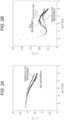
Figs. 2A and 2B are diagrams illustrating a tendency of changes in dielectric constant (relative dielectric constant and relative dielectric loss factor) according to a change in a frequency. Here, in the configuration illustrated inFig. 1 , the relative dielectric constant εr' and the relative dielectric loss factor εr" of the lubricant in the rolling bearing provided in thebearing device 2 are measured by conducting tests under the following conditions and the dielectric relaxation phenomenon caused by the lubricant in the rolling bearing is checked. Here, the measurement is performed in a state where the outer ring temperature is 23°C. In addition, the measurement results of the lubricant (bulk state) at a temperature of 23°C are shown for comparison with the oil film of the lubricant in the rolling bearing. Note that all the lubricants are the same, and it is assumed that the lubricant in the bulk state does not change in temperature during the measurement. -
- bearing: deep groove ball bearing (brand number: 6306)
- rotation speed: 997 [min-1]
- axial load: 1000 [N]
- radial load: 0 [N]
- temperature: 23 [°C]
- lubricant: lithium-based grease
- AC voltage: 1.0 [V]
- AC power frequency: 20 to 1M [Hz]
- In
Fig. 2A , the horizontal axis indicates a logarithm of a frequency [Hz], and the vertical axis indicates the relative dielectric constant εr'.Fig. 2A illustrates experimental values of the oil film due to the lubricant and the lubricant in a bulk state in the rolling bearing obtained as a result of the above test. As illustrated inFig. 2A , in any measurement results, the relative dielectric constant εr' tends to decrease (monotonically decrease) as the frequency increases. - In
Fig. 2B , the horizontal axis indicates the logarithm of the frequency [Hz], and the vertical axis indicates the relative dielectric loss factor εr".Fig. 2B illustrates experimental values of the oil film due to the lubricant and the lubricant in a bulk state in the rolling bearing obtained as a result of the above test. As illustrated inFig. 2B , in any measurement results, after the relative dielectric loss factor εr" once decreases as the frequency increases, the relative dielectric loss factor εr" tends to rise and, after that, decreases again. - Referring to
Figs. 2A and 2B , there is a difference in the measurement results of the oil film due to the lubricant (bulk state) and the lubricant in the rolling bearing. As illustrated inFig. 2B , the relaxation time τ (peak position) moves to the high frequency side in the measurement result of the oil film due to the lubricant in the rolling bearing. Further, the DC conductivity σ0 is higher in the measurement result of the oil film due to the lubricant in the rolling bearing. The reason for such a difference is that the temperature of the oil film in the rolling bearing rose above the outer ring temperature (here, 23°C) due to the rolling operation of the rolling bearing. - In this embodiment, the temperature of the oil film caused by the lubricant in the rolling bearing is derived based on the correlation between the relaxation time and the temperature of the oil film caused by the lubricant in the rolling bearing.
Fig. 3 is a diagram illustrating the relationship between relaxation time τ and absolute temperature T. InFig. 3 , the vertical axis represents the relaxation time τ [µs], and the horizontal axis represents the absolute temperature T [K]. Here, an example of the measurement results of the lithium-based grease used in the test is illustrated. As illustrated inFig. 3 , the absolute temperature T increases as the relaxation time τ decreases. Referring toFig. 3 , it can be read that there is a correlation between the relaxation time τ and the absolute temperature T. - First, the relaxation time τ can be defined as the following formula (4) based on Eyring equation.
[Formula 1]
- τ: relaxation time [s]
- K: equilibrium constant
- h: Planck's constant
- R: gas constant
- kB: Boltzmann constant
- T: absolute temperature
- ΔH‡: activation enthalpy
- ΔS‡: activation entropy
- ΔG‡: activation Gibbs energy (= ΔH‡ - TΔS‡)
- exp: exponential function
- When the above formula (4) is rearranged with respect to the absolute temperature T using the Lambert W function, it can be defined as the following formula (5).
[Formula 2]
W: Lambert W function - In the present embodiment, the above formula (5) is used in deriving the temperature of the oil film due to the lubricant in the rolling bearing under the axial load. The equilibrium constant K, Planck's constant h, gas constant R, and Boltzmann's constant kB are preset. As the values of the activation enthalpy ΔH‡ and the activation entropy ΔS‡, the values of the lubricant in the bulk state are measured in advance and used. More specifically, the values of the activation enthalpy ΔH‡ and the activation entropy ΔS‡ can be derived by applying the actual measured values using the following formula (6).
[Formula 3]
ln: logarithmic function - As an example of the lithium-based grease used in the above tests, 12-OH Li stearatebased grease is used as the lubricant. In this case, when the activation enthalpy ΔH‡ and the activation entropy ΔS‡ were obtained from the relationship between the relaxation time τ and the absolute temperature T for the lubricant at the bulk state using the above formula (6), the following values are obtained.


- Next, derivation of parameters related to the dielectric relaxation phenomenon due to the lubricant in the rolling bearing will be described. The electrical characteristics based on the dielectric relaxation phenomenon of the lubricant in the rolling bearing have a change tendency as illustrated in
Figs. 2A and 2B . In order to specify the electrical characteristics of this change tendency, the measured values are applied (fitting) to a theoretical formula to derive various parameters. In this embodiment, the relaxation time τ is specified in order to derive the temperature of the oil film of the lubricant in the rolling bearing. In this embodiment, the theoretical formulas represented in the following formulas (7) to (9) are used.
[Formula 4]
[Formula 5]
[Formula 6]
- εr0: relative dielectric constant at low frequency limit
- er∞: relative dielectric constant at high frequency limit
- τ: relaxation time [s]
- β: constant representing distribution of relaxation time
- σ0: DC conductivity [S/m]
- ε0: dielectric constant of vacuum
- π: circumference ratio
- f: frequency
-
Fig. 4 compares the curves obtained by fitting the above theoretical formulas with experimental values obtained using the configuration illustrated inFig. 1 . Here, the description will focus on the relative dielectric loss factor εr" for specifying the relaxation time τ, which is the object of the present embodiment. InFig. 4 , the horizontal axis represents the logarithm of the frequency [Hz], and the vertical axis represents the relative dielectric loss factor εr". As illustrated inFig. 4 , by fitting, the theoretical value can express the tendency of the experimental value for the relative dielectric loss factor. - By applying the above theoretical formula, it becomes possible to derive the relaxation time τ, which is a parameter of the electrical characteristics of the lubricant. In the example illustrated in
Fig. 4 , 1.2 [µS] was derived for the relaxation time τ. Then, by substituting this value into the above formula (5), the absolute temperature T [K] can be calculated. As a result, 46.3 [°C] is derived as the temperature of the oil film of the lubricant in the rolling bearing. - Note that the theoretical formulas shown in formulas (7) to (9) are based on Cole-Cole type theoretical formula and are only examples. For this reason, the present invention is not limited to this theoretical formula, and other theoretical formulas may be used.
-
Fig. 5 is a diagram illustrating the results of measuring the relative dielectric loss factor by frequency sweep in the temperature rise of the outer ring of the rolling bearing over time using the configuration illustrated inFig. 1 . InFig. 5 , the vertical axis represents the relative dielectric loss factor εr" and the horizontal axis represents the logarithm of the frequency [Hz]. In addition, four temperatures of 23°C, 25°C, 27°C, and 29°C are used for explanation here as the temperature of the outer ring. As illustrated inFig. 5 , as the temperature of the outer ring increases, the relaxation time τ (peak position) moves to the high frequency side. That is, it can be read that there is a correlation between the temperature and the relaxation time. -
Fig. 6 is a diagram illustrating the correspondence between the oil film temperature calculated using the relaxation time τ derived from the measurement result ofFig. 5 and the formula (5), and the outer ring temperature. Referring toFig. 6 , the oil film temperature of the lubricant in the rolling bearing increases as the relaxation time τ decreases. In addition, these are all calculated values that are hotter than the actual measured outer ring temperature. That is, as illustrated inFig. 6 , the temperature derivation method according to the present embodiment can derive the temperature of the lubricant itself instead of the outer ring. - In addition, in the test examples above, the inner ring is illustrated as a rotating ring under constant speed and constant load. Similarly, the method according to the present embodiment can be applied to a configuration in which the outer ring is a rotating ring.
-
Fig. 7 is a flowchart of a temperature detection process according to this embodiment. This processing is executed by thediagnosis device 1, and for example, a control device (not illustrated) included in thediagnosis device 1 reads a program for realizing the processing according to this embodiment from a storage device (not illustrated) and executes the program may realize this processing. - At S701, the
diagnosis device 1 controls thebearing device 2 so that the axial load is applied in a predetermined load direction. It is noted that the control of applying the axial load may be performed by a device other than thediagnosis device 1. At this time, the phase and the impedance in a static contact state are measured. - At S702, the
diagnosis device 1 allows themotor 10 to start rotating therotating shaft 7. Accordingly, the rotation of theinner ring 4 connected to therotating shaft 7 is started. It is noted that the control of themotor 10 may be performed by a device other than thediagnosis device 1. - In S703, the
diagnosis device 1 controls the LCR meter 8 to apply the AC voltage V having the angular frequency ω to thebearing device 2 by using an AC power supply (not illustrated) provided in the LCR meter 8. Accordingly, the AC voltage V having the angular frequency ω is applied to thebearing device 2. - At S704, the
diagnosis device 1 acquires the impedance |Z| and the phase angle θ from the LCR meter 8 as outputs for the input in S703. That is, the LCR meter 8 outputs the impedance |Z| and the phase angle θ to thediagnostic device 1, as a result of the detection of thebearing device 2 for the input AC voltage V and the angle frequency ω of the AC voltage. - In S705, the
diagnosis device 1 reads various parameters for deriving the temperature of the oil film from the storage unit. Specifically, the parameters used in the formula (5) are acquired for the lubricant used in the rolling bearing. These parameters are defined in advance and stored in a storage device (not illustrated) or the like. - In S706, the
diagnosis device 1 derives the relative dielectric constant and relative dielectric loss factor corresponding to each frequency based on the impedance |Z| and phase angle θ obtained in S704 and the information on the AC voltage V at the angular frequency ω indicated in S703. A known method may be used for the derivation method here. Further, the LCR meter 8 may be configured to derive the relative dielectric constant and relative dielectric loss factor, and output the relative dielectric constant and relative dielectric loss factor together with the impedance |Z| and phase angle θ to thediagnosis device 1 as measurement results. - In S707, the
diagnosis device 1 applies (fitting) the obtained measurement results to the theoretical formulas shown in the above formulas (7) to (9). - At S708, the
diagnosis device 1 derives the relaxation time τ from the fitting result of S707. A well-known technique may be used as a method for deriving the relaxation time τ here. - At S709, the
diagnosis device 1 derives the oil film temperature based on the relaxation time τ derived at S708 and various parameters acquired at S705. Specifically, thediagnosis device 1 calculates the absolute temperature T by substituting various parameters into the above formula (2) and converts it into an oil film temperature (Celsius temperature). Note that the oil film temperature may be output as an absolute temperature [K] value. - At S710, the
diagnosis device 1 performs a state diagnosis of the lubricant based on the oil film temperature derived at S709. Although the contents of the diagnosis here are not particularly limited, for example, a threshold value may be set for the oil film temperature, and normality or abnormality may be diagnosed by comparison with the threshold value. - In S711, the
diagnosis device 1 notifies the user of the diagnostic result obtained in S710. The notification method here is not particularly limited, but for example, the value of the oil film temperature and the transition of the temperature may be displayed on the screen. Moreover, the configuration may be such that an abnormal temperature rise or the like is notified according to the operating conditions. Then, the processing flow is ended. - As described above, according to the present embodiment, it is possible to derive the oil film temperature even when it is difficult to directly measure the oil film temperature of a lubricant in a device that uses a lubricant, such as a rolling bearing. Moreover, based on this, it becomes possible to easily diagnose the state of the device.
- In the above embodiment, the oil film due to the lubricant in the rolling bearing has been described as an example, but the present invention is not limited thereto. For example, the method according to the present invention can be applied to any substance that is used in a device and whose temperature is difficult to be directly detected and that causes dielectric relaxation, not limited to lubricants. Moreover, the applicable device is not limited to rolling bearings, and the method according to the present invention can be applied to other rolling devices using substances that cause dielectric relaxation.
- Also, in the above example, lithium-based grease was used as an example of the lubricant, but the lubricant is not limited thereto. As described above, the method according to the present invention can also be applied to lubricants that cause dielectric relaxation.
- In addition, the present invention can also be realized by processes in which programs or applications for implementing the functions of one or more embodiments described above is supplied to a system or device by using a network, a storage medium, or the like, and one or more processors in a computer of the system or device reads and executes the programs.
- In addition, the present invention may also be realized by a circuit (for example, an ASIC (application specific integrated circuit) or an FPGA (field programmable gate array)) implementing one or more functions.
- As described above, the present invention is not limited to the above-described embodiments, and those skilled in the art can make modifications and applications by combining the respective configurations of the embodiments with each other based on the description of the specification and well-known techniques, which are also contemplated by the present invention and falls within the scope of protection of the present invention.
- As described above, this specification discloses the following matters.
- (1) A temperature derivation method for deriving the oil film temperature of the lubricant in a device, the temperature derivation method including:
- a measurement step of measuring the dielectric constant of the lubricant by applying an alternating voltage while changing the frequency to an electric circuit configured by the device;
- a derivation step of applying the dielectric constant measured in the measurement step to a theoretical formula to derive a relaxation time of the lubricant; and
- a calculation step of calculating the oil film temperature by using the relaxation time.
According to this configuration, even if it is difficult to directly measure the oil film temperature of the lubricant in a device using a lubricant, the oil film temperature can be derived. - (2) The temperature derivation method according to (1), in which
- in the calculation step,
- the oil film temperature is calculated using

- in which the activation enthalpy ΔH‡ and the activation entropy ΔS‡ are values of the lubricant in a bulk state.
According to this configuration, it is possible to easily derive the oil film temperature of the lubricant by using the information on the lubricant in the bulk state.
- (3) The temperature derivation method according to (1) or 2, in which
the theoretical formulas are represented by


According to this configuration, the electrical characteristics of the dielectric relaxation phenomenon caused by the lubricant in the device can be specified with high accuracy, and the oil film temperature of the lubricant can be derived based on the value based on the electrical characteristics. - (4) The temperature derivation method according to any one of (1) to (3), further including a diagnosis step of diagnosing the state of the device using the oil film temperature calculated in the calculation step.
According to this configuration, it is also possible to easily diagnose the state of the device based on the calculated oil film temperature. - (5) The temperature derivation method according to any one of (1) to (4), in which the device is a rolling device.
According to this configuration, even when it is difficult to directly measure the oil film temperature of the lubricant in the rolling device, the oil film temperature can be derived. - (6) The temperature derivation method according to any one of (1) to (4), in which the device is a rolling bearing.
According to this configuration, even when it is difficult to directly measure the oil film temperature of the lubricant in the rolling bearing, the oil film temperature can be derived. - (7) A temperature derivation device for detecting an oil film temperature of a lubricant in a device, the temperature derivation device including:
- a measurement unit measuring a dielectric constant of the lubricant by applying an alternating voltage while changing a frequency to an electric circuit configured by the device;
- a derivation unit applying the dielectric constant measured in the measurement unit to a theoretical formula to derive a relaxation time of the lubricant; and
- a calculation unit calculating the oil film temperature by using the relaxation time.
According to this configuration, even if it is difficult to directly measure the oil film temperature of the lubricant in a device using a lubricant, the oil film temperature can be derived. - (8) A program causing a computer to execute:
- a measurement step of measuring a dielectric constant of a lubricant in a device by applying an alternating voltage while changing a frequency to an electric circuit configured by the device;
- a derivation step of applying the dielectric constant measured in the measurement step to a theoretical formula to derive a relaxation time of the lubricant; and
- a calculation step of calculating an oil film temperature of the lubricant by using the relaxation time.
- According to this configuration, even if it is difficult to directly measure the oil film temperature of the lubricant in a device using a lubricant, the oil film temperature can be derived.
- Heretofore, although various embodiments have been described above with reference to the drawings, it goes without saying that the present invention is not limited to such examples. It is obvious that persons skilled in the art can conceive of various changes or modifications within the scope disclosed in the claims, and it is understood that these also belong to the technical scope of the present invention. In addition, components in the above-described embodiments may be combined arbitrarily without departing from the spirit of the invention.
- It is noted that this application is based on Japanese patent application (
Japanese patent application 2020-163962) filed on September 29, 2020 Japanese patent application 2021-137563) filed on August 25, 2021 -
- 1: diagnosis device
- 2: bearing device
- 3: outer ring (outer member)
- 4: inner ring (inner member)
- 5: rolling element
- 6: seal
- 7: rotating shaft
- 8: LCR meter
- 9: rotation connector
- 10: motor
Claims (8)
- A temperature derivation method for deriving an oil film temperature of a lubricant in a device, the temperature derivation method comprising:a measurement step of measuring a dielectric constant of the lubricant by applying an alternating voltage while changing a frequency to an electric circuit configured by the device;a derivation step of applying the dielectric constant measured in the measurement step to a theoretical formula to derive a relaxation time of the lubricant; anda calculation step of calculating the oil film temperature by using the relaxation time.
- The temperature derivation method according to claim 1, whereinin the calculation step,the oil film temperature is calculated using
 wherein an activation enthalpy ΔH‡ and an activation entropy ΔS‡ are values of the lubricant in a bulk state.
 - The temperature derivation method according to claim 1 or 2, wherein
the theoretical formulas are represented by


- The temperature derivation method according to any one of claims 1 to 3, further comprising a diagnosis step of diagnosing a state of the device using the oil film temperature calculated in the calculation step.
- The temperature derivation method according to any one of claims 1 to 4, wherein the device is a rolling device.
- The temperature derivation method according to any one of claims 1 to 4, wherein the device is a rolling bearing.
- A temperature derivation device for detecting an oil film temperature of a lubricant in a device, the temperature derivation device comprising:a measurement unit measuring a dielectric constant of the lubricant by applying an alternating voltage while changing a frequency to an electric circuit configured by the device;a derivation unit applying the dielectric constant measured in the measurement unit to a theoretical formula to derive a relaxation time of the lubricant; anda calculation unit calculating the oil film temperature by using the relaxation time.
- A program causing a computer to execute:a measurement step of measuring a dielectric constant of a lubricant in a device by applying an alternating voltage while changing a frequency to an electric circuit configured by the device;a derivation step of applying the dielectric constant measured in the measurement step to a theoretical formula to derive a relaxation time of the lubricant; anda calculation step of calculating an oil film temperature of the lubricant by using the relaxation time.
Applications Claiming Priority (3)
| Application Number | Priority Date | Filing Date | Title |
|---|---|---|---|
| JP2020163962 | 2020-09-29 | ||
| JP2021137563 | 2021-08-25 | ||
| PCT/JP2021/035205 WO2022071163A1 (en) | 2020-09-29 | 2021-09-24 | Temperature derivation method for oil film, temperature derivation device, and program |
Publications (3)
| Publication Number | Publication Date |
|---|---|
| EP4224136A1 true EP4224136A1 (en) | 2023-08-09 |
| EP4224136A4 EP4224136A4 (en) | 2024-03-27 |
| EP4224136B1 EP4224136B1 (en) | 2026-05-06 |
Family
ID=80951627
Family Applications (1)
| Application Number | Title | Priority Date | Filing Date |
|---|---|---|---|
| EP21875465.3A Active EP4224136B1 (en) | 2020-09-29 | 2021-09-24 | Temperature derivation method for oil film, temperature derivation device, and program |
Country Status (7)
| Country | Link |
|---|---|
| US (1) | US20230366750A1 (en) |
| EP (1) | EP4224136B1 (en) |
| JP (2) | JP7115658B1 (en) |
| KR (1) | KR20230078742A (en) |
| BR (1) | BR112023005688A2 (en) |
| TW (1) | TWI882180B (en) |
| WO (1) | WO2022071163A1 (en) |
Families Citing this family (1)
| Publication number | Priority date | Publication date | Assignee | Title |
|---|---|---|---|---|
| KR20230074778A (en) * | 2020-09-29 | 2023-05-31 | 닛본 세이고 가부시끼가이샤 | Oil slick state detection method, state detection device, and program |
Family Cites Families (11)
| Publication number | Priority date | Publication date | Assignee | Title |
|---|---|---|---|---|
| US5788376A (en) * | 1996-07-01 | 1998-08-04 | General Motors Corporation | Temperature sensor |
| US6449580B1 (en) * | 1998-05-11 | 2002-09-10 | Entek Ird International Corporation | Evaluating properties of oil using dielectric spectroscopy |
| TWI388810B (en) * | 2008-12-26 | 2013-03-11 | Univ Ishou | Measurement Method of Temperature Value of Lubricating Medium Between Two Objects Rolling |
| EP2401517B1 (en) * | 2009-01-28 | 2018-03-14 | Ab Skf | Lubrication condition monitoring |
| JP2012052941A (en) * | 2010-09-02 | 2012-03-15 | Nihon Univ | Distribution specifying method and distribution specifying device |
| US10890575B2 (en) * | 2016-04-28 | 2021-01-12 | Nsk Ltd. | Lubricant deterioration detection device and lubricant deterioration state evaluation method |
| DE102018203258B4 (en) * | 2018-03-05 | 2020-02-06 | Bombardier Transportation Gmbh | Drive, rail vehicle and method for improving the use of lubricant in a drive of a vehicle |
| JP6729633B2 (en) | 2018-06-04 | 2020-07-22 | 日本精工株式会社 | Diagnosis method of rolling device |
| KR102611596B1 (en) * | 2019-01-15 | 2023-12-07 | 닛본 세이고 가부시끼가이샤 | Diagnosis methods for powertrains |
| JP7234004B2 (en) | 2019-03-29 | 2023-03-07 | 本田技研工業株式会社 | gear device |
| US11159124B2 (en) | 2020-03-09 | 2021-10-26 | Biosense Webster (Israel) Ltd. | Sine-wave generation using pulsed D-class amplifier |
-
2021
- 2021-09-24 BR BR112023005688A patent/BR112023005688A2/en unknown
- 2021-09-24 EP EP21875465.3A patent/EP4224136B1/en active Active
- 2021-09-24 US US18/247,046 patent/US20230366750A1/en active Pending
- 2021-09-24 KR KR1020237014210A patent/KR20230078742A/en active Pending
- 2021-09-24 JP JP2022502567A patent/JP7115658B1/en active Active
- 2021-09-24 WO PCT/JP2021/035205 patent/WO2022071163A1/en not_active Ceased
- 2021-09-29 TW TW110136279A patent/TWI882180B/en active
-
2022
- 2022-07-13 JP JP2022112530A patent/JP7768060B2/en active Active
Also Published As
| Publication number | Publication date |
|---|---|
| TWI882180B (en) | 2025-05-01 |
| JPWO2022071163A1 (en) | 2022-04-07 |
| TW202235832A (en) | 2022-09-16 |
| KR20230078742A (en) | 2023-06-02 |
| JP2022160448A (en) | 2022-10-19 |
| WO2022071163A1 (en) | 2022-04-07 |
| JP7768060B2 (en) | 2025-11-12 |
| US20230366750A1 (en) | 2023-11-16 |
| EP4224136B1 (en) | 2026-05-06 |
| BR112023005688A2 (en) | 2023-04-25 |
| JP7115658B1 (en) | 2022-08-09 |
| EP4224136A4 (en) | 2024-03-27 |
Similar Documents
| Publication | Publication Date | Title |
|---|---|---|
| EP4224026B1 (en) | OIL FILM CONDITION DETECTION METHOD, CONDITION DETECTION DEVICE AND PROGRAM | |
| JP7248198B2 (en) | Bearing device state detection method, detection device, and program | |
| EP4224136B1 (en) | Temperature derivation method for oil film, temperature derivation device, and program | |
| TW202400978A (en) | Status detection method, detection device and program of bearing device | |
| EP4495570A1 (en) | State diagnosis method, state diagnosis device, and program | |
| CN116547516A (en) | Method, device and program for deriving temperature of oil film | |
| JP7168139B1 (en) | Bearing device state detection method, detection device, and program | |
| CN120225849A (en) | State measurement method, state measurement device, and program | |
| EP4495569A1 (en) | Bearing device state detecting method, detecting device, and program | |
| EP4560160A1 (en) | Water intrusion detection method, water intrusion detection device, and program for device using lubricant | |
| JP2024140594A (en) | Method, device, and program for measuring temperature and pressure of lubricant | |
| EP4495568A1 (en) | Measurement method, observation device, and program | |
| WO2025142842A1 (en) | Lubrication state diagnosis device, diagnosis method, and program | |
| BR112023004613B1 (en) | METHOD FOR DETECTING THE STATE OF THE ROLLING DEVICE, DETECTION DEVICE AND COMPUTER-READABLE MEDIUM | |
| TW202346729A (en) | Bearing device state detection method, detection device, and program |
Legal Events
| Date | Code | Title | Description |
|---|---|---|---|
| STAA | Information on the status of an ep patent application or granted ep patent |
Free format text: STATUS: THE INTERNATIONAL PUBLICATION HAS BEEN MADE |
|
| PUAI | Public reference made under article 153(3) epc to a published international application that has entered the european phase |
Free format text: ORIGINAL CODE: 0009012 |
|
| STAA | Information on the status of an ep patent application or granted ep patent |
Free format text: STATUS: REQUEST FOR EXAMINATION WAS MADE |
|
| 17P | Request for examination filed |
Effective date: 20230327 |
|
| AK | Designated contracting states |
Kind code of ref document: A1 Designated state(s): AL AT BE BG CH CY CZ DE DK EE ES FI FR GB GR HR HU IE IS IT LI LT LU LV MC MK MT NL NO PL PT RO RS SE SI SK SM TR |
|
| DAV | Request for validation of the european patent (deleted) | ||
| DAX | Request for extension of the european patent (deleted) | ||
| A4 | Supplementary search report drawn up and despatched |
Effective date: 20240223 |
|
| RIC1 | Information provided on ipc code assigned before grant |
Ipc: F16C 33/66 20060101ALI20240219BHEP Ipc: F16C 19/52 20060101ALI20240219BHEP Ipc: F16C 19/22 20060101ALI20240219BHEP Ipc: F16C 19/02 20060101ALI20240219BHEP Ipc: G01K 7/34 20060101ALI20240219BHEP Ipc: G01K 1/14 20210101ALI20240219BHEP Ipc: G01M 13/04 20190101AFI20240219BHEP |
|
| GRAJ | Information related to disapproval of communication of intention to grant by the applicant or resumption of examination proceedings by the epo deleted |
Free format text: ORIGINAL CODE: EPIDOSDIGR1 |
|
| GRAP | Despatch of communication of intention to grant a patent |
Free format text: ORIGINAL CODE: EPIDOSNIGR1 |
|
| GRAP | Despatch of communication of intention to grant a patent |
Free format text: ORIGINAL CODE: EPIDOSNIGR1 |
|
| STAA | Information on the status of an ep patent application or granted ep patent |
Free format text: STATUS: GRANT OF PATENT IS INTENDED |
|
| INTG | Intention to grant announced |
Effective date: 20251219 |
|
| GRAS | Grant fee paid |
Free format text: ORIGINAL CODE: EPIDOSNIGR3 |
|
| GRAA | (expected) grant |
Free format text: ORIGINAL CODE: 0009210 |
|
| STAA | Information on the status of an ep patent application or granted ep patent |
Free format text: STATUS: THE PATENT HAS BEEN GRANTED |
|
| AK | Designated contracting states |
Kind code of ref document: B1 Designated state(s): AL AT BE BG CH CY CZ DE DK EE ES FI FR GB GR HR HU IE IS IT LI LT LU LV MC MK MT NL NO PL PT RO RS SE SI SK SM TR |
|
| REG | Reference to a national code |
Ref country code: CH Ref legal event code: F10 Free format text: ST27 STATUS EVENT CODE: U-0-0-F10-F00 (AS PROVIDED BY THE NATIONAL OFFICE) Effective date: 20260506 Ref country code: GB Ref legal event code: FG4D |