EP4224069A1 - Glass breakage mitigation using silicone rubber or similar material - Google Patents
Glass breakage mitigation using silicone rubber or similar material Download PDFInfo
- Publication number
- EP4224069A1 EP4224069A1 EP23154983.3A EP23154983A EP4224069A1 EP 4224069 A1 EP4224069 A1 EP 4224069A1 EP 23154983 A EP23154983 A EP 23154983A EP 4224069 A1 EP4224069 A1 EP 4224069A1
- Authority
- EP
- European Patent Office
- Prior art keywords
- glass substrate
- single planar
- gasket
- planar glass
- cooktop
- Prior art date
- Legal status (The legal status is an assumption and is not a legal conclusion. Google has not performed a legal analysis and makes no representation as to the accuracy of the status listed.)
- Withdrawn
Links
Images



Classifications
-
- F—MECHANICAL ENGINEERING; LIGHTING; HEATING; WEAPONS; BLASTING
- F24—HEATING; RANGES; VENTILATING
- F24C—DOMESTIC STOVES OR RANGES ; DETAILS OF DOMESTIC STOVES OR RANGES, OF GENERAL APPLICATION
- F24C15/00—Details
- F24C15/10—Tops, e.g. hot plates; Rings
- F24C15/108—Mounting of hot plate on worktop
-
- F—MECHANICAL ENGINEERING; LIGHTING; HEATING; WEAPONS; BLASTING
- F24—HEATING; RANGES; VENTILATING
- F24C—DOMESTIC STOVES OR RANGES ; DETAILS OF DOMESTIC STOVES OR RANGES, OF GENERAL APPLICATION
- F24C15/00—Details
- F24C15/10—Tops, e.g. hot plates; Rings
-
- F—MECHANICAL ENGINEERING; LIGHTING; HEATING; WEAPONS; BLASTING
- F24—HEATING; RANGES; VENTILATING
- F24C—DOMESTIC STOVES OR RANGES ; DETAILS OF DOMESTIC STOVES OR RANGES, OF GENERAL APPLICATION
- F24C7/00—Stoves or ranges heated by electric energy
- F24C7/08—Arrangement or mounting of control or safety devices
- F24C7/082—Arrangement or mounting of control or safety devices on ranges, e.g. control panels, illumination
- F24C7/083—Arrangement or mounting of control or safety devices on ranges, e.g. control panels, illumination on tops, hot plates
-
- C—CHEMISTRY; METALLURGY
- C08—ORGANIC MACROMOLECULAR COMPOUNDS; THEIR PREPARATION OR CHEMICAL WORKING-UP; COMPOSITIONS BASED THEREON
- C08L—COMPOSITIONS OF MACROMOLECULAR COMPOUNDS
- C08L83/00—Compositions of macromolecular compounds obtained by reactions forming in the main chain of the macromolecule a linkage containing silicon with or without sulfur, nitrogen, oxygen or carbon only; Compositions of derivatives of such polymers
- C08L83/04—Polysiloxanes
Definitions
- the present disclosure generally relates to a glass cooktop for kitchen ranges or kitchen countertop applications, and more specifically, to a glass cooktop having a single planar glass substrate and a gasket is disposed on the interior surface radially inward from the perimeter of the single planar glass substrate.
- a glass cooktop includes a single planar glass substrate having an exposed upper surface and an interior lower surface. A perimeter is disposed about an outer edge of the single planar glass substrate. A gasket is disposed on the interior surface radially inward from the perimeter of the single planar glass substrate. The gasket is adapted to absorb energy associated with breaking of the single planar glass substrate such that a plurality of broken sections of the single planar glass substrate are retained by the gasket.
- the gasket may comprise a bead of silicone.
- the bead of silicone may extend about an entirety of the perimeter.
- the single planar glass substrate further may include a bead extending between a pair of opposed sides of single planar glass substrate.
- the bead of silicone may be applied robotically.
- the single planar glass substrate may have a substantially rectilinear configuration having four corners, wherein a one of a plurality of connectors is disposed at each of the four corners of the interior surface of the single planar glass substrate.
- the gasket may be disposed on the interior surface radially inward from the perimeter of the single planar glass substrate and may include four individual linear sections that each extend between an adjacent two connectors of the plurality of connectors.
- Each of the plurality of connectors may comprise a single-sided adhesive or a double-sided adhesive.
- the gasket may comprises a tape adhered to the interior surface of the single planar glass substrate.
- a glass cooktop includes a single planar glass substrate, wherein the single planar glass substrate further includes an exterior surface and an interior surface defining a polygonal configuration having a plurality of corners.
- a plurality of connectors is disposed on each of the plurality of corners of the interior surface of the single planar glass substrate.
- a gasket is disposed on the interior surface radially inward from a perimeter of the single planar glass substrate, wherein the gasket includes a plurality of individual linear sections that each extend between an adjacent pair of the plurality of connectors.
- the plurality of connectors may comprise a single-sided adhesive or a double-sided adhesive and the gasket may comprise a tape adhered to the interior surface of the single planar glass substrate by a single-sided adhesive or a double-sided adhesive.
- Each of the plurality of connectors may comprise a plurality of overlapping and angularly displaced tape strips.
- the plurality of overlapping and angularly displaced tape strips may be set substantially orthogonally to each other.
- the plurality of overlapping and angularly displaced tape strips may include a tape strip set obliquely to each of the tape strips set substantially orthogonally to each other.
- Each of the plurality of connectors have a planar shape conforming to a geometry of a one each of the plurality of corners.
- the gasket may comprise a reinforcing structure; and the reinforcing structure may comprise a plurality of parallel ribs disposed along a longitudinal length of and on a planar surface of the gasket.
- a method of absorbing energy associated with breaking a single planar glass substrate of a cooktop whereby a plurality of broken sections of the single planar glass substrate are retained.
- the method includes the steps of: providing the single planar glass substrate having an exposed upper exterior surface and a lower interior surface; disposing a gasket on the interior surface radially inward from a perimeter disposed about an outer edge of the single planar glass substrate; and installing the single planar glass substrate on the cooktop, such that the gasket is adapted to absorb energy and retain the plurality of broken sections in the single planar glass substrate in the event of glass breakage.
- Further features of this aspect of the present disclosure include the step of disposing the gasket on the interior surface radially inward from a perimeter disposed about an outer edge of the single planar glass substrate may be obtained by applying the gasket as a bead of silicone about an entirety of the perimeter robotically.
- the method may further comprise the step of disposing a plurality of connectors on each of a plurality of corners of the interior surface of the single planar glass substrate, such that the gasket is disposed on the interior surface radially inward from a perimeter of the glass substrate, and wherein the gasket includes a plurality of individual linear sections that each extend between an adjacent pair of the plurality of connectors.
- the present illustrated embodiments reside primarily in combinations of method steps and apparatus components related to a single planar glass substrate of the glass cooktop. Accordingly, the apparatus components and method steps have been represented, where appropriate, by conventional symbols in the drawings, showing only those specific details that are pertinent to understanding the embodiments of the present disclosure so as not to obscure the disclosure with details that will be readily apparent to those of ordinary skill in the art having the benefit of the description herein. Further, like numerals in the description and drawings represent like elements.
- the terms “upper,” “lower,” “right,” “left,” “rear,” “front,” “vertical,” “horizontal,” and derivatives thereof shall relate to the disclosure as oriented in FIG. 1 .
- the term “front” shall refer to the surface of the element closer to an intended viewer, and the term “rear” shall refer to the surface of the element further from the intended viewer.
- the disclosure may assume various alternative orientations, except where expressly specified to the contrary.
- the specific devices and processes illustrated in the attached drawings, and described in the following specification are simply exemplary embodiments of the inventive concepts defined in the appended claims. Hence, specific dimensions and other physical characteristics relating to the embodiments disclosed herein are not to be considered as limiting, unless the claims expressly state otherwise.
- reference numeral 10 generally designates a glass cooktop 10 that includes a single planar glass substrate 12.
- the glass cooktop 10 may be used in a freestanding device, such as a kitchen range with cooktop and an oven, or as a stand-alone unit mounted directly to a kitchen countertop 14, as shown in FIG. 1 .
- a stand-alone unit shown in FIG. 3
- a base 16 of the glass cooktop 10 may be mounted in an opening 18 in the countertop 14, with a base gasket 20 provided to prevent debris from infiltrating the installation.
- the single planar glass substrate 12 is disposed within a recess 22 on an upper surface 24 of the base 16 of the glass cooktop 10, as further described below.
- heating elements or induction elements may be disposed below the glass cooktop 10 or, as shown, element openings 26 may be provided for the placement of such heating elements or induction elements.
- control openings 28 may be provided to allow the installation of rotary controls (not shown) for turning the heating elements or induction elements on or off and for controlling the intensity of the energy output of the heating elements or induction elements, as is known.
- rotary controls not shown
- Different arrangements of the element openings 26 and the control openings 28 may be contemplated, as depicted in the Figures.
- the single planar glass substrate 12 includes an upper exterior surface 30 and a lower interior surface 32.
- a perimeter 34 disposed about an outer edge 36 of the single planar glass substrate 12 defines the configuration of the cooktop. That is, the glass cooktop 10 and the single planar glass substrate 12 may have a polygonal configuration having a plurality of corners 38. As shown in the Figures, the single planar glass substrate 12 has a substantially rectilinear configuration having four corners 38. However, other configurations may be adopted.
- a gasket 40 may be disposed on the interior surface 32 of the single planar glass substrate 12, where gasket 40 is disposed radially inward from the perimeter 34 of the single planar glass substrate 12, as perhaps best seen in FIG. 3 .
- the radial inward distance (d) of the gasket 40 may be about 4 mm (+/- 2 mm) from the outer edge 36 of the single planar glass substrate 12. Smaller distances are desired. So positioned, the gasket 40 may be adapted to absorb energy associated with a breaking of the single planar glass substrate 12, such that a plurality of broken sections of the single planar glass substrate 12 are retained by the gasket 40.
- the gasket 40 should not be disposed at the outer edge 36 of the single planar glass substrate 12.
- the gasket 40 may be fabricated as a bead of silicone 42 extending about an entirety of the perimeter 34 of the single planar glass substrate 12.
- the gasket 40 may also comprise a hot melt adhesive so disposed.
- the gasket 40, formed as a bead of silicone 42, may have an installed width (w) of about 15 mm and an installed height (h) of about 2 mm, as again shown in FIG. 3 .
- the advantages of the present invention may be also obtained where the bead of silicone 42 extends about less than the entirety of the perimeter 34, for example, the bead of silicone 42 may be omitted from one side of the single planar glass substrate 12, such as a rear side 44, which may be less likely to generate broken sections of glass during a breakage event.
- the single planar glass substrate 12 may further include an additional silicone bead 46 extending between a pair of opposed sides 48, 50 of the single planar glass substrate 12, as shown in FIGS. 5 and 6 . That is, for reinforcement, additional beads of silicone 46 may be added as internal links.
- An advantageous feature of the present disclosure is the ability to have the gasket 40 applied robotically as the silicone bead 42. Such application technique promotes repeatability, reduces the complexity of manufacturing the cooktop, simplifies the overall process, and reduces the application time.
- a one of a plurality of connectors 52 may be disposed at each of the four corners 38 of the interior surface 32 of the single planar glass substrate 12.
- the gasket 40 again is disposed on the interior surface 32 radially inward from the perimeter 34 of the single planar glass substrate 12.
- the gasket 40 may also include a plurality of individual linear sections 54, as shown in FIGS. 7-10 as four individual linear sections 54, that each extends between an adjacent pair of connectors 52 of the plurality of connectors 52.
- the individual linear sections 54 of the gasket 40 may extend about an entirety of the perimeter 34 of the single planar glass substrate 12. However, the advantages of the present invention may be also obtained where the individual linear sections 54 of the gasket 40 extend less than the about an entirety of the perimeter 34, for example, where an individual linear section 54 of the gasket 40 may be omitted from one side of the single planar glass substrate 12, such as the rear side 44, which may be less likely to generate broken sections, as shown in FIGS. 8-10 .
- Each of the plurality of connectors 52 may comprise a single-sided adhesive or a double-sided adhesive.
- Each of the plurality of individual linear sections 54 of the gasket may comprise a tape adhered to the interior surface 32 of the single planar glass substrate 12, wherein the individual linear section 54 adhered to the interior surface 32 of the single planar glass substrate 12 may also include a single-sided adhesive or a double-sided adhesive.
- each of the plurality of connectors 52 may comprise a plurality of overlapping and angularly displaced tape strips 56, 58.
- the plurality of overlapping and angularly displaced tape strips 56, 58 may be set substantially orthogonally to each other.
- the plurality of overlapping and angularly displaced tape strips 56, 58 may also include a tape strip 60 set obliquely to each of the tape strips 56, 58 set substantially orthogonally to each other.
- each of the plurality of connectors 52 may have a planar shape conforming to the geometry of each of the plurality of corners 38, as shown in FIG. 11 .
- each of the plurality of connectors 52 may have a custom and unique configuration that is formed to match the outer edge 36 of the corner 38 of the perimeter 34 of the single planar glass substrate 12, depending on its specific geometry, that is disposing radially inward from the perimeter 34, as discussed above.
- the gasket 40 may also include a reinforcing structure 62 in order to avoid high deformation during a breakage event.
- the reinforcing structure 62 may include a plurality of parallel ribs 64 disposed along a longitudinal length of and on a planar surface 66 of the gasket 40.
- the method of absorbing energy associated with breaking of a single planar glass substrate 12 of a glass cooktop 10, whereby a plurality of broken sections of the single planar glass substrate 12 are retained includes the step of providing the single planar glass substrate 12 having the exposed upper exterior surface 30 and the lower interior surface 32. The method also includes the step of disposing the gasket 40 on the interior surface 32 radially inward the distance (d) from the perimeter 34 disposed about the outer edge 36 of the single planar glass substrate 12. The single planar glass substrate 12 is then installed on the glass cooktop 10, such that the gasket 40 is adapted to absorb energy and retain the plurality of broken sections in the single planar glass substrate 12 in the event of glass breakage.
- the step of disposing the gasket 40 on the interior surface 32 radially inward from a perimeter 34 disposed about an outer edge 36 of the single planar glass substrate 12 may be obtained by applying the gasket 40 as the bead of silicone 42 about an entirety of the perimeter 34 robotically.
- the method may further comprise the step of disposing the plurality of connectors 52 on each of the plurality of corners 38 of the interior surface 32 of the single planar glass substrate 12, such that the gasket 40 is disposed on the interior surface 32 radially inward from the perimeter 34 of the single planar glass substrate 12, and wherein the gasket 40 includes the plurality of individual linear sections 54 that each extends between an adjacent pair of the plurality of connectors 52.
- an objective is to contain glass shards or chips generated by a breakage of the glass cooktop 10 that might otherwise be directed toward a user of the glass cooktop 10 by retaining such glass shards or chips by the gasket 40.
- the gasket 40 formed as a silicone/hot melt adhesive bead 42 on the single planar glass substrate 12 absorbs the breakage energy, mitigating the hazard of fragments flying away from the glass cooktop 10.
- the gasket 40 is in the form of a plurality of individual linear sections 54 of single-sided tape or double-sided tape that each extends between adjacent two connectors 52 of the plurality of connectors 52, that may also be fabricated by single-sided tape or double-sided tape.
Landscapes
- Engineering & Computer Science (AREA)
- Chemical & Material Sciences (AREA)
- Combustion & Propulsion (AREA)
- Mechanical Engineering (AREA)
- General Engineering & Computer Science (AREA)
- Securing Of Glass Panes Or The Like (AREA)
Abstract
A glass cooktop (10) includes a single planar glass substrate (12) having an exposed upper surface (24) and an interior lower surface (32). A perimeter (34) is disposed about an outer edge (36) of the single planar glass substrate (12). A gasket (40) is disposed on the interior surface (32) radially inward from the perimeter (34) of the single planar glass substrate (12). The gasket (40) is adapted to absorb energy associated with a breaking of the single planar glass substrate (12) such that a plurality of broken sections of the single planar glass substrate (12) are retained by the gasket (40).
Description
- The present disclosure generally relates to a glass cooktop for kitchen ranges or kitchen countertop applications, and more specifically, to a glass cooktop having a single planar glass substrate and a gasket is disposed on the interior surface radially inward from the perimeter of the single planar glass substrate.
- According to one aspect of the present disclosure, a glass cooktop includes a single planar glass substrate having an exposed upper surface and an interior lower surface. A perimeter is disposed about an outer edge of the single planar glass substrate. A gasket is disposed on the interior surface radially inward from the perimeter of the single planar glass substrate. The gasket is adapted to absorb energy associated with breaking of the single planar glass substrate such that a plurality of broken sections of the single planar glass substrate are retained by the gasket.
- Further features of this aspect of the present disclosure include the gasket may comprise a bead of silicone. The bead of silicone may extend about an entirety of the perimeter. The single planar glass substrate further may include a bead extending between a pair of opposed sides of single planar glass substrate. The bead of silicone may be applied robotically. The single planar glass substrate may have a substantially rectilinear configuration having four corners, wherein a one of a plurality of connectors is disposed at each of the four corners of the interior surface of the single planar glass substrate. The gasket may be disposed on the interior surface radially inward from the perimeter of the single planar glass substrate and may include four individual linear sections that each extend between an adjacent two connectors of the plurality of connectors. Each of the plurality of connectors may comprise a single-sided adhesive or a double-sided adhesive. The gasket may comprises a tape adhered to the interior surface of the single planar glass substrate.
- According to another aspect of the present disclosure, a glass cooktop includes a single planar glass substrate, wherein the single planar glass substrate further includes an exterior surface and an interior surface defining a polygonal configuration having a plurality of corners. A plurality of connectors is disposed on each of the plurality of corners of the interior surface of the single planar glass substrate. A gasket is disposed on the interior surface radially inward from a perimeter of the single planar glass substrate, wherein the gasket includes a plurality of individual linear sections that each extend between an adjacent pair of the plurality of connectors.
- Further features of this aspect of the present disclosure include: the plurality of connectors may comprise a single-sided adhesive or a double-sided adhesive and the gasket may comprise a tape adhered to the interior surface of the single planar glass substrate by a single-sided adhesive or a double-sided adhesive. Each of the plurality of connectors may comprise a plurality of overlapping and angularly displaced tape strips. The plurality of overlapping and angularly displaced tape strips may be set substantially orthogonally to each other. The plurality of overlapping and angularly displaced tape strips may include a tape strip set obliquely to each of the tape strips set substantially orthogonally to each other. Each of the plurality of connectors have a planar shape conforming to a geometry of a one each of the plurality of corners. The gasket may comprise a reinforcing structure; and the reinforcing structure may comprise a plurality of parallel ribs disposed along a longitudinal length of and on a planar surface of the gasket.
- According to yet another aspect of the present disclosure, a method of absorbing energy associated with breaking a single planar glass substrate of a cooktop is provided, whereby a plurality of broken sections of the single planar glass substrate are retained. The method includes the steps of: providing the single planar glass substrate having an exposed upper exterior surface and a lower interior surface; disposing a gasket on the interior surface radially inward from a perimeter disposed about an outer edge of the single planar glass substrate; and installing the single planar glass substrate on the cooktop, such that the gasket is adapted to absorb energy and retain the plurality of broken sections in the single planar glass substrate in the event of glass breakage.
- Further features of this aspect of the present disclosure include the step of disposing the gasket on the interior surface radially inward from a perimeter disposed about an outer edge of the single planar glass substrate may be obtained by applying the gasket as a bead of silicone about an entirety of the perimeter robotically. The method may further comprise the step of disposing a plurality of connectors on each of a plurality of corners of the interior surface of the single planar glass substrate, such that the gasket is disposed on the interior surface radially inward from a perimeter of the glass substrate, and wherein the gasket includes a plurality of individual linear sections that each extend between an adjacent pair of the plurality of connectors.
- These and other features, advantages, and objects of the present disclosure will be further understood and appreciated by those skilled in the art by reference to the following specification, claims, and appended drawings.
- In the drawings:
-
FIG. 1 is a top perspective view of the single planar glass substrate of the glass cooktop according to the present disclosure; -
FIG. 2 is another top perspective view of the single planar glass substrate of the glass cooktop according to the present disclosure; -
FIG. 3 is a cross-sectional view of a portion of the glass cooktop base and single planar glass substrate of the glass cooktop according to the present disclosure shown inFIG. 1 ; -
FIG. 4 is a bottom plan view of a first embodiment of the single planar glass substrate of the glass cooktop according to the present disclosure shown inFIG. 1 ; -
FIG. 5 is another bottom plan view of the first embodiment of the single planar glass substrate provided with a silicone bead extending between a pair of opposed sides of single planar glass substrate according to the present disclosure, -
FIG. 6 is a cross-sectional bottom plan view of the silicone bead extending between a pair of opposed sides of single planar glass substrate shown inFIG. 5 ; -
FIG. 7 is a bottom plan view of a second embodiment of the single planar glass substrate of the glass cooktop according to the present disclosure shown inFIG. 1 ; -
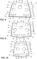
FIG. 8 is a bottom perspective view of another configuration of the second embodiment of the single planar glass substrate of the glass cooktop according to the present disclosure; -
FIG. 9 is a bottom perspective view of yet another configuration of the second embodiment of the single planar glass substrate of the glass cooktop according to the present disclosure; -
FIG. 10 is a bottom perspective view of still another configuration of the second embodiment of the single planar glass substrate of the glass cooktop according to the present disclosure; -
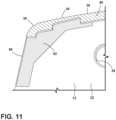
FIG. 11 is a bottom perspective view of a corner and connector of the second embodiment of the single planar glass substrate of the glass cooktop according to the present disclosure; and -
FIG. 12 is a bottom perspective and plan view of a reinforcement of one of the plurality of linear segments of the gasket of the second embodiment of the single planar glass substrate of the glass cooktop according to the present disclosure. - The components in the figures are not necessarily to scale, emphasis instead being placed upon illustrating the principles described herein.
- The present illustrated embodiments reside primarily in combinations of method steps and apparatus components related to a single planar glass substrate of the glass cooktop. Accordingly, the apparatus components and method steps have been represented, where appropriate, by conventional symbols in the drawings, showing only those specific details that are pertinent to understanding the embodiments of the present disclosure so as not to obscure the disclosure with details that will be readily apparent to those of ordinary skill in the art having the benefit of the description herein. Further, like numerals in the description and drawings represent like elements.
- For purposes of description herein, the terms "upper," "lower," "right," "left," "rear," "front," "vertical," "horizontal," and derivatives thereof shall relate to the disclosure as oriented in
FIG. 1 . Unless stated otherwise, the term "front" shall refer to the surface of the element closer to an intended viewer, and the term "rear" shall refer to the surface of the element further from the intended viewer. However, it is to be understood that the disclosure may assume various alternative orientations, except where expressly specified to the contrary. It is also to be understood that the specific devices and processes illustrated in the attached drawings, and described in the following specification are simply exemplary embodiments of the inventive concepts defined in the appended claims. Hence, specific dimensions and other physical characteristics relating to the embodiments disclosed herein are not to be considered as limiting, unless the claims expressly state otherwise. - The terms "including," "comprises," "comprising," or any other variation thereof, are intended to cover a non-exclusive inclusion, such that a process, method, article, or apparatus that comprises a list of elements does not include only those elements but may include other elements not expressly listed or inherent to such process, method, article, or apparatus. An element proceeded by "comprises a ... " does not, without more constraints, preclude the existence of additional identical elements in the process, method, article, or apparatus that comprises the element.
- Referring to
FIGS. 1-12 ,reference numeral 10 generally designates aglass cooktop 10 that includes a singleplanar glass substrate 12. Theglass cooktop 10 may be used in a freestanding device, such as a kitchen range with cooktop and an oven, or as a stand-alone unit mounted directly to akitchen countertop 14, as shown inFIG. 1 . As a stand-alone unit, shown inFIG. 3 , abase 16 of theglass cooktop 10 may be mounted in anopening 18 in thecountertop 14, with abase gasket 20 provided to prevent debris from infiltrating the installation. The singleplanar glass substrate 12 is disposed within arecess 22 on anupper surface 24 of thebase 16 of theglass cooktop 10, as further described below. - As is typical in
such glass cooktops 10, heating elements or induction elements (not shown) may be disposed below theglass cooktop 10 or, as shown,element openings 26 may be provided for the placement of such heating elements or induction elements. Similarly,control openings 28 may be provided to allow the installation of rotary controls (not shown) for turning the heating elements or induction elements on or off and for controlling the intensity of the energy output of the heating elements or induction elements, as is known. Different arrangements of theelement openings 26 and thecontrol openings 28 may be contemplated, as depicted in the Figures. - The single
planar glass substrate 12 includes an upperexterior surface 30 and alower interior surface 32. Aperimeter 34 disposed about anouter edge 36 of the singleplanar glass substrate 12 defines the configuration of the cooktop. That is, theglass cooktop 10 and the singleplanar glass substrate 12 may have a polygonal configuration having a plurality ofcorners 38. As shown in the Figures, the singleplanar glass substrate 12 has a substantially rectilinear configuration having fourcorners 38. However, other configurations may be adopted. - A
gasket 40 may be disposed on theinterior surface 32 of the singleplanar glass substrate 12, wheregasket 40 is disposed radially inward from theperimeter 34 of the singleplanar glass substrate 12, as perhaps best seen inFIG. 3 . The radial inward distance (d) of thegasket 40 may be about 4 mm (+/- 2 mm) from theouter edge 36 of the singleplanar glass substrate 12. Smaller distances are desired. So positioned, thegasket 40 may be adapted to absorb energy associated with a breaking of the singleplanar glass substrate 12, such that a plurality of broken sections of the singleplanar glass substrate 12 are retained by thegasket 40. Thegasket 40 should not be disposed at theouter edge 36 of the singleplanar glass substrate 12. - In a first embodiment shown in
FIGS. 1-6 , thegasket 40 may be fabricated as a bead ofsilicone 42 extending about an entirety of theperimeter 34 of the singleplanar glass substrate 12. Thegasket 40 may also comprise a hot melt adhesive so disposed. Thegasket 40, formed as a bead ofsilicone 42, may have an installed width (w) of about 15 mm and an installed height (h) of about 2 mm, as again shown inFIG. 3 . However, the advantages of the present invention may be also obtained where the bead ofsilicone 42 extends about less than the entirety of theperimeter 34, for example, the bead ofsilicone 42 may be omitted from one side of the singleplanar glass substrate 12, such as arear side 44, which may be less likely to generate broken sections of glass during a breakage event. - The single
planar glass substrate 12 may further include anadditional silicone bead 46 extending between a pair ofopposed sides planar glass substrate 12, as shown inFIGS. 5 and6 . That is, for reinforcement, additional beads ofsilicone 46 may be added as internal links. - An advantageous feature of the present disclosure is the ability to have the
gasket 40 applied robotically as thesilicone bead 42. Such application technique promotes repeatability, reduces the complexity of manufacturing the cooktop, simplifies the overall process, and reduces the application time. - In a second embodiment, shown in
FIGS. 7-12 , a one of a plurality ofconnectors 52 may be disposed at each of the fourcorners 38 of theinterior surface 32 of the singleplanar glass substrate 12. Thegasket 40 again is disposed on theinterior surface 32 radially inward from theperimeter 34 of the singleplanar glass substrate 12. Thegasket 40 may also include a plurality of individuallinear sections 54, as shown inFIGS. 7-10 as four individuallinear sections 54, that each extends between an adjacent pair ofconnectors 52 of the plurality ofconnectors 52. - The individual
linear sections 54 of thegasket 40 may extend about an entirety of theperimeter 34 of the singleplanar glass substrate 12. However, the advantages of the present invention may be also obtained where the individuallinear sections 54 of thegasket 40 extend less than the about an entirety of theperimeter 34, for example, where an individuallinear section 54 of thegasket 40 may be omitted from one side of the singleplanar glass substrate 12, such as therear side 44, which may be less likely to generate broken sections, as shown inFIGS. 8-10 . - Each of the plurality of
connectors 52 may comprise a single-sided adhesive or a double-sided adhesive. Each of the plurality of individuallinear sections 54 of the gasket may comprise a tape adhered to theinterior surface 32 of the singleplanar glass substrate 12, wherein the individuallinear section 54 adhered to theinterior surface 32 of the singleplanar glass substrate 12 may also include a single-sided adhesive or a double-sided adhesive. - As shown in
FIGS. 8-10 , each of the plurality ofconnectors 52 may comprise a plurality of overlapping and angularly displaced tape strips 56, 58. The plurality of overlapping and angularly displaced tape strips 56, 58 may be set substantially orthogonally to each other. As shown inFIG. 9 , the plurality of overlapping and angularly displaced tape strips 56, 58 may also include atape strip 60 set obliquely to each of the tape strips 56, 58 set substantially orthogonally to each other. Alternatively, each of the plurality ofconnectors 52 may have a planar shape conforming to the geometry of each of the plurality ofcorners 38, as shown inFIG. 11 . That is, each of the plurality ofconnectors 52 may have a custom and unique configuration that is formed to match theouter edge 36 of thecorner 38 of theperimeter 34 of the singleplanar glass substrate 12, depending on its specific geometry, that is disposing radially inward from theperimeter 34, as discussed above. - As seen in
FIG. 12 , thegasket 40 may also include a reinforcingstructure 62 in order to avoid high deformation during a breakage event. The reinforcingstructure 62 may include a plurality ofparallel ribs 64 disposed along a longitudinal length of and on aplanar surface 66 of thegasket 40. - In operation, the method of absorbing energy associated with breaking of a single
planar glass substrate 12 of aglass cooktop 10, whereby a plurality of broken sections of the singleplanar glass substrate 12 are retained, includes the step of providing the singleplanar glass substrate 12 having the exposedupper exterior surface 30 and the lowerinterior surface 32. The method also includes the step of disposing thegasket 40 on theinterior surface 32 radially inward the distance (d) from theperimeter 34 disposed about theouter edge 36 of the singleplanar glass substrate 12. The singleplanar glass substrate 12 is then installed on theglass cooktop 10, such that thegasket 40 is adapted to absorb energy and retain the plurality of broken sections in the singleplanar glass substrate 12 in the event of glass breakage. - The step of disposing the
gasket 40 on theinterior surface 32 radially inward from aperimeter 34 disposed about anouter edge 36 of the singleplanar glass substrate 12 may be obtained by applying thegasket 40 as the bead ofsilicone 42 about an entirety of theperimeter 34 robotically. - The method may further comprise the step of disposing the plurality of
connectors 52 on each of the plurality ofcorners 38 of theinterior surface 32 of the singleplanar glass substrate 12, such that thegasket 40 is disposed on theinterior surface 32 radially inward from theperimeter 34 of the singleplanar glass substrate 12, and wherein thegasket 40 includes the plurality of individuallinear sections 54 that each extends between an adjacent pair of the plurality ofconnectors 52. - As disclosed above, an objective is to contain glass shards or chips generated by a breakage of the
glass cooktop 10 that might otherwise be directed toward a user of theglass cooktop 10 by retaining such glass shards or chips by thegasket 40. In the first embodiment, thegasket 40 formed as a silicone/hot meltadhesive bead 42 on the singleplanar glass substrate 12 absorbs the breakage energy, mitigating the hazard of fragments flying away from theglass cooktop 10. In the second embodiment, thegasket 40 is in the form of a plurality of individuallinear sections 54 of single-sided tape or double-sided tape that each extends between adjacent twoconnectors 52 of the plurality ofconnectors 52, that may also be fabricated by single-sided tape or double-sided tape.
Claims (15)
- A glass cooktop (10) comprising a single planar glass substrate (12), wherein the single planar glass substrate (12) further comprises;an exposed upper surface (24);an interior lower surface (32);a perimeter (34) disposed about an outer edge (36) of the single planar glass substrate (12); anda gasket (40) disposed on the interior surface (32) radially inward from the perimeter (34) of the single planar glass substrate (12);wherein the gasket (40) is adapted to absorb energy associated with a breaking of the single planar glass substrate (12) such that a plurality of broken sections of the single planar glass substrate (12) are retained by the gasket (40).
- The glass cooktop of claim 1, wherein the gasket (40) comprises a bead of silicone (42), and the bead of silicone (42) preferably extends about an entirety of the perimeter (34).
- The glass cooktop of claims 1 or 2, wherein single planar glass substrate (12) further includes a silicone bead (42) extending between a pair of opposed sides (48, 50) of single planar glass substrate (12), and wherein the silicone bead (42) is preferably applied robotically.
- The glass cooktop of any of claims 1 through 3, wherein the single planar glass substrate (12) has a substantially rectilinear configuration having four corners (38); and
wherein a one of a plurality of connectors (52) is disposed at each of the four corners (38) of the interior surface (32) of the single planar glass substrate (12). - The glass cooktop of claim 4, wherein the gasket (40) disposed on the interior surface (32) radially inward from the perimeter (34) of the single planar glass substrate (12) comprises four individual linear sections (54) that each extend between an adjacent two connectors (52) of the plurality of connectors (52).
- The glass cooktop of claims 4 or 5, wherein the each of the plurality of connectors (52) comprise a single-sided adhesive or a double-sided adhesive.
- The glass cooktop of any of claims 1 through 6, wherein the gasket (40) comprises a tape strip (56, 58) adhered to the interior surface (32) of the single planar glass substrate (12).
- A glass cooktop (10) comprising a single planar glass substrate (12), wherein the single planar glass substrate (12) further comprises:an exterior surface (30) and an interior surface (32) defining a polygonal configuration having a plurality of corners (38);a plurality of connectors (52) disposed on each of the plurality of corners (38) of the interior surface (32) of the single planar glass substrate (12); anda gasket (40) disposed on the interior surface (32) radially inward from a perimeter (34) of the single planar glass substrate (12), wherein the gasket (40) includes a plurality of individual linear sections (54) that each extend between an adjacent pair of the plurality of connectors (52).
- The glass cooktop of claim 8, wherein the plurality of connectors (52) comprises a single-sided adhesive or a double-sided adhesive and the gasket (40) comprises a tape adhered to the interior surface (32) of the single planar glass substrate (12) by a single-sided adhesive or a double-sided adhesive.
- The glass cooktop of any of claims 8 through 9, wherein each of the plurality of connectors (52) further comprises:a plurality of overlapping and angularly displaced tape strips (56, 58); ora planar shape conforming to a geometry of a one each of the plurality of corners (38).
- The glass cooktop of any of claims 8 through 10, wherein the plurality of overlapping and angularly displaced tape strips (56, 58):are set substantially orthogonally to each other; orinclude a tape strip set (60) set obliquely to each of the tape strips (56, 58) set substantially orthogonally to each other.
- The glass cooktop of any of claims 8 through 11, wherein the gasket further comprises a reinforcing structure (62) comprising a plurality of parallel ribs (64) disposed along a longitudinal length of and on a planar surface (66) of the gasket (40).
- A method of absorbing energy associated with breaking a single planar glass substrate (12) of a cooktop (10), whereby a plurality of broken sections of the single planar glass substrate (12) are retained, the method comprising the steps of:providing the single planar glass substrate (12) having an exposed upper exterior surface (24) and a lower interior surface (32);disposing a gasket (40) on the interior surface (32) radially inward from a perimeter (34) disposed about an outer edge (36) of the single planar glass substrate (12); andinstalling the single planar glass substrate (12) on the cooktop (10), such that the gasket (40) is adapted to absorb energy and retain the plurality of broken sections in the single planar glass substrate (12) in the event of glass breakage.
- The method of claim 13, wherein the step of disposing the gasket (40) on the interior surface (32) radially inward from a perimeter (34) disposed about an outer edge of the single planar glass substrate (12) is obtained by applying the gasket (40) as a bead of silicone about an entirety of the perimeter (34) robotically.
- The method of claims 12 or 13, further comprising the step of disposing a plurality of connectors (52) on each of a plurality of corners (38) of the interior surface (32) of the single planar glass substrate (12), such that the gasket (40) is disposed on the interior surface (32) radially inward from the perimeter (34) of the single planar glass substrate (12) , and wherein the gasket (40) includes a plurality of individual linear sections (54) that each extend between an adjacent pair of the plurality of connectors (52).
Applications Claiming Priority (1)
| Application Number | Priority Date | Filing Date | Title |
|---|---|---|---|
| US17/591,973 US12553617B2 (en) | 2022-02-03 | 2022-02-03 | Glass breakage mitigation using silicone rubber or similar material |
Publications (1)
| Publication Number | Publication Date |
|---|---|
| EP4224069A1 true EP4224069A1 (en) | 2023-08-09 |
Family
ID=85173955
Family Applications (1)
| Application Number | Title | Priority Date | Filing Date |
|---|---|---|---|
| EP23154983.3A Withdrawn EP4224069A1 (en) | 2022-02-03 | 2023-02-03 | Glass breakage mitigation using silicone rubber or similar material |
Country Status (2)
| Country | Link |
|---|---|
| US (1) | US12553617B2 (en) |
| EP (1) | EP4224069A1 (en) |
Citations (2)
| Publication number | Priority date | Publication date | Assignee | Title |
|---|---|---|---|---|
| US5768979A (en) * | 1994-11-02 | 1998-06-23 | Seb S.A. | Process for assembling a cooking unit plate with its support and resulting cooking unit |
| WO2006104825A2 (en) * | 2005-03-25 | 2006-10-05 | Henkel Corporation | Compositions and processes for assembling appliances |
Family Cites Families (16)
| Publication number | Priority date | Publication date | Assignee | Title |
|---|---|---|---|---|
| DE3472132D1 (en) * | 1983-12-16 | 1988-07-21 | Kasei Co C I | Joint sealing member |
| US5185047A (en) | 1989-12-01 | 1993-02-09 | Whirlpool Corporation | Frameless glass-ceramic cooktop mounting assembly |
| US5571434A (en) * | 1994-06-29 | 1996-11-05 | Whirlpool Corporation | Cooktop stamping having means for attaching heating elements and an integral trim ring |
| US5551103A (en) * | 1994-08-17 | 1996-09-03 | Drozdowich; Bryan G. | Apertured countertop mounting unit |
| DE19912452B4 (en) | 1999-03-19 | 2007-10-25 | BSH Bosch und Siemens Hausgeräte GmbH | Built-in bar for a hob |
| US7351379B2 (en) * | 2002-06-14 | 2008-04-01 | Agilent Technologies, Inc. | Fluid containment structure |
| WO2005084253A2 (en) | 2004-03-02 | 2005-09-15 | M Management-Tex, Ltd. | Cooktop gasket |
| US7881593B2 (en) | 2007-11-16 | 2011-02-01 | Cfom Inc. | Gas cooking appliance with removable burners and useable work area |
| EP2626638B1 (en) | 2010-10-05 | 2018-08-01 | Shibaura Electronics Co., Ltd. | Cooking device |
| CN104703793B (en) | 2012-06-01 | 2018-09-18 | 康宁股份有限公司 | Glass laminate construction for optimized breakability |
| WO2014142130A1 (en) | 2013-03-13 | 2014-09-18 | パナソニックヘルスケア株式会社 | Cool box, control method for cool box, and control program for cool box |
| CN203815463U (en) | 2014-04-09 | 2014-09-10 | 沙福禄 | Low-temperature atomizing trace visualizing instrument |
| CN104075519A (en) | 2014-07-22 | 2014-10-01 | 合肥晶弘电器有限公司 | Refrigerator with warm-keeping chamber and temperature controlling method of warm-keeping chamber |
| WO2016082894A1 (en) | 2014-11-28 | 2016-06-02 | Arcelik Anonim Sirketi | Framework for installing built-in type cooking appliance |
| US20170023258A1 (en) | 2015-07-22 | 2017-01-26 | General Electric Company | Panel assemblies for appliances |
| KR101744918B1 (en) | 2015-09-02 | 2017-06-08 | (주)쿠첸 | Structure for mounting cover glass on electric range |
-
2022
- 2022-02-03 US US17/591,973 patent/US12553617B2/en active Active
-
2023
- 2023-02-03 EP EP23154983.3A patent/EP4224069A1/en not_active Withdrawn
Patent Citations (2)
| Publication number | Priority date | Publication date | Assignee | Title |
|---|---|---|---|---|
| US5768979A (en) * | 1994-11-02 | 1998-06-23 | Seb S.A. | Process for assembling a cooking unit plate with its support and resulting cooking unit |
| WO2006104825A2 (en) * | 2005-03-25 | 2006-10-05 | Henkel Corporation | Compositions and processes for assembling appliances |
Also Published As
| Publication number | Publication date |
|---|---|
| US20230243514A1 (en) | 2023-08-03 |
| US12553617B2 (en) | 2026-02-17 |
Similar Documents
| Publication | Publication Date | Title |
|---|---|---|
| JP6270167B2 (en) | Vacuum insulating glass (VIG) window unit including exhaust pipe protection ring and / or cap, and method for manufacturing the same | |
| US9388990B2 (en) | Metal panel, manufacturing method thereof and cooking device using the metal panel | |
| KR100670252B1 (en) | Chassis base assembly, method for manufacturing same, and plasma display assembly using the same | |
| WO2003071964A3 (en) | Panel element with a heating layer | |
| US20130074445A1 (en) | Vacuum insulating glass (vig) unit pump-out tube protecting techniques, and/or vig units incorporating the same | |
| US6281480B1 (en) | Installation strip for a cooktop | |
| MX2013001572A (en) | Window pane having an antenna. | |
| KR102081644B1 (en) | Cooktop with window and end plate, cooking appliance, and method for manufacturing the cooktop | |
| US12553617B2 (en) | Glass breakage mitigation using silicone rubber or similar material | |
| US6313447B1 (en) | Cook top positioning element for a heating device | |
| US20120167866A1 (en) | Window mounting for thermal expansion in an oven appliance | |
| KR101453307B1 (en) | Vacuum glass panel module | |
| US10107503B2 (en) | Cooktop with window and end plate, cooking appliance, and method for manufacturing the cooktop | |
| KR20160038337A (en) | Assembly for clamping top plate to induction range body | |
| EP0111367A2 (en) | Double glass covering and procedure allowing to realize such a double glass covering | |
| CN101687395B (en) | Devices for securing secure glass-covered components | |
| KR101407318B1 (en) | Vacuum glass panel module and method for manufacturing the same | |
| KR20180061676A (en) | Heating plate, dielectric assembly having the same and substrate processing apparatus having the same | |
| US6276357B1 (en) | Cooktop with a cooktop frame | |
| CA2349316A1 (en) | Method and apparatus for protecting a stove control panel from splatter | |
| EP4273453A1 (en) | Electric cooktop assembly | |
| JP4064881B2 (en) | High frequency heating device | |
| KR101296488B1 (en) | Backlight Unit and Assembling Method therof | |
| JP2000320004A (en) | Building unit, its manufacturing method and unit building | |
| CN218772206U (en) | Liquid crystal display television backlight control system |
Legal Events
| Date | Code | Title | Description |
|---|---|---|---|
| PUAI | Public reference made under article 153(3) epc to a published international application that has entered the european phase |
Free format text: ORIGINAL CODE: 0009012 |
|
| STAA | Information on the status of an ep patent application or granted ep patent |
Free format text: STATUS: THE APPLICATION HAS BEEN PUBLISHED |
|
| AK | Designated contracting states |
Kind code of ref document: A1 Designated state(s): AL AT BE BG CH CY CZ DE DK EE ES FI FR GB GR HR HU IE IS IT LI LT LU LV MC ME MK MT NL NO PL PT RO RS SE SI SK SM TR |
|
| STAA | Information on the status of an ep patent application or granted ep patent |
Free format text: STATUS: THE APPLICATION IS DEEMED TO BE WITHDRAWN |
|
| 18D | Application deemed to be withdrawn |
Effective date: 20240210 |