EP4224053A1 - Support structural members and display apparatus - Google Patents
Support structural members and display apparatus Download PDFInfo
- Publication number
- EP4224053A1 EP4224053A1 EP21922406.0A EP21922406A EP4224053A1 EP 4224053 A1 EP4224053 A1 EP 4224053A1 EP 21922406 A EP21922406 A EP 21922406A EP 4224053 A1 EP4224053 A1 EP 4224053A1
- Authority
- EP
- European Patent Office
- Prior art keywords
- support
- display panel
- flexible display
- drive
- main body
- Prior art date
- Legal status (The legal status is an assumption and is not a legal conclusion. Google has not performed a legal analysis and makes no representation as to the accuracy of the status listed.)
- Pending
Links
Images




Classifications
-
- G—PHYSICS
- G06—COMPUTING OR CALCULATING; COUNTING
- G06F—ELECTRIC DIGITAL DATA PROCESSING
- G06F1/00—Details not covered by groups G06F3/00 - G06F13/00 and G06F21/00
- G06F1/16—Constructional details or arrangements
- G06F1/1613—Constructional details or arrangements for portable computers
- G06F1/1615—Constructional details or arrangements for portable computers with several enclosures having relative motions, each enclosure supporting at least one I/O or computing function
- G06F1/1624—Constructional details or arrangements for portable computers with several enclosures having relative motions, each enclosure supporting at least one I/O or computing function with sliding enclosures, e.g. sliding keyboard or display
-
- F—MECHANICAL ENGINEERING; LIGHTING; HEATING; WEAPONS; BLASTING
- F16—ENGINEERING ELEMENTS AND UNITS; GENERAL MEASURES FOR PRODUCING AND MAINTAINING EFFECTIVE FUNCTIONING OF MACHINES OR INSTALLATIONS; THERMAL INSULATION IN GENERAL
- F16M—FRAMES, CASINGS OR BEDS OF ENGINES, MACHINES OR APPARATUS, NOT SPECIFIC TO ENGINES, MACHINES OR APPARATUS PROVIDED FOR ELSEWHERE; STANDS; SUPPORTS
- F16M11/00—Stands or trestles as supports for apparatus or articles placed thereon ; Stands for scientific apparatus such as gravitational force meters
- F16M11/02—Heads
- F16M11/04—Means for attachment of apparatus; Means allowing adjustment of the apparatus relatively to the stand
- F16M11/043—Allowing translations
-
- F—MECHANICAL ENGINEERING; LIGHTING; HEATING; WEAPONS; BLASTING
- F16—ENGINEERING ELEMENTS AND UNITS; GENERAL MEASURES FOR PRODUCING AND MAINTAINING EFFECTIVE FUNCTIONING OF MACHINES OR INSTALLATIONS; THERMAL INSULATION IN GENERAL
- F16M—FRAMES, CASINGS OR BEDS OF ENGINES, MACHINES OR APPARATUS, NOT SPECIFIC TO ENGINES, MACHINES OR APPARATUS PROVIDED FOR ELSEWHERE; STANDS; SUPPORTS
- F16M11/00—Stands or trestles as supports for apparatus or articles placed thereon ; Stands for scientific apparatus such as gravitational force meters
- F16M11/02—Heads
- F16M11/04—Means for attachment of apparatus; Means allowing adjustment of the apparatus relatively to the stand
- F16M11/043—Allowing translations
- F16M11/045—Allowing translations adapted to left-right translation movement
-
- F—MECHANICAL ENGINEERING; LIGHTING; HEATING; WEAPONS; BLASTING
- F16—ENGINEERING ELEMENTS AND UNITS; GENERAL MEASURES FOR PRODUCING AND MAINTAINING EFFECTIVE FUNCTIONING OF MACHINES OR INSTALLATIONS; THERMAL INSULATION IN GENERAL
- F16M—FRAMES, CASINGS OR BEDS OF ENGINES, MACHINES OR APPARATUS, NOT SPECIFIC TO ENGINES, MACHINES OR APPARATUS PROVIDED FOR ELSEWHERE; STANDS; SUPPORTS
- F16M11/00—Stands or trestles as supports for apparatus or articles placed thereon ; Stands for scientific apparatus such as gravitational force meters
- F16M11/02—Heads
- F16M11/18—Heads with mechanism for moving the apparatus relatively to the stand
-
- F—MECHANICAL ENGINEERING; LIGHTING; HEATING; WEAPONS; BLASTING
- F16—ENGINEERING ELEMENTS AND UNITS; GENERAL MEASURES FOR PRODUCING AND MAINTAINING EFFECTIVE FUNCTIONING OF MACHINES OR INSTALLATIONS; THERMAL INSULATION IN GENERAL
- F16M—FRAMES, CASINGS OR BEDS OF ENGINES, MACHINES OR APPARATUS, NOT SPECIFIC TO ENGINES, MACHINES OR APPARATUS PROVIDED FOR ELSEWHERE; STANDS; SUPPORTS
- F16M13/00—Other supports for positioning apparatus or articles; Means for steadying hand-held apparatus or articles
-
- G—PHYSICS
- G06—COMPUTING OR CALCULATING; COUNTING
- G06F—ELECTRIC DIGITAL DATA PROCESSING
- G06F1/00—Details not covered by groups G06F3/00 - G06F13/00 and G06F21/00
- G06F1/16—Constructional details or arrangements
- G06F1/1601—Constructional details related to the housing of computer displays, e.g. of CRT monitors, of flat displays
-
- G—PHYSICS
- G06—COMPUTING OR CALCULATING; COUNTING
- G06F—ELECTRIC DIGITAL DATA PROCESSING
- G06F1/00—Details not covered by groups G06F3/00 - G06F13/00 and G06F21/00
- G06F1/16—Constructional details or arrangements
- G06F1/1613—Constructional details or arrangements for portable computers
- G06F1/1633—Constructional details or arrangements of portable computers not specific to the type of enclosures covered by groups G06F1/1615 - G06F1/1626
- G06F1/1637—Details related to the display arrangement, including those related to the mounting of the display in the housing
-
- G—PHYSICS
- G06—COMPUTING OR CALCULATING; COUNTING
- G06F—ELECTRIC DIGITAL DATA PROCESSING
- G06F1/00—Details not covered by groups G06F3/00 - G06F13/00 and G06F21/00
- G06F1/16—Constructional details or arrangements
- G06F1/1613—Constructional details or arrangements for portable computers
- G06F1/1633—Constructional details or arrangements of portable computers not specific to the type of enclosures covered by groups G06F1/1615 - G06F1/1626
- G06F1/1637—Details related to the display arrangement, including those related to the mounting of the display in the housing
- G06F1/1652—Details related to the display arrangement, including those related to the mounting of the display in the housing the display being flexible, e.g. mimicking a sheet of paper, or rollable
-
- G—PHYSICS
- G06—COMPUTING OR CALCULATING; COUNTING
- G06F—ELECTRIC DIGITAL DATA PROCESSING
- G06F1/00—Details not covered by groups G06F3/00 - G06F13/00 and G06F21/00
- G06F1/16—Constructional details or arrangements
- G06F1/1613—Constructional details or arrangements for portable computers
- G06F1/1633—Constructional details or arrangements of portable computers not specific to the type of enclosures covered by groups G06F1/1615 - G06F1/1626
- G06F1/1675—Miscellaneous details related to the relative movement between the different enclosures or enclosure parts
- G06F1/1677—Miscellaneous details related to the relative movement between the different enclosures or enclosure parts for detecting open or closed state or particular intermediate positions assumed by movable parts of the enclosure, e.g. detection of display lid position with respect to main body in a laptop, detection of opening of the cover of battery compartment
-
- G—PHYSICS
- G06—COMPUTING OR CALCULATING; COUNTING
- G06F—ELECTRIC DIGITAL DATA PROCESSING
- G06F1/00—Details not covered by groups G06F3/00 - G06F13/00 and G06F21/00
- G06F1/16—Constructional details or arrangements
- G06F1/1613—Constructional details or arrangements for portable computers
- G06F1/1633—Constructional details or arrangements of portable computers not specific to the type of enclosures covered by groups G06F1/1615 - G06F1/1626
- G06F1/1675—Miscellaneous details related to the relative movement between the different enclosures or enclosure parts
- G06F1/1681—Details related solely to hinges
-
- H—ELECTRICITY
- H04—ELECTRIC COMMUNICATION TECHNIQUE
- H04M—TELEPHONIC COMMUNICATION
- H04M1/00—Substation equipment, e.g. for use by subscribers
- H04M1/02—Constructional features of telephone sets
- H04M1/0202—Portable telephone sets, e.g. cordless phones, mobile phones or bar type handsets
- H04M1/0206—Portable telephones comprising a plurality of mechanically joined movable body parts, e.g. hinged housings
- H04M1/0208—Portable telephones comprising a plurality of mechanically joined movable body parts, e.g. hinged housings characterized by the relative motions of the body parts
- H04M1/0235—Slidable or telescopic telephones, i.e. with a relative translation movement of the body parts; Telephones using a combination of translation and other relative motions of the body parts
- H04M1/0237—Sliding mechanism with one degree of freedom
-
- H—ELECTRICITY
- H04—ELECTRIC COMMUNICATION TECHNIQUE
- H04M—TELEPHONIC COMMUNICATION
- H04M1/00—Substation equipment, e.g. for use by subscribers
- H04M1/02—Constructional features of telephone sets
- H04M1/0202—Portable telephone sets, e.g. cordless phones, mobile phones or bar type handsets
- H04M1/026—Details of the structure or mounting of specific components
- H04M1/0266—Details of the structure or mounting of specific components for a display module assembly
- H04M1/0268—Details of the structure or mounting of specific components for a display module assembly including a flexible display panel
-
- F—MECHANICAL ENGINEERING; LIGHTING; HEATING; WEAPONS; BLASTING
- F16—ENGINEERING ELEMENTS AND UNITS; GENERAL MEASURES FOR PRODUCING AND MAINTAINING EFFECTIVE FUNCTIONING OF MACHINES OR INSTALLATIONS; THERMAL INSULATION IN GENERAL
- F16M—FRAMES, CASINGS OR BEDS OF ENGINES, MACHINES OR APPARATUS, NOT SPECIFIC TO ENGINES, MACHINES OR APPARATUS PROVIDED FOR ELSEWHERE; STANDS; SUPPORTS
- F16M2200/00—Details of stands or supports
- F16M2200/02—Locking means
Definitions
- the present disclosure relates to the technical field of a display device, and in particular, to a support structural member and a display device.
- a flexible screen is usually combined with a flexible screen support structure, and the flexible screen support structure is used to realize bending or folding of the flexible screen.
- flexible screens have advantages, such as lightness and thinness, low power consumption, and as flexible screens are bendable and flexible, their application scenarios are becoming more and more extensive.
- a sliding mechanism directly acts on a screen body, which will lead to excessive force on the screen body and affect the service life of the screen body.
- the present disclosure provides a support structural member and a display device, aiming to provide a good support to a flexible display panel and improve the service life of the flexible display panel.
- a first aspect of the present disclosure provides a support structural member for a flexible display panel, comprising: a main body support member, comprising a bearing portion for bearing a part of the flexible display panel; a sliding support member, movably connected to the main body support member along a second direction, wherein the sliding support member comprises a first support portion and a second support portion spaced along a first direction, and the first support portion extends beyond the main body support member and supports the flexible display panel together with the bearing portion; a pushing member, movably connected to the second support portion along the second direction, wherein the pushing member comprises a stopper, and the stopper protrudes from a support surface of the second support portion for supporting the flexible display panel, so the stopper stops an end of the flexible display panel and pushes the flexible display panel to move.
- a second aspect of the present disclosure provides a display device, comprising: the support structural member of any one of the above embodiments; a flexible display panel, comprising a first end and a second end opposite to each other, wherein the first end is connected to the main body support member, the second end is located on the second support portion and is stopped by the stopper, so the stopper can push the second end to move in a direction away from the main body support member.
- the support structural member includes the main body support member, the sliding support member and the pushing member.
- the sliding support member is movably connected to the main support member along the second direction.
- the first support portion of the sliding support member can support the flexible display panel together with the bearing portion of the main body support member, so as to increase a display area and realize large-screen display.
- the stopper of the pushing member is arranged on the second support portion of the sliding support member, and the stopper protrudes from the support surface of the second support portion, so that the stopper can stop an end of the flexible display panel.
- the flexible display panel can be pushed to move by the stopper, so that a part of the flexible display panel folded on a second side is moved to a first side.
- the stopper acts on the end of the flexible display panel instead of the surface of the flexible display panel, which can reduce the stress on the flexible display panel and improve the service life of the display panel.
- FIGS. 1 to 13 For a better understanding of the present disclosure, a support structural member and a display device of embodiments of the present disclosure will be described in detail below with reference to FIGS. 1 to 13 .
- a display device includes a flexible display panel 10 and a support structural member 20.
- the support structural member 20 is used to provide support for the flexible display panel 10.
- the display device includes a first side AA1 and a second side AA2 disposed opposite to each other in a first direction (Z direction in FIG. 1 ).
- the display device in the embodiment of the present disclosure includes but are not limited to a mobile phone, a personal digital assistant (Personal Digital Assistant, PDA for short), a tablet computer, an e-book, a television, access control, a smart fixed phone, a console, and other devices with display functions.
- a mobile phone a personal digital assistant (Personal Digital Assistant, PDA for short)
- PDA Personal Digital Assistant
- a tablet computer an e-book
- a television access control
- a smart fixed phone a console
- other devices with display functions include but are not limited to a mobile phone, a personal digital assistant (Personal Digital Assistant, PDA for short), a tablet computer, an e-book, a television, access control, a smart fixed phone, a console, and other devices with display functions.
- PDA Personal Digital Assistant
- the flexible display panel 10 can be bent and the support structural member 20 can be retracted, and at least part of the flexible display panel 10 can be bent and extends to the second side AA2 of the support structural member 20.
- the flexible display panel 10 located on the second side AA2 can move to the first side AA1, thereby increasing the display area of the display device.
- the size of the display device in the second direction increases, the display area of the flexible display panel 10 on the first side AA1 increases, and a displayable area of the display device increases.
- the flexible display panel 10 includes a first end 11 and a second end 12 opposite to each other, the first end 11 is located on the first side AA1, and the second end 12 is located on the second side AA2, so that a part of the flexible display panel 10 is located on the first side AA1, and the other part of the flexible display panel 10 is bent and extends to the second side AA2 of the support structural member 20.
- FIG. 3 In order to better show the relative positional relationship between the support structural member 20 and the flexible display panel 10 when the support structural member 20 is used to support the flexible display panel 10, the structure of the support structural member 20 is shown in FIG. 3 .
- the support structural member 20 for supporting the flexible display panel 10.
- the support structural member 20 includes the main body support member 100, the sliding support member 200 movably connected to the main body support member 100 along the second direction, and the pushing member 300 movably connected to the sliding support member 200 along the second direction.
- the main body support member 100 includes a bearing portion 110 for bearing a part of the flexible display panel 10.
- the sliding support member 200 includes a first support portion 210 and a second support portion 220 spaced along the first direction, the first support part 210 is used to extend beyond the main body support member 100 and support the flexible display panel 10 together with the bearing portion 110.
- the pushing member 300 is movably connected to the second support portion 220 along the second direction.
- the pushing member 300 includes a stopper 310, and the stopper 310 protrudes from the support surface of the second support portion 220 for supporting the flexible display panel 10, so that the stopper 310 can stop an end of the flexible display panel 10 and push the flexible display panel 10 to move.
- the first support portion 210 of the sliding support member 200 can support the flexible display panel 10 together with the bearing portion 110 of the main body support member 100, so as to increase the display area and realize large-screen display.
- the stopper 310 of the pushing member 300 is disposed on the second support portion 220 of the sliding support member 200, and the stopper 310 protrudes from the support surface of the second support portion 220, so that the stopper 310 can stop an end of the flexible display panel 10.
- the stopper 310 may stop the second end 12 of the flexible display panel 10.
- the flexible display panel 10 can be pushed to move by the stopper 310, so that the part of the flexible display panel 10 folded and disposed on the second side AA2 moves to the first side AA1.
- one end of the flexible display panel 10 is pushed to realize the large-screen display, and the stopper 310 acts on one end of the flexible display panel 10 instead of the surface of the flexible display panel 10, which can reduce the force on the flexible display panel 10 and increase the service life of the flexible display panel 10.
- the support structural member 20 further includes a guard component 600.
- the guard component 600 is disposed on outer surfaces of both the main body support member 100 and the sliding support member 200, and the guard component 600 is spaced apart from the body support member 100 and the sliding support member 200, so that the flexible display panel 10 can be located between the main body support member 100, the sliding support member 200 and the guard component 600.
- the support structural member 20 further includes a back cover 700 connected to the guard component 600 and located on the second side AA2.
- the back cover 700 is provided with components such as a camera.
- the back cover 700 is connected to the guard component 600 and encloses a protective cavity is with the guard component 600.
- Other components of the support structure 20 and the flexible display panel 10 are located in the protective cavity.
- the guard component 600 includes a first guard portion 610 disposed on the main body support member 100 and a second guard portion 620 disposed on the sliding support member 200.
- a visible window 630 is formed between the first guard portion 610 and the second guard portion 620.
- the flexible display panel 10 can be exposed from the visible window 630, and a user views the display screen of the flexible display panel 10 from the visible window 630.
- the second guard portion 620 moves with the sliding support member 200.
- the second guard portion 620 is wrapped around an outer periphery of the transitional connection portion 230.
- a first limiting member 231 and a second limiting member 232 are disposed in the transition connection portion 230.
- a gap is formed between the first limiting member 231 and the second limiting member 232, and the flexible display panel 10 passes through the gap between the first limiting member 231 and the second limiting member 232.
- the pushing member 300 includes a main body portion 320.
- the main body portion 320 has a bearing surface for bearing the flexible display panel 10, and the stopper 310 is provided on the main body portion 320 and protruding from the bearing surface.
- a plurality of stoppers 310 are distributed at intervals along the third direction (the Y direction in FIG. 3 ) on the main body portion 320, so that the stoppers 310 can stop different parts of the second end 12 in the third direction.
- the support structural member 20 has a retracted state and a deployed state.
- part of the second support portion 220 and the bearing portion 110 are stacked along the first direction, and the size of the support structural member 20 in the second direction is smaller.
- the sliding support member 200 moves in a direction away from the main body support member 100, and at least part of the second support portion 220 protrudes from the bearing portion 110.
- the size of the support structural member 20 in the retracted state is smaller than its dimension in the deployed state. That is, when the support structural member 20 is transformed from the retracted state to the deployed state, the size of the support structural member 20 in the second direction will increase.
- the support structural member 20 provided according to the embodiment of the present disclosure further includes a drive component 400.
- the drive component 400 is used to drive the sliding support member 200 to move relative to the main body support member 100 and to drive the pushing member 300 to move relative to the second support portion 220.
- the drive component 400 When the pushing member 300 pushes the second end 12 of the flexible display panel 10 to move, that is, when the flexible display panel 10 is gradually deployed from the folded state, the drive component 400 also drives the sliding support member 200 to move in a direction away from the main body support member 100, thereby improving the friction damage to the flexible display panel 10 caused by the flexible display panel 10 driving the sliding support member 200 to move, and further improving the service life of the flexible display panel 10.
- the flexible display panel 10 is U-shaped in the folded state
- the drive component 400 drives the sliding support member 200 to move relative to the main body support 100 at a first speed V1
- the drive component 400 drives the pushing member 300 to move relative to the second support portion 220 at a second speed V2.
- the moving distance of the second end 12 of the flexible display panel 10 on the second side AA2 is 2L.
- the ratio of the first speed V1 to the second speed V2 is 1:2
- the distance moved by the pushing member 300 is twice the distance moved by the sliding support member 200 in the same time period.
- the flexible display panel 10 extends from the main body support member 100 at a speed close to the speed at which the sliding support member 200 extends from the main body support member 100. The distance of the flexible display panel 10 extending beyond the main body support member 100 is equal to the moving distance of the sliding support member 200.
- the sliding support member 200 further includes the transition connection portion 230 on its side away from the main body support member 100, and the first support portion 210 and the second support portion 220 are connected to each other via the transition connection portion 230.
- the flexible display panel 10 extends to the second support portion 220 around the transitional connection portion 230.
- the support structural member 20 When the support structural member 20 is transformed from the retracted state to the deployed state, as the speed at which the flexible display panel 10 extends from the main body support member 100 is close to the speed at which the sliding support member 200 extends from the main body support member 100 in the same time period, the distance of the flexible display panel 10 protruding from the main body support member 100 is equal to the moving distance of the sliding support member 200, the stability of the distance between the flexible display panel 10 and the transitional connection portion 230 is ensured and the friction damage of the transitional connection portion 230 to the flexible display panel 10 is improved and the service life of the flexible display panel 10 is increased.
- the flexible display panel 10 is wavy in the folded state, a part of the flexible display panel 10 is located on the first side AA1, and the other part bypasses the sliding support member 200 and is U-shaped or wavy on the second side AA2.
- the second speed V2 is an integer multiple of the first speed V1.
- the flexible display panel 10 when the flexible display panel 10 is in a wavy shape in the folded state, a part of the flexible display panel 10 is located on the first side AA1, and the other part bypasses the sliding support member 200 and is U-shaped on the second side AA2.
- the flexible display panel 10 In the folded state, the flexible display panel 10 is in a three-folded state, and the flexible display panel 10 in the folded state includes three layers stacked in the first direction, so the second speed V2 is three times the first speed V1.
- the speed at which the flexible display panel 10 extends from the main body support member 100 is close to the speed at which the sliding support member 200 extends from the main body support member 100, thereby ensuring the stability of the distance between the flexible display panel 10 and the transition connection portion 230, improving the friction damage to the flexible display panel 10 caused by the transition connection portion 230, and further improving the service life of the flexible display panel 10 .
- the drive component 400 can be arranged in various manners.
- the drive component 400 may be a motor, and the motor drives the pushing member 300 and the stopper 310 to move.
- the drive component 400 includes a first driving group 410 and a second drive group 420.
- the first drive group 410 includes a first drive wheel 411 and a first rack 412 that are engaged with each other.
- the first rack 412 is connected to the stopper 310 and is extended and formed in the second direction.
- the second drive group 420 includes a second drive wheel 421 and a second rack 422 that are engaged with each other.
- the second rack 422 is connected to the second support portion 220 and is extended and formed in the second direction.
- the second drive wheel 421 and the first drive wheel 411 are engaged with each other.
- the first drive group 410 drives the stopper 310 to move via the first drive wheel 411 and the first rack 412.
- the second drive group 420 drives the sliding support member 200 to move via the second drive wheel 421 and the second rack 422.
- the first drive wheel 411 and the second drive wheel 421 are engaged with each other, so that the first drive wheel 411 and the second drive wheel 421 can be linked together.
- the second drive wheel 421 also pushes the sliding support member 200 to move via the second rack 422.
- the second drive wheel 421 includes a first gear 421a and a second gear 421b coaxially arranged, the first gear 421a and the first drive wheel 411 are engaged with each other, and the second gear 421b and the second rack 422 are engaged with each other.
- the radius of the first gear 421a is an integer multiple of the radius of the second gear 421b.
- the second drive wheel 421 includes the first gear 421a and the second gear 421b, and the first gear 421a and the first drive wheel 411 are engaged with each other, so the rotational speeds of the first gear 421a and the first drive wheel 411 are equal, and the rotational distances of the first gear 421a and the first drive wheel 411 are equal.
- the second gear 421b and the second rack 422 are engaged with each other, and the second gear 421b is used to drive the second rack 422 to be engaged with each other.
- the radius of the first gear 421a is an integer multiple of the radius of the second gear 421b, so the rotation distance of the first gear 421a is an integer multiple of the rotation distance of the second gear 421b, and the second speed V2 is an integer multiple of the first speed V1.
- the ratio of the second speed V2 to the first speed V1 is equal to the ratio of the radius of the first gear to the radius of the second gear.
- the radius of the first gear 421a is twice the radius of the second gear 421b.
- the rotational distance of the first gear 421a is twice the rotational distance of the second gear 421b in the same time period, so that the second speed V2 is twice the first speed V1.
- the radius of the first gear 421a is three times the radius of the second gear 421b, and the first gear 421a rotates at the same time
- the distance is three times the rotational distance of the second gear 421b, so that the second speed V2 is three times the first speed V1.
- the drive component 400 of the embodiment of the present disclosure has a simple structure and is convenient to be implemented, and the purpose of reducing the weight of the display device can be achieved and the installation can be simplified.
- the first drive group 410 is an active drive group.
- the first drive wheel 411 in the first drive group 410 can be driven to rotate by the drive structure, so that the first drive wheel 411 drives the first rack 412 and the second drive wheel 421 to rotate, and the second drive wheel 421 drives the second rack 422 to rotate.
- the first rack 412 in the first driving group 410 is driven to move via the drive structure, the first rack 412 drives the first drive wheel 411 to rotate, the first drive wheel 411 drives the second drive wheel 421 to rotate, and the second drive wheel 421 drives the second rack 422 to move.
- the second drive group 420 may also be an active drive group.
- the second drive wheel 421 in the second drive group 420 can be driven to rotate by the drive structure, so that the second drive wheel 421 drives the second rack 422 and the first drive wheel 411 to rotate, and the first drive wheel 411 drives the first rack 412 to rotate.
- a motor is used to drive the second rack 422 in the second drive group 420 to move, the second rack 422 drives the second drive wheel 421 to rotate, the second drive wheel 421 drives the first drive wheel 411 to rotate, and the first drive wheel 411 drives the first rack 412 to move.
- the drive structure is a motor structure.
- the drive structure is a winding drive member 430, so as to drive the first drive wheel 411 and/or the second drive wheel 421 to rotate via the winding drive member 430, and move the ejector 300 and the sliding support member 200 .
- the first drive group 410 is the active drive group
- the winding drive member 430 can drive the first drive wheel 411 of the first drive group 410 to rotate, so that the first drive wheel 411 drives the second drive wheel 421 to rotate, and then the first rack 412 and the second rack 422 move.
- the second drive group 420 is the active drive group, and the winding drive member 430 can drive the second drive wheel 421 of the second drive group 420 to rotate, so that the second drive wheel 421 drives the first drive wheel 411 to rotate, thereby driving the second rack 422 and the first rack 412 to move.
- the embodiment of the present disclosure is described by taking the second drive group 420 as the active drive group as an example.
- the winding drive member 430 is disposed on the second drive wheel 421, the winding drive member 430 drives the second drive wheel 421 to rotate, the second drive wheel 421 drives the first drive wheel 411 to rotate, the second drive wheel 421 also drives the second rack 422 moves, and the first drive wheel 411 drives the first rack 412 to move.
- the winding drive member 430 may be disposed on any one of the first gear 421a and the second gear 421b.
- the winding drive member 430 may be disposed on the larger first gear 421a, and the first gear 421a can provide sufficient installation space for the winding drive member 430.
- the coil drive member 430 is, for example, a coil spring.
- the first gear 421a includes, for example, an avoidance recess, and the coil spring is wound in the first gear 421a.
- the winding drive member 430 can apply a winding drive force to the first gear 421a, so the first gear 421a and the second gear 421b rotates synchronously, the second gear 421b drives the second rack 422 to move, and the second rack 422 drives the sliding support member 200 to move in a direction away from the main body support member 100, and thus the support structural member 20 is transformed from the retracted state to the deployed state.
- the first gear 421a is engaged with the first drive wheel 411, the first gear 421a drives the first drive wheel 411 to rotate, the first drive wheel 411 drives the first rack 412, and the first rack 412 drives the pushing member 300 to push the flexible display panel 10 transitions from the folded state to the flattened state.
- the number of the drive components 400 can be changed according to the actual design.
- One group of drive components 400 can be provided, and one group of drive components 400 drives the pushing member 300 and the sliding support member 200 to move.
- there are more than two groups of drive components 400 there are more than two groups of drive components 400, and the more than two groups of drive components 400 are distributed at intervals along the third direction. Different parts of the pushing member 300 and the sliding support member 200 in the third direction are driven by the more than two groups of drive components 400. On the one hand, it can ensure the force balance of the pushing member 300 and the sliding support member 200, and on the other hand, each drive component 400 can push the pushing member 300 and the sliding support member 200 to move with less force.
- the drive components 400 are divided into two groups, the two groups of drive components 400 are distributed at intervals along the third direction, and the two groups of drive components 400 are symmetrically distributed with respect to the axis extending in the second direction.
- the first racks 412 of the two groups of drive components 400 are interconnected to enable the two groups of drive components 400 to drive the pushing member 300 and the sliding support member 200 to move more synchronously.
- the support structural member 20 further includes a locking component 500, and the locking component 500 includes a stopping portion 510 and a pressing portion 520.
- the stopping portion 51 is engaged with the first drive wheel 411 and/or the second drive wheel 421.
- the pressing portion 520 is fixedly connected with the stopping portion 510 through the connecting rod 530, and the connecting rod 530 is rotatably arranged around a rotating shaft 540, so the pressing portion 520 drives the stopping portion 510 to move and is engaged with or disengaged from the first drive wheel 411 and/or the second drive wheel 421.
- pressing the pressing portion 520 enables the connecting rod 530 to rotate, and the connecting rod 530 drives the stopping portion 510 to engage or separate from the first drive wheel 411 and/or the second drive wheel 421, so as to control the rotation of the first drive wheel 411 and/or the second drive wheel 421.
- the second drive wheel 421 when the second drive group 420 is an active drive group, the second drive wheel 421 includes the first gear 421a and the second gear 421b, a coil spring is arranged in the first gear 421a, and the stopping portion 510 is used to be engaged with the first gear 421a.
- the coil spring when the support structural member 20 is in the retracted state, the coil spring is in the retracted state, and the stopper 310 and the first gear 421a are engaged with each other to prevent the first gear 421a from rotating under the force of the coil spring.
- the pressing portion 520 is pressed, and the pressing portion 520 drives the connecting rod 530 to rotate around the rotating shaft 540, and the connecting rod 530 drives the stopping portion 510 and the first gear 421a to separate from each other.
- the first gear 421a will not be subjected to the force of the stopper 510, and the first gear 421a rotates under the force of the coil spring, which drives the group of the first gears 421a to rotate, so the drive component 400 can drive the pushing member 300 and the sliding support member 200 to move.
- the pressing portion 520 is not pressed, the pressing portion 520 is reset, the connecting rod 530 drives the stopper 510 and the first gear 421a to be engaged with each other, the first gear 421a will not rotate under the force, so the pushing member 300 and the sliding support member 200 stop moving.
- the stopper 510 is, for example, in the shape of a rack, and is provided with two or more sawtooth spaced apart so the stopper 510 can be engaged with the first drive wheel 411 and/or the second drive wheel 421.
- the connecting rod 530 can have various shapes.
- the connecting rod 530 can be straight or bent, as long as pressing the pressing portion 520 enables the connecting rod 530 to drive the stopper 510 to be engaged or separated from the first gear 421a.
- the locking component 500 further includes an elastic portion 550, one end of the elastic portion 550 is connected to the side of the connecting rod 530 close to the stopping portion 510, and the elastic portion 550 can be reciprocally deformed, so the elastic portion 550 can drive the stopping portion 510 to be engaged with the first drive wheel 411 and/or the second drive wheel 421.
- one end of the elastic portion 550 is connected to the connecting rod 530, and the other end of the elastic portion 550 is fixed to the sliding support member 200.
- the elastic portion 550 is connected to the connecting rod 530 and is located on the side of the rotating shaft 540 facing the stop portion 510, and the elastic portion 550 can be reciprocally deformed. Under the elastic force of the elastic portion 550, the connecting rod 530 can drive the stopping portion 510 to be engaged with the first drive wheel 411 and/or the second drive wheel 421.
- the second drive wheel 421 when the second drive group 420 is an active drive group, the second drive wheel 421 includes the first gear 421a and the second gear 421b.
- the connecting rod 530 rebounds under the force of the elastic portion 550, and the connecting rod 530 drives the stopping portion 510 to be engaged with the first gear 421a again.
- the pressing portion 520 is disposed protruding from the main body support member 100. It is convenient for the user to control the movement of the pushing member 300 and the sliding support member 200 from the outside of the main body support member 100 via the pressing portion 520.
- the main body support member 100 further includes side plates 120 connected to both sides of the bearing portion 110 in the third direction of the support structural member 20.
- Each of the side plates 120 is provided with an avoidance hole 121.
- the pressing portion 520 protrudes from the avoidance hole 121.
- the avoidance hole 121 is located at the end of the side plate 120 away from the sliding support member 200 and close to the end of the main body support 100. This arrangement conforms an ergonomic design, is convenient for users to operate the pressing portion 520.
- the main body support member 100 further includes back plates spaced from the bearing portion 110 along the first direction, and the side plates 120 are connected between the bearing portion 110 and the back plates.
- the second support portion 220 of the sliding support member 200 is disposed on the back plate and is movably disposed along the second direction relative to the back plate.
- the first support portion 210 includes two or more first support beams 211 spaced along the third direction.
- the bearing portion 110 includes a first bearing portion 110a and a second bearing portion 110b that are sequentially distributed along the second direction.
- the second bearing portion 110b is located on the side of the first bearing portion 110a facing the transition connection portion 230, and the second bearing portion 110b includes two or more second support beams 111 spaced apart in the third direction.
- the second support beams 111 and the first support beams 211 are alternately distributed along the third direction, so the first support portion 210 and the bearing portion 110 can support the flexible display panel 10 on the same plane, to ensure the flatness of the surface for supporting the flexible display panel 10, reduce friction on the flexible display panel 10, and further improve the service life of the flexible display panel 10.
- the second support beam 111 is provided with a fixing column for fixing the other end of the elastic portion 550.
Landscapes
- Engineering & Computer Science (AREA)
- General Engineering & Computer Science (AREA)
- Theoretical Computer Science (AREA)
- Computer Hardware Design (AREA)
- Physics & Mathematics (AREA)
- Human Computer Interaction (AREA)
- General Physics & Mathematics (AREA)
- Mechanical Engineering (AREA)
- Signal Processing (AREA)
- Mathematical Physics (AREA)
- Devices For Indicating Variable Information By Combining Individual Elements (AREA)
- Fittings On The Vehicle Exterior For Carrying Loads, And Devices For Holding Or Mounting Articles (AREA)
Abstract
Description
- The present disclosure claims priority to the
Chinese patent application No. 202110112033.5, titled "Support Structural Member and Display Device", filed on January 27, 2021 - The present disclosure relates to the technical field of a display device, and in particular, to a support structural member and a display device.
- With the development of flexible display technology, flexible screens are increasingly used in terminal equipment. In terminal equipment, a flexible screen is usually combined with a flexible screen support structure, and the flexible screen support structure is used to realize bending or folding of the flexible screen. Compared with traditional screens, flexible screens have advantages, such as lightness and thinness, low power consumption, and as flexible screens are bendable and flexible, their application scenarios are becoming more and more extensive. However, in the prior art, when the support structure of the flexible display screen is unfolded, a sliding mechanism directly acts on a screen body, which will lead to excessive force on the screen body and affect the service life of the screen body.
- The present disclosure provides a support structural member and a display device, aiming to provide a good support to a flexible display panel and improve the service life of the flexible display panel.
- A first aspect of the present disclosure provides a support structural member for a flexible display panel, comprising: a main body support member, comprising a bearing portion for bearing a part of the flexible display panel; a sliding support member, movably connected to the main body support member along a second direction, wherein the sliding support member comprises a first support portion and a second support portion spaced along a first direction, and the first support portion extends beyond the main body support member and supports the flexible display panel together with the bearing portion; a pushing member, movably connected to the second support portion along the second direction, wherein the pushing member comprises a stopper, and the stopper protrudes from a support surface of the second support portion for supporting the flexible display panel, so the stopper stops an end of the flexible display panel and pushes the flexible display panel to move.
- A second aspect of the present disclosure provides a display device, comprising: the support structural member of any one of the above embodiments; a flexible display panel, comprising a first end and a second end opposite to each other, wherein the first end is connected to the main body support member, the second end is located on the second support portion and is stopped by the stopper, so the stopper can push the second end to move in a direction away from the main body support member.
- In the support structural member of the embodiment of the present disclosure, the support structural member includes the main body support member, the sliding support member and the pushing member. The sliding support member is movably connected to the main support member along the second direction. When the sliding support member moves relative to the main body support member along the second direction, the first support portion of the sliding support member can support the flexible display panel together with the bearing portion of the main body support member, so as to increase a display area and realize large-screen display. In addition, the stopper of the pushing member is arranged on the second support portion of the sliding support member, and the stopper protrudes from the support surface of the second support portion, so that the stopper can stop an end of the flexible display panel. The flexible display panel can be pushed to move by the stopper, so that a part of the flexible display panel folded on a second side is moved to a first side. In the embodiment of the present disclosure, by an end of the flexible display panel is pushed to realize a large-screen display. The stopper acts on the end of the flexible display panel instead of the surface of the flexible display panel, which can reduce the stress on the flexible display panel and improve the service life of the display panel.
-
-
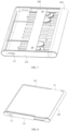
FIG. 1 is a schematic structural diagram of a display device provided by an embodiment of the present disclosure in a state; -
FIG. 2 is a schematic structural diagram of a display device provided by an embodiment of the present disclosure in another state; -
FIG. 3 is an exploded perspective view of a support structural member provided by an embodiment of the present disclosure; -
FIG. 4 is a cross-sectional view of a support structural member provided by an embodiment of the present disclosure; -
FIGS. 5 to 7 are schematic structural diagrams of a support structural member provided in an embodiment of the present disclosure in a retracted state; -
FIGS. 8 to 10 are schematic structural diagrams of a support structural member provided by an embodiment of the present disclosure in a deployed state; -
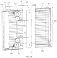
FIG. 11 is a partial perspective exploded view of a support structural member provided by an embodiment of the present disclosure; -
FIG. 12 is a schematic structural diagram ofFIG. 11 from another viewing angle; -
FIG. 13 is a partial enlarged schematic view of Part I inFIG. 12 . - For a better understanding of the present disclosure, a support structural member and a display device of embodiments of the present disclosure will be described in detail below with reference to
FIGS. 1 to 13 . - Please refer to
FIG. 1 and FIG. 2 together. According to an embodiment of the present disclosure, a display device is provided. The display device includes aflexible display panel 10 and a supportstructural member 20. The supportstructural member 20 is used to provide support for theflexible display panel 10. The display device includes a first side AA1 and a second side AA2 disposed opposite to each other in a first direction (Z direction inFIG. 1 ). - The display device in the embodiment of the present disclosure includes but are not limited to a mobile phone, a personal digital assistant (Personal Digital Assistant, PDA for short), a tablet computer, an e-book, a television, access control, a smart fixed phone, a console, and other devices with display functions.
- In some optional embodiments, the
flexible display panel 10 can be bent and the supportstructural member 20 can be retracted, and at least part of theflexible display panel 10 can be bent and extends to the second side AA2 of the supportstructural member 20. When the supportstructural member 20 is deployed, theflexible display panel 10 located on the second side AA2 can move to the first side AA1, thereby increasing the display area of the display device. For example, when the support structural member is changed from the state shown inFIG. 1 to the state shown inFIG. 2 , the size of the display device in the second direction (X direction inFIG. 1 ) increases, the display area of theflexible display panel 10 on the first side AA1 increases, and a displayable area of the display device increases. - Optionally, the
flexible display panel 10 includes afirst end 11 and asecond end 12 opposite to each other, thefirst end 11 is located on the first side AA1, and thesecond end 12 is located on the second side AA2, so that a part of theflexible display panel 10 is located on the first side AA1, and the other part of theflexible display panel 10 is bent and extends to the second side AA2 of the supportstructural member 20. - In order to better show the relative positional relationship between the support
structural member 20 and theflexible display panel 10 when the supportstructural member 20 is used to support theflexible display panel 10, the structure of the supportstructural member 20 is shown inFIG. 3 . - Another embodiment in another aspect of the present disclosure provides the support
structural member 20 for supporting theflexible display panel 10. The supportstructural member 20 includes the mainbody support member 100, thesliding support member 200 movably connected to the mainbody support member 100 along the second direction, and the pushingmember 300 movably connected to the slidingsupport member 200 along the second direction. The mainbody support member 100 includes abearing portion 110 for bearing a part of theflexible display panel 10. The slidingsupport member 200 includes afirst support portion 210 and asecond support portion 220 spaced along the first direction, thefirst support part 210 is used to extend beyond the mainbody support member 100 and support theflexible display panel 10 together with thebearing portion 110. The pushingmember 300 is movably connected to thesecond support portion 220 along the second direction. The pushingmember 300 includes astopper 310, and thestopper 310 protrudes from the support surface of thesecond support portion 220 for supporting theflexible display panel 10, so that thestopper 310 can stop an end of theflexible display panel 10 and push theflexible display panel 10 to move. - In the support
structural member 20 of the embodiment of the present disclosure, thefirst support portion 210 of thesliding support member 200 can support theflexible display panel 10 together with thebearing portion 110 of the mainbody support member 100, so as to increase the display area and realize large-screen display. - In addition, the
stopper 310 of the pushingmember 300 is disposed on thesecond support portion 220 of thesliding support member 200, and thestopper 310 protrudes from the support surface of thesecond support portion 220, so that thestopper 310 can stop an end of theflexible display panel 10. For example, thestopper 310 may stop thesecond end 12 of theflexible display panel 10. Theflexible display panel 10 can be pushed to move by thestopper 310, so that the part of theflexible display panel 10 folded and disposed on the second side AA2 moves to the first side AA1. In the embodiment of the present disclosure, one end of theflexible display panel 10 is pushed to realize the large-screen display, and thestopper 310 acts on one end of theflexible display panel 10 instead of the surface of theflexible display panel 10, which can reduce the force on theflexible display panel 10 and increase the service life of theflexible display panel 10. - Optionally, the support
structural member 20 further includes aguard component 600. Theguard component 600 is disposed on outer surfaces of both the mainbody support member 100 and the slidingsupport member 200, and theguard component 600 is spaced apart from thebody support member 100 and the slidingsupport member 200, so that theflexible display panel 10 can be located between the mainbody support member 100, thesliding support member 200 and theguard component 600. - Optionally, the support
structural member 20 further includes aback cover 700 connected to theguard component 600 and located on the second side AA2. For example, theback cover 700 is provided with components such as a camera. Theback cover 700 is connected to theguard component 600 and encloses a protective cavity is with theguard component 600. Other components of thesupport structure 20 and theflexible display panel 10 are located in the protective cavity. - The
guard component 600 includes afirst guard portion 610 disposed on the mainbody support member 100 and asecond guard portion 620 disposed on the slidingsupport member 200. Avisible window 630 is formed between thefirst guard portion 610 and thesecond guard portion 620. Theflexible display panel 10 can be exposed from thevisible window 630, and a user views the display screen of theflexible display panel 10 from thevisible window 630. During the movement of the slidingsupport member 200 relative to the mainbody support member 100, thesecond guard portion 620 moves with thesliding support member 200. Thesecond guard portion 620 is wrapped around an outer periphery of thetransitional connection portion 230. - As shown in
FIG. 4 , a first limitingmember 231 and a second limitingmember 232 are disposed in thetransition connection portion 230. A gap is formed between the first limitingmember 231 and the second limitingmember 232, and theflexible display panel 10 passes through the gap between the first limitingmember 231 and the second limitingmember 232. - There are various ways to provide the pushing
member 300. For options, please continue to refer toFIG. 3 . The pushingmember 300 includes amain body portion 320. Themain body portion 320 has a bearing surface for bearing theflexible display panel 10, and thestopper 310 is provided on themain body portion 320 and protruding from the bearing surface. - A plurality of
stoppers 310 are distributed at intervals along the third direction (the Y direction inFIG. 3 ) on themain body portion 320, so that thestoppers 310 can stop different parts of thesecond end 12 in the third direction. - In other embodiments, there are more than two
stoppers 310, and the two ormore stoppers 310 are distributed at intervals along the third direction, so that the two ormore stoppers 310 can stop different parts at thesecond end 12 in the third direction. - Optionally, the support
structural member 20 has a retracted state and a deployed state. - Please continue to refer to
FIGS. 5 to 10 , in the retracted state, part of thesecond support portion 220 and the bearingportion 110 are stacked along the first direction, and the size of the supportstructural member 20 in the second direction is smaller. - In the deployed state, a part of the
second support portion 220 protrudes from the mainbody support member 100, and the size of the supportstructural member 20 in the second direction is relatively large. - When the support
structural member 20 is transformed from the retracted state to the deployed state, the slidingsupport member 200 moves in a direction away from the mainbody support member 100, and at least part of thesecond support portion 220 protrudes from the bearingportion 110. In the second direction, the size of the supportstructural member 20 in the retracted state is smaller than its dimension in the deployed state. That is, when the supportstructural member 20 is transformed from the retracted state to the deployed state, the size of the supportstructural member 20 in the second direction will increase. - As shown in
FIG. 10 to FIG. 13 , the supportstructural member 20 provided according to the embodiment of the present disclosure further includes adrive component 400. Thedrive component 400 is used to drive the slidingsupport member 200 to move relative to the mainbody support member 100 and to drive the pushingmember 300 to move relative to thesecond support portion 220. - When the pushing
member 300 pushes thesecond end 12 of theflexible display panel 10 to move, that is, when theflexible display panel 10 is gradually deployed from the folded state, thedrive component 400 also drives the slidingsupport member 200 to move in a direction away from the mainbody support member 100, thereby improving the friction damage to theflexible display panel 10 caused by theflexible display panel 10 driving the slidingsupport member 200 to move, and further improving the service life of theflexible display panel 10. - Optionally, the
flexible display panel 10 is U-shaped in the folded state, thedrive component 400 drives the slidingsupport member 200 to move relative to themain body support 100 at a first speed V1, and thedrive component 400 drives the pushingmember 300 to move relative to thesecond support portion 220 at a second speed V2. The second speed V2 is twice the first speed V1, that is, V1:V2=1:2. - In these optional embodiments, when the sliding
support member 200 protrudes from the mainbody support member 100 along the second direction by a length L, theflexible display panel 10 located on the first side AA1 and the second side AA2 protrude from the mainbody support member 100 by a length L, the moving distance of thesecond end 12 of theflexible display panel 10 on the second side AA2 is 2L. When the ratio of the first speed V1 to the second speed V2 is 1:2, the distance moved by the pushingmember 300 is twice the distance moved by the slidingsupport member 200 in the same time period. Theflexible display panel 10 extends from the mainbody support member 100 at a speed close to the speed at which the slidingsupport member 200 extends from the mainbody support member 100. The distance of theflexible display panel 10 extending beyond the mainbody support member 100 is equal to the moving distance of the slidingsupport member 200. - Optionally, the sliding
support member 200 further includes thetransition connection portion 230 on its side away from the mainbody support member 100, and thefirst support portion 210 and thesecond support portion 220 are connected to each other via thetransition connection portion 230. Theflexible display panel 10 extends to thesecond support portion 220 around thetransitional connection portion 230. - When the support
structural member 20 is transformed from the retracted state to the deployed state, as the speed at which theflexible display panel 10 extends from the mainbody support member 100 is close to the speed at which the slidingsupport member 200 extends from the mainbody support member 100 in the same time period, the distance of theflexible display panel 10 protruding from the mainbody support member 100 is equal to the moving distance of the slidingsupport member 200, the stability of the distance between theflexible display panel 10 and thetransitional connection portion 230 is ensured and the friction damage of thetransitional connection portion 230 to theflexible display panel 10 is improved and the service life of theflexible display panel 10 is increased. - In some other optional embodiments, the
flexible display panel 10 is wavy in the folded state, a part of theflexible display panel 10 is located on the first side AA1, and the other part bypasses the slidingsupport member 200 and is U-shaped or wavy on the second side AA2. The second speed V2 is an integer multiple of the first speed V1. - For example, when the
flexible display panel 10 is in a wavy shape in the folded state, a part of theflexible display panel 10 is located on the first side AA1, and the other part bypasses the slidingsupport member 200 and is U-shaped on the second side AA2. In the folded state, theflexible display panel 10 is in a three-folded state, and theflexible display panel 10 in the folded state includes three layers stacked in the first direction, so the second speed V2 is three times the first speed V1. - In these optional embodiments, when the support
structural member 20 is stretched and retracted, the speed at which theflexible display panel 10 extends from the mainbody support member 100 is close to the speed at which the slidingsupport member 200 extends from the mainbody support member 100, thereby ensuring the stability of the distance between theflexible display panel 10 and thetransition connection portion 230, improving the friction damage to theflexible display panel 10 caused by thetransition connection portion 230, and further improving the service life of theflexible display panel 10 . - The
drive component 400 can be arranged in various manners. For example, thedrive component 400 may be a motor, and the motor drives the pushingmember 300 and thestopper 310 to move. - In other optional embodiments, the
drive component 400 includes afirst driving group 410 and asecond drive group 420. Thefirst drive group 410 includes afirst drive wheel 411 and afirst rack 412 that are engaged with each other. Thefirst rack 412 is connected to thestopper 310 and is extended and formed in the second direction. Thesecond drive group 420 includes asecond drive wheel 421 and asecond rack 422 that are engaged with each other. Thesecond rack 422 is connected to thesecond support portion 220 and is extended and formed in the second direction. Thesecond drive wheel 421 and thefirst drive wheel 411 are engaged with each other. - The
first drive group 410 drives thestopper 310 to move via thefirst drive wheel 411 and thefirst rack 412. Thesecond drive group 420 drives the slidingsupport member 200 to move via thesecond drive wheel 421 and thesecond rack 422. Thefirst drive wheel 411 and thesecond drive wheel 421 are engaged with each other, so that thefirst drive wheel 411 and thesecond drive wheel 421 can be linked together. When thefirst drive wheel 411 pushes thestopper 310 to move via thefirst rack 412, thesecond drive wheel 421 also pushes the slidingsupport member 200 to move via thesecond rack 422. - Optionally, the
second drive wheel 421 includes afirst gear 421a and asecond gear 421b coaxially arranged, thefirst gear 421a and thefirst drive wheel 411 are engaged with each other, and thesecond gear 421b and thesecond rack 422 are engaged with each other. And the radius of thefirst gear 421a is an integer multiple of the radius of thesecond gear 421b. - In these optional embodiments, the
second drive wheel 421 includes thefirst gear 421a and thesecond gear 421b, and thefirst gear 421a and thefirst drive wheel 411 are engaged with each other, so the rotational speeds of thefirst gear 421a and thefirst drive wheel 411 are equal, and the rotational distances of thefirst gear 421a and thefirst drive wheel 411 are equal. Thesecond gear 421b and thesecond rack 422 are engaged with each other, and thesecond gear 421b is used to drive thesecond rack 422 to be engaged with each other. The radius of thefirst gear 421a is an integer multiple of the radius of thesecond gear 421b, so the rotation distance of thefirst gear 421a is an integer multiple of the rotation distance of thesecond gear 421b, and the second speed V2 is an integer multiple of the first speed V1. - Optionally, the ratio of the second speed V2 to the first speed V1 is equal to the ratio of the radius of the first gear to the radius of the second gear.
- As above, in some optional embodiments, when the second speed V2 is twice the first speed V1, that is, V1:V2=1:2, the radius of the
first gear 421a is twice the radius of thesecond gear 421b. The rotational distance of thefirst gear 421a is twice the rotational distance of thesecond gear 421b in the same time period, so that the second speed V2 is twice the first speed V1. - In other optional embodiments, when the second speed V2 is three times the first speed V1, the radius of the
first gear 421a is three times the radius of thesecond gear 421b, and thefirst gear 421a rotates at the same time The distance is three times the rotational distance of thesecond gear 421b, so that the second speed V2 is three times the first speed V1. - The
drive component 400 of the embodiment of the present disclosure has a simple structure and is convenient to be implemented, and the purpose of reducing the weight of the display device can be achieved and the installation can be simplified. - In the support
structural member 20 provided in the embodiment of the present disclosure, there are various ways of driving thefirst drive group 410 and thesecond drive group 420. For example, thefirst drive group 410 is an active drive group. Thefirst drive wheel 411 in thefirst drive group 410 can be driven to rotate by the drive structure, so that thefirst drive wheel 411 drives thefirst rack 412 and thesecond drive wheel 421 to rotate, and thesecond drive wheel 421 drives thesecond rack 422 to rotate. Or, thefirst rack 412 in thefirst driving group 410 is driven to move via the drive structure, thefirst rack 412 drives thefirst drive wheel 411 to rotate, thefirst drive wheel 411 drives thesecond drive wheel 421 to rotate, and thesecond drive wheel 421 drives thesecond rack 422 to move. - In other embodiments, the
second drive group 420 may also be an active drive group. Thesecond drive wheel 421 in thesecond drive group 420 can be driven to rotate by the drive structure, so that thesecond drive wheel 421 drives thesecond rack 422 and thefirst drive wheel 411 to rotate, and thefirst drive wheel 411 drives thefirst rack 412 to rotate. Or, a motor is used to drive thesecond rack 422 in thesecond drive group 420 to move, thesecond rack 422 drives thesecond drive wheel 421 to rotate, thesecond drive wheel 421 drives thefirst drive wheel 411 to rotate, and thefirst drive wheel 411 drives thefirst rack 412 to move. - There are many ways to provide the drive structure. For example, the drive structure is a motor structure. In some embodiments, the drive structure is a winding
drive member 430, so as to drive thefirst drive wheel 411 and/or thesecond drive wheel 421 to rotate via the windingdrive member 430, and move theejector 300 and the slidingsupport member 200 . - For example, the
first drive group 410 is the active drive group, the windingdrive member 430 can drive thefirst drive wheel 411 of thefirst drive group 410 to rotate, so that thefirst drive wheel 411 drives thesecond drive wheel 421 to rotate, and then thefirst rack 412 and thesecond rack 422 move. - In some optional embodiments, the
second drive group 420 is the active drive group, and the windingdrive member 430 can drive thesecond drive wheel 421 of thesecond drive group 420 to rotate, so that thesecond drive wheel 421 drives thefirst drive wheel 411 to rotate, thereby driving thesecond rack 422 and thefirst rack 412 to move. - As shown in
FIG. 12 and FIG. 13 , the embodiment of the present disclosure is described by taking thesecond drive group 420 as the active drive group as an example. The windingdrive member 430 is disposed on thesecond drive wheel 421, the windingdrive member 430 drives thesecond drive wheel 421 to rotate, thesecond drive wheel 421 drives thefirst drive wheel 411 to rotate, thesecond drive wheel 421 also drives thesecond rack 422 moves, and thefirst drive wheel 411 drives thefirst rack 412 to move. - When the
second drive wheel 421 includes thefirst gear 421a and thesecond gear 421b, the windingdrive member 430 may be disposed on any one of thefirst gear 421a and thesecond gear 421b. For example, the windingdrive member 430 may be disposed on the largerfirst gear 421a, and thefirst gear 421a can provide sufficient installation space for the windingdrive member 430. - The
coil drive member 430 is, for example, a coil spring. Thefirst gear 421a includes, for example, an avoidance recess, and the coil spring is wound in thefirst gear 421a. When theflexible display panel 10 is in the folded state and the supportstructural member 20 is in the retracted state, the windingdrive member 430 is in the retracted state. The windingdrive member 430 can apply a winding drive force to thefirst gear 421a, so thefirst gear 421a and thesecond gear 421b rotates synchronously, thesecond gear 421b drives thesecond rack 422 to move, and thesecond rack 422 drives the slidingsupport member 200 to move in a direction away from the mainbody support member 100, and thus the supportstructural member 20 is transformed from the retracted state to the deployed state. At the same time, thefirst gear 421a is engaged with thefirst drive wheel 411, thefirst gear 421a drives thefirst drive wheel 411 to rotate, thefirst drive wheel 411 drives thefirst rack 412, and thefirst rack 412 drives the pushingmember 300 to push theflexible display panel 10 transitions from the folded state to the flattened state. - The number of the
drive components 400 can be changed according to the actual design. One group ofdrive components 400 can be provided, and one group ofdrive components 400 drives the pushingmember 300 and the slidingsupport member 200 to move. - In other embodiments, there are more than two groups of
drive components 400, and the more than two groups ofdrive components 400 are distributed at intervals along the third direction. Different parts of the pushingmember 300 and the slidingsupport member 200 in the third direction are driven by the more than two groups ofdrive components 400. On the one hand, it can ensure the force balance of the pushingmember 300 and the slidingsupport member 200, and on the other hand, eachdrive component 400 can push the pushingmember 300 and the slidingsupport member 200 to move with less force. - For example, the
drive components 400 are divided into two groups, the two groups ofdrive components 400 are distributed at intervals along the third direction, and the two groups ofdrive components 400 are symmetrically distributed with respect to the axis extending in the second direction. Thefirst racks 412 of the two groups ofdrive components 400 are interconnected to enable the two groups ofdrive components 400 to drive the pushingmember 300 and the slidingsupport member 200 to move more synchronously. - In some optional embodiments, the support
structural member 20 further includes alocking component 500, and thelocking component 500 includes a stoppingportion 510 and apressing portion 520. The stopping portion 51 is engaged with thefirst drive wheel 411 and/or thesecond drive wheel 421. Thepressing portion 520 is fixedly connected with the stoppingportion 510 through the connectingrod 530, and the connectingrod 530 is rotatably arranged around arotating shaft 540, so thepressing portion 520 drives the stoppingportion 510 to move and is engaged with or disengaged from thefirst drive wheel 411 and/or thesecond drive wheel 421. - In these optional embodiments, pressing the
pressing portion 520 enables the connectingrod 530 to rotate, and the connectingrod 530 drives the stoppingportion 510 to engage or separate from thefirst drive wheel 411 and/or thesecond drive wheel 421, so as to control the rotation of thefirst drive wheel 411 and/or thesecond drive wheel 421. - For example, when the
second drive group 420 is an active drive group, thesecond drive wheel 421 includes thefirst gear 421a and thesecond gear 421b, a coil spring is arranged in thefirst gear 421a, and the stoppingportion 510 is used to be engaged with thefirst gear 421a. And when the supportstructural member 20 is in the retracted state, the coil spring is in the retracted state, and thestopper 310 and thefirst gear 421a are engaged with each other to prevent thefirst gear 421a from rotating under the force of the coil spring. Thepressing portion 520 is pressed, and thepressing portion 520 drives the connectingrod 530 to rotate around therotating shaft 540, and the connectingrod 530 drives the stoppingportion 510 and thefirst gear 421a to separate from each other. Thefirst gear 421a will not be subjected to the force of thestopper 510, and thefirst gear 421a rotates under the force of the coil spring, which drives the group of thefirst gears 421a to rotate, so thedrive component 400 can drive the pushingmember 300 and the slidingsupport member 200 to move. When thepressing portion 520 is not pressed, thepressing portion 520 is reset, the connectingrod 530 drives thestopper 510 and thefirst gear 421a to be engaged with each other, thefirst gear 421a will not rotate under the force, so the pushingmember 300 and the slidingsupport member 200 stop moving. - The
stopper 510 is, for example, in the shape of a rack, and is provided with two or more sawtooth spaced apart so thestopper 510 can be engaged with thefirst drive wheel 411 and/or thesecond drive wheel 421. - The connecting
rod 530 can have various shapes. The connectingrod 530 can be straight or bent, as long as pressing thepressing portion 520 enables the connectingrod 530 to drive thestopper 510 to be engaged or separated from thefirst gear 421a. - In some optional embodiments, the
locking component 500 further includes anelastic portion 550, one end of theelastic portion 550 is connected to the side of the connectingrod 530 close to the stoppingportion 510, and theelastic portion 550 can be reciprocally deformed, so theelastic portion 550 can drive the stoppingportion 510 to be engaged with thefirst drive wheel 411 and/or thesecond drive wheel 421. Optionally, one end of theelastic portion 550 is connected to the connectingrod 530, and the other end of theelastic portion 550 is fixed to the slidingsupport member 200. - In these optional embodiments, the
elastic portion 550 is connected to the connectingrod 530 and is located on the side of therotating shaft 540 facing thestop portion 510, and theelastic portion 550 can be reciprocally deformed. Under the elastic force of theelastic portion 550, the connectingrod 530 can drive the stoppingportion 510 to be engaged with thefirst drive wheel 411 and/or thesecond drive wheel 421. - For example, when the
second drive group 420 is an active drive group, thesecond drive wheel 421 includes thefirst gear 421a and thesecond gear 421b. When thepressing portion 520 is not pressed, the connectingrod 530 rebounds under the force of theelastic portion 550, and the connectingrod 530 drives the stoppingportion 510 to be engaged with thefirst gear 421a again. - Optionally, the
pressing portion 520 is disposed protruding from the mainbody support member 100. It is convenient for the user to control the movement of the pushingmember 300 and the slidingsupport member 200 from the outside of the mainbody support member 100 via thepressing portion 520. - Referring to
FIGS. 3 to 10 , for example, the mainbody support member 100 further includesside plates 120 connected to both sides of the bearingportion 110 in the third direction of the supportstructural member 20. Each of theside plates 120 is provided with anavoidance hole 121. Thepressing portion 520 protrudes from theavoidance hole 121. Optionally, theavoidance hole 121 is located at the end of theside plate 120 away from the slidingsupport member 200 and close to the end of themain body support 100. This arrangement conforms an ergonomic design, is convenient for users to operate thepressing portion 520. - Optionally, the main
body support member 100 further includes back plates spaced from the bearingportion 110 along the first direction, and theside plates 120 are connected between the bearingportion 110 and the back plates. Thesecond support portion 220 of the slidingsupport member 200 is disposed on the back plate and is movably disposed along the second direction relative to the back plate. - Referring to
FIGS. 6 ,9 and11 , thefirst support portion 210 includes two or more first support beams 211 spaced along the third direction. The bearingportion 110 includes afirst bearing portion 110a and asecond bearing portion 110b that are sequentially distributed along the second direction. Thesecond bearing portion 110b is located on the side of thefirst bearing portion 110a facing thetransition connection portion 230, and thesecond bearing portion 110b includes two or more second support beams 111 spaced apart in the third direction. The second support beams 111 and the first support beams 211 are alternately distributed along the third direction, so thefirst support portion 210 and the bearingportion 110 can support theflexible display panel 10 on the same plane, to ensure the flatness of the surface for supporting theflexible display panel 10, reduce friction on theflexible display panel 10, and further improve the service life of theflexible display panel 10. Thesecond support beam 111 is provided with a fixing column for fixing the other end of theelastic portion 550.
Claims (20)
- A support structural member for a flexible display panel, comprising:a main body support member, comprising a bearing portion for bearing a part of the flexible display panel;a sliding support member, movably connected to the main body support member along a second direction, wherein the sliding support member comprises a first support portion and a second support portion spaced along a first direction, and the first support portion extends beyond the main body support member and supports the flexible display panel together with the bearing portion;a pushing member, movably connected to the second support portion along the second direction, wherein the pushing member comprises a stopper, and the stopper protrudes from a support surface of the second support portion for supporting the flexible display panel, so the stopper stops an end of the flexible display panel and pushes the flexible display panel to move.
- The support structural member according to claim 1, further comprising: a drive component for driving the sliding support member to move relative to the main body support member at a first speed V1 and for driving the pushing member to move relative to the second support portion at a second speed V2, wherein the second speed V2 is an integer multiple of the first speed V1.
- The support structural member according to claim 2, wherein the second speed V2 is twice the first speed V1.
- The support structural member according to claim 2, wherein the drive component comprises:a first drive group, comprising a first drive wheel and a first rack that are engaged with each other, wherein the first rack is connected to the stopper and extends along the second direction;a second drive group, comprising a second drive wheel and a second rack that are engaged with each other, wherein the second rack is connected to the second support portion and extends along the second direction, and the second drive wheel is engaged with the first drive wheel.
- The support structural member according to claim 4, wherein the second drive wheel comprises a first gear and a second gear coaxially arranged, the first gear is engaged with the first drive wheel, the second gear is engaged with the second rack, and a radius of the first gear is an integral multiple of that of the second gear.
- The support structural member according to claim 5, wherein the ratio of the second speed V2 to the first speed V1 is equal to the ratio of the radius of the first gear to that of the second gear.
- The support structural member according to claim 5, wherein the radius of the first gear is twice the radius of the second gear.
- The support structural member according to claim 3, wherein at least one of the first drive wheel and the second drive wheel is provided with a winding drive to drive the first drive wheel and/or the second drive wheel to rotate by the winding drive and drive the sliding support member to extend beyond the main body support member.
- The support structural member according to claim 8, wherein the winding drive is a coil spring.
- The support structural member according to claim 8, further comprising: a locking component comprising:a stopping portion for engaging with the first drive wheel and/or the second drive wheel;a pressing portion fixedly connected with the stopping portion through a connecting rod, wherein the connecting rod is rotatably arranged around a rotating shaft, so the pressing portion drives the stopping portion to move and is engaged with or disengaged from the first drive wheel and/or the second drive wheel.
- The support structural member according to claim 10, wherein the pressing portion is protruded from the main body support member.
- The support structural member according to claim 10, wherein the locking component further comprises an elastic portion connected to a side of the connecting rod close to the stopping portion, and the elastic portion can be reciprocatingly deformed, so the elastic portion can drive the stopping portion to engage with the first drive wheel and/or the second drive wheel.
- The support structural member according to claim 4, wherein there are more than two groups of drive components, and the two or more groups of drive components are spaced apart along a third direction, and the third direction intersects the first direction and the second direction.
- The support structural member according to claim 13, wherein the two or more groups of drive components are symmetrically distributed along the third direction, and the first racks of the two or more groups of drive components are connected to each other.
- The support structural member according to claim 1, wherein the pushing member further comprises a main body portion with a bearing surface for bearing the flexible display panel, and the stopper is disposed on the main body portion and protrude from the bearing surface.
- The support structural member according to claim 15, wherein the number of the stopper is two or more, and the two or more stoppers are distributed on the main body portion at intervals along the third direction.
- The support structural member according to claim 1, wherein:the sliding support member further comprises a transition connection portion on a side thereof away from the main body support member, the first support portion and the second support portion are connected to each other by the transition connection portion, and the first support portion comprises two or more first support beams spaced along the third direction;the bearing portion comprises a first bearing portion and a second bearing portion distributed in sequence along the first direction, the second bearing portion is located on a side of the first bearing portion toward the transition connection portion, the second bearing portion comprises two or more second support beams spaced along the third direction, and the second support beams and the first support beams are alternately distributed along the third direction.
- The support structural member according to claim 1, further comprising: a guard component disposed on outer surfaces of the main body support member and the sliding support member, the guard component is arranged to be spaced apart from the main body support member and the sliding support member, so the flexible display panel is located between the main body support member, the sliding support member and the guard component.
- The support structural member according to claim 18, wherein the guard component comprises a first guard portion provided on the main body support member and a second guard portion provided on the sliding support member, the first guard portion and the second guard portion encloses to form a visible window, so the flexible display panel can be exposed from the visible window.
- A display device, comprising:the support structural member of any one of claims 1-19;a flexible display panel, comprising a first end and a second end opposite to each other, wherein the first end is connected to the main body support member, the second end is located on the second support portion and is stopped by the stopper, so the stopper can push the second end to move in a direction away from the main body support member.
Applications Claiming Priority (2)
| Application Number | Priority Date | Filing Date | Title |
|---|---|---|---|
| CN202110112033.5A CN112797277B (en) | 2021-01-27 | 2021-01-27 | Support structure and display device |
| PCT/CN2021/126613 WO2022160815A1 (en) | 2021-01-27 | 2021-10-27 | Support structural members and display apparatus |
Publications (2)
| Publication Number | Publication Date |
|---|---|
| EP4224053A1 true EP4224053A1 (en) | 2023-08-09 |
| EP4224053A4 EP4224053A4 (en) | 2024-05-01 |
Family
ID=75812202
Family Applications (1)
| Application Number | Title | Priority Date | Filing Date |
|---|---|---|---|
| EP21922406.0A Pending EP4224053A4 (en) | 2021-01-27 | 2021-10-27 | Support structural members and display apparatus |
Country Status (6)
| Country | Link |
|---|---|
| US (1) | US12222756B2 (en) |
| EP (1) | EP4224053A4 (en) |
| JP (1) | JP7550979B2 (en) |
| KR (1) | KR102863207B1 (en) |
| CN (1) | CN112797277B (en) |
| WO (1) | WO2022160815A1 (en) |
Families Citing this family (11)
| Publication number | Priority date | Publication date | Assignee | Title |
|---|---|---|---|---|
| CN112797277B (en) * | 2021-01-27 | 2022-11-11 | 昆山国显光电有限公司 | Support structure and display device |
| CN113063075B (en) | 2021-04-09 | 2023-03-28 | 昆山工研院新型平板显示技术中心有限公司 | Supporting structural part and display device |
| CN113242342B (en) * | 2021-06-17 | 2023-07-18 | Oppo广东移动通信有限公司 | Locking mechanism and electronic equipment |
| CN113593411B (en) * | 2021-07-30 | 2023-08-29 | 京东方科技集团股份有限公司 | display device |
| CN114220350B (en) * | 2021-12-28 | 2024-04-26 | 昆山国显光电有限公司 | Support structure and display device |
| WO2023182619A1 (en) * | 2022-03-25 | 2023-09-28 | 삼성전자 주식회사 | Electronic apparatus comprising driver for driving housing |
| CN115148098B (en) * | 2022-04-14 | 2023-11-28 | 昆山国显光电有限公司 | Support structure, working method of support structure and display device |
| CN115654268B (en) * | 2022-05-10 | 2025-08-08 | 昆山国显光电有限公司 | Support assembly and display device |
| KR20240010607A (en) * | 2022-07-14 | 2024-01-24 | 삼성디스플레이 주식회사 | Display device and manufacturing method thereof |
| CN115148137B (en) * | 2022-07-25 | 2026-03-20 | 京东方科技集团股份有限公司 | Display device and display panel movement control method, device, medium, equipment |
| KR20240042315A (en) * | 2022-09-23 | 2024-04-02 | 삼성디스플레이 주식회사 | Display device |
Family Cites Families (26)
| Publication number | Priority date | Publication date | Assignee | Title |
|---|---|---|---|---|
| US6057607A (en) | 1999-07-16 | 2000-05-02 | Semtech Corporation | Method and apparatus for voltage regulation in multi-output switched mode power supplies |
| US6988695B2 (en) * | 2002-09-04 | 2006-01-24 | Jeff Burris | Adjustable and collapsible display stand |
| US6857607B1 (en) * | 2002-09-04 | 2005-02-22 | Collapsible display stand | |
| KR101107127B1 (en) * | 2010-01-12 | 2012-01-31 | 주식회사 다이아벨 | Mobile terminal |
| US9286812B2 (en) * | 2011-06-07 | 2016-03-15 | Microsoft Technology Licensing, Llc | Flexible display extendable assembly |
| KR101848891B1 (en) * | 2016-01-04 | 2018-04-16 | 신진철 | Display expansion type mobile terminal with sliding motion |
| KR102691770B1 (en) * | 2016-09-20 | 2024-08-05 | 삼성디스플레이 주식회사 | Flexible display device |
| CN108664087A (en) * | 2018-07-23 | 2018-10-16 | Oppo广东移动通信有限公司 | Portable electronic device and its flexible display apparatus |
| KR102477229B1 (en) * | 2018-07-30 | 2022-12-13 | 삼성디스플레이 주식회사 | Display device and moving method thereof |
| CN109658825B (en) | 2018-10-29 | 2021-04-16 | 努比亚技术有限公司 | Connecting piece, coupling assembling, bending apparatus and flexible screen terminal |
| CN209515060U (en) | 2019-01-26 | 2019-10-18 | 东莞市劲丰电子有限公司 | Drawing and pulling type companding mechanism based on flexible screen application |
| CN110047387B (en) * | 2019-05-06 | 2024-02-09 | 武汉华星光电半导体显示技术有限公司 | Organic light emitting diode display device |
| CN112153181B (en) * | 2019-06-27 | 2022-06-14 | 华为机器有限公司 | A flexible display telescopic mechanism and mobile terminal |
| CN112153180B (en) * | 2019-06-27 | 2023-04-11 | 华为机器有限公司 | Display screen telescopic machanism and mobile terminal |
| CN110491289B (en) * | 2019-07-29 | 2024-03-15 | 武汉华星光电半导体显示技术有限公司 | Display device |
| CN110599912A (en) * | 2019-10-15 | 2019-12-20 | Oppo广东移动通信有限公司 | Electronic device |
| CN111243440B (en) * | 2020-03-11 | 2022-05-17 | 昆山国显光电有限公司 | Flexible display device |
| CN111510536B (en) * | 2020-05-26 | 2025-04-25 | 武汉华星光电半导体显示技术有限公司 | Display device |
| CN111508374A (en) * | 2020-05-26 | 2020-08-07 | 武汉华星光电半导体显示技术有限公司 | Flexible display device |
| US11314285B2 (en) * | 2020-05-26 | 2022-04-26 | Wuhan China Star Optoelectronics Semiconductor Display Technology Co., Ltd. | Flexible display device with stretching members and transmission mechanism |
| CN111508373B (en) * | 2020-05-26 | 2024-09-24 | 武汉华星光电半导体显示技术有限公司 | Flexible display device |
| US12019479B2 (en) * | 2020-06-30 | 2024-06-25 | Wuhan China Star Optoelectronics Semiconductor Display Technology Co., Ltd. | Flexible display device |
| CN111768709B (en) * | 2020-07-15 | 2023-08-01 | 京东方科技集团股份有限公司 | A display device and electronic device |
| US12418602B2 (en) * | 2020-09-14 | 2025-09-16 | Lg Electronics Inc. | Mobile terminal |
| CN112133203B (en) * | 2020-10-16 | 2022-05-20 | 昆山国显光电有限公司 | Supporting device and display device |
| CN112797277B (en) * | 2021-01-27 | 2022-11-11 | 昆山国显光电有限公司 | Support structure and display device |
-
2021
- 2021-01-27 CN CN202110112033.5A patent/CN112797277B/en active Active
- 2021-10-27 JP JP2023526631A patent/JP7550979B2/en active Active
- 2021-10-27 WO PCT/CN2021/126613 patent/WO2022160815A1/en not_active Ceased
- 2021-10-27 KR KR1020237014653A patent/KR102863207B1/en active Active
- 2021-10-27 EP EP21922406.0A patent/EP4224053A4/en active Pending
-
2023
- 2023-03-27 US US18/190,480 patent/US12222756B2/en active Active
Also Published As
| Publication number | Publication date |
|---|---|
| US12222756B2 (en) | 2025-02-11 |
| WO2022160815A1 (en) | 2022-08-04 |
| CN112797277A (en) | 2021-05-14 |
| KR20230067698A (en) | 2023-05-16 |
| JP2023549725A (en) | 2023-11-29 |
| US20230229191A1 (en) | 2023-07-20 |
| JP7550979B2 (en) | 2024-09-13 |
| KR102863207B1 (en) | 2025-09-23 |
| CN112797277B (en) | 2022-11-11 |
| EP4224053A4 (en) | 2024-05-01 |
Similar Documents
| Publication | Publication Date | Title |
|---|---|---|
| US12222756B2 (en) | Support structural member and display device | |
| EP3842894B1 (en) | Hinge structure and folding electronic device | |
| EP4362435A1 (en) | Electronic device | |
| US12204377B2 (en) | Flexible display device | |
| CN111343310B (en) | Display device and mobile terminal | |
| EP4009136B1 (en) | Electronic device with flexible display | |
| US12591277B2 (en) | Hinge device of portable terminal with foldable structure | |
| CN112751961B (en) | Folding mechanism and electronic equipment | |
| EP4138371A1 (en) | Rotating mechanism, support device, and folding screen terminal | |
| JP7466770B2 (en) | Electronics | |
| CN113129758A (en) | Display device | |
| CN116696929B (en) | Damping mechanism, folding hinge and electronic equipment | |
| EP4485908A1 (en) | Rotating shaft mechanism and foldable device | |
| EP4484773A1 (en) | Rotating shaft apparatus, folding housing and electronic device | |
| CN114283697B (en) | Folding device and display equipment | |
| CN114220350B (en) | Support structure and display device | |
| US12610004B2 (en) | Electronic device with slidable flexible display screen | |
| JP7709613B2 (en) | Rotating shaft mechanism and electronic device | |
| EP4496299A1 (en) | Rotating shaft apparatus and foldable-screen device | |
| US11800662B2 (en) | Deformable display device and deformation control method therefor | |
| CN113539089B (en) | Display device and mobile terminal | |
| CN113176812B (en) | Electronic equipment | |
| EP4561033A1 (en) | Electronic apparatus and folding assembly | |
| CN111263048A (en) | Transmission components, camera modules and electronic equipment | |
| CN114170910B (en) | Folding display device |
Legal Events
| Date | Code | Title | Description |
|---|---|---|---|
| STAA | Information on the status of an ep patent application or granted ep patent |
Free format text: STATUS: THE INTERNATIONAL PUBLICATION HAS BEEN MADE |
|
| PUAI | Public reference made under article 153(3) epc to a published international application that has entered the european phase |
Free format text: ORIGINAL CODE: 0009012 |
|
| STAA | Information on the status of an ep patent application or granted ep patent |
Free format text: STATUS: REQUEST FOR EXAMINATION WAS MADE |
|
| 17P | Request for examination filed |
Effective date: 20230502 |
|
| AK | Designated contracting states |
Kind code of ref document: A1 Designated state(s): AL AT BE BG CH CY CZ DE DK EE ES FI FR GB GR HR HU IE IS IT LI LT LU LV MC MK MT NL NO PL PT RO RS SE SI SK SM TR |
|
| A4 | Supplementary search report drawn up and despatched |
Effective date: 20240403 |
|
| DAV | Request for validation of the european patent (deleted) | ||
| DAX | Request for extension of the european patent (deleted) | ||
| RIC1 | Information provided on ipc code assigned before grant |
Ipc: F16M 13/00 20060101ALI20240326BHEP Ipc: F16M 11/18 20060101ALI20240326BHEP Ipc: F16M 11/04 20060101AFI20240326BHEP |
|
| STAA | Information on the status of an ep patent application or granted ep patent |
Free format text: STATUS: EXAMINATION IS IN PROGRESS |
|
| 17Q | First examination report despatched |
Effective date: 20251217 |