EP4223969B1 - A folding movable panels system - Google Patents
A folding movable panels system Download PDFInfo
- Publication number
- EP4223969B1 EP4223969B1 EP22210230.3A EP22210230A EP4223969B1 EP 4223969 B1 EP4223969 B1 EP 4223969B1 EP 22210230 A EP22210230 A EP 22210230A EP 4223969 B1 EP4223969 B1 EP 4223969B1
- Authority
- EP
- European Patent Office
- Prior art keywords
- engaged
- head
- pin
- panel
- sliding
- Prior art date
- Legal status (The legal status is an assumption and is not a legal conclusion. Google has not performed a legal analysis and makes no representation as to the accuracy of the status listed.)
- Active
Links
Images

Classifications
-
- E—FIXED CONSTRUCTIONS
- E05—LOCKS; KEYS; WINDOW OR DOOR FITTINGS; SAFES
- E05D—HINGES OR SUSPENSION DEVICES FOR DOORS, WINDOWS OR WINGS
- E05D15/00—Suspension arrangements for wings
- E05D15/26—Suspension arrangements for wings for folding wings
- E05D15/264—Suspension arrangements for wings for folding wings for bi-fold wings
- E05D15/266—Suspension arrangements for wings for folding wings for bi-fold wings comprising two pivots placed at opposite edges of the wing
-
- E—FIXED CONSTRUCTIONS
- E05—LOCKS; KEYS; WINDOW OR DOOR FITTINGS; SAFES
- E05Y—INDEXING SCHEME ASSOCIATED WITH SUBCLASSES E05D AND E05F, RELATING TO CONSTRUCTION ELEMENTS, ELECTRIC CONTROL, POWER SUPPLY, POWER SIGNAL OR TRANSMISSION, USER INTERFACES, MOUNTING OR COUPLING, DETAILS, ACCESSORIES, AUXILIARY OPERATIONS NOT OTHERWISE PROVIDED FOR, APPLICATION THEREOF
- E05Y2201/00—Constructional elements; Accessories therefor
- E05Y2201/60—Suspension or transmission members; Accessories therefor
- E05Y2201/622—Suspension or transmission members elements
- E05Y2201/628—Bearings
-
- E—FIXED CONSTRUCTIONS
- E05—LOCKS; KEYS; WINDOW OR DOOR FITTINGS; SAFES
- E05Y—INDEXING SCHEME ASSOCIATED WITH SUBCLASSES E05D AND E05F, RELATING TO CONSTRUCTION ELEMENTS, ELECTRIC CONTROL, POWER SUPPLY, POWER SIGNAL OR TRANSMISSION, USER INTERFACES, MOUNTING OR COUPLING, DETAILS, ACCESSORIES, AUXILIARY OPERATIONS NOT OTHERWISE PROVIDED FOR, APPLICATION THEREOF
- E05Y2201/00—Constructional elements; Accessories therefor
- E05Y2201/60—Suspension or transmission members; Accessories therefor
- E05Y2201/622—Suspension or transmission members elements
- E05Y2201/64—Carriers
-
- E—FIXED CONSTRUCTIONS
- E05—LOCKS; KEYS; WINDOW OR DOOR FITTINGS; SAFES
- E05Y—INDEXING SCHEME ASSOCIATED WITH SUBCLASSES E05D AND E05F, RELATING TO CONSTRUCTION ELEMENTS, ELECTRIC CONTROL, POWER SUPPLY, POWER SIGNAL OR TRANSMISSION, USER INTERFACES, MOUNTING OR COUPLING, DETAILS, ACCESSORIES, AUXILIARY OPERATIONS NOT OTHERWISE PROVIDED FOR, APPLICATION THEREOF
- E05Y2201/00—Constructional elements; Accessories therefor
- E05Y2201/60—Suspension or transmission members; Accessories therefor
- E05Y2201/622—Suspension or transmission members elements
- E05Y2201/688—Rollers
-
- E—FIXED CONSTRUCTIONS
- E05—LOCKS; KEYS; WINDOW OR DOOR FITTINGS; SAFES
- E05Y—INDEXING SCHEME ASSOCIATED WITH SUBCLASSES E05D AND E05F, RELATING TO CONSTRUCTION ELEMENTS, ELECTRIC CONTROL, POWER SUPPLY, POWER SIGNAL OR TRANSMISSION, USER INTERFACES, MOUNTING OR COUPLING, DETAILS, ACCESSORIES, AUXILIARY OPERATIONS NOT OTHERWISE PROVIDED FOR, APPLICATION THEREOF
- E05Y2900/00—Application of doors, windows, wings or fittings thereof
- E05Y2900/10—Application of doors, windows, wings or fittings thereof for buildings or parts thereof
- E05Y2900/13—Type of wing
- E05Y2900/132—Doors
-
- E—FIXED CONSTRUCTIONS
- E05—LOCKS; KEYS; WINDOW OR DOOR FITTINGS; SAFES
- E05Y—INDEXING SCHEME ASSOCIATED WITH SUBCLASSES E05D AND E05F, RELATING TO CONSTRUCTION ELEMENTS, ELECTRIC CONTROL, POWER SUPPLY, POWER SIGNAL OR TRANSMISSION, USER INTERFACES, MOUNTING OR COUPLING, DETAILS, ACCESSORIES, AUXILIARY OPERATIONS NOT OTHERWISE PROVIDED FOR, APPLICATION THEREOF
- E05Y2900/00—Application of doors, windows, wings or fittings thereof
- E05Y2900/10—Application of doors, windows, wings or fittings thereof for buildings or parts thereof
- E05Y2900/13—Type of wing
- E05Y2900/148—Windows
- E05Y2900/15—Balcony glazing
Definitions
- the panels are typically made of glass and are large in size, allowing for natural lighting of an environment, even with panels in the closed position.
- movable panels systems wherein said panels are engaged to an upper guide which is in turn attached to a ceiling or a beam whereupon, therefore, the full force of the weight of the panels is entirely born. Examples of these known movable panels systems are disclosed in documents DE19854739C1 and US2007/272372A1 .
- the characteristics of the building or the load-bearing structure do not permit the installation of known movable panels systems.
- the object of the present invention is to present a movable panels system that meets the aforementioned needs and overcomes the aforementioned disadvantages.
- the folding movable panels system is indicated in the entirety thereof with the number 1.
- the movable panels system 1 comprises a longitudinal axis X-X, for example parallel to a ground plane P, and a vertical axis V-V.
- the movable panels system 1 comprises a lower guide 2 resting on the ground plane P and a vertically spaced upper guide 3.
- the lower guide 2 and the upper guide 3 are implemented at least partially by means of extrusion, for example from metal.
- the lower guide 2 comprises at least one rail 20 extending along the longitudinal axis X-X.
- the rail 20 has a T-shaped cross-section, comprising a protruding rail head 25.
- the lower guide 2 comprises at least one pair of rails 20 spaced apart transversely.
- the lower guide 2 comprises two auxiliary partitions 27, spaced apart transversely, which extend along the longitudinal axis X-X and define an auxiliary housing 270, which is described in greater detail hereinafter.
- the auxiliary partitions 27 have an inverted L-shaped cross-section.
- auxiliary partitions 27 are transversely comprised between two rails 20 of the lower guide 2.
- the movable panels system 1 comprises a plurality of movable panels 4a, 4b of a planar shape, preferably made of glass, mutually hinged, and each comprising a lower edge 42a, 42b and an upper edge 43a, 43b.
- the movable panels system 1 comprises at least one connecting hinge device, preferably two vertically spaced connecting hinge devices.
- the connecting hinge device is engaged with each pair of adjacent panels, preferably with respective side edges of the two adjacent panels.
- the desired "book” or “bellows” effect of the movable sliding panels is obtained by means of the connection hinge device.
- the movable panels system 1 comprises at least one sliding panel 4a movable along the longitudinal axis X-X.
- the sliding panel 4a engages in a sliding manner on a relevant rail 20.
- the movable panels system 1 comprises a plurality of sliding panels 4a mutually hinged and sliding on a relevant rail 20 along the longitudinal axis X-X.
- the movable panels system 1 comprises rotation and sliding means operatively connected to the sliding panel 4a, suitable for allowing the rotation and sliding of said sliding panel 4a.
- the rotation and sliding means comprise a load-bearing carriage group 5 and a hinge device 6.
- the hinge device 6 is engaged to the upper edge 43a of the sliding panel 4a and is housed in a rotationally and freely sliding manner at least partially in the upper guide 3.
- the load-bearing carriage group 5 is engaged to the lower edge 42a and comprises a supporting body 50 and a plurality of wheels 53.
- each wheel 53 is engaged in a slidingly free manner to the at least one rail 20 and hinged in a rotationally free manner to the supporting body 50 in a wheel axis W-W substantially parallel to the ground plane P, for example substantially horizontal.
- the load-bearing carriage 5 comprises at least two wheels 53 positioned on opposite sides.
- the load-bearing carriage group 5 comprises at least two pairs of wheels 53, each pair being positioned on one side, wherein the wheels 53 of each pair are longitudinally aligned.
- the load-bearing carriage group 5 comprises at least one auxiliary wheel 54 hinged to the supporting body 50 in a substantially vertical auxiliary axis Q-Q.
- the load-bearing carriage group 5 comprises at least two auxiliary wheels 54 positioned on opposite sides.
- the auxiliary wheel 54 engages the lower guide 2 in such a way as to prevent detachment in the vertical direction, i.e., to prevent lifting of the panels 4a, 4b.
- the load-bearing carriage group 5 further comprises a lower pin 51 extending along a substantially vertical first rotation axis R1-R1, engaged to the supporting body 50.
- the load-bearing carriage group 5 comprises a lower body 52 engaged to the sliding panel 4a and to the lower edge 42a, and engaged in a rotationally free manner to the supporting body 50 by means of the lower pin 51.
- the load-bearing carriage group 5 comprises a thrust bearing 55, suitable for receiving forces acting along the first rotation axis R1-R1, engaged to the lower pin 51 and engaged to the supporting body 50 or to the lower body 52, suitable for allowing the rotation of the lower body 52 in relation to the supporting body 50.
- the base body 80 comprises an upper base portion, wherefrom the lower head pin 84 protrudes, and a lower base portion 806, facing the lower guide 2.
- the lower body 52, the upper body 62, the upper head body 72 and the lower head body 82 have substantially the same characteristics as those described above.
- Said components are substantially identical parts, except for the fact that they are used in different positions and for different purposes, for example operating on a movable panel and/or head panel.
- the movable panels system 1 comprises a box-like body 9 for at least one edge 42a, 42b of the at least one sliding panel 4a and/or for at least one edge 43a, 43b of the head panel 4b.
- the upper body 62 is integrally connected at the box-like body 9.
- the upper head body 72 is integrally connected to a box-like body 9.
- the lower head body 82 is integrally connected to a box-like body 9.
- the flexible covering member 10 extends substantially along the entire longitudinal length of the box-like body 9.
- the flexible covering member 10 extends at least partially overlapping a relevant rail 2, 3.
- the at least one flexible covering member 10 elastically deforms in contact with said guide 2, 3.
- the flexible covering member 10 at least partially covers the rotation and sliding means of the sliding panel 4a.
- the flexible covering member 10 at least partially covers the rotation means of the head panel 4b.
- the folding movable panels system fully fulfills the intended object in overcoming the typical problems of the prior art.
- the upper rail does not have a panel support function, i.e. it does not support any weight.
- the upper guide is structurally simple and inexpensive to implement.
- the vertical alignment of the panels is ensured, especially during rotation.
- the vertical load balancing is ensured.
- the auxiliary wheels prevent vertical misalignments and favor homogeneous sliding.
- the movable panels systems has panels that are prevented from undesired lifting and detaching from the lower guide thereby reducing the risk of injury.
- the auxiliary wheels engage to the lower guide in an anti-lifting manner.
- the anti-lifting profile of the base body has an anti-lifting function.
- the assembly of the movable panels system is simple, as it comprises a limited number of components.
- the movable panels system has strong aesthetic qualities.
- the at least one flexible covering member covers a relevant guide, hiding from view the means of rotation and/or the means of rotation and sliding.
- the problem of the accumulation of dirt and water within the guides is avoided, presenting a clean aesthetic and obviating the need for frequent maintenance and cleaning operations.
Landscapes
- Engineering & Computer Science (AREA)
- Mechanical Engineering (AREA)
- Extensible Doors And Revolving Doors (AREA)
Description
- The present invention relates to a folding movable panels system.
- In the prior art, there are known solutions for movable panels systems that, according to requirements, make it possible to close off an environment, for example a veranda.
- In particular, a movable panels system is configurable in a closing configuration, in which the panels are arranged longitudinally and separate the two adjacent environments, and a packaged configuration, in which the panels are rotated and mutually adjacent in such a way as to connect the two environments.
- In the prior art, there are solutions for movable panels systems known as "folding door" or "bi-folding door" systems. Specifically, there are different types of movable panels systems, for example "bi-folding door with access door", "hybrid sliding and bi-folding" and "sliding center folding" systems.
- In the known embodiments, the panels are typically made of glass and are large in size, allowing for natural lighting of an environment, even with panels in the closed position.
- within the sector, movable panels systems are known wherein said panels are engaged to an upper guide which is in turn attached to a ceiling or a beam whereupon, therefore, the full force of the weight of the panels is entirely born. Examples of these known movable panels systems are disclosed in documents
DE19854739C1 andUS2007/272372A1 . - The main problem with the known solutions is in relation to the dimensions of the panels which in the technical sector are required to be increasingly more significant.
- Firstly, as the dimensions increase, the support and movement of the panels becomes a critical factor in the design and life of associated systems.
- Secondly, in some cases or for some types of installations, for example for outdoor use, the characteristics of the building or the load-bearing structure do not permit the installation of known movable panels systems.
- In addition, in some known solutions, the presence of panels of significant dimensions has been the cause of structural problems in relation to the upper beams whereupon they bear.
- The object of the present invention is to present a movable panels system that meets the aforementioned needs and overcomes the aforementioned disadvantages.
- This object is achieved by the movable panels system claimed in
claim 1. The claims dependent on these request protection for further features and entail further technical benefits. - In addition, further features and advantages of the invention will become clear from the description provided below of the preferred embodiments thereof given as non-limiting examples in reference to the attached figures, wherein:
-
Figures 1, 1a and 1b show a perspective view of the movable panels system in accordance with the present invention, according to a preferred embodiment, respectively in the closing configuration, in an intermediate configuration and in a packaged configuration; -
Figure 2 depicts a perspective view of separate parts of the movable panels system in accordance with the present invention, according to a preferred embodiment; -
Figure 2a shows a lateral view of the movable panels systems in accordance with the present invention, according to a preferred embodiment; -
Figure 3 shows a cross-sectional view of the movable panels system ofFigure 2a , along the section plane A-A, according to a preferred embodiment; -
Figures 3a and 3b show an enlarged detail ofFigure 3 , respectively within a region proximal to the upper guide and the lower guide; -
Figure 4 shows a cross-sectional view of the movable panels system ofFigure 2a , along the sectional plane B-B, according to a preferred embodiment; -
Figures 4a and 4b show an enlarged detail ofFigure 4 , respectively within a region proximal to the upper guide and to the lower guide; -
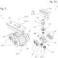
Figures 5 and 5a show a load-bearing carriage group of the movable panels system according to the present invention, according to a preferred embodiment, respectively mounted and in separate parts; -
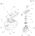
Figures 6 and 6a show a hinge device of the movable panels system according to the present invention, according to a preferred embodiment, respectively mounted and in separate parts; -
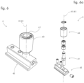
Figures 7 and 7a show a head bearing group of the movable panels system according to the present invention, according to a preferred embodiment, respectively mounted and in separate parts; -
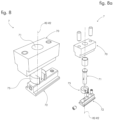
Figures 8 and 8a show a head hinge device of the movable panels system according to the present invention, according to a preferred embodiment, respectively mounted and in separate. - With reference to the attached figures, the folding movable panels system is indicated in the entirety thereof with the
number 1. - According to the present invention, the
movable panels system 1 comprises a longitudinal axis X-X, for example parallel to a ground plane P, and a vertical axis V-V. - According to the present invention, the
movable panels system 1 comprises alower guide 2 resting on the ground plane P and a vertically spacedupper guide 3. - According to a preferred embodiment, the
lower guide 2 and theupper guide 3 are implemented at least partially by means of extrusion, for example from metal. - According to the present invention, the
lower guide 2 comprises at least one rail 20 extending along the longitudinal axis X-X. - According to a preferred embodiment, the rail 20 has a T-shaped cross-section, comprising a protruding rail head 25.
- According to a preferred embodiment, the
lower guide 2 comprises at least one pair of rails 20 spaced apart transversely. - The
lower guide 2 comprises twoauxiliary partitions 27, spaced apart transversely, which extend along the longitudinal axis X-X and define anauxiliary housing 270, which is described in greater detail hereinafter. - The
auxiliary partitions 27 have an inverted L-shaped cross-section. - According to a preferred embodiment, the
auxiliary partitions 27 are transversely comprised between two rails 20 of thelower guide 2. - According to the present invention, the
movable panels system 1 comprises a plurality ofmovable panels lower edge upper edge - According to a preferred embodiment, the
movable panels system 1 comprises at least one connecting hinge device, preferably two vertically spaced connecting hinge devices. The connecting hinge device is engaged with each pair of adjacent panels, preferably with respective side edges of the two adjacent panels. The desired "book" or "bellows" effect of the movable sliding panels is obtained by means of the connection hinge device. - In particular, the
movable panels system 1 comprises at least onesliding panel 4a movable along the longitudinal axis X-X. - Preferably, the
sliding panel 4a engages in a sliding manner on a relevant rail 20. - According to a preferred embodiment, the
movable panels system 1 comprises a plurality ofsliding panels 4a mutually hinged and sliding on a relevant rail 20 along the longitudinal axis X-X. - According to the present invention, the
movable panels system 1 comprises rotation and sliding means operatively connected to thesliding panel 4a, suitable for allowing the rotation and sliding of said slidingpanel 4a. - The rotation and sliding means comprise a load-bearing
carriage group 5 and ahinge device 6. - According to the present invention, the
hinge device 6 is engaged to theupper edge 43a of thesliding panel 4a and is housed in a rotationally and freely sliding manner at least partially in theupper guide 3. - According to the present invention, the load-bearing
carriage group 5 is engaged to thelower edge 42a and comprises a supportingbody 50 and a plurality ofwheels 53. - Preferably, each
wheel 53 is engaged in a slidingly free manner to the at least one rail 20 and hinged in a rotationally free manner to the supportingbody 50 in a wheel axis W-W substantially parallel to the ground plane P, for example substantially horizontal. - That is, the supporting
body 50 translates along the rail 20 by means of thewheels 53. - Preferably, the load-bearing
carriage 5 comprises at least twowheels 53 positioned on opposite sides. - Preferably, the load-bearing
carriage group 5 comprises at least two pairs ofwheels 53, each pair being positioned on one side, wherein thewheels 53 of each pair are longitudinally aligned. - According to a preferred embodiment, the load-bearing
carriage group 5 comprises at least oneauxiliary wheel 54 hinged to the supportingbody 50 in a substantially vertical auxiliary axis Q-Q. Preferably, the load-bearingcarriage group 5 comprises at least twoauxiliary wheels 54 positioned on opposite sides. - In particular, each
auxiliary wheel 54 is engaged in a sliding manner to theauxiliary partitions 27 in theauxiliary housing 270 defined therebetween. - According to a preferred embodiment, the
auxiliary wheel 54 engages thelower guide 2 in such a way as to prevent detachment in the vertical direction, i.e., to prevent lifting of thepanels - According to the present invention, the load-bearing
carriage group 5 further comprises alower pin 51 extending along a substantially vertical first rotation axis R1-R1, engaged to the supportingbody 50. In addition, the load-bearingcarriage group 5 comprises alower body 52 engaged to thesliding panel 4a and to thelower edge 42a, and engaged in a rotationally free manner to the supportingbody 50 by means of thelower pin 51. - According to the present invention, the load-bearing
carriage group 5 comprises a thrust bearing 55, suitable for receiving forces acting along the first rotation axis R1-R1, engaged to thelower pin 51 and engaged to the supportingbody 50 or to thelower body 52, suitable for allowing the rotation of thelower body 52 in relation to the supportingbody 50. - In other words, the load-bearing
carriage group 5 supports the slidingpanel 4a sliding along the longitudinal axis X-X in discharging the force of weight of said slidingpanel 4a onto the rail 20. Specifically, thelower pin 51 receives the force of weight of thesliding panel 4a from thelower body 52 and applies it to the supportingbody 50 by means of the thrust bearing 55. At the same time, the load-bearingcarriage group 5 allows the rotation of thesliding panel 4a around the first rotation axis R1-R1, by means of coupling thelower pin 51 and the thrust bearing 55. - According to a preferred embodiment, the supporting
body 50 comprises ahousing 500, in which the thrust bearing 55 is housed, and thelower pin 51 comprises anengagement portion 511 engaged to the thrust bearing 55 within saidhousing 500. Preferably, thelower pin 51 comprises arotation portion 512 integrally connected in rotation to thelower body 52. - That is, the
lower pin 51, thelower body 52 and thesliding panel 4a are integrally connected in rotation. - According to a different embodiment, the
thrust bearing 55 is housed integrally connected in thelower body 52, therotation portion 512 is engaged in a rotationally free manner to thethrust bearing 55, and theengagement portion 511 is engaged to the supportingbody 50. Thus, during the rotation of the slidingpanel 4a, thelower pin 51 is in a fixed angular position. - According to a preferred embodiment, the
upper guide 3 comprises a slidingseat 30, for example defined by a plurality of walls and partitions preferably obtained as one piece with theupper guide 3. - According to a preferred embodiment, the
hinge device 6 comprises anupper body 62 integrally connected to the slidingpanel 4a and to theupper edge 43a, and anupper pin 61 extending along the first rotation axis R1-R1, i.e. vertically aligned with thelower pin 51, integrally connected to theupper body 62. - The
hinge device 6 further comprises anannular element 63 supported in a rotationally free manner by theupper pin 61 and engaged in a sliding manner to theupper guide 3 in the slidingseat 30. - Preferably, during the sliding of the sliding
panel 4a, theannular member 63 rotates coaxially to theupper pin 61, sliding along the upper guide 43, thereby facilitating the movement thereof. - The type of folding movable panels system anticipates that the
lower pin 51 and theupper pin 61 translate vertically aligned along theguides - According to the invention, the plurality of panels comprises a
head panel 4b, rotatable around a second rotation axis R2-R2 and fixed along the longitudinal axis X-X. - The
movable panels system 1 comprises rotation means operatively connected to thehead panel 4b, comprising ahead hinge device 7 engaged at theupper edge 43b, suitable for allowing the rotation of thehead panel 4b relative to theupper guide 3. - In addition, the rotating means comprise a
head bearing group 8 engaged at thelower edge 42b, comprising abase body 80, engaged to thelower guide 2 in a fixed position along the longitudinal axis X-X, and alower head pin 81 that extends along the second rotation axis R2-R2, engaged to thebase body 80. - The
head bearing group 8 also comprises alower head body 82 engaged to thehead panel 4b and to thelower edge 42b, and engaged in a rotationally free manner to thebase body 80 by means of thelower head pin 81. - In addition, the
head bearing group 8 comprises ahead thrust bearing 85, engaged at thelower head pin 81 and engaged to thebase body 80 or thelower head body 82, suitable for allowing the rotation of thelower head body 82. - In other words, the
lower head pin 81 receives the force of weight of thehead panel 4b and applies it to thebase body 80 by means of thehead thrust bearing 85. At the same time, thehead bearing group 8 allows the rotation of the slidingpanel 4a around the first rotation axis R1-R1, by means of coupling thelower head pin 81 and thehead thrust bearing 85. - According to a preferred embodiment, the
base body 80 comprises abase housing 800 in which ahead thrust bearing 85 is housed, and thelower head pin 81 comprises alower portion 811 engaged in a rotationally free manner to the head thrust bearing 85 in saidbase housing 800, and anupper portion 812 integrally connected to thelower head body 82. - According to a different embodiment, the
head thrust bearing 85 is housed integrally connected in thelower head body 82, theupper portion 512 is engaged in a rotationally free manner to thehead thrust bearing 85, and thelower portion 811 is engaged to thebase body 80. Thus, during the rotation of thehead panel 4b, thelower head pin 81 is in a fixed angular position. - According to a preferred embodiment, the
base body 80 comprises an upper base portion, wherefrom the lower head pin 84 protrudes, and alower base portion 806, facing thelower guide 2. - Preferably, the
base body 80 comprises ananti-lifting profile 808 housed in saidlower base portion 806, having a complementary shape to theauxiliary housing 270, in which it is inserted. - According to a preferred embodiment, the
base body 80 is at least partially insertable into thelower rail 2, by means of sliding theanti-lifting profile 808 into theauxiliary housing 270, along the longitudinal axis X-X. - According to a preferred embodiment, the
anti-lifting profile 808 engages thelower guide 2 in such a way as to prevent detachment in the vertical direction, i.e., to prevent accidental lifting of thepanels - According to a preferred embodiment, the
base body 80 further comprises at least onebacking profile 809 housed in thelower base portion 806, positioned vertically abutting against a relevant rail 20, preferably a head rail 25. - According to a preferred embodiment, wherein the
head hinge device 7 comprises an anchoringbody 70 engaged to theupper guide 3, in a fixed position along the longitudinal axis X-X, and anupper head pin 71 extending along the second rotation axis R2-R2, engaged to the anchoringbody 70. - In addition, preferably the
head hinge device 7 comprises anupper head body 72 integrally connected to thehead panel 4b and to theupper edge 43b, and engaged in a rotationally free manner to the anchoringbody 70 by means of theupper head pin 71. - Preferably, the
upper head pin 71 and the lower head pin 84 are vertically aligned along the second rotation axis R2-R2, at a fixed position along the longitudinal axis X-X. - According to a preferred embodiment, the
head hinge device 7 comprises ananti-lifting element 75 which is preferably annular in shape, for example, open circumferentially, coaxial to theupper head pin 71. Preferably, theanti-lifting element 75 is suitable for preventing thelower head pin 81 from slipping off from thebase housing 800, along the second rotation axis R2-R2. - In accordance with a preferred embodiment, said
anti-lifting element 75 is vertically comprised between the anchoringbody 70 and theupper head body 72, having a thickness such as to prevent thelower portion 811 of thelower head pin 81 from falling out. - According to a preferred embodiment, the
hinge device 6 engaged to the slidingpanel 4a also comprises an anti-lifting element, which is annular in shape, e.g. coaxial to theupper pin 61, between theannular element 63 and theupper body 62. - According to a preferred embodiment, the
lower body 52, theupper body 62, theupper head body 72 and thelower head body 82 have substantially the same characteristics as those described above. Said components are substantially identical parts, except for the fact that they are used in different positions and for different purposes, for example operating on a movable panel and/or head panel. - According to a preferred embodiment, the
movable panels system 1 comprises a box-like body 9 for at least oneedge panel 4a and/or for at least oneedge head panel 4b. - According to a preferred embodiment, said box-
like body 9 is made at least partially by means of extrusion, for example from a material belonging to the family of metal materials. - According to a preferred embodiment, the
movable panels system 1 comprises a box-like body 9 for eachedge panel 4a, 4b. Said box-like body 9 is integrally connected in translation and rotation to arelevant panel - According to a preferred embodiment, the
lower body 52 is integrally connected to a box-like body 9. - According to a preferred embodiment, the
upper body 62 is integrally connected at the box-like body 9. - According to a preferred embodiment, the
upper head body 72 is integrally connected to a box-like body 9. - According to a preferred embodiment, the
lower head body 82 is integrally connected to a box-like body 9. - According to a preferred embodiment, the
movable panels system 1 comprises at least oneflexible covering member 10, for example twoflexible covering members 10, extending vertically from said box-like body 9. - Preferably, the
flexible covering member 10 extends substantially along the entire longitudinal length of the box-like body 9. - In the closing configuration of the
movable panels system 1, for example with the panels in the closed position and longitudinally aligned, theflexible covering member 10 extends at least partially overlapping arelevant rail - In addition, during the rotation of the
panel flexible covering member 10 elastically deforms in contact with saidguide - Preferably, the
flexible covering member 10 at least partially covers the rotation and sliding means of the slidingpanel 4a. - Preferably, the
flexible covering member 10 at least partially covers the rotation means of thehead panel 4b. - Innovatively, the folding movable panels system fully fulfills the intended object in overcoming the typical problems of the prior art.
- Advantageously, the movable folding panels system does not structurally bear upon ceilings and/or beams and/or lintels. Advantageously, the force of weight of the panels is discharged onto the bottom rail, obviating the problem of installations involving ceilings and/or beams and/or lintels.
- Advantageously, it is also possible to mount the movable panels system in outdoor installations that are typically lacking in structural load-bearing capacity.
- Advantageously, the upper rail does not have a panel support function, i.e. it does not support any weight. Advantageously, the upper guide is structurally simple and inexpensive to implement.
- Advantageously, it is possible to implement numerous panels of different sizes and lengths, depending upon the environment wherein they are installed.
- Advantageously, the load generated by the panels homogeneously bears upon the ground plane and is stabilized during rotation.
- Advantageously, the vertical alignment of the panels is ensured, especially during rotation.
- Advantageously, the vertical load balancing is ensured. Advantageously, the auxiliary wheels prevent vertical misalignments and favor homogeneous sliding.
- Advantageously, the movable panels systems has panels that are prevented from undesired lifting and detaching from the lower guide thereby reducing the risk of injury. Advantageously, the auxiliary wheels engage to the lower guide in an anti-lifting manner. Advantageously, the anti-lifting profile of the base body has an anti-lifting function.
- Advantageously, the assembly of the movable panels system is simple, as it comprises a limited number of components.
- Advantageously, the movable panels system has strong aesthetic qualities. Advantageously, in fact, the at least one flexible covering member covers a relevant guide, hiding from view the means of rotation and/or the means of rotation and sliding.
- Advantageously, the problem of the accumulation of dirt and water within the guides is avoided, presenting a clean aesthetic and obviating the need for frequent maintenance and cleaning operations.
- It is clear that a person skilled in the art may make changes to the invention described above in order to meet contingent needs, which changes all fall within the scope of protection as defined in the following claims.
Claims (11)
- A folding movable panels system (1) comprising:i) an upper guide (3) and a lower guide (2), wherein the lower guide (2) rests on a ground plane (P) and comprises at least one rail (20) that extends along a longitudinal axis (X-X);ii) a plurality of mutually hinged panels (4a, 4b) comprising at least one sliding panel (4a), each panel (4a, 4b) comprising an upper edge (43a, 43b) and a lower edge (42a, 42b);iii) rotating and sliding means operatively connected to each sliding panel (4a), comprising:wherein the lower guide (2) comprises:a) a hinge device (6) engaged at the upper edge (43a), housed in a rotationally and freely sliding manner at least partially in the upper guide (3);b) a load-bearing carriage group (5) engaged at the lower edge (42a), comprising:- a supporting body (50);- a plurality of wheels (53), each wheel (53) engaged in a slidingly free manner to the at least one rail (20) and rotationally hinged to the supporting body (50) in a wheel axis (W-W) substantially parallel to the ground plane (P);- a lower pin (51) that extends along a substantially vertical first rotation axis (R1-R1), engaged to the supporting body (50);- a lower body (52) engaged to the sliding panel (4a) and engaged in a rotationally free manner to the supporting body (50) by means of the lower pin (51);- a thrust bearing (55), engaged to the lower pin (51) and engaged to the supporting body (50) or the lower body (52), suitable for allowing the rotation of the lower body (52);- a pair of auxiliary partitions (27) that extend along the longitudinal axis (X-X);- an auxiliary housing (270) comprised transversely between the auxiliary partitions (27);wherein the load-supporting carriage group (5) comprises at least one auxiliary wheel (54) engaged in a sliding manner to the auxiliary partitions (27) in the auxiliary housing (270) and hinged to the supporting body (50) in a vertical auxiliary axis (Q-Q);wherein the plurality of panels (4a, 4b) comprises a head panel (4b), wherein the movable panel system (1) comprises rotational means operatively connected to the head panel (4b) comprising a head hinge device (7) engaged at the upper edge (43b), suitable for allowing the rotation of the head panel (4b) relative to the upper guide (3);wherein the movable panel system (1) is characterized in that the rotational means further comprises a head bearing group (8) engaged at the lower edge (42b), comprising:- a base body (80) engaged to the lower guide (2) at a fixed position along the longitudinal axis (X-X);- a lower head pin (81) that extends along a substantially vertical second rotation axis (R2-R2), engaged to the base body (80);- a lower head body (82) engaged to the head panel (4b) and engaged in a rotationally free manner to the base body (80) by means of the lower head pin (81);- a head thrust bearing (85), engaged to the lower head pin (81) and engaged to the base body (80) or the lower head body (82), suitable for allowing the rotation of the lower head body (82).
- Folding movable panels system (1) according to claim 1, wherein the supporting body (50) comprises a housing (500), in which the thrust bearing (55) and a portion of the lower pin (51) engaged to the thrust bearing (55) are housed.
- Folding movable panels system (1) according to any one of the preceding claims, wherein the upper guide (3) comprises a sliding seat (30) wherein the hinge device (6) comprises:- an upper body (62) integrally connected to the sliding panel (4a);- an upper pin (61) that extends along the first rotation axis (R1-R1), integrally connected to the upper body (62);- an annular element (63) supported in a rotationally free manner by the upper pin (61) and engaged in a sliding manner to the upper guide (3) in the sliding seat (30).
- Folding movable panels system (1) according to any one of the preceding claims, wherein the base body (80) comprises a base housing (800) in which a head thrust bearing (85) and a portion of the lower head pin (81) engaged to the head thrust bearing (85) are housed.
- Folding movable panels system (1) according to claim 4, wherein the base body (80) comprises a lower base portion (806) and an anti-lifting profile (808) in said lower base portion (806), having complementary shape to the auxiliary housing (270), in which it is housed.
- Folding movable panels system (1) according to claim 5,
wherein the base body (80) comprises at least one backing profile (809) housed in the lower base portion (806) positioned vertically abutting against a respective rail (20). - Folding movable panels system (1) according to any one of the claims 4 to 6,
wherein the head hinge device (7) comprises:- an anchoring body (70) engaged to the upper guide (3) in a fixed position along the longitudinal axis (X-X);- an upper head pin (71) that extends along the second rotation axis (R2-R2), engaged to the anchoring body (70);- an upper head body (72), integrally connected to the head panel (4b) and engaged in a rotationally free manner to the anchoring body (70) by means of the upper head pin (71). - Folding movable panels system (1) according to claim 7,
wherein the head hinge device (7) comprises an anti-lifting element (75) coaxial to the upper head pin (71), suitable for preventing the lower head pin (81) from slipping off from the base housing (800). - Folding movable panels system (1) according to any one of the claims 7 or 8, wherein the lower body (52), the upper body (62), the upper head body (72) and the lower head body (82) have substantially the same features being substantially identical.
- Folding movable panels system (1) according to any one of the preceding claims, comprising:- a box-like body (9), engaged to at least one edge (42a, 42b, 43a, 43b) of at least one panel (4a, 4b);- at least one, preferably two, flexible covering members (10) which extend vertically from said box-like body (9);wherein with panels (4a, 4b) longitudinally aligned, the at least one flexible covering member (10) extends at least partially overlapping a respective guide (2, 3), wherein, upon the rotation of the panel (4a, 4b), said at least one flexible covering member (10) elastically deforms in contact with said guide (2, 3).
- Folding movable panels system (1) according to any one of the preceding claims, comprising a plurality of sliding panels (4a) mutually hinged and sliding along the longitudinal axis (X-X).
Applications Claiming Priority (1)
| Application Number | Priority Date | Filing Date | Title |
|---|---|---|---|
| IT202200001880 | 2022-02-03 |
Publications (2)
| Publication Number | Publication Date |
|---|---|
| EP4223969A1 EP4223969A1 (en) | 2023-08-09 |
| EP4223969B1 true EP4223969B1 (en) | 2025-07-02 |
Family
ID=81308269
Family Applications (1)
| Application Number | Title | Priority Date | Filing Date |
|---|---|---|---|
| EP22210230.3A Active EP4223969B1 (en) | 2022-02-03 | 2022-11-29 | A folding movable panels system |
Country Status (2)
| Country | Link |
|---|---|
| EP (1) | EP4223969B1 (en) |
| ES (1) | ES3046432T3 (en) |
Family Cites Families (2)
| Publication number | Priority date | Publication date | Assignee | Title |
|---|---|---|---|---|
| DE19854739C1 (en) * | 1998-11-27 | 2000-04-06 | Siegenia Frank Kg | Support roller assembly for building movable door or window leaf has adjusting screw engaging semi-circular notch in cantilever |
| NZ528921A (en) * | 2003-10-14 | 2006-11-30 | Architectural Profiles Ltd | Improvements in and relating to multifold door and window assemblies |
-
2022
- 2022-11-29 ES ES22210230T patent/ES3046432T3/en active Active
- 2022-11-29 EP EP22210230.3A patent/EP4223969B1/en active Active
Also Published As
| Publication number | Publication date |
|---|---|
| ES3046432T3 (en) | 2025-12-02 |
| EP4223969A1 (en) | 2023-08-09 |
Similar Documents
| Publication | Publication Date | Title |
|---|---|---|
| RU2083772C1 (en) | Transportable transformable building structure | |
| EP0199578B1 (en) | A structure having a movable panel | |
| EP0577669B1 (en) | Sliding element system | |
| RU2113586C1 (en) | Pivoted device | |
| US5819834A (en) | Door assembly with improved support system | |
| EP1892362B1 (en) | A panel system | |
| US5409051A (en) | Track system for sectional doors | |
| EP4223969B1 (en) | A folding movable panels system | |
| EP4261376A1 (en) | Movable panel system | |
| US6082054A (en) | Retractable stadium roofs and transport mechanism therefor | |
| US5215349A (en) | Support system for flexible side walls for cargo vehicles | |
| EP3859109B1 (en) | Museum showcase with a guide system for a sliding door | |
| US20060225360A1 (en) | Rolling door retainer | |
| US6991082B2 (en) | Ball panel | |
| CZ298875B6 (en) | Device for rotatable and slidable suspension of sheet-like elements | |
| HK20388A (en) | Double sliding door, in particular a lift door | |
| HK1035017A1 (en) | Arrangement for pivotable and slidable suspension of sheets | |
| US20050015925A1 (en) | Sliding and swiveling door leaf element | |
| US6648052B2 (en) | Sectional door with panel aligning abutment | |
| EP3805501B1 (en) | Sliding window/door system including annular roller device for sliding window/door | |
| CA2597181C (en) | A panel structure equipped with a seal, and a panel system | |
| US4443972A (en) | Overhead tilting door assembly | |
| SE500606C2 (en) | Door for switchgear cabinet | |
| EP4695483A1 (en) | Movable panel system | |
| EP1889996B1 (en) | A panel system with an upper guiding member for it |
Legal Events
| Date | Code | Title | Description |
|---|---|---|---|
| PUAI | Public reference made under article 153(3) epc to a published international application that has entered the european phase |
Free format text: ORIGINAL CODE: 0009012 |
|
| STAA | Information on the status of an ep patent application or granted ep patent |
Free format text: STATUS: THE APPLICATION HAS BEEN PUBLISHED |
|
| AK | Designated contracting states |
Kind code of ref document: A1 Designated state(s): AL AT BE BG CH CY CZ DE DK EE ES FI FR GB GR HR HU IE IS IT LI LT LU LV MC ME MK MT NL NO PL PT RO RS SE SI SK SM TR |
|
| STAA | Information on the status of an ep patent application or granted ep patent |
Free format text: STATUS: REQUEST FOR EXAMINATION WAS MADE |
|
| 17P | Request for examination filed |
Effective date: 20240205 |
|
| RBV | Designated contracting states (corrected) |
Designated state(s): AL AT BE BG CH CY CZ DE DK EE ES FI FR GB GR HR HU IE IS IT LI LT LU LV MC ME MK MT NL NO PL PT RO RS SE SI SK SM TR |
|
| GRAP | Despatch of communication of intention to grant a patent |
Free format text: ORIGINAL CODE: EPIDOSNIGR1 |
|
| STAA | Information on the status of an ep patent application or granted ep patent |
Free format text: STATUS: GRANT OF PATENT IS INTENDED |
|
| INTG | Intention to grant announced |
Effective date: 20250326 |
|
| GRAS | Grant fee paid |
Free format text: ORIGINAL CODE: EPIDOSNIGR3 |
|
| GRAA | (expected) grant |
Free format text: ORIGINAL CODE: 0009210 |
|
| STAA | Information on the status of an ep patent application or granted ep patent |
Free format text: STATUS: THE PATENT HAS BEEN GRANTED |
|
| AK | Designated contracting states |
Kind code of ref document: B1 Designated state(s): AL AT BE BG CH CY CZ DE DK EE ES FI FR GB GR HR HU IE IS IT LI LT LU LV MC ME MK MT NL NO PL PT RO RS SE SI SK SM TR |
|
| REG | Reference to a national code |
Ref country code: GB Ref legal event code: FG4D |
|
| REG | Reference to a national code |
Ref country code: CH Ref legal event code: EP |
|
| REG | Reference to a national code |
Ref country code: DE Ref legal event code: R096 Ref document number: 602022016812 Country of ref document: DE |
|
| REG | Reference to a national code |
Ref country code: IE Ref legal event code: FG4D |
|
| P01 | Opt-out of the competence of the unified patent court (upc) registered |
Free format text: CASE NUMBER: APP_32393/2025 Effective date: 20250703 |
|
| REG | Reference to a national code |
Ref country code: NL Ref legal event code: MP Effective date: 20250702 |
|
| REG | Reference to a national code |
Ref country code: ES Ref legal event code: FG2A Ref document number: 3046432 Country of ref document: ES Kind code of ref document: T3 Effective date: 20251202 |
|
| PG25 | Lapsed in a contracting state [announced via postgrant information from national office to epo] |
Ref country code: PT Free format text: LAPSE BECAUSE OF FAILURE TO SUBMIT A TRANSLATION OF THE DESCRIPTION OR TO PAY THE FEE WITHIN THE PRESCRIBED TIME-LIMIT Effective date: 20251103 |
|
| PG25 | Lapsed in a contracting state [announced via postgrant information from national office to epo] |
Ref country code: NL Free format text: LAPSE BECAUSE OF FAILURE TO SUBMIT A TRANSLATION OF THE DESCRIPTION OR TO PAY THE FEE WITHIN THE PRESCRIBED TIME-LIMIT Effective date: 20250702 |
|
| REG | Reference to a national code |
Ref country code: AT Ref legal event code: MK05 Ref document number: 1809426 Country of ref document: AT Kind code of ref document: T Effective date: 20250702 |
|
| PG25 | Lapsed in a contracting state [announced via postgrant information from national office to epo] |
Ref country code: IS Free format text: LAPSE BECAUSE OF FAILURE TO SUBMIT A TRANSLATION OF THE DESCRIPTION OR TO PAY THE FEE WITHIN THE PRESCRIBED TIME-LIMIT Effective date: 20251102 |
|
| PGFP | Annual fee paid to national office [announced via postgrant information from national office to epo] |
Ref country code: DE Payment date: 20251125 Year of fee payment: 4 |
|
| PG25 | Lapsed in a contracting state [announced via postgrant information from national office to epo] |
Ref country code: NO Free format text: LAPSE BECAUSE OF FAILURE TO SUBMIT A TRANSLATION OF THE DESCRIPTION OR TO PAY THE FEE WITHIN THE PRESCRIBED TIME-LIMIT Effective date: 20251002 |
|
| REG | Reference to a national code |
Ref country code: LT Ref legal event code: MG9D |
|
| PG25 | Lapsed in a contracting state [announced via postgrant information from national office to epo] |
Ref country code: AT Free format text: LAPSE BECAUSE OF FAILURE TO SUBMIT A TRANSLATION OF THE DESCRIPTION OR TO PAY THE FEE WITHIN THE PRESCRIBED TIME-LIMIT Effective date: 20250702 |
|
| PG25 | Lapsed in a contracting state [announced via postgrant information from national office to epo] |
Ref country code: FI Free format text: LAPSE BECAUSE OF FAILURE TO SUBMIT A TRANSLATION OF THE DESCRIPTION OR TO PAY THE FEE WITHIN THE PRESCRIBED TIME-LIMIT Effective date: 20250702 |
|
| PGFP | Annual fee paid to national office [announced via postgrant information from national office to epo] |
Ref country code: IT Payment date: 20251201 Year of fee payment: 4 |
|
| PG25 | Lapsed in a contracting state [announced via postgrant information from national office to epo] |
Ref country code: HR Free format text: LAPSE BECAUSE OF FAILURE TO SUBMIT A TRANSLATION OF THE DESCRIPTION OR TO PAY THE FEE WITHIN THE PRESCRIBED TIME-LIMIT Effective date: 20250702 |
|
| PG25 | Lapsed in a contracting state [announced via postgrant information from national office to epo] |
Ref country code: GR Free format text: LAPSE BECAUSE OF FAILURE TO SUBMIT A TRANSLATION OF THE DESCRIPTION OR TO PAY THE FEE WITHIN THE PRESCRIBED TIME-LIMIT Effective date: 20251003 |
|
| PG25 | Lapsed in a contracting state [announced via postgrant information from national office to epo] |
Ref country code: SE Free format text: LAPSE BECAUSE OF FAILURE TO SUBMIT A TRANSLATION OF THE DESCRIPTION OR TO PAY THE FEE WITHIN THE PRESCRIBED TIME-LIMIT Effective date: 20250702 Ref country code: CZ Free format text: LAPSE BECAUSE OF FAILURE TO SUBMIT A TRANSLATION OF THE DESCRIPTION OR TO PAY THE FEE WITHIN THE PRESCRIBED TIME-LIMIT Effective date: 20250702 |
|
| PG25 | Lapsed in a contracting state [announced via postgrant information from national office to epo] |
Ref country code: LV Free format text: LAPSE BECAUSE OF FAILURE TO SUBMIT A TRANSLATION OF THE DESCRIPTION OR TO PAY THE FEE WITHIN THE PRESCRIBED TIME-LIMIT Effective date: 20250702 |
|
| PG25 | Lapsed in a contracting state [announced via postgrant information from national office to epo] |
Ref country code: BG Free format text: LAPSE BECAUSE OF FAILURE TO SUBMIT A TRANSLATION OF THE DESCRIPTION OR TO PAY THE FEE WITHIN THE PRESCRIBED TIME-LIMIT Effective date: 20250702 Ref country code: PL Free format text: LAPSE BECAUSE OF FAILURE TO SUBMIT A TRANSLATION OF THE DESCRIPTION OR TO PAY THE FEE WITHIN THE PRESCRIBED TIME-LIMIT Effective date: 20250702 |
|
| PG25 | Lapsed in a contracting state [announced via postgrant information from national office to epo] |
Ref country code: RS Free format text: LAPSE BECAUSE OF FAILURE TO SUBMIT A TRANSLATION OF THE DESCRIPTION OR TO PAY THE FEE WITHIN THE PRESCRIBED TIME-LIMIT Effective date: 20251002 |
|
| PGFP | Annual fee paid to national office [announced via postgrant information from national office to epo] |
Ref country code: ES Payment date: 20251201 Year of fee payment: 4 |
|
| PG25 | Lapsed in a contracting state [announced via postgrant information from national office to epo] |
Ref country code: RO Free format text: LAPSE BECAUSE OF FAILURE TO SUBMIT A TRANSLATION OF THE DESCRIPTION OR TO PAY THE FEE WITHIN THE PRESCRIBED TIME-LIMIT Effective date: 20250702 |