EP4223240A1 - Bone anchor - Google Patents
Bone anchor Download PDFInfo
- Publication number
- EP4223240A1 EP4223240A1 EP22155488.4A EP22155488A EP4223240A1 EP 4223240 A1 EP4223240 A1 EP 4223240A1 EP 22155488 A EP22155488 A EP 22155488A EP 4223240 A1 EP4223240 A1 EP 4223240A1
- Authority
- EP
- European Patent Office
- Prior art keywords
- thread
- helix
- bone anchor
- additional
- bone
- Prior art date
- Legal status (The legal status is an assumption and is not a legal conclusion. Google has not performed a legal analysis and makes no representation as to the accuracy of the status listed.)
- Granted
Links
Images




Classifications
-
- A—HUMAN NECESSITIES
- A61—MEDICAL OR VETERINARY SCIENCE; HYGIENE
- A61B—DIAGNOSIS; SURGERY; IDENTIFICATION
- A61B17/00—Surgical instruments, devices or methods
- A61B17/56—Surgical instruments or methods for treatment of bones or joints; Devices specially adapted therefor
- A61B17/58—Surgical instruments or methods for treatment of bones or joints; Devices specially adapted therefor for osteosynthesis, e.g. bone plates, screws or setting implements
- A61B17/68—Internal fixation devices, including fasteners and spinal fixators, even if a part thereof projects from the skin
- A61B17/70—Spinal positioners or stabilisers, e.g. stabilisers comprising fluid filler in an implant
- A61B17/7001—Screws or hooks combined with longitudinal elements which do not contact vertebrae
- A61B17/7035—Screws or hooks, wherein a rod-clamping part and a bone-anchoring part can pivot relative to each other
- A61B17/7037—Screws or hooks, wherein a rod-clamping part and a bone-anchoring part can pivot relative to each other wherein pivoting is blocked when the rod is clamped
-
- A—HUMAN NECESSITIES
- A61—MEDICAL OR VETERINARY SCIENCE; HYGIENE
- A61B—DIAGNOSIS; SURGERY; IDENTIFICATION
- A61B17/00—Surgical instruments, devices or methods
- A61B17/56—Surgical instruments or methods for treatment of bones or joints; Devices specially adapted therefor
- A61B17/58—Surgical instruments or methods for treatment of bones or joints; Devices specially adapted therefor for osteosynthesis, e.g. bone plates, screws or setting implements
- A61B17/68—Internal fixation devices, including fasteners and spinal fixators, even if a part thereof projects from the skin
- A61B17/84—Fasteners therefor or fasteners being internal fixation devices
- A61B17/86—Pins or screws or threaded wires; nuts therefor
- A61B17/8625—Shanks, i.e. parts contacting bone tissue
-
- A—HUMAN NECESSITIES
- A61—MEDICAL OR VETERINARY SCIENCE; HYGIENE
- A61B—DIAGNOSIS; SURGERY; IDENTIFICATION
- A61B17/00—Surgical instruments, devices or methods
- A61B17/56—Surgical instruments or methods for treatment of bones or joints; Devices specially adapted therefor
- A61B17/58—Surgical instruments or methods for treatment of bones or joints; Devices specially adapted therefor for osteosynthesis, e.g. bone plates, screws or setting implements
- A61B17/68—Internal fixation devices, including fasteners and spinal fixators, even if a part thereof projects from the skin
- A61B17/84—Fasteners therefor or fasteners being internal fixation devices
- A61B17/86—Pins or screws or threaded wires; nuts therefor
- A61B17/8625—Shanks, i.e. parts contacting bone tissue
- A61B17/863—Shanks, i.e. parts contacting bone tissue with thread interrupted or changing its form along shank, other than constant taper
-
- F—MECHANICAL ENGINEERING; LIGHTING; HEATING; WEAPONS; BLASTING
- F16—ENGINEERING ELEMENTS AND UNITS; GENERAL MEASURES FOR PRODUCING AND MAINTAINING EFFECTIVE FUNCTIONING OF MACHINES OR INSTALLATIONS; THERMAL INSULATION IN GENERAL
- F16B—DEVICES FOR FASTENING OR SECURING CONSTRUCTIONAL ELEMENTS OR MACHINE PARTS TOGETHER, e.g. NAILS, BOLTS, CIRCLIPS, CLAMPS, CLIPS OR WEDGES; JOINTS OR JOINTING
- F16B25/00—Screws that cut thread in the body into which they are screwed, e.g. wood screws
- F16B25/001—Screws that cut thread in the body into which they are screwed, e.g. wood screws characterised by the material of the body into which the screw is screwed
- F16B25/0015—Screws that cut thread in the body into which they are screwed, e.g. wood screws characterised by the material of the body into which the screw is screwed the material being a soft organic material, e.g. wood or plastic
-
- F—MECHANICAL ENGINEERING; LIGHTING; HEATING; WEAPONS; BLASTING
- F16—ENGINEERING ELEMENTS AND UNITS; GENERAL MEASURES FOR PRODUCING AND MAINTAINING EFFECTIVE FUNCTIONING OF MACHINES OR INSTALLATIONS; THERMAL INSULATION IN GENERAL
- F16B—DEVICES FOR FASTENING OR SECURING CONSTRUCTIONAL ELEMENTS OR MACHINE PARTS TOGETHER, e.g. NAILS, BOLTS, CIRCLIPS, CLAMPS, CLIPS OR WEDGES; JOINTS OR JOINTING
- F16B25/00—Screws that cut thread in the body into which they are screwed, e.g. wood screws
- F16B25/0036—Screws that cut thread in the body into which they are screwed, e.g. wood screws characterised by geometric details of the screw
- F16B25/0042—Screws that cut thread in the body into which they are screwed, e.g. wood screws characterised by geometric details of the screw characterised by the geometry of the thread, the thread being a ridge wrapped around the shaft of the screw
- F16B25/0052—Screws that cut thread in the body into which they are screwed, e.g. wood screws characterised by geometric details of the screw characterised by the geometry of the thread, the thread being a ridge wrapped around the shaft of the screw the ridge having indentations, notches or the like in order to improve the cutting behaviour
-
- F—MECHANICAL ENGINEERING; LIGHTING; HEATING; WEAPONS; BLASTING
- F16—ENGINEERING ELEMENTS AND UNITS; GENERAL MEASURES FOR PRODUCING AND MAINTAINING EFFECTIVE FUNCTIONING OF MACHINES OR INSTALLATIONS; THERMAL INSULATION IN GENERAL
- F16B—DEVICES FOR FASTENING OR SECURING CONSTRUCTIONAL ELEMENTS OR MACHINE PARTS TOGETHER, e.g. NAILS, BOLTS, CIRCLIPS, CLAMPS, CLIPS OR WEDGES; JOINTS OR JOINTING
- F16B25/00—Screws that cut thread in the body into which they are screwed, e.g. wood screws
- F16B25/0036—Screws that cut thread in the body into which they are screwed, e.g. wood screws characterised by geometric details of the screw
- F16B25/0042—Screws that cut thread in the body into which they are screwed, e.g. wood screws characterised by geometric details of the screw characterised by the geometry of the thread, the thread being a ridge wrapped around the shaft of the screw
- F16B25/0057—Screws that cut thread in the body into which they are screwed, e.g. wood screws characterised by geometric details of the screw characterised by the geometry of the thread, the thread being a ridge wrapped around the shaft of the screw the screw having distinct axial zones, e.g. multiple axial thread sections with different pitch or thread cross-sections
-
- F—MECHANICAL ENGINEERING; LIGHTING; HEATING; WEAPONS; BLASTING
- F16—ENGINEERING ELEMENTS AND UNITS; GENERAL MEASURES FOR PRODUCING AND MAINTAINING EFFECTIVE FUNCTIONING OF MACHINES OR INSTALLATIONS; THERMAL INSULATION IN GENERAL
- F16B—DEVICES FOR FASTENING OR SECURING CONSTRUCTIONAL ELEMENTS OR MACHINE PARTS TOGETHER, e.g. NAILS, BOLTS, CIRCLIPS, CLAMPS, CLIPS OR WEDGES; JOINTS OR JOINTING
- F16B25/00—Screws that cut thread in the body into which they are screwed, e.g. wood screws
- F16B25/0036—Screws that cut thread in the body into which they are screwed, e.g. wood screws characterised by geometric details of the screw
- F16B25/0042—Screws that cut thread in the body into which they are screwed, e.g. wood screws characterised by geometric details of the screw characterised by the geometry of the thread, the thread being a ridge wrapped around the shaft of the screw
- F16B25/0068—Screws that cut thread in the body into which they are screwed, e.g. wood screws characterised by geometric details of the screw characterised by the geometry of the thread, the thread being a ridge wrapped around the shaft of the screw with multiple-threads, e.g. a double thread screws
-
- F—MECHANICAL ENGINEERING; LIGHTING; HEATING; WEAPONS; BLASTING
- F16—ENGINEERING ELEMENTS AND UNITS; GENERAL MEASURES FOR PRODUCING AND MAINTAINING EFFECTIVE FUNCTIONING OF MACHINES OR INSTALLATIONS; THERMAL INSULATION IN GENERAL
- F16B—DEVICES FOR FASTENING OR SECURING CONSTRUCTIONAL ELEMENTS OR MACHINE PARTS TOGETHER, e.g. NAILS, BOLTS, CIRCLIPS, CLAMPS, CLIPS OR WEDGES; JOINTS OR JOINTING
- F16B33/00—Features common to bolt and nut
- F16B33/02—Shape of thread; Special thread-forms
-
- A—HUMAN NECESSITIES
- A61—MEDICAL OR VETERINARY SCIENCE; HYGIENE
- A61B—DIAGNOSIS; SURGERY; IDENTIFICATION
- A61B17/00—Surgical instruments, devices or methods
- A61B17/56—Surgical instruments or methods for treatment of bones or joints; Devices specially adapted therefor
- A61B17/58—Surgical instruments or methods for treatment of bones or joints; Devices specially adapted therefor for osteosynthesis, e.g. bone plates, screws or setting implements
- A61B17/68—Internal fixation devices, including fasteners and spinal fixators, even if a part thereof projects from the skin
- A61B17/84—Fasteners therefor or fasteners being internal fixation devices
- A61B17/86—Pins or screws or threaded wires; nuts therefor
- A61B17/864—Pins or screws or threaded wires; nuts therefor hollow, e.g. with socket or cannulated
-
- A—HUMAN NECESSITIES
- A61—MEDICAL OR VETERINARY SCIENCE; HYGIENE
- A61B—DIAGNOSIS; SURGERY; IDENTIFICATION
- A61B17/00—Surgical instruments, devices or methods
- A61B17/56—Surgical instruments or methods for treatment of bones or joints; Devices specially adapted therefor
- A61B17/58—Surgical instruments or methods for treatment of bones or joints; Devices specially adapted therefor for osteosynthesis, e.g. bone plates, screws or setting implements
- A61B17/68—Internal fixation devices, including fasteners and spinal fixators, even if a part thereof projects from the skin
- A61B17/84—Fasteners therefor or fasteners being internal fixation devices
- A61B17/86—Pins or screws or threaded wires; nuts therefor
- A61B17/866—Material or manufacture
-
- F—MECHANICAL ENGINEERING; LIGHTING; HEATING; WEAPONS; BLASTING
- F16—ENGINEERING ELEMENTS AND UNITS; GENERAL MEASURES FOR PRODUCING AND MAINTAINING EFFECTIVE FUNCTIONING OF MACHINES OR INSTALLATIONS; THERMAL INSULATION IN GENERAL
- F16B—DEVICES FOR FASTENING OR SECURING CONSTRUCTIONAL ELEMENTS OR MACHINE PARTS TOGETHER, e.g. NAILS, BOLTS, CIRCLIPS, CLAMPS, CLIPS OR WEDGES; JOINTS OR JOINTING
- F16B7/00—Connections of rods or tubes, e.g. of non-circular section, mutually, including resilient connections
- F16B7/04—Clamping or clipping connections
- F16B7/044—Clamping or clipping connections for rods or tubes being in angled relationship
- F16B7/048—Clamping or clipping connections for rods or tubes being in angled relationship for rods or for tubes without using the innerside thereof
- F16B7/0486—Clamping or clipping connections for rods or tubes being in angled relationship for rods or for tubes without using the innerside thereof forming an abutting connection of at least one tube
Definitions
- the invention relates to a bone anchor which is particularly applicable in the field of orthopedic surgery.
- bone anchors such as bone screws
- bone screws form part of polyaxial bone anchors that couple a rod to the pedicles of vertebrae or that form part of bone plate assemblies.
- the bone screws are required to have a sufficient mechanical performance in view of loosening or inadvertent pull-out as well as in view of resistance against bending.
- it is desirable that the bone screws allow for ingrowth of bone and tissue.
- US 2011/0276095 A1 describes an orthopedic screw having a thread with two parts, a distal part and a proximal part, each having a different thread configuration.
- the distal section has a distal screw thread with an outer dimension and pitch suitable for entry into cancellous bone
- the proximal section has a double thread having a first screw thread having the same pitch and formed on the same helix as that of said distal screw thread and a second screw thread having the same pitch but a smaller outer diameter than that of said distal screw thread and formed on a different helix.
- the screw is used in bone having a harder cortical outer section and a softer cancellous inner section.
- US 10,531,904 B2 describes a bone screw that includes a main body having a proximal end and a distal end, which main body extends along a longitudinal axis.
- the main body has an externally threaded surface that includes at least one helically extending thread with two flank surfaces.
- the thread includes at least one aperture that extends along an aperture axis through the thread between the flank surfaces. The apertures provide space for the ingrowth of bone material.
- the bone anchor includes a shank configured to be anchored in bone, wherein the the shank comprises a first end configured to be inserted first and an opposite second end and a longitudinal axis extending through the first end and the second end, a core and a thread configured to engage bone.
- the thread comprises a number of turns of a helix around the core, the number of turns defining an axial length of the thread.
- a thread shape of the thread is defined at least by a lower flank facing towards the first end and an upper flank facing towards the second end.
- the shank further comprises an additional thread structure with a modified thread shape along a portion of the core which portion is shorter than the axial length of the thread, wherein the additional thread structure comprises a recess that is at least partially helix-shaped.
- the additional thread structure mechanical stress or tension may be generated between the flanks of the additional thread structure when the additional thread structure engages the bone.
- the additional thread structure is provided at a position of the shank that remains in the cortical bone once the bone anchor has been fully inserted into bone.
- the additional thread structure may provide for an increased holding force and/or increased resistance against screwing-back, loosening or backing-out of the bone anchor.
- the thread may be a single or a multiple thread, in particular a double thread.
- the additional thread structure may include a lower flank that is separated from the upper flank by the at least partially helix-shaped slit.
- the lower flank may be slightly flexible towards the upper flank. This may create the tension between the upper flank and the lower flank and the surrounding bone.
- the lower flank of the additional thread structure may include a plurality of transverse slits that render the lower flank segmental. Such a segmental lower flank may enhance the flexibility and/or the segments may act like barbs that can reduce the risk of loosening of the bone anchor or provide resistance against screwing-out.
- the additional thread structure comprises a modified thread shape that is thicker compared to the thread shape of the thread. Such a thicker thread may result in additional compression of the surrounding bone when the bone anchor is inserted.
- the at least partially helix-shaped recess of the additional thread structure forms an undercut that separates the upper and lower flank of the additional thread structure at least partially from the core.
- the additional thread structure comprises a separate helix in-between the helical turns of the thread.
- the separate helix may comprise a section that is offset towards the second end of the shank.
- the at least partially helix-shaped recess is comprised of at least one aperture that extend from the upper flank through the thread turn to the lower flank and which are arranged inside the crest of the thread. Such aperture may improve the ingrowth of bone material.
- the at least partially helix-shaped recess comprises at least one a helical groove in the upper and/or the lower flank that extends along a portion of the helix of the thread. This may also improve the ingrowth of bone material.
- Still further embodiments emerge by combination of the various additional thread structures.
- the additional thread structure includes complex deviations from this shape.
- Such deviations may include recesses and/or an addition of material.
- the bone anchor is advantageously manufactured by an additive manufacturing method, such as laser sintering or laser melting, electron beam melting or any other suitable three-dimensional printing technique. This allows to manufacture arbitrary complex shapes.
- a suitable additional thread structure may be designed according to particular needs of a patient and may also be easily manufactured on demand.
- the bone anchor can be, for example, part of a monoaxial or polyaxial pedicle screw that is configured to connect the vertebra to a spinal rod.
- the bone anchor can also be used in other fields of spine and orthopedic surgery, for example, in connection with additional fixation of interbody cages, bone plates for osteosynthesis or fixation of joint replacements.
- a first embodiment of the bone anchor 1 is shown as a part of a polyaxial bone anchoring device.
- the bone anchor 1 comprises a shank 2 to be anchored in bone and a head 3 at a free end of the shank 2.
- the head 3 may comprise a recess 4 configured for engagement with screwing-in tool.
- a receiving part 5 of the polyaxial bone anchoring device is configured to receive the head 3 of the bone anchor and a rod 500 in such a manner that the head 3 can pivot within the receiving part to assume various angular positions with respect to the receiving part 5 and the inserted rod 500.
- the polyaxial bone anchoring device further includes a pressure member 6 for exerting pressure onto the head 3 to lock the head 3 within the receiving part 5.
- a locking device 7 which may be a set screw is configured to cooperate with the receiving part 5 and to press onto the rod 100 to fix the rod which in turn transfers the pressure onto the pressure member 6 to lock the head 3 in the receiving part 5.
- the receiving part 5 comprises a first or upper end 5a and an opposite second or lower end 5b and a passage 51 extending from the first end 5a to the second end 5b.
- a seat 52 Adjacent to the second 5a, a seat 52 that may have a substantially spherical shape is provided for pivotably receiving the head 3 therein.
- the rod 500 can be inserted into a channel 53 formed by a substantially U-shaped recess extending from the first end 5a to a distance from the second end 5b.
- an internal thread 54 may be provided in the receiving part 5 so that the locking device 7 can be screwed into the receiving part 5.
- the pressure member 6 is adapted to move within the passage 51 of the receiving part and comprises a substantially spherical recess 61 on its side facing the inserted head 3 that is configured to contact the spherical outer surface portion of the head 3.
- a substantially cylinder segment-shaped recess 62 is formed for providing a support surface for the rod 100.
- a coaxial hole 63 provides access for a tool to the head 3 when the head 3 is within the receiving part.
- the bone anchor 1 is not limited to be used with the polyaxial bone anchoring device described above. It can be combined with various other receiving parts of different design and various other pressure members, locking devices or rods as those shown in the Figures.
- the shank 2 has a first end 2a that is configured to enter the bone first and an opposite second end 2b. At the first end 2a, a tip may be formed that may be blunt or sharp. Adjacent to the second end 2b of the shank 2, a neck 2c with a reduced outer diameter may be provided that continues into the head 3.
- the head 3 preferably has a spherical outer surface portion, in particular, the head 3 may have the shape of spherical segment with a substantially flat end surface 3a.
- the entire bone anchor 1 may optionally be cannulated. It comprises a channel 8 extending fully from the free end surface 3a of the head 3 through the shank 2 up to the tip.
- the channel 8 is preferably coaxial with the shank axis S and has a circular cross-section.
- An inner diameter of the channel may be substantially constant over the length or may vary along the length and/or the cross-section may be other than circular.
- the shank 2 comprises a core 10 and a thread 20 winding in a helix around the core 10 in a plurality of turns.
- a central longitudinal axis S of the shank 2, the shank axis, is also the screw axis of the thread 20.
- the core 10 may be cylindrical along most of the length of the shank 2.
- the core 10 may be cylindrical between the second end 2b and a distance from the first end 2a with an outer diameter or core diameter that is the same or that may be greater than the outer diameter of the neck 2c.
- the core 10 may taper in a region towards the first end 2a.
- the thread 20 is a double thread comprising two thread entries and therefore a first helix 201 and a second helix 20 2 that are winding in an alternating manner around core 10.
- the helices 20 1 and 20 2 have the same pitch P and the second helix 20 2 runs in the middle between adjacent turns of the first helix 20 1 .
- the thread entries of the double thread are offset by 180°.
- the thread pitch P and geometry of the thread 20 may be such that there is gap between the thread turns on the core 10.
- the thread shape and the thread pitch is such that the thread 20 is adapted to engage bone.
- a specific thread shape, the pitch, the number of threads, etc. are parameters that may depend on the type of bone which the anchor is to be inserted and on the purpose of the bone anchor.
- the shank may also have thread free portions, i.e. the thread 20 may be present only in a portion or portions of the shank.
- An axial length of the thread 20 preferably extends from the first end 2a of the shank 2 to the second end 2b.
- the thread 20 comprises a a plurality of turns.
- the shape of the thread 20 is substantially defined at least by a lower flank 20a facing towards the first end 2a and an upper flank 20b facing towards the second end of the shank 2 as present in the first thread section s1. Between the lower flank 20a and the upper flank 20b and, a substantially flat crest 20c of the thread 20 may be formed.
- parameters such as the shape of the flanks, the angle that the flanks form with each other, the thickness of the thread in the axial direction, the cross-section of the thread may all contribute to define the thread shape.
- the thread shape of the thread 20 may have any shape that is configured to engage bone. For example, it can have a V-shape with sharp, flat or rounded crest.
- the thread shape of the thread 20 in the thread section s1 is referred to as regular thread shape.
- the thread 20 in the first thread section s1 the thread 20 may run out towards the first end 2a.
- the thread 20 may include cutting structures (not shown), for example axial grooves, close to the first end or at a distance therefrom which are disregarded in the definition of the regular shape of the thread 20.
- an additional thread structure is provided in a second axial thread section s2 that is located closer to the second end 2b than to the first end 2a of the shank 2.
- the second axial thread section s2 is at such a position that the additional thread structure is configured to engage the cortical bone when the bone anchor is fully inserted in bone.
- the additional thread structure may increase the holding force that holds the bone anchor in the bone and/or may increase a resistance against loosening and/or pull-out of the bone anchor.
- the additional thread structure comprises a modified thread 21 that is modified with respect to the regular thread shape as present in the first section s1.
- the modified thread 21 comprises at least one turn of the helix.
- the modified thread 21 forming the additional thread structure comprises an upper flank 21b facing towards the second end 2b of the shank 2 and a lower flank 21a facing towards the first end 2a of the shank 2.
- the upper flank 21b is coincident with the upper flank 20b of the thread 20.
- the upper flank 21b of the thread 21 has the same shape and size as the upper flank of the thread 20 and merges continuously with the upper flank 20b of the thread 20 at a transition section s3 of the first section s1 and the second section s2.
- the lower flank 21a is in the axial direction shifted or offset towards the first end 2a as compared to the lower flank 20a of the regular thread shape of the thread 20 in the first section s1.
- the lower flank 21a is separated from the upper flank 21b by a helical slit 22.
- an additional helix 24 that comprises the lower flank 21a is formed in the second thread section s2 for each of the helices 20 1 and helix 20 2 .
- the additional helix 24 is shifted towards the first end 2a compared to the helix of the thread 20.
- the thickness of the thread in the axial direction is increased compared to the regular thread shape.
- transverse slits 26 are formed that are open towards the outer free edge of the lower flank 21a.
- the transverse slits 26 form an angle with the shank axis S that may be the same as the flank angle of the lower flank 21a.
- the additional helix 24 is divided into segments 24a.
- the thickness of the additional helix 24 in the axial direction is such that the additional helix 24 is flexible to some extent in the axial direction.
- the additional helix 24 is flexible against the remaining portion of the thread 20 in the second thread section s2.
- the number and/or width of the slits 26 are selected.
- the position of the slits 24 along the additional helix 24 of the first helix 20 1 and of the second helix 20 2 of the thread are offset from each other.
- the segments 24a are also offset from each other from one turn to a next turn and/or from the first helix 20 1 to the second helix 20 2 seen in the axial direction.
- the second section s2 extends along an axial length that is only a little smaller than a half of the shank length.
- the second section is not restricted to such a length.
- it can have a length that comprises at minimum a single turn of the additional helix 24 and at maximum extends up to a distance from the first end 2a that corresponds to a single turn of the thread 20.
- the bone anchor may be made of any bio-compatible material, preferably however of titanium or stainless steel or of any other bio-compatible metal or metal alloy or plastic material.
- a bio-compatible alloy a NiTi alloy, for example Nitinol, may be used.
- Other materials can also be magnesium or magnesium alloys.
- Bio-compatible plastic materials for use may be, for example, polyether ether ketone (PEEK) or poly-L-lactide acid (PLLA).
- PEEK polyether ether ketone
- PLLA poly-L-lactide acid
- the receiving part and other parts of the polyaxial bone anchoring device may be made of the same or a different material.
- the bone anchor is preferably using an additive manufacturing method.
- the bone anchor is built up layer-by-layer based on three-dimensional data that characterize the shape and size of the bone anchor.
- a preferred method is, for example, selective laser sintering or selective laser melting or electron beam melting according to which successive layers of a powder material, for example stainless steel or titanium or another body compatible material are sintered or melted at positions corresponding to the cross-section of the bone anchor in the respective layer until the bone anchor is completed.
- the additional thread structure is easily manufactured.
- recesses that form undercuts and complex shapes can be built-up.
- the manufacture of the additional helix 24 and the slit 22 can be made easily with such an additive method as a subtractive method would be too difficult or even impossible.
- the bone anchor 1 In use, the bone anchor 1 usually is inserted into a prepared core hole in the bone, for example into the pedicle of a vertebra.
- the first thread section s1 is configured to be anchored in the softer cancellous bone.
- the second thread section s2 with the additional thread structure in the form of the modified thread 21 is configured to engage the harder cortical bone.
- the additional helix 24 is slightly compressed towards the upper flank 21b. Thereby, the upper flank 21b and the lower flank 21a tensioned or pre-loaded against each other and in the bone. This can increase the holding force which holds the bone anchor in the bone.
- the segments 24a of the additional helix 24 can act as barbs that provide additional resistance against loosening, backing-out or against inadvertent screwing-back of the bone anchor.
- the thread 20' of the first thread section s1 shown in this embodiment has a substantially sharp crest 20c and the thickness of the thread in the axial direction is smaller than that of the thread 20 according to the first embodiment.
- the thread 20' may also have an identical regular thread shape as the thread 20 of the first embodiment.
- the thread 20' that defines the regular thread shape is a double thread with two helices 20 1 ' and 20 2 '.
- the additional thread structure comprises a modified thread 21' in the second thread section s2 which lies on the same helix as the thread 20' of the first thread section s1 but which is bifurcated by a slit 22' into an upper helix 21b' and a lower helix 21a'.
- the additional thread structure also comprises a helical recess 25' in the core 10 that may have substantially the same helical extension as the slit 22'.
- the helical recess 25' extends under the upper helix 21b' and the lower helix 21a' such that they are separated from the core 10.
- the upper helix 21b' and the lower helix 21a' may be partially resilient with respect to the core 10 in the region where the recess 25' is that forms an undercut.
- the thickness of the thread 21' formed by the helices 21b' and 21a' in the axial direction is greater than that of the thread 20' of the first thread section s1.
- the helix of the modified thread 21' is thickened compared to the helix of the thread 20'.
- the shape and size of the slit 22' is selected such that the lower helix 21a' is flexible relative to the upper helix 21b'.
- the additional thread structure in the form of the modified thread 21' includes a lower step 26a where the thickened portion begins and that is located in the direction of the first end 2a of the shank and ends with an upper step 2b where the thickened portion stops and that is in the direction of the second end 2b of the shank 2.
- the step 26a belongs to the beginning of the thickened portion of the helix 20 1 ' and the step 26b belongs to the end of the thickened portion of the helix 20 2 '.
- the thickened portion of the first helix 20 1 ' is offset from the thickened portion of the second helix 20 2 ' of the double thread.
- the helical slit 22 begins before the lower step 26a in the helical path towards the first end 2a and ends beyond the upper step 26b in the direction in the helical path to the second end 2b.
- An axial coverage of the modified thread 21' is preferably about half a turn, but it can be less or mor up to about one turn.
- a small axial portion of the thread 20' with the regular thread shape may be present, as for example shown in Fig. 7a .
- the additional thread structure comprising the bifurcated thread 21' enters the bone, preferably the cortical bone region, the upper helix 21b' and the lower helix 21a' are pressed together. This is caused by the increased thickness of the modified thread 21' in the second thread section s2 and the flexibility of the helices 21b' and 21a' due to the slit 22'.
- the helices 21b' and 21a' can resiliently flex to some extent with regard to the core 10. Thereby, the two helices 21b' and 21a' may be tensioned or pre-loaded against each other and against the bone which results in an additional holding force of the bone anchor in the bone.
- the slit 22' and the recess 25' may provide space for ingrowth of bone material that further reduces the risk of loosening.
- the thread 20" that defines the regular thread shape may be identical to the thread 20' of the second embodiment. However, it may also be identical to the thread 20 of the first embodiment.
- the additional thread structure comprises two additional helices 21 1 " and 21 2 " in the second section s2 that run between the two helices 20" 1 and 20" 2 of the thread 20".
- the additional helices 21 1 " and 21 2 " have thread entries that are offset from each other by 180°.
- Each additional helix 21 1 “, 21 2 " is composed of two differently arranged portions.
- a first portion 21a” is extending axially in the middle between the helices 20 1 “ and 20 2 " of the thread 20".
- a second portion 21b" that is closer to the second end 2b than the first portion 21a” is in the axial direction slightly shifted towards the second end 2b of the shank 2.
- the second portion 21b" preferably extends along a half turn of each of the helices 21 1 ", 21 2 ".
- the first portion 21a” and the second portion 21b” taper towards a transition portion 21c" where they join each other.
- a third portion 21c" may be formed in the direction to the second end 2b of the shank 2, that is again located in the middle between the helices 20 2 " and 20 1 " like the first portion 21a".
- the first helix portion 21a" and the second helix portion 21b" of one additional helix 21 1 " are arranged offset from those of the second additional helix 21 2 ", preferably in such a manner that axially first and second portions alternate from one helix to the next helix.
- the additional thread structure includes helix-shaped recesses or undercuts 25" in the core 10 that extend under the the additional helices 21 1 “ and 21 2 " at least in a portion thereof such that the additional helices 21 1 “ and 21 2 " are partially separated from the core 10.
- the helix-shaped recesses 25" in the core cover at least a region along the second portion 21b", preferably they extend partially also under the first portion 21a".
- the modified thread 21" is flexible to some extent with respect to the core 10.
- first portions 21a" and second portions 21b" and the corresponding helix-shaped recesses 25" are arranged one after the other in an alternating manner and are joined by thinner transition portions 21c".
- the thickness of the additional helices may be smaller than the thickness of the helices of the thread 20".
- the second portions 21b" of the additional helices that form a type of ramp experience a force with a downward component as indicated by the arrows that generates a pre-load that enhances the holding force.
- the resistance against loosening, screwing-out or pull-out may be increased.
- the bone anchor 1′′′ according to the fourth embodiment differs from the bone anchor 1" according to the third embodiment in that the additional thread structure comprises a single additional helix 21′′′ that runs between two turns 20 1 ′′′ and 20 2 ′′′ of the thread 20′′′ and a recess or undercut 25′′′ that separates at least a portion of the additional helix 21′′′ from the core 10.
- the structure of the single additional helix 21′′′ is the same as one of the additional helices 21 1 " and 21 2 " of the third embodiment.
- a downward force as depicted with the arrows is generated onto the additional helix 21′′′.
- This may result in a tension or pre-load between the flanks of the additional helix and the bone that may increase the holding force.
- this may increase a resistance against loosening, screwing-back or pull-out.
- a bone anchor 1 ⁇ according to a fifth embodiment of the bone anchor is shown. Parts and portions of the bone anchor 1 ⁇ according to the fifth embodiment that are identical or highly similar to parts and portions of the previous embodiments are marked with the same reference numerals and the description thereof will not be repeated.
- the bone anchor 1 ⁇ according to the fifth embodiment comprises a thread 20 ⁇ which is a double thread having a first helix 20 1 ⁇ and a second helix 20 2 ⁇ similar to that of the third embodiment in a first thread section s1 adjacent to the first end 2a of the shank 2.
- the lower flank 20a and the upper flank 20b form an angle ⁇ which is shown in Fig. 17a only schematically.
- the shank 2 further comprises a second thread section s2 that covers the shank from an end of the first thread section s1 up to the second end 2b and in which an additional thread structure with a modified thread 21 ⁇ is provided.
- the thread 21 ⁇ is modified such that the lower flank 21a ⁇ and the upper flank 21b ⁇ form a second angle ⁇ hat is greater than the first angle ⁇ of the thread 20 ⁇ . Thereby, the thickness of the thread is increased. This also enhances the holding force, particular in cortical bone.
- a still further additional thread structure is formed by a plurality of at least partially helix-shaped recesses 27 ⁇ in the first thread section s1, i.e. in the helices 20 1 ⁇ and 20 2 ⁇ .
- the recesses 27"" extend in the axial direction entirely through the thread from the upper flank 20b to the lower flank 20a.
- the recesses 27 ⁇ are are elongate and follow the helical course of the thread 20"".
- a length of the recesses 27 ⁇ may be about a quarter of a turn.
- the crest 7c in the region of the recesses 27 ⁇ remains intact.
- the recesses 27 ⁇ are closed in the radially outward direction.
- at least one single recess 27 ⁇ may be formed wherein the positions of the recesses are offset from each other from one helix to the other.
- the additional thread structure in the form of the increased thickness of the thread provides for an enhanced holding force.
- the additional thread structure in the form of the recesses may allow an increased ingrowth of bone material. As the position of the recesses 27 ⁇ is closer to the middle of the shank of the bone anchor, the additional thread structure enhances the holding force, in particular in cancellous bone.
- the bone anchor 100 according to the sixth embodiment differs in some aspects from the bone anchor according to the previous embodiments. It comprises a thread 200 that defines the regular thread shape and which is present in the first thread section s1.
- the thread 200 is a double thread with a first helix 200 1 a second helix 200 2 .
- the upper flank 20b and the lower flank 20a form an angle ⁇ .
- the thread 200 is modified to a double thread 210 having two helices 210 1 , 210 2 which form the additional thread structure.
- the modified thread 210 comprises an angle ⁇ between the upper flank 210b and the lower flank 210a that is greater than the angle ⁇ of the thread 200 in the first section s1.
- the thickness of the modified thread 210 in the second section s2 is greater than the thickness of the thread 200 in the first section s1.
- the crest 20c may be more flat in the second section s2 compared to a more sharp crest in the first section s1.
- Each of the helices in the second thread section s2 comprises a still further additional thread structure formed by at least one groove, preferably by two grooves 270a, 270b that extend along the upper flank 210b and the lower flank 210a, respectively, in a helical path.
- the outer groove 270a that is on a radial outer position, closer to the crest 200c, may have a greater width in the transverse direction compared to the inner groove 270b that is closer to the core 10.
- a transverse groove 270c may be provided to radially connect the outer groove 270a to the inner groove 270b at the starting area of the thread 210 that is facing towards the first end 2a.
- a plurality of recesses 280 extending substantially in the axial direction from the upper flank 20b to the lower flank 20a may be provided.
- the recesses 280 are provided along an axial region between a distance from the second end 2b in the second thread section s2 and a distance from the first end 2a in the first thread section s1.
- the recesses 280 may be arranged in at least one, preferably two or more axial rows offset from each other as can be seen in Figs. 19a and 19b .
- the shape of the recesses 280 may be such that they have a rounded inner part closer to the core 10 and a more flat outer part that is located still inside the thread flank.
- the recesses 280 are closed and do not interrupt the crest 200c.
- the number of the plurality of recesses 280 may be at least two, preferably more than three recesses in one axial row. Also, the axial distance of the recesses 280 in one row may be different from that of an other row as depicted in Fig. 19a .
- the bone anchor 100 comprises a short channel 80 that extends from the free end surface 3a of the head 3 to a distance therefrom into the shank.
- the holding force can be increased due to the increased thickness of the modified thread 210.
- the grooves 270 By means of the grooves 270 the ingrowth of bone material and tissue is promoted.
- the holding force of the screw within the bone can be increased and/or the resistance against loosening, screwing-out or pull-out can be increased.
- all embodiments of the bone anchor are preferably made by an additive manufacturing method as explained with respect to the first embodiment.
- the features of the various bone anchors can be mixed and matched to produce a variety of further embodiments.
- the shape of the bone anchor is not limited to the detailed shape shown in the embodiments.
- various designs of the tips of the bone anchor may be conceivable.
- the head may have other shapes or can be omitted at all. Even the neck portion can be omitted.
- a suitable drive structure is then formed at the second end of the shank.
- the additional thread structure can be provided at various positions along the shank.
- more than one section with an additional thread structure may be provided on the shank and the additional thread structures do not need to be identical on one shank.
- the core may also be tapered from the second end up to the first end of the shank or its outer diameter may decrease in steps between the second end and the first end of the shank.
- the shank may be fenestrated, i.e. may have one or a plurality of openings that connect the channel with the outside of the bone anchor.
- the threads that form the regular thread shape may also be a single thread or a multiple thread with more than two thread entries. They may have any thread shape that is suitable for anchoring in bone.
Landscapes
- Health & Medical Sciences (AREA)
- Engineering & Computer Science (AREA)
- Orthopedic Medicine & Surgery (AREA)
- General Engineering & Computer Science (AREA)
- Life Sciences & Earth Sciences (AREA)
- Surgery (AREA)
- Neurology (AREA)
- Mechanical Engineering (AREA)
- Heart & Thoracic Surgery (AREA)
- Animal Behavior & Ethology (AREA)
- Veterinary Medicine (AREA)
- Public Health (AREA)
- Nuclear Medicine, Radiotherapy & Molecular Imaging (AREA)
- General Health & Medical Sciences (AREA)
- Molecular Biology (AREA)
- Medical Informatics (AREA)
- Biomedical Technology (AREA)
- Geometry (AREA)
- Physics & Mathematics (AREA)
- Chemical & Material Sciences (AREA)
- Dispersion Chemistry (AREA)
- Wood Science & Technology (AREA)
- Surgical Instruments (AREA)
Abstract
Description
- The invention relates to a bone anchor which is particularly applicable in the field of orthopedic surgery.
- In orthophedic surgery, bone anchors, such as bone screws, are used in a wide field of applications. For example, bone screws form part of polyaxial bone anchors that couple a rod to the pedicles of vertebrae or that form part of bone plate assemblies. The bone screws are required to have a sufficient mechanical performance in view of loosening or inadvertent pull-out as well as in view of resistance against bending. Moreover, it is desirable that the bone screws allow for ingrowth of bone and tissue.
-
US 2011/0276095 A1 describes an orthopedic screw having a thread with two parts, a distal part and a proximal part, each having a different thread configuration. The distal section has a distal screw thread with an outer dimension and pitch suitable for entry into cancellous bone, while the proximal section has a double thread having a first screw thread having the same pitch and formed on the same helix as that of said distal screw thread and a second screw thread having the same pitch but a smaller outer diameter than that of said distal screw thread and formed on a different helix. The screw is used in bone having a harder cortical outer section and a softer cancellous inner section. -
US 10,531,904 B2 - It is the object of the invention to provide an alternative and/or improved bone anchor that has improved mechanical performance.
- The object is solved by a bone anchor according to
claim 1. Further developments are given in the dependent claims. - The bone anchor includes a shank configured to be anchored in bone, wherein the the shank comprises a first end configured to be inserted first and an opposite second end and a longitudinal axis extending through the first end and the second end, a core and a thread configured to engage bone. The thread comprises a number of turns of a helix around the core, the number of turns defining an axial length of the thread. A thread shape of the thread is defined at least by a lower flank facing towards the first end and an upper flank facing towards the second end. The shank further comprises an additional thread structure with a modified thread shape along a portion of the core which portion is shorter than the axial length of the thread, wherein the additional thread structure comprises a recess that is at least partially helix-shaped.
- By means of the additional thread structure mechanical stress or tension may be generated between the flanks of the additional thread structure when the additional thread structure engages the bone. Preferably, the additional thread structure is provided at a position of the shank that remains in the cortical bone once the bone anchor has been fully inserted into bone. In the cortical bone, the additional thread structure may provide for an increased holding force and/or increased resistance against screwing-back, loosening or backing-out of the bone anchor. The thread may be a single or a multiple thread, in particular a double thread.
- According to a specific embodiment, the additional thread structure may include a lower flank that is separated from the upper flank by the at least partially helix-shaped slit. Thereby, the lower flank may be slightly flexible towards the upper flank. This may create the tension between the upper flank and the lower flank and the surrounding bone. In a further development, the lower flank of the additional thread structure may include a plurality of transverse slits that render the lower flank segmental. Such a segmental lower flank may enhance the flexibility and/or the segments may act like barbs that can reduce the risk of loosening of the bone anchor or provide resistance against screwing-out.
- In a further specific embodiment, the additional thread structure comprises a modified thread shape that is thicker compared to the thread shape of the thread. Such a thicker thread may result in additional compression of the surrounding bone when the bone anchor is inserted.
- According to a further embodiment, the at least partially helix-shaped recess of the additional thread structure forms an undercut that separates the upper and lower flank of the additional thread structure at least partially from the core. Thereby, a slight flexibility of the additional thread structure may be achieved which may result in a tension created between the flanks of the additional thread structure and the bone.
- According to a further embodiment, the additional thread structure comprises a separate helix in-between the helical turns of the thread. Moreover, the separate helix may comprise a section that is offset towards the second end of the shank. Thus, a ramp-like structure is created that may result in an additional compression of the surrounding material during screwing-in and may account for an improved holding force of the bone anchor and reduces the risk of loosening or pull-out of the bone anchor.
- According to a still further embodiment, the at least partially helix-shaped recess is comprised of at least one aperture that extend from the upper flank through the thread turn to the lower flank and which are arranged inside the crest of the thread. Such aperture may improve the ingrowth of bone material.
- In a still further embodiment, the at least partially helix-shaped recess comprises at least one a helical groove in the upper and/or the lower flank that extends along a portion of the helix of the thread. This may also improve the ingrowth of bone material.
- Still further embodiments emerge by combination of the various additional thread structures.
- Compared to the thread shape of the thread, the additional thread structure includes complex deviations from this shape. Such deviations may include recesses and/or an addition of material. When using a subtractive manufacturing technology, in particular the manufacturing of undercuts becomes difficult. Therefore, the bone anchor is advantageously manufactured by an additive manufacturing method, such as laser sintering or laser melting, electron beam melting or any other suitable three-dimensional printing technique. This allows to manufacture arbitrary complex shapes. As a result, a suitable additional thread structure may be designed according to particular needs of a patient and may also be easily manufactured on demand.
- A particular field of application of the bone anchor is orthopedic surgery, more particularly spine surgery. The bone anchor can be, for example, part of a monoaxial or polyaxial pedicle screw that is configured to connect the vertebra to a spinal rod. However, the bone anchor can also be used in other fields of spine and orthopedic surgery, for example, in connection with additional fixation of interbody cages, bone plates for osteosynthesis or fixation of joint replacements.
- Further features and advantages of the invention will become apparent from the description of embodiments by means of the accompanying drawings.
- In the drawings:
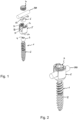
- Fig. 1:
- shows a perspective exploded view of a bone anchor according to a first embodiment in a polyaxial bone anchoring device.
- Fig. 2:
- shows a perspective view of the polyaxial bone anchoring device of
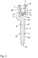
Fig. 1 in an assembled state. - Fig. 3:
- shows a cross-sectional view of the polyaxial bone anchoring device of
Figs. 1 and 2 , wherein the section is taken in a plane perpendicular to an inserted rod. - Fig. 4a:
- shows a side-view of the bone anchor according to the first embodiment as depicted in
Figs. 1 to 3 . - Fig. 4b:
- shows an enlarged view of a detail of
Fig. 4a . - Fig. 5a:
- shows a cross-sectional view of the bone anchor according to
Figs. 4a and 4b , wherein the section is taken in a plane including the shank axis and extending through a center of a head of the bone anchor. - Fig. 5b:
- shows an enlarged view of a detail of
Fig. 5a . - Fig. 6:
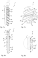
- shows an enlarged perspective view of a portion of the shank of a bone anchor according to a second embodiment.
- Fig. 7a:
- shows a side-view of the bone anchor according to the second embodiment.
- Fig. 7b:
- shows an enlarged view of a detail of
Fig. 7a . - Fig. 8a:
- shows a cross-sectional view of the bone anchor of
Figs. 6 to 7b , the cross-section taken in a plane including the shank axis and extending through a center of the head. - Fig. 8b:
- shows an enlarged view of a detail of
Fig. 8a . - Fig. 9a:
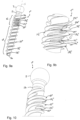
- shows a perspective of a bone anchor according to a third embodiment.
- Fig. 9b:
- shows an enlarged view of a detail of
Fig. 9a . - Fig. 10:
- shows an enlarged view of a portion of the bone anchor of
Fig. 9a including the head, wherein the bone anchor is rotated compared to the view inFig. 9a . - Fig. 11a:
- shows a side-view of the bone anchor of
Figs. 9a to 10 . - Fig. 11b:
- shows an enlarged view of a detail of
Fig. 11a . - Fig. 12a:
- shows a cross-sectional view of the bone anchor of
Figs. 11a and 11b , wherein the section is taken in a plane including the shank axis and extending through the center of the head. - Fig. 12b:
- shows an enlarged view of a detail of
Fig. 12a . - Fig. 13:
- shows a perspective view of a portion of the shank of a bone anchor according to a fourth embodiment.
- Fig. 14a:
- shows a side-view of the bone anchor according to the fourth embodiment.
- Fig. 14b:
- shows an enlarged view of a detail of
Fig. 14a . - Fig. 15a:
- shows a cross-sectional view of the bone anchor of
Figs. 14a and 14b , the section taken in a plane including the shank axis and extending through a center of the head. - Fig. 15b:
- shows an enlarged view of a detail of
Fig. 15a . - Fig. 16a:
- shows a side-view of a bone anchor according to a fifth embodiment.
- Fig. 16b:
- shows an enlarged perspective view of a detail of
Fig. 16a . - Fig. 17a:
- shows a cross-sectional view of the bone anchor of
Figs. 16a and 16b , the section taken in a plane including the shank axis and extending through a center of the head. - Fig. 17b:
- shows an enlarged view of a detail of
Fig. 17a . - Fig. 18a:
- shows a perspective view of a bone anchor according to a sixth embodiment.
- Fig. 18b:
- shows an enlarged view of a detail of
Fig. 18a . - Fig. 19a:
- shows a cross-sectional view of the bone anchor of
Figs. 18a and 18b , the section taken in a plane including the shank axis and extending through a center of the head. - Fig. 19b:
- shows an enlarged view of a detail of
Fig. 19a . - Referring to
Figs. 1 to 3 , a first embodiment of thebone anchor 1 is shown as a part of a polyaxial bone anchoring device. Thebone anchor 1 comprises ashank 2 to be anchored in bone and ahead 3 at a free end of theshank 2. Thehead 3 may comprise arecess 4 configured for engagement with screwing-in tool. A receivingpart 5 of the polyaxial bone anchoring device is configured to receive thehead 3 of the bone anchor and arod 500 in such a manner that thehead 3 can pivot within the receiving part to assume various angular positions with respect to the receivingpart 5 and the insertedrod 500. The polyaxial bone anchoring device further includes apressure member 6 for exerting pressure onto thehead 3 to lock thehead 3 within the receivingpart 5. Alocking device 7 which may be a set screw is configured to cooperate with the receivingpart 5 and to press onto therod 100 to fix the rod which in turn transfers the pressure onto thepressure member 6 to lock thehead 3 in the receivingpart 5. - The receiving
part 5 comprises a first orupper end 5a and an opposite second or lower end 5b and apassage 51 extending from thefirst end 5a to the second end 5b. Adjacent to the second 5a, aseat 52 that may have a substantially spherical shape is provided for pivotably receiving thehead 3 therein. Therod 500 can be inserted into achannel 53 formed by a substantially U-shaped recess extending from thefirst end 5a to a distance from the second end 5b. Adjacent to thefirst end 5a, aninternal thread 54 may be provided in the receivingpart 5 so that thelocking device 7 can be screwed into the receivingpart 5. Thepressure member 6 is adapted to move within thepassage 51 of the receiving part and comprises a substantiallyspherical recess 61 on its side facing the insertedhead 3 that is configured to contact the spherical outer surface portion of thehead 3. On the opposite side, a substantially cylinder segment-shapedrecess 62 is formed for providing a support surface for therod 100. Acoaxial hole 63 provides access for a tool to thehead 3 when thehead 3 is within the receiving part. - It shall be noted, that the
bone anchor 1 is not limited to be used with the polyaxial bone anchoring device described above. It can be combined with various other receiving parts of different design and various other pressure members, locking devices or rods as those shown in the Figures. - As further shown in
Figs. 4a to 5b , theshank 2 has a first end 2a that is configured to enter the bone first and an oppositesecond end 2b. At the first end 2a, a tip may be formed that may be blunt or sharp. Adjacent to thesecond end 2b of theshank 2, a neck 2c with a reduced outer diameter may be provided that continues into thehead 3. Thehead 3 preferably has a spherical outer surface portion, in particular, thehead 3 may have the shape of spherical segment with a substantially flat end surface 3a. Theentire bone anchor 1 may optionally be cannulated. It comprises achannel 8 extending fully from the free end surface 3a of thehead 3 through theshank 2 up to the tip. Thechannel 8 is preferably coaxial with the shank axis S and has a circular cross-section. An inner diameter of the channel may be substantially constant over the length or may vary along the length and/or the cross-section may be other than circular. - The
shank 2 comprises acore 10 and athread 20 winding in a helix around thecore 10 in a plurality of turns. A central longitudinal axis S of theshank 2, the shank axis, is also the screw axis of thethread 20. The core 10 may be cylindrical along most of the length of theshank 2. In greater detail, thecore 10 may be cylindrical between thesecond end 2b and a distance from the first end 2a with an outer diameter or core diameter that is the same or that may be greater than the outer diameter of the neck 2c. Also, thecore 10 may taper in a region towards the first end 2a. In this embodiment, thethread 20 is a double thread comprising two thread entries and therefore afirst helix 201 and asecond helix 202 that are winding in an alternating manner aroundcore 10. Thehelices second helix 202 runs in the middle between adjacent turns of thefirst helix 201. Moreover, the thread entries of the double thread are offset by 180°. The thread pitch P and geometry of thethread 20 may be such that there is gap between the thread turns on thecore 10. Generally, the thread shape and the thread pitch is such that thethread 20 is adapted to engage bone. A specific thread shape, the pitch, the number of threads, etc. are parameters that may depend on the type of bone which the anchor is to be inserted and on the purpose of the bone anchor. The shank may also have thread free portions, i.e. thethread 20 may be present only in a portion or portions of the shank. - An axial length of the
thread 20 preferably extends from the first end 2a of theshank 2 to thesecond end 2b. In a first axial thread section s1 adjacent to or close to the first end 2a and preferably extending up to or beyond the middle of theshank 2, thethread 20 comprises a a plurality of turns. The shape of thethread 20 is substantially defined at least by alower flank 20a facing towards the first end 2a and anupper flank 20b facing towards the second end of theshank 2 as present in the first thread section s1. Between thelower flank 20a and theupper flank 20b and, a substantiallyflat crest 20c of thethread 20 may be formed. In greater detail, parameters such as the shape of the flanks, the angle that the flanks form with each other, the thickness of the thread in the axial direction, the cross-section of the thread may all contribute to define the thread shape. Generally, the thread shape of thethread 20 may have any shape that is configured to engage bone. For example, it can have a V-shape with sharp, flat or rounded crest. Thus, for the following, the thread shape of thethread 20 in the thread section s1 is referred to as regular thread shape. In addition, in the first thread section s1, thethread 20 may run out towards the first end 2a. It shall be noted that thethread 20 may include cutting structures (not shown), for example axial grooves, close to the first end or at a distance therefrom which are disregarded in the definition of the regular shape of thethread 20. - In a second axial thread section s2 that is located closer to the
second end 2b than to the first end 2a of theshank 2, an additional thread structure is provided. Preferably, the second axial thread section s2 is at such a position that the additional thread structure is configured to engage the cortical bone when the bone anchor is fully inserted in bone. Thereby, the additional thread structure may increase the holding force that holds the bone anchor in the bone and/or may increase a resistance against loosening and/or pull-out of the bone anchor. In the embodiment, the additional thread structure comprises a modifiedthread 21 that is modified with respect to the regular thread shape as present in the first section s1. Preferably the modifiedthread 21 comprises at least one turn of the helix. - The modified
thread 21 forming the additional thread structure comprises an upper flank 21b facing towards thesecond end 2b of theshank 2 and alower flank 21a facing towards the first end 2a of theshank 2. The upper flank 21b is coincident with theupper flank 20b of thethread 20. In other words, the upper flank 21b of thethread 21 has the same shape and size as the upper flank of thethread 20 and merges continuously with theupper flank 20b of thethread 20 at a transition section s3 of the first section s1 and the second section s2. Thelower flank 21a is in the axial direction shifted or offset towards the first end 2a as compared to thelower flank 20a of the regular thread shape of thethread 20 in the first section s1. Moreover, thelower flank 21a is separated from the upper flank 21b by ahelical slit 22. By means of theslit 22 anadditional helix 24 that comprises thelower flank 21a is formed in the second thread section s2 for each of thehelices 201 andhelix 202. Theadditional helix 24 is shifted towards the first end 2a compared to the helix of thethread 20. By means of this, the thickness of the thread in the axial direction is increased compared to the regular thread shape. In thelower flank 21a,transverse slits 26 are formed that are open towards the outer free edge of thelower flank 21a. Thetransverse slits 26 form an angle with the shank axis S that may be the same as the flank angle of thelower flank 21a. By means of theslits 26, theadditional helix 24 is divided intosegments 24a. The thickness of theadditional helix 24 in the axial direction is such that theadditional helix 24 is flexible to some extent in the axial direction. In greater detail, theadditional helix 24 is flexible against the remaining portion of thethread 20 in the second thread section s2. To achieve a desired flexibility, the number and/or width of theslits 26 are selected. The position of theslits 24 along theadditional helix 24 of thefirst helix 201 and of thesecond helix 202 of the thread are offset from each other. Thus, thesegments 24a are also offset from each other from one turn to a next turn and/or from thefirst helix 201 to thesecond helix 202 seen in the axial direction. - In the embodiment, the second section s2 extends along an axial length that is only a little smaller than a half of the shank length. However, the second section is not restricted to such a length. In particular, it can have a length that comprises at minimum a single turn of the
additional helix 24 and at maximum extends up to a distance from the first end 2a that corresponds to a single turn of thethread 20. - The bone anchor may be made of any bio-compatible material, preferably however of titanium or stainless steel or of any other bio-compatible metal or metal alloy or plastic material. As a bio-compatible alloy, a NiTi alloy, for example Nitinol, may be used. Other materials can also be magnesium or magnesium alloys. Bio-compatible plastic materials for use may be, for example, polyether ether ketone (PEEK) or poly-L-lactide acid (PLLA). The receiving part and other parts of the polyaxial bone anchoring device may be made of the same or a different material.
- Preferably, the bone anchor is preferably using an additive manufacturing method. In an additive manufacturing method, the bone anchor is built up layer-by-layer based on three-dimensional data that characterize the shape and size of the bone anchor. A preferred method is, for example, selective laser sintering or selective laser melting or electron beam melting according to which successive layers of a powder material, for example stainless steel or titanium or another body compatible material are sintered or melted at positions corresponding to the cross-section of the bone anchor in the respective layer until the bone anchor is completed. With an additive manufacturing method, the additional thread structure is easily manufactured. Moreover, recesses that form undercuts and complex shapes can be built-up. In the above embodiment, the manufacture of the
additional helix 24 and theslit 22 can be made easily with such an additive method as a subtractive method would be too difficult or even impossible. - In use, the
bone anchor 1 usually is inserted into a prepared core hole in the bone, for example into the pedicle of a vertebra. The first thread section s1 is configured to be anchored in the softer cancellous bone. The second thread section s2 with the additional thread structure in the form of the modifiedthread 21 is configured to engage the harder cortical bone. During the insertion process and/or the final placement, theadditional helix 24 is slightly compressed towards the upper flank 21b. Thereby, the upper flank 21b and thelower flank 21a tensioned or pre-loaded against each other and in the bone. This can increase the holding force which holds the bone anchor in the bone. Furthermore, thesegments 24a of theadditional helix 24 can act as barbs that provide additional resistance against loosening, backing-out or against inadvertent screwing-back of the bone anchor. - Referring to
Figs. 6 to 8b a bone anchor 1' according to a second embodiment will be described. Parts and portions that are identical or highly similar of the bone anchor of the first embodiment are marked with the same reference numerals and the description thereof will not be repeated. The thread 20' of the first thread section s1 shown in this embodiment has a substantiallysharp crest 20c and the thickness of the thread in the axial direction is smaller than that of thethread 20 according to the first embodiment. However, it shall be noted that the thread 20' may also have an identical regular thread shape as thethread 20 of the first embodiment. Also in this embodiment, the thread 20' that defines the regular thread shape is a double thread with two helices 201' and 202'. The additional thread structure comprises a modified thread 21' in the second thread section s2 which lies on the same helix as the thread 20' of the first thread section s1 but which is bifurcated by a slit 22' into an upper helix 21b' and alower helix 21a'. Moreover, the additional thread structure also comprises a helical recess 25' in the core 10 that may have substantially the same helical extension as the slit 22'. As best seen inFig. 8b , the helical recess 25' extends under the upper helix 21b' and thelower helix 21a' such that they are separated from thecore 10. By means of this, the upper helix 21b' and thelower helix 21a' may be partially resilient with respect to the core 10 in the region where the recess 25' is that forms an undercut. - The thickness of the thread 21' formed by the helices 21b' and 21a' in the axial direction is greater than that of the thread 20' of the first thread section s1. In other words, the helix of the modified thread 21' is thickened compared to the helix of the thread 20'. The shape and size of the slit 22' is selected such that the
lower helix 21a' is flexible relative to the upper helix 21b'. In the embodiment, the additional thread structure in the form of the modified thread 21' includes alower step 26a where the thickened portion begins and that is located in the direction of the first end 2a of the shank and ends with anupper step 2b where the thickened portion stops and that is in the direction of thesecond end 2b of theshank 2. As depicted inFig. 7b , since each of the two helices 201' and 202' has the modified thread 21', thestep 26a belongs to the beginning of the thickened portion of the helix 201' and the step 26b belongs to the end of the thickened portion of the helix 202'. Moreover, the thickened portion of the first helix 201' is offset from the thickened portion of the second helix 202' of the double thread. Thehelical slit 22 begins before thelower step 26a in the helical path towards the first end 2a and ends beyond the upper step 26b in the direction in the helical path to thesecond end 2b. An axial coverage of the modified thread 21' is preferably about half a turn, but it can be less or mor up to about one turn. - Adjacent to the neck 2c, a small axial portion of the thread 20' with the regular thread shape may be present, as for example shown in
Fig. 7a . - In use, when the additional thread structure comprising the bifurcated thread 21' enters the bone, preferably the cortical bone region, the upper helix 21b' and the
lower helix 21a' are pressed together. This is caused by the increased thickness of the modified thread 21' in the second thread section s2 and the flexibility of the helices 21b' and 21a' due to the slit 22'. In addition, the helices 21b' and 21a' can resiliently flex to some extent with regard to thecore 10. Thereby, the two helices 21b' and 21a' may be tensioned or pre-loaded against each other and against the bone which results in an additional holding force of the bone anchor in the bone. Also, the slit 22' and the recess 25' may provide space for ingrowth of bone material that further reduces the risk of loosening. - Referring to
Figs. 9a to 12b , abone anchor 1" according to a third embodiment will be described. Parts and portions of the third embodiment that are identical or highly similar to that of the previous embodiments are marked with the same reference numerals and the description thereof will not be repeated. Thethread 20" that defines the regular thread shape may be identical to the thread 20' of the second embodiment. However, it may also be identical to thethread 20 of the first embodiment. The additional thread structure comprises twoadditional helices 211" and 212" in the second section s2 that run between the twohelices 20"1 and 20"2 of thethread 20". Theadditional helices 211" and 212" have thread entries that are offset from each other by 180°. Eachadditional helix 211", 212" is composed of two differently arranged portions. Afirst portion 21a" is extending axially in the middle between thehelices 201" and 202" of thethread 20". A second portion 21b" that is closer to thesecond end 2b than thefirst portion 21a" is in the axial direction slightly shifted towards thesecond end 2b of theshank 2. The second portion 21b" preferably extends along a half turn of each of thehelices 211", 212". Thefirst portion 21a" and the second portion 21b" taper towards atransition portion 21c" where they join each other. Adjacent to the second portion 21b" athird portion 21c" may be formed in the direction to thesecond end 2b of theshank 2, that is again located in the middle between thehelices 202" and 201" like thefirst portion 21a". Thefirst helix portion 21a" and the second helix portion 21b" of oneadditional helix 211" are arranged offset from those of the secondadditional helix 212", preferably in such a manner that axially first and second portions alternate from one helix to the next helix. - Furthermore, the additional thread structure includes helix-shaped recesses or undercuts 25" in the core 10 that extend under the the
additional helices 211" and 212" at least in a portion thereof such that theadditional helices 211" and 212" are partially separated from thecore 10. The helix-shapedrecesses 25" in the core cover at least a region along the second portion 21b", preferably they extend partially also under thefirst portion 21a". By means of theserecesses 25", the modifiedthread 21" is flexible to some extent with respect to thecore 10. - It should be noted that the second thread section s2 may cover several turns of the
thread 20". In such a case,first portions 21a" and second portions 21b" and the corresponding helix-shapedrecesses 25" are arranged one after the other in an alternating manner and are joined bythinner transition portions 21c". The thickness of the additional helices may be smaller than the thickness of the helices of thethread 20". - In use, as depicted in particular in
Fig. 12b , when the additional thread structure engages the bone, in particular the cortical bone, the second portions 21b" of the additional helices that form a type of ramp experience a force with a downward component as indicated by the arrows that generates a pre-load that enhances the holding force. Moreover, the resistance against loosening, screwing-out or pull-out may be increased. - Referring to
Figs. 13 to 15b abone anchor 1‴ according to a fourth embodiment will be described. Parts and portions of the bone anchor according to the fourth embodiment that are identical or highly similar to those of the previous embodiments are marked with the same reference numerals and the description thereof will not be repeated. Thebone anchor 1‴ according to the fourth embodiment differs from thebone anchor 1" according to the third embodiment in that the additional thread structure comprises a singleadditional helix 21‴ that runs between twoturns 201‴ and 202‴ of thethread 20‴ and a recess or undercut 25‴ that separates at least a portion of theadditional helix 21‴ from thecore 10. The structure of the singleadditional helix 21‴ is the same as one of theadditional helices 211" and 212" of the third embodiment. - In use, as shown in
Fig. 15b , when the bone anchor according to the fourth embodiment is inserted into bone and the second section s2 engages the cortical bone, a downward force as depicted with the arrows is generated onto theadditional helix 21‴. This may result in a tension or pre-load between the flanks of the additional helix and the bone that may increase the holding force. Moreover, this may increase a resistance against loosening, screwing-back or pull-out. - Referring to
Figs. 16a to 17b , a bone anchor 1ʺʺ according to a fifth embodiment of the bone anchor is shown. Parts and portions of the bone anchor 1ʺʺ according to the fifth embodiment that are identical or highly similar to parts and portions of the previous embodiments are marked with the same reference numerals and the description thereof will not be repeated. The bone anchor 1ʺʺ according to the fifth embodiment comprises a thread 20ʺʺ which is a double thread having afirst helix 201ʺʺ and asecond helix 202ʺʺ similar to that of the third embodiment in a first thread section s1 adjacent to the first end 2a of theshank 2. Thelower flank 20a and theupper flank 20b form an angle α which is shown inFig. 17a only schematically. Theshank 2 further comprises a second thread section s2 that covers the shank from an end of the first thread section s1 up to thesecond end 2b and in which an additional thread structure with a modified thread 21ʺʺ is provided. The thread 21ʺʺ is modified such that the lower flank 21aʺʺ and the upper flank 21bʺʺ form a second angle β hat is greater than the first angle α of the thread 20ʺʺ. Thereby, the thickness of the thread is increased. This also enhances the holding force, particular in cortical bone. - A still further additional thread structure is formed by a plurality of at least partially helix-shaped recesses 27ʺʺ in the first thread section s1, i.e. in the
helices 201ʺʺ and 202ʺʺ. Therecesses 27"" extend in the axial direction entirely through the thread from theupper flank 20b to thelower flank 20a. The recesses 27ʺʺ are are elongate and follow the helical course of thethread 20"". A length of the recesses 27ʺʺ may be about a quarter of a turn. The crest 7c in the region of the recesses 27ʺʺ remains intact. Thus, the recesses 27ʺʺ are closed in the radially outward direction. In each of thehelices 201ʺʺ and 202ʺʺ at least one single recess 27ʺʺ may be formed wherein the positions of the recesses are offset from each other from one helix to the other. - In use, the additional thread structure in the form of the increased thickness of the thread provides for an enhanced holding force. The additional thread structure in the form of the recesses may allow an increased ingrowth of bone material. As the position of the recesses 27ʺʺ is closer to the middle of the shank of the bone anchor, the additional thread structure enhances the holding force, in particular in cancellous bone.
- Referring to
Figs. 18a to 19b abone anchor 100 according to a sixth embodiment will be described. Parts and portions of the bone anchor according to the sixth embodiment that are identical or similar to parts and portions of the bone anchor according to previous embodiments are marked with the same reference numerals and the description thereof will not be repeated. Thebone anchor 100 according to the sixth embodiment differs in some aspects from the bone anchor according to the previous embodiments. It comprises athread 200 that defines the regular thread shape and which is present in the first thread section s1. In the embodiment shown, thethread 200 is a double thread with a first helix 2001 asecond helix 2002. In the first thread section s1 theupper flank 20b and thelower flank 20a form an angle α. In the second thread section s2 thethread 200 is modified to adouble thread 210 having twohelices thread 210 comprises an angle β between the upper flank 210b and thelower flank 210a that is greater than the angle α of thethread 200 in the first section s1. Thus, the thickness of the modifiedthread 210 in the second section s2 is greater than the thickness of thethread 200 in the first section s1. Moreover, thecrest 20c may be more flat in the second section s2 compared to a more sharp crest in the first section s1. - Each of the helices in the second thread section s2 comprises a still further additional thread structure formed by at least one groove, preferably by two
grooves 270a, 270b that extend along the upper flank 210b and thelower flank 210a, respectively, in a helical path. The outer groove 270a that is on a radial outer position, closer to the crest 200c, may have a greater width in the transverse direction compared to theinner groove 270b that is closer to thecore 10. A transverse groove 270c may be provided to radially connect the outer groove 270a to theinner groove 270b at the starting area of thethread 210 that is facing towards the first end 2a. - In addition, a plurality of
recesses 280 extending substantially in the axial direction from theupper flank 20b to thelower flank 20a may be provided. Therecesses 280 are provided along an axial region between a distance from thesecond end 2b in the second thread section s2 and a distance from the first end 2a in the first thread section s1. In greater detail, therecesses 280 may be arranged in at least one, preferably two or more axial rows offset from each other as can be seen inFigs. 19a and 19b . The shape of therecesses 280 may be such that they have a rounded inner part closer to thecore 10 and a more flat outer part that is located still inside the thread flank. In other words, therecesses 280 are closed and do not interrupt the crest 200c. The number of the plurality ofrecesses 280 may be at least two, preferably more than three recesses in one axial row. Also, the axial distance of therecesses 280 in one row may be different from that of an other row as depicted inFig. 19a . - The
bone anchor 100 comprises ashort channel 80 that extends from the free end surface 3a of thehead 3 to a distance therefrom into the shank. - In use, with the modified
thread 210, the holding force can be increased due to the increased thickness of the modifiedthread 210. By means of thegrooves 270 the ingrowth of bone material and tissue is promoted. As a result, the holding force of the screw within the bone can be increased and/or the resistance against loosening, screwing-out or pull-out can be increased. - It shall be noted, that all embodiments of the bone anchor are preferably made by an additive manufacturing method as explained with respect to the first embodiment.
- Further modifications of the bone anchors may be conceivable. The features of the various bone anchors can be mixed and matched to produce a variety of further embodiments. The shape of the bone anchor is not limited to the detailed shape shown in the embodiments. For example, various designs of the tips of the bone anchor may be conceivable. The head may have other shapes or can be omitted at all. Even the neck portion can be omitted. A suitable drive structure is then formed at the second end of the shank. The additional thread structure can be provided at various positions along the shank. Furthermore, more than one section with an additional thread structure may be provided on the shank and the additional thread structures do not need to be identical on one shank.
- It should be noted that the core may also be tapered from the second end up to the first end of the shank or its outer diameter may decrease in steps between the second end and the first end of the shank. In a further embodiment the shank may be fenestrated, i.e. may have one or a plurality of openings that connect the channel with the outside of the bone anchor.
- The threads that form the regular thread shape may also be a single thread or a multiple thread with more than two thread entries. They may have any thread shape that is suitable for anchoring in bone.
Claims (15)
- Bone anchor comprisinga shank (2) configured to be anchored in bone, the shank (2) comprisinga first end (2a) configured to be inserted first and an opposite second end (2b) and a longitudinal axis (S) extending through the first end and the second end,a core (10) anda thread (20, 20′, 20ʺ, 20‴, 20ʺʺ, 200) configured to engage bone, the thread comprising a number of turns of a helix around the core (10), the number of turns defining an axial length of the thread, wherein the thread (20, 20′, 20ʺ, 20‴, 20ʺʺ, 200) comprises a lower flank (20a) facing towards the first end (2a) and an upper flank (20b) facing towards the second end (2b), the upper flank and the lower flank defining a thread shape;wherein an additional thread structure (21, 21′, 21ʺ, 21‴, 21ʺʺ, 210) with a modified thread shape is provided on a portion (s2) of the core (10) that is smaller than the axial length of the thread, the additional thread structure comprising a recess (22, 22′, 25′, 25ʺ, 25‴, 27ʺʺ, 270a, 270b) that is at least partially helix-shaped.
- The bone anchor of claim 1, wherein the additional thread structure (21, 21′, 21ʺ, 21‴, 21ʺʺ, 210) is closer to the second end of the shank than to the first end, preferably wherein the additional thread structure is at or close to the second end.
- The bone anchor of claim 1 or 2, wherein the recess (22, 22', 25', 25", 25"') is configured to render the additional thread structure at least partially flexible.
- The bone anchor of one of claims 1 to 3, wherein the recess is formed by a helix-shaped slit (22, 22') that separates the upper and the lower flank of the additional thread structure (21, 21') from each other.
- The bone anchor of claim 4, wherein the lower flank (21a, 21a') in the additional thread structure (21, 21') is offset from the lower flank (20a) of the thread, preferably towards the first end.
- The bone anchor of claim 4 or 5, wherein by the helix-shaped slit (22, 22′, 25′, 25ʺ, 25‴) the upper flank and the lower flank of the additional thread structure (21, 21′, 21ʺ, 21‴, 21ʺʺ) are resilient relative to each other in the axial direction, more preferably wherein the lower flank is flexible in the axial direction.
- The bone anchor of one of claims 1 to 6, wherein the additional thread structure (21) comprises one or more transverse slits (26) in the upper and/or the lower flank, preferably wherein the transverse slits extend at an angle different from 90° to the longitudinal axis.
- The bone anchor of one of claims 1 to 7, wherein the helix-shaped recess comprises a recessed portion (25′, 25ʺ, 25‴) in the core that separates at least a portion of the additional thread (21′, 21ʺ, 21‴) structure from the core.
- The bone anchor of one of claims 1 to 8, wherein the additional thread structure (21, 21', 21ʺʺ, 210) comprises a modified thread shape that is thickened compared to the thread shape of the thread (20, 20', 20ʺʺ, 200).
- The bone anchor of one of claims 1 to 9, wherein the the additional thread structure (21", 21‴) comprises at least one turn of a helix of an additional thread that runs between the turns of the helix of the thread (20ʺ, 20‴), preferably wherein the additional thread comprises a section (21bʺ, 21b‴) that is offset from a middle between the turns of the thread towards the second end (2b).
- The bone anchor of one of claims 1 to 10, wherein the at least partially helix-shaped recess is formed by an aperture (27ʺʺ) in the thread (20ʺʺ), the aperture (27ʺʺ) extending in an axial direction fully from the upper flank to the lower flank, preferably wherein a crest (20c) of the thread in the region around the aperture is intact, more preferably wherein the aperture along a portion of a turn of the thread.
- The bone anchor of claim 11, wherein a plurality of apertures (27ʺʺ) are provided, each in one turn of the helix of the thread, preferably wherein the apertures are arranged in such a way that they substantially do not overlap in the axial direction.
- The bone anchor of one of claims 1 to 12, wherein the at least partially helix-shaped recess comprises a at leats one groove (270a, 270b) extending in the upper flank and/or in the lower flank in a helix-shaped manner along the helix of the thread.
- The bone anchor of one of claims 1 to 13, wherein the thread (20, 20', 20ʺ, 20‴, 20ʺʺ, 200) is a multiple thread, preferably a double thread.
- The bone anchor of one of claims 1 to 14, wherein the shank (2) is manufactured using an additive manufacturing method.
Priority Applications (2)
| Application Number | Priority Date | Filing Date | Title |
|---|---|---|---|
| EP22155488.4A EP4223240B1 (en) | 2022-02-07 | 2022-02-07 | Bone anchor |
| US18/165,168 US12636054B2 (en) | 2022-02-07 | 2023-02-06 | Bone anchor |
Applications Claiming Priority (1)
| Application Number | Priority Date | Filing Date | Title |
|---|---|---|---|
| EP22155488.4A EP4223240B1 (en) | 2022-02-07 | 2022-02-07 | Bone anchor |
Publications (2)
| Publication Number | Publication Date |
|---|---|
| EP4223240A1 true EP4223240A1 (en) | 2023-08-09 |
| EP4223240B1 EP4223240B1 (en) | 2025-01-29 |
Family
ID=80222581
Family Applications (1)
| Application Number | Title | Priority Date | Filing Date |
|---|---|---|---|
| EP22155488.4A Active EP4223240B1 (en) | 2022-02-07 | 2022-02-07 | Bone anchor |
Country Status (2)
| Country | Link |
|---|---|
| US (1) | US12636054B2 (en) |
| EP (1) | EP4223240B1 (en) |
Families Citing this family (4)
| Publication number | Priority date | Publication date | Assignee | Title |
|---|---|---|---|---|
| US10413332B2 (en) * | 2016-04-25 | 2019-09-17 | Imds Llc | Joint fusion implant and methods |
| CN116983062B (en) * | 2023-08-11 | 2026-01-30 | 尤尼泰科(重庆)医疗科技有限公司 | A type of orthopedic bone screw |
| US20250186220A1 (en) * | 2023-12-12 | 2025-06-12 | Ht Medical, Llc | Sacroiliac fusion screw |
| WO2026122923A1 (en) * | 2024-12-05 | 2026-06-11 | Orthopediatrics Corp. | Pedicle screw system and method of installing the same |
Citations (7)
| Publication number | Priority date | Publication date | Assignee | Title |
|---|---|---|---|---|
| US20080249579A1 (en) * | 2007-04-04 | 2008-10-09 | Warsaw Orthopedic, Inc. | Variable flank bone screw |
| US20110276095A1 (en) | 2008-12-09 | 2011-11-10 | Yossef Bar | Double Threaded Orthopedic Screw |
| US20120232600A1 (en) * | 2009-11-20 | 2012-09-13 | Shanghai Microport Orthopedics Co., Ltd. | Bone screw |
| US20140329202A1 (en) * | 2011-07-20 | 2014-11-06 | Parsa T. Zadeh | Self-osteotomizing bone implant and related method |
| US20180325570A1 (en) * | 2017-05-12 | 2018-11-15 | Cutting Edge Spine Llc | Implants for tissue fixation and fusion |
| US10531904B2 (en) | 2014-04-30 | 2020-01-14 | Eric D. Kolb | Bone screw with apertures |
| FR3102924A1 (en) * | 2019-11-07 | 2021-05-14 | Olivier LEVRIER | Reinforced secondary stability trans-pedicle anchor screw |
Family Cites Families (9)
| Publication number | Priority date | Publication date | Assignee | Title |
|---|---|---|---|---|
| US5120171A (en) | 1990-11-27 | 1992-06-09 | Stuart Surgical | Bone screw with improved threads |
| US20140121703A1 (en) | 2012-10-31 | 2014-05-01 | Roger P. Jackson | Polyaxial bone anchor with pop-on multi-thread shank, some with diametric interference fit inserts |
| EP2442740A1 (en) | 2009-06-19 | 2012-04-25 | US Spine, Inc. | Triple lead bone screw |
| DE202012002636U1 (en) | 2011-11-07 | 2013-02-08 | Biomed Est. | Screw implant for a jawbone with coronal compression thread and apical self-tapping thread |
| US20140336709A1 (en) | 2013-03-13 | 2014-11-13 | Baxano Surgical, Inc. | Multi-threaded pedicle screw system |
| US20140277190A1 (en) | 2013-03-14 | 2014-09-18 | Howmedica Osteonics Corp. | Compression screw with variable pitch thread |
| US9463057B2 (en) * | 2014-01-16 | 2016-10-11 | Amendia, Inc. | Orthopedic fastener |
| US10188430B2 (en) | 2015-11-16 | 2019-01-29 | Clariance | Double-threaded bone screw |
| CN110198679B (en) | 2017-01-09 | 2022-03-15 | 捷迈有限公司 | Multi-shaft fixing column |
-
2022
- 2022-02-07 EP EP22155488.4A patent/EP4223240B1/en active Active
-
2023
- 2023-02-06 US US18/165,168 patent/US12636054B2/en active Active
Patent Citations (7)
| Publication number | Priority date | Publication date | Assignee | Title |
|---|---|---|---|---|
| US20080249579A1 (en) * | 2007-04-04 | 2008-10-09 | Warsaw Orthopedic, Inc. | Variable flank bone screw |
| US20110276095A1 (en) | 2008-12-09 | 2011-11-10 | Yossef Bar | Double Threaded Orthopedic Screw |
| US20120232600A1 (en) * | 2009-11-20 | 2012-09-13 | Shanghai Microport Orthopedics Co., Ltd. | Bone screw |
| US20140329202A1 (en) * | 2011-07-20 | 2014-11-06 | Parsa T. Zadeh | Self-osteotomizing bone implant and related method |
| US10531904B2 (en) | 2014-04-30 | 2020-01-14 | Eric D. Kolb | Bone screw with apertures |
| US20180325570A1 (en) * | 2017-05-12 | 2018-11-15 | Cutting Edge Spine Llc | Implants for tissue fixation and fusion |
| FR3102924A1 (en) * | 2019-11-07 | 2021-05-14 | Olivier LEVRIER | Reinforced secondary stability trans-pedicle anchor screw |
Also Published As
| Publication number | Publication date |
|---|---|
| US20230248408A1 (en) | 2023-08-10 |
| US12636054B2 (en) | 2026-05-26 |
| EP4223240B1 (en) | 2025-01-29 |
Similar Documents
| Publication | Publication Date | Title |
|---|---|---|
| EP4223240B1 (en) | Bone anchor | |
| US11583320B2 (en) | Implant for bones or vertebrae with self-constrained flexibility | |
| US10905482B2 (en) | Bone anchoring element | |
| EP1825826B1 (en) | Bone anchoring device | |
| US8292932B2 (en) | Bone anchoring element | |
| US9198702B2 (en) | Bone screw | |
| US12408962B2 (en) | Bone anchor | |
| EP1741400B1 (en) | Bone anchoring element | |
| EP2749239B1 (en) | Dynamic bone anchor | |
| US20110288588A1 (en) | System and method for facet fixation and fusion | |
| JP2007530216A (en) | Double lead bone screw | |
| EP4082458A1 (en) | Bone screw | |
| EP4663140A1 (en) | Screw element for use in spinal, orthopaedic or trauma surgery | |
| EP4052672A1 (en) | Bone anchor |
Legal Events
| Date | Code | Title | Description |
|---|---|---|---|
| PUAI | Public reference made under article 153(3) epc to a published international application that has entered the european phase |
Free format text: ORIGINAL CODE: 0009012 |
|
| STAA | Information on the status of an ep patent application or granted ep patent |
Free format text: STATUS: REQUEST FOR EXAMINATION WAS MADE |
|
| 17P | Request for examination filed |
Effective date: 20220825 |
|
| AK | Designated contracting states |
Kind code of ref document: A1 Designated state(s): AL AT BE BG CH CY CZ DE DK EE ES FI FR GB GR HR HU IE IS IT LI LT LU LV MC MK MT NL NO PL PT RO RS SE SI SK SM TR |
|
| P01 | Opt-out of the competence of the unified patent court (upc) registered |
Effective date: 20230901 |
|
| GRAP | Despatch of communication of intention to grant a patent |
Free format text: ORIGINAL CODE: EPIDOSNIGR1 |
|
| STAA | Information on the status of an ep patent application or granted ep patent |
Free format text: STATUS: GRANT OF PATENT IS INTENDED |
|
| RIC1 | Information provided on ipc code assigned before grant |
Ipc: F16B 33/02 20060101ALI20240912BHEP Ipc: F16B 25/00 20060101ALI20240912BHEP Ipc: F16B 7/04 20060101ALI20240912BHEP Ipc: A61B 17/86 20060101ALI20240912BHEP Ipc: A61B 17/70 20060101AFI20240912BHEP |
|
| INTG | Intention to grant announced |
Effective date: 20241008 |
|
| GRAS | Grant fee paid |
Free format text: ORIGINAL CODE: EPIDOSNIGR3 |
|
| GRAA | (expected) grant |
Free format text: ORIGINAL CODE: 0009210 |
|
| STAA | Information on the status of an ep patent application or granted ep patent |
Free format text: STATUS: THE PATENT HAS BEEN GRANTED |
|
| AK | Designated contracting states |
Kind code of ref document: B1 Designated state(s): AL AT BE BG CH CY CZ DE DK EE ES FI FR GB GR HR HU IE IS IT LI LT LU LV MC MK MT NL NO PL PT RO RS SE SI SK SM TR |
|
| REG | Reference to a national code |
Ref country code: GB Ref legal event code: FG4D |
|
| REG | Reference to a national code |
Ref country code: CH Ref legal event code: EP |
|
| REG | Reference to a national code |
Ref country code: DE Ref legal event code: R096 Ref document number: 602022009892 Country of ref document: DE |
|
| REG | Reference to a national code |
Ref country code: IE Ref legal event code: FG4D |
|
| PGFP | Annual fee paid to national office [announced via postgrant information from national office to epo] |
Ref country code: AT Payment date: 20250417 Year of fee payment: 4 |
|
| REG | Reference to a national code |
Ref country code: NL Ref legal event code: MP Effective date: 20250129 |
|
| PG25 | Lapsed in a contracting state [announced via postgrant information from national office to epo] |
Ref country code: NL Free format text: LAPSE BECAUSE OF FAILURE TO SUBMIT A TRANSLATION OF THE DESCRIPTION OR TO PAY THE FEE WITHIN THE PRESCRIBED TIME-LIMIT Effective date: 20250129 |
|
| PG25 | Lapsed in a contracting state [announced via postgrant information from national office to epo] |
Ref country code: RS Free format text: LAPSE BECAUSE OF FAILURE TO SUBMIT A TRANSLATION OF THE DESCRIPTION OR TO PAY THE FEE WITHIN THE PRESCRIBED TIME-LIMIT Effective date: 20250429 |
|
| PG25 | Lapsed in a contracting state [announced via postgrant information from national office to epo] |
Ref country code: FI Free format text: LAPSE BECAUSE OF FAILURE TO SUBMIT A TRANSLATION OF THE DESCRIPTION OR TO PAY THE FEE WITHIN THE PRESCRIBED TIME-LIMIT Effective date: 20250129 |
|
| PG25 | Lapsed in a contracting state [announced via postgrant information from national office to epo] |
Ref country code: PL Free format text: LAPSE BECAUSE OF FAILURE TO SUBMIT A TRANSLATION OF THE DESCRIPTION OR TO PAY THE FEE WITHIN THE PRESCRIBED TIME-LIMIT Effective date: 20250129 |
|
| PG25 | Lapsed in a contracting state [announced via postgrant information from national office to epo] |
Ref country code: ES Free format text: LAPSE BECAUSE OF FAILURE TO SUBMIT A TRANSLATION OF THE DESCRIPTION OR TO PAY THE FEE WITHIN THE PRESCRIBED TIME-LIMIT Effective date: 20250129 |
|
| REG | Reference to a national code |
Ref country code: LT Ref legal event code: MG9D |
|
| PG25 | Lapsed in a contracting state [announced via postgrant information from national office to epo] |
Ref country code: IS Free format text: LAPSE BECAUSE OF FAILURE TO SUBMIT A TRANSLATION OF THE DESCRIPTION OR TO PAY THE FEE WITHIN THE PRESCRIBED TIME-LIMIT Effective date: 20250529 Ref country code: NO Free format text: LAPSE BECAUSE OF FAILURE TO SUBMIT A TRANSLATION OF THE DESCRIPTION OR TO PAY THE FEE WITHIN THE PRESCRIBED TIME-LIMIT Effective date: 20250429 |
|
| REG | Reference to a national code |
Ref country code: AT Ref legal event code: MK05 Ref document number: 1762690 Country of ref document: AT Kind code of ref document: T Effective date: 20250129 |
|
| PG25 | Lapsed in a contracting state [announced via postgrant information from national office to epo] |
Ref country code: HR Free format text: LAPSE BECAUSE OF FAILURE TO SUBMIT A TRANSLATION OF THE DESCRIPTION OR TO PAY THE FEE WITHIN THE PRESCRIBED TIME-LIMIT Effective date: 20250129 |
|
| PG25 | Lapsed in a contracting state [announced via postgrant information from national office to epo] |
Ref country code: LV Free format text: LAPSE BECAUSE OF FAILURE TO SUBMIT A TRANSLATION OF THE DESCRIPTION OR TO PAY THE FEE WITHIN THE PRESCRIBED TIME-LIMIT Effective date: 20250129 Ref country code: PT Free format text: LAPSE BECAUSE OF FAILURE TO SUBMIT A TRANSLATION OF THE DESCRIPTION OR TO PAY THE FEE WITHIN THE PRESCRIBED TIME-LIMIT Effective date: 20250529 |
|
| PG25 | Lapsed in a contracting state [announced via postgrant information from national office to epo] |
Ref country code: BG Free format text: LAPSE BECAUSE OF FAILURE TO SUBMIT A TRANSLATION OF THE DESCRIPTION OR TO PAY THE FEE WITHIN THE PRESCRIBED TIME-LIMIT Effective date: 20250129 Ref country code: GR Free format text: LAPSE BECAUSE OF FAILURE TO SUBMIT A TRANSLATION OF THE DESCRIPTION OR TO PAY THE FEE WITHIN THE PRESCRIBED TIME-LIMIT Effective date: 20250430 |
|
| PG25 | Lapsed in a contracting state [announced via postgrant information from national office to epo] |
Ref country code: AT Free format text: LAPSE BECAUSE OF FAILURE TO SUBMIT A TRANSLATION OF THE DESCRIPTION OR TO PAY THE FEE WITHIN THE PRESCRIBED TIME-LIMIT Effective date: 20250129 |
|
| PG25 | Lapsed in a contracting state [announced via postgrant information from national office to epo] |
Ref country code: SE Free format text: LAPSE BECAUSE OF FAILURE TO SUBMIT A TRANSLATION OF THE DESCRIPTION OR TO PAY THE FEE WITHIN THE PRESCRIBED TIME-LIMIT Effective date: 20250129 |
|
| PG25 | Lapsed in a contracting state [announced via postgrant information from national office to epo] |
Ref country code: SM Free format text: LAPSE BECAUSE OF FAILURE TO SUBMIT A TRANSLATION OF THE DESCRIPTION OR TO PAY THE FEE WITHIN THE PRESCRIBED TIME-LIMIT Effective date: 20250129 |
|
| PG25 | Lapsed in a contracting state [announced via postgrant information from national office to epo] |
Ref country code: DK Free format text: LAPSE BECAUSE OF FAILURE TO SUBMIT A TRANSLATION OF THE DESCRIPTION OR TO PAY THE FEE WITHIN THE PRESCRIBED TIME-LIMIT Effective date: 20250129 |
|
| PG25 | Lapsed in a contracting state [announced via postgrant information from national office to epo] |
Ref country code: MC Free format text: LAPSE BECAUSE OF FAILURE TO SUBMIT A TRANSLATION OF THE DESCRIPTION OR TO PAY THE FEE WITHIN THE PRESCRIBED TIME-LIMIT Effective date: 20250129 |
|
| PG25 | Lapsed in a contracting state [announced via postgrant information from national office to epo] |
Ref country code: LU Free format text: LAPSE BECAUSE OF NON-PAYMENT OF DUE FEES Effective date: 20250207 Ref country code: IT Free format text: LAPSE BECAUSE OF FAILURE TO SUBMIT A TRANSLATION OF THE DESCRIPTION OR TO PAY THE FEE WITHIN THE PRESCRIBED TIME-LIMIT Effective date: 20250129 |
|
| PG25 | Lapsed in a contracting state [announced via postgrant information from national office to epo] |
Ref country code: CZ Free format text: LAPSE BECAUSE OF FAILURE TO SUBMIT A TRANSLATION OF THE DESCRIPTION OR TO PAY THE FEE WITHIN THE PRESCRIBED TIME-LIMIT Effective date: 20250129 Ref country code: EE Free format text: LAPSE BECAUSE OF FAILURE TO SUBMIT A TRANSLATION OF THE DESCRIPTION OR TO PAY THE FEE WITHIN THE PRESCRIBED TIME-LIMIT Effective date: 20250129 |
|
| PG25 | Lapsed in a contracting state [announced via postgrant information from national office to epo] |
Ref country code: RO Free format text: LAPSE BECAUSE OF FAILURE TO SUBMIT A TRANSLATION OF THE DESCRIPTION OR TO PAY THE FEE WITHIN THE PRESCRIBED TIME-LIMIT Effective date: 20250129 |
|
| PG25 | Lapsed in a contracting state [announced via postgrant information from national office to epo] |
Ref country code: SK Free format text: LAPSE BECAUSE OF FAILURE TO SUBMIT A TRANSLATION OF THE DESCRIPTION OR TO PAY THE FEE WITHIN THE PRESCRIBED TIME-LIMIT Effective date: 20250129 |
|
| REG | Reference to a national code |
Ref country code: DE Ref legal event code: R097 Ref document number: 602022009892 Country of ref document: DE |
|
| PLBE | No opposition filed within time limit |
Free format text: ORIGINAL CODE: 0009261 |
|
| STAA | Information on the status of an ep patent application or granted ep patent |
Free format text: STATUS: NO OPPOSITION FILED WITHIN TIME LIMIT |
|
| REG | Reference to a national code |
Ref country code: BE Ref legal event code: MM Effective date: 20250228 |
|
| REG | Reference to a national code |
Ref country code: CH Ref legal event code: L10 Free format text: ST27 STATUS EVENT CODE: U-0-0-L10-L00 (AS PROVIDED BY THE NATIONAL OFFICE) Effective date: 20251210 |
|
| 26N | No opposition filed |
Effective date: 20251030 |
|
| PG25 | Lapsed in a contracting state [announced via postgrant information from national office to epo] |
Ref country code: FR Free format text: LAPSE BECAUSE OF NON-PAYMENT OF DUE FEES Effective date: 20250329 |
|
| PG25 | Lapsed in a contracting state [announced via postgrant information from national office to epo] |
Ref country code: BE Free format text: LAPSE BECAUSE OF NON-PAYMENT OF DUE FEES Effective date: 20250228 |
|
| PG25 | Lapsed in a contracting state [announced via postgrant information from national office to epo] |
Ref country code: IE Free format text: LAPSE BECAUSE OF NON-PAYMENT OF DUE FEES Effective date: 20250207 |
|
| REG | Reference to a national code |
Ref country code: CH Ref legal event code: U11 Free format text: ST27 STATUS EVENT CODE: U-0-0-U10-U11 (AS PROVIDED BY THE NATIONAL OFFICE) Effective date: 20260301 |
|
| PGFP | Annual fee paid to national office [announced via postgrant information from national office to epo] |
Ref country code: GB Payment date: 20260213 Year of fee payment: 5 |
|
| PGFP | Annual fee paid to national office [announced via postgrant information from national office to epo] |
Ref country code: DE Payment date: 20260224 Year of fee payment: 5 |
|
| PGFP | Annual fee paid to national office [announced via postgrant information from national office to epo] |
Ref country code: CH Payment date: 20260301 Year of fee payment: 5 |
|
| PG25 | Lapsed in a contracting state [announced via postgrant information from national office to epo] |
Ref country code: CY Free format text: LAPSE BECAUSE OF FAILURE TO SUBMIT A TRANSLATION OF THE DESCRIPTION OR TO PAY THE FEE WITHIN THE PRESCRIBED TIME-LIMIT Effective date: 20250129 |
|
| PG25 | Lapsed in a contracting state [announced via postgrant information from national office to epo] |
Ref country code: TR Free format text: LAPSE BECAUSE OF FAILURE TO SUBMIT A TRANSLATION OF THE DESCRIPTION OR TO PAY THE FEE WITHIN THE PRESCRIBED TIME-LIMIT Effective date: 20250129 |
|
| PG25 | Lapsed in a contracting state [announced via postgrant information from national office to epo] |
Ref country code: LT Free format text: LAPSE BECAUSE OF FAILURE TO SUBMIT A TRANSLATION OF THE DESCRIPTION OR TO PAY THE FEE WITHIN THE PRESCRIBED TIME-LIMIT Effective date: 20250129 |