EP4223238A1 - Devices, systems, and methods for cooling a surgical instrument - Google Patents
Devices, systems, and methods for cooling a surgical instrument Download PDFInfo
- Publication number
- EP4223238A1 EP4223238A1 EP23163972.5A EP23163972A EP4223238A1 EP 4223238 A1 EP4223238 A1 EP 4223238A1 EP 23163972 A EP23163972 A EP 23163972A EP 4223238 A1 EP4223238 A1 EP 4223238A1
- Authority
- EP
- European Patent Office
- Prior art keywords
- fluid
- blade
- lumen
- conduit
- cooling module
- Prior art date
- Legal status (The legal status is an assumption and is not a legal conclusion. Google has not performed a legal analysis and makes no representation as to the accuracy of the status listed.)
- Withdrawn
Links
- 238000001816 cooling Methods 0.000 title claims abstract description 131
- 238000000034 method Methods 0.000 title claims description 32
- 239000012530 fluid Substances 0.000 claims abstract description 162
- 238000004891 communication Methods 0.000 claims abstract description 14
- 239000012636 effector Substances 0.000 claims description 44
- 230000008878 coupling Effects 0.000 claims description 7
- 238000010168 coupling process Methods 0.000 claims description 7
- 238000005859 coupling reaction Methods 0.000 claims description 7
- 230000004913 activation Effects 0.000 description 10
- 239000012809 cooling fluid Substances 0.000 description 4
- 230000008859 change Effects 0.000 description 3
- 238000012544 monitoring process Methods 0.000 description 3
- 230000009849 deactivation Effects 0.000 description 2
- 238000010586 diagram Methods 0.000 description 2
- 230000002401 inhibitory effect Effects 0.000 description 2
- 230000004044 response Effects 0.000 description 2
- 239000004642 Polyimide Substances 0.000 description 1
- FAPWRFPIFSIZLT-UHFFFAOYSA-M Sodium chloride Chemical compound [Na+].[Cl-] FAPWRFPIFSIZLT-UHFFFAOYSA-M 0.000 description 1
- 230000001186 cumulative effect Effects 0.000 description 1
- 230000007423 decrease Effects 0.000 description 1
- 230000032798 delamination Effects 0.000 description 1
- -1 e.g. Substances 0.000 description 1
- 230000000694 effects Effects 0.000 description 1
- 230000006870 function Effects 0.000 description 1
- 230000003116 impacting effect Effects 0.000 description 1
- 230000000670 limiting effect Effects 0.000 description 1
- 239000000463 material Substances 0.000 description 1
- 238000012986 modification Methods 0.000 description 1
- 230000004048 modification Effects 0.000 description 1
- 230000002572 peristaltic effect Effects 0.000 description 1
- 229920001721 polyimide Polymers 0.000 description 1
- 230000002829 reductive effect Effects 0.000 description 1
- 230000000717 retained effect Effects 0.000 description 1
- 239000011780 sodium chloride Substances 0.000 description 1
- 229910001220 stainless steel Inorganic materials 0.000 description 1
- 239000010935 stainless steel Substances 0.000 description 1
- 230000000007 visual effect Effects 0.000 description 1
- XLYOFNOQVPJJNP-UHFFFAOYSA-N water Substances O XLYOFNOQVPJJNP-UHFFFAOYSA-N 0.000 description 1
Images






Classifications
-
- A—HUMAN NECESSITIES
- A61—MEDICAL OR VETERINARY SCIENCE; HYGIENE
- A61B—DIAGNOSIS; SURGERY; IDENTIFICATION
- A61B17/00—Surgical instruments, devices or methods
- A61B17/32—Surgical cutting instruments
- A61B17/320068—Surgical cutting instruments using mechanical vibrations, e.g. ultrasonic
-
- A—HUMAN NECESSITIES
- A61—MEDICAL OR VETERINARY SCIENCE; HYGIENE
- A61B—DIAGNOSIS; SURGERY; IDENTIFICATION
- A61B17/00—Surgical instruments, devices or methods
- A61B17/32—Surgical cutting instruments
- A61B17/320016—Endoscopic cutting instruments, e.g. arthroscopes, resectoscopes
-
- A—HUMAN NECESSITIES
- A61—MEDICAL OR VETERINARY SCIENCE; HYGIENE
- A61B—DIAGNOSIS; SURGERY; IDENTIFICATION
- A61B17/00—Surgical instruments, devices or methods
- A61B17/32—Surgical cutting instruments
- A61B17/320068—Surgical cutting instruments using mechanical vibrations, e.g. ultrasonic
- A61B17/320092—Surgical cutting instruments using mechanical vibrations, e.g. ultrasonic with additional movable means for clamping or cutting tissue, e.g. with a pivoting jaw
-
- A—HUMAN NECESSITIES
- A61—MEDICAL OR VETERINARY SCIENCE; HYGIENE
- A61N—ELECTROTHERAPY; MAGNETOTHERAPY; RADIATION THERAPY; ULTRASOUND THERAPY
- A61N7/00—Ultrasound therapy
- A61N7/02—Localised ultrasound hyperthermia
-
- A—HUMAN NECESSITIES
- A61—MEDICAL OR VETERINARY SCIENCE; HYGIENE
- A61B—DIAGNOSIS; SURGERY; IDENTIFICATION
- A61B17/00—Surgical instruments, devices or methods
- A61B2017/00017—Electrical control of surgical instruments
- A61B2017/00022—Sensing or detecting at the treatment site
- A61B2017/00084—Temperature
- A61B2017/00092—Temperature using thermocouples
-
- A—HUMAN NECESSITIES
- A61—MEDICAL OR VETERINARY SCIENCE; HYGIENE
- A61B—DIAGNOSIS; SURGERY; IDENTIFICATION
- A61B17/00—Surgical instruments, devices or methods
- A61B2017/00017—Electrical control of surgical instruments
- A61B2017/00115—Electrical control of surgical instruments with audible or visual output
- A61B2017/00119—Electrical control of surgical instruments with audible or visual output alarm; indicating an abnormal situation
-
- A—HUMAN NECESSITIES
- A61—MEDICAL OR VETERINARY SCIENCE; HYGIENE
- A61B—DIAGNOSIS; SURGERY; IDENTIFICATION
- A61B17/00—Surgical instruments, devices or methods
- A61B2017/00017—Electrical control of surgical instruments
- A61B2017/00115—Electrical control of surgical instruments with audible or visual output
- A61B2017/00119—Electrical control of surgical instruments with audible or visual output alarm; indicating an abnormal situation
- A61B2017/00123—Electrical control of surgical instruments with audible or visual output alarm; indicating an abnormal situation and automatic shutdown
-
- A—HUMAN NECESSITIES
- A61—MEDICAL OR VETERINARY SCIENCE; HYGIENE
- A61B—DIAGNOSIS; SURGERY; IDENTIFICATION
- A61B17/00—Surgical instruments, devices or methods
- A61B2017/00681—Aspects not otherwise provided for
- A61B2017/00734—Aspects not otherwise provided for battery operated
-
- A—HUMAN NECESSITIES
- A61—MEDICAL OR VETERINARY SCIENCE; HYGIENE
- A61B—DIAGNOSIS; SURGERY; IDENTIFICATION
- A61B17/00—Surgical instruments, devices or methods
- A61B17/32—Surgical cutting instruments
- A61B17/320068—Surgical cutting instruments using mechanical vibrations, e.g. ultrasonic
- A61B2017/320071—Surgical cutting instruments using mechanical vibrations, e.g. ultrasonic with articulating means for working tip
-
- A—HUMAN NECESSITIES
- A61—MEDICAL OR VETERINARY SCIENCE; HYGIENE
- A61B—DIAGNOSIS; SURGERY; IDENTIFICATION
- A61B17/00—Surgical instruments, devices or methods
- A61B17/32—Surgical cutting instruments
- A61B17/320068—Surgical cutting instruments using mechanical vibrations, e.g. ultrasonic
- A61B2017/320084—Irrigation sleeves
-
- A—HUMAN NECESSITIES
- A61—MEDICAL OR VETERINARY SCIENCE; HYGIENE
- A61B—DIAGNOSIS; SURGERY; IDENTIFICATION
- A61B17/00—Surgical instruments, devices or methods
- A61B17/32—Surgical cutting instruments
- A61B17/320068—Surgical cutting instruments using mechanical vibrations, e.g. ultrasonic
- A61B17/320092—Surgical cutting instruments using mechanical vibrations, e.g. ultrasonic with additional movable means for clamping or cutting tissue, e.g. with a pivoting jaw
- A61B2017/320094—Surgical cutting instruments using mechanical vibrations, e.g. ultrasonic with additional movable means for clamping or cutting tissue, e.g. with a pivoting jaw additional movable means performing clamping operation
-
- A—HUMAN NECESSITIES
- A61—MEDICAL OR VETERINARY SCIENCE; HYGIENE
- A61B—DIAGNOSIS; SURGERY; IDENTIFICATION
- A61B17/00—Surgical instruments, devices or methods
- A61B17/32—Surgical cutting instruments
- A61B17/320068—Surgical cutting instruments using mechanical vibrations, e.g. ultrasonic
- A61B17/320092—Surgical cutting instruments using mechanical vibrations, e.g. ultrasonic with additional movable means for clamping or cutting tissue, e.g. with a pivoting jaw
- A61B2017/320095—Surgical cutting instruments using mechanical vibrations, e.g. ultrasonic with additional movable means for clamping or cutting tissue, e.g. with a pivoting jaw with sealing or cauterizing means
-
- A—HUMAN NECESSITIES
- A61—MEDICAL OR VETERINARY SCIENCE; HYGIENE
- A61B—DIAGNOSIS; SURGERY; IDENTIFICATION
- A61B18/00—Surgical instruments, devices or methods for transferring non-mechanical forms of energy to or from the body
- A61B2018/00005—Cooling or heating of the probe or tissue immediately surrounding the probe
-
- A—HUMAN NECESSITIES
- A61—MEDICAL OR VETERINARY SCIENCE; HYGIENE
- A61B—DIAGNOSIS; SURGERY; IDENTIFICATION
- A61B18/00—Surgical instruments, devices or methods for transferring non-mechanical forms of energy to or from the body
- A61B2018/00005—Cooling or heating of the probe or tissue immediately surrounding the probe
- A61B2018/00011—Cooling or heating of the probe or tissue immediately surrounding the probe with fluids
- A61B2018/00023—Cooling or heating of the probe or tissue immediately surrounding the probe with fluids closed, i.e. without wound contact by the fluid
-
- A—HUMAN NECESSITIES
- A61—MEDICAL OR VETERINARY SCIENCE; HYGIENE
- A61B—DIAGNOSIS; SURGERY; IDENTIFICATION
- A61B18/00—Surgical instruments, devices or methods for transferring non-mechanical forms of energy to or from the body
- A61B18/04—Surgical instruments, devices or methods for transferring non-mechanical forms of energy to or from the body by heating
- A61B18/12—Surgical instruments, devices or methods for transferring non-mechanical forms of energy to or from the body by heating by passing a current through the tissue to be heated, e.g. high-frequency current
- A61B18/14—Probes or electrodes therefor
- A61B2018/1405—Electrodes having a specific shape
- A61B2018/1412—Blade
Definitions
- the present disclosure relates to devices, systems, and methods for cooling a surgical instrument and, in particular, to devices, systems, and methods for cooling a surgical instrument and systems and methods for controlling the same.
- Energy-based tissue treatment is well known in the art.
- Various types of energy e.g., electrical, ultrasonic, microwave, cryogenic, thermal, laser, etc.
- Ultrasonic energy for example, may be delivered to tissue to treat, e.g., coagulate and/or cut, tissue.
- Ultrasonic surgical instruments typically include a waveguide having a transducer coupled thereto at a proximal end of the waveguide and an end effector disposed at a distal end of the waveguide.
- the waveguide transmits ultrasonic energy produced by the transducer to the end effector for treating tissue at the end effector.
- the end effector may include a blade, hook, ball, shears, etc., and/or other features such as one or more jaws for grasping or manipulating tissue.
- the waveguide and/or end effector of an ultrasonic surgical instrument can reach temperatures greater than 200° C.
- distal refers to the portion that is being described which is further from a user
- proximal refers to the portion that is being described which is closer to a user
- a surgical system including an ultrasonic surgical instrument and a cooling module.
- the ultrasonic surgical instrument includes a waveguide defining a blade at a distal end thereof and a lumen extending through a portion of the blade, an inflow conduit disposed in communication with the lumen and configured to supply fluid to the lumen, and a return conduit disposed in communication with the lumen and configured to receive fluid from the lumen.
- the cooling module includes a pump assembly operably coupled to the inflow and return conduits, at least one sensor, and a controller.
- the pump assembly is configured to pump fluid through the inflow conduit, into the lumen, and back through the return conduit for cooling the blade.
- the sensor(s) is configured to sense a property of the fluid pumped into the inflow conduit and/or a property of the fluid returned from the return conduit.
- the controller is configured to control the pump assembly according to the sensed property(s).
- the senor(s) is configured to sense a temperature of the fluid returned from the return conduit.
- the controller may be configured to determine whether the blade is cooled below a threshold temperature based upon the temperature of the fluid returned from the return conduit.
- the controller may further be configured to turn the pump assembly off when the blade has been cooled below the threshold temperature.
- the senor(s) is configured to sense a temperature of the fluid returned from the return conduit and a temperature of the fluid pumped into the inflow conduit.
- the controller may be configured to determine a differential between the temperature of the fluid pumped into the inflow conduit and the temperature of the fluid returned from the return conduit. The controller may further be configured to turn the pump assembly off when the differential is below a threshold differential.
- the property of the fluid pumped into the inflow conduit and/or the property of the fluid returned from the return conduit indicates whether an error exists in blade cooling.
- the senor(s) is configured to sense a rate of flow of the fluid returned from the return conduit and/or a rate of flow of the fluid pumped into the inflow conduit.
- the controller is configured to determine whether an error exists based upon the rate(s) of flow.
- the senor(s) is configured to sense gas bubbles in the fluid returned from the return conduit and/or gas bubbles in the fluid pumped into the inflow conduit.
- the controller is configured to determine whether an error exists based upon the presence of gas bubbles.
- the pump assembly includes a pull pump configured to pull fluid through the return conduit, the lumen, and the inflow conduit.
- the ultrasonic surgical instrument further includes an indicator.
- the controller is configured to activate the indicator during blade cooling.
- the ultrasonic surgical instrument further includes a handle assembly including a movable handle, a jaw member positioned adjacent the blade, and an outer tube extending distally from the handle assembly and including the waveguide extending therethrough.
- the outer tube operably couples the jaw member and the movable handle such that actuation of the movable handle moves the jaw member relative to the blade from an open position to a clamping position.
- the ultrasonic surgical instrument further includes first and second shaft members pivotably coupled to one another.
- One of the first or second shaft members has a jaw member disposed at a distal end thereof, while the other of the first or second shaft members supports the waveguide thereon.
- One or both of the shaft members is movable relative to the other between to move the jaw member relative to the blade between an open position and a clamping position.
- a method of cooling an end effector assembly of a surgical instrument includes circulating fluid from a cooling module through a lumen defined within a blade of an end effector assembly of a surgical instrument and back to the cooling module, sensing a property of fluid output from the cooling module to the lumen of the blade and/or a property of fluid input to the cooling module from the lumen of the blade, and controlling the circulation of fluid based upon the sensed property(s).
- controlling the circulation of fluid includes stopping the circulation of fluid when the blade is cooled below a threshold temperature as determined by the temperature of the fluid input to the cooling module from the lumen of the blade.
- the sensed property is a differential between a temperature of the fluid input to the cooling module from the lumen of the blade and a temperature of the fluid output from the cooling module to the lumen of the blade.
- controlling the circulation of fluid includes stopping the circulation of fluid when the differential is below a threshold differential.
- the sensed property indicates whether an error exists in the circulation of fluid.
- controlling the circulation of fluid includes stopping the circulation of fluid if an error exists.
- activation of the surgical instrument is inhibited when an error exists.
- the sensed property is a rate of flow of the fluid output from the cooling module to the lumen of the blade and/or a rate of flow of the fluid input to the cooling module from the lumen of the blade.
- the rate of flow indicates whether an error exists.
- the sensed property is a presence of gas bubbles in the fluid output from the cooling module to the lumen of the blade and/or a presence of gas bubbles in the fluid input to the cooling module from the lumen of the blade.
- the presence of gas bubbles indicates whether an error exists.
- the method further includes providing an indicator when it is determined that an error exists.
- the method further includes providing an indicator when fluid is circulating.
- the method further includes determining whether energy is being supplied to the blade and controlling the circulation of fluid based upon whether energy is being supplied to the blade.
- FIG. 1 depicts a surgical system 10 provided in accordance with the aspects and features of the present disclosure.
- Surgical system 10 generally includes an endoscopic ultrasonic surgical instrument 100 and a base unit 500 that, together, incorporate a cooling system for cooling a blade 162 of an end effector assembly 160 of endoscopic ultrasonic surgical instrument 100.
- a cooling system for cooling a blade 162 of an end effector assembly 160 of endoscopic ultrasonic surgical instrument 100.
- endoscopic ultrasonic surgical instrument 100 and cooling module 500 thereof
- the aspects and features of the present disclosure are equally applicable for use with any other suitable surgical system, surgical instrument, and/or cooling module incorporating a cooling system.
- the aspects and features may be provided for use in connection with a surgical system 20 including an endoscopic ultrasonic surgical instrument 1100 incorporating a cooling module 1500 thereon (see FIG. 5 ).
- open ultrasonic surgical instrument 2100 may similarly incorporate the aspects and features of the present disclosure.
- FIGS. 6-9 open ultrasonic surgical instrument 2100
- endoscopic ultrasonic surgical instrument 100 generally includes a disposable 102, a transducer and generator assembly ("TAG") 200 including a transducer 210 and a generator 220 ( FIG. 4 ), a battery 300, and a cable 400.
- Disposable 102 includes a housing 110, a handle assembly 120, a rotating assembly 130, an activation button 140, an elongated body portion 150, and end effector assembly 160.
- TAG 200 and battery 300 are releasably engagable with housing 110 of disposable 102 and, when engaged therewith, are disposed in electrical communication with one another such that power and/or control signals can be relayed between TAG 200 and battery 300 for operating instrument 100.
- TAG 200 may further include an indicator 202 disposed thereon, which will be described in greater detail below.
- Elongated body portion 150 of disposable 102 of instrument 100 includes a waveguide 152 which extends from housing 110 to end effector assembly 160, an outer tube 154, and an inner tube (not shown).
- the distal end of waveguide 152 extends distally from outer tube 154 and defines blade 162 of end effector assembly 160, while the proximal end of waveguide 152 is operably coupled to TAG 200.
- Outer tube 154 is slidably disposed about waveguide 152 and extends between housing 110 and end effector assembly 160.
- Rotating assembly 130 is rotatably mounted on housing 110 and operably coupled to elongated body portion 150 so as to enable rotation of elongated body portion 150 and end effector assembly 160 relative to housing 110.
- End effector assembly 160 is disposed at a distal end of elongated body portion 150 and includes blade 162 and a jaw member 164.
- Jaw member 164 is pivotable relative to blade 162 between an open position, wherein jaw member 164 is spaced-apart from blade 162, and a closed position, wherein jaw member 164 is approximated relative to blade 162 in juxtaposed alignment therewith for clamping tissue therebetween.
- Jaw member 164 is operably coupled to the distal end of outer tube 154 and the proximal end of outer tube 154 is operably coupled to movable handle 122 of a handle assembly 120, such that jaw member 164 is movable between the open position and the closed position in response to actuation of movable handle 122 of handle assembly 120 relative to fixed handle portion 124 thereof.
- Blade 162 is configured to serve as an active or oscillating ultrasonic member that is selectively activatable to ultrasonically treat tissue grasped between blade 162 and jaw member 164.
- TAG 200 is configured to convert electrical energy provided by battery 300 into mechanical energy that is transmitted along waveguide 152 to blade 162. More specifically, TAG 200 is configured to convert the electrical energy provided by battery 300 into a high voltage alternating current (AC) waveform that drives the transducer (not shown) of TAG 200.
- Activation button 140 is disposed on housing 110 of disposable 102 and is electrically coupled between battery 300 and TAG 200. Activation button 140 is selectively activatable in a first position and a second position to supply electrical energy from battery 300 to TAG 200 for operating instrument 100 in a low-power mode of operation and a high-power mode of operation, respectively.
- cooling inflow and return conduits 172, 174 extend from cooling module 500, through housing 110, and at least partially through outer tube 154 of elongated body portion 150 substantially along the length thereof. Proximal ends 173a, 175a of inflow and return conduits 172, 174, respectively, are operably coupled to cooling module 500, as detailed below (see also FIG. 4 ).
- distal ends 173b, 175b of inflow and return conduits 172, 174 extend into waveguide 152. More specifically, a lumen 166 is formed within waveguide 152 that extends through a portion of waveguide 152 including substantially along the length of blade 162 of waveguide. Lumen 166 defines a closed distal end. Conduits 172, 174 enter lumen 166 through an opening 168 defined within waveguide 152 and disposed in communication with lumen 166. A seal (not shown) disposed within opening 168 and around inflow and return conduits 172, 174 is provided to inhibit the escape of fluid thereform. Inflow conduit 172 is disposed within and extends distally through lumen 166.
- Return conduit 174 is disposed within the proximal end of lumen 166, although the above-detailed configuration of inflow and return conduits 172, 174 may be reversed.
- Inflow conduit 172 has a smaller diameter than lumen 166 leaving an annular gap 169 therebetween to permit the return of fluid to return conduit 174.
- fluid e.g., water, saline, etc.
- inflow conduit 172 exits a distal end of inflow conduit 172 at the distal end of lumen 166, and travels proximally back through lumen 166 within annular gap 169, ultimately being received by return conduit 174 for return to cooling module 500 ( FIG. 1 ).
- Inflow and return conduits 172, 174 are at least partially formed from polyimide tubing. However, as it has been found that the portion of inflow conduit 172 that extends distally through lumen 166 may be subject to delamination and, as a flow, may block the flow of fluid during use. As such, in embodiments, the portion of inflow conduit 172 that extends distally through lumen 166 is formed from stainless steel or other material suitable to withstand high temperatures. Further, in embodiments where blade 162 is curved, the portion of inflow conduit 172 that extends distally through lumen 166 is likewise curved so as not to rub on the interior surface of blade 162.
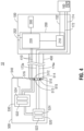
- cooling module 500 includes an input port 510, a pump assembly 520, a controller 530, and a user interface 540.
- Input port 510 enables operable coupling of cable 400 with cooling module 500. More specifically, input port 510 includes an inflow conduit receptacle 512, a return conduit receptacle 514, and one or more electrical receptacles 516.
- Inflow conduit receptacle 512 operably couples inflow conduit 172 with pump assembly 520 upon engagement of cable 400 with cooling module 500
- return conduit receptacle 514 operably couples return conduit 174 with pump assembly 520 upon engagement of cable 400 with cooling module 500
- the electrical receptacles 516 operably couple TAG 200 with controller 530, via wires 410, upon engagement of cable 400 with cooling module 500.
- Inflow and return conduit receptacles 512, 514 each include one or more sensors 513, 515, respectively, associated therewith for sensing the temperature of fluid flowing therethrough, the flow rate of fluid therethrough, and/or the presence of gas bubbles flowing therethrough, as detailed below.
- Fluid reservoir 522 stores fluid to be circulated through conduits 172, 174 and lumen 166 to cool blade 162 of end effector assembly 160 (see FIG. 3 ) after use.
- fluid reservoir 522 may be configured to regulate the temperature of the fluid retained therein.
- an open system may be provided wherein fluid to be circulated is received from an external fluid source (not shown), and fluid returning is output to a drain or return reservoir (not shown).
- Pump 524 is configured as a pull-pump, wherein pump 524 operates to pull fluid through conduits 172, 174 and lumen 166.
- a pull-pump configuration is advantageous in that pressure build-up in push-pump configurations, e.g., due to an obstruction along the fluid flow path, is avoided.
- pump 524 may be configured as a push-pump.
- Pump 524 may be a peristaltic pump, or any other suitable pump.
- controller 530 of cooling module 500 includes a processor 532 and a memory 534 storing instructions for execution by processor 532. Controller 530 is coupled to pump assembly 520, sensors 513, 515, TAG 200 (via wires 410 extending through cable 400), and user interface 540. Controller 530 may be configured to implement the method of FIGS. 10A or 10B so as to instruct pump assembly 520 to turn pump 524 ON or OFF, to thereby initiate or stop blade cooling, based at least upon feedback received from sensors 513, 515, TAG 200, or other received feedback. As detailed below, controller 532 may be configured so as to instruct pump assembly 520 to turn OFF pump 524 where sensor 515 indicates a sufficiently low temperature of fluid returning from return conduit 174.
- the temperature of blade 162 ( FIG. 3 ) of end effector assembly 160 may be extrapolated from the temperature of fluid returning from fluid conduit 174, or the temperature difference between the fluid entering inflow conduit 172 and that returning from return conduit 174, and, accordingly, pump 524 may be turned OFF upon blade 162 reaching a sufficiently cool temperature, e.g., below about 60°C (or other suitable temperature threshold), as indicated by a sufficiently low return fluid temperature or sufficiently small temperature differential.
- a thermocouple 167 ( FIG. 4 ) or other suitable temperature sensor may additionally or alternatively be incorporated into blade 162 (see, for example, thermocouple 2173 ( FIG. 7 )) to enable the sensing of temperature at blade 162.
- Controller 530 may additionally or alternatively instruct pump assembly 520 to turn OFF pump 524 or disable the entire system where sensor 513 and/or sensor 515 indicates an error.
- errors may include, for example, where sensor 513 and/or sensor 515 detects a flow rate through inflow conduit 172 and/or return conduit 174 below a threshold flow rate, and/or where sensor 515 detects gas bubbles, or a gas bubble volume greater than a threshold volume, returning from return conduit 174.
- Reduced flow rate and/or the presence of gas bubbles may be an indication of a blockage or leak within the fluid flow path or damage to one of the conduits 172, 174 and, thus, the circulation of fluid is stopped by turning OFF pump 524 when uch is detected.
- the entire system is disabled, thereby inhibiting further use permanently or until the error or problem is remedied.
- Controller 530 may further be configured, as also detailed below with respect to FIGS. 10A and 10B , to output an appropriate signal to user interface 540 and/or indicator 202 of TAG 200 to alert the user that blade cooling is in effect, e.g., that pump 524 is ON, that an error, e.g., a blockage or leakage, has occurred, and/or that blade 162 ( FIG. 3 ) has been sufficiently cooled and is ready for further use.
- User interface 540 and/or indicator 202 may provide such an alert in the form of audible, visual, and/or tactile output.
- Controller 530 may, additionally or alternatively, as also detailed below with respect to FIGS. 10A and 10B , be configured to communicate with TAG 200 to determine whether endoscopic ultrasonic surgical instrument 100 is in use, e.g., whether activation button 140 is actuated such that ultrasonic energy is being supplied to blade 162 (see FIG. 1 ), and to control pump assembly 520 in accordance therewith. More specifically, controller 530 may instruct pump assembly 520 to turn OFF pump 524 when endoscopic ultrasonic surgical instrument 100 is in use. Once use is complete, pump 524 may be turned ON for a pre-determined time, until blade 162 has been sufficiently cooled, until an error is detected, or until endoscopic ultrasonic surgical instrument 100 is once again put into use.
- Controller 530 may further communicate with TAG 200 to control the cooling system and/or determine whether the cooling system is operating normally based on the frequency of the transducer 210 and/or waveguide 152 ( FIG. 3 ).
- TAG 200 provides, e.g., via wires 410, the frequency of the transducer 210 and/or waveguide 152 ( FIG. 3 ) to the controller 530.
- This frequency information is useful in that it is indicative of the state of the system. More specifically, it has been found that during use, e.g., during tissue treatment, the frequency decreases, while, upon deactivation and release of tissue, the frequency increases.
- controller 530 can determine whether the cooling system is working to effectively cool waveguide 152, or whether cooling is ineffective or inoperable. Such may be used in addition to or in place of temperature sensors.
- the frequency information may be used, in conjunction with the flow rate information from sensors 513, 515, to determine whether cooling is working properly, based upon the flow rates and frequency rate of change, without the need to directly monitor temperature.
- surgical system 20 is similar to surgical system 10 ( FIG. 1 ) and generally includes an endoscopic ultrasonic surgical instrument 1100 and a cooling module 1500. However, rather than being coupled via a cable 400 as with endoscopic ultrasonic surgical instrument 100 and cooling module 500 ( FIG. 1 ), instrument 1100 includes cooling module 1500 disposed thereon, e.g., formed as part of disposable 1102 or releasably mounted thereon.
- Instrument 1100 generally includes a disposable 1102, a transducer and generator assembly (“TAG”) 1200 including a transducer 1210 and a generator 1220, and a battery 1300.
- Disposable 1102 includes a housing 1110, a handle assembly 1120, a rotating assembly 1130, an activation button 1140, an elongated body portion 1150, and an end effector assembly 1160, each of which are similar to the corresponding components of instrument 100 ( FIG. 1 ), detailed above.
- TAG 1200 and battery 1300 are releasably engagable with housing 1110 of disposable 1102 and, when engaged therewith, are disposed in electrical communication with one another such that power and/or control signals can be relayed between TAG 1200 and battery 1300 for operating instrument 1100.
- TAG 1200 and battery 1300 are similar to those detailed above with respect to instrument 100 ( FIG. 1 ), except as otherwise noted below.
- Cooling module 1500 includes input ports 1512, 1514, a pump assembly 1520, and a controller 1530.
- Cooling module 1500 may be permanently mounted on TAG 1200, may be releasably engagable with both TAG 1200 and disposable 1102, or may be permanently mounted on or within disposable 1102.
- Input port 1512 enables operable coupling of pump assembly 1520 with the conduits 1172, 1174 of instrument 1100, while input port 1514 enables communication between controller 1530 and generator 1220, both of which are similar as detailed above with respect to input port 510 ( FIG. 4 ).
- Pump assembly 1520 and controller 1530 are also similar as detailed above, and may be configured to operate in a similar manner as mentioned above and as described in greater detail below.
- Open ultrasonic surgical instrument 2100 is configured to operably coupled to a table-top generator (or other remote generator) (not shown) and a cooling module (similar to cooling module 500). In some embodiments, the generator and cooling module are integrated into a single housing (not shown).
- Open ultrasonic surgical instrument 2100 generally includes two elongated shaft members 2110a, 2110b, an activation button 2140, an elongated body portion 2150, an end effector assembly 2160, a tube assembly 2170, and a transducer assembly 2200.
- each shaft member 2110a, 2110b includes a handle 2111a, 2111b disposed at the proximal end 2112a, 2112b thereof.
- Each handle 2111a, 2111b defines a finger hole 2113a, 2113b therethrough for receiving a finger of the user.
- One of the shaft members, e.g., shaft member 2110a includes a jaw member 2164 of end effector assembly 2160 extending from the distal end 2114a thereof.
- the other shaft member e.g., shaft member 2110b, supports elongated body portion 2150 and transducer assembly 2200 thereon.
- Shaft members 2110a, 2110b are pivotably coupled to one another towards the distal ends 2114a, 2114b, respectively, thereof via a pivot pin 2118.
- Elongated body portion 2150 of shaft member 2110b includes a waveguide 2152 ( FIGS. 8A and 8B ) which extends from transducer assembly 2200 to end effector assembly 2160, and an outer sleeve 2154 surrounding waveguide 2152.
- the distal end of waveguide 2152 extends distally from outer sleeve 2154 and defines a blade 2162 of end effector assembly 2160, while the proximal end of waveguide 2152 is operably coupled to transducer assembly 2200.
- handles 2111a, 2111b may be pivoted relative to one another to thereby pivot jaw member 2164 relative to blade 2162 between an open position, wherein jaw member 2164 is spaced-apart from blade 2162, and a closed position, wherein jaw member 2164 is approximated relative to blade 2162 in juxtaposed alignment therewith for clamping tissue therebetween.
- Transducer assembly 2200 is configured to convert electrical energy provided by the generator (not shown) and supplied via cable 2210, into mechanical energy that is transmitted along waveguide 2152 to blade 2162.
- Transducer assembly 2200 may be permanently affixed to elongated body portion 2150 or may be removable therefrom.
- Activation button 2140 is disposed on one of the shaft members, e.g., shaft member 2110b, and, similarly as detailed above with respect to instrument 100 ( FIG. 1 ), is selectively activatable in a first position and a second position to supply electrical energy to transducer assembly 2200 for operating instrument 2100 in a low-power mode of operation and a high-power mode of operation, respectively.
- elongated body portion 2150 includes waveguide 2152 and outer sleeve 2154.
- the distal end of waveguide 2152 extends distally from outer sleeve 2154 and defines blade 2162.
- Waveguide is secured within outer sleeve 2154 via an O-ring 2156 ( FIGS 8A and 8B ).
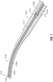
- blade 2162 defines a curved configuration.
- Blade 2162 may be curved in any direction relative to jaw member 2164, for example, such that the distal tip of blade 2162 is curved towards jaw member 2164, away from jaw member 2164, or laterally (in either direction) relative to jaw member 2164.
- Waveguide 2152 and blade 2162 may include any of the features of waveguide 152 and blade 162 (see FIG. 3 ), and vice versa. Further, waveguide 2152 and blade 2162 may be used with instrument 100 ( FIG. 1 ), or any other suitable instrument, and, likewise, waveguide 152 and blade 162 (see FIG. 3 ) may be used with instrument 2100 ( FIG. 6 ), or any other suitable instrument.
- waveguide 2152 defines a lumen 2166 therethrough that extends into blade 2162.
- Lumen 2166 is open at its proximal end, the proximal end of waveguide 2152, and closed at its distal end, the closed distal end of blade 2162.
- Connection between waveguide 2152 and transducer assembly 2200 at the proximal end of waveguide 2152 serves to close off the proximal end of lumen 2166 (see FIG. 8A ).
- Lumen 2166 defines a proximal segment 2167a having the open proximal end and defining a first diameter, and a distal segment 2167b having the closed distal end and defining a second diameter smaller than the first diameter.
- Tube assembly 2170 ( FIG. 6 ) includes inflow and return conduits 2172, 2174, respectively, and a tube splitter 2176 ( FIG. 9 ).
- Conduits 2172, 2174 are arranged such that conduit 2174 is coaxially disposed about conduit 2172.
- Conduits 2172, 2174 enter proximal segment 2167a of lumen 2166, in the above-noted coaxial arrangement, through an opening 2168 disposed in communication with lumen 2166.
- Inflow conduit 2172 extends distally from return conduit 2174 through proximal segment 2167a of lumen 2166 into distal segment 2167b of lumen 2166 to the distal end of blade 2162.
- Inflow conduit 2172 has a smaller diameter than distal segment 2167b of lumen 2166 leaving an annular gap 2169a therebetween to permit the return of fluid to return conduit 2174.
- Return conduit 2174 does not extend into distal segment 2167b of lumen 2166. Rather, a ferrule 2175 is disposed about return conduit 2174 at the distal end of proximal segment 2167b of lumen 2166 so as to seal an annular gap 2169b of lumen 2166 surrounding return conduit 2174.
- inflow conduit 2172 As such, during cooling, fluid is pumped through inflow conduit 2172, exits a distal end of inflow conduit 2172 at the distal end of lumen 2166, and travels proximally back through lumen 2166 within annular gap 2169a, ultimately being received by return conduit 2174.
- Ferrule 2175 inhibits further proximal flow of cooling fluid, e.g., into annular gap 2169b, thus ensuring that the returning fluid enters return conduit 2174.
- tube splitter 2176 of tube assembly 2170 is disposed within one of the shaft members, e.g., shaft member 2110b, of instrument 2100 (see FIG. 6 ).
- Tube splitter 2176 receives the proximal ends of conduits 2172, 2174 which, as noted above, are coaxially disposed relative to one another, and routes the flow of fluid to/from conduits 2172, 2174 and respective connector tubes 2182, 2184.
- Connector tubes 2182, 2184 are coupled with a cooling module (not shown, similar to cooling module 500 ( FIG. 1 )) to enable the inflow and outflow of cooling fluid to/from conduits 2172, 2174, similarly as detailed above with respect to instrument 100 ( FIG. 1 ).
- Tube splitter 2176 generally includes a housing 2190 defining a conduit port 2192, an interior chamber 2194, input and output ports 2196a, 2196b, respectively, and an auxiliary port 2198.
- Conduit port 2192 receives the proximal ends of conduits 2172, 2174 which, as noted above, are disposed in coaxial relation relative to one another.
- Return conduit 2174 is sealingly engaged within conduit port 2192 so as to inhibit the escape of fluid therebetween.
- Return conduit 2174 terminates at interior chamber 2194 and is disposed in fluid communication with interior chamber 2194.
- Inflow conduit 2172 extends through interior chamber 2194 and into input port 2196a, wherein inflow conduit 2172 is sealingly engaged.
- Connector tube 2182 is sealingly engaged about input port 2196a.
- connector tube 2182 fluid flowing through connector tube 2182 is routed into inflow conduit 2172 and, ultimately, through lumen 2166 ( FIG. 7 ) of waveguide 2152 and blade 2162 ( FIG. 7 ).
- Connector tube 2184 is sealingly engaged about output port 2196b, which communicates with chamber 2194.
- fluid flowing through return conduit 2174 ultimately flows into chamber 2194 and, thereafter, out through output port 2196b to connector tube 2184.
- inflow and return conduits 2172, 2174, respectively be reversed, and, thus, that fluid flows in the opposite direction.
- Auxiliary port 2198 communicates with chamber 2194 and includes a stopper 2199 sealingly engaged therein.
- Tube splitter 2176 further includes sensors 2197a, 2197b disposed adjacent input and output portion 2196a, 2196b, respectively, although sensors 2197a 2197b may be positioned at any suitable position on or along instrument 2100 or the components thereof, e.g., the waveguide 2152, blade 2162, inflow and return conduits 2172, 2174, transducer assembly 2200, etc. (see FIGS. 6-8B ).
- Sensors 2197a, 2197b may be configured as thermocouples for sensing temperature and/or may otherwise be configured similar to sensors 513, 515 ( FIG. 4 ), respectively, to, as noted above, sense the temperature of fluid flowing therethrough, the flow rate of fluid therethrough, and/or the presence of gas bubbles flowing therethrough.
- tube splitter 2176 and connector tubes 2182, 2184 may similarly be used in connection with instrument 100, serving to couple cooling module 500 and conduits 172, 174.
- tube splitter 2176 is mounted within housing 110 of disposable 102 so as to receive the proximal ends of conduits 172, 174.
- Connector tubes 2182, 2184 in such a configuration, would extend through cable 400 for coupling with cooling module 500.
- Instrument 100 would otherwise be configured similarly as detailed above and would function in a similar manner as detailed above and described in further detail below.
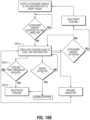
- FIG. 10A a method provided in accordance with the present disclosure, and applicable for use with instrument 100 ( FIG. 1 ), instrument 1100 ( FIG. 5 ), instrument 2100 ( FIG. 6 ), or any other suitable ultrasonic surgical instrument incorporating or configured for use with a cooling system is described.
- the end effector of the instrument is activated so as to supply ultrasonic energy to the end effector thereof to treat, for example, coagulate and/or cut, tissue.
- it is determined whether ultrasonic energy is still being supplied to the end effector Such a determination may be performed, as noted above, by determining whether an activation button is activated. However, other suitable ways of determining whether ultrasonic energy is being supplied to the end effector are also contemplated, e.g., monitoring the output of the battery or the input to or output from the transducer. If it is determined that ultrasonic energy is being supplied, the determination at S902 is repeatedly made, periodically or continuously, until it is determined that ultrasonic energy is no longer being supplied to the end effector.
- the cooling system is activated as indicated in S903, to circulate cooling fluid through the end effector to cool the end effector.
- an indicator S904 is provided to indicate that cooling is ongoing.
- it is determined, at S905, whether the temperature of the end effector is below a threshold temperature.
- the temperature of the end effector may be determined indirectly by sensing the temperature of the fluid output to the end effector and returning therefrom. Such a configuration enables the use of temperature sensors remote from the end effector.
- the threshold temperature in some embodiments, may be about 60°C.
- cooling is deactivated at S906 and an indicator is provided at S904.
- the entire system may be shut down, inhibiting further activation or use, as indicated at S906'.
- An error may include, as noted above, a condition where the flow rate of fluid is below a flow rate threshold, a condition where the fluid includes gas bubbles or a sufficiently high volume of gas bubble, or other suitable error condition.
- the indicator provided in response to an error may be different from the indicator provided during cooling. If no error is detected, cooling continues at S903.
- FIG. 10B another method provided in accordance with the present disclosure, and applicable for use with instrument 100 ( FIG. 1 ), instrument 1100 ( FIG. 5 ), instrument 2100 ( FIG. 6 ), or any other suitable ultrasonic surgical instrument incorporating or configured for use with a cooling system is described.
- the method of FIG. 10B is similar to that of FIG. 10A except that, during cooling, S913, it is determined at S914 whether the time cooling has been activated has reached a threshold time. If the cooling time has reached the threshold time, cooling is deactivated at S915. If the cooling time has not reached the threshold time, cooling continues at S913. Determination of the cooling time may be based upon an uninterrupted duration of cooling, a cumulative amount of cooling since the last energization of the end effector, or in any other suitable manner.
Landscapes
- Health & Medical Sciences (AREA)
- Life Sciences & Earth Sciences (AREA)
- Surgery (AREA)
- Engineering & Computer Science (AREA)
- General Health & Medical Sciences (AREA)
- Veterinary Medicine (AREA)
- Nuclear Medicine, Radiotherapy & Molecular Imaging (AREA)
- Biomedical Technology (AREA)
- Public Health (AREA)
- Animal Behavior & Ethology (AREA)
- Molecular Biology (AREA)
- Medical Informatics (AREA)
- Heart & Thoracic Surgery (AREA)
- Dentistry (AREA)
- Mechanical Engineering (AREA)
- Radiology & Medical Imaging (AREA)
- Orthopedic Medicine & Surgery (AREA)
- Surgical Instruments (AREA)
Abstract
Description
- The present disclosure relates to devices, systems, and methods for cooling a surgical instrument and, in particular, to devices, systems, and methods for cooling a surgical instrument and systems and methods for controlling the same.
- Energy-based tissue treatment is well known in the art. Various types of energy (e.g., electrical, ultrasonic, microwave, cryogenic, thermal, laser, etc.) are applied to tissue to achieve a desired result. Ultrasonic energy, for example, may be delivered to tissue to treat, e.g., coagulate and/or cut, tissue.
- Ultrasonic surgical instruments, for example, typically include a waveguide having a transducer coupled thereto at a proximal end of the waveguide and an end effector disposed at a distal end of the waveguide. The waveguide transmits ultrasonic energy produced by the transducer to the end effector for treating tissue at the end effector. The end effector may include a blade, hook, ball, shears, etc., and/or other features such as one or more jaws for grasping or manipulating tissue. During use, the waveguide and/or end effector of an ultrasonic surgical instrument can reach temperatures greater than 200° C.
- It would therefore be desirable to provide devices, systems, and methods for cooling a surgical instrument and controlling cooling of the same so as to enable cooling of the instrument without negatively impacting the use of the instrument.
- As used herein, the term "distal" refers to the portion that is being described which is further from a user, while the term "proximal" refers to the portion that is being described which is closer to a user. Further, to the extent consistent, any of the aspects described herein may be used in conjunction with any or all of the other aspects described herein.
- Provided in accordance with aspects of the present disclosure is a surgical system including an ultrasonic surgical instrument and a cooling module. The ultrasonic surgical instrument includes a waveguide defining a blade at a distal end thereof and a lumen extending through a portion of the blade, an inflow conduit disposed in communication with the lumen and configured to supply fluid to the lumen, and a return conduit disposed in communication with the lumen and configured to receive fluid from the lumen. The cooling module includes a pump assembly operably coupled to the inflow and return conduits, at least one sensor, and a controller. The pump assembly is configured to pump fluid through the inflow conduit, into the lumen, and back through the return conduit for cooling the blade. The sensor(s) is configured to sense a property of the fluid pumped into the inflow conduit and/or a property of the fluid returned from the return conduit. The controller is configured to control the pump assembly according to the sensed property(s).
- In an aspect of the present disclosure, the sensor(s) is configured to sense a temperature of the fluid returned from the return conduit. In such aspects, the controller may be configured to determine whether the blade is cooled below a threshold temperature based upon the temperature of the fluid returned from the return conduit. The controller may further be configured to turn the pump assembly off when the blade has been cooled below the threshold temperature.
- In another aspect of the present disclosure, the sensor(s) is configured to sense a temperature of the fluid returned from the return conduit and a temperature of the fluid pumped into the inflow conduit. In such aspects, the controller may be configured to determine a differential between the temperature of the fluid pumped into the inflow conduit and the temperature of the fluid returned from the return conduit. The controller may further be configured to turn the pump assembly off when the differential is below a threshold differential.
- In yet another aspect of the present disclosure, the property of the fluid pumped into the inflow conduit and/or the property of the fluid returned from the return conduit indicates whether an error exists in blade cooling.
- In still another aspect of the present disclosure, the sensor(s) is configured to sense a rate of flow of the fluid returned from the return conduit and/or a rate of flow of the fluid pumped into the inflow conduit. In such aspects, the controller is configured to determine whether an error exists based upon the rate(s) of flow.
- In still yet another aspect of the present disclosure, the sensor(s) is configured to sense gas bubbles in the fluid returned from the return conduit and/or gas bubbles in the fluid pumped into the inflow conduit. In such aspects, the controller is configured to determine whether an error exists based upon the presence of gas bubbles.
- In another aspect of the present disclosure, the pump assembly includes a pull pump configured to pull fluid through the return conduit, the lumen, and the inflow conduit.
- In still another aspect of the present disclosure, the ultrasonic surgical instrument further includes an indicator. In such aspects, the controller is configured to activate the indicator during blade cooling.
- In yet another aspect of the present disclosure, the ultrasonic surgical instrument further includes a handle assembly including a movable handle, a jaw member positioned adjacent the blade, and an outer tube extending distally from the handle assembly and including the waveguide extending therethrough. The outer tube operably couples the jaw member and the movable handle such that actuation of the movable handle moves the jaw member relative to the blade from an open position to a clamping position.
- In still another aspect of the present disclosure, the ultrasonic surgical instrument further includes first and second shaft members pivotably coupled to one another. One of the first or second shaft members has a jaw member disposed at a distal end thereof, while the other of the first or second shaft members supports the waveguide thereon. One or both of the shaft members is movable relative to the other between to move the jaw member relative to the blade between an open position and a clamping position.
- A method of cooling an end effector assembly of a surgical instrument provided in accordance with aspects of the present disclosure includes circulating fluid from a cooling module through a lumen defined within a blade of an end effector assembly of a surgical instrument and back to the cooling module, sensing a property of fluid output from the cooling module to the lumen of the blade and/or a property of fluid input to the cooling module from the lumen of the blade, and controlling the circulation of fluid based upon the sensed property(s).
- In an aspect of the present disclosure, the sensed property is a temperature of the fluid input to the cooling module from the lumen of the blade. In such aspects, controlling the circulation of fluid includes stopping the circulation of fluid when the blade is cooled below a threshold temperature as determined by the temperature of the fluid input to the cooling module from the lumen of the blade.
- In another aspect of the present disclosure, the sensed property is a differential between a temperature of the fluid input to the cooling module from the lumen of the blade and a temperature of the fluid output from the cooling module to the lumen of the blade. In such aspects, controlling the circulation of fluid includes stopping the circulation of fluid when the differential is below a threshold differential.
- In yet another aspect of the present disclosure, the sensed property indicates whether an error exists in the circulation of fluid. In such aspects, controlling the circulation of fluid includes stopping the circulation of fluid if an error exists In aspects, activation of the surgical instrument is inhibited when an error exists.
- In still another aspect of the present disclosure, the sensed property is a rate of flow of the fluid output from the cooling module to the lumen of the blade and/or a rate of flow of the fluid input to the cooling module from the lumen of the blade. In such aspects, the rate of flow indicates whether an error exists.
- In still yet another aspect of the present disclosure, the sensed property is a presence of gas bubbles in the fluid output from the cooling module to the lumen of the blade and/or a presence of gas bubbles in the fluid input to the cooling module from the lumen of the blade. In such aspects, the presence of gas bubbles indicates whether an error exists.
- In another aspect of the present disclosure, the method further includes providing an indicator when it is determined that an error exists.
- In still another aspect of the present disclosure, the method further includes providing an indicator when fluid is circulating.
- In yet another aspect of the present disclosure, the method further includes determining whether energy is being supplied to the blade and controlling the circulation of fluid based upon whether energy is being supplied to the blade.
- Various aspects and features of the present disclosure are described hereinbelow with reference to the drawings wherein like numerals designate identical or corresponding elements in each of the several views:
-
FIG. 1 is a perspective view of a surgical system provided in accordance with the present disclosure including an endoscopic ultrasonic surgical instrument, a cooling module, and a cooling system incorporated therein; -
FIG. 2A is an enlarged, perspective view of the area of detail indicated as "2A" inFIG. 1 ; -
FIG. 2B is an enlarged, perspective view of the area of detail indicates as "2B" inFIG. 1 ; -
FIG. 3 is an enlarged, perspective view of the distal end of the surgical instrument ofFIG. 1 ; -
FIG. 4 is a schematic illustration of the surgical system ofFIG. 1 depicting the internal operating components of the cooling system thereof; -
FIG. 5 is an exploded, perspective view of another surgical system provided in accordance with the present disclosure including a handheld endoscopic ultrasonic surgical instrument ultrasonic surgical instrument including an on-board cooling module and having a cooling system incorporated therein; -
FIG. 6 is a side, cross-sectional view of an open ultrasonic surgical instrument provided in accordance with the present disclosure and including a cooling system configured for use therewith; -
FIG. 7 is an enlarged, top, cross-sectional view of the blade of the surgical instrument ofFIG. 6 ; -
FIG. 8A is an enlarged, side, cross-sectional view of a portion of the surgical instrument ofFIG. 6 , illustrating routing of the cooling conduits into and through the waveguide of the surgical instrument; -
FIG. 8B is a greatly enlarged, side, cross-sectional view of a portion of the surgical instrument ofFIG. 6 , illustrating the routing of the cooling conduits through the waveguide of the surgical instrument; -
FIG. 9 is an enlarged, side view illustrating coupling of the cooling conduits of the surgical instrument ofFIG. 6 with a tube splitter of the surgical instrument to enable the supply and return of cooling fluid from the surgical instrument; -
FIG. 10A is a flow diagram depicting a method of cooling a surgical instrument provided in accordance with the present disclosure; and -
FIG. 10B is a flow diagram depicting another method of cooling a surgical instrument provided in accordance with the present disclosure. -
FIG. 1 depicts asurgical system 10 provided in accordance with the aspects and features of the present disclosure.Surgical system 10 generally includes an endoscopic ultrasonicsurgical instrument 100 and abase unit 500 that, together, incorporate a cooling system for cooling ablade 162 of anend effector assembly 160 of endoscopic ultrasonicsurgical instrument 100. Although detailed hereinbelow with respect tosurgical system 10 and, more particularly, endoscopic ultrasonicsurgical instrument 100 andcooling module 500 thereof, the aspects and features of the present disclosure are equally applicable for use with any other suitable surgical system, surgical instrument, and/or cooling module incorporating a cooling system. For example, the aspects and features may be provided for use in connection with a surgical system 20 including an endoscopic ultrasonicsurgical instrument 1100 incorporating acooling module 1500 thereon (seeFIG. 5 ). Further still, another surgical instrument provided in accordance with the present disclosure, open ultrasonic surgical instrument 2100 (FIGS. 6-9 ), may similarly incorporate the aspects and features of the present disclosure. Obviously, different considerations apply to each particular type of system, instrument, and/or unit; however, the aspects and features of the present disclosure are equally applicable and remain generally consistent with respect to any such system, instrument, and/or unit. - Continuing with reference to
FIG. 1 , endoscopic ultrasonicsurgical instrument 100 generally includes a disposable 102, a transducer and generator assembly ("TAG") 200 including atransducer 210 and a generator 220 (FIG. 4 ), abattery 300, and acable 400.Disposable 102 includes ahousing 110, ahandle assembly 120, a rotatingassembly 130, anactivation button 140, anelongated body portion 150, and endeffector assembly 160.TAG 200 andbattery 300 are releasably engagable withhousing 110 of disposable 102 and, when engaged therewith, are disposed in electrical communication with one another such that power and/or control signals can be relayed betweenTAG 200 andbattery 300 for operatinginstrument 100.TAG 200 may further include anindicator 202 disposed thereon, which will be described in greater detail below. -
Elongated body portion 150 of disposable 102 ofinstrument 100 includes awaveguide 152 which extends fromhousing 110 to endeffector assembly 160, anouter tube 154, and an inner tube (not shown). The distal end ofwaveguide 152 extends distally fromouter tube 154 and definesblade 162 ofend effector assembly 160, while the proximal end ofwaveguide 152 is operably coupled toTAG 200.Outer tube 154 is slidably disposed aboutwaveguide 152 and extends betweenhousing 110 and endeffector assembly 160. Rotatingassembly 130 is rotatably mounted onhousing 110 and operably coupled toelongated body portion 150 so as to enable rotation ofelongated body portion 150 and endeffector assembly 160 relative tohousing 110. -
End effector assembly 160 is disposed at a distal end ofelongated body portion 150 and includesblade 162 and ajaw member 164.Jaw member 164 is pivotable relative toblade 162 between an open position, whereinjaw member 164 is spaced-apart fromblade 162, and a closed position, whereinjaw member 164 is approximated relative toblade 162 in juxtaposed alignment therewith for clamping tissue therebetween.Jaw member 164 is operably coupled to the distal end ofouter tube 154 and the proximal end ofouter tube 154 is operably coupled tomovable handle 122 of ahandle assembly 120, such thatjaw member 164 is movable between the open position and the closed position in response to actuation ofmovable handle 122 ofhandle assembly 120 relative to fixedhandle portion 124 thereof. -
Blade 162 is configured to serve as an active or oscillating ultrasonic member that is selectively activatable to ultrasonically treat tissue grasped betweenblade 162 andjaw member 164.TAG 200 is configured to convert electrical energy provided bybattery 300 into mechanical energy that is transmitted alongwaveguide 152 toblade 162. More specifically,TAG 200 is configured to convert the electrical energy provided bybattery 300 into a high voltage alternating current (AC) waveform that drives the transducer (not shown) ofTAG 200.Activation button 140 is disposed onhousing 110 of disposable 102 and is electrically coupled betweenbattery 300 andTAG 200.Activation button 140 is selectively activatable in a first position and a second position to supply electrical energy frombattery 300 toTAG 200 for operatinginstrument 100 in a low-power mode of operation and a high-power mode of operation, respectively. - Referring to
FIGS. 1-3 , cooling inflow and returnconduits module 500, throughhousing 110, and at least partially throughouter tube 154 ofelongated body portion 150 substantially along the length thereof. Proximal ends 173a, 175a of inflow and returnconduits module 500, as detailed below (see alsoFIG. 4 ). - With particular reference to
FIG. 3 , distal ends 173b, 175b of inflow and returnconduits waveguide 152. More specifically, alumen 166 is formed withinwaveguide 152 that extends through a portion ofwaveguide 152 including substantially along the length ofblade 162 of waveguide.Lumen 166 defines a closed distal end.Conduits enter lumen 166 through anopening 168 defined withinwaveguide 152 and disposed in communication withlumen 166. A seal (not shown) disposed withinopening 168 and around inflow and returnconduits Inflow conduit 172 is disposed within and extends distally throughlumen 166. Returnconduit 174 is disposed within the proximal end oflumen 166, although the above-detailed configuration of inflow and returnconduits Inflow conduit 172 has a smaller diameter thanlumen 166 leaving anannular gap 169 therebetween to permit the return of fluid to returnconduit 174. As such, during cooling, fluid, e.g., water, saline, etc., is pumped throughinflow conduit 172, exits a distal end ofinflow conduit 172 at the distal end oflumen 166, and travels proximally back throughlumen 166 withinannular gap 169, ultimately being received byreturn conduit 174 for return to cooling module 500 (FIG. 1 ). Inflow and returnconduits inflow conduit 172 that extends distally throughlumen 166 may be subject to delamination and, as a flow, may block the flow of fluid during use. As such, in embodiments, the portion ofinflow conduit 172 that extends distally throughlumen 166 is formed from stainless steel or other material suitable to withstand high temperatures. Further, in embodiments whereblade 162 is curved, the portion ofinflow conduit 172 that extends distally throughlumen 166 is likewise curved so as not to rub on the interior surface ofblade 162. - Referring to
FIG. 4 ,cooling module 500 includes aninput port 510, apump assembly 520, acontroller 530, and auser interface 540.Input port 510 enables operable coupling ofcable 400 withcooling module 500. More specifically,input port 510 includes aninflow conduit receptacle 512, areturn conduit receptacle 514, and one or moreelectrical receptacles 516.Inflow conduit receptacle 512 operablycouples inflow conduit 172 withpump assembly 520 upon engagement ofcable 400 withcooling module 500, returnconduit receptacle 514 operably couples returnconduit 174 withpump assembly 520 upon engagement ofcable 400 withcooling module 500, and theelectrical receptacles 516operably couple TAG 200 withcontroller 530, viawires 410, upon engagement ofcable 400 withcooling module 500. Inflow and returnconduit receptacles more sensors -
Pump assembly 520 includes afluid reservoir 522 and apump 524 and is coupled betweeninflow conduit 172 and returnconduit 174.Fluid reservoir 522 stores fluid to be circulated throughconduits lumen 166 tocool blade 162 of end effector assembly 160 (seeFIG. 3 ) after use. In some embodiments,fluid reservoir 522 may be configured to regulate the temperature of the fluid retained therein. Further, instead of a closed system utilizingfluid reservoir 522, an open system may be provided wherein fluid to be circulated is received from an external fluid source (not shown), and fluid returning is output to a drain or return reservoir (not shown). -
Pump 524 is configured as a pull-pump, whereinpump 524 operates to pull fluid throughconduits lumen 166. A pull-pump configuration is advantageous in that pressure build-up in push-pump configurations, e.g., due to an obstruction along the fluid flow path, is avoided. However, in some embodiments, pump 524 may be configured as a push-pump. Pump 524 may be a peristaltic pump, or any other suitable pump. - Continuing with reference to
FIG. 4 ,controller 530 ofcooling module 500 includes aprocessor 532 and amemory 534 storing instructions for execution byprocessor 532.Controller 530 is coupled to pumpassembly 520,sensors wires 410 extending through cable 400), anduser interface 540.Controller 530 may be configured to implement the method ofFIGS. 10A or10B so as to instructpump assembly 520 to turnpump 524 ON or OFF, to thereby initiate or stop blade cooling, based at least upon feedback received fromsensors TAG 200, or other received feedback. As detailed below,controller 532 may be configured so as to instructpump assembly 520 to turn OFFpump 524 wheresensor 515 indicates a sufficiently low temperature of fluid returning fromreturn conduit 174. The temperature of blade 162 (FIG. 3 ) ofend effector assembly 160 may be extrapolated from the temperature of fluid returning fromfluid conduit 174, or the temperature difference between the fluidentering inflow conduit 172 and that returning fromreturn conduit 174, and, accordingly, pump 524 may be turned OFF uponblade 162 reaching a sufficiently cool temperature, e.g., below about 60°C (or other suitable temperature threshold), as indicated by a sufficiently low return fluid temperature or sufficiently small temperature differential. As an alternative tosensors input port 510, temperature sensors may be incorporated intopump assembly 520 for similar purposes as noted above. Further, in embodiments, a thermocouple 167 (FIG. 4 ) or other suitable temperature sensor may additionally or alternatively be incorporated into blade 162 (see, for example, thermocouple 2173 (FIG. 7 )) to enable the sensing of temperature atblade 162. -
Controller 530, as also detailed below with respect toFIGS. 10A and10B , may additionally or alternatively instructpump assembly 520 to turn OFFpump 524 or disable the entire system wheresensor 513 and/orsensor 515 indicates an error. Such errors may include, for example, wheresensor 513 and/orsensor 515 detects a flow rate throughinflow conduit 172 and/or returnconduit 174 below a threshold flow rate, and/or wheresensor 515 detects gas bubbles, or a gas bubble volume greater than a threshold volume, returning fromreturn conduit 174. Reduced flow rate and/or the presence of gas bubbles (or a greater volume of gas bubbles) may be an indication of a blockage or leak within the fluid flow path or damage to one of theconduits pump 524 when uch is detected. As noted above, in embodiments, rather than just turning OFFpump 524, the entire system is disabled, thereby inhibiting further use permanently or until the error or problem is remedied. -
Controller 530 may further be configured, as also detailed below with respect toFIGS. 10A and10B , to output an appropriate signal touser interface 540 and/orindicator 202 ofTAG 200 to alert the user that blade cooling is in effect, e.g., that pump 524 is ON, that an error, e.g., a blockage or leakage, has occurred, and/or that blade 162 (FIG. 3 ) has been sufficiently cooled and is ready for further use.User interface 540 and/orindicator 202 may provide such an alert in the form of audible, visual, and/or tactile output. -
Controller 530 may, additionally or alternatively, as also detailed below with respect toFIGS. 10A and10B , be configured to communicate withTAG 200 to determine whether endoscopic ultrasonicsurgical instrument 100 is in use, e.g., whetheractivation button 140 is actuated such that ultrasonic energy is being supplied to blade 162 (seeFIG. 1 ), and to controlpump assembly 520 in accordance therewith. More specifically,controller 530 may instructpump assembly 520 to turn OFFpump 524 when endoscopic ultrasonicsurgical instrument 100 is in use. Once use is complete, pump 524 may be turned ON for a pre-determined time, untilblade 162 has been sufficiently cooled, until an error is detected, or until endoscopic ultrasonicsurgical instrument 100 is once again put into use. -
Controller 530 may further communicate withTAG 200 to control the cooling system and/or determine whether the cooling system is operating normally based on the frequency of thetransducer 210 and/or waveguide 152 (FIG. 3 ). Thus,TAG 200 provides, e.g., viawires 410, the frequency of thetransducer 210 and/or waveguide 152 (FIG. 3 ) to thecontroller 530. This frequency information is useful in that it is indicative of the state of the system. More specifically, it has been found that during use, e.g., during tissue treatment, the frequency decreases, while, upon deactivation and release of tissue, the frequency increases. It has further been found that, ifwaveguide 152 is cooled shortly after deactivation and release of tissue, the frequency increases at a significantly greater rate as compared to anun-cooled waveguide 152. Thus by monitoring the rate of change in frequency, e.g., by monitoring deviation of the rate of change relative to a threshold value or threshold range,controller 530 can determine whether the cooling system is working to effectivelycool waveguide 152, or whether cooling is ineffective or inoperable. Such may be used in addition to or in place of temperature sensors. For example, the frequency information may be used, in conjunction with the flow rate information fromsensors - Turning now to
FIG. 5 , surgical system 20 is similar to surgical system 10 (FIG. 1 ) and generally includes an endoscopic ultrasonicsurgical instrument 1100 and acooling module 1500. However, rather than being coupled via acable 400 as with endoscopic ultrasonicsurgical instrument 100 and cooling module 500 (FIG. 1 ),instrument 1100 includescooling module 1500 disposed thereon, e.g., formed as part of disposable 1102 or releasably mounted thereon. -
Instrument 1100 generally includes a disposable 1102, a transducer and generator assembly ("TAG") 1200 including atransducer 1210 and agenerator 1220, and abattery 1300. Disposable 1102 includes ahousing 1110, ahandle assembly 1120, a rotatingassembly 1130, anactivation button 1140, anelongated body portion 1150, and anend effector assembly 1160, each of which are similar to the corresponding components of instrument 100 (FIG. 1 ), detailed above.TAG 1200 andbattery 1300 are releasably engagable withhousing 1110 of disposable 1102 and, when engaged therewith, are disposed in electrical communication with one another such that power and/or control signals can be relayed betweenTAG 1200 andbattery 1300 for operatinginstrument 1100.TAG 1200 andbattery 1300 are similar to those detailed above with respect to instrument 100 (FIG. 1 ), except as otherwise noted below. -
Cooling module 1500, similar as with cooling module 500 (FIG. 4 ), includesinput ports pump assembly 1520, and acontroller 1530.Cooling module 1500 may be permanently mounted onTAG 1200, may be releasably engagable with bothTAG 1200 and disposable 1102, or may be permanently mounted on or within disposable 1102.Input port 1512 enables operable coupling ofpump assembly 1520 with theconduits instrument 1100, whileinput port 1514 enables communication betweencontroller 1530 andgenerator 1220, both of which are similar as detailed above with respect to input port 510 (FIG. 4 ).Pump assembly 1520 andcontroller 1530 are also similar as detailed above, and may be configured to operate in a similar manner as mentioned above and as described in greater detail below. - Turning now to
FIGS. 6-9 , another instrument provided in accordance with the present disclosure, an open ultrasonicsurgical instrument 2100, is detailed. Open ultrasonicsurgical instrument 2100 is configured to operably coupled to a table-top generator (or other remote generator) (not shown) and a cooling module (similar to cooling module 500). In some embodiments, the generator and cooling module are integrated into a single housing (not shown). Open ultrasonicsurgical instrument 2100 generally includes twoelongated shaft members activation button 2140, anelongated body portion 2150, anend effector assembly 2160, atube assembly 2170, and atransducer assembly 2200. - Referring to
FIG. 6 , eachshaft member handle proximal end handle finger hole shaft member 2110a, includes ajaw member 2164 ofend effector assembly 2160 extending from thedistal end 2114a thereof. The other shaft member, e.g.,shaft member 2110b, supports elongatedbody portion 2150 andtransducer assembly 2200 thereon.Shaft members distal ends pivot pin 2118. -
Elongated body portion 2150 ofshaft member 2110b includes a waveguide 2152 (FIGS. 8A and 8B ) which extends fromtransducer assembly 2200 to endeffector assembly 2160, and anouter sleeve 2154 surroundingwaveguide 2152. The distal end ofwaveguide 2152 extends distally fromouter sleeve 2154 and defines ablade 2162 ofend effector assembly 2160, while the proximal end ofwaveguide 2152 is operably coupled totransducer assembly 2200. Due to the pivotable coupling ofshaft members distal ends jaw member 2164 relative toblade 2162 between an open position, whereinjaw member 2164 is spaced-apart fromblade 2162, and a closed position, whereinjaw member 2164 is approximated relative toblade 2162 in juxtaposed alignment therewith for clamping tissue therebetween. -
Transducer assembly 2200 is configured to convert electrical energy provided by the generator (not shown) and supplied viacable 2210, into mechanical energy that is transmitted alongwaveguide 2152 toblade 2162.Transducer assembly 2200 may be permanently affixed toelongated body portion 2150 or may be removable therefrom.Activation button 2140 is disposed on one of the shaft members, e.g.,shaft member 2110b, and, similarly as detailed above with respect to instrument 100 (FIG. 1 ), is selectively activatable in a first position and a second position to supply electrical energy totransducer assembly 2200 for operatinginstrument 2100 in a low-power mode of operation and a high-power mode of operation, respectively. - With reference to
FIGS. 7 and8A-8B ,elongated body portion 2150 is described in greater detail. As noted above,elongated body portion 2150 includeswaveguide 2152 andouter sleeve 2154. The distal end ofwaveguide 2152 extends distally fromouter sleeve 2154 and definesblade 2162. Waveguide is secured withinouter sleeve 2154 via an O-ring 2156 (FIGS 8A and 8B ). As shown inFIG. 7 ,blade 2162 defines a curved configuration.Blade 2162 may be curved in any direction relative tojaw member 2164, for example, such that the distal tip ofblade 2162 is curved towardsjaw member 2164, away fromjaw member 2164, or laterally (in either direction) relative tojaw member 2164.Waveguide 2152 andblade 2162 may include any of the features ofwaveguide 152 and blade 162 (seeFIG. 3 ), and vice versa. Further,waveguide 2152 andblade 2162 may be used with instrument 100 (FIG. 1 ), or any other suitable instrument, and, likewise,waveguide 152 and blade 162 (seeFIG. 3 ) may be used with instrument 2100 (FIG. 6 ), or any other suitable instrument. - Referring again to
FIGS. 7 and8A-8B ,waveguide 2152 defines alumen 2166 therethrough that extends intoblade 2162.Lumen 2166 is open at its proximal end, the proximal end ofwaveguide 2152, and closed at its distal end, the closed distal end ofblade 2162. Connection betweenwaveguide 2152 andtransducer assembly 2200 at the proximal end ofwaveguide 2152 serves to close off the proximal end of lumen 2166 (seeFIG. 8A ).Lumen 2166 defines aproximal segment 2167a having the open proximal end and defining a first diameter, and adistal segment 2167b having the closed distal end and defining a second diameter smaller than the first diameter. - Tube assembly 2170 (
FIG. 6 ) includes inflow and returnconduits FIG. 9 ).Conduits conduit 2174 is coaxially disposed aboutconduit 2172.Conduits proximal segment 2167a oflumen 2166, in the above-noted coaxial arrangement, through anopening 2168 disposed in communication withlumen 2166.Inflow conduit 2172 extends distally fromreturn conduit 2174 throughproximal segment 2167a oflumen 2166 intodistal segment 2167b oflumen 2166 to the distal end ofblade 2162.Inflow conduit 2172 has a smaller diameter thandistal segment 2167b oflumen 2166 leaving anannular gap 2169a therebetween to permit the return of fluid to returnconduit 2174.Return conduit 2174 does not extend intodistal segment 2167b oflumen 2166. Rather, aferrule 2175 is disposed aboutreturn conduit 2174 at the distal end ofproximal segment 2167b oflumen 2166 so as to seal anannular gap 2169b oflumen 2166 surroundingreturn conduit 2174. As such, during cooling, fluid is pumped throughinflow conduit 2172, exits a distal end ofinflow conduit 2172 at the distal end oflumen 2166, and travels proximally back throughlumen 2166 withinannular gap 2169a, ultimately being received byreturn conduit 2174.Ferrule 2175 inhibits further proximal flow of cooling fluid, e.g., intoannular gap 2169b, thus ensuring that the returning fluid enters returnconduit 2174. - Referring to
FIG. 9 ,tube splitter 2176 oftube assembly 2170 is disposed within one of the shaft members, e.g.,shaft member 2110b, of instrument 2100 (seeFIG. 6 ).Tube splitter 2176 receives the proximal ends ofconduits conduits respective connector tubes Connector tubes FIG. 1 )) to enable the inflow and outflow of cooling fluid to/fromconduits FIG. 1 ). -
Tube splitter 2176 generally includes ahousing 2190 defining aconduit port 2192, aninterior chamber 2194, input andoutput ports auxiliary port 2198.Conduit port 2192 receives the proximal ends ofconduits Return conduit 2174 is sealingly engaged withinconduit port 2192 so as to inhibit the escape of fluid therebetween.Return conduit 2174 terminates atinterior chamber 2194 and is disposed in fluid communication withinterior chamber 2194.Inflow conduit 2172 extends throughinterior chamber 2194 and intoinput port 2196a, whereininflow conduit 2172 is sealingly engaged.Connector tube 2182 is sealingly engaged aboutinput port 2196a. Thus, fluid flowing throughconnector tube 2182 is routed intoinflow conduit 2172 and, ultimately, through lumen 2166 (FIG. 7 ) ofwaveguide 2152 and blade 2162 (FIG. 7 ).Connector tube 2184 is sealingly engaged aboutoutput port 2196b, which communicates withchamber 2194. As such, fluid flowing throughreturn conduit 2174 ultimately flows intochamber 2194 and, thereafter, out throughoutput port 2196b toconnector tube 2184. However, it is also contemplated that inflow and returnconduits Auxiliary port 2198 communicates withchamber 2194 and includes astopper 2199 sealingly engaged therein. -
Tube splitter 2176 further includessensors output portion sensors 2197a 2197b may be positioned at any suitable position on or alonginstrument 2100 or the components thereof, e.g., thewaveguide 2152,blade 2162, inflow and returnconduits transducer assembly 2200, etc. (seeFIGS. 6-8B ).Sensors sensors 513, 515 (FIG. 4 ), respectively, to, as noted above, sense the temperature of fluid flowing therethrough, the flow rate of fluid therethrough, and/or the presence of gas bubbles flowing therethrough. - Referring to
FIGS. 1 and9 , although detailed above with respect to instrument 2100 (FIG. 6 ),tube splitter 2176 andconnector tubes instrument 100, serving to couple coolingmodule 500 andconduits tube splitter 2176 is mounted withinhousing 110 of disposable 102 so as to receive the proximal ends ofconduits Connector tubes cable 400 for coupling withcooling module 500.Instrument 100 would otherwise be configured similarly as detailed above and would function in a similar manner as detailed above and described in further detail below. - Turning now to
FIG. 10A , a method provided in accordance with the present disclosure, and applicable for use with instrument 100 (FIG. 1 ), instrument 1100 (FIG. 5 ), instrument 2100 (FIG. 6 ), or any other suitable ultrasonic surgical instrument incorporating or configured for use with a cooling system is described. - Initially, at S901, the end effector of the instrument is activated so as to supply ultrasonic energy to the end effector thereof to treat, for example, coagulate and/or cut, tissue. At S902 it is determined whether ultrasonic energy is still being supplied to the end effector. Such a determination may be performed, as noted above, by determining whether an activation button is activated. However, other suitable ways of determining whether ultrasonic energy is being supplied to the end effector are also contemplated, e.g., monitoring the output of the battery or the input to or output from the transducer. If it is determined that ultrasonic energy is being supplied, the determination at S902 is repeatedly made, periodically or continuously, until it is determined that ultrasonic energy is no longer being supplied to the end effector.
- Once it is determined that ultrasonic energy is no longer being supplied to the end effector, the cooling system is activated as indicated in S903, to circulate cooling fluid through the end effector to cool the end effector. Likewise, an indicator S904 is provided to indicate that cooling is ongoing. During cooling, it is determined, at S905, whether the temperature of the end effector is below a threshold temperature. As noted above with respect to instrument 100 (
FIG. 1 ), the temperature of the end effector may be determined indirectly by sensing the temperature of the fluid output to the end effector and returning therefrom. Such a configuration enables the use of temperature sensors remote from the end effector. - If the temperature of the end effector is determined to be above the threshold temperature, cooling continues at S903 and the temperature is continuously or periodically determined at S905. At the same time, an indicator, as indicated in S904, is provided to alert the user that cooling is still ongoing. Once the temperature of the end effector assembly is below the threshold temperature, as indicated in S906, cooling is deactivated and the indicator is removed. The threshold temperature, in some embodiments, may be about 60°C.
- Referring to S907, during cooling, if an error is detected, cooling is deactivated at S906 and an indicator is provided at S904. Alternatively, the entire system may be shut down, inhibiting further activation or use, as indicated at S906'. An error may include, as noted above, a condition where the flow rate of fluid is below a flow rate threshold, a condition where the fluid includes gas bubbles or a sufficiently high volume of gas bubble, or other suitable error condition. The indicator provided in response to an error may be different from the indicator provided during cooling. If no error is detected, cooling continues at S903.
- Turning to S908, during cooling, it is determined whether the supply of ultrasonic energy to the end effector has been activated. If so, cooling is deactivated at S909 and the method returns to S901. If the supplying of ultrasonic energy to the end effector has not been activated, the method returns to S903 and cooling is continued until the temperature of the end effector is below the threshold temperature, an error is detected, or the supply of ultrasonic energy to the end effector is activated.
- Referring to
FIG. 10B , another method provided in accordance with the present disclosure, and applicable for use with instrument 100 (FIG. 1 ), instrument 1100 (FIG. 5 ), instrument 2100 (FIG. 6 ), or any other suitable ultrasonic surgical instrument incorporating or configured for use with a cooling system is described. - The method of
FIG. 10B is similar to that ofFIG. 10A except that, during cooling, S913, it is determined at S914 whether the time cooling has been activated has reached a threshold time. If the cooling time has reached the threshold time, cooling is deactivated at S915. If the cooling time has not reached the threshold time, cooling continues at S913. Determination of the cooling time may be based upon an uninterrupted duration of cooling, a cumulative amount of cooling since the last energization of the end effector, or in any other suitable manner. - While several embodiments of the disclosure have been shown in the drawings and described hereinabove, it is not intended that the disclosure be limited thereto, as it is intended that the disclosure be as broad in scope as the art will allow and that the specification be read likewise. Therefore, the above description should not be construed as limiting, but merely as exemplifications of particular embodiments. Those skilled in the art will envision other modifications within the scope and spirit of the claims appended hereto.
- The invention may be described by reference to the following numbered paragraphs:-
- 1. A surgical system, comprising:
- an ultrasonic surgical instrument, including:
- a waveguide defining a blade at a distal end thereof and a lumen extending through a portion of the blade,
- an inflow conduit disposed in communication with the lumen, the inflow conduit configured to supply fluid to the lumen, and
- a return conduit disposed in communication with the lumen, the return conduit configured to receive fluid from the lumen; and
- a cooling module, including:
- a pump assembly operably coupled to the inflow and return conduits, the pump assembly configured to pump fluid through the inflow conduit, into the lumen, and back through the return conduit for cooling the blade,
- at least one sensor configured to sense at least one of a property of the fluid pumped into the inflow conduit or a property of the fluid returned from the return conduit, and
- a controller configured to control the pump assembly according to the at least one sensed property.
- an ultrasonic surgical instrument, including:
- 2. The surgical system according to paragraph 1, wherein the at least one sensor is configured to sense a temperature of the fluid returned from the return conduit.
- 3. The surgical system according to paragraph 2, wherein the controller is configured to determine whether the blade has been cooled below a threshold temperature based upon the temperature of the fluid returned from the return conduit and to turn the pump assembly off when the blade is determined to have been cooled below the threshold temperature.
- 4. The surgical system according to paragraph 2, wherein the at least one sensor is further configured to sense a temperature of the fluid pumped into the inflow conduit, wherein the controller is configured to determine a differential between the temperature of the fluid pumped into the inflow conduit and the temperature of the fluid returned from the return conduit and to turn the pump assembly off when the differential is below a threshold differential.
- 5. The surgical system according to paragraph 1, wherein the at least one of the property of the fluid pumped into the inflow conduit or the property of the fluid returned from the return conduit indicates whether an error exists.
- 6. The surgical system according to paragraph 5, wherein the at least one sensor is configured to sense at least one of a rate of flow of the fluid returned from the return conduit or a rate of flow of the fluid pumped into the inflow conduit, and wherein the controller is configured to determine whether an error exists based upon the at least one rate of flow.
- 7. The surgical system according to paragraph 5, wherein the at least one sensor is configured to sense gas bubbles in the fluid returned from the return conduit or gas bubbles in the fluid pumped into the inflow conduit, and wherein the controller is configured to determine whether an error exists based upon the presence of gas bubbles.
- 8. The surgical system according to paragraph 1, wherein the pump assembly includes a pull pump configured to pull fluid through the return conduit, the lumen, and the inflow conduit.
- 9. The surgical system according to paragraph 1, wherein the ultrasonic surgical instrument further includes an indicator, and wherein the controller is configured to activate the indicator during blade cooling.
- 10. The surgical system according to paragraph 1, wherein the ultrasonic surgical instrument further includes:
- a handle assembly including a movable handle,
- a jaw member positioned adjacent the blade, and
- an outer tube extending distally from the handle assembly and including the waveguide extending therethrough, the outer tube operably coupling the jaw member and the movable handle such that actuation of the movable handle moves the jaw member relative to the blade from an open position to a clamping position.
- 11. The surgical system according to paragraph 1, wherein the ultrasonic surgical instrument further includes first and second shaft members pivotably coupled to one another, one of the first or second shaft members having a jaw member disposed at a distal end thereof, the other of the first or second shaft members supporting the waveguide thereon, at least one of the first or second shaft members movable relative to the other to move the jaw member relative to the blade between an open position and a clamping position.
- 12. A method of cooling an end effector assembly of a surgical instrument, comprising:
- circulating fluid from a cooling module through a lumen defined within a blade of an end effector assembly of a surgical instrument and back to the cooling module;
- sensing at least one of a property of fluid output from the cooling module to the lumen of the blade or a property of fluid input to the cooling module from the lumen of the blade; and
- controlling the circulation of fluid based upon the at least one sensed property.
- 13. The method according to paragraph 12, wherein the at least one sensed property is a temperature of the fluid input to the cooling module from the lumen of the blade, and wherein controlling the circulation of fluid includes stopping the circulation of fluid when the blade is sufficiently cool as determined by the temperature of the fluid input to the cooling module from the lumen of the blade.
- 14. The method according to paragraph 12, wherein the at least one sensed property is a differential between a temperature of the fluid input to the cooling module from the lumen of the blade and a temperature of the fluid output from the cooling module to the lumen of the blade, and wherein controlling the circulation of fluid includes stopping the circulation of fluid when the blade is sufficiently cool as determined by the differential.
- 15. The method according to paragraph 12, wherein the at least one sensed property indicates whether an error exists, and wherein controlling the circulation of fluid includes stopping the circulation of fluid if an error exists.
- 16. The method according to paragraph 15, wherein the at least one sensed property is at least one of a rate of flow of the fluid output from the cooling module to the lumen of the blade or a rate of flow of the fluid input to the cooling module from the lumen of the blade, and wherein the at least one rate of flow indicates whether an error exists.
- 17. The method according to paragraph 15, wherein the at least one sensed property is at least one of a presence of gas bubbles in the fluid output from the cooling module to the lumen of the blade or a presence of gas bubbles in the fluid input to the cooling module from the lumen of the blade, and wherein the at least one presence of gas bubbles indicates whether an error exists.
- 18. The method according to paragraph 15, further comprising providing an indicator when it is determined that an error exists.
- 19. The method according to paragraph 12, further comprising providing an indicator when fluid is circulating.
- 20. The method according to paragraph 12, further comprising:
- determining whether energy is being supplied to the blade; and
- controlling the circulation of fluid based upon whether energy is being supplied to the blade.
Claims (14)
- A surgical system, comprising:an ultrasonic surgical instrument, including:a waveguide defining a blade at a distal end thereof and a lumen extending through a portion of the blade,an inflow conduit disposed in communication with the lumen, the inflow conduit configured to supply fluid to the lumen, anda return conduit disposed in communication with the lumen, the return conduit configured to receive fluid from the lumen; anda cooling module, including:a pump assembly operably coupled to the inflow and return conduits, the pump assembly configured to pump fluid through the inflow conduit, into the lumen, and back through the return conduit for cooling the blade,at least one sensor configured to sense at least one of a property of the fluid pumped into the inflow conduit or a property of the fluid returned from the return conduit, anda controller configured to control the pump assembly according to the at least one sensed propertywherein the at least one of the property of the fluid pumped into the inflow conduit or the property of the fluid returned from the return conduit indicates whether an error existswherein the at least one sensor is configured to sense at least one of a rate of flow of the fluid returned from the return conduit or a rate of flow of the fluid pumped into the inflow conduit, and wherein the controller is configured to determine whether an error exists based upon the at least one rate of flow orwherein the at least one sensor is configured to sense gas bubbles in the fluid returned from the return conduit or gas bubbles in the fluid pumped into the inflow conduit, and wherein the controller is configured to determine whether an error exists based upon the presence of gas bubbles.
- The surgical system according to claim 1, wherein the at least one sensor is configured to sense a temperature of the fluid returned from the return conduit.
- The surgical system according to claim 2, wherein the controller is configured to determine whether the blade has been cooled below a threshold temperature based upon the temperature of the fluid returned from the return conduit and to turn the pump assembly off when the blade is determined to have been cooled below the threshold temperature.
- The surgical system according to claim 2, wherein the at least one sensor is further configured to sense a temperature of the fluid pumped into the inflow conduit, wherein the controller is configured to determine a differential between the temperature of the fluid pumped into the inflow conduit and the temperature of the fluid returned from the return conduit and to turn the pump assembly off when the differential is below a threshold differential.
- The surgical system according to claim 1, wherein the pump assembly includes a pull pump configured to pull fluid through the return conduit, the lumen, and the inflow conduit.
- The surgical system according to claim 1, wherein the ultrasonic surgical instrument further includes an indicator, and wherein the controller is configured to activate the indicator during blade cooling.
- The surgical system according to claim 1, wherein the ultrasonic surgical instrument further includes:a handle assembly including a movable handle,a jaw member positioned adjacent the blade, andan outer tube extending distally from the handle assembly and including the waveguide extending therethrough, the outer tube operably coupling the jaw member and the movable handle such that actuation of the movable handle moves the jaw member relative to the blade from an open position to a clamping position.
- The surgical system according to claim 1, wherein the ultrasonic surgical instrument further includes first and second shaft members pivotably coupled to one another, one of the first or second shaft members having a jaw member disposed at a distal end thereof, the other of the first or second shaft members supporting the waveguide thereon, at least one of the first or second shaft members movable relative to the other to move the jaw member relative to the blade between an open position and a clamping position.
- A method of cooling an end effector assembly of a surgical instrument, comprising:circulating fluid from a cooling module through a lumen defined within a blade of an end effector assembly of a surgical instrument and back to the cooling module;sensing at least one of a property of fluid output from the cooling module to the lumen of the blade or a property of fluid input to the cooling module from the lumen of the blade; andcontrolling the circulation of fluid based upon the at least one sensed propertywherein the at least one sensed property indicates whether an error exists, and wherein controlling the circulation of fluid includes stopping the circulation of fluid if an error existswherein the at least one sensed property is at least one of a rate of flow of the fluid output from the cooling module to the lumen of the blade or a rate of flow of the fluid input to the cooling module from the lumen of the blade, and wherein the at least one rate of flow indicates whether an error exists orwherein the at least one sensed property is at least one of a presence of gas bubbles in the fluid output from the cooling module to the lumen of the blade or a presence of gas bubbles in the fluid input to the cooling module from the lumen of the blade, and wherein the at least one presence of gas bubbles indicates whether an error exists.
- The method according to claim 12, wherein the at least one sensed property is a temperature of the fluid input to the cooling module from the lumen of the blade, and wherein controlling the circulation of fluid includes stopping the circulation of fluid when the blade is sufficiently cool as determined by the temperature of the fluid input to the cooling module from the lumen of the blade.
- The method according to claim 10, wherein the at least one sensed property is a differential between a temperature of the fluid input to the cooling module from the lumen of the blade and a temperature of the fluid output from the cooling module to the lumen of the blade, and wherein controlling the circulation of fluid includes stopping the circulation of fluid when the blade is sufficiently cool as determined by the differential.
- The method according to claim 9, further comprising providing an indicator when it is determined that an error exists.
- The method according to claim 9, further comprising providing an indicator when fluid is circulating.
- The method according to claim 9, further comprising:determining whether energy is being supplied to the blade; andcontrolling the circulation of fluid based upon whether energy is being supplied to the blade.
Applications Claiming Priority (4)
| Application Number | Priority Date | Filing Date | Title |
|---|---|---|---|
| US201662314650P | 2016-03-29 | 2016-03-29 | |
| US201662314633P | 2016-03-29 | 2016-03-29 | |
| US15/462,812 US10456156B2 (en) | 2016-03-29 | 2017-03-18 | Devices, systems, and methods for cooling a surgical instrument |
| EP17163246.6A EP3225200B1 (en) | 2016-03-29 | 2017-03-28 | Devices, systems, and methods for cooling a surgical instrument |
Related Parent Applications (2)
| Application Number | Title | Priority Date | Filing Date |
|---|---|---|---|
| EP17163246.6A Division EP3225200B1 (en) | 2016-03-29 | 2017-03-28 | Devices, systems, and methods for cooling a surgical instrument |
| EP17163246.6A Division-Into EP3225200B1 (en) | 2016-03-29 | 2017-03-28 | Devices, systems, and methods for cooling a surgical instrument |
Publications (1)
| Publication Number | Publication Date |
|---|---|
| EP4223238A1 true EP4223238A1 (en) | 2023-08-09 |
Family
ID=58454895
Family Applications (2)
| Application Number | Title | Priority Date | Filing Date |
|---|---|---|---|
| EP23163972.5A Withdrawn EP4223238A1 (en) | 2016-03-29 | 2017-03-28 | Devices, systems, and methods for cooling a surgical instrument |
| EP17163246.6A Active EP3225200B1 (en) | 2016-03-29 | 2017-03-28 | Devices, systems, and methods for cooling a surgical instrument |
Family Applications After (1)
| Application Number | Title | Priority Date | Filing Date |
|---|---|---|---|
| EP17163246.6A Active EP3225200B1 (en) | 2016-03-29 | 2017-03-28 | Devices, systems, and methods for cooling a surgical instrument |
Country Status (3)
| Country | Link |
|---|---|
| US (1) | US10456156B2 (en) |
| EP (2) | EP4223238A1 (en) |
| JP (1) | JP6434074B2 (en) |
Families Citing this family (8)
| Publication number | Priority date | Publication date | Assignee | Title |
|---|---|---|---|---|
| US10342566B2 (en) * | 2016-03-29 | 2019-07-09 | Covidien Lp | Devices, systems, and methods for cooling a surgical instrument |
| US10881424B2 (en) * | 2018-02-13 | 2021-01-05 | Covidien Lp | Removable fluid reservoir and ultrasonic surgical instrument including the same |
| EP3911254B1 (en) | 2019-01-15 | 2023-11-01 | Stryker European Operations Limited | Ultrasonic surgical irrigation sleeve and related assemblies |
| US11844563B2 (en) | 2019-11-19 | 2023-12-19 | Covidien Lp | Energy-based surgical instruments incorporating cooling features |
| US20210393308A1 (en) * | 2020-06-18 | 2021-12-23 | Covidien Lp | Devices for cooling a surgical instrument |
| US12414793B2 (en) | 2021-01-06 | 2025-09-16 | Covidien Lp | Devices, systems, and methods of manufacturing fluid-cooled ultrasonic surgical instruments |
| MX2024005971A (en) | 2021-11-19 | 2024-07-19 | Avent Inc | SYSTEMS, DEVICES AND METHODS RELATING TO A RADIOFREQUENCY TREATMENT PROCEDURE WITH COOLING. |
| EP4465908A1 (en) | 2022-01-21 | 2024-11-27 | Covidien LP | Fluid-cooled ultrasonic surgical instruments |
Citations (6)
| Publication number | Priority date | Publication date | Assignee | Title |
|---|---|---|---|---|
| US5326342A (en) * | 1991-01-11 | 1994-07-05 | Baxter International Inc. | Ultrasonic angioplasty device incorporating all ultrasound transmission member made at least partially from a superlastic metal alloy |
| US20110077638A1 (en) * | 2009-09-29 | 2011-03-31 | Vivant Medical, Inc. | Flow Rate Monitor For Fluid Cooled Microwave Ablation Probe |
| US20140005521A1 (en) * | 2010-11-18 | 2014-01-02 | Koninklijke Philips Electronics N.V. | Catheter comprising capacitive micromachined ultrasonic transducers with an adjustable focus |
| US20150073457A1 (en) * | 2013-09-11 | 2015-03-12 | Covidien Lp | Ultrasonic surgical instrument with cooling system |
| US20150164586A1 (en) * | 2010-02-19 | 2015-06-18 | Covidien Lp | Ablation devices with dual operating frequencies, systems including same, and methods of adusting ablation volume using same |
| WO2015148541A1 (en) * | 2014-03-24 | 2015-10-01 | Fractyl Laboratories, Inc. | Injectate delivery devices, systems and methods |
Family Cites Families (108)
| Publication number | Priority date | Publication date | Assignee | Title |
|---|---|---|---|---|
| NL145136C (en) | 1967-07-25 | 1900-01-01 | ||
| US4016882A (en) | 1975-03-05 | 1977-04-12 | Cavitron Corporation | Neurosonic aspirator and method |
| US4223676A (en) | 1977-12-19 | 1980-09-23 | Cavitron Corporation | Ultrasonic aspirator |
| WO1984003828A1 (en) | 1983-04-04 | 1984-10-11 | Sumitomo Bakelite Co | Ultrasonic oscillator |
| US4660573A (en) | 1985-05-08 | 1987-04-28 | Fibra-Sonics, Inc. | Ultrasonic lithotriptor probe |
| JPS6266848A (en) | 1985-09-20 | 1987-03-26 | 住友ベークライト株式会社 | Surgical operation appliance |
| SU1417868A1 (en) | 1985-11-20 | 1988-08-23 | Томский государственный медицинский институт | Cryoultrasonic scalpel |
| US4681561A (en) | 1986-01-24 | 1987-07-21 | Coopervision, Inc. | Ultrasonic decoupling sleeve |
| JPH0767460B2 (en) * | 1986-03-28 | 1995-07-26 | オリンパス光学工業株式会社 | Ultrasonic treatment device |
| SU1563684A1 (en) | 1986-05-26 | 1990-05-15 | Томский государственный медицинский институт | Cryosurgical scalpel |
| JPS63122923A (en) | 1986-11-13 | 1988-05-26 | Agency Of Ind Science & Technol | Ultrasonic thermometric apparatus |
| JPH01151452A (en) | 1987-12-09 | 1989-06-14 | Olympus Optical Co Ltd | Ultrasonic suction apparatus |
| US5163433A (en) | 1989-11-01 | 1992-11-17 | Olympus Optical Co., Ltd. | Ultrasound type treatment apparatus |
| US5076276A (en) | 1989-11-01 | 1991-12-31 | Olympus Optical Co., Ltd. | Ultrasound type treatment apparatus |
| US5391144A (en) | 1990-02-02 | 1995-02-21 | Olympus Optical Co., Ltd. | Ultrasonic treatment apparatus |
| US5211625A (en) | 1990-03-20 | 1993-05-18 | Olympus Optical Co., Ltd. | Ultrasonic treatment apparatus |
| CA2042006C (en) | 1990-05-11 | 1995-08-29 | Morito Idemoto | Surgical ultrasonic horn |
| DE69024805T2 (en) | 1990-05-17 | 1996-05-23 | Sumitomo Bakelite Co | SURGICAL INSTRUMENT |
| JPH04329940A (en) | 1991-01-25 | 1992-11-18 | Olympus Optical Co Ltd | Ultrasonic suction apparatus |
| IT1249059B (en) | 1991-05-22 | 1995-02-11 | Rosa Antonio | ULTRASONIC DISSECTOR-DISCONNECTOR OF ATEROSCLEROTIC PLATES |
| US5221282A (en) | 1991-05-29 | 1993-06-22 | Sonokinetics Group | Tapered tip ultrasonic aspirator |
| US5358505A (en) | 1991-05-29 | 1994-10-25 | Sonokinetics, Inc. | Tapered tip ultrasonic aspiration method |
| US6770071B2 (en) | 1995-06-07 | 2004-08-03 | Arthrocare Corporation | Bladed electrosurgical probe |
| US5261922A (en) | 1992-02-20 | 1993-11-16 | Hood Larry L | Improved ultrasonic knife |
| US5797931A (en) | 1992-06-04 | 1998-08-25 | Olympus Optical Co., Ltd. | Tissue-fixing surgical instrument, tissue-fixing device, and method of fixing tissues |
| EP0719113A1 (en) | 1992-11-13 | 1996-07-03 | American Cardiac Ablation Co., Inc. | Fluid cooled electrosurgical probe |
| US5462522A (en) | 1993-04-19 | 1995-10-31 | Olympus Optical Co., Ltd. | Ultrasonic therapeutic apparatus |
| US5419761A (en) | 1993-08-03 | 1995-05-30 | Misonix, Inc. | Liposuction apparatus and associated method |
| US5560362A (en) | 1994-06-13 | 1996-10-01 | Acuson Corporation | Active thermal control of ultrasound transducers |
| US6380264B1 (en) | 1994-06-23 | 2002-04-30 | Kimberly-Clark Corporation | Apparatus and method for emulsifying a pressurized multi-component liquid |
| US5486162A (en) | 1995-01-11 | 1996-01-23 | Fibrasonics, Inc. | Bubble control device for an ultrasonic surgical probe |
| US5897553A (en) | 1995-11-02 | 1999-04-27 | Medtronic, Inc. | Ball point fluid-assisted electrocautery device |
| US6409722B1 (en) | 1998-07-07 | 2002-06-25 | Medtronic, Inc. | Apparatus and method for creating, maintaining, and controlling a virtual electrode used for the ablation of tissue |
| US5647871A (en) | 1995-03-10 | 1997-07-15 | Microsurge, Inc. | Electrosurgery with cooled electrodes |
| US6544264B2 (en) | 1995-03-10 | 2003-04-08 | Seedling Enterprises, Llc | Electrosurgery with cooled electrodes |
| US6053424A (en) | 1995-12-21 | 2000-04-25 | Kimberly-Clark Worldwide, Inc. | Apparatus and method for ultrasonically producing a spray of liquid |
| US5624393A (en) | 1996-01-03 | 1997-04-29 | Diamond; Eric L. | Irrigation system for surgical instruments |
| US5906628A (en) | 1996-06-26 | 1999-05-25 | Olympus Optical Co., Ltd. | Ultrasonic treatment instrument |
| US6719755B2 (en) | 1996-10-22 | 2004-04-13 | Epicor Medical, Inc. | Methods and devices for ablation |
| US5879363A (en) | 1997-03-18 | 1999-03-09 | Circuit Tree Medical, Inc. | Disposable surgical ultrasonic transducer |
| US6383183B1 (en) | 1998-04-09 | 2002-05-07 | Olympus Optical Co., Ltd. | High frequency treatment apparatus |
| JP4089043B2 (en) | 1998-10-20 | 2008-05-21 | 日立化成工業株式会社 | Planar antenna for beam scanning |
| US6120519A (en) | 1998-12-02 | 2000-09-19 | Weber; Paul J. | Advanced fulcrum liposuction device |
| US6073492A (en) | 1998-12-17 | 2000-06-13 | Kay-Ray Sensall, Inc. | Ultrasonic sensor for very high temperatures and pressures |
| US6569158B1 (en) | 1999-01-25 | 2003-05-27 | Cryocath Technologies, Inc. | Leak detection system |
| US6454781B1 (en) | 1999-05-26 | 2002-09-24 | Ethicon Endo-Surgery, Inc. | Feedback control in an ultrasonic surgical instrument for improved tissue effects |
| CA2376075A1 (en) | 1999-06-04 | 2000-12-14 | Dentsply International Inc. | Microendodontics ultrasonic surgical dental tool having water port and method of making same |
| US6551337B1 (en) | 1999-10-05 | 2003-04-22 | Omnisonics Medical Technologies, Inc. | Ultrasonic medical device operating in a transverse mode |
| US6379371B1 (en) | 1999-11-15 | 2002-04-30 | Misonix, Incorporated | Ultrasonic cutting blade with cooling |
| US6443969B1 (en) | 2000-08-15 | 2002-09-03 | Misonix, Inc. | Ultrasonic cutting blade with cooling |
| US6633234B2 (en) | 2000-10-20 | 2003-10-14 | Ethicon Endo-Surgery, Inc. | Method for detecting blade breakage using rate and/or impedance information |
| US7273483B2 (en) | 2000-10-20 | 2007-09-25 | Ethicon Endo-Surgery, Inc. | Apparatus and method for alerting generator functions in an ultrasonic surgical system |
| US7530986B2 (en) | 2001-01-08 | 2009-05-12 | Ethicon Endo-Surgery, Inc. | Laminated ultrasonic end effector |
| US8348880B2 (en) | 2001-04-04 | 2013-01-08 | Ethicon Endo-Surgery, Inc. | Ultrasonic surgical instrument incorporating fluid management |
| US6939350B2 (en) | 2001-10-22 | 2005-09-06 | Boston Scientific Scimed, Inc. | Apparatus for supporting diagnostic and therapeutic elements in contact with tissue including electrode cooling device |
| US20030181904A1 (en) | 2002-01-23 | 2003-09-25 | Levine Andy H. | Electrosurgical cutting, coagulating and suction instrument |
| US20030204199A1 (en) | 2002-04-30 | 2003-10-30 | Novak Theodore A. D. | Device and method for ultrasonic tissue excision with tissue selectivity |
| JP4084139B2 (en) | 2002-09-06 | 2008-04-30 | 株式会社東芝 | Ultrasonic irradiation device |
| US20040087972A1 (en) | 2002-09-16 | 2004-05-06 | Mulholland Robert Stephen | Skin abrading apparatus |
| US6923421B2 (en) | 2002-09-23 | 2005-08-02 | Red Valve Co., Inc. | Flexible half sleeve style pinch valve |
| JP2005160735A (en) | 2003-12-02 | 2005-06-23 | Olympus Corp | Controller for medical apparatus |
| US20050209578A1 (en) | 2004-01-29 | 2005-09-22 | Christian Evans Edward A | Ultrasonic catheter with segmented fluid delivery |
| JP4343778B2 (en) | 2004-06-16 | 2009-10-14 | オリンパス株式会社 | Ultrasonic surgical device |
| US20060195106A1 (en) | 2005-02-02 | 2006-08-31 | Jones Bryan S | Ultrasonic cutting device |
| JP4481922B2 (en) | 2005-05-13 | 2010-06-16 | オリンパスメディカルシステムズ株式会社 | Medical treatment tool |
| KR101397210B1 (en) | 2005-06-28 | 2014-05-21 | 스트리커 코포레이션 | Control assembly for a motorized surgical tool that contains a sensor that monitors the state of the motor rotor |
| US7842032B2 (en) | 2005-10-13 | 2010-11-30 | Bacoustics, Llc | Apparatus and methods for the selective removal of tissue |
| US7572268B2 (en) | 2005-10-13 | 2009-08-11 | Bacoustics, Llc | Apparatus and methods for the selective removal of tissue using combinations of ultrasonic energy and cryogenic energy |
| US20080281200A1 (en) | 2007-05-10 | 2008-11-13 | Misonix, Incorporated | Elevated coupling liquid temperature during HIFU treatment method and hardware |
| US9271751B2 (en) | 2007-05-29 | 2016-03-01 | Ethicon Endo-Surgery, Llc | Ultrasonic surgical system |
| US9044261B2 (en) | 2007-07-31 | 2015-06-02 | Ethicon Endo-Surgery, Inc. | Temperature controlled ultrasonic surgical instruments |
| US8641609B2 (en) | 2007-10-23 | 2014-02-04 | Zimmer Spine, Inc. | Surgical access system and method of using the same |
| US20090306550A1 (en) | 2008-06-04 | 2009-12-10 | Eilaz Babaev | Ultrasonic Endometrial Cryoablation Method |
| US10179068B2 (en) | 2008-06-26 | 2019-01-15 | Surgical Design Corporation | Surgical hand piece with rotatable dual lumen work tip |
| US8641658B1 (en) | 2008-06-26 | 2014-02-04 | Surgical Design Corporation | Surgical hand piece with dual lumen work tip |
| US9089360B2 (en) | 2008-08-06 | 2015-07-28 | Ethicon Endo-Surgery, Inc. | Devices and techniques for cutting and coagulating tissue |
| US20100274236A1 (en) | 2009-04-23 | 2010-10-28 | Krimsky William S | Apparatuses and methods for applying a cryogenic effect to tissue and cutting tissue |
| US20100298743A1 (en) | 2009-05-20 | 2010-11-25 | Ethicon Endo-Surgery, Inc. | Thermally-activated coupling arrangements and methods for attaching tools to ultrasonic surgical instruments |
| JP2012100736A (en) | 2010-11-08 | 2012-05-31 | Olympus Corp | Ultrasonic treatment device |
| US9855094B2 (en) * | 2010-12-28 | 2018-01-02 | St. Jude Medical, Atrial Fibrillation Division, Inc. | Multi-rate fluid flow and variable power delivery for ablation electrode assemblies used in catheter ablation procedures |
| CN201939898U (en) | 2011-01-10 | 2011-08-24 | 武汉亚格光电技术有限公司 | Cooling-type ultrasonic therapeutic head |
| US9113943B2 (en) | 2011-03-30 | 2015-08-25 | Covidien Lp | Ultrasonic surgical instruments |
| US8444664B2 (en) * | 2011-05-16 | 2013-05-21 | Covidien Lp | Medical ultrasound instrument with articulated jaws |
| US8974478B2 (en) | 2011-09-20 | 2015-03-10 | Covidien Lp | Ultrasonic surgical system having a fluid cooled blade and related cooling methods therefor |
| US20130090576A1 (en) | 2011-10-10 | 2013-04-11 | Foster B. Stulen | Surgical instrument with ultrasonic waveguide defining a fluid lumen |
| US9113930B2 (en) | 2012-01-05 | 2015-08-25 | Covidien Lp | Ablation systems, probes, and methods for reducing radiation from an ablation probe into the environment |
| JP2014000311A (en) | 2012-06-20 | 2014-01-09 | Olympus Corp | Ultrasonic treatment instrument |
| US9066681B2 (en) | 2012-06-26 | 2015-06-30 | Covidien Lp | Methods and systems for enhancing ultrasonic visibility of energy-delivery devices within tissue |
| US20140135804A1 (en) | 2012-11-15 | 2014-05-15 | Ethicon Endo-Surgery, Inc. | Ultrasonic and electrosurgical devices |
| US9276300B2 (en) | 2012-11-27 | 2016-03-01 | Covidien Lp | Surgical instruments |
| US9101344B2 (en) * | 2013-03-15 | 2015-08-11 | Covidien Lp | Recirculating cooling system for energy delivery device |
| JP6192367B2 (en) | 2013-06-04 | 2017-09-06 | オリンパス株式会社 | Ultrasonic treatment device |
| US9320528B2 (en) | 2013-06-26 | 2016-04-26 | Misonix, Incorporated | Ultrasonic cutting blade with cooling liquid conduction |
| US9387005B2 (en) | 2013-06-28 | 2016-07-12 | Misonix, Incorporated | Ultrasonic cutting blade with cooling liquid conduction |
| US9211137B2 (en) | 2013-06-28 | 2015-12-15 | Misonix, Incorporated | Ultrasonic cutting blade with cooling liquid conduction |
| CN105451675B (en) | 2013-08-07 | 2018-06-12 | 奥林巴斯株式会社 | Ultrasonic treatment device |
| US9764166B2 (en) | 2013-09-11 | 2017-09-19 | Covidien Lp | Ultrasonic surgical instrument with cooling system |
| US9655641B2 (en) | 2013-09-11 | 2017-05-23 | Covidien Lp | Ultrasonic surgical instrument with cooling system |
| US20150088137A1 (en) | 2013-09-26 | 2015-03-26 | Misonix Incorporated | Ultrasonic surgical instrument with dual end effector |
| CN105939680A (en) | 2013-11-26 | 2016-09-14 | 伊西康内外科有限责任公司 | Sleeve features for ultrasonic blade of surgical instrument |
| JP5855799B2 (en) | 2013-12-13 | 2016-02-09 | オリンパス株式会社 | Inspection probe, vibration state inspection system, and vibration state inspection method |
| WO2015159600A1 (en) | 2014-04-15 | 2015-10-22 | オリンパス株式会社 | Energy treatment instrument |
| US9895160B2 (en) | 2014-04-16 | 2018-02-20 | Gyrus Acmi Inc. | Surgical operating apparatus with temperature control |
| US9554809B2 (en) | 2014-09-30 | 2017-01-31 | Robert K. Lark | Ultrasonic blade with static casing |
| US10842587B2 (en) | 2014-11-12 | 2020-11-24 | Misonix, Incorporated | Method for minimally invasive surgery using therapeutic ultrasound to treat spine and orthopedic diseases, injuries and deformities |
| US10433863B2 (en) | 2014-11-25 | 2019-10-08 | Ethicon Llc | Ultrasonic surgical instrument with blade cooling through retraction |
| US10206705B2 (en) | 2014-11-25 | 2019-02-19 | Ethicon Llc | Features for communication of fluid through shaft assembly of ultrasonic surgical instrument |
| US10004529B2 (en) | 2014-11-25 | 2018-06-26 | Ethicon Llc | Features to drive fluid toward an ultrasonic blade of a surgical instrument |
-
2017
- 2017-03-18 US US15/462,812 patent/US10456156B2/en active Active
- 2017-03-27 JP JP2017060762A patent/JP6434074B2/en active Active
- 2017-03-28 EP EP23163972.5A patent/EP4223238A1/en not_active Withdrawn
- 2017-03-28 EP EP17163246.6A patent/EP3225200B1/en active Active
Patent Citations (6)
| Publication number | Priority date | Publication date | Assignee | Title |
|---|---|---|---|---|
| US5326342A (en) * | 1991-01-11 | 1994-07-05 | Baxter International Inc. | Ultrasonic angioplasty device incorporating all ultrasound transmission member made at least partially from a superlastic metal alloy |
| US20110077638A1 (en) * | 2009-09-29 | 2011-03-31 | Vivant Medical, Inc. | Flow Rate Monitor For Fluid Cooled Microwave Ablation Probe |
| US20150164586A1 (en) * | 2010-02-19 | 2015-06-18 | Covidien Lp | Ablation devices with dual operating frequencies, systems including same, and methods of adusting ablation volume using same |
| US20140005521A1 (en) * | 2010-11-18 | 2014-01-02 | Koninklijke Philips Electronics N.V. | Catheter comprising capacitive micromachined ultrasonic transducers with an adjustable focus |
| US20150073457A1 (en) * | 2013-09-11 | 2015-03-12 | Covidien Lp | Ultrasonic surgical instrument with cooling system |
| WO2015148541A1 (en) * | 2014-03-24 | 2015-10-01 | Fractyl Laboratories, Inc. | Injectate delivery devices, systems and methods |
Also Published As
| Publication number | Publication date |
|---|---|
| US20170281215A1 (en) | 2017-10-05 |
| JP6434074B2 (en) | 2018-12-05 |
| JP2017176832A (en) | 2017-10-05 |
| US10456156B2 (en) | 2019-10-29 |
| EP3225200A1 (en) | 2017-10-04 |
| EP3225200B1 (en) | 2023-05-03 |
Similar Documents
| Publication | Publication Date | Title |
|---|---|---|
| US11147580B2 (en) | Devices, systems, and methods for cooling a surgical instrument | |
| EP3225200B1 (en) | Devices, systems, and methods for cooling a surgical instrument | |
| US11654306B2 (en) | Ultrasonic surgical instrument with cooling system | |
| JP6238946B2 (en) | Ultrasonic surgical instrument having a cooling system | |
| US10363060B2 (en) | Ultrasonic surgical instrument with cooling system | |
| US9655641B2 (en) | Ultrasonic surgical instrument with cooling system | |
| US10349968B2 (en) | Devices, systems, and methods for establishing electrical and fluid connections to surgical instruments | |
| US12564433B2 (en) | Apparatuses and methods for ablation treatments including probes with handle heating | |
| US11648026B2 (en) | Devices, systems, and methods for cooling a surgical instrument | |
| EP3943025A2 (en) | Surgical devices, systems, and methods providing visual notifications | |
| US20210393308A1 (en) | Devices for cooling a surgical instrument | |
| US20230249007A1 (en) | Ultrasonic surgical instrument with cooling system | |
| EP3906878A1 (en) | Electro-surgical device with stable jaw temperature | |
| US11246643B2 (en) | Medical system with optimized effects |
Legal Events
| Date | Code | Title | Description |
|---|---|---|---|
| PUAI | Public reference made under article 153(3) epc to a published international application that has entered the european phase |
Free format text: ORIGINAL CODE: 0009012 |
|
| STAA | Information on the status of an ep patent application or granted ep patent |
Free format text: STATUS: REQUEST FOR EXAMINATION WAS MADE |
|
| 17P | Request for examination filed |
Effective date: 20230324 |
|
| AC | Divisional application: reference to earlier application |
Ref document number: 3225200 Country of ref document: EP Kind code of ref document: P |
|
| AK | Designated contracting states |
Kind code of ref document: A1 Designated state(s): AL AT BE BG CH CY CZ DE DK EE ES FI FR GB GR HR HU IE IS IT LI LT LU LV MC MK MT NL NO PL PT RO RS SE SI SK SM TR |
|
| STAA | Information on the status of an ep patent application or granted ep patent |
Free format text: STATUS: THE APPLICATION IS DEEMED TO BE WITHDRAWN |
|
| 18D | Application deemed to be withdrawn |
Effective date: 20240210 |