EP4223221A1 - Biological signal transmission device - Google Patents
Biological signal transmission device Download PDFInfo
- Publication number
- EP4223221A1 EP4223221A1 EP21875167.5A EP21875167A EP4223221A1 EP 4223221 A1 EP4223221 A1 EP 4223221A1 EP 21875167 A EP21875167 A EP 21875167A EP 4223221 A1 EP4223221 A1 EP 4223221A1
- Authority
- EP
- European Patent Office
- Prior art keywords
- female terminal
- fixing surface
- male terminal
- terminal
- seal portion
- Prior art date
- Legal status (The legal status is an assumption and is not a legal conclusion. Google has not performed a legal analysis and makes no representation as to the accuracy of the status listed.)
- Withdrawn
Links
- 230000008054 signal transmission Effects 0.000 title claims description 38
- 239000012212 insulator Substances 0.000 claims description 49
- 230000004044 response Effects 0.000 claims description 4
- 238000000034 method Methods 0.000 claims description 3
- 230000008569 process Effects 0.000 claims description 3
- 238000007789 sealing Methods 0.000 claims description 3
- XLYOFNOQVPJJNP-UHFFFAOYSA-N water Substances O XLYOFNOQVPJJNP-UHFFFAOYSA-N 0.000 description 11
- 239000000463 material Substances 0.000 description 8
- 230000002093 peripheral effect Effects 0.000 description 8
- 230000036982 action potential Effects 0.000 description 6
- 238000010586 diagram Methods 0.000 description 6
- 229920005989 resin Polymers 0.000 description 6
- 239000011347 resin Substances 0.000 description 6
- 239000007788 liquid Substances 0.000 description 4
- 229910052751 metal Inorganic materials 0.000 description 4
- 239000002184 metal Substances 0.000 description 4
- 230000008878 coupling Effects 0.000 description 3
- 238000010168 coupling process Methods 0.000 description 3
- 238000005859 coupling reaction Methods 0.000 description 3
- 229920002050 silicone resin Polymers 0.000 description 3
- 229920002803 thermoplastic polyurethane Polymers 0.000 description 3
- BQCADISMDOOEFD-UHFFFAOYSA-N Silver Chemical compound [Ag] BQCADISMDOOEFD-UHFFFAOYSA-N 0.000 description 2
- 210000004958 brain cell Anatomy 0.000 description 2
- 230000008859 change Effects 0.000 description 2
- 210000003205 muscle Anatomy 0.000 description 2
- 229910052709 silver Inorganic materials 0.000 description 2
- 239000004332 silver Substances 0.000 description 2
- 229920000122 acrylonitrile butadiene styrene Polymers 0.000 description 1
- 239000000853 adhesive Substances 0.000 description 1
- 230000001070 adhesive effect Effects 0.000 description 1
- 238000005452 bending Methods 0.000 description 1
- 230000008901 benefit Effects 0.000 description 1
- 210000004556 brain Anatomy 0.000 description 1
- 239000004020 conductor Substances 0.000 description 1
- 230000000694 effects Effects 0.000 description 1
- 230000005489 elastic deformation Effects 0.000 description 1
- 210000001061 forehead Anatomy 0.000 description 1
- 238000003780 insertion Methods 0.000 description 1
- 230000037431 insertion Effects 0.000 description 1
- 229920005668 polycarbonate resin Polymers 0.000 description 1
- 239000004431 polycarbonate resin Substances 0.000 description 1
- 230000002123 temporal effect Effects 0.000 description 1
Images







Classifications
-
- A—HUMAN NECESSITIES
- A61—MEDICAL OR VETERINARY SCIENCE; HYGIENE
- A61B—DIAGNOSIS; SURGERY; IDENTIFICATION
- A61B5/00—Measuring for diagnostic purposes; Identification of persons
- A61B5/24—Detecting, measuring or recording bioelectric or biomagnetic signals of the body or parts thereof
- A61B5/25—Bioelectric electrodes therefor
- A61B5/271—Arrangements of electrodes with cords, cables or leads, e.g. single leads or patient cord assemblies
- A61B5/273—Connection of cords, cables or leads to electrodes
- A61B5/274—Connection of cords, cables or leads to electrodes using snap or button fasteners
-
- A—HUMAN NECESSITIES
- A61—MEDICAL OR VETERINARY SCIENCE; HYGIENE
- A61B—DIAGNOSIS; SURGERY; IDENTIFICATION
- A61B5/00—Measuring for diagnostic purposes; Identification of persons
- A61B5/24—Detecting, measuring or recording bioelectric or biomagnetic signals of the body or parts thereof
- A61B5/25—Bioelectric electrodes therefor
-
- A—HUMAN NECESSITIES
- A61—MEDICAL OR VETERINARY SCIENCE; HYGIENE
- A61B—DIAGNOSIS; SURGERY; IDENTIFICATION
- A61B2562/00—Details of sensors; Constructional details of sensor housings or probes; Accessories for sensors
- A61B2562/22—Arrangements of medical sensors with cables or leads; Connectors or couplings specifically adapted for medical sensors
- A61B2562/225—Connectors or couplings
- A61B2562/227—Sensors with electrical connectors
-
- A—HUMAN NECESSITIES
- A61—MEDICAL OR VETERINARY SCIENCE; HYGIENE
- A61B—DIAGNOSIS; SURGERY; IDENTIFICATION
- A61B5/00—Measuring for diagnostic purposes; Identification of persons
- A61B5/24—Detecting, measuring or recording bioelectric or biomagnetic signals of the body or parts thereof
- A61B5/25—Bioelectric electrodes therefor
- A61B5/279—Bioelectric electrodes therefor specially adapted for particular uses
- A61B5/28—Bioelectric electrodes therefor specially adapted for particular uses for electrocardiography [ECG]
-
- A—HUMAN NECESSITIES
- A61—MEDICAL OR VETERINARY SCIENCE; HYGIENE
- A61B—DIAGNOSIS; SURGERY; IDENTIFICATION
- A61B5/00—Measuring for diagnostic purposes; Identification of persons
- A61B5/24—Detecting, measuring or recording bioelectric or biomagnetic signals of the body or parts thereof
- A61B5/25—Bioelectric electrodes therefor
- A61B5/279—Bioelectric electrodes therefor specially adapted for particular uses
- A61B5/291—Bioelectric electrodes therefor specially adapted for particular uses for electroencephalography [EEG]
-
- A—HUMAN NECESSITIES
- A61—MEDICAL OR VETERINARY SCIENCE; HYGIENE
- A61B—DIAGNOSIS; SURGERY; IDENTIFICATION
- A61B5/00—Measuring for diagnostic purposes; Identification of persons
- A61B5/24—Detecting, measuring or recording bioelectric or biomagnetic signals of the body or parts thereof
- A61B5/25—Bioelectric electrodes therefor
- A61B5/279—Bioelectric electrodes therefor specially adapted for particular uses
- A61B5/296—Bioelectric electrodes therefor specially adapted for particular uses for electromyography [EMG]
Definitions
- the present invention relates to a biological signal transmission device.
- a device that measures a signal (biological signal) generated from a living body is known.
- the biological signal include an action potential of a heart, as well as an action potential of a muscle other than a heart, an action potentials of a brain cell, and the like.
- an electrocardiogram, an electromyogram, an electroencephalogram, or the like can be obtained.
- This type of device includes an electrode attached to a living body (see, for example, Patent Documents 1 to 3 below).
- a conductive gel is connected to an external device D via a spring hook.
- Patent Document 2 exemplifies a snap as a shape of a connector in a connecting means to the outside.
- a stud is connected to a terminal portion of an electrode body in order to prevent the electrode body from falling off a holder.
- connection portion (snap connection portion) where electrical connection is made by fitting a male terminal and a female terminal together has an advantage that a conductor can be easily connected to an electrode.
- this type of connection portion is not usually provided with a waterproof measure, and is difficult to be used in water.
- an electrode is used in water. Since a connector electrically connected to an electrode attached to a living body in water is short-circuited by contact with water, a signal from the electrode cannot be normally transmitted. For this reason, in a configuration in which a biological signal is transmitted via a snap connection portion, it has not been easy to transmit a biological signal from a living body in water.
- the present invention has been made in view of the above circumstances, and an object of the present invention is to provide a biological signal transmission device in which waterproof property of a connection portion between a male terminal and a female terminal in a snap connection portion is improved.
- Afirst aspect of the present invention is a biological signal transmission device including an electrode, a snap connection portion, a first insulator, a second insulator, and a seal portion.
- the electrode is attached to a living body.
- the snap connection portion is electrically connected to the electrode.
- the first insulator has a first fixing surface fixed to the electrode side of the snap connection portion.
- the second insulator has a second fixing surface fixed to a side opposite to the electrode side of the snap connection portion.
- the seal portion is arranged between the first fixing surface and the second fixing surface.
- the snap connection portion includes a first connection portion, a second connection portion, and a biasing member.
- the first connection portion includes a male terminal on which a tapered surface is formed.
- the second connection portion has a female terminal that removably receives the male terminal, and is electrically connected to the first connection portion in a state where the male terminal is received in the female terminal.
- the biasing member comes into contact with the tapered surface of the male terminal received in the female terminal, and applies a force in a direction in which the male terminal and the female terminal are moved closer to each other.
- the seal portion is sandwiched and compressed between the first fixing surface and the second fixing surface in a state where the male terminal is received in the female terminal.
- the seal portion is configured to seal a periphery of the male terminal and the female terminal. Further, the seal portion is configured to release the sealing state in a state where the male terminal is removed from the inside of the female terminal.
- the seal portion in a state where the snap connection portion has the male terminal and the female terminal, and the male terminal is received in the female terminal, the seal portion is compressed by being sandwiched between the first fixing surface and the second fixing surface, and a periphery of the male terminal and the female terminal is in a state of being sealed by the seal portion.
- the biasing member comes into contact with the tapered surface of the male terminal and applies a force in a direction in which the male terminal and the female terminal are moved closer to each other.
- FIG. 1 is a perspective view illustrating a configuration example of a biological signal transmission device 1 according to a first embodiment.
- the biological signal transmission device 1 is a device for measuring a signal (biological signal) generated from a living body.
- a type of the biological signal is not limited as long as the biological signal is a signal detected from a living body, and examples of the biological signal include an action potential of a heart, an action potential of a muscle other than a heart, and an action potential of a brain cell.
- an electrocardiogram, an electromyogram, an electroencephalogram, or the like can be obtained as a temporal change in potential.
- the biological signal transmission device 1 includes an attachment portion 2 attachable to and detachable from a living body and a main body 3 attachable to and detachable from the attachment portion 2.
- an attachment portion 2 attachable to and detachable from a living body and a main body 3 attachable to and detachable from the attachment portion 2.
- two of the attachment portions 2 are provided, and the attachment portions 2 are electrically connected to the common main body 3.
- the holding member 4 is a member for facilitating attachment of each of the attachment portions 2 to a living body, and may be, for example, a band or a belt attached to the living body. In FIG. 1 , only a part of the holding member 4 is illustrated. However, the holding member 4 may be omitted, and each of the attachment portions 2 may be configured to be directly held by a living body.
- FIG. 2 is a side view of the biological signal transmission device 1 of FIG. 1 .
- the holding member 4 is omitted from illustration.
- an overall configuration of the biological signal transmission device 1 will be described with reference to FIGS. 1 and 2 .
- the upper side in FIG. 2 is defined as an upper direction
- the lower side is defined as a lower direction.
- Each of the attachment portions 2 includes an electrode 21, an insulator 22, a connection portion 23, a seal portion 24, and the like.
- the main body 3 includes a housing 31, a calculation unit 32, and the like.
- Two connection portions 33 protruding from a lower surface of the housing 31 are fixed to the main body 3.
- the connection portion 33 (first connection portion) on the main body 3 side and the connection portion 23 (second connection portion) on the attachment portion 2 side constitute a snap connection portion 10 attachable to and detachable from each other.
- the connection portion 33 has a male terminal 331, and the connection portion 23 has a female terminal 231. As the male terminal 331 having a rod shape is fitted into the female terminal 231, the male terminal 331 and the female terminal 231 are electrically connected in an easily detachable state.
- the biological signal transmission device 1 includes two of the electrodes 21 and two of the snap connection portions 10.
- One of the electrodes 21 is electrically connected to each of the snap connection portions 10.
- Each of two of the insulators 22 is individually fixed to each of the connection portions 23 located on the electrode 21 side of each of the snap connection portions 10.
- the electrode 21 is, for example, a sheet-like member having adhesiveness, and is attached to a surface S of a living body with an easily peelable adhesive force.
- the electrode 21 is formed of, for example, gel-like conductive resin.
- the electrode 21 is formed in a circular shape, but is not limited to a circular shape, and may have another shape such as a rectangular shape.
- the electrode 21 can be formed of, for example, silver paste, but is not limited to silver paste, and can be formed of various other materials having conductivity.
- the insulator 22 is, for example, a sheet-like member having insulating property and waterproof property.
- the insulator 22 is formed in a circular shape having a larger diameter than the electrode 21.
- the insulator 22 is not limited to a circular shape, and may have another shape such as a rectangular shape.
- a recessed portion 221 is formed on a lower surface of the insulator 22, and the electrode 21 is fixed in a state of being accommodated in the recessed portion 221.
- a lower surface of the electrode 21 accommodated in the recessed portion 221 is flush with the lower surface of the insulator 22 or protrudes from the lower surface of the insulator 22.
- the insulator 22 can be formed of, for example, insulating resin such as urethane resin or silicone resin, but is not limited to these, and can be formed of various other materials having insulating property and waterproof property.
- the connection portion 23 is electrically connected to the electrode 21.
- the connection portion 23 has a female terminal 231 having an annular shape formed of, for example, conductive metal. A lower surface of the female terminal 231 abuts on an upper surface of the electrode 21.
- a recessed portion 232 for removably receiving the male terminal 331 of the connection portion 33 on the main body 3 side is formed on an upper surface of the female terminal 231.
- the upper surface of the female terminal 231 constitutes a receiving surface 230. In the recessed portion 232 of the female terminal 231, the male terminal 331 is received from the tip, and in this state, the connection portion 23 is electrically connected to the connection portion 33.
- the seal portion 24 is a tubular member that covers an outer periphery of the female terminal 231.
- the seal portion 24 has flexibility and waterproof property.
- Alower end surface of the seal portion 24 is fixed to an upper surface of the insulator 22.
- a protruding amount of the seal portion 24 with respect to the upper surface of the insulator 22 is larger than a protruding amount of the female terminal 231 with respect to the upper surface of the insulator 22.
- An opening 241 is formed on an upper end surface of the seal portion 24.
- the opening 241 has, for example, a circular shape, and has an inner diameter smaller than an outer diameter of the female terminal 231 and larger than an inner diameter of the female terminal 231 (inner diameter of the recessed portion 232). By the above, the recessed portion 232 of the female terminal 231 is exposed to the outside through the opening 241.
- the seal portion 24 may have any configuration as long as the female terminal 231 is accommodated in the inside and the recessed portion 232 of the female terminal 231 can be exposed to the outside. Therefore, the seal portion 24 is not limited to a cylindrical shape, and may have another optional shape.
- the seal portion 24 can be formed of, for example, insulating resin such as urethane resin or silicone resin, but is not limited to these, and can be formed of various other materials having insulating property and waterproof property.
- the housing 31 of the main body 3 is a hard hollow member in which various components such as an electronic component are accommodated.
- the housing 31 can be formed of, for example, insulating resin such as polycarbonate resin or ABS resin, but is not limited to insulating resin, and can be formed of various other materials having insulating property and waterproof property.
- the housing 31 is composed of a member having a substantially rectangular shape in plan view.
- two of the male terminals 331 are arranged side by side along a longitudinal direction of the housing 31, and each of the male terminals 331 protrudes in a lower direction.
- a distance between two of the male terminals 331 substantially coincides with a distance between the recessed portions 232 of two of the female terminals 231. Therefore, by bringing the main body 3 closer to two of the attachment portions 2, each of the male terminals 331 can be inserted into the recessed portion 232 of a corresponding one of the female terminals 231 at a time, and electrical connection by two of the snap connection portions 10 can be simultaneously performed.
- the calculation unit 32 includes a processor such as a central processing unit (CPU), for example.
- the calculation unit 32 is accommodated in the housing 31 and is electrically connected to each of the male terminals 331 via wiring (not illustrated).
- the calculation unit 32 processes a signal input from each of the electrodes 21 via the snap connection portion 10. Processing of a signal by the calculation unit 32 includes various types of arithmetic processing for obtaining an electrocardiogram, an electromyogram, an electroencephalogram, or the like on the basis of the signal.
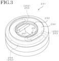
- FIG. 3 is a perspective view of the female terminal 231.
- FIG. 4 is a cross-sectional view around the snap connection portion 10. Note that FIG. 4 illustrates a state in the middle of insertion of the male terminal 331 into the recessed portion 232 of the female terminal 231.
- the female terminal 231 is a hollow member made from metal and has conductivity.
- the female terminal 231 protrudes in an upper direction from an upper surface of the insulator 22. That is, the upper surface of the insulator 22 constitutes a first fixing surface 222 having insulating property fixed to the electrode 21 side (female terminal 231 side) of the snap connection portion 10.
- the insulator 22 constitutes a first insulator having the first fixing surface 222.
- the biasing member 25 is, for example, a spring-like member formed by bending or curving one metal wire, and has conductivity.
- the biasing member 25 includes a pair of contact portions 251 extending substantially parallel to each other at a constant interval, and a coupling portion 252 coupling a pair of the contact portions 251.
- the coupling portion 252 includes a pair of spring portions 253 extending in an S shape from one end of each of the contact portions 251, and a fixing portion 254 that fixes the spring portion 253 to the female terminal 231.
- the biasing member 25 can change a distance between a pair of the contact portions 251 by elastic deformation in a pair of the spring portions 253.
- the fixing portion 254 is formed in an arc shape having a curvature corresponding to an inner peripheral surface of the female terminal 231.
- the fixing portion 254 is fixed in a state of abutting on the inner peripheral surface of the female terminal 231, so that the female terminal 231 and the biasing member 25 are electrically connected.
- An interval W between a pair of the contact portions 251 is smaller than an inner diameter of the recessed portion 232.
- a pair of the contact portions 251 are located in a lower direction of the recessed portion 232 and is exposed to the inner side than the recessed portion 232 (on a central axis L side of the female terminal 231) in plan view.
- the male terminal 331 is a metal member extending in a vertical direction and has conductivity.
- the male terminal 331 protrudes in a lower direction from a lower surface of the housing 31 of the main body 3. That is, the lower surface of the housing 31 of the main body 3 constitutes a second fixing surface 311 having insulating property fixed to the side (the male terminal 331 side) opposite to the electrode 21 side of the snap connection portion 10.
- the housing 31 constitutes a second insulator having the second fixing surface 311.
- a tapered surface 332 having a truncated cone shape formed to expand in a lower direction is formed at a lower end portion of the male terminal 331.
- the interval W between a pair of the contact portions 251 is smaller than an outer diameter of a lower end of the tapered surface 332 and larger than an outer diameter of an upper end of the tapered surface 332. That is, the interval W between a pair of the contact portions 251 coincides with an outer diameter in an intermediate portion of the tapered surface 332.
- the lower end of the tapered surface 332 is continuous with a lower end surface of the male terminal 331 via a smooth curved surface 333.
- the interval W between a pair of the contact portions 251 is equal to an outer diameter of an intermediate portion of the curved surface 333. Therefore, when a tip portion of the male terminal 331 is inserted into the recessed portion 232 from an upper direction as illustrated in FIG. 4 , first, a pair of the contact portions 251 come into contact with the curved surface 333. From this state, when the male terminal 331 is further pushed into the recessed portion 232, the biasing member 25 is elastically deformed, and a pair of the contact portions 251 are separated by the curved surface 333.
- the biasing member 25 is not limited to the above-described shape, and may have any configuration as long as the biasing member 25 applies a biasing force to the tapered surface 332 of the male terminal 331 received in the recessed portion 232.
- the seal portion 24 includes a peripheral wall 242 having a tubular shape and an extension portion 243 having an annular shape extending from an upper end surface of the peripheral wall 242 toward the central axis L side.
- the peripheral wall 242 and the extension portion 243 are integrally formed, and an inner surface shape of them substantially matches an outer surface shape of the female terminal 231.
- the seal portion 24 watertightly covers an outer periphery of the female terminal 231 in a state where an inner surface of the seal portion 24 is in close contact with a part of an upper surface and an outer peripheral surface of the female terminal 231.
- the seal portion 24 may be bonded to, or cover without being bonded to the female terminal 231.
- the opening 241 described above is formed at a central portion of the extension portion 243.
- the extension portion 243 extends on the receiving surface 230 of the female terminal 231 and annularly surrounds a periphery of the recessed portion 232.
- An upper surface of the extension portion 243 constitutes a contact surface 244 formed of a flat surface.
- the second fixing surface 311 facing the extension portion 243 in an upper direction is also formed of a flat surface, and the contact surface 244 of the seal portion 24 can be brought into close contact with the second fixing surface 311.
- FIGS. 5A and 5B are schematic cross-sectional views for explaining an aspect of snap connection by the snap connection portion 10.
- FIG. 5A illustrates a state before two of the connection portions 23 and 33 are electrically connected.
- FIG. 5B illustrates a state in which two of connection portions 23 and 33 are electrically connected.
- connection portions 23 and 33 When two of the connection portions 23 and 33 are brought close to each other from the state of FIG. 5A , a tip portion of the male terminal 331 is received in the recessed portion 232 of the female terminal 231 and comes into contact with a pair of the contact portions 251 of the biasing member 25. After the above, when the male terminal 331 is further pushed into the recessed portion 232, a pair of the contact portions 251 are in a state of being in contact with the tapered surface 332 as illustrated in FIG. 5B , and two of the connection portions 23 and 33 are snap-connected. At this time, the contact surface 244 of the seal portion 24 is in close contact with the second fixing surface 311 of the main body 3, and the seal portion 24 is in a state of being arranged between the first fixing surface 222 and the second fixing surface 311.
- a biasing force F1 acts on the tapered surface 332 from a pair of the contact portions 251. Since a contact surface of the male terminal 331 with respect to a pair of the contact portions 251 is the tapered surface 332, a force F2 for drawing into the recessed portion 232 acts on the male terminal 331 by the biasing force F1 from a pair of the contact portions 251. The force F2 acts in a direction in which the male terminal 331 and the female terminal 231 are moved closer to each other.
- a height H2 of the second fixing surface 311 with respect to the first fixing surface 222 in the state of FIG. 5B is lower than the height H1 of the seal portion 24 in the state of FIG. 5A . Therefore, in a state where the male terminal 331 is received in the female terminal 231 as illustrated in FIG. 5B , the seal portion 24 is compressed by being sandwiched between the first fixing surface 222 and the second fixing surface 311. At an upper end portion of the seal portion 24, the extension portion 243 is compressed by being sandwiched between the receiving surface 230 and the second fixing surface 311.
- a periphery of the male terminal 331 and the female terminal 231 becomes in a state of being sealed by the seal portion 24, and waterproof property of a contact portion between the male terminal 331 and the female terminal 231 is secured. That is, even in a case where liquid exists between the first fixing surface 222 and the second fixing surface 311, it is possible to prevent the liquid from entering a contact portion between the male terminal 331 and the female terminal 231.
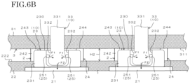
- FIGS. 6A and 6B are schematic cross-sectional views for explaining a variation of the insulator 22.
- FIG. 6A illustrates a state before two of the connection portions 23 and 33 are electrically connected.
- FIG. 6B illustrates a state in which two of the connection portions 23 and 33 are electrically connected. Note that, in FIGS. 6A and 6B , the same configurations as those in the above embodiment are denoted by the same reference numerals in the diagram, and detailed description of the configurations will be omitted.
- each of the connection portions 23 positioned on the electrode 21 side of each of the snap connection portions 10 is not individually fixed to two of the insulators 22, but is fixed to one of the insulator 22.
- An upper surface of the insulator 22 constitutes the first fixing surface 222, and the connection portions 23 are fixed to the common first fixing surface 222.
- the connection portion 33 of each of the snap connection portions 10 is fixed to the common second fixing surface 311 of the main body 3.
- the height H2 of the second fixing surface 311 with respect to the first fixing surface 222 in the state of FIG. 6B is lower than the height H1 of the seal portions 24 in the state of FIG. 6A . Therefore, in a state where a corresponding one of the male terminals 331 is received in each of the female terminals 231 as illustrated in FIG. 6B , each of the seal portions 24 is compressed by being sandwiched between the first fixing surface 222 and the second fixing surface 311. At an upper end portion of each of the seal portions 24, the extension portion 243 is compressed by being sandwiched between the receiving surface 230 and the second fixing surface 311.
- the seal portion 24 is not limited to the configuration in which two of the seal portions 24 are provided in a manner corresponding to the female terminals 231, and may have a configuration in which an outer periphery of the female terminals 231 is covered with the common seal portion 24. That is, two of the seal portions 24 in FIGS. 6A and 6B may be configured to be connected to each other.
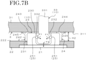
- FIGS. 7A and 7B are schematic cross-sectional views for explaining a first variation of the seal portion 24.
- FIG. 7A illustrates a state before two of the connection portions 23 and 33 are electrically connected.
- FIG. 7B illustrates a state in which two of the connection portions 23 and 33 are electrically connected. Note that, in FIGS. 7A and 7B , the same configurations as those in the above embodiment are denoted by the same reference numerals in the diagram, and detailed description of the configurations will be omitted.
- a sucker portion 245 is formed so as to protrude from a part of each of the seal portions 24.
- the sucker portion 245 may protrude from the peripheral wall 242 or may protrude from the extension portion 243.
- the sucker portion 245 is an annular member formed integrally with the seal portion 24, and has flexibility and waterproof property.
- An inner diameter of the sucker portion 245 is larger than the opening 241 formed on an upper end surface of the seal portion 24.
- the sucker portion 245 extends in a direction intersecting a direction in which the extension portion 243 extends. Specifically, the sucker portion 245 is formed in a truncated cone shape so as to expand with increasing distance from the first fixing surface 222.
- An angle of a direction in which the sucker portion 245 extends with respect to the direction in which extension portion 243 extends is larger than 90° and smaller than 180°, for example. The angle may be preferably 120° to 150°, and more preferably 130° to 140°.
- the sucker portion 245 has a cross-sectional shape tapered toward a tip portion.
- the tip portion of the sucker portion 245 extends to a position farther from the first fixing surface 222 than the contact surface 244 of the seal portion 24. Therefore, in a case where two of the connection portions 23 and 33 are brought close to each other from the state where two of the connection portions 23 and 33 face each other as illustrated in FIG. 7A , the tip portion of the sucker portion 245 comes into contact with the second fixing surface 311 of the main body 3 before the contact surface 244.
- the tip portion of the sucker portion 245 is expanded by the second fixing surface 311. Then, in a state where a tip portion of the male terminal 331 is received in the recessed portion 232 of the female terminal 231 as illustrated in FIG. 7B , air inside the sucker portion 245 is pushed out, so that the sucker portion 245 is adhered to the second fixing surface 311. In the state of FIG. 7B , at an upper end portion of the seal portion 24, the extension portion 243 is compressed by being sandwiched between the receiving surface 230 and the second fixing surface 311. Therefore, a periphery of the male terminal 331 and the female terminal 231 is sealed at two positions of the extension portion 243 and the sucker portion 245.
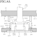
- FIGS. 8A and 8B are schematic cross-sectional views for explaining a second variation of the seal portion 24.
- FIG. 8A illustrates a state before two of the connection portions 23 and 33 are electrically connected.
- FIG. 8B illustrates a state in which two of the connection portions 23 and 33 are electrically connected. Note that, in FIGS. 8A and 8B , the same configurations as those in the above embodiment are denoted by the same reference numerals in the diagram, and detailed description of the configurations will be omitted.
- a seal portion 26 fixed to a lower surface of the housing 31 is provided separately from the seal portion 24 fixed to an upper surface of the insulator 22.
- the seal portion 26 is a tubular member, and is arranged at an interval around the male terminal 331 on the same axis.
- An inner diameter of the seal portion 26 is equal to or more than an outer diameter of the seal portion 24, and is equal to the outer diameter of the seal portion 24 in this example.
- a height of the seal portion 26 may be the same as the height H1 of the seal portion 24.
- the seal portion 26 can be formed of, for example, insulating resin such as urethane resin or silicone resin, but is not limited to these, and can be formed of various other materials having insulating property and waterproof property.
- a material of the seal portion 26 may be the same as or different from a material of the seal portion 24. Further, the seal portion 26 is not limited to a cylindrical shape, and may have another optional shape.
- FIGS. 9A and 9B are schematic cross-sectional views for explaining a third variation of the seal portion 24.
- FIG. 9A illustrates a state before two of the connection portions 23 and 33 are electrically connected.
- FIG. 9B illustrates a state in which two of the connection portions 23 and 33 are electrically connected. Note that, in FIGS. 9A and 9B , the same configurations as those in the above embodiment are denoted by the same reference numerals in the diagram, and detailed description of the configurations will be omitted.
- the seal portion 26 has a configuration different from that of the second variation.
- the seal portion 26 includes a tubular portion 261 and an end surface portion 262.
- the tubular portion 261 is a tubular member, and is arranged at an interval around the male terminal 331 on the same axis.
- An inner diameter of the tubular portion 261 is equal to or more than an outer diameter of the seal portion 24, and is equal to the outer diameter of the seal portion 24 in this example.
- a height of the tubular portion 261 may be the same as the height H1 of the seal portion 24.
- the end surface portion 262 is fixed in a manner abutting on a lower surface of the housing 31 and closes an upper end surface of the tubular portion 261.
- the seal portion 26 is positioned with respect to the male terminal 331 as the male terminal 331 penetrates a central portion of the end surface portion 262.
- the seal portion 24 may be fixed to the second fixing surface 311 instead of the first fixing surface 222.
- the seal portion 24 may have a configuration in which a first seal portion protruding in an upper direction from the first fixing surface 222 and a second seal portion protruding in a lower direction from the second fixing surface 311 are included, and tip portions of the first seal portion and the second seal portion abut on each other and are compressed by each other.
- the configuration may be such that the first seal portion is integrally formed with the first fixing surface 222, and the second seal portion is integrally formed with the second fixing surface 311.
- the configuration of the seal portion 24 is not limited to the configuration of being fixed to at least one of the first fixing surface 222 and the second fixing surface 311. That is, the seal portion 24 may be separated from the first fixing surface 222 and the second fixing surface 311. In this case, the seal portion 24 may be configured to be compressed as the male terminal 331 and the female terminal 231 are fitted to each other after the seal portion 24 is arranged between the first fixing surface 222 and the second fixing surface 311.
- the seal portion 24 does not need to be in contact with the snap connection portion 10. That is, the seal portion 24 may be configured to be arranged with respect to the snap connection portion 10 with a space between them. In this case, the seal portion 24 may be formed of a material having no insulating property.
- seal portion 24 may be formed, for example, by being applied to at least one of the first fixing surface 222 and the second fixing surface 311 instead of being formed in advance as a tubular member.
- the electrode 21 and the female terminal 231 may be electrically connected by wire or wirelessly, for example, without limitation to the configuration of being electrically connected by direct contact. Further, the male terminal 331 may be electrically connected to the main body 3 by wire or wirelessly, for example, without limitation to the configuration of being directly attached to the main body 3.
- the snap connection portion 10 is not limited to the configuration in which the connection portion 23 on the electrode 21 side has the female terminal 231 and the connection portion 33 on the side opposite to the electrode 21 side has the male terminal 331. That is, in the snap connection portion 10, the connection portion 23 on the electrode 21 side may have the male terminal 331, and the connection portion 33 on the opposite side to the electrode 21 side may have the female terminal 231.
- the number of the attachment portions 2 to be attached to and detached from a living body is not limited to two, and only one of the attachment portion 2 may be provided, or three or more of the attachment portions 2 may be provided.
- FIG. 10 is a schematic diagram illustrating a configuration example of the biological signal transmission device 1 according to a second embodiment.
- the description has been made on the configuration in which the main body 3 is attached to the attachment portion 2 so that the male terminal 331 and the female terminal 231 are electrically connected.
- the attachment portion 2 and the main body 3 are electrically connected via a wiring 12.
- the attachment portion 2 is provided with the male terminal 331 and the female terminal 231, and similar snap connection to that in the above embodiment is performed in the attachment portion 2.
- the degree of freedom in an attachment position of the attachment portion 2 with respect to a living body 5 is high.
- the attachment portion 2 can be attached to an optional position of a skin 50 of the living body 5.
- two of the attachment portions 2 are provided and attached to a forehead 51 and an ear 52.
- a fixture 11 for fixing the main body 3 to the living body 5 is provided.
- the main body 3 is attached to the fixture 11.
- Apart of the wiring 12 may be integrally held by the fixture 11.
- a biological signal transmission device includes:
- the snap connection portion may include:
- the seal portion in a state where the snap connection portion has the male terminal and the female terminal, and the male terminal is received in the female terminal, the seal portion is compressed by being sandwiched between the first fixing surface and the second fixing surface, and a periphery of the male terminal and the female terminal is in a state of being sealed by the seal portion. This makes it possible to prevent water from entering a connection portion between the male terminal and the female terminal from the outside.
- the biasing member comes into contact with the tapered surface of the male terminal and applies a force in a direction in which the male terminal and the female terminal are moved closer to each other.
- the extension portion of the female terminal extending on the receiving surface is in a compressed state, so that waterproof property of the connection portion between the male terminal and the female terminal can be further effectively improved.
- the seal portion may have a sucker portion extending in a direction intersecting a direction in which the extension portion extends, and may be configured such that the sucker portion is adhered to the first fixing surface or the second fixing surface in a state where the male terminal is received in the female terminal.
- the sucker portion in a state where the male terminal is received in the female terminal, the sucker portion is in a state of being adhered to the first fixing surface or the second fixing surface, and thus waterproof property of the connection portion between the male terminal and the female terminal can be further effectively improved.
- the seal portion is sandwiched and compressed between the first fixing surface of two of the first insulators individually fixed to the electrode side of each of the snap connection portions and the second fixing surface, so that it is possible to prevent water from entering the connection portion between the male terminal and the female terminal of each of the snap connection portions from the outside.
- the seal portion is sandwiched and compressed between the first fixing surface of the common first insulator fixed to the electrode side of each of the snap connection portions and the second fixing surface, so that it is possible to prevent water from entering the connection portion between the male terminal and the female terminal of each of the snap connection portions from the outside.
- the seal portion is sandwiched and compressed between the first fixing surface and the second insulator included in the main body, so that it is possible to prevent water from entering the connection portion between the male terminal and the female terminal of the snap connection portion from the outside.
Landscapes
- Life Sciences & Earth Sciences (AREA)
- Health & Medical Sciences (AREA)
- Medical Informatics (AREA)
- Biophysics (AREA)
- Pathology (AREA)
- Engineering & Computer Science (AREA)
- Biomedical Technology (AREA)
- Heart & Thoracic Surgery (AREA)
- Physics & Mathematics (AREA)
- Molecular Biology (AREA)
- Surgery (AREA)
- Animal Behavior & Ethology (AREA)
- General Health & Medical Sciences (AREA)
- Public Health (AREA)
- Veterinary Medicine (AREA)
- Connector Housings Or Holding Contact Members (AREA)
- Measurement And Recording Of Electrical Phenomena And Electrical Characteristics Of The Living Body (AREA)
Abstract
Description
- The present invention relates to a biological signal transmission device.
- Conventionally, a device that measures a signal (biological signal) generated from a living body is known. Examples of the biological signal include an action potential of a heart, as well as an action potential of a muscle other than a heart, an action potentials of a brain cell, and the like. By measuring these biological signals, an electrocardiogram, an electromyogram, an electroencephalogram, or the like can be obtained.
- This type of device includes an electrode attached to a living body (see, for example,
Patent Documents 1 to 3 below). InPatent Document 1, a conductive gel is connected to an external device D via a spring hook.Patent Document 2 exemplifies a snap as a shape of a connector in a connecting means to the outside. InPatent Document 3, a stud is connected to a terminal portion of an electrode body in order to prevent the electrode body from falling off a holder. -
- Patent Document 1:
JP 6221195 B2 - Patent Document 2:
JP H5-70552 Y - Patent Document 3:
JP 6181356 B2 - Use of a connection portion (snap connection portion) where electrical connection is made by fitting a male terminal and a female terminal together has an advantage that a conductor can be easily connected to an electrode. On the other hand, this type of connection portion is not usually provided with a waterproof measure, and is difficult to be used in water.
- For example, in a case of measuring a biological signal generated from a living body in water, an electrode is used in water. Since a connector electrically connected to an electrode attached to a living body in water is short-circuited by contact with water, a signal from the electrode cannot be normally transmitted. For this reason, in a configuration in which a biological signal is transmitted via a snap connection portion, it has not been easy to transmit a biological signal from a living body in water.
- The present invention has been made in view of the above circumstances, and an object of the present invention is to provide a biological signal transmission device in which waterproof property of a connection portion between a male terminal and a female terminal in a snap connection portion is improved.
- Afirst aspect of the present invention is a biological signal transmission device including an electrode, a snap connection portion, a first insulator, a second insulator, and a seal portion. The electrode is attached to a living body. The snap connection portion is electrically connected to the electrode. The first insulator has a first fixing surface fixed to the electrode side of the snap connection portion. The second insulator has a second fixing surface fixed to a side opposite to the electrode side of the snap connection portion. The seal portion is arranged between the first fixing surface and the second fixing surface.
- The snap connection portion includes a first connection portion, a second connection portion, and a biasing member. The first connection portion includes a male terminal on which a tapered surface is formed. The second connection portion has a female terminal that removably receives the male terminal, and is electrically connected to the first connection portion in a state where the male terminal is received in the female terminal. The biasing member comes into contact with the tapered surface of the male terminal received in the female terminal, and applies a force in a direction in which the male terminal and the female terminal are moved closer to each other.
- The seal portion is sandwiched and compressed between the first fixing surface and the second fixing surface in a state where the male terminal is received in the female terminal. In this manner, the seal portion is configured to seal a periphery of the male terminal and the female terminal. Further, the seal portion is configured to release the sealing state in a state where the male terminal is removed from the inside of the female terminal.
- According to a first aspect of the present invention, in a state where the snap connection portion has the male terminal and the female terminal, and the male terminal is received in the female terminal, the seal portion is compressed by being sandwiched between the first fixing surface and the second fixing surface, and a periphery of the male terminal and the female terminal is in a state of being sealed by the seal portion. This makes it possible to prevent water from entering a connection portion between the male terminal and the female terminal from the outside.
- In particular, in a state where the male terminal is received in the female terminal, the biasing member comes into contact with the tapered surface of the male terminal and applies a force in a direction in which the male terminal and the female terminal are moved closer to each other. By the above, since the seal portion sandwiched between the first fixing surface and the second fixing surface can be further compressed, waterproof property of the connection portion between the male terminal and the female terminal can be effectively improved.
-
-
FIG. 1 is a perspective view illustrating a configuration example of a biological signal transmission device according to a first embodiment. -
FIG. 2 is a side view of the biological signal transmission device ofFIG. 1 . -
FIG. 3 is a perspective view of a female terminal. -
FIG. 4 is a cross-sectional view around a snap connection portion. -
FIG. 5A is a schematic cross-sectional view for explaining a mode of snap connection by the snap connection portion, and illustrates a state before two connection portions are electrically connected. -
FIG. 5B is a schematic cross-sectional view for explaining a mode of snap connection by the snap connection portion, and illustrates a state in which two connection portions are electrically connected. -
FIG. 6A is a schematic cross-sectional view for explaining a variation of an insulator, illustrating a state before two connection portions are electrically connected. -
FIG. 6B is a schematic cross-sectional view for explaining the variation of the insulator, illustrating a state in which two connection portions are electrically connected. -
FIG. 7A is a schematic cross-sectional view for explaining a first variation of a seal portion, illustrating a state before two connection portions are electrically connected. -
FIG. 7B is a schematic cross-sectional view for explaining the first variation of the seal portion, illustrating a state in which two connection portions are electrically connected. -
FIG. 8A is a schematic cross-sectional view for explaining a second variation of the seal portion, illustrating a state before two connection portions are electrically connected. -
FIG. 8B is a schematic cross-sectional view for explaining the second variation of the seal portion, illustrating a state in which two connection portions are electrically connected. -
FIG. 9A is a schematic cross-sectional view for explaining a third variation of the seal portion, illustrating a state before two connection portions are electrically connected. -
FIG. 9B is a schematic cross-sectional view for explaining the third variation of the seal portion, illustrating a state in which two connection portions are electrically connected. -
FIG. 10 is a schematic diagram illustrating a configuration example of the biological signal transmission device according to a second embodiment. -
FIG. 1 is a perspective view illustrating a configuration example of a biologicalsignal transmission device 1 according to a first embodiment. The biologicalsignal transmission device 1 according to the present embodiment is a device for measuring a signal (biological signal) generated from a living body. A type of the biological signal is not limited as long as the biological signal is a signal detected from a living body, and examples of the biological signal include an action potential of a heart, an action potential of a muscle other than a heart, and an action potential of a brain cell. By acquiring these biological signals, an electrocardiogram, an electromyogram, an electroencephalogram, or the like can be obtained as a temporal change in potential. - The biological
signal transmission device 1 includes anattachment portion 2 attachable to and detachable from a living body and amain body 3 attachable to and detachable from theattachment portion 2. In the present embodiment, two of theattachment portions 2 are provided, and theattachment portions 2 are electrically connected to the commonmain body 3. - In the example of
FIG. 1 , two of theattachment portions 2 are held by acommon holding member 4. The holdingmember 4 is a member for facilitating attachment of each of theattachment portions 2 to a living body, and may be, for example, a band or a belt attached to the living body. InFIG. 1 , only a part of the holdingmember 4 is illustrated. However, the holdingmember 4 may be omitted, and each of theattachment portions 2 may be configured to be directly held by a living body. -
FIG. 2 is a side view of the biologicalsignal transmission device 1 ofFIG. 1 . Note that, inFIG. 2 , the holdingmember 4 is omitted from illustration. Hereinafter, an overall configuration of the biologicalsignal transmission device 1 will be described with reference toFIGS. 1 and2 . Note that, in description below, the upper side inFIG. 2 is defined as an upper direction, and the lower side is defined as a lower direction. - Each of the
attachment portions 2 includes anelectrode 21, aninsulator 22, aconnection portion 23, aseal portion 24, and the like. On the other hand, themain body 3 includes ahousing 31, acalculation unit 32, and the like. Twoconnection portions 33 protruding from a lower surface of thehousing 31 are fixed to themain body 3. The connection portion 33 (first connection portion) on themain body 3 side and the connection portion 23 (second connection portion) on theattachment portion 2 side constitute asnap connection portion 10 attachable to and detachable from each other. Theconnection portion 33 has amale terminal 331, and theconnection portion 23 has afemale terminal 231. As themale terminal 331 having a rod shape is fitted into thefemale terminal 231, themale terminal 331 and thefemale terminal 231 are electrically connected in an easily detachable state. - As described above, the biological
signal transmission device 1 according to the present embodiment includes two of theelectrodes 21 and two of thesnap connection portions 10. One of theelectrodes 21 is electrically connected to each of thesnap connection portions 10. Each of two of theinsulators 22 is individually fixed to each of theconnection portions 23 located on theelectrode 21 side of each of thesnap connection portions 10. - The
electrode 21 is, for example, a sheet-like member having adhesiveness, and is attached to a surface S of a living body with an easily peelable adhesive force. Theelectrode 21 is formed of, for example, gel-like conductive resin. In this example, theelectrode 21 is formed in a circular shape, but is not limited to a circular shape, and may have another shape such as a rectangular shape. Further, theelectrode 21 can be formed of, for example, silver paste, but is not limited to silver paste, and can be formed of various other materials having conductivity. - The
insulator 22 is, for example, a sheet-like member having insulating property and waterproof property. In this example, theinsulator 22 is formed in a circular shape having a larger diameter than theelectrode 21. However, theinsulator 22 is not limited to a circular shape, and may have another shape such as a rectangular shape. A recessedportion 221 is formed on a lower surface of theinsulator 22, and theelectrode 21 is fixed in a state of being accommodated in the recessedportion 221. A lower surface of theelectrode 21 accommodated in the recessedportion 221 is flush with the lower surface of theinsulator 22 or protrudes from the lower surface of theinsulator 22. Theinsulator 22 can be formed of, for example, insulating resin such as urethane resin or silicone resin, but is not limited to these, and can be formed of various other materials having insulating property and waterproof property. - The
connection portion 23 is electrically connected to theelectrode 21. Theconnection portion 23 has afemale terminal 231 having an annular shape formed of, for example, conductive metal. A lower surface of thefemale terminal 231 abuts on an upper surface of theelectrode 21. On an upper surface of thefemale terminal 231, a recessedportion 232 for removably receiving themale terminal 331 of theconnection portion 33 on themain body 3 side is formed. The upper surface of thefemale terminal 231 constitutes a receivingsurface 230. In the recessedportion 232 of thefemale terminal 231, themale terminal 331 is received from the tip, and in this state, theconnection portion 23 is electrically connected to theconnection portion 33. - The
seal portion 24 is a tubular member that covers an outer periphery of thefemale terminal 231. Theseal portion 24 has flexibility and waterproof property. Alower end surface of theseal portion 24 is fixed to an upper surface of theinsulator 22. A protruding amount of theseal portion 24 with respect to the upper surface of theinsulator 22 is larger than a protruding amount of thefemale terminal 231 with respect to the upper surface of theinsulator 22. - An
opening 241 is formed on an upper end surface of theseal portion 24. Theopening 241 has, for example, a circular shape, and has an inner diameter smaller than an outer diameter of thefemale terminal 231 and larger than an inner diameter of the female terminal 231 (inner diameter of the recessed portion 232). By the above, the recessedportion 232 of thefemale terminal 231 is exposed to the outside through theopening 241. - The
seal portion 24 may have any configuration as long as thefemale terminal 231 is accommodated in the inside and the recessedportion 232 of thefemale terminal 231 can be exposed to the outside. Therefore, theseal portion 24 is not limited to a cylindrical shape, and may have another optional shape. Theseal portion 24 can be formed of, for example, insulating resin such as urethane resin or silicone resin, but is not limited to these, and can be formed of various other materials having insulating property and waterproof property. - The
housing 31 of themain body 3 is a hard hollow member in which various components such as an electronic component are accommodated. Thehousing 31 can be formed of, for example, insulating resin such as polycarbonate resin or ABS resin, but is not limited to insulating resin, and can be formed of various other materials having insulating property and waterproof property. - In the present embodiment, the
housing 31 is composed of a member having a substantially rectangular shape in plan view. On a lower surface of thehousing 31, two of themale terminals 331 are arranged side by side along a longitudinal direction of thehousing 31, and each of themale terminals 331 protrudes in a lower direction. A distance between two of themale terminals 331 substantially coincides with a distance between the recessedportions 232 of two of thefemale terminals 231. Therefore, by bringing themain body 3 closer to two of theattachment portions 2, each of themale terminals 331 can be inserted into the recessedportion 232 of a corresponding one of thefemale terminals 231 at a time, and electrical connection by two of thesnap connection portions 10 can be simultaneously performed. - The
calculation unit 32 includes a processor such as a central processing unit (CPU), for example. Thecalculation unit 32 is accommodated in thehousing 31 and is electrically connected to each of themale terminals 331 via wiring (not illustrated). Thecalculation unit 32 processes a signal input from each of theelectrodes 21 via thesnap connection portion 10. Processing of a signal by thecalculation unit 32 includes various types of arithmetic processing for obtaining an electrocardiogram, an electromyogram, an electroencephalogram, or the like on the basis of the signal. -
FIG. 3 is a perspective view of thefemale terminal 231.FIG. 4 is a cross-sectional view around thesnap connection portion 10. Note thatFIG. 4 illustrates a state in the middle of insertion of themale terminal 331 into the recessedportion 232 of thefemale terminal 231. - The
female terminal 231 is a hollow member made from metal and has conductivity. Thefemale terminal 231 protrudes in an upper direction from an upper surface of theinsulator 22. That is, the upper surface of theinsulator 22 constitutes afirst fixing surface 222 having insulating property fixed to theelectrode 21 side (female terminal 231 side) of thesnap connection portion 10. Theinsulator 22 constitutes a first insulator having thefirst fixing surface 222. - Inside the
female terminal 231, a biasingmember 25 for making electrical connection with themale terminal 331 is provided. The biasingmember 25 is, for example, a spring-like member formed by bending or curving one metal wire, and has conductivity. Specifically, the biasingmember 25 includes a pair ofcontact portions 251 extending substantially parallel to each other at a constant interval, and acoupling portion 252 coupling a pair of thecontact portions 251. - The
coupling portion 252 includes a pair ofspring portions 253 extending in an S shape from one end of each of thecontact portions 251, and a fixingportion 254 that fixes thespring portion 253 to thefemale terminal 231. The biasingmember 25 can change a distance between a pair of thecontact portions 251 by elastic deformation in a pair of thespring portions 253. The fixingportion 254 is formed in an arc shape having a curvature corresponding to an inner peripheral surface of thefemale terminal 231. The fixingportion 254 is fixed in a state of abutting on the inner peripheral surface of thefemale terminal 231, so that thefemale terminal 231 and the biasingmember 25 are electrically connected. - An interval W between a pair of the
contact portions 251 is smaller than an inner diameter of the recessedportion 232. In a state where the biasingmember 25 is fixed in thefemale terminal 231, a pair of thecontact portions 251 are located in a lower direction of the recessedportion 232 and is exposed to the inner side than the recessed portion 232 (on a central axis L side of the female terminal 231) in plan view By the above, when a tip portion of themale terminal 331 is inserted into the recessedportion 232 from an upper direction as illustrated inFIG. 4 , the tip portion of themale terminal 331 comes into contact with a pair of thecontact portions 251. - The
male terminal 331 is a metal member extending in a vertical direction and has conductivity. Themale terminal 331 protrudes in a lower direction from a lower surface of thehousing 31 of themain body 3. That is, the lower surface of thehousing 31 of themain body 3 constitutes asecond fixing surface 311 having insulating property fixed to the side (themale terminal 331 side) opposite to theelectrode 21 side of thesnap connection portion 10. Thehousing 31 constitutes a second insulator having thesecond fixing surface 311. - A
tapered surface 332 having a truncated cone shape formed to expand in a lower direction is formed at a lower end portion of themale terminal 331. The interval W between a pair of thecontact portions 251 is smaller than an outer diameter of a lower end of the taperedsurface 332 and larger than an outer diameter of an upper end of the taperedsurface 332. That is, the interval W between a pair of thecontact portions 251 coincides with an outer diameter in an intermediate portion of the taperedsurface 332. - The lower end of the tapered
surface 332 is continuous with a lower end surface of themale terminal 331 via a smoothcurved surface 333. The interval W between a pair of thecontact portions 251 is equal to an outer diameter of an intermediate portion of thecurved surface 333. Therefore, when a tip portion of themale terminal 331 is inserted into the recessedportion 232 from an upper direction as illustrated inFIG. 4 , first, a pair of thecontact portions 251 come into contact with thecurved surface 333. From this state, when themale terminal 331 is further pushed into the recessedportion 232, the biasingmember 25 is elastically deformed, and a pair of thecontact portions 251 are separated by thecurved surface 333. - Then, when the
male terminal 331 is further pushed into the recessedportion 232, a pair of thecontact portions 251 climb over thecurved surface 333 and come into contact with thetapered surface 332. Since the taperedsurface 332 is tapered in an upper direction, an interval between a pair of thecontact portions 251 becomes closer to the initial interval W while thecontact portions 251 slide on thetapered surface 332. In this way, themale terminal 331 and thefemale terminal 231 are fitted at the position where a pair of thecontact portions 251 are in contact with an intermediate portion of the taperedsurface 332, and snap connection is achieved. - However, the biasing
member 25 is not limited to the above-described shape, and may have any configuration as long as the biasingmember 25 applies a biasing force to the taperedsurface 332 of themale terminal 331 received in the recessedportion 232. - As illustrated in
FIG. 4 , theseal portion 24 includes aperipheral wall 242 having a tubular shape and anextension portion 243 having an annular shape extending from an upper end surface of theperipheral wall 242 toward the central axis L side. Theperipheral wall 242 and theextension portion 243 are integrally formed, and an inner surface shape of them substantially matches an outer surface shape of thefemale terminal 231. Theseal portion 24 watertightly covers an outer periphery of thefemale terminal 231 in a state where an inner surface of theseal portion 24 is in close contact with a part of an upper surface and an outer peripheral surface of thefemale terminal 231. Theseal portion 24 may be bonded to, or cover without being bonded to thefemale terminal 231. - The
opening 241 described above is formed at a central portion of theextension portion 243. Theextension portion 243 extends on the receivingsurface 230 of thefemale terminal 231 and annularly surrounds a periphery of the recessedportion 232. An upper surface of theextension portion 243 constitutes acontact surface 244 formed of a flat surface. Thesecond fixing surface 311 facing theextension portion 243 in an upper direction is also formed of a flat surface, and thecontact surface 244 of theseal portion 24 can be brought into close contact with thesecond fixing surface 311. -
FIGS. 5A and5B are schematic cross-sectional views for explaining an aspect of snap connection by thesnap connection portion 10.FIG. 5A illustrates a state before two of theconnection portions FIG. 5B illustrates a state in which two ofconnection portions - When snap connection is performed by the
snap connection portion 10, first, as illustrated inFIG. 5A , two of theconnection portions seal portion 24 is not in contact with thesecond fixing surface 311 of themain body 3, and a height H1 of theseal portion 24 is a height in a normal state in which theseal portion 24 is not elastically deformed. - When two of the
connection portions FIG. 5A , a tip portion of themale terminal 331 is received in the recessedportion 232 of thefemale terminal 231 and comes into contact with a pair of thecontact portions 251 of the biasingmember 25. After the above, when themale terminal 331 is further pushed into the recessedportion 232, a pair of thecontact portions 251 are in a state of being in contact with thetapered surface 332 as illustrated inFIG. 5B , and two of theconnection portions contact surface 244 of theseal portion 24 is in close contact with thesecond fixing surface 311 of themain body 3, and theseal portion 24 is in a state of being arranged between thefirst fixing surface 222 and thesecond fixing surface 311. - In the state of
FIG. 5B , a biasing force F1 acts on thetapered surface 332 from a pair of thecontact portions 251. Since a contact surface of themale terminal 331 with respect to a pair of thecontact portions 251 is the taperedsurface 332, a force F2 for drawing into the recessedportion 232 acts on themale terminal 331 by the biasing force F1 from a pair of thecontact portions 251. The force F2 acts in a direction in which themale terminal 331 and thefemale terminal 231 are moved closer to each other. - A height H2 of the
second fixing surface 311 with respect to thefirst fixing surface 222 in the state ofFIG. 5B is lower than the height H1 of theseal portion 24 in the state ofFIG. 5A . Therefore, in a state where themale terminal 331 is received in thefemale terminal 231 as illustrated inFIG. 5B , theseal portion 24 is compressed by being sandwiched between thefirst fixing surface 222 and thesecond fixing surface 311. At an upper end portion of theseal portion 24, theextension portion 243 is compressed by being sandwiched between the receivingsurface 230 and thesecond fixing surface 311. - At this time, a periphery of the
male terminal 331 and thefemale terminal 231 becomes in a state of being sealed by theseal portion 24, and waterproof property of a contact portion between themale terminal 331 and thefemale terminal 231 is secured. That is, even in a case where liquid exists between thefirst fixing surface 222 and thesecond fixing surface 311, it is possible to prevent the liquid from entering a contact portion between themale terminal 331 and thefemale terminal 231. - When two of the
connection portions FIG. 5B , a tip portion of themale terminal 331 is removed from the inside of the recessedportion 232 of thefemale terminal 231 against the biasing force F1 of the biasingmember 25, and the state ofFIG. 5A is obtained again. In this state, thesecond fixing surface 311 of themain body 3 is in a non-contact state with thecontact surface 244 of theseal portion 24, so that the sealed state by theseal portion 24 is released. -
FIGS. 6A and6B are schematic cross-sectional views for explaining a variation of theinsulator 22.FIG. 6A illustrates a state before two of theconnection portions FIG. 6B illustrates a state in which two of theconnection portions FIGS. 6A and6B , the same configurations as those in the above embodiment are denoted by the same reference numerals in the diagram, and detailed description of the configurations will be omitted. - In this variation, each of the
connection portions 23 positioned on theelectrode 21 side of each of thesnap connection portions 10 is not individually fixed to two of theinsulators 22, but is fixed to one of theinsulator 22. An upper surface of theinsulator 22 constitutes thefirst fixing surface 222, and theconnection portions 23 are fixed to the commonfirst fixing surface 222. Further, theconnection portion 33 of each of thesnap connection portions 10 is fixed to the commonsecond fixing surface 311 of themain body 3. - An outer periphery of the
female terminal 231 of each of theconnection portions 33 is covered with an individual one of theseal portion 24. The shape of each of theseal portions 24 is the same. Therefore, in a normal state where theseal portion 24 is not elastically deformed as illustrated inFIG. 6A , the heights H1 of theseal portions 24 coincide with each other. When thefirst fixing surface 222 and thesecond fixing surface 311 are brought close to each other from the state ofFIG. 6A and each of themale terminals 331 is received in the recessedportion 232 of a corresponding one of thefemale terminals 231 as illustrated inFIG. 6B , the biasing force F1 acts on each of themale terminals 331 from the biasingmember 25 provided in each of thefemale terminals 231. - The height H2 of the
second fixing surface 311 with respect to thefirst fixing surface 222 in the state ofFIG. 6B is lower than the height H1 of theseal portions 24 in the state ofFIG. 6A . Therefore, in a state where a corresponding one of themale terminals 331 is received in each of thefemale terminals 231 as illustrated inFIG. 6B , each of theseal portions 24 is compressed by being sandwiched between thefirst fixing surface 222 and thesecond fixing surface 311. At an upper end portion of each of theseal portions 24, theextension portion 243 is compressed by being sandwiched between the receivingsurface 230 and thesecond fixing surface 311. - At this time, a periphery of each of the
male terminals 331 and each of thefemale terminals 231 becomes in a state of being sealed by theseal portion 24, and waterproof property of a contact portion between each of themale terminals 331 and each of thefemale terminals 231 is secured. That is, even in a case where liquid exists between thefirst fixing surface 222 and thesecond fixing surface 311, it is possible to prevent the liquid from entering a contact portion between themale terminal 331 and thefemale terminal 231. - However, the
seal portion 24 is not limited to the configuration in which two of theseal portions 24 are provided in a manner corresponding to thefemale terminals 231, and may have a configuration in which an outer periphery of thefemale terminals 231 is covered with thecommon seal portion 24. That is, two of theseal portions 24 inFIGS. 6A and6B may be configured to be connected to each other. -
FIGS. 7A and7B are schematic cross-sectional views for explaining a first variation of theseal portion 24.FIG. 7A illustrates a state before two of theconnection portions FIG. 7B illustrates a state in which two of theconnection portions FIGS. 7A and7B , the same configurations as those in the above embodiment are denoted by the same reference numerals in the diagram, and detailed description of the configurations will be omitted. - In this variation, a
sucker portion 245 is formed so as to protrude from a part of each of theseal portions 24. Thesucker portion 245 may protrude from theperipheral wall 242 or may protrude from theextension portion 243. Thesucker portion 245 is an annular member formed integrally with theseal portion 24, and has flexibility and waterproof property. An inner diameter of thesucker portion 245 is larger than theopening 241 formed on an upper end surface of theseal portion 24. - The
sucker portion 245 extends in a direction intersecting a direction in which theextension portion 243 extends. Specifically, thesucker portion 245 is formed in a truncated cone shape so as to expand with increasing distance from thefirst fixing surface 222. An angle of a direction in which thesucker portion 245 extends with respect to the direction in whichextension portion 243 extends is larger than 90° and smaller than 180°, for example. The angle may be preferably 120° to 150°, and more preferably 130° to 140°. - The
sucker portion 245 has a cross-sectional shape tapered toward a tip portion. The tip portion of thesucker portion 245 extends to a position farther from thefirst fixing surface 222 than thecontact surface 244 of theseal portion 24. Therefore, in a case where two of theconnection portions connection portions FIG. 7A , the tip portion of thesucker portion 245 comes into contact with thesecond fixing surface 311 of themain body 3 before thecontact surface 244. - When two of the
connection portions sucker portion 245 is expanded by thesecond fixing surface 311. Then, in a state where a tip portion of themale terminal 331 is received in the recessedportion 232 of thefemale terminal 231 as illustrated inFIG. 7B , air inside thesucker portion 245 is pushed out, so that thesucker portion 245 is adhered to thesecond fixing surface 311. In the state ofFIG. 7B , at an upper end portion of theseal portion 24, theextension portion 243 is compressed by being sandwiched between the receivingsurface 230 and thesecond fixing surface 311. Therefore, a periphery of themale terminal 331 and thefemale terminal 231 is sealed at two positions of theextension portion 243 and thesucker portion 245. -
FIGS. 8A and8B are schematic cross-sectional views for explaining a second variation of theseal portion 24.FIG. 8A illustrates a state before two of theconnection portions FIG. 8B illustrates a state in which two of theconnection portions FIGS. 8A and8B , the same configurations as those in the above embodiment are denoted by the same reference numerals in the diagram, and detailed description of the configurations will be omitted. - In this variation, a
seal portion 26 fixed to a lower surface of thehousing 31 is provided separately from theseal portion 24 fixed to an upper surface of theinsulator 22. Theseal portion 26 is a tubular member, and is arranged at an interval around themale terminal 331 on the same axis. An inner diameter of theseal portion 26 is equal to or more than an outer diameter of theseal portion 24, and is equal to the outer diameter of theseal portion 24 in this example. A height of theseal portion 26 may be the same as the height H1 of theseal portion 24. Theseal portion 26 can be formed of, for example, insulating resin such as urethane resin or silicone resin, but is not limited to these, and can be formed of various other materials having insulating property and waterproof property. A material of theseal portion 26 may be the same as or different from a material of theseal portion 24. Further, theseal portion 26 is not limited to a cylindrical shape, and may have another optional shape. - When two of the
connection portions FIG. 8A , a tip portion of themale terminal 331 is received in the recessedportion 232 of thefemale terminal 231 as inFIG. 8B . At this time, theseal portion 24 enters the inside of theseal portion 26, and each of theseal portion 24 and theseal portion 26 is compressed by being sandwiched between thefirst fixing surface 222 and thesecond fixing surface 311. By the above, a periphery of themale terminal 331 and thefemale terminal 231 becomes in a state of being sealed by theseal portion 24 and theseal portion 26, and waterproof property of a contact portion between themale terminal 331 and thefemale terminal 231 is secured. -
FIGS. 9A and9B are schematic cross-sectional views for explaining a third variation of theseal portion 24.FIG. 9A illustrates a state before two of theconnection portions FIG. 9B illustrates a state in which two of theconnection portions FIGS. 9A and9B , the same configurations as those in the above embodiment are denoted by the same reference numerals in the diagram, and detailed description of the configurations will be omitted. - In this variation, the
seal portion 26 has a configuration different from that of the second variation. Specifically, theseal portion 26 includes atubular portion 261 and anend surface portion 262. Thetubular portion 261 is a tubular member, and is arranged at an interval around themale terminal 331 on the same axis. An inner diameter of thetubular portion 261 is equal to or more than an outer diameter of theseal portion 24, and is equal to the outer diameter of theseal portion 24 in this example. A height of thetubular portion 261 may be the same as the height H1 of theseal portion 24. - The
end surface portion 262 is fixed in a manner abutting on a lower surface of thehousing 31 and closes an upper end surface of thetubular portion 261. Theseal portion 26 is positioned with respect to themale terminal 331 as themale terminal 331 penetrates a central portion of theend surface portion 262. By the above, it is possible to prevent theseal portion 26 from being displaced with respect to themale terminal 331 and to improve relative positional accuracy between theseal portion 24 and theseal portion 26 when a tip portion of themale terminal 331 is received in the recessedportion 232 of thefemale terminal 231. When theseal portion 24 enters the inside of theseal portion 26 as illustrated inFIG. 9B from the state ofFIG. 9A , theend surface portion 262 of theseal portion 26 abuts on and is in close contact with an upper end surface of theseal portion 24, so that waterproofness of a contact portion between themale terminal 331 and thefemale terminal 231 is further improved. - The
seal portion 24 may be fixed to thesecond fixing surface 311 instead of thefirst fixing surface 222. Alternatively, theseal portion 24 may have a configuration in which a first seal portion protruding in an upper direction from thefirst fixing surface 222 and a second seal portion protruding in a lower direction from thesecond fixing surface 311 are included, and tip portions of the first seal portion and the second seal portion abut on each other and are compressed by each other. In this case, the configuration may be such that the first seal portion is integrally formed with thefirst fixing surface 222, and the second seal portion is integrally formed with thesecond fixing surface 311. - The configuration of the
seal portion 24 is not limited to the configuration of being fixed to at least one of thefirst fixing surface 222 and thesecond fixing surface 311. That is, theseal portion 24 may be separated from thefirst fixing surface 222 and thesecond fixing surface 311. In this case, theseal portion 24 may be configured to be compressed as themale terminal 331 and thefemale terminal 231 are fitted to each other after theseal portion 24 is arranged between thefirst fixing surface 222 and thesecond fixing surface 311. - The
seal portion 24 does not need to be in contact with thesnap connection portion 10. That is, theseal portion 24 may be configured to be arranged with respect to thesnap connection portion 10 with a space between them. In this case, theseal portion 24 may be formed of a material having no insulating property. - Further, the
seal portion 24 may be formed, for example, by being applied to at least one of thefirst fixing surface 222 and thesecond fixing surface 311 instead of being formed in advance as a tubular member. - The
electrode 21 and thefemale terminal 231 may be electrically connected by wire or wirelessly, for example, without limitation to the configuration of being electrically connected by direct contact. Further, themale terminal 331 may be electrically connected to themain body 3 by wire or wirelessly, for example, without limitation to the configuration of being directly attached to themain body 3. - The
snap connection portion 10 is not limited to the configuration in which theconnection portion 23 on theelectrode 21 side has thefemale terminal 231 and theconnection portion 33 on the side opposite to theelectrode 21 side has themale terminal 331. That is, in thesnap connection portion 10, theconnection portion 23 on theelectrode 21 side may have themale terminal 331, and theconnection portion 33 on the opposite side to theelectrode 21 side may have thefemale terminal 231. - Note that the number of the
attachment portions 2 to be attached to and detached from a living body is not limited to two, and only one of theattachment portion 2 may be provided, or three or more of theattachment portions 2 may be provided. -
FIG. 10 is a schematic diagram illustrating a configuration example of the biologicalsignal transmission device 1 according to a second embodiment. In the above embodiment, the description has been made on the configuration in which themain body 3 is attached to theattachment portion 2 so that themale terminal 331 and thefemale terminal 231 are electrically connected. On the other hand, in the present embodiment, theattachment portion 2 and themain body 3 are electrically connected via awiring 12. In this case, theattachment portion 2 is provided with themale terminal 331 and thefemale terminal 231, and similar snap connection to that in the above embodiment is performed in theattachment portion 2. - In the present embodiment, since the
attachment portion 2 and themain body 3 are electrically connected via thewiring 12, the degree of freedom in an attachment position of theattachment portion 2 with respect to aliving body 5 is high. Theattachment portion 2 can be attached to an optional position of askin 50 of the livingbody 5. For example, in a case of measuring a brain wave, as illustrated inFIG. 10 , two of theattachment portions 2 are provided and attached to aforehead 51 and anear 52. - In this example, a fixture 11 for fixing the
main body 3 to the livingbody 5 is provided. Themain body 3 is attached to the fixture 11. Apart of thewiring 12 may be integrally held by the fixture 11. - It is understood by those skilled in the art that a plurality of the exemplary embodiments described above are specific examples of an aspect below.
- (Clause 1) A biological signal transmission device according to an aspect includes:
- an electrode attached to a living body;
- a snap connection portion electrically connected to the electrode;
- a first insulator having a first fixing surface fixed to the electrode side of the snap connection portion;
- a second insulator having a second fixing surface fixed to a side opposite to the electrode side of the snap connection portion; and
- a seal portion arranged between the first fixing surface and the second fixing surface.
- The snap connection portion may include:
- a first connection portion having a male or protruding terminal on which a tapered surface is formed;
- a second connection portion having a female or recessed terminal for removably receiving the male terminal, the second connection portion being electrically connected to the first connection portion in a state where the male terminal is received in the female terminal; and
- a biasing member that comes into contact with the tapered surface of the male terminal received in the female terminal and is arranged to apply a force in a direction in which the male terminal and the female terminal are moved closer to each other, and
- the seal portion may be configured to:
- seal a periphery of the male terminal and the female terminal with being sandwiched and compressed between the first fixing surface and the second fixing surface in response to the reception of the male terminal into the female terminal; and
- release the sealing state in response to the removal of the male terminal out of the female terminal.
- According to the biological signal transmission device described in
Clause 1, in a state where the snap connection portion has the male terminal and the female terminal, and the male terminal is received in the female terminal, the seal portion is compressed by being sandwiched between the first fixing surface and the second fixing surface, and a periphery of the male terminal and the female terminal is in a state of being sealed by the seal portion. This makes it possible to prevent water from entering a connection portion between the male terminal and the female terminal from the outside. - In particular, in a state where the male terminal is received in the female terminal, the biasing member comes into contact with the tapered surface of the male terminal and applies a force in a direction in which the male terminal and the female terminal are moved closer to each other. By the above, since the seal portion sandwiched between the first fixing surface and the second fixing surface can be further compressed, waterproof property of the connection portion between the male terminal and the female terminal can be effectively improved.
- (Clause 2) In the biological signal transmission device described in
Clause 1, - the female terminal may have a recessed portion that receives the male terminal, and a receiving surface on which the recessed portion is formed, and
- the seal portion may have an extension portion extending on the receiving surface of the female terminal, and be configured such that the extension portion is compressed in a state where the male terminal is received in the female terminal.
- According to the biological signal transmission device described in
Clause 2, in a state where the male terminal is received in the female terminal, the extension portion of the female terminal extending on the receiving surface is in a compressed state, so that waterproof property of the connection portion between the male terminal and the female terminal can be further effectively improved. - (Clause 3) In the biological signal transmission device described in
Clause 2,
the seal portion may have a sucker portion extending in a direction intersecting a direction in which the extension portion extends, and may be configured such that the sucker portion is adhered to the first fixing surface or the second fixing surface in a state where the male terminal is received in the female terminal. - According to the biological signal transmission device described in
Clause 3, in a state where the male terminal is received in the female terminal, the sucker portion is in a state of being adhered to the first fixing surface or the second fixing surface, and thus waterproof property of the connection portion between the male terminal and the female terminal can be further effectively improved. - (Clause 4) In the biological signal transmission device described in any one of
Clauses 1 to 3, - two of the electrodes and two of the snap connection portions may be included, and
- the electrode may be electrically connected one by one to each of the snap connection portions.
- According to the biological signal transmission device described in
Clause 4, it is possible to prevent a short circuit from occurring between two of the electrodes and two of the snap connection portions. - (Clause 5) In the biological signal transmission device described in
Clause 4, - two of the first insulators on each of which the first fixing surface is formed may be included, and
- each of two of the first insulators may be individually fixed to the electrode side of each of the snap connection portions.
- According to the biological signal transmission device described in
Clause 5, the seal portion is sandwiched and compressed between the first fixing surface of two of the first insulators individually fixed to the electrode side of each of the snap connection portions and the second fixing surface, so that it is possible to prevent water from entering the connection portion between the male terminal and the female terminal of each of the snap connection portions from the outside. - (Clause 6) In the biological signal transmission device described in
Clause 4, - one of the first insulator on which the first fixing surface is formed may be included, and
- one of the first insulator may be fixed to the electrode side of each of the snap connection portions.
- According to the biological signal transmission device described in Clause 6, the seal portion is sandwiched and compressed between the first fixing surface of the common first insulator fixed to the electrode side of each of the snap connection portions and the second fixing surface, so that it is possible to prevent water from entering the connection portion between the male terminal and the female terminal of each of the snap connection portions from the outside.
- (Clause 7) In the biological signal transmission device described in any one of
Clauses 1 to 6, - the biological signal transmission device further includes a main body including a calculation unit that processes a signal input from the electrode, and
- the second insulator may be included in the main body.
- According to the biological signal transmission device described in Clause 7, the seal portion is sandwiched and compressed between the first fixing surface and the second insulator included in the main body, so that it is possible to prevent water from entering the connection portion between the male terminal and the female terminal of the snap connection portion from the outside.
-
- 1
- biological signal transmission device
- 2
- attachment portion
- 3
- main body
- 4
- holding member
- 5
- living body
- 10
- snap connection portion
- 21
- electrode
- 22
- insulator (first insulator)
- 23
- connection portion
- 24
- seal portion
- 25
- biasing member
- 26
- seal portion
- 31
- housing (second insulator)
- 32
- calculation unit
- 33
- connection portion
- 221
- recessed portion
- 222
- first fixing surface
- 230
- receiving surface
- 231
- female terminal
- 232
- recessed portion
- 241
- opening
- 242
- peripheral wall
- 243
- extension portion
- 244
- contact surface
- 311
- second fixing surface
- 331
- male terminal
- 332
- tapered surface
Claims (7)
- A biological signal transmission device comprising:an electrode attached to a living body;a snap connection portion electrically connected to the electrode;a first insulator having a first fixing surface fixed to the electrode side of the snap connection portion;a second insulator having a second fixing surface fixed to a side opposite to the electrode side of the snap connection portion; anda seal portion arranged between the first fixing surface and the second fixing surface, whereinthe snap connection portion includes:a first connection portion having a male terminal on which a tapered surface is formed;a second connection portion having a female terminal for removably receiving the male terminal, the second connection portion being electrically connected to the first connection portion in a state where the male terminal is received in the female terminal; anda biasing member that comes into contact with the tapered surface of the male terminal received in the female terminal and is arranged to apply a force in a direction in which the male terminal and the female terminal are moved closer to each other, andthe seal portion is configured to:seal a periphery of the male terminal and the female terminal with being sandwiched and compressed between the first fixing surface and the second fixing surface in response to the reception of the male terminal into the female terminal; andrelease the sealing state in response to the removal of the male terminal out of the female terminal.
- The biological signal transmission device according to claim 1, whereinthe female terminal has a recessed portion that receives the male terminal, and a receiving surface on which the recessed portion is formed, andthe seal portion has an extension portion extending on the receiving surface of the female terminal, and is configured such that the extension portion is compressed in a state where the male terminal is received in the female terminal.
- The biological signal transmission device according to claim 2, wherein
the seal portion has a sucker portion extending in a direction intersecting a direction in which the extension portion extends, and is configured such that the sucker portion is adhered to the first fixing surface or the second fixing surface in a state where the male terminal is received in the female terminal. - The biological signal transmission device according to claim 1, whereintwo of the electrodes and two of the snap connection portions are included, andthe electrode is electrically connected one by one to each of the snap connection portions.
- The biological signal transmission device according to claim 4, whereintwo of the first insulators on each of which the first fixing surface is formed is included, andeach of two of the first insulators is individually fixed to the electrode side of each of the snap connection portions.
- The biological signal transmission device according to claim 4, whereinone of the first insulator on which the first fixing surface is formed is included, andone of the first insulator is fixed to the electrode side of each of the snap connection portions.
- The biological signal transmission device according to claim 1, further comprising:a main body including a calculation unit that processes a signal input from the electrode, whereinthe second insulator is included in the main body.
Applications Claiming Priority (2)
| Application Number | Priority Date | Filing Date | Title |
|---|---|---|---|
| JP2020163297 | 2020-09-29 | ||
| PCT/JP2021/033561 WO2022070865A1 (en) | 2020-09-29 | 2021-09-13 | Biological signal transmission device |
Publications (2)
| Publication Number | Publication Date |
|---|---|
| EP4223221A1 true EP4223221A1 (en) | 2023-08-09 |
| EP4223221A4 EP4223221A4 (en) | 2024-03-13 |
Family
ID=80951392
Family Applications (1)
| Application Number | Title | Priority Date | Filing Date |
|---|---|---|---|
| EP21875167.5A Withdrawn EP4223221A4 (en) | 2020-09-29 | 2021-09-13 | DEVICE FOR TRANSMITTING BIOLOGICAL SIGNALS |
Country Status (5)
| Country | Link |
|---|---|
| US (1) | US20230363682A1 (en) |
| EP (1) | EP4223221A4 (en) |
| JP (1) | JPWO2022070865A1 (en) |
| CN (1) | CN116249485A (en) |
| WO (1) | WO2022070865A1 (en) |
Families Citing this family (1)
| Publication number | Priority date | Publication date | Assignee | Title |
|---|---|---|---|---|
| WO2026047836A1 (en) * | 2024-08-27 | 2026-03-05 | Ntt株式会社 | Adaptor |
Family Cites Families (11)
| Publication number | Priority date | Publication date | Assignee | Title |
|---|---|---|---|---|
| JP2009517160A (en) * | 2005-11-30 | 2009-04-30 | コーニンクレッカ フィリップス エレクトロニクス エヌ ヴィ | Electromechanical connector for thin medical monitoring patch |
| JPWO2013088747A1 (en) * | 2011-12-15 | 2015-04-27 | 株式会社テクノ・コモンズ | Biological information detection unit |
| JP6181356B2 (en) * | 2012-06-28 | 2017-08-16 | 株式会社アイ・メデックス | Bioelectrode pad |
| US10413251B2 (en) * | 2012-10-07 | 2019-09-17 | Rhythm Diagnostic Systems, Inc. | Wearable cardiac monitor |
| US9861291B2 (en) * | 2012-12-31 | 2018-01-09 | Suunto Oy | Electrode assembly |
| JP6221195B2 (en) | 2014-12-08 | 2017-11-01 | 株式会社プロキダイ | Biological electrode |
| WO2016134473A1 (en) * | 2015-02-27 | 2016-09-01 | Icentia Inc. | Wearable physiological data acquirer and methods of using same |
| US10874351B2 (en) * | 2015-03-20 | 2020-12-29 | Zentan Technology Co., Ltd. | Physiological signal detecting apparatus and physiological signal detecting device |
| US10485443B2 (en) * | 2016-06-20 | 2019-11-26 | Halo Neuro, Inc. | Electrical interface system |
| JP2019037693A (en) * | 2017-08-29 | 2019-03-14 | Smk株式会社 | Biological information acquisition device |
| CN112839585A (en) * | 2018-10-10 | 2021-05-25 | 元素科学公司 | Wearable device with disposable parts and reusable parts |
-
2021
- 2021-09-13 CN CN202180064350.2A patent/CN116249485A/en not_active Withdrawn
- 2021-09-13 US US18/028,133 patent/US20230363682A1/en not_active Abandoned
- 2021-09-13 WO PCT/JP2021/033561 patent/WO2022070865A1/en not_active Ceased
- 2021-09-13 JP JP2022553774A patent/JPWO2022070865A1/ja active Pending
- 2021-09-13 EP EP21875167.5A patent/EP4223221A4/en not_active Withdrawn
Also Published As
| Publication number | Publication date |
|---|---|
| EP4223221A4 (en) | 2024-03-13 |
| JPWO2022070865A1 (en) | 2022-04-07 |
| WO2022070865A1 (en) | 2022-04-07 |
| CN116249485A (en) | 2023-06-09 |
| US20230363682A1 (en) | 2023-11-16 |
Similar Documents
| Publication | Publication Date | Title |
|---|---|---|
| US8251736B2 (en) | Connector assembly for connecting an electrical lead to an electrode | |
| US8838198B2 (en) | Electrode system | |
| US8463354B2 (en) | Electrode system with rigid-flex circuit | |
| CN107949323B (en) | Biological information measuring device | |
| US20100016701A1 (en) | Flexible electrode assembly and apparatus for measuring electrophysiological signals | |
| US20190343458A1 (en) | Assembled head-mounted module for sensing brain activity and head-mounted device for sensing brain activity | |
| EP3260044A1 (en) | Myoelectric sensor | |
| CN111419218A (en) | Wearable electronic equipment | |
| US11045093B2 (en) | Sensor unit | |
| EP4223221A1 (en) | Biological signal transmission device | |
| KR101935666B1 (en) | Detachable needle electrode and multi-channel wireless intraoperative neuromonitoring system having the same | |
| KR100773447B1 (en) | Biological electrodes and biosignal measuring devices | |
| US11517237B2 (en) | Adapter and external support structure for biosignal measurement system, biosignal measurement system and connection method | |
| US20200221967A1 (en) | Brain wave detection bioelectrode | |
| CN219183789U (en) | Electroencephalogram signal acquisition device | |
| JP5913485B2 (en) | Biological signal monitoring system | |
| JP2016104255A (en) | Biological signal monitor system | |
| JP2016007447A (en) | Biological information detection apparatus and manufacturing method for biological information detection apparatus | |
| EP4588439A1 (en) | Electrode member and bioelectric signal measuring electrode | |
| CN120788587B (en) | Bioelectric signal detection module and bioelectric signal detection device | |
| KR100855247B1 (en) | Biological electrodes and biosignal measuring apparatus including the same | |
| CN211432887U (en) | Electrocardiograph recorder and detection system | |
| US11522314B2 (en) | Base and detection apparatus | |
| WO2020095396A1 (en) | Electrode and signal measurement device |
Legal Events
| Date | Code | Title | Description |
|---|---|---|---|
| STAA | Information on the status of an ep patent application or granted ep patent |
Free format text: STATUS: THE INTERNATIONAL PUBLICATION HAS BEEN MADE |
|
| PUAI | Public reference made under article 153(3) epc to a published international application that has entered the european phase |
Free format text: ORIGINAL CODE: 0009012 |
|
| STAA | Information on the status of an ep patent application or granted ep patent |
Free format text: STATUS: REQUEST FOR EXAMINATION WAS MADE |
|
| 17P | Request for examination filed |
Effective date: 20230418 |
|
| AK | Designated contracting states |
Kind code of ref document: A1 Designated state(s): AL AT BE BG CH CY CZ DE DK EE ES FI FR GB GR HR HU IE IS IT LI LT LU LV MC MK MT NL NO PL PT RO RS SE SI SK SM TR |
|
| DAV | Request for validation of the european patent (deleted) | ||
| DAX | Request for extension of the european patent (deleted) | ||
| A4 | Supplementary search report drawn up and despatched |
Effective date: 20240213 |
|
| RIC1 | Information provided on ipc code assigned before grant |
Ipc: A61B 5/274 20210101ALI20240207BHEP Ipc: A61B 5/25 20210101ALI20240207BHEP Ipc: A61B 5/273 20210101AFI20240207BHEP |
|
| STAA | Information on the status of an ep patent application or granted ep patent |
Free format text: STATUS: THE APPLICATION IS DEEMED TO BE WITHDRAWN |
|
| 18D | Application deemed to be withdrawn |
Effective date: 20240903 |