EP4223161A1 - Sensor for aerosol generation apparatus, aerosol generation apparatus and temperature measurement apparatus - Google Patents
Sensor for aerosol generation apparatus, aerosol generation apparatus and temperature measurement apparatus Download PDFInfo
- Publication number
- EP4223161A1 EP4223161A1 EP21874545.3A EP21874545A EP4223161A1 EP 4223161 A1 EP4223161 A1 EP 4223161A1 EP 21874545 A EP21874545 A EP 21874545A EP 4223161 A1 EP4223161 A1 EP 4223161A1
- Authority
- EP
- European Patent Office
- Prior art keywords
- metal material
- sensing part
- base body
- generation apparatus
- aerosol generation
- Prior art date
- Legal status (The legal status is an assumption and is not a legal conclusion. Google has not performed a legal analysis and makes no representation as to the accuracy of the status listed.)
- Pending
Links
Images


Classifications
-
- A—HUMAN NECESSITIES
- A24—TOBACCO; CIGARS; CIGARETTES; SIMULATED SMOKING DEVICES; SMOKERS' REQUISITES
- A24F—SMOKERS' REQUISITES; MATCH BOXES; SIMULATED SMOKING DEVICES
- A24F40/00—Electrically operated smoking devices; Component parts thereof; Manufacture thereof; Maintenance or testing thereof; Charging means specially adapted therefor
- A24F40/50—Control or monitoring
- A24F40/51—Arrangement of sensors
-
- A—HUMAN NECESSITIES
- A24—TOBACCO; CIGARS; CIGARETTES; SIMULATED SMOKING DEVICES; SMOKERS' REQUISITES
- A24F—SMOKERS' REQUISITES; MATCH BOXES; SIMULATED SMOKING DEVICES
- A24F40/00—Electrically operated smoking devices; Component parts thereof; Manufacture thereof; Maintenance or testing thereof; Charging means specially adapted therefor
- A24F40/40—Constructional details, e.g. connection of cartridges and battery parts
- A24F40/46—Shape or structure of electric heating means
- A24F40/465—Shape or structure of electric heating means specially adapted for induction heating
-
- H—ELECTRICITY
- H05—ELECTRIC TECHNIQUES NOT OTHERWISE PROVIDED FOR
- H05B—ELECTRIC HEATING; ELECTRIC LIGHT SOURCES NOT OTHERWISE PROVIDED FOR; CIRCUIT ARRANGEMENTS FOR ELECTRIC LIGHT SOURCES, IN GENERAL
- H05B6/00—Heating by electric, magnetic or electromagnetic fields
- H05B6/02—Induction heating
- H05B6/10—Induction heating apparatus, other than furnaces, for specific applications
- H05B6/105—Induction heating apparatus, other than furnaces, for specific applications using a susceptor
-
- H—ELECTRICITY
- H05—ELECTRIC TECHNIQUES NOT OTHERWISE PROVIDED FOR
- H05B—ELECTRIC HEATING; ELECTRIC LIGHT SOURCES NOT OTHERWISE PROVIDED FOR; CIRCUIT ARRANGEMENTS FOR ELECTRIC LIGHT SOURCES, IN GENERAL
- H05B6/00—Heating by electric, magnetic or electromagnetic fields
- H05B6/02—Induction heating
- H05B6/10—Induction heating apparatus, other than furnaces, for specific applications
- H05B6/105—Induction heating apparatus, other than furnaces, for specific applications using a susceptor
- H05B6/108—Induction heating apparatus, other than furnaces, for specific applications using a susceptor for heating a fluid
-
- A—HUMAN NECESSITIES
- A24—TOBACCO; CIGARS; CIGARETTES; SIMULATED SMOKING DEVICES; SMOKERS' REQUISITES
- A24F—SMOKERS' REQUISITES; MATCH BOXES; SIMULATED SMOKING DEVICES
- A24F40/00—Electrically operated smoking devices; Component parts thereof; Manufacture thereof; Maintenance or testing thereof; Charging means specially adapted therefor
- A24F40/20—Devices using solid inhalable precursors
Definitions
- Embodiments of this application relate to the field of heat-not-burn cigarette devices of an electromagnetic induction type, and in particular, to a susceptor for an aerosol generation apparatus, an aerosol generation apparatus, and a temperature measurement apparatus.
- Tobacco products (such as cigarettes and cigars) burn tobacco during use to produce tobacco smoke. Attempts are made to replace these tobacco-burning products by manufacturing products that release compounds without burning.
- a heating apparatus that releases compounds by heating rather than burning materials.
- the materials may be tobacco or other non-tobacco products. These non-tobacco products may or may not include nicotine.
- temperature monitoring is required in a process of heating a tobacco product.
- such a product is attached to a heating component through a temperature sensor, to obtain a temperature of the heating component.
- An embodiment of this application provides an aerosol generation apparatus, configured to heat an aerosol-forming article to generate an aerosol, and including:
- the metal base body is substantially constructed to be coaxial with the sensing part and in a shape of a sheet or a column.
- the susceptor further includes: a support member, located in the hollow of the sensing part and providing support for the metal base body, to cause the metal base body to abut against the sensing part.
- the sensing part includes a pointed end configured to be inserted into the aerosol-forming article and a far end facing away from the pointed end; and the metal base body includes a first surface close to the pointed end along the axial direction and a second surface facing away from the first surface; and the support member supports the metal base body on the second surface, to cause the first surface to abut against the sensing part.
- the second surface is a flat surface extending along a cross-sectional direction of the susceptor.
- the sensing part includes a pointed end configured to be inserted into the aerosol-forming article; and the metal base body includes a first surface close to the pointed end along the axial direction, where the first surface is a flat surface extending along the cross-sectional direction of the susceptor.
- the first metal material and/or the second metal material run through the metal base body along the axial direction.
- the first metal material and/or the second metal material are connected to the first surface of the metal base body.
- the first metal material and/or the second metal material do not protrude from the first surface of the metal base body.
- the support member is constructed to be coaxial with the sensing part and in a shape of a column or a tube.
- a first through hole and a second through hole that are arranged along the axial direction of the susceptor are provided on the support member; and the first metal material at least partially extends in the first through hole, and the second metal material at least partially extends in the second through hole.
- a base part extending to the outside along a radial direction is further arranged in the sensing part, and the susceptor is held in the aerosol generation apparatus through the base part.
- the first metal material and/or the second metal material are constructed to be in shapes of elongated filaments and at least partially run through the sensing part.
- the sensing part and the metal base body are made of the same material.
- An embodiment of this application further provides a susceptor for an aerosol generation apparatus, including: a sensing part, constructed to include a hollow extending along a length direction of the susceptor; and a metal base body, located in the hollow of the sensing part and abutting against the sensing part, where a first metal material and a second metal material are connected to the metal base body, and the first metal material and the second metal material are made of different materials, to cause a thermocouple configured to sense a temperature of the sensing part to be formed between the first metal material and the second metal material.
- An embodiment of this application further provides a temperature measurement apparatus, including a metal base body, where a first metal material and a second metal material are connected to the metal base body, and the first metal material and the second metal material are made of different materials, to cause a thermocouple configured to sense a temperature to be formed between the first metal material and the second metal material.
- thermocouple that can be configured to measure a temperature is formed by simultaneously connecting the first metal material and the second metal material that are made of different materials to the metal base body, thereby achieving a more accurate temperature measurement effect.
- FIG. 1 An embodiment of this application provides an aerosol generation apparatus and a structure thereof may refer to FIG. 1 .
- the apparatus includes:
- the induction coil L may be a cylindrical induction coil wound into a helical shape, as shown in FIG. 1 .
- a radius r of the cylindrical induction coil L wound into the helical shape may range from about 5 mm to about 10 mm, and particularly, the radius r may be about 7 mm.
- a length of the cylindrical induction coil L wound into the helical shape may range from about 8 mm to about 14 mm, and a quantity of turns of the induction coil L ranges from 8 to 15.
- an inner volume may range from about 0.15 cm 3 to about 1.10 cm 3 .
- the frequency of the alternating current supplied by the circuit 20 to the induction coil L ranges from 80 KHz to 400 KHz; and more specifically, the frequency may range from about 200 KHz to 300 KHz.
- a direct-current supply voltage provided by the cell 10 ranges from about 2.5 V to about 9.0 V, and an amperage of the direct current that the cell 10 can provide ranges from about 2.5 A to about 20 A.
- the susceptor 30 is substantially in a shape of a pin or a blade, which is beneficial for the susceptor to be inserted into the aerosol-forming article A.
- the susceptor 30 may be defined with a length of about 12 mm, a width of about 4 mm, and a thickness of about 0.5 mm, and may be made of stainless steel of level 430 (SS430).
- the susceptor 30 may be defined with a length of about 12 mm, a width of about 5 mm, and a thickness of about 0.5 mm, and may be made of stainless steel of level 430 (SS430).
- the susceptor 30 may alternatively be constructed to be in a shape of a cylinder.
- an internal space of the susceptor is used for receiving the aerosol-forming article A and generating the aerosol for inhaling in a manner of heating an outer periphery of the aerosol-forming article A.
- These susceptors may also be made of stainless steel of level 420 (SS420) and alloy materials (such as permalloy) containing iron and nickel.
- the aerosol generation apparatus further includes a holder 40 configured to arrange the induction coil L and the susceptor 30.
- the holder 40 may be made of a high-temperature-resistant non-metal material such as PEEK, ceramic, or the like.
- the induction coil L is fixed by winding around an outer wall of the holder 40.
- a hollow of the holder 40 is in a shape of a tube, and the chamber configured to receive the aerosol-forming article A is formed in a part of a space of the tubular hollow.
- the susceptor includes: a sensing part 31, constructed to include a hollow 312 and in a shape of a pin, and configured to be penetrated by the variable magnetic field to generate heat, where an external diameter of the sensing part may generally range from about 1.5 mm to about 3 mm, and the hollow 312 forms an opening at a lower end of the sensing part 31.
- an extension length of the hollow 312 in the sensing part 31 approximately ranges from one-half to two-thirds of a length of the sensing part 31.
- An internal diameter of the hollow 312 ranges from 1.0 mm to 2.0 mm, and preferably ranges from 1.2 mm to 1.8 mm.
- the sensing part 31 is prepared by using the sensing metal material described above.
- the sensing part 31 is obtained by forming a sensing material coating through electroplating, deposition, and the like on an outer surface of a heat-resistant base material such as ceramic that is in a shape of a pin or in a shape similar to the pin.
- the hollow 312 of the sensing part 31 is arranged with: a metal base body 32, being substantially in a shape of a ring and being coaxially positioned in the hollow 312 of the sensing part 31, where a first metal material 331 and a second metal material 332 are connected to the metal base body 32 in a welding manner or the like.
- the first metal material 331 and the second metal material 332 are made of different galvanic materials and are in shapes of elongated filaments or pins, so that a thermocouple configured to measure a temperature can be formed between the first metal material 331 and the second metal material 332 through the metal base body 32.
- the first metal material 331 and the second metal material 332 are respectively used as a positive electrode and a negative electrode of the thermocouple, where the positive electrode may be made of a nickel-chromium alloy wire and the negative electrode may be made of a nickel-silicon alloy wire, to form a K-type thermocouple.
- the first metal material 331 and the second metal material 332 are welded to a surface of the metal base body after running through an annular middle hole 321 of the metal base body 32, thereby forming the thermocouple configured to measure the temperature between the first metal material and the second metal material.
- welding may be performed in a manner of laser welding, resistance welding, argon arc welding, or the like.
- the metal base body 32 is prepared by using a material the same as that of the sensing part 31.
- a thickness of the metal base body 32 preferably ranges from 1 mm to 2 mm, so that the metal base body is substantially constructed to be in a shape of a relatively small sheet or a thin sheet. Therefore, heat can be transferred more quickly between the metal base body and the sensing part 31, thereby sensing a temperature of a high-temperature region of the sensing part 31 more accurately.
- the thickness of the metal base body may be increased, so that the metal base body is coaxial with the sensing part and in a shape of a column.
- the susceptor 30 further includes: a tubular support member 34, where an upper end of the tubular support member is configured to support the metal base body 32, so that the metal base body can be stably held on or abut against a top inner wall of the hollow 312 of the sensing part 31.
- the tubular support member 34 is made of temperature-resistant ceramic such as zirconia ceramic, alumina ceramic, PEEK, or the like. After being assembled into the hollow 312 of the sensing part 31, the tubular support member 34 is connected and fixed to the sensing part 31 by applying ceramic glue to a gap between the tubular support member and the hollow or arranging a mechanical connection structure such as screw threads or a buckle.
- an external diameter of the tubular support member 34 ranges from 1.0 mm to 2.0 mm, slightly less than the internal diameter of the hollow 312 of the sensing part 31, to enable the tubular support member to be inserted into the hollow.
- the external diameter of the tubular support member preferably ranges from 1.2 mm to 1.8 mm.
- a diameter of the ceramic rod is less than a diameter of a center hole of an electromagnetic heating rod, to enable a ceramic rod core to be inserted into the center core of the heating rod.
- An internal diameter of the annular middle hole 321 of the tubular support member 34 ranges from 0.5 mm to 1.2 mm and preferably ranges from 0.6 mm to 1.0 mm, to enable the first metal material 331 and the second metal material 332 to run through the annular middle hole.
- a base part 311 extending to the outside along the radial direction is further arranged at the lower end of the sensing part 31.
- the susceptor 30 can be supported and fixed through the base part 311, so that the susceptor is stably held in the aerosol generation apparatus.
- a groove 322a configured to accommodate and weld the first metal material 331 and the second metal material 332 is provided on an upper surface of a metal base body 32a, where the groove may be formed in a manner of etching, machining, or the like.
- the first metal material 331 and the second metal material 332 are welded in the groove 322a after running through a middle hole 321a from a lower side of the metal base body 32a.
- the first metal material 331 and the second metal material 332 do not protrude from the surface of the metal base body 32a, and therefore, the surface of the metal base body can still be a flat surface, thereby enabling the sensing part 31 to be attached to the inner wall of the hollow 312.
- cross sections of the hollow 312 of the sensing part 31, the metal base body 32/32a, and the tubular support member 34 are in shapes of circles, and may also be in shapes of triangles, squares or polygons in other optional implementations.
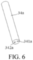
- FIG. 6 is a schematic structural diagram of a tubular support member 34a configured to help assemble the first metal material and the second metal material and promote the first metal material and the second metal material to be insulated from each other when the insulating material layers are not sprayed.
- a first through hole 341a and a second through hole 342a that extend along an axial direction are provided in the tubular support member 34a.
- the first metal material 331 runs through the first through hole 341a
- the second metal material runs through the second through hole 342a. Therefore, the first metal material 331 and the second metal material 332 are respectively held by the first through hole 341a and the second through hole 342a, and are separated and insulated from each other while being fixed and assembled.
- the metal base body 32/32a may further be constructed to include two holes respectively for the first metal material 331 and the second metal material 332 to run through.
- thermocouple that can be configured to measure a temperature is formed by simultaneously connecting the first metal material and the second metal material that are made of different materials to the metal base body, thereby achieving a more accurate temperature measurement effect and enabling production and preparation to be more convenient.
- An embodiment of this application further provides a temperature measurement apparatus that may be configured to measure a temperature, and a structure thereof is shown in FIG. 3 to FIG. 4 .
- the temperature measurement apparatus may include a metal base body 32 that can be constructed to be in a shape of a sheet, a ring, or a column.
- a thermocouple that is capable of measuring a temperature can be formed between the first metal material and the second metal material.
- each of the first metal material 331 and the second metal material 332 is made of a galvanic material such as iron, nickel-chromium alloy, nickel-silicon alloy, nickel-chromium-copper, constant bronze, or iron-chromium alloy.
Landscapes
- Physics & Mathematics (AREA)
- Electromagnetism (AREA)
- Measuring Temperature Or Quantity Of Heat (AREA)
Abstract
Description
- This application claims priority to
Chinese Patent Application No. 202011047354.3, filed with the China National Intellectual Property Administration on September 29, 2020 - Embodiments of this application relate to the field of heat-not-burn cigarette devices of an electromagnetic induction type, and in particular, to a susceptor for an aerosol generation apparatus, an aerosol generation apparatus, and a temperature measurement apparatus.
- Tobacco products (such as cigarettes and cigars) burn tobacco during use to produce tobacco smoke. Attempts are made to replace these tobacco-burning products by manufacturing products that release compounds without burning.
- An example of such a product is a heating apparatus that releases compounds by heating rather than burning materials. For example, the materials may be tobacco or other non-tobacco products. These non-tobacco products may or may not include nicotine. In a known apparatus, temperature monitoring is required in a process of heating a tobacco product. In an example, such a product is attached to a heating component through a temperature sensor, to obtain a temperature of the heating component.
- An embodiment of this application provides an aerosol generation apparatus, configured to heat an aerosol-forming article to generate an aerosol, and including:
- a chamber, configured to receive at least a part of the aerosol-forming article;
- a magnetic field generator, configured to generate a variable magnetic field; and
- a susceptor, configured to be penetrated by the variable magnetic field to generate heat, to heat the aerosol-forming article, where the susceptor includes:
- a sensing part, constructed to at least partially extend in the chamber and including a hollow extending along an axial direction; and
- a metal base body, located in the hollow of the sensing part and abutting against the sensing part, where a first metal material and a second metal material are connected to the metal base body, and the first metal material and the second metal material are made of different materials, to cause a thermocouple configured to sense a temperature of the sensing part to be formed between the first metal material and the second metal material.
- In a preferred implementation, the metal base body is substantially constructed to be coaxial with the sensing part and in a shape of a sheet or a column.
- In a preferred implementation, the susceptor further includes:
a support member, located in the hollow of the sensing part and providing support for the metal base body, to cause the metal base body to abut against the sensing part. - In a preferred implementation, the sensing part includes a pointed end configured to be inserted into the aerosol-forming article and a far end facing away from the pointed end; and
the metal base body includes a first surface close to the pointed end along the axial direction and a second surface facing away from the first surface; and the support member supports the metal base body on the second surface, to cause the first surface to abut against the sensing part. - In a preferred implementation, the second surface is a flat surface extending along a cross-sectional direction of the susceptor.
- In a preferred implementation, the sensing part includes a pointed end configured to be inserted into the aerosol-forming article; and the metal base body includes a first surface close to the pointed end along the axial direction, where the first surface is a flat surface extending along the cross-sectional direction of the susceptor.
- In a preferred implementation, the first metal material and/or the second metal material run through the metal base body along the axial direction.
- In a preferred implementation, the first metal material and/or the second metal material are connected to the first surface of the metal base body.
- In a preferred implementation, the first metal material and/or the second metal material do not protrude from the first surface of the metal base body.
- In a preferred implementation, the support member is constructed to be coaxial with the sensing part and in a shape of a column or a tube.
- In a preferred implementation, a first through hole and a second through hole that are arranged along the axial direction of the susceptor are provided on the support member; and
the first metal material at least partially extends in the first through hole, and the second metal material at least partially extends in the second through hole. - In a preferred implementation, a base part extending to the outside along a radial direction is further arranged in the sensing part, and the susceptor is held in the aerosol generation apparatus through the base part.
- In a preferred implementation, the first metal material and/or the second metal material are constructed to be in shapes of elongated filaments and at least partially run through the sensing part.
- In a preferred implementation, the sensing part and the metal base body are made of the same material.
- An embodiment of this application further provides a susceptor for an aerosol generation apparatus, including: a sensing part, constructed to include a hollow extending along a length direction of the susceptor; and
a metal base body, located in the hollow of the sensing part and abutting against the sensing part, where a first metal material and a second metal material are connected to the metal base body, and the first metal material and the second metal material are made of different materials, to cause a thermocouple configured to sense a temperature of the sensing part to be formed between the first metal material and the second metal material. - An embodiment of this application further provides a temperature measurement apparatus, including a metal base body, where a first metal material and a second metal material are connected to the metal base body, and the first metal material and the second metal material are made of different materials, to cause a thermocouple configured to sense a temperature to be formed between the first metal material and the second metal material.
- In the foregoing aerosol generation apparatus and susceptor, a thermocouple that can be configured to measure a temperature is formed by simultaneously connecting the first metal material and the second metal material that are made of different materials to the metal base body, thereby achieving a more accurate temperature measurement effect.
- One or more embodiments are exemplarily described with reference to the corresponding figures in the accompanying drawings, and the descriptions are not to be construed as limiting the embodiments. Elements in the accompanying drawings that have same reference numerals are represented as similar elements, and unless otherwise particularly stated, the figures in the accompanying drawings are not drawn to scale.
-
FIG. 1 is a schematic structural diagram of an aerosol generation apparatus according to an embodiment; -
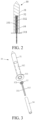
FIG. 2 is a schematic cross-sectional structural diagram of a susceptor inFIG. 1 ; -
FIG. 3 is a schematic exploded view of various parts of the susceptor inFIG. 2 before assembly; -
FIG. 4 is a schematic diagram of welding a first metal material and a second metal material to an upper surface of the metal base body; -
FIG. 5 is a schematic structural diagram of a metal base body according to another embodiment; and -
FIG. 6 is a schematic diagram of a tubular support member provided with two through holes according to another embodiment. - For ease of understanding of this application, this application is described in further detail below with reference to the accompanying drawings and specific implementations.
- An embodiment of this application provides an aerosol generation apparatus and a structure thereof may refer to
FIG. 1 . The apparatus includes: - a chamber, where an aerosol-forming article A is removably received in the chamber;
- an induction coil L, configured to generate a variable magnetic field under an alternating current;
- a
susceptor 30, at least partially extending in the chamber, and configured to be inductively coupled to the induction coil L and be penetrated by the variable magnetic field to generate heat, to heat the aerosol-forming article A such as a cigarette, so that at least one component of the aerosol-forming article A is atomized, thereby forming an aerosol for inhaling; - a
cell 10, being a rechargeable direct-current cell and capable of outputting a direct current; and - a
circuit 20, being connected to therechargeable cell 10 through a suitable current, and configured to convert the direct current outputted by thecell 10 into an alternating current with a suitable frequency and then supply the alternating current to the induction coil L. - According to settings during use of a product, the induction coil L may be a cylindrical induction coil wound into a helical shape, as shown in
FIG. 1 . A radius r of the cylindrical induction coil L wound into the helical shape may range from about 5 mm to about 10 mm, and particularly, the radius r may be about 7 mm. A length of the cylindrical induction coil L wound into the helical shape may range from about 8 mm to about 14 mm, and a quantity of turns of the induction coil L ranges from 8 to 15. Correspondingly, an inner volume may range from about 0.15 cm3 to about 1.10 cm3. - In a more preferred implementation, the frequency of the alternating current supplied by the
circuit 20 to the induction coil L ranges from 80 KHz to 400 KHz; and more specifically, the frequency may range from about 200 KHz to 300 KHz. - In a preferred embodiment, a direct-current supply voltage provided by the
cell 10 ranges from about 2.5 V to about 9.0 V, and an amperage of the direct current that thecell 10 can provide ranges from about 2.5 A to about 20 A. - In a preferred embodiment, the
susceptor 30 is substantially in a shape of a pin or a blade, which is beneficial for the susceptor to be inserted into the aerosol-forming article A. In addition, thesusceptor 30 may be defined with a length of about 12 mm, a width of about 4 mm, and a thickness of about 0.5 mm, and may be made of stainless steel of level 430 (SS430). As an alternative embodiment, thesusceptor 30 may be defined with a length of about 12 mm, a width of about 5 mm, and a thickness of about 0.5 mm, and may be made of stainless steel of level 430 (SS430). In other variant embodiments, thesusceptor 30 may alternatively be constructed to be in a shape of a cylinder. During use, an internal space of the susceptor is used for receiving the aerosol-forming article A and generating the aerosol for inhaling in a manner of heating an outer periphery of the aerosol-forming article A. These susceptors may also be made of stainless steel of level 420 (SS420) and alloy materials (such as permalloy) containing iron and nickel. - In the embodiment shown in
FIG. 1 , the aerosol generation apparatus further includes aholder 40 configured to arrange the induction coil L and thesusceptor 30. Theholder 40 may be made of a high-temperature-resistant non-metal material such as PEEK, ceramic, or the like. In an implementation, the induction coil L is fixed by winding around an outer wall of theholder 40. In addition, as shown inFIG. 1 , a hollow of theholder 40 is in a shape of a tube, and the chamber configured to receive the aerosol-forming article A is formed in a part of a space of the tubular hollow. - In a preferred implementation, to accurately monitor a temperature of the
susceptor 30, a detailed structure of thesusceptor 30 is shown inFIG. 2 and FIG. 3 . The susceptor includes:
asensing part 31, constructed to include a hollow 312 and in a shape of a pin, and configured to be penetrated by the variable magnetic field to generate heat, where an external diameter of the sensing part may generally range from about 1.5 mm to about 3 mm, and the hollow 312 forms an opening at a lower end of thesensing part 31. In an implementation, an extension length of the hollow 312 in thesensing part 31 approximately ranges from one-half to two-thirds of a length of thesensing part 31. An internal diameter of the hollow 312 ranges from 1.0 mm to 2.0 mm, and preferably ranges from 1.2 mm to 1.8 mm. - In an optional implementation, the
sensing part 31 is prepared by using the sensing metal material described above. In a variable implementation, thesensing part 31 is obtained by forming a sensing material coating through electroplating, deposition, and the like on an outer surface of a heat-resistant base material such as ceramic that is in a shape of a pin or in a shape similar to the pin. - The hollow 312 of the
sensing part 31 is arranged with:
ametal base body 32, being substantially in a shape of a ring and being coaxially positioned in the hollow 312 of thesensing part 31, where afirst metal material 331 and asecond metal material 332 are connected to themetal base body 32 in a welding manner or the like. In the implementation, thefirst metal material 331 and thesecond metal material 332 are made of different galvanic materials and are in shapes of elongated filaments or pins, so that a thermocouple configured to measure a temperature can be formed between thefirst metal material 331 and thesecond metal material 332 through themetal base body 32. In an optional implementation, thefirst metal material 331 and thesecond metal material 332 are respectively used as a positive electrode and a negative electrode of the thermocouple, where the positive electrode may be made of a nickel-chromium alloy wire and the negative electrode may be made of a nickel-silicon alloy wire, to form a K-type thermocouple. - According to the preferred implementations shown in
FIG. 3 andFIG. 4 , thefirst metal material 331 and thesecond metal material 332 are welded to a surface of the metal base body after running through an annularmiddle hole 321 of themetal base body 32, thereby forming the thermocouple configured to measure the temperature between the first metal material and the second metal material. In an optional implementation, welding may be performed in a manner of laser welding, resistance welding, argon arc welding, or the like. - Further, in a preferred implementation, the
metal base body 32 is prepared by using a material the same as that of thesensing part 31. In addition, a thickness of themetal base body 32 preferably ranges from 1 mm to 2 mm, so that the metal base body is substantially constructed to be in a shape of a relatively small sheet or a thin sheet. Therefore, heat can be transferred more quickly between the metal base body and thesensing part 31, thereby sensing a temperature of a high-temperature region of thesensing part 31 more accurately. In an optional implementation, the thickness of the metal base body may be increased, so that the metal base body is coaxial with the sensing part and in a shape of a column. - To enable the thermocouple configured to measure the temperature and formed by using the
metal base body 32, thefirst metal material 331, and thesecond metal material 332 to detect the temperature of thesensing part 31 conveniently and accurately and to be arranged in thesensing part 31 stably, thesusceptor 30 further includes:
atubular support member 34, where an upper end of the tubular support member is configured to support themetal base body 32, so that the metal base body can be stably held on or abut against a top inner wall of the hollow 312 of thesensing part 31. - Further, the
tubular support member 34 is made of temperature-resistant ceramic such as zirconia ceramic, alumina ceramic, PEEK, or the like. After being assembled into the hollow 312 of thesensing part 31, thetubular support member 34 is connected and fixed to thesensing part 31 by applying ceramic glue to a gap between the tubular support member and the hollow or arranging a mechanical connection structure such as screw threads or a buckle. In an optional implementation, an external diameter of thetubular support member 34 ranges from 1.0 mm to 2.0 mm, slightly less than the internal diameter of the hollow 312 of thesensing part 31, to enable the tubular support member to be inserted into the hollow. The external diameter of the tubular support member preferably ranges from 1.2 mm to 1.8 mm. A diameter of the ceramic rod is less than a diameter of a center hole of an electromagnetic heating rod, to enable a ceramic rod core to be inserted into the center core of the heating rod. An internal diameter of the annularmiddle hole 321 of thetubular support member 34 ranges from 0.5 mm to 1.2 mm and preferably ranges from 0.6 mm to 1.0 mm, to enable thefirst metal material 331 and thesecond metal material 332 to run through the annular middle hole. - Further, in a preferred implementation, a
base part 311 extending to the outside along the radial direction is further arranged at the lower end of thesensing part 31. Thesusceptor 30 can be supported and fixed through thebase part 311, so that the susceptor is stably held in the aerosol generation apparatus. - Further, in a more preferred implementation, as shown in
FIG. 5 , to maintain flatness of a surface of the thermocouple formed to measure the temperature, so that the thermocouple can stably abuts against the inner wall of the hollow 312 of thesensing part 31, agroove 322a configured to accommodate and weld thefirst metal material 331 and thesecond metal material 332 is provided on an upper surface of ametal base body 32a, where the groove may be formed in a manner of etching, machining, or the like. In the implementation, thefirst metal material 331 and thesecond metal material 332 are welded in thegroove 322a after running through amiddle hole 321a from a lower side of themetal base body 32a. In this way, after preparation, thefirst metal material 331 and thesecond metal material 332 do not protrude from the surface of themetal base body 32a, and therefore, the surface of the metal base body can still be a flat surface, thereby enabling thesensing part 31 to be attached to the inner wall of the hollow 312. - In the preferred implementation shown in the figure, cross sections of the hollow 312 of the
sensing part 31, themetal base body 32/32a, and thetubular support member 34 are in shapes of circles, and may also be in shapes of triangles, squares or polygons in other optional implementations. - Surfaces of the
first metal material 331 and thesecond metal material 332 are sprayed with insulating material layers such as polyimide, to cause the first metal material and the second metal material to be insulated from each other. Alternatively,FIG. 6 is a schematic structural diagram of atubular support member 34a configured to help assemble the first metal material and the second metal material and promote the first metal material and the second metal material to be insulated from each other when the insulating material layers are not sprayed. A first throughhole 341a and a second throughhole 342a that extend along an axial direction are provided in thetubular support member 34a. During assembly, thefirst metal material 331 runs through the first throughhole 341a, and the second metal material runs through the second throughhole 342a. Therefore, thefirst metal material 331 and thesecond metal material 332 are respectively held by the first throughhole 341a and the second throughhole 342a, and are separated and insulated from each other while being fixed and assembled. - Based on the same or similar implementation, the
metal base body 32/32a may further be constructed to include two holes respectively for thefirst metal material 331 and thesecond metal material 332 to run through. - In the foregoing aerosol generation apparatus and susceptor, a thermocouple that can be configured to measure a temperature is formed by simultaneously connecting the first metal material and the second metal material that are made of different materials to the metal base body, thereby achieving a more accurate temperature measurement effect and enabling production and preparation to be more convenient.
- An embodiment of this application further provides a temperature measurement apparatus that may be configured to measure a temperature, and a structure thereof is shown in
FIG. 3 to FIG. 4 . The temperature measurement apparatus may include ametal base body 32 that can be constructed to be in a shape of a sheet, a ring, or a column. By connecting afirst metal material 331 and asecond metal material 332 that are made of different materials to themetal base body 32 in a manner of welding or the like, a thermocouple that is capable of measuring a temperature can be formed between the first metal material and the second metal material. In an optional implementation, each of thefirst metal material 331 and thesecond metal material 332 is made of a galvanic material such as iron, nickel-chromium alloy, nickel-silicon alloy, nickel-chromium-copper, constant bronze, or iron-chromium alloy. - It should be noted that, the specification of this application and the accompanying drawings thereof illustrate preferred embodiments of the present invention, but this application is not limited to the embodiments described in the specification. Further, a person of ordinary skill in the art may make improvements or variations according to the foregoing description, and such improvements and variations shall all fall within the protection scope of the appended claims of the present invention.
Claims (16)
- An aerosol generation apparatus, configured to heat an aerosol-forming article to generate an aerosol, and comprising:a chamber, configured to receive the aerosol-forming article;a magnetic field generator, configured to generate a variable magnetic field; anda susceptor, configured to be penetrated by the variable magnetic field to generate heat, to heat the aerosol-forming article, wherein the susceptor comprises:a sensing part, constructed to at least partially extend in the chamber and comprising a hollow extending along an axial direction; anda metal base body, located in the hollow of the sensing part and abutting against the sensing part, wherein a first metal material and a second metal material are connected to the metal base body, and the first metal material and the second metal material are made of different materials, to cause a thermocouple configured to sense a temperature of the sensing part to be formed between the first metal material and the second metal material.
- The aerosol generation apparatus according to claim 1, wherein the metal base body is substantially constructed to be coaxial with the sensing part and in a shape of a sheet, a column, or a ring.
- The aerosol generation apparatus according to claim 1 or 2, wherein the susceptor further comprises:
a support member, located in the hollow of the sensing part and providing support for the metal base body, to cause the metal base body to abut against the sensing part. - The aerosol generation apparatus according to claim 3, wherein the sensing part comprises a pointed end configured to be inserted into the aerosol-forming article and a far end facing away from the pointed end; and
the metal base body comprises a first surface close to the pointed end along the axial direction and a second surface facing away from the first surface; and the support member supports the metal base body on the second surface, to cause the first surface to abut against the sensing part. - The aerosol generation apparatus according to claim 4, wherein the second surface is a flat surface extending along a cross-sectional direction of the susceptor.
- The aerosol generation apparatus according to claim 1 or 2, wherein the sensing part comprises a pointed end configured to be inserted into the aerosol-forming article; and the metal base body comprises a first surface close to the pointed end along the axial direction, wherein
the first surface is a flat surface extending along a cross-sectional direction of the susceptor. - The aerosol generation apparatus according to claim 4, wherein the first metal material and/or the second metal material run through the metal base body along the axial direction.
- The aerosol generation apparatus according to claim 4, wherein the first metal material and/or the second metal material are connected to the first surface of the metal base body.
- The aerosol generation apparatus according to claim 4, wherein the first metal material and/or the second metal material do not protrude from the first surface of the metal base body.
- The aerosol generation apparatus according to claim 3, wherein the support member is constructed to be coaxial with the sensing part and in a shape of a column or a tube.
- The aerosol generation apparatus according to claim 3, wherein a first through hole and a second through hole that are arranged along the axial direction of the susceptor are provided on the support member; and
the first metal material at least partially extends in the first through hole, and the second metal material at least partially extends in the second through hole. - The aerosol generation apparatus according to claim 1 or 2, wherein a base part extending to the outside along a radial direction is further arranged in the sensing part, and the susceptor is held in the aerosol generation apparatus through the base part.
- The aerosol generation apparatus according to claim 1 or 2, wherein the first metal material and/or the second metal material are constructed to be in shapes of elongated filaments and at least partially run through the sensing part.
- The aerosol generation apparatus according to claim 1 or 2, wherein the sensing part and the metal base body are made of the same material.
- A susceptor for an aerosol generation apparatus, comprising: a sensing part, constructed to comprise a hollow extending along a length direction of the susceptor; and
a metal base body, located in the hollow of the sensing part and abutting against the sensing part, wherein a first metal material and a second metal material are connected to the metal base body, and the first metal material and the second metal material are made of different materials, to cause a thermocouple configured to sense a temperature of the sensing part to be formed between the first metal material and the second metal material. - A temperature measurement apparatus, comprising a metal base body, wherein a first metal material and a second metal material are connected to the metal base body, and the first metal material and the second metal material are made of different materials, to cause a thermocouple configured to sense a temperature to be formed between the first metal material and the second metal material.
Applications Claiming Priority (2)
| Application Number | Priority Date | Filing Date | Title |
|---|---|---|---|
| CN202011047354.3A CN114304745A (en) | 2020-09-29 | 2020-09-29 | Susceptor for aerosol-generating device, aerosol-generating device and temperature measuring device |
| PCT/CN2021/121782 WO2022068890A1 (en) | 2020-09-29 | 2021-09-29 | Sensor for aerosol generation apparatus, aerosol generation apparatus and temperature measurement apparatus |
Publications (2)
| Publication Number | Publication Date |
|---|---|
| EP4223161A1 true EP4223161A1 (en) | 2023-08-09 |
| EP4223161A4 EP4223161A4 (en) | 2024-03-20 |
Family
ID=80951209
Family Applications (1)
| Application Number | Title | Priority Date | Filing Date |
|---|---|---|---|
| EP21874545.3A Pending EP4223161A4 (en) | 2020-09-29 | 2021-09-29 | SENSOR FOR AEROSOL GENERATION DEVICE, AEROSOL GENERATION DEVICE AND TEMPERATURE MEASURING DEVICE |
Country Status (4)
| Country | Link |
|---|---|
| US (1) | US20230363463A1 (en) |
| EP (1) | EP4223161A4 (en) |
| CN (1) | CN114304745A (en) |
| WO (1) | WO2022068890A1 (en) |
Families Citing this family (2)
| Publication number | Priority date | Publication date | Assignee | Title |
|---|---|---|---|---|
| CN117356755A (en) * | 2022-06-29 | 2024-01-09 | 云南中烟工业有限责任公司 | Method for producing aerosol-generating products and aerosol-generating products |
| CN115088878A (en) * | 2022-07-05 | 2022-09-23 | 深圳市吉迩科技有限公司 | Electronic atomization device and aerosol generating device suitable for HNB |
Family Cites Families (14)
| Publication number | Priority date | Publication date | Assignee | Title |
|---|---|---|---|---|
| IT1393070B1 (en) * | 2008-10-24 | 2012-04-11 | Worgas Bruciatori Srl | SPECIAL THERMOCOUPLE FOR BURNERS |
| CN105806504A (en) * | 2016-03-30 | 2016-07-27 | 宁波艾克威特智能科技有限公司 | High-temperature-resistant cheap metal armored thermocouple and manufacturing method thereof |
| WO2019021119A1 (en) * | 2017-07-25 | 2019-01-31 | Philip Morris Products S.A. | Heat transfer adaptor for aerosol generating device |
| CN108414106B (en) * | 2018-02-08 | 2019-07-12 | 北京航空航天大学 | A fast-response temperature measuring thermocouple for casting molds |
| CN108617042A (en) * | 2018-07-05 | 2018-10-02 | 湖北中烟工业有限责任公司 | A kind of smoking apparatus of induced inside heating |
| CN110169594A (en) * | 2018-12-25 | 2019-08-27 | 惠州市沛格斯科技有限公司 | Heating module, controllable heating module and electronic smoking set |
| KR102253046B1 (en) * | 2019-03-05 | 2021-05-17 | 주식회사 케이티앤지 | Aerosol generating device and system, and manufacturing method of the aerosol generating device |
| AU2020233969A1 (en) * | 2019-03-11 | 2021-10-07 | Nicoventures Trading Limited | Aerosol provision device |
| CN211153806U (en) * | 2019-08-21 | 2020-08-04 | 珠海惠友电子有限公司 | Temperature measurement pottery heating rod and electron cigarette for electronic cigarette are not burnt in heating |
| CN110477461A (en) * | 2019-08-23 | 2019-11-22 | 惠州市沛格斯科技有限公司 | Heating components and electronic cigarettes |
| CN110810930B (en) * | 2019-11-25 | 2024-12-27 | 惠州市沛格斯科技有限公司 | Electronic smoking equipment |
| CN111418910A (en) * | 2020-03-16 | 2020-07-17 | 深圳市吉迩科技有限公司 | Aerosol generating device, generating system and aerosol generating method |
| WO2021244584A1 (en) * | 2020-06-02 | 2021-12-09 | 深圳市合元科技有限公司 | Aerosol generating device and susceptor therefor |
| CN212464914U (en) * | 2020-09-29 | 2021-02-05 | 深圳市合元科技有限公司 | Susceptor for aerosol-generating device, aerosol-generating device and temperature measuring device |
-
2020
- 2020-09-29 CN CN202011047354.3A patent/CN114304745A/en active Pending
-
2021
- 2021-09-29 US US18/029,357 patent/US20230363463A1/en active Pending
- 2021-09-29 EP EP21874545.3A patent/EP4223161A4/en active Pending
- 2021-09-29 WO PCT/CN2021/121782 patent/WO2022068890A1/en not_active Ceased
Also Published As
| Publication number | Publication date |
|---|---|
| CN114304745A (en) | 2022-04-12 |
| WO2022068890A1 (en) | 2022-04-07 |
| US20230363463A1 (en) | 2023-11-16 |
| EP4223161A4 (en) | 2024-03-20 |
Similar Documents
| Publication | Publication Date | Title |
|---|---|---|
| CN212464914U (en) | Susceptor for aerosol-generating device, aerosol-generating device and temperature measuring device | |
| CN212852498U (en) | Sensor for aerosol-generating device, aerosol-generating device | |
| US12446625B2 (en) | Vapor generation device and susceptor | |
| KR102363814B1 (en) | Device for heating smokeable material | |
| US20220030949A1 (en) | Inductively heatable aerosol-generating article comprising an aerosol-forming substrate and a susceptor assembly | |
| US20220030946A1 (en) | Inductive heating assembly for inductive heating of an aerosol-forming substrate | |
| US20220046991A1 (en) | Susceptor assembly for inductively heating an aerosol-forming substrate | |
| US20230284701A1 (en) | Vapor-generation device and susceptor for vapor-generation device | |
| KR20210061409A (en) | Induction heating aerosol generating device including susceptor assembly | |
| US20230363463A1 (en) | Susceptor for vapor generation apparatus, vapor generation apparatus, and temperature measurement apparatus | |
| KR20210064307A (en) | Method for inductive heating of heating assemblies and aerosol-forming substrates | |
| EP4430968A1 (en) | Aerosol generating device, and heater of aerosol generating device | |
| CN215347073U (en) | Gas mist generating device and heater for gas mist generating device | |
| US12193506B2 (en) | Aerosol generation device and susceptor | |
| US20240341361A1 (en) | Aerosol generation device | |
| WO2023051729A1 (en) | Aerosol generating device and heater for aerosol generating device | |
| EP3989754A1 (en) | Aerosol provision device | |
| CN215684868U (en) | Gas mist generating device and heater for gas mist generating device | |
| CN216961533U (en) | Gas mist generating device and heater for gas mist generating device | |
| CN215347064U (en) | Aerosol-generating device and susceptor for aerosol-generating device | |
| CN213344351U (en) | Aerosol generating device and sensor | |
| CN215347072U (en) | Aerosol-generating device and susceptor for aerosol-generating device | |
| CN113576048A (en) | Susceptor for aerosol-generating device, aerosol-generating device | |
| US20240008540A1 (en) | Heater for use in aerosol generation device, and aerosol generation device | |
| CN215347061U (en) | Heater and aerosol generating device |
Legal Events
| Date | Code | Title | Description |
|---|---|---|---|
| STAA | Information on the status of an ep patent application or granted ep patent |
Free format text: STATUS: THE INTERNATIONAL PUBLICATION HAS BEEN MADE |
|
| PUAI | Public reference made under article 153(3) epc to a published international application that has entered the european phase |
Free format text: ORIGINAL CODE: 0009012 |
|
| STAA | Information on the status of an ep patent application or granted ep patent |
Free format text: STATUS: REQUEST FOR EXAMINATION WAS MADE |
|
| 17P | Request for examination filed |
Effective date: 20230302 |
|
| AK | Designated contracting states |
Kind code of ref document: A1 Designated state(s): AL AT BE BG CH CY CZ DE DK EE ES FI FR GB GR HR HU IE IS IT LI LT LU LV MC MK MT NL NO PL PT RO RS SE SI SK SM TR |
|
| DAV | Request for validation of the european patent (deleted) | ||
| DAX | Request for extension of the european patent (deleted) | ||
| STAA | Information on the status of an ep patent application or granted ep patent |
Free format text: STATUS: EXAMINATION IS IN PROGRESS |
|
| A4 | Supplementary search report drawn up and despatched |
Effective date: 20240219 |
|
| RIC1 | Information provided on ipc code assigned before grant |
Ipc: A24F 40/465 20200101AFI20240213BHEP |
|
| 17Q | First examination report despatched |
Effective date: 20240304 |