EP4221898B1 - Annular centrifugal extractor and a process for the same - Google Patents
Annular centrifugal extractor and a process for the same Download PDFInfo
- Publication number
- EP4221898B1 EP4221898B1 EP21851859.5A EP21851859A EP4221898B1 EP 4221898 B1 EP4221898 B1 EP 4221898B1 EP 21851859 A EP21851859 A EP 21851859A EP 4221898 B1 EP4221898 B1 EP 4221898B1
- Authority
- EP
- European Patent Office
- Prior art keywords
- bowl
- rotating cylinder
- phase
- solid particles
- solid
- Prior art date
- Legal status (The legal status is an assumption and is not a legal conclusion. Google has not performed a legal analysis and makes no representation as to the accuracy of the status listed.)
- Active
Links
Images





Classifications
-
- B—PERFORMING OPERATIONS; TRANSPORTING
- B04—CENTRIFUGAL APPARATUS OR MACHINES FOR CARRYING-OUT PHYSICAL OR CHEMICAL PROCESSES
- B04B—CENTRIFUGES
- B04B1/00—Centrifuges with rotary bowls provided with solid jackets for separating predominantly liquid mixtures with or without solid particles
- B04B1/02—Centrifuges with rotary bowls provided with solid jackets for separating predominantly liquid mixtures with or without solid particles without inserted separating walls
-
- B—PERFORMING OPERATIONS; TRANSPORTING
- B01—PHYSICAL OR CHEMICAL PROCESSES OR APPARATUS IN GENERAL
- B01D—SEPARATION
- B01D11/00—Solvent extraction
- B01D11/04—Solvent extraction of solutions which are liquid
- B01D11/0446—Juxtaposition of mixers-settlers
- B01D11/0457—Juxtaposition of mixers-settlers comprising rotating mechanisms, e.g. mixers, mixing pumps
-
- B—PERFORMING OPERATIONS; TRANSPORTING
- B01—PHYSICAL OR CHEMICAL PROCESSES OR APPARATUS IN GENERAL
- B01D—SEPARATION
- B01D11/00—Solvent extraction
- B01D11/04—Solvent extraction of solutions which are liquid
- B01D11/0476—Moving receptacles, e.g. rotating receptacles
- B01D11/048—Mixing by counter-current streams provoked by centrifugal force, in rotating coils or in other rotating spaces
-
- B—PERFORMING OPERATIONS; TRANSPORTING
- B04—CENTRIFUGAL APPARATUS OR MACHINES FOR CARRYING-OUT PHYSICAL OR CHEMICAL PROCESSES
- B04B—CENTRIFUGES
- B04B11/00—Feeding, charging, or discharging bowls
- B04B11/02—Continuous feeding or discharging; Control arrangements therefor
Definitions
- the present invention relates to an Annular Centrifugal Extractor with Solid Separation Part to Separate Solid Particles present in Solvent Extraction Fluid and a process for the same in a spent nuclear fuel reprocessing industry or in any other solvent extraction (solid particles are encountered) process.
- Solutions generated from dissolution of nuclear fuel contain unknown quantities of undissolved solids. A majority of these solids are removed via various methods of filtration/separation. Smaller particles are expected to carry through to downstream solvent extraction processes and equipment. Solids/precipitates resulting from mechanical or chemical upsets are another potential area of concern. Solids accumulate uniformly along the inside diameter of the rotor cylinder from the inlet orifice to the heavy phase weir. Over time, these solids form a layer on the inner wall that is sufficiently thick to interfere with the flow of the heavy phase through the heavy-phase underflow slots at the top of the separating zone.
- CIP clean-in-place
- nozzles are employed to remove the solid particles settle inside the ACE during solvent extraction.
- Spent nuclear fuel dissolution solution contains un-dissolved solid particles.
- the smaller particles are expected to carry over with the solution and partake in the solvent extraction operation. Therefore, high speed centrifuge is employed in fast breeder reprocessing plant to separate un-dissolved fine particles from the solution.
- the failure or malfunction of the aforementioned centrifuge leads to carry over of particles in the process liquid.
- new solid/precipitates may be generated through mechanical or chemical process upsets.
- the solid particles settle inside the rotating bowl due to high centrifugal force during solvent extraction which forms a cake-like structure on inner wall of the ACE. As a result it leads to a reduction in phase separation capacity or complete chock inside liquid-liquid separator (rotating bowl).
- US 5 908 376 A discloses a self-cleaning rotor assembly for a centrifugal Separator can be thoroughly cleaned of accumulated solids without disassembly of the separator.
- the rotor assembly comprises a fully welded, enclosed rotor body.
- the rotor assembly has a double-ended, hollow axial shaft.
- the bottom end of the axial shaft extends through the separator housing and has a high pressure fluid coupling.
- a plurality of spray nozzles are fitted to the axial shaft within the rotor body.
- the spray nozzles are arranged to spray a washing fluid radially onto the interior surfaces of the rotor.
- the interior volume of the rotor is divided into a plurality of chambers by a corresponding plurality of axial vanes. At least one nozzle is disposed within each of the chambers.
- an object of the invention is to propose an annular centrifugal extractor with solid separation part to separate solid particles present in solvent extraction fluid and a process for the same which is capable of eliminating the drawbacks of the prior art.
- Another object of the invention is to propose an annular centrifugal extractor with solid separation part to separate solid particles present in solvent extraction fluid and a process for the same which does not require any additional system for further processing of separated solid particle.
- Yet another object of the invention is to propose an annular centrifugal extractor with solid separation part to separate solid particles present in solvent extraction fluid and a process for the same which does not require additional dechoking facility.
- a still another object of the invention is to propose an annular centrifugal extractor with solid separation part to separate solid particles present in solvent extraction fluid and a process for the same which enhances ACE operating life.
- a still further object of the invention is to propose an annular centrifugal extractor with solid separation part to separate solid particles present in solvent extraction fluid and a process for the same which ensures minimum maintenance cost.
- a further object of the invention is to propose an annular centrifugal extractor with solid separation part to separate solid particles present in solvent extraction fluid and a process for the same which facilitates for sending separated solid particle for further processing or waste management facility.
- the present invention provides an annular centrifugal extractor (ACE) with solid separation part having the features of independent claim 1 and a process to separate solid particles present in solvent extraction fluid in an annular centrifugal extractor (ACE) as claimed in independent claim 4.
- ACE annular centrifugal extractor
- a solid separation part is attached to the rotating bowl of ACE in such a way that solid partiles settle inside the separation part.
- Centrifugal extractor with solid separation part is designed and fabricated. Choking experiments were conducted in centrifugal extractor (CE) with and without solid separation part in bowls. Experimental results showed that CE with solid separation part can separate or hold solid particles without losing of flooding throughput. Amount of solid settled inside bowl with solid separation can be physically inspected due to threaded joint and necessary action may be taken before start-up. The removed solid particles having high radioactivity can be sent to waste management plant as a solid waste.
- ACE Annular centrifugal extractor is widely used in solvent extraction operations and offers some advantages and disadvantages.
- ACE is a candid candidate for the fast breeder reprocessing application.
- One of its main disadvantages is very sensitive to the solid particles which drastically affect the hydrodynamic operation by settling inside the rotating bowl due to high centrifugal acceleration.
- ACE is operational in CORAL facility for more than two decades to separate uranium and plutonium from fast breeder reactor spent nuclear fuel. The solid particles are frequently encountered during nuclear reprocessing.
- a new ACE coupled with solid centrifuge is developed. The new design can be operated in existing CORAL stationary bowl. It is the very first time that the solid separating centrifuge is coupled with centrifugal extractor as a single unit.
- Novel solid separating centrifugal extractor contains two parts: (i) upper part act as a liquid-liquid separator to separate aqueous and organic solution used in solvent extraction operation and (ii) bottom part act as a solid separator to separate solid particle present in solvent extraction liquids. Diameter and height of the centrifugal extractor bowl with solid separation part is decided based on existing 30 mm diameter centrifugal extractor stationary bowl.
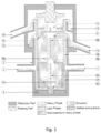
- the annular centrifugal extractor (ACE) with solid separation part in accordance with the invention is shown in Fig. 1 .
- the solid separating centrifuge is coupled with the existing annular centrifugal extractor bowl to handle the solid particle during solvent extraction operation.
- Bowl (4A & 4B) diameter and height are fixed based on process parameters such as (i) amount of liquid handled per unit time (L/h), (ii) particle size and (iii) amount of particle present in the process liquid (gm/litre) etc.
- the stationary bowl (3) diameter and height is fixed.
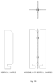
- Vertical baffles height (8A & 8B) is always equal to its corresponding bowl (4A & 4B) height. Its width is equal to half of the bowl diameter.
- the 36mm solid separating ACE bowl is developed to make it suitable for the existing plant condition when the bowls used are of the following dimensions:
- Novel solid separating annular centrifugal extractor contains two rotating bowl parts (i) upper rotating part (4B) act as a liquid-liquid separator to separate aqueous and organic solution used in solvent extraction operation and (ii) bottom rotating part (4A) act as a solid separator to separate solid particle present in solvent extraction/process liquid.
- Bottom (4A) rotating cylinder/bowl (particle/solid separating rotor) is coupled with (4B) rotating cylinder/bowl (liquid/liquid separating rotor) by threaded joint (or any other joint).
- the said ACE consists with solid separation part of a heavy phase inlet (1) for feeding heavy phase and light phase inlet (2) for feeding light phase of material into the ACE, a stationary cylinder/bowl (3), a rotating cylinder (4A) which is a particle / solid separating rotor, a rotating cylinder (4B) which is liquid/liquid separating rotor, radial baffles (5) on the stationary bottom plate, a central opening (6A) for rotating cylinder (4A), a central opening (6B) for rotating cylinder (4B), a deflecting baffle (7A) in the rotor (4A), a deflecting baffle (7B) in the rotor (4B), light phase weir (9), under flow region for heavy phase (10), heavy phase weir (11), light phase collection chamber (12), heavy phase collection chamber (13), light phase outlet part (14) and heavy phase outlet part (15).
- the stationary bowl (3) has a cover at the top, called as seating block (16) which supports the motor/drive to rotate the two threadedly joined bowls
- Bottom baffle Main function of bottom baffle is to break the vortex formation and provided in the bottom region which are either attached to the base of the outer cylinder or to the bottom of the rotating cylinder. Dispersion with solid particles entering inside the rotating bowl (particle/solid separating rotor, 4A) is deflected towards the wall of the rotating cylinder by deflecting baffle (7A) to enhance the centrifugal sedimentation of solid particles. Solid particles gets separated inside particle/solid separating rotor and dispersion flows from bottom to top inside the rotating bowl (and it is confined inside the chambers (four to eight numbers) by vertical baffles (8A).
- the rotating cylinder imparts a rigid body rotation to the dispersion with solid particles and creates vertically cylindrical free surface of liquid and it is coaxial with the axis of rotation because of high centrifugal acceleration 'a'.
- the central portion is occupied by air.
- the solid particles entering at the bottom gets separated as it moves upwards.
- the sedimentation rate of solid particles depends upon density difference between solid particle and mixed phase, viscosity of mixed phase, particle size distribution, and settling velocity of particle under centrifugal acceleration (r ⁇ 2 ). For complete separation of solid particles, adequate height and diameter are provided for a given level of centrifugal acceleration.
- Dispersion (free from solid particles) entering inside the upper rotating bowl (4B, inside liquid/liquid separating rotor) through orifice (6B) is deflected towards the wall of the rotating cylinder by deflecting baffle (7B) to enhance the centrifugal separation of heavy and light phases.
- Dispersion phase gets separated and also flows from bottom to top inside the rotating bowl and it is confined inside the chambers (four to eight numbers) by vertical baffles (8B).
- the rotating cylinder imparts a rigid body rotation to the liquid and creates vertically cylindrical free surface of liquid and it is coaxial with the axis of rotation because of high centrifugal acceleration 'a'. The central portion is occupied by air.
- the dispersion entering at the bottom gets separated as it moves upwards.
- the separation rate of dispersed phase depends upon density difference between continuous and dispersed phase, viscosity of continuous phase, drop size distribution, settling velocity of dispersed phase under centrifugal acceleration (r ⁇ 2 ) and coalescing behavior of the dispersed phase.
- r ⁇ 2 settling velocity of dispersed phase under centrifugal acceleration
- coalescing behavior of the dispersed phase For complete separation (which is considered to be a latest advantage of ACEs) of dispersion, adequate height and diameter are provided for a given level of centrifugal acceleration.
- Separated lighter phase flow over light phase weir (9) and it is thrown out in to lighter phase collection chamber (12) located at stationary bowl.
- heavy phase flows over heave phase weir (11) via under flow (10) and it is thrown out in to heavy phase collection chamber (13) located above lighter phase collection chamber at stationary bowl.
- both heavy phase and light phase comes out or flows in to adjacent stages through light phase outlet (14) and heavy phase outlet (15).
Landscapes
- Chemical & Material Sciences (AREA)
- Chemical Kinetics & Catalysis (AREA)
- Centrifugal Separators (AREA)
- Extraction Or Liquid Replacement (AREA)
Description
- Annular Centrifugal Extractor with Solid Separation Part to Separate Solid Particles Present in Solvent Extraction Fluid and a process for the same.
- The present invention relates to an Annular Centrifugal Extractor with Solid Separation Part to Separate Solid Particles present in Solvent Extraction Fluid and a process for the same in a spent nuclear fuel reprocessing industry or in any other solvent extraction (solid particles are encountered) process.
- The complexities of high radiation damage to solvent and its leads to solvent degradation and necessitate the need for fast contactors (short residence time) like annular centrifugal extractors (ACE) and is currently being used in fast breeder reprocessing (FBR) spent nuclear fuel reprocessing.
- Solutions generated from dissolution of nuclear fuel contain unknown quantities of undissolved solids. A majority of these solids are removed via various methods of filtration/separation. Smaller particles are expected to carry through to downstream solvent extraction processes and equipment. Solids/precipitates resulting from mechanical or chemical upsets are another potential area of concern. Solids accumulate uniformly along the inside diameter of the rotor cylinder from the inlet orifice to the heavy phase weir. Over time, these solids form a layer on the inner wall that is sufficiently thick to interfere with the flow of the heavy phase through the heavy-phase underflow slots at the top of the separating zone.
- To solve above mentioned problem a clean-in-place (CIP) rotor is as part of the ACE unit has been reported in the literature so far. A series of high pressure spray nozzles are mounted on a hollow shaft that connected to the bottom plate to the upper rotor assembly.
- These nozzles are employed to remove the solid particles settle inside the ACE during solvent extraction.
- The drawbacks associated with the prior art stated above are as follows:
- a. High pressure system is not advisable inside the radioactive shielded cell where negative pressure is maintained to contain the radioactivity with in cell volume. In case of solution leakage, accumulated aqueous solution can be unsafe for nuclear criticality.
- b. Insertion of spray nozzles add complexity in the manufacturing of ACE which requires high precession manufacturing technique for dynamic balancing of small rotating bowl. The technique increases the manufacturing cost.
- c. Liquid may flow through the solid collection pipe which is attached with stationary bowl during normal operation. Hence, to avoid the liquid flow, ACE requires another system integrated to it. The additional system to contain mixed phase inside the stationary bowl (mixing zone) for each stage in ACE cascade.
- d. The micron sized solid particles collected inside the stationary bowl may settle inside the downstream of solid handling pipe line. It requires additional dechoking system or process to handle the situation.
- e. To process or handle the separated radioactive solid particle is a major concern.
- Spent nuclear fuel dissolution solution contains un-dissolved solid particles. The smaller particles are expected to carry over with the solution and partake in the solvent extraction operation. Therefore, high speed centrifuge is employed in fast breeder reprocessing plant to separate un-dissolved fine particles from the solution. The failure or malfunction of the aforementioned centrifuge leads to carry over of particles in the process liquid. In addition, new solid/precipitates may be generated through mechanical or chemical process upsets. The solid particles settle inside the rotating bowl due to high centrifugal force during solvent extraction which forms a cake-like structure on inner wall of the ACE. As a result it leads to a reduction in phase separation capacity or complete chock inside liquid-liquid separator (rotating bowl).
-
US 5 908 376 A discloses a self-cleaning rotor assembly for a centrifugal Separator can be thoroughly cleaned of accumulated solids without disassembly of the separator. The rotor assembly comprises a fully welded, enclosed rotor body. The rotor assembly has a double-ended, hollow axial shaft. The bottom end of the axial shaft extends through the separator housing and has a high pressure fluid coupling. A plurality of spray nozzles are fitted to the axial shaft within the rotor body. The spray nozzles are arranged to spray a washing fluid radially onto the interior surfaces of the rotor. The interior volume of the rotor is divided into a plurality of chambers by a corresponding plurality of axial vanes. At least one nozzle is disposed within each of the chambers. - TAMHANE T V et al.: "Performance of annular centrifugal extractors: CFD simulation of flow pattern, axial mixing and extraction with chemical reaction", CHEMICAL ENGINEERING SCIENCE, OXFORD, GB, vol 110, 23 August 2013, pages 134-143, disclose an annular centrifugal extractor (ACE) having the features of the preamble of independent claim 1 and a process of separating a dispersion of two immiscible liquids using the ACE.
- Therefore an object of the invention is to propose an annular centrifugal extractor with solid separation part to separate solid particles present in solvent extraction fluid and a process for the same which is capable of eliminating the drawbacks of the prior art.
- Another object of the invention is to propose an annular centrifugal extractor with solid separation part to separate solid particles present in solvent extraction fluid and a process for the same which does not require any additional system for further processing of separated solid particle.
- Yet another object of the invention is to propose an annular centrifugal extractor with solid separation part to separate solid particles present in solvent extraction fluid and a process for the same which does not require additional dechoking facility.
- A still another object of the invention is to propose an annular centrifugal extractor with solid separation part to separate solid particles present in solvent extraction fluid and a process for the same which enhances ACE operating life.
- A still further object of the invention is to propose an annular centrifugal extractor with solid separation part to separate solid particles present in solvent extraction fluid and a process for the same which ensures minimum maintenance cost.
- A further object of the invention is to propose an annular centrifugal extractor with solid separation part to separate solid particles present in solvent extraction fluid and a process for the same which facilitates for sending separated solid particle for further processing or waste management facility.
- In order to meet at least some of the objects mentioned above, the present invention provides an annular centrifugal extractor (ACE) with solid separation part having the features of independent claim 1 and a process to separate solid particles present in solvent extraction fluid in an annular centrifugal extractor (ACE) as claimed in independent claim 4. Especially preferred embodiments of the present invention are subject-matter of the dependent claims.
- In order to remove solid particles from the solution, a solid separation part is attached to the rotating bowl of ACE in such a way that solid partiles settle inside the separation part.
- Centrifugal extractor with solid separation part is designed and fabricated. Choking experiments were conducted in centrifugal extractor (CE) with and without solid separation part in bowls. Experimental results showed that CE with solid separation part can separate or hold solid particles without losing of flooding throughput. Amount of solid settled inside bowl with solid separation can be physically inspected due to threaded joint and necessary action may be taken before start-up. The removed solid particles having high radioactivity can be sent to waste management plant as a solid waste.
- Annular centrifugal extractor is widely used in solvent extraction operations and offers some advantages and disadvantages. ACE is a candid candidate for the fast breeder reprocessing application. One of its main disadvantages is very sensitive to the solid particles which drastically affect the hydrodynamic operation by settling inside the rotating bowl due to high centrifugal acceleration. ACE is operational in CORAL facility for more than two decades to separate uranium and plutonium from fast breeder reactor spent nuclear fuel. The solid particles are frequently encountered during nuclear reprocessing. In order to handle solid particles, a new ACE coupled with solid centrifuge is developed. The new design can be operated in existing CORAL stationary bowl. It is the very first time that the solid separating centrifuge is coupled with centrifugal extractor as a single unit.
- Novel solid separating centrifugal extractor contains two parts: (i) upper part act as a liquid-liquid separator to separate aqueous and organic solution used in solvent extraction operation and (ii) bottom part act as a solid separator to separate solid particle present in solvent extraction liquids. Diameter and height of the centrifugal extractor bowl with solid separation part is decided based on existing 30 mm diameter centrifugal extractor stationary bowl.
- The hydrodynamic and mass transfer experiments have been carried out and the experimental data were compared with conventional centrifugal extractor bowl. It was evident from the experimental results that the performance of ACE with solid separation part is on par with the conventional ACE except at flooding throughput.
- There is no apparent disadvantage of integrating solid-collection part to bottom of centrifugal extractor rotary bowl. Mass transfer efficiency (and recovery) is not affected by this change.
-
- Fig. 1 -
- shows schematic view of the annular centrifugal extractor with solid separation part according to the invention
- Fig. 2 -
- shows schematic view of single stage ACE (without solid separation part) including drive and its support
- Fig. 3 -
- shows details of bowl diameter and height according to invention
- Fig. 4 -
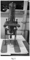
- shows a photographic view of single stage setup during assembly
- Fig. 5 -
- shows a photographic view of single stage setup assembled condition
- Fig. 6 -
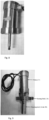
- shows a photographic view of seating block (16) placed above the stationary bowl (3) to support the drive
- Fig. 7 -
- shows a photographic view of rotating bowl (4A & 4B)
- Fig. 8 -
- shows a photographic view of motor/drive placed above the seating block (16) to rotate the ACE bowl (4A & 4B)
- Fig. 9 -
- shows a photographic view of complete assembly of motor (17), seating block (16) and rotating bowl (4A & 4B)
- Fig. 10 -
- shows a photographic view of single stage stationary bowl (3) including pipe inlets and drain line
- Fig. 11 -
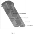
- shows a 3D schematic sectioned view of rotating bowl (4A & 4B) with vertical baffles (8A & 8B) and deflecting baffle (7A & 7B)
- Fig. 12 -
- shows a photographic sectional view of rotating bowl without solid separation part
- Fig. 13 -
- shows schematic view of vertical baffles
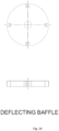
- Fig. 14 -
- shows schematic view of deflecting baffle
- The annular centrifugal extractor (ACE) with solid separation part in accordance with the invention is shown in
Fig. 1 . The solid separating centrifuge is coupled with the existing annular centrifugal extractor bowl to handle the solid particle during solvent extraction operation. Bowl (4A & 4B) diameter and height are fixed based on process parameters such as (i) amount of liquid handled per unit time (L/h), (ii) particle size and (iii) amount of particle present in the process liquid (gm/litre) etc. Based on the diameter and height of the 4A & 4B bowl, the stationary bowl (3) diameter and height is fixed. Vertical baffles height (8A & 8B) is always equal to its corresponding bowl (4A & 4B) height. Its width is equal to half of the bowl diameter. As per plant requirements, the dimensions can be changed. According to present invention the 36mm solid separating ACE bowl is developed to make it suitable for the existing plant condition when the bowls used are of the following dimensions: - 1. 4A bowl: Diameter = 36 mm & Height = 34 mm
- 2. 4B bowl: Diameter = 36 mm & Height = 33.5 mm
- 3. Stationary bowl (3): Diameter = 50 mm & Height = 78.5 mm
- 4. Deflecting baffle (7A, 7B): Diameter = 26 mm & Height/Thickness = 3 mm
- 5. 8A Vertical baffles: Height = 34 mm & width = 18 mm
- 6. 8B Vertical baffles: Height = 33.5 mm & width = 18 mm
- Novel solid separating annular centrifugal extractor contains two rotating bowl parts (i) upper rotating part (4B) act as a liquid-liquid separator to separate aqueous and organic solution used in solvent extraction operation and (ii) bottom rotating part (4A) act as a solid separator to separate solid particle present in solvent extraction/process liquid. Bottom (4A) rotating cylinder/bowl (particle/solid separating rotor) is coupled with (4B) rotating cylinder/bowl (liquid/liquid separating rotor) by threaded joint (or any other joint).
- The said ACE consists with solid separation part of a heavy phase inlet (1) for feeding heavy phase and light phase inlet (2) for feeding light phase of material into the ACE, a stationary cylinder/bowl (3), a rotating cylinder (4A) which is a particle / solid separating rotor, a rotating cylinder (4B) which is liquid/liquid separating rotor, radial baffles (5) on the stationary bottom plate, a central opening (6A) for rotating cylinder (4A), a central opening (6B) for rotating cylinder (4B), a deflecting baffle (7A) in the rotor (4A), a deflecting baffle (7B) in the rotor (4B), light phase weir (9), under flow region for heavy phase (10), heavy phase weir (11), light phase collection chamber (12), heavy phase collection chamber (13), light phase outlet part (14) and heavy phase outlet part (15). The stationary bowl (3) has a cover at the top, called as seating block (16) which supports the motor/drive to rotate the two threadedly joined bowls (4A, 4B).
- During normal operation heavy phase with/without solid particles and light phase with/without solid particles enters through ACE via heavy phase feed pipe (1) and light phase feed pipe (2) in-between stationary bowl (3) and rotating bowl (4A & 4B). Both phases mixed vigorously in annular region by shear force/ skin friction due to high-speed rotation of inner bowl and turbulent liquid-liquid dispersion promotes the mass transfer between two phases. Mixed phase (dispersion) with solid particles flows down by gravity in annular region and enters inside rotating bowl (particle/solid separating rotor, 4A (flat or conical shape bottom) through orifice (6A) via bottom baffle (5) (mixing vane, shape: straight or curved). Main function of bottom baffle is to break the vortex formation and provided in the bottom region which are either attached to the base of the outer cylinder or to the bottom of the rotating cylinder. Dispersion with solid particles entering inside the rotating bowl (particle/solid separating rotor, 4A) is deflected towards the wall of the rotating cylinder by deflecting baffle (7A) to enhance the centrifugal sedimentation of solid particles. Solid particles gets separated inside particle/solid separating rotor and dispersion flows from bottom to top inside the rotating bowl (and it is confined inside the chambers (four to eight numbers) by vertical baffles (8A). The rotating cylinder imparts a rigid body rotation to the dispersion with solid particles and creates vertically cylindrical free surface of liquid and it is coaxial with the axis of rotation because of high centrifugal acceleration 'a'. The central portion is occupied by air. The solid particles entering at the bottom gets separated as it moves upwards. The sedimentation rate of solid particles depends upon density difference between solid particle and mixed phase, viscosity of mixed phase, particle size distribution, and settling velocity of particle under centrifugal acceleration (rω2). For complete separation of solid particles, adequate height and diameter are provided for a given level of centrifugal acceleration.
- Dispersion (free from solid particles) entering inside the upper rotating bowl (4B, inside liquid/liquid separating rotor) through orifice (6B) is deflected towards the wall of the rotating cylinder by deflecting baffle (7B) to enhance the centrifugal separation of heavy and light phases. Dispersion phase gets separated and also flows from bottom to top inside the rotating bowl and it is confined inside the chambers (four to eight numbers) by vertical baffles (8B). The rotating cylinder imparts a rigid body rotation to the liquid and creates vertically cylindrical free surface of liquid and it is coaxial with the axis of rotation because of high centrifugal acceleration 'a'. The central portion is occupied by air. The dispersion entering at the bottom gets separated as it moves upwards. The separation rate of dispersed phase depends upon density difference between continuous and dispersed phase, viscosity of continuous phase, drop size distribution, settling velocity of dispersed phase under centrifugal acceleration (rω2 ) and coalescing behavior of the dispersed phase. For complete separation (which is considered to be a flagship advantage of ACEs) of dispersion, adequate height and diameter are provided for a given level of centrifugal acceleration. Separated lighter phase flow over light phase weir (9) and it is thrown out in to lighter phase collection chamber (12) located at stationary bowl. Similarly, heavy phase flows over heave phase weir (11) via under flow (10) and it is thrown out in to heavy phase collection chamber (13) located above lighter phase collection chamber at stationary bowl. Finally both heavy phase and light phase comes out or flows in to adjacent stages through light phase outlet (14) and heavy phase outlet (15).
- After N number of solvent extraction cycles (value of N depends upon the concentration of solid particles in process liquid) the bottom (4A) rotating cylinder (particle/solid separating rotor) is decoupled from (4B) rotating cylinder (liquid/liquid separating rotor) and the solid is sent for further processing or solid waste management facility.
-
- a. The proposed design of rotor separates solid particles present in solvent extraction process liquid.
- b. Possibility of remote maintenance.
- c. Doesn't require any additional system for further processing of separated solid particle.
- d. Enhances the ACE operating life.
- e. The removable solid separation part can be sent directly to waste management facility for further processing of radioactive solid particles.
- f. Doesn't require additional dechoking facility.
Claims (5)
- An annular centrifugal extractor (ACE) with solid separation part to separate solid particles present in solvent extraction fluid, the ACE comprising:• a stationary cylinder/bowl (3) having.• a heavy phase inlet (1) for feeding heavy phase of material with/without solid particles into the ACE;• a light phase inlet (2) for feeding light phase of material with/without solid particles into the ACE;• a light phase outlet port (14) for allowing light phase material to come out for subsequent stages;• a heavy phase outlet port (15) for allowing heavy phase material to exit for subsequent stages;• a light phase collection chamber (12) to receive thrown out separated lighter phase flowing over a light phase weir (9);• a heavy phase collection chamber (13) located above the light phase collection chamber (12) in the stationary bowl (13) to receive thrown out heavy phase material flowing over a heavy phase weir (11) via an under flow region (10);• a rotating cylinder/bowl (4A) disposed inside the stationary cylinder/bowl (3);• a deflecting baffle (7A) disposed inside the rotating cylinder/bowl (4A) to deflect the dispersion with solid particles entering inside the rotating cylinder/bowl (4A) towards an inner wall of the rotating cylinder/bowl (4A);• a plurality of vertical baffles (8A) in the rotating cylinder/bowl (4A) to confine separated solid particles inside chambers;
characterized by• an upper rotating cylinder/bowl (4B) arranged to work as liquid/liquid separating rotor;• wherein the rotating cylinder/bowl (4A) is arranged to work as particle/solid separating rotor, is coupled with the upper rotating cylinder/bowl (4B) by threaded joint to act as the solid separating rotor to separate solid particle present in solvent extraction/process liquid;• a central opening (6B) for the upper rotating cylinder/bowl (4B) for allowing dispersion being free from solid particle to enter inside the upper rotating cylinder/bowl (4B);• a deflecting baffle (7B) in the upper rotating cylinder/bowl (4B) to deflect the dispersion towards the wall of the rotating cylinder/bowl (4B); and• a plurality of vertical baffles (8B) in the upper rotating cylinder/bowl (4B) to confine a separated dispersed phase inside chambers. - The annular centrifugal extractor (ACE) with solid separation part as claimed in claim 1, wherein an orifice (6A) is disposed as a central opening for the rotating cylinder/bowl (4A) to allow mixed phase dispersion with solid particles flowing down by gravity in annular region to enter inside the rotating cylinder/bowl (4A) via a bottom baffle (5).
- The annular centrifugal extractor (ACE) with solid separation part as claimed in claim 1, wherein the vertical baffles (8A) are disposed in the rotating cylinder/bowl (4A) to cause the dispersion without solid particles to flow from bottom to top inside the said rotating cylinder/bowl (4A) and confined inside the chambers.
- A process to separate solid particles present in solvent extraction fluid in an annular centrifugal extractor (ACE), the process comprising the following steps;i). allowing heavy phase of material with/without solid particles and light phase of material with/without solid particles to enter through the ACE via a heavy phase feed inlet pipe (1) and a light phase feed inlet pipe (2) in between a stationary cylinder/bowl (3) and a rotating cylinder/bowl (4A);ii). mixing of both phases vigorously in an annular region by shear force/skin friction due to high-speed rotation of the rotating cylinder/bowl (4A) when turbulent liquid - liquid dispersion promotes the mass transfer between two phases;iii). flowing down of mixed phase dispersion with solid particles by gravity in the annular region and to enter inside the rotating cylinder/bowl (4A) through an orifice (6A) via a bottom baffle (5);iv). allowing dispersion with solid particles entering inside the rotating cylinder/bowl (4A) to deflect towards the wall of the said rotating cylinder (4A) by a deflecting baffle (7A) enhancing the centrifugal sedimentation of solid particles;v). allowing the dispersion with solid particles to flow from bottom to top inside the rotating cylinder/bowl (4A) to confine inside chambers by vertical baffles (8A);vi). allowing the rotating cylinder/bowl (4A) to impart a rigid body rotation to the dispersion with solid particles to create vertically cylindrical free surface of liquid to become co-axial with an axis of rotation because of high centrifugal acceleration 'a';vii). allowing the solid particles to enter at a bottom and to get separated as they move upwards;viii). allowing the dispersion being free from solid particles to enter inside an upper rotating cylinder/bowl (4B) through a central opening orifice (6B);ix). enhancing the centrifugal separation of heavy and light phases by deflecting the dispersion towards a wall of the upper rotating cylinder/bowl (4B);x). allowing the dispersed phase to flow from bottom to top inside the upper rotating cylinder/bowl (4B) and to be confined inside chambers by vertical baffles (8B);xi). allowing the upper rotating cylinder/bowl (4B) to impart a rigid body rotation to the liquid creating vertically cylindrical free surface of liquid to become co-axial with the axis of rotation because of high centrifugal acceleration 'a';xii). allowing the dispersion to enter at the bottom of the upper rotating cylinder/bowl (4B) and to get separated as it moves upwards;xiii). allowing a separated lighter phase to flow over a light phase weir (9) for being thrown out into a light phase collection chamber (12) located at the stationary cylinder/bowl (3);xiv). allowing a separated heavy phase to flow over a heavy phase weir (11) via an under flow region (10) for being thrown out into a heavy phase collection chamber (13) located above a light phase collection chamber (12) in the stationary cylinder/bowl (3);xv). allowing both heavy phase and light phase to come out and flow into adjacent stages through a heavy phase outlet (15) and a light phase outlet (14) respectively;xvi). decoupling the rotating cylinder/bowl (4A) from the upper rotating cylinder/bowl (4B) and arranging the solid particle to be collected and dispersed for further processing or solid waste management facility.
- The process as claimed in claim 4, wherein the bottom baffle (5) breaks the vortex formation of the mixed phase dispersion.
Applications Claiming Priority (1)
| Application Number | Priority Date | Filing Date | Title |
|---|---|---|---|
| PCT/IN2021/051190 WO2023119303A1 (en) | 2021-12-20 | 2021-12-20 | Annular centrifugal extractor and a process for the same |
Publications (2)
| Publication Number | Publication Date |
|---|---|
| EP4221898A1 EP4221898A1 (en) | 2023-08-09 |
| EP4221898B1 true EP4221898B1 (en) | 2024-11-27 |
Family
ID=80118957
Family Applications (1)
| Application Number | Title | Priority Date | Filing Date |
|---|---|---|---|
| EP21851859.5A Active EP4221898B1 (en) | 2021-12-20 | 2021-12-20 | Annular centrifugal extractor and a process for the same |
Country Status (4)
| Country | Link |
|---|---|
| US (1) | US12582923B2 (en) |
| EP (1) | EP4221898B1 (en) |
| JP (1) | JP7579966B2 (en) |
| WO (1) | WO2023119303A1 (en) |
Families Citing this family (2)
| Publication number | Priority date | Publication date | Assignee | Title |
|---|---|---|---|---|
| US20240307892A1 (en) * | 2021-01-12 | 2024-09-19 | The Regents Of The University Of Colorado, A Body Corporate | Continuous centrifugal isolating system and methods of use thereof |
| AT524686B1 (en) * | 2021-06-24 | 2022-08-15 | Univ Wien Tech | Liquid-liquid centrifugal extractor |
Family Cites Families (10)
| Publication number | Priority date | Publication date | Assignee | Title |
|---|---|---|---|---|
| US2819014A (en) | 1951-11-19 | 1958-01-07 | Sharples Corp | Centrifugal phase contactor |
| JPH02229559A (en) * | 1989-03-03 | 1990-09-12 | Hitachi Ltd | centrifugal extractor |
| JPH0634943B2 (en) * | 1989-05-15 | 1994-05-11 | 動力炉・核燃料開発事業団 | Separation rotor for centrifugal extractor |
| FR2676009B1 (en) * | 1991-05-03 | 1993-07-23 | Sgn Soc Gen Tech Nouvelle | MULTI-STAGE CENTRIFUGAL EXTRACTOR. |
| US5254076A (en) * | 1992-08-06 | 1993-10-19 | Arch Development Corporation | Centrifugal pyrocontactor |
| US5591340A (en) * | 1995-09-01 | 1997-01-07 | Costner Industries Nevada, Inc. | Centrifugal separator |
| US5908376A (en) | 1997-09-11 | 1999-06-01 | Costner Industries Nevada, Inc. | Self-cleaning rotor for a centrifugal separator |
| US6203483B1 (en) | 1999-04-14 | 2001-03-20 | Ut-Battelle, Llc | Method for solvent extraction with near-equal density solutions |
| FR2841485B1 (en) | 2002-07-01 | 2004-08-06 | Commissariat Energie Atomique | ANNULAR CENTRIFUGAL EXTRACTOR WITH NOYE AGITATION ROTOR |
| US11717769B2 (en) * | 2020-08-05 | 2023-08-08 | Battelle Savannah River Alliance, Llc | Centrifugal contactor including central dynamic examination device |
-
2021
- 2021-12-20 WO PCT/IN2021/051190 patent/WO2023119303A1/en not_active Ceased
- 2021-12-20 JP JP2023513891A patent/JP7579966B2/en active Active
- 2021-12-20 US US18/014,392 patent/US12582923B2/en active Active
- 2021-12-20 EP EP21851859.5A patent/EP4221898B1/en active Active
Also Published As
| Publication number | Publication date |
|---|---|
| US20240238697A1 (en) | 2024-07-18 |
| US12582923B2 (en) | 2026-03-24 |
| EP4221898A1 (en) | 2023-08-09 |
| JP2024503962A (en) | 2024-01-30 |
| JP7579966B2 (en) | 2024-11-08 |
| WO2023119303A1 (en) | 2023-06-29 |
Similar Documents
| Publication | Publication Date | Title |
|---|---|---|
| US4824430A (en) | High-speed centrifugal extractor having spiral liquid path | |
| US5024647A (en) | Centrifugal contactor with liquid mixing and flow control vanes and method of mixing liquids of different phases | |
| CA2131738C (en) | Flow enhanced one-pass centrifuge separator | |
| US3052361A (en) | Liquid cyclone contactor | |
| US12582923B2 (en) | Annular centrifugal extractor with solid separation part to separate solid particles present in solvent extraction fluid and a process for the same | |
| US3332614A (en) | Centrifugal extractor | |
| WO1997026085A1 (en) | Rotor shroud for a centrifugal separator | |
| GB2196555A (en) | High-speed centrifugal extractor having improved weirs | |
| EP1011866A1 (en) | Self-cleaning rotor for a centrifugal separator | |
| US5182031A (en) | Process and device for deaeration of liquids | |
| JPS58214368A (en) | cyclone separator | |
| JPS5959261A (en) | Energy restoring centrifuge | |
| GB2032948A (en) | Desalting fuel oil | |
| Cao et al. | Effects of structure parameters on the hydraulic performance of the ϕ20 annular centrifugal contactor | |
| WO1982002153A1 (en) | Self-purging centrifuge | |
| JP4406976B2 (en) | Solid separation device | |
| WO1982002343A1 (en) | Industrial coolant fluid recovery system | |
| CN112957769B (en) | Anti-emulsification liquid distribution sleeve and anti-emulsification centrifugal extractor | |
| US4375411A (en) | Device for limiting vortex flow | |
| Meikrantz et al. | Design attributes and scale up testing of annular centrifugal contactors | |
| CN113004940A (en) | Rapid separation system and method for heterogeneous three-component liquid fuel | |
| JPS6238001B2 (en) | ||
| RU2670234C2 (en) | Centrifugal extractor with device for demulsification | |
| Webster et al. | Hydraulic performance of a 5-inch centrifugal contactor | |
| RU2047321C1 (en) | Centrifugal extractor |
Legal Events
| Date | Code | Title | Description |
|---|---|---|---|
| STAA | Information on the status of an ep patent application or granted ep patent |
Free format text: STATUS: UNKNOWN |
|
| STAA | Information on the status of an ep patent application or granted ep patent |
Free format text: STATUS: THE INTERNATIONAL PUBLICATION HAS BEEN MADE |
|
| PUAI | Public reference made under article 153(3) epc to a published international application that has entered the european phase |
Free format text: ORIGINAL CODE: 0009012 |
|
| STAA | Information on the status of an ep patent application or granted ep patent |
Free format text: STATUS: REQUEST FOR EXAMINATION WAS MADE |
|
| 17P | Request for examination filed |
Effective date: 20221214 |
|
| AK | Designated contracting states |
Kind code of ref document: A1 Designated state(s): AL AT BE BG CH CY CZ DE DK EE ES FI FR GB GR HR HU IE IS IT LI LT LU LV MC MK MT NL NO PL PT RO RS SE SI SK SM TR |
|
| RIN1 | Information on inventor provided before grant (corrected) |
Inventor name: JOSHI, JYESHTHARAJ BHALCHANDRA Inventor name: KUMAR, SHEKHAR Inventor name: PANDEY, NIRANJAN KUMAR Inventor name: MANAVALAN, BALAMURUGAN |
|
| STAA | Information on the status of an ep patent application or granted ep patent |
Free format text: STATUS: EXAMINATION IS IN PROGRESS |
|
| 17Q | First examination report despatched |
Effective date: 20231115 |
|
| GRAP | Despatch of communication of intention to grant a patent |
Free format text: ORIGINAL CODE: EPIDOSNIGR1 |
|
| STAA | Information on the status of an ep patent application or granted ep patent |
Free format text: STATUS: GRANT OF PATENT IS INTENDED |
|
| DAV | Request for validation of the european patent (deleted) | ||
| DAX | Request for extension of the european patent (deleted) | ||
| INTG | Intention to grant announced |
Effective date: 20240813 |
|
| GRAS | Grant fee paid |
Free format text: ORIGINAL CODE: EPIDOSNIGR3 |
|
| GRAA | (expected) grant |
Free format text: ORIGINAL CODE: 0009210 |
|
| STAA | Information on the status of an ep patent application or granted ep patent |
Free format text: STATUS: THE PATENT HAS BEEN GRANTED |
|
| AK | Designated contracting states |
Kind code of ref document: B1 Designated state(s): AL AT BE BG CH CY CZ DE DK EE ES FI FR GB GR HR HU IE IS IT LI LT LU LV MC MK MT NL NO PL PT RO RS SE SI SK SM TR |
|
| REG | Reference to a national code |
Ref country code: GB Ref legal event code: FG4D |
|
| REG | Reference to a national code |
Ref country code: CH Ref legal event code: EP |
|
| REG | Reference to a national code |
Ref country code: IE Ref legal event code: FG4D |
|
| REG | Reference to a national code |
Ref country code: DE Ref legal event code: R096 Ref document number: 602021022622 Country of ref document: DE |
|
| REG | Reference to a national code |
Ref country code: LT Ref legal event code: MG9D |
|
| REG | Reference to a national code |
Ref country code: NL Ref legal event code: MP Effective date: 20241127 |
|
| PG25 | Lapsed in a contracting state [announced via postgrant information from national office to epo] |
Ref country code: HR Free format text: LAPSE BECAUSE OF FAILURE TO SUBMIT A TRANSLATION OF THE DESCRIPTION OR TO PAY THE FEE WITHIN THE PRESCRIBED TIME-LIMIT Effective date: 20241127 Ref country code: IS Free format text: LAPSE BECAUSE OF FAILURE TO SUBMIT A TRANSLATION OF THE DESCRIPTION OR TO PAY THE FEE WITHIN THE PRESCRIBED TIME-LIMIT Effective date: 20250327 Ref country code: PT Free format text: LAPSE BECAUSE OF FAILURE TO SUBMIT A TRANSLATION OF THE DESCRIPTION OR TO PAY THE FEE WITHIN THE PRESCRIBED TIME-LIMIT Effective date: 20250327 |
|
| PG25 | Lapsed in a contracting state [announced via postgrant information from national office to epo] |
Ref country code: FI Free format text: LAPSE BECAUSE OF FAILURE TO SUBMIT A TRANSLATION OF THE DESCRIPTION OR TO PAY THE FEE WITHIN THE PRESCRIBED TIME-LIMIT Effective date: 20241127 Ref country code: NL Free format text: LAPSE BECAUSE OF FAILURE TO SUBMIT A TRANSLATION OF THE DESCRIPTION OR TO PAY THE FEE WITHIN THE PRESCRIBED TIME-LIMIT Effective date: 20241127 |
|
| REG | Reference to a national code |
Ref country code: AT Ref legal event code: MK05 Ref document number: 1745225 Country of ref document: AT Kind code of ref document: T Effective date: 20241127 |
|
| PG25 | Lapsed in a contracting state [announced via postgrant information from national office to epo] |
Ref country code: BG Free format text: LAPSE BECAUSE OF FAILURE TO SUBMIT A TRANSLATION OF THE DESCRIPTION OR TO PAY THE FEE WITHIN THE PRESCRIBED TIME-LIMIT Effective date: 20241127 |
|
| PG25 | Lapsed in a contracting state [announced via postgrant information from national office to epo] |
Ref country code: ES Free format text: LAPSE BECAUSE OF FAILURE TO SUBMIT A TRANSLATION OF THE DESCRIPTION OR TO PAY THE FEE WITHIN THE PRESCRIBED TIME-LIMIT Effective date: 20241127 |
|
| PG25 | Lapsed in a contracting state [announced via postgrant information from national office to epo] |
Ref country code: NO Free format text: LAPSE BECAUSE OF FAILURE TO SUBMIT A TRANSLATION OF THE DESCRIPTION OR TO PAY THE FEE WITHIN THE PRESCRIBED TIME-LIMIT Effective date: 20250227 |
|
| PG25 | Lapsed in a contracting state [announced via postgrant information from national office to epo] |
Ref country code: GR Free format text: LAPSE BECAUSE OF FAILURE TO SUBMIT A TRANSLATION OF THE DESCRIPTION OR TO PAY THE FEE WITHIN THE PRESCRIBED TIME-LIMIT Effective date: 20250228 Ref country code: LV Free format text: LAPSE BECAUSE OF FAILURE TO SUBMIT A TRANSLATION OF THE DESCRIPTION OR TO PAY THE FEE WITHIN THE PRESCRIBED TIME-LIMIT Effective date: 20241127 Ref country code: AT Free format text: LAPSE BECAUSE OF FAILURE TO SUBMIT A TRANSLATION OF THE DESCRIPTION OR TO PAY THE FEE WITHIN THE PRESCRIBED TIME-LIMIT Effective date: 20241127 |
|
| PG25 | Lapsed in a contracting state [announced via postgrant information from national office to epo] |
Ref country code: PL Free format text: LAPSE BECAUSE OF FAILURE TO SUBMIT A TRANSLATION OF THE DESCRIPTION OR TO PAY THE FEE WITHIN THE PRESCRIBED TIME-LIMIT Effective date: 20241127 |
|
| PG25 | Lapsed in a contracting state [announced via postgrant information from national office to epo] |
Ref country code: RS Free format text: LAPSE BECAUSE OF FAILURE TO SUBMIT A TRANSLATION OF THE DESCRIPTION OR TO PAY THE FEE WITHIN THE PRESCRIBED TIME-LIMIT Effective date: 20250227 |
|
| P01 | Opt-out of the competence of the unified patent court (upc) registered |
Free format text: CASE NUMBER: APP_15587/2025 Effective date: 20250331 |
|
| REG | Reference to a national code |
Ref country code: DE Ref legal event code: R119 Ref document number: 602021022622 Country of ref document: DE |
|
| PG25 | Lapsed in a contracting state [announced via postgrant information from national office to epo] |
Ref country code: SM Free format text: LAPSE BECAUSE OF FAILURE TO SUBMIT A TRANSLATION OF THE DESCRIPTION OR TO PAY THE FEE WITHIN THE PRESCRIBED TIME-LIMIT Effective date: 20241127 |
|
| PG25 | Lapsed in a contracting state [announced via postgrant information from national office to epo] |
Ref country code: DK Free format text: LAPSE BECAUSE OF FAILURE TO SUBMIT A TRANSLATION OF THE DESCRIPTION OR TO PAY THE FEE WITHIN THE PRESCRIBED TIME-LIMIT Effective date: 20241127 |
|
| PG25 | Lapsed in a contracting state [announced via postgrant information from national office to epo] |
Ref country code: EE Free format text: LAPSE BECAUSE OF FAILURE TO SUBMIT A TRANSLATION OF THE DESCRIPTION OR TO PAY THE FEE WITHIN THE PRESCRIBED TIME-LIMIT Effective date: 20241127 |
|
| PG25 | Lapsed in a contracting state [announced via postgrant information from national office to epo] |
Ref country code: RO Free format text: LAPSE BECAUSE OF FAILURE TO SUBMIT A TRANSLATION OF THE DESCRIPTION OR TO PAY THE FEE WITHIN THE PRESCRIBED TIME-LIMIT Effective date: 20241127 |
|
| PG25 | Lapsed in a contracting state [announced via postgrant information from national office to epo] |
Ref country code: SK Free format text: LAPSE BECAUSE OF FAILURE TO SUBMIT A TRANSLATION OF THE DESCRIPTION OR TO PAY THE FEE WITHIN THE PRESCRIBED TIME-LIMIT Effective date: 20241127 |
|
| PG25 | Lapsed in a contracting state [announced via postgrant information from national office to epo] |
Ref country code: CZ Free format text: LAPSE BECAUSE OF FAILURE TO SUBMIT A TRANSLATION OF THE DESCRIPTION OR TO PAY THE FEE WITHIN THE PRESCRIBED TIME-LIMIT Effective date: 20241127 |
|
| PG25 | Lapsed in a contracting state [announced via postgrant information from national office to epo] |
Ref country code: IT Free format text: LAPSE BECAUSE OF FAILURE TO SUBMIT A TRANSLATION OF THE DESCRIPTION OR TO PAY THE FEE WITHIN THE PRESCRIBED TIME-LIMIT Effective date: 20241127 |
|
| REG | Reference to a national code |
Ref country code: CH Ref legal event code: PL |
|
| PG25 | Lapsed in a contracting state [announced via postgrant information from national office to epo] |
Ref country code: LU Free format text: LAPSE BECAUSE OF NON-PAYMENT OF DUE FEES Effective date: 20241220 |
|
| PG25 | Lapsed in a contracting state [announced via postgrant information from national office to epo] |
Ref country code: SE Free format text: LAPSE BECAUSE OF FAILURE TO SUBMIT A TRANSLATION OF THE DESCRIPTION OR TO PAY THE FEE WITHIN THE PRESCRIBED TIME-LIMIT Effective date: 20241127 |
|
| PG25 | Lapsed in a contracting state [announced via postgrant information from national office to epo] |
Ref country code: MC Free format text: LAPSE BECAUSE OF FAILURE TO SUBMIT A TRANSLATION OF THE DESCRIPTION OR TO PAY THE FEE WITHIN THE PRESCRIBED TIME-LIMIT Effective date: 20241127 |
|
| PLBE | No opposition filed within time limit |
Free format text: ORIGINAL CODE: 0009261 |
|
| STAA | Information on the status of an ep patent application or granted ep patent |
Free format text: STATUS: NO OPPOSITION FILED WITHIN TIME LIMIT |
|
| REG | Reference to a national code |
Ref country code: BE Ref legal event code: MM Effective date: 20241231 |
|
| PG25 | Lapsed in a contracting state [announced via postgrant information from national office to epo] |
Ref country code: DE Free format text: LAPSE BECAUSE OF NON-PAYMENT OF DUE FEES Effective date: 20250701 |
|
| PG25 | Lapsed in a contracting state [announced via postgrant information from national office to epo] |
Ref country code: BE Free format text: LAPSE BECAUSE OF NON-PAYMENT OF DUE FEES Effective date: 20241231 |
|
| PG25 | Lapsed in a contracting state [announced via postgrant information from national office to epo] |
Ref country code: CH Free format text: LAPSE BECAUSE OF NON-PAYMENT OF DUE FEES Effective date: 20241231 |
|
| PG25 | Lapsed in a contracting state [announced via postgrant information from national office to epo] |
Ref country code: IE Free format text: LAPSE BECAUSE OF NON-PAYMENT OF DUE FEES Effective date: 20241220 |
|
| 26N | No opposition filed |
Effective date: 20250828 |
|
| PGFP | Annual fee paid to national office [announced via postgrant information from national office to epo] |
Ref country code: FR Payment date: 20251229 Year of fee payment: 5 |
|
| PG25 | Lapsed in a contracting state [announced via postgrant information from national office to epo] |
Ref country code: CY Free format text: LAPSE BECAUSE OF FAILURE TO SUBMIT A TRANSLATION OF THE DESCRIPTION OR TO PAY THE FEE WITHIN THE PRESCRIBED TIME-LIMIT Effective date: 20241127 |
|
| PG25 | Lapsed in a contracting state [announced via postgrant information from national office to epo] |
Ref country code: TR Free format text: LAPSE BECAUSE OF FAILURE TO SUBMIT A TRANSLATION OF THE DESCRIPTION OR TO PAY THE FEE WITHIN THE PRESCRIBED TIME-LIMIT Effective date: 20241127 |
|
| PG25 | Lapsed in a contracting state [announced via postgrant information from national office to epo] |
Ref country code: HU Free format text: LAPSE BECAUSE OF FAILURE TO SUBMIT A TRANSLATION OF THE DESCRIPTION OR TO PAY THE FEE WITHIN THE PRESCRIBED TIME-LIMIT; INVALID AB INITIO Effective date: 20211220 |
|
| PG25 | Lapsed in a contracting state [announced via postgrant information from national office to epo] |
Ref country code: SI Free format text: LAPSE BECAUSE OF FAILURE TO SUBMIT A TRANSLATION OF THE DESCRIPTION OR TO PAY THE FEE WITHIN THE PRESCRIBED TIME-LIMIT Effective date: 20241127 |
|
| PG25 | Lapsed in a contracting state [announced via postgrant information from national office to epo] |
Ref country code: LT Free format text: LAPSE BECAUSE OF FAILURE TO SUBMIT A TRANSLATION OF THE DESCRIPTION OR TO PAY THE FEE WITHIN THE PRESCRIBED TIME-LIMIT Effective date: 20241127 |