EP4221360A1 - Data transmission methods in amf entity, smf entity and mme entity for transmitting buffered downklink data of a ue in eps-to-5gs mobility - Google Patents
Data transmission methods in amf entity, smf entity and mme entity for transmitting buffered downklink data of a ue in eps-to-5gs mobility Download PDFInfo
- Publication number
- EP4221360A1 EP4221360A1 EP23154727.4A EP23154727A EP4221360A1 EP 4221360 A1 EP4221360 A1 EP 4221360A1 EP 23154727 A EP23154727 A EP 23154727A EP 4221360 A1 EP4221360 A1 EP 4221360A1
- Authority
- EP
- European Patent Office
- Prior art keywords
- entity
- communication system
- mobile communication
- downlink data
- mme
- Prior art date
- Legal status (The legal status is an assumption and is not a legal conclusion. Google has not performed a legal analysis and makes no representation as to the accuracy of the status listed.)
- Granted
Links
Images




Classifications
-
- H—ELECTRICITY
- H04—ELECTRIC COMMUNICATION TECHNIQUE
- H04W—WIRELESS COMMUNICATION NETWORKS
- H04W36/00—Hand-off or reselection arrangements
- H04W36/02—Buffering or recovering information during reselection ; Modification of the traffic flow during hand-off
-
- H—ELECTRICITY
- H04—ELECTRIC COMMUNICATION TECHNIQUE
- H04W—WIRELESS COMMUNICATION NETWORKS
- H04W36/00—Hand-off or reselection arrangements
- H04W36/0005—Control or signalling for completing the hand-off
- H04W36/0011—Control or signalling for completing the hand-off for data sessions of end-to-end connection
- H04W36/0022—Control or signalling for completing the hand-off for data sessions of end-to-end connection for transferring data sessions between adjacent core network technologies
-
- H—ELECTRICITY
- H04—ELECTRIC COMMUNICATION TECHNIQUE
- H04W—WIRELESS COMMUNICATION NETWORKS
- H04W28/00—Network traffic management; Network resource management
- H04W28/02—Traffic management, e.g. flow control or congestion control
- H04W28/0278—Traffic management, e.g. flow control or congestion control using buffer status reports
-
- H—ELECTRICITY
- H04—ELECTRIC COMMUNICATION TECHNIQUE
- H04W—WIRELESS COMMUNICATION NETWORKS
- H04W36/00—Hand-off or reselection arrangements
- H04W36/0005—Control or signalling for completing the hand-off
- H04W36/0011—Control or signalling for completing the hand-off for data sessions of end-to-end connection
- H04W36/0033—Control or signalling for completing the hand-off for data sessions of end-to-end connection with transfer of context information
-
- H—ELECTRICITY
- H04—ELECTRIC COMMUNICATION TECHNIQUE
- H04W—WIRELESS COMMUNICATION NETWORKS
- H04W36/00—Hand-off or reselection arrangements
- H04W36/0005—Control or signalling for completing the hand-off
- H04W36/0055—Transmission or use of information for re-establishing the radio link
- H04W36/0066—Transmission or use of information for re-establishing the radio link of control information between different types of networks in order to establish a new radio link in the target network
-
- H—ELECTRICITY
- H04—ELECTRIC COMMUNICATION TECHNIQUE
- H04W—WIRELESS COMMUNICATION NETWORKS
- H04W36/00—Hand-off or reselection arrangements
- H04W36/02—Buffering or recovering information during reselection ; Modification of the traffic flow during hand-off
- H04W36/023—Buffering or recovering information during reselection
- H04W36/0235—Buffering or recovering information during reselection by transmitting sequence numbers, e.g. SN status transfer
-
- H—ELECTRICITY
- H04—ELECTRIC COMMUNICATION TECHNIQUE
- H04W—WIRELESS COMMUNICATION NETWORKS
- H04W36/00—Hand-off or reselection arrangements
- H04W36/14—Reselecting a network or an air interface
- H04W36/144—Reselecting a network or an air interface over a different radio air interface technology
-
- H—ELECTRICITY
- H04—ELECTRIC COMMUNICATION TECHNIQUE
- H04W—WIRELESS COMMUNICATION NETWORKS
- H04W48/00—Access restriction; Network selection; Access point selection
- H04W48/20—Selecting an access point
-
- H—ELECTRICITY
- H04—ELECTRIC COMMUNICATION TECHNIQUE
- H04W—WIRELESS COMMUNICATION NETWORKS
- H04W76/00—Connection management
- H04W76/10—Connection setup
- H04W76/11—Allocation or use of connection identifiers
-
- H—ELECTRICITY
- H04—ELECTRIC COMMUNICATION TECHNIQUE
- H04W—WIRELESS COMMUNICATION NETWORKS
- H04W76/00—Connection management
- H04W76/10—Connection setup
- H04W76/12—Setup of transport tunnels
-
- H—ELECTRICITY
- H04—ELECTRIC COMMUNICATION TECHNIQUE
- H04W—WIRELESS COMMUNICATION NETWORKS
- H04W8/00—Network data management
- H04W8/02—Processing of mobility data, e.g. registration information at HLR [Home Location Register] or VLR [Visitor Location Register]; Transfer of mobility data, e.g. between HLR, VLR or external networks
- H04W8/08—Mobility data transfer
- H04W8/12—Mobility data transfer between location registers or mobility servers
-
- H—ELECTRICITY
- H04—ELECTRIC COMMUNICATION TECHNIQUE
- H04W—WIRELESS COMMUNICATION NETWORKS
- H04W60/00—Affiliation to network, e.g. registration; Terminating affiliation with the network, e.g. de-registration
- H04W60/04—Affiliation to network, e.g. registration; Terminating affiliation with the network, e.g. de-registration using triggered events
-
- Y—GENERAL TAGGING OF NEW TECHNOLOGICAL DEVELOPMENTS; GENERAL TAGGING OF CROSS-SECTIONAL TECHNOLOGIES SPANNING OVER SEVERAL SECTIONS OF THE IPC; TECHNICAL SUBJECTS COVERED BY FORMER USPC CROSS-REFERENCE ART COLLECTIONS [XRACs] AND DIGESTS
- Y02—TECHNOLOGIES OR APPLICATIONS FOR MITIGATION OR ADAPTATION AGAINST CLIMATE CHANGE
- Y02D—CLIMATE CHANGE MITIGATION TECHNOLOGIES IN INFORMATION AND COMMUNICATION TECHNOLOGIES [ICT], I.E. INFORMATION AND COMMUNICATION TECHNOLOGIES AIMING AT THE REDUCTION OF THEIR OWN ENERGY USE
- Y02D30/00—Reducing energy consumption in communication networks
- Y02D30/70—Reducing energy consumption in communication networks in wireless communication networks
Definitions
- EP Patent Application NO. 19896235.9 is an EP National Stage of International Application No. PCT/CN2019/119251, filed on November 18, 2019 , which claims the priority from Chinese Patent Application No. 201811535571.X, filed with the Chinese Patent Office on December 14, 2018 and entitled "Data Transmission Method and Device”.
- the present application relates to the field of wireless communication technologies and particularly to a data transmission method and device.
- the 3rd Generation Partnership Project (3GPP) defines two kinds of UE power saving modes: Power Saving Mode (PSM) and extended Discontinuous Reception (eDRX).
- PSM Power Saving Mode
- eDRX extended Discontinuous Reception
- the Access Stratum (AS) receiver When the UE is in the power saving mode, the Access Stratum (AS) receiver will be turned off, the network cannot page the UE, and the UE is in the unreachable state.
- the core network When the downlink data of the UE arrives at the network, the core network will buffer the downlink data of the UE.
- the UE When the UE initiates the registration process or service request process again, the UE will restore the reachable state, and the core network sends the buffered data to the UE.
- the UE may switch across communication systems as the UE moves, for example, the UE with 4th-Generation (4G) and 5th-Generation (5G) access capabilities may move between the 4G communication system and the 5G communication system. Therefore, after the UE moves across communication system, if the UE's downlink data is buffered in the source communication system, how to send the buffered downlink data to the UE after the UE moves to the target communication system becomes an urgent problem to be
- the present application provides a data transmission method and device, so as to solve the problem that there is no solution for sending the downlink data buffered in the source communication system to the UE after the UE moves across communication system.
- an embodiment of the present application provides a data transmission method, including:
- an embodiment of the present application provides a data transmission method, including:
- an embodiment of the present application provides another data transmission method, including:
- an embodiment of the present application provides another data transmission method, including:
- an embodiment of the present application provides another data transmission method, including:
- an embodiment of the present application provides a first MME entity, being located in a second mobile communication system and including a processor and a memory; wherein the processor is configured to read a program in the memory and perform a process of:
- an embodiment of the present application provides a first SMF entity, which is located in a first mobile communication system and includes a processor and a memory; wherein the processor is configured to read a program in the memory and perform a process of:
- an embodiment of the present application provides a second SMF entity being located in a first mobile communication system and including a processor and a memory; wherein the processor is configured to read a program in the memory and perform a process of:
- an embodiment of the present application provides an AMF entity, being located in a first mobile communication system and including a processor and a memory; wherein the processor is configured to read a program in the memory and perform a process of:
- an embodiment of the present application provides a second MME entity, being located in a second mobile communication system and including a processor and a memory; wherein the processor is configured to read a program in the memory and perform a process of:
- an embodiment of the present application provides a third MME entity, being located in a second mobile communication system and including:
- the embodiments of the present application provide a third SMF entity, being located in the first mobile communication system and including:
- an embodiment of the present application provides a fourth SMF entity, being located in a first mobile communication system and including:
- an embodiment of the present application provides another AMF entity, being located in a first mobile communication system and including:
- the embodiments of the present application provide a fourth MME entity, being located in a second mobile communication system and including:
- an embodiment of the present application provides a computer storable medium storing a computer program thereon, where the program, when executed by a processor, implements the steps of the method described in the above first aspect or implements the steps of the method described in the above second aspect.
- an embodiment of the present application provides another computer storable medium storing a computer program thereon, where the program, when executed by a processor, implements the steps of the method described in the above third aspect, or implements the steps of the method described in the above fourth aspect, or implements the steps of the method described in the above fifth aspect.
- the MME entity in the second mobile communication system establishes a user plane and/or control plane connection of the UE after receiving the downlink data buffering indication sent by the SMF entity in the first mobile communication system, and the buffered downlink data of the UE is sent to the UE through the established user plane and/or control plane, thereby providing a way to send the downlink data buffered in the first mobile communication system to the UE through the user plane and/or control plane connection established by the second mobile communication system after the UE moves to the second mobile communication system, avoiding the loss of the buffered downlink data of the UE, improving the system reliability, and further improving the system performance.
- the SMF entity in the first mobile communication system receives the downlink data buffering indication sent by the MME entity in the second mobile communication system, and then activates the PDU session connection corresponding to the buffered downlink data of the UE and sends the buffered downlink data of the UE to the UE through the activated PDU session connection, thereby providing a way to send the downlink data buffered in the second mobile communication system to the UE through the activated PDU session connection in the first mobile communication system after the UE moves to the first mobile communication system, avoiding the loss of the buffered downlink data of the UE, improving the system reliability, and further improving the system performance.
- the network architectures and service scenarios described in the embodiments of the present application are intended to illustrate the technical solutions of the embodiments of the present application more clearly, and do not constitute a limitation on the technical solutions provided in the embodiments of the present application.
- the technical solutions provided in the embodiments of the present application are also applicable to similar technical problems.
- the 3GPP defines the interworking architecture between the EPS system and 5G system.
- EPS Evolved Packet System
- 4G system 4G system
- 5G system 5G system
- the network interworking architecture is as shown in Fig. 1 .
- HSS Home Subscriber Server
- UDM Unified Data Management
- the joint setting can be understood as combining two into one, that is, the HSS and UDM are set together to form one structure.
- PCF Policy and Charging Rules Function
- PCF Policy Control Function
- PGW-C Packet Data Network GateWay-Control Plane
- SMF Session Management Function
- PGW-U Packet Data Network GateWay-User Plane
- UPF User Plane Function
- the N26 interface is defined between the Mobility Management Entity (MME) 106 in the EPS system and the Access and Mobility Management Function (AMF) 107 in the 5G system, and is used to transfer the context information of the UE between the EPS system and 5G system.
- MME Mobility Management Entity
- AMF Access and Mobility Management Function
- the UE 110 can communicate with the core network via the Evolved Universal Terrestrial Radio Access Network (E-UTRAN) 108.
- E-UTRAN Evolved Universal Terrestrial Radio Access Network
- the UE 110 can communicate with the core network via the Next Generation-Radio Access Network (NG-RAN).
- NG-RAN Next Generation-Radio Access Network
- the UE 110 may refer to an access terminal, a user unit, a user station, a mobile radio station, a mobile station, a remote station, a remote terminal, a mobile device, a user terminal, a terminal, a wireless communication device, a user agent, or a user device.
- the access terminal may be a cellular phone, a cordless phone, a Session Initiation Protocol (SIP) phone, a Wireless Local Loop (WLL) station, a Personal Digital Assistant (PDA), a handheld device with wireless communication function, a computing device or other processing device connected to a wireless modem, a vehicle-carried device, a wearable device, an Internet of Things (IoT) device, etc.
- SIP Session Initiation Protocol
- WLL Wireless Local Loop
- PDA Personal Digital Assistant
- system architecture is only an example of the system architecture applicable to the embodiments of the present application. Compared with the system architecture shown in Fig. 1 , the system architecture applicable to the embodiments of the present application can also add other entities or reduce some entities.
- the embodiments of the present application are applied to a scenario where the 5GS and EPS are interconnected.
- the UE has both 4G and 5G access capabilities, and the UE can move between the EPS system and the 5G system.
- the UE moves across systems in the idle state; specifically, the UE is in the idle state in the source mobile communication system, and the source mobile communication system has the buffered downlink data of the UE, and the downlink data of the UE buffered in the source communication system is sent to the UE through the target communication system after the UE moves to the target communication system.
- the first mobile communication system is an EPS system
- the second mobile communication system is a 5GS system.
- the downlink data of the UE is buffered in a Serving GateWay (SGW); and in the 5GS system, the downlink data of the UE is buffered in a user plane function entity or an SMF entity.
- SGW Serving GateWay
- 5GS 5GS
- the first mobile communication system is an EPS system
- the second mobile communication system is a 5GS system.
- a data transmission system of an embodiment of the present application includes: an MME entity 20, an SMF entity 21, and an AMF entity 22.
- the SMF entity 21 is located in the first mobile communication system
- the MME entity 20 is located in the second mobile communication system
- the AMF entity 22 is located in the first mobile communication system.
- the SMF entity can be used to perform a part of functions of the MME entity in the first mobile communication system, is mainly responsible for establishing and managing sessions for the UE, and can select a suitable user plane function entity for the UE according to the location information of the UE.
- the main functions of the AMF entity include the termination point of the control plane of the wireless access network, the termination point of non-access signaling, the mobility management, the lawful monitoring, the access authorization or authentication, and so on.
- the MME entity 20 is configured to receive a downlink data buffering indication sent by the SMF entity; wherein the downlink data buffering indication is used to indicate that the downlink data of the UE is buffered in the first mobile communication system; and initiate the establishment of the user plane connection and/or control plane connection of the UE, so that the user plane function entity sends the buffered downlink data to the UE through the user plane connection and/or control plane connection.
- the SMF entity 21 is configured to determine that the downlink data of the UE is buffered in the first mobile communication system; and send the downlink data buffering indication to the MME entity, so that the MME entity initiates the establishment of the user plane connection and/or control plane connection of the UE after receiving the downlink data buffering indication, so that the user plane function entity sends the buffered downlink data to the UE through the user plane connection and/or control plane connection.
- the AMF entity 22 is configured to receive the downlink data buffering indication sent by the SMF entity, and send the downlink data buffering indication to the MME entity.
- the N26 interface is defined between the AMF entity and the MME entity, so there is a need to forward the downlink data buffering indication through the AMF entity when the SMF entity needs to send the downlink data buffering indication to the MME entity.
- the UE Since the UE moves across systems in the idle state in the embodiment of the present application, the UE is in the unreachable state in the first mobile communication system, and the AMF entity records the UE's state as unreachable.
- the downlink data of the UE buffered in the first mobile communication system includes but is not limited to: the downlink data of the UE buffered in the user plane function entity, and the downlink data of the UE buffered in the SMF entity.
- the SMF entity determines that the downlink data of the UE is buffered in the first mobile communication system.
- the following methods may be used:
- the SMF entity Before the SMF entity determines that the downlink data of the UE is buffered in the first mobile communication system and sends the downlink data buffering indication to the MME entity, the SMF entity also needs to determine that the current UE is in the reachable state.
- the AMF entity notifies the SMF entity that the UE is in the reachable state in the second mobile communication system.
- the UE sends a first request message to the MME entity; and optionally, the first request message is a Tracking Area Update (TAU) message.
- TAU Tracking Area Update
- the MME entity After receiving the first request message sent by the UE, the MME entity sends a second request message for requesting the context information of the UE to the AMF entity; and optionally, the second request message is a context request message for requesting the context of the UE.
- the MME entity sends the second request message to the AMF entity through the N26 interface.
- the AMF entity After receiving the second request message, the AMF entity determines that the UE is in the reachable state after moving to the second mobile communication system, and notifies the SMF entity.
- the AMF entity notifies the SMF entity that the UE is in the reachable state in the second mobile communication system in the following way:
- the third request message is used to request the session management context information of the UE.
- the SMF entity When the downlink data of the UE is buffered in the first mobile communication system, the SMF entity sends the downlink data buffering indication after determining that the UE is in the reachable state.
- the SMF entity forwards the buffered downlink data of the UE to the user plane function entity after determining that the UE is in the reachable state in the second mobile communication system.
- the SMF entity after receiving the third request message and determining that the UE is in the reachable state in the second mobile communication system, the SMF entity sends the downlink data buffering indication and the session management context information of the UE to the AMF entity.
- the AMF entity returns the downlink data buffering indication and the context information of the UE to the MME entity.
- the MME entity After receiving the downlink data buffering indication, the MME entity determines to establish a user plane connection and/or control plane connection according to the context information of the UE.
- the MME entity determines the type of connection establishment according to the context information of the UE.
- the MME entity can determine the established connection type according to the Packet Data NetWorks (PDN) connection type in the context information of the UE; for example, determine to establish a control plane connection when the PDN connection type is Control Plane only.
- PDN Packet Data NetWorks
- the MME entity judges the connection type according to the result of the previous negotiation with the UE, and optionally, the UE and the MME entity negotiate the connection type during the Attach and TAU process.
- the user plane connection in the embodiments of the present application refers to a connection in which the downlink data is sent to a base station via an SGW and then sent by the base station to the UE via a data radio bearer; and the control plane connection refers to a connection in which the downlink data is sent to the MME entity via the SGW and then sent by the MME entity to the UE via an NAS message.
- the user plane function entity After establishing the user plane connection and/or control plane connection of the UE, the user plane function entity sends the buffered downlink data to the UE through the established user plane connection and/or control plane connection.
- the user plane function entities in the EPS system and the 5GS system are jointly set up.
- the user plane function entity in the EPS system can be called PGW-G
- the user plane function entity in the 5GS system can be called UPF entity. Therefore, when the downlink data of the UE is buffered in the user plane function entity of the first mobile communication system, the user plane function entity can issue the buffered downlink data of the UE to the UE through the user plane connection and/or control plane connection of the UE established in the second mobile communication system after the UE moves to the second mobile communication system.
- a UE moves from the 5GS system to the EPS system, and the downlink data of the UE is buffered in the user plane function entity of the 5GS system.
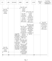
- FIG. 3 a data transmission flowchart of an embodiment of the present application is shown.
- Step 301 the UE sends a TAU request message to the MME entity.
- the UE sends the TAU request message to the MME entity through an evolved Node B (eNB).
- eNB evolved Node B
- Step 302 the MME entity sends a context request message to the AMF entity.
- the MME entity sends the context request message to the AMF entity through the N26 interface.
- Step 303 the AMF entity determines that the UE is in the reachable state in the EPS system.
- Step 304 the AMF entity sends a context request message to the SMF entity and indicates that the UE is in the reachable state in the EPS system.
- the context request message is used to request the session management context information.
- Step 305 the SMF entity determines that the UE is in the reachable state in the EPS system.
- Step 306 the SMF entity returns a downlink data buffering indication and the session management context information of the UE to the AMF entity.
- Step 307 the AMF entity sends the context information of the UE and forwards the downlink data buffering indication returned by the SMF entity to the MME entity.
- Step 308 the MME entity returns a confirmation message to the AMF entity.
- Step 309 the MME entity determines to establish a user plane connection and/or control panel connection of the UE according to the context information of the UE.
- the user plane connection of the UE refers to a connection in which the downlink data is sent to a base station via an SGW and then sent by the base station to the UE via a data radio bearer.
- the MME entity requests to restore the S5 bearer between the SGW and the PGW, and requests the eNB to restore the radio bearer and the S 1 bearer.
- the control plane connection of the UE refers to a connection in which the downlink data is sent to the MME entity via the SGW and then sent by the MME entity to the UE via an NAS message.
- the MME entity establishes the S11 bearer with the SGW.
- Step 310 the MME entity returns a TAU accept message to the UE.
- the MME entity returns the TAU accept message to the UE through the base station (eNB).
- Step 311 the user plane function entity sends the buffered downlink data to the UE through the established user plane connection and/or control plane connection.
- a UE moves from the 5GS system to the EPS system, and the downlink data of the UE is buffered in the SMF entity of the 5GS system.
- FIG. 4 a data transmission flowchart of an embodiment of the present application is shown.
- Step 401 the UE sends a TAU request message to the MME entity.
- the UE sends the TAU request message to the MME entity through a base station (eNB).
- eNB base station
- Step 402 the MME entity sends a context request message to the AMF entity.
- the MME entity sends the context request message to the AMF entity through the N26 interface.
- Step 403 the AMF entity determines that the UE is in the reachable state in the EPS system.
- Step 404 the AMF entity sends a context request message to the SMF entity and indicates that the UE is in the reachable state in the EPS system.
- the context request message is used to request the session management context information.
- Step 405 the SMF entity determines that the UE is in the reachable state in the EPS system.
- Step 406 the SMF entity forwards the buffered downlink data of the UE to the user plane function entity.
- Step 407 the SMF entity returns a downlink data buffering indication and the session management context information of the UE to the AMF entity.
- Step 408 the AMF entity sends the context information of the UE and forwards the downlink data buffering indication returned by the SMF entity to the MME entity.
- Step 409 the MME entity returns a confirmation message to the AMF entity.
- Step 410 the MME entity determines to establish a user plane connection and/or control panel connection of the UE according to the context information of the UE.
- the user plane connection of the UE refers to a connection in which the downlink data is sent to a base station via an SGW and then sent by the base station to the UE via a data radio bearer.
- the MME entity requests to restore the S5 bearer between the SGW and the PGW, and requests the eNB to restore the radio bearer and the S 1 bearer.
- the control plane connection of the UE refers to a connection in which the downlink data is sent to the MME entity via the SGW and then sent by the MME entity to the UE via an NAS message.
- the MME entity establishes the S11 bearer with the SGW.
- Step 411 the MME entity returns a TAU accept message to the UE.
- the MME entity returns the TAU accept message to the UE through the base station (eNB).
- Step 412 the user plane function entity sends the buffered downlink data to the UE through the established user plane connection and/or control plane connection.
- a UE moves from the second mobile communication system to the first mobile communication system.
- the first mobile communication system is an EPS system
- the second mobile communication system is a 5GS system.
- a data transmission system of an embodiment of the present application includes: an SMF entity 50, an AMF entity 51, and an MME entity 52.
- the SMF entity 50 is located in the first mobile communication system
- the AMF entity 51 is located in the first mobile communication system
- the MME entity 52 is located in the second mobile communication system.
- the SMF entity can be used to perform a part of functions of the MME entity in the first mobile communication system, is mainly responsible for establishing and managing sessions for the UE, and can select a suitable user plane function entity for the UE according to the location information of the UE.
- the main functions of the AMF entity include the termination point of the control plane of the wireless access network, the termination point of non-access signaling, the mobility management, the lawful monitoring, the access authorization or authentication, and so on.
- the SMF entity 50 is configured to receive a downlink data buffering indication sent by the MME entity; wherein the downlink data buffering indication is used to indicate that the downlink data of the UE is buffered in the second mobile communication system; and activate a PDU session connection corresponding to the buffered downlink data of the UE, so that the user plane function entity sends the buffered downlink data to the UE through the PDU session connection.
- the AMF entity 51 is configured to receive the downlink data buffering indication sent by the MME entity; and forward the downlink data buffering indication to the SMF entity, so that the SMF entity activates the PDU session connection corresponding to the buffered downlink data of the UE, so that the user plane function entity sends the buffered downlink data to the UE through the PDU session connection.
- the MME entity 52 is configured to determine that the downlink data of the UE is buffered in the SGW of the second mobile communication system; and send the downlink data buffering indication to the SMF entity, so that the SMF entity activates the PDU session connection corresponding to the buffered downlink data of the UE, so that the user plane function entity sends the buffered downlink data to the UE through the PDU session connection.
- the MME entity of the embodiment of the present application sends the downlink data buffering indication to the SMF entity
- the MME entity sends the downlink data buffering indication to the AMF entity
- the AMF entity forwards the downlink data buffering indication to the SMF entity.
- the N26 interface is defined between the AMF entity and the MME entity, so there is a need to forward the downlink data buffering indication through the AMF entity when the SMF entity 50 needs to send the downlink data buffering indication to the MME entity.
- the UE Since the UE moves across systems in the idle state in the embodiment of the present application, the UE is in the unreachable state in the second mobile communication system.
- the downlink data of the UE buffered in the second mobile communication system is buffered in the SGW, and the MME entity requests the SGW to forward the buffered downlink data of the UE to the user plane function entity after the MME entity determines that the UE is in the reachable state in the first mobile communication system.
- the SGW forwards the buffered downlink data of the UE to the user plane function entity through the S5 interface.
- the MME entity determines that the UE is in the reachable state in the first mobile communication system in the following way:
- the MME entity After the MME entity determines that the UE is in the reachable state in the first mobile communication system and determines that the downlink data of the UE is buffered in the SGW of the second mobile communication system, the MME entity sends a downlink data buffering indication to the AMF entity.
- the MME entity sends the EPS bearer identifier corresponding to the buffered downlink data of the UE to the AMF entity.
- the MME entity in this embodiment of the present application sends the downlink data buffering indication and the EPS bearer identifier corresponding to the buffered downlink data to the AMF entity through a single command.
- the MME entity sends the downlink data buffering indication and the EPS bearer identifier corresponding to the buffered downlink data to the AMF entity through different commands; and the order in which the MME entity sends the downlink data buffering indication and the EPS bearer identifier corresponding to the buffered downlink data to the AMF entity is not limited.
- the AMF entity After receiving the EPS bearer identifier corresponding to the buffered downlink data of the UE sent by the MME entity, the AMF entity maps the EPS bearer identifier to a PDU session identifier.
- the AMF entity determines the SMF entity associated with the PDU session according to the PDU session identifier, and sends the PDU session identifier to the determined SMF entity.
- the SMF entity determines the PDU session connection that needs to be activated according to the PDU session identifier sent by the AMF entity.
- the AMF entity forwards the downlink data buffering indication sent by the MME entity to the SMF entity.
- the AMF entity can send the PDU session identifier and the downlink data buffering indication to the SMF entity through a single signaling, or the AMF entity can send the PDU session identifier and the downlink data buffering indication to the SMF entity through different signalings.
- the AMF entity sends a context update request message to the SMF entity, wherein the context update request message carries the downlink data buffering indication and the PDU session identifier.
- the SMF entity After determining the PDU session connection that needs to be activated according to the PDU session identifier sent by the AMF entity, the SMF entity activates the PDU session connection corresponding to the PDU session identifier.
- the user plane function entity After the SMF entity activates the PDU session connection corresponding to the PDU session identifier, the user plane function entity sends the buffered downlink data to the UE through the activated PDU session connection.
- the user plane function entities in the EPS system and the 5GS system are jointly set up.
- the user plane function entity in the EPS system can be called PGW-G
- the user plane function entity in the 5GS system can be called UPF entity. Therefore, when the downlink data of the UE is buffered in the user plane function entity of the second mobile communication system, the user plane function entity can issue the buffered downlink data of the UE to the UE through the PDU session connection of the UE established in the first mobile communication system after the UE moves to the first mobile communication system.
- a UE moves from the EPS system to the 5GS system, and the downlink data of the UE is buffered in the SGW of the EPS system.
- FIG. 6 a data transmission flowchart of an embodiment of the present application is shown.
- Step 601 the UE sends a registration request message to the AMF entity.
- the UE sends the registration request message to the AMF entity through the NG-RAN.
- Step 602 the AMF entity sends a context request message to the MME entity.
- the AMF entity sends the context request message to the MME entity through the N26 interface.
- Step 603 the MME entity determines that the UE is in the reachable state in the 5GS system.
- Step 604 the MME entity requests the SGW to forward the buffered downlink data of the UE to the user plane function entity.
- Step 605 the SGW forwards the buffered downlink data of the UE to the user plane function entity.
- the SGW forwards the buffered downlink data of the UE to the user plane function entity through the S5 interface.
- Step 606 the MME entity sends a downlink data buffering indication to the AMF entity, and the MME entity sends the EPS bearer identifier corresponding to the buffered downlink data to the AMF entity.
- the MME entity sends the downlink data buffering indication and the EPS bearer identifier corresponding to the buffered downlink data to the AMF entity through a response message.
- Step 607 the AMF entity maps the EPS bearer identifier to a PDU session identifier.
- Step 608 the AMF entity sends a context update request message to the SMF entity.
- the context update request message includes the downlink data buffering indication and the PDU session identifier.
- Step 609 the SMF entity activates a corresponding PDU session connection according to the PDU session identifier after receiving the downlink data buffering indication.
- Step 610 the AMF entity returns a registration accept message to the UE.
- Step 611 the user plane function entity sends the buffered downlink data of the UE to the UE through the activated PDU session connection.
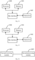
- an embodiment of the present application provides a first MME entity, which is located in a second mobile communication system and includes: a processor 700, a memory 701, a transceiver 702 and a bus interface.
- the processor 700 is responsible for managing the bus architecture and general processing, and the memory 701 may store the data used by the processor 700 when performing the operations.
- the transceiver 702 is configured to receive and send the data under the control of the processor 700.
- the bus architecture may include any numbers of interconnected buses and bridges, and specifically link various circuits of one or more processors represented by the processor 700 and the memory represented by the memory 701.
- the bus architecture may further link various other circuits such as peripheral device, voltage regulator and power management circuit, which are all well known in the art and thus will not be further described again herein.
- the bus interface provides an interface.
- the processor 700 is responsible for managing the bus architecture and general processing, and the memory 701 may store the data used by the processor 700 when performing the operations.
- the procedure disclosed by the embodiment of the present application may be applied in the processor 700 or implemented by the processor 700.
- each step of the signal processing flow may be completed by the integrated logic circuit of hardware in the processor 700 or the instruction in the form of software.
- the processor 700 may be a general-purpose processor, a digital signal processor, an application specific integrated circuit, a field programmable gate array or other programmable logic device, a discrete gate or transistor logic device, or a discrete hardware component, and may implement or perform each method, step and logical block diagram disclosed in the embodiments of the present application.
- the general-purpose processor may be a microprocessor or any conventional processor or the like.
- the steps of the method disclosed in combination with the embodiments of the present application may be directly completed by a hardware processor, or completed by a combination of hardware and software modules in the processor.
- the software modules may be located in the random access memory, flash memory, read only memory, programmable read only memory or electrically erasable programmable read only memory, register and other mature storage medium in the art.
- the storage medium is located in the memory 701, and the processor 700 reads the information in the memory 701 and completes the steps of the signal processing flow in combination with its hardware.
- the processor 700 is configured to read the program in the memory 701 and perform:
- the processor 700 is configured to: receive the downlink data buffering indication sent by the SMF entity through an AMF entity in the first mobile communication system.
- processor 700 is further configured to:
- the first request message is a TAU request message.
- the downlink data of the UE is buffered in a user plane function entity of the first mobile communication system; or, the downlink data of the UE is buffered in the SMF entity of the first mobile communication system.
- the processor 700 is configured to: determine to establish a user plane connection and/or control plane connection according to the context information of the UE.
- the first mobile communication system is a 5GS system
- the second mobile communication system is an EPS system.
- the user plane connection refers to a connection in which the downlink data is sent to a base station via an SGW and then sent by the base station to the UE via a data radio bearer;
- the control plane connection refers to a connection in which the downlink data is sent to the MME entity via the SGW and then sent by the MME entity to the UE via an NAS message.
- an embodiment of the present application provides a first SMF entity, which is located in a first mobile communication system and includes a processor 800, a memory 801, a transceiver 802 and a bus interface.
- the processor 800 is responsible for managing the bus architecture and general processing, and the memory 801 may store the data used by the processor 800 when performing the operations.
- the transceiver 802 is configured to receive and send the data under the control of the processor 800.
- the bus architecture may include any numbers of interconnected buses and bridges, and specifically link various circuits of one or more processors represented by the processor 800 and the memory represented by the memory 801.
- the bus architecture may further link various other circuits such as peripheral device, voltage regulator and power management circuit, which are all well known in the art and thus will not be further described again herein.
- the bus interface provides an interface.
- the processor 800 is responsible for managing the bus architecture and general processing, and the memory 801 may store the data used by the processor 800 when performing the operations.
- the procedure disclosed by the embodiment of the present application may be applied in the processor 800 or implemented by the processor 800.
- each step of the signal processing flow may be completed by the integrated logic circuit of hardware in the processor 800 or the instruction in the form of software.
- the processor 800 may be a general-purpose processor, a digital signal processor, an application specific integrated circuit, a field programmable gate array or other programmable logic device, a discrete gate or transistor logic device, or a discrete hardware component, and may implement or perform each method, step and logical block diagram disclosed in the embodiments of the present application.
- the general-purpose processor may be a microprocessor or any conventional processor or the like.
- the steps of the method disclosed in combination with the embodiments of the present application may be directly completed by a hardware processor, or completed by a combination of hardware and software modules in the processor.
- the software modules may be located in the random access memory, flash memory, read only memory, programmable read only memory or electrically erasable programmable read only memory, register and other mature storage medium in the art.
- the storage medium is located in the memory 801, and the processor 800 reads the information in the memory 801 and completes the steps of the signal processing flow in combination with its hardware.
- the processor 800 is configured to read the program in the memory 801 and perform a process of:
- the processor 800 is configured to: send the downlink data buffering indication to an AMF entity in the first mobile communication system, and send the downlink data buffering indication to the MME entity through the AMF entity.
- the processor 800 is configured to:
- processor 800 is further configured to:
- the processor 800 is further configured to: forward the buffered downlink data of the UE to the user plane function entity after determining that the UE is in the reachable state after moving to the second mobile communication system when the downlink data of the UE is buffered in the SMF entity.
- the first mobile communication system is a 5GS system
- the second mobile communication system is an EPS system.
- the user plane connection refers to a connection in which the downlink data is sent to a base station via an SGW and then sent by the base station to the UE via a data radio bearer;
- the control plane connection refers to a connection in which the downlink data is sent to the MME entity via the SGW and then sent by the MME entity to the UE via an NAS message.
- an embodiment of the present application provides a second MME entity, which is located in a second mobile communication system and includes:
- the first receiving module 901 is configured to: receive the downlink data buffering indication sent by the SMF entity through an AMF entity in the first mobile communication system.
- the first receiving module 901 is further configured to:
- the first request message is a TAU request message.
- the downlink data of the UE is buffered in a user plane function entity of the first mobile communication system; or, the downlink data of the UE is buffered in the SMF entity of the first mobile communication system.
- the first processing module 902 is configured to: determine to establish a user plane connection and/or control plane connection according to the context information of the UE.
- the first mobile communication system is a 5GS system
- the second mobile communication system is an EPS system.
- the user plane connection refers to a connection in which the downlink data is sent to a base station via an SGW and then sent by the base station to the UE via a data radio bearer;
- the control plane connection refers to a connection in which the downlink data is sent to the MME entity via the SGW and then sent by the MME entity to the UE via an NAS message.
- an embodiment of the present application provides a second SMF entity, which is located in a first mobile communication system and includes:
- the first sending module 1002 is configured to: send the downlink data buffering indication to an AMF entity in the first mobile communication system, and send the downlink data buffering indication to the MME entity through the AMF entity.
- the first determining module 1001 is configured to:
- the first sending module 1002 is further configured to:
- the first determining module 1001 is further configured to: forward the buffered downlink data of the UE to the user plane function entity after determining that the UE is in the reachable state after moving to the second mobile communication system when the downlink data of the UE is buffered in the SMF entity.
- the first mobile communication system is a 5GS system
- the second mobile communication system is an EPS system.
- the user plane connection refers to a connection in which the downlink data is sent to a base station via an SGW and then sent by the base station to the UE via a data radio bearer;
- the control plane connection refers to a connection in which the downlink data is sent to the MME entity via the SGW and then sent by the MME entity to the UE via an NAS message.
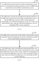
- an embodiment of the present application provides a data transmission method when a UE moves from a first mobile communication system to a second mobile communication system, which includes:
- the step in which the MME entity receives the downlink data buffering indication sent by the SMF entity located in the first mobile communication system includes: the MME entity receives the downlink data buffering indication sent by the SMF entity through an AMF entity in the first mobile communication system.
- the method before the MME entity receives the downlink data buffering indication sent by the SMF entity located in the first mobile communication system, the method further includes:
- the first request message is a TAU request message.
- the downlink data of the UE is buffered in a user plane function entity of the first mobile communication system; or, the downlink data of the UE is buffered in the SMF entity of the first mobile communication system.
- the step in which the MME entity initiates the establishment of the user plane connection and/or control plane connection of the UE includes: the MME entity determines to establish a user plane connection and/or control plane connection according to the context information of the UE.
- the first mobile communication system is a 5GS system
- the second mobile communication system is an EPS system.
- the user plane connection refers to a connection in which the downlink data is sent to a base station via an SGW and then sent by the base station to the UE via a data radio bearer;
- the control plane connection refers to a connection in which the downlink data is sent to the MME entity via the SGW and then sent by the MME entity to the UE via an NAS message.
- an embodiment of the present application provides another data transmission method when a UE moves from a first mobile communication system to a second mobile communication system, which includes:
- the step in which the SMF entity sends the downlink data buffering indication to the MME entity located in the second mobile communication system includes: the SMF entity sends the downlink data buffering indication to an AMF entity in the first mobile communication system, and sends the downlink data buffering indication to the MME entity through the AMF entity.
- the step in which the SMF entity determines that the downlink data of the UE is buffered in the first mobile communication system includes:
- the method further includes:
- the method further includes: the SMF entity forwards the buffered downlink data of the UE to the user plane function entity.
- the first mobile communication system is a 5GS system
- the second mobile communication system is an EPS system.
- the user plane connection refers to a connection in which the downlink data is sent to a base station via an SGW and then sent by the base station to the UE via a data radio bearer;
- the control plane connection refers to a connection in which the downlink data is sent to the MME entity via the SGW and then sent by the MME entity to the UE via an NAS message.
- An embodiment of the present application provides a computer storable medium on which a computer program is stored, where the program, when executed by a processor, implements the steps of the above data transmission method after the UE moves from the first mobile communication system to the second mobile communication system.
- an embodiment of the present application provides a third SMF entity, which is located in a first mobile communication system and includes a processor 1300, a memory 1301, a transceiver 1302 and a bus interface.
- the processor 1300 is responsible for managing the bus architecture and general processing, and the memory 1301 may store the data used by the processor 1300 when performing the operations.
- the transceiver 1302 is configured to receive and send the data under the control of the processor 1300.
- the bus architecture may include any numbers of interconnected buses and bridges, and specifically link various circuits of one or more processors represented by the processor 1300 and the memory represented by the memory 1301.
- the bus architecture may further link various other circuits such as peripheral device, voltage regulator and power management circuit, which are all well known in the art and thus will not be further described again herein.
- the bus interface provides an interface.
- the processor 1300 is responsible for managing the bus architecture and general processing, and the memory 1301 may store the data used by the processor 1300 when performing the operations.
- the procedure disclosed by the embodiment of the present application may be applied in the processor 1300 or implemented by the processor 1300.
- each step of the signal processing flow may be completed by the integrated logic circuit of hardware in the processor 1300 or the instruction in the form of software.
- the processor 1300 may be a general-purpose processor, a digital signal processor, an application specific integrated circuit, a field programmable gate array or other programmable logic device, a discrete gate or transistor logic device, or a discrete hardware component, and may implement or perform each method, step and logical block diagram disclosed in the embodiments of the present application.
- the general-purpose processor may be a microprocessor or any conventional processor or the like.
- the steps of the method disclosed in combination with the embodiments of the present application may be directly completed by a hardware processor, or completed by a combination of hardware and software modules in the processor.
- the software modules may be located in the random access memory, flash memory, read only memory, programmable read only memory or electrically erasable programmable read only memory, register and other mature storage medium in the art.
- the storage medium is located in the memory 1301, and the processor 1300 reads the information in the memory 1301 and completes the steps of the signal processing flow in combination with its hardware.
- the processor 1300 is configured to read the program in the memory 1301 and perform a process of:
- the processor 1300 is configured to: receive the downlink data buffering indication sent by the MME entity through an AMF entity in the first mobile communication system.
- the processor 1300 is configured to: determine a PDU session connection that needs to be activated according to a PDU session identifier sent by the AMF entity; wherein the PDU session identifier is determined by the AMF entity according to an EPS bearer identifier corresponding to the buffered downlink data of the UE that is received.
- the first mobile communication system is a 5GS system
- the second mobile communication system is an EPS system.
- an embodiment of the present application provides a first AMF entity, which is located in a first mobile communication system and includes a processor 1400, a memory 1401, a transceiver 1402 and a bus interface.
- the processor 1400 is responsible for managing the bus architecture and general processing, and the memory 1401 may store the data used by the processor 1400 when performing the operations.
- the transceiver 1402 is configured to receive and send the data under the control of the processor 1400.
- the bus architecture may include any numbers of interconnected buses and bridges, and specifically link various circuits of one or more processors represented by the processor 1400 and the memory represented by the memory 1401.
- the bus architecture may further link various other circuits such as peripheral device, voltage regulator and power management circuit, which are all well known in the art and thus will not be further described again herein.
- the bus interface provides an interface.
- the processor 1400 is responsible for managing the bus architecture and general processing, and the memory 1401 may store the data used by the processor 1400 when performing the operations.
- the procedure disclosed by the embodiment of the present application may be applied in the processor 1400 or implemented by the processor 1400.
- each step of the signal processing flow may be completed by the integrated logic circuit of hardware in the processor 1400 or the instruction in the form of software.
- the processor 1400 may be a general-purpose processor, a digital signal processor, an application specific integrated circuit, a field programmable gate array or other programmable logic device, a discrete gate or transistor logic device, or a discrete hardware component, and may implement or perform each method, step and logical block diagram disclosed in the embodiments of the present application.
- the general-purpose processor may be a microprocessor or any conventional processor or the like.
- the steps of the method disclosed in combination with the embodiments of the present application may be directly completed by a hardware processor, or completed by a combination of hardware and software modules in the processor.
- the software modules may be located in the random access memory, flash memory, read only memory, programmable read only memory or electrically erasable programmable read only memory, register and other mature storage medium in the art.
- the storage medium is located in the memory 1401, and the processor 1400 reads the information in the memory 1401 and completes the steps of the signal processing flow in combination with its hardware.
- the processor 1400 is configured to read the program in the memory 1401 and perform a process of:
- processor 1400 is further configured to:
- the processor 1400 is further configured to: receive an EPS bearer identifier corresponding to the buffered downlink data of the UE sent by the MME entity; map the EPS bearer identifier to a PDU session identifier; and send the PDU session identifier to the SMF entity, so that the SMF entity determines a PDU session connection that needs to be activated according to the PDU session identifier.
- the first mobile communication system is a 5GS system
- the second mobile communication system is an EPS system.
- an embodiment of the present application provides a third MME entity, which is located in a second mobile communication system and includes a processor 1500, a memory 1501, a transceiver 1502 and a bus interface.
- the processor 1500 is responsible for managing the bus architecture and general processing, and the memory 1501 may store the data used by the processor 1500 when performing the operations.
- the transceiver 1502 is configured to receive and send the data under the control of the processor 1500.
- the bus architecture may include any numbers of interconnected buses and bridges, and specifically link various circuits of one or more processors represented by the processor 1500 and the memory represented by the memory 1501.
- the bus architecture may further link various other circuits such as peripheral device, voltage regulator and power management circuit, which are all well known in the art and thus will not be further described again herein.
- the bus interface provides an interface.
- the processor 1500 is responsible for managing the bus architecture and general processing, and the memory 1501 may store the data used by the processor 1500 when performing the operations.
- the procedure disclosed by the embodiment of the present application may be applied in the processor 1500 or implemented by the processor 1500.
- each step of the signal processing flow may be completed by the integrated logic circuit of hardware in the processor 1500 or the instruction in the form of software.
- the processor 1500 may be a general-purpose processor, a digital signal processor, an application specific integrated circuit, a field programmable gate array or other programmable logic device, a discrete gate or transistor logic device, or a discrete hardware component, and may implement or perform each method, step and logical block diagram disclosed in the embodiments of the present application.
- the general-purpose processor may be a microprocessor or any conventional processor or the like.
- the steps of the method disclosed in combination with the embodiments of the present application may be directly completed by a hardware processor, or completed by a combination of hardware and software modules in the processor.
- the software modules may be located in the random access memory, flash memory, read only memory, programmable read only memory or electrically erasable programmable read only memory, register and other mature storage medium in the art.
- the storage medium is located in the memory 1501, and the processor 1500 reads the information in the memory 1501 and completes the steps of the signal processing flow in combination with its hardware.
- the processor 1500 is configured to read the program in the memory 1501 and perform a process of:
- the processor 1500 is configured to: send the downlink data buffering indication to an AMF entity in the first mobile communication system, and send the downlink data buffering indication to the SMF entity through the AMF entity.
- the processor 1500 is further configured to: before sending the downlink data buffering indication to the SMF entity located in the first mobile communication system, receive a fifth request message sent by the AMF entity for requesting the context information of the UE; and determine that the UE is in a reachable state after moving to the first mobile communication system.
- the processor 1500 is further configured to: request the SGW to forward the buffered downlink data of the UE to the user plane function entity after determining that the UE is in the reachable state after moving to the first mobile communication system.
- the processor 1500 is further configured to: send an EPS bearer identifier corresponding to the buffered downlink data of the UE to the AMF entity, so that the AMF entity determines a PDU session identifier according to the EPS bearer identifier.
- the first mobile communication system is a 5GS system
- the second mobile communication system is an EPS system.
- an embodiment of the present application provides a fourth SMF entity, which is located in a first mobile communication system and includes:
- the second receiving module 1601 is configured to: receive the downlink data buffering indication sent by the MME entity through an AMF entity in the first mobile communication system.
- the second processing module 1602 is configured to: determine a PDU session connection that needs to be activated according to a PDU session identifier sent by the AMF entity; wherein the PDU session identifier is determined by the AMF entity according to an EPS bearer identifier corresponding to the buffered downlink data of the UE that is received.
- the first mobile communication system is a 5GS system
- the second mobile communication system is an EPS system.
- an embodiment of the present application provides a second AMF entity, which is located in a first mobile communication system and includes:
- the third receiving module 1701 is further configured to:
- the third receiving module 1701 is further configured to: receive an EPS bearer identifier corresponding to the buffered downlink data of the UE sent by the MME entity; map the EPS bearer identifier to a PDU session identifier; and send the PDU session identifier to the SMF entity, so that the SMF entity determines a PDU session connection that needs to be activated according to the PDU session identifier.
- the first mobile communication system is a 5GS system
- the second mobile communication system is an EPS system.
- an embodiment of the present application provides a fourth MME entity, which is located in a second mobile communication system and includes:
- the third sending module 1802 is configured to: send the downlink data buffering indication to an AMF entity in the first mobile communication system, and send the downlink data buffering indication to the SMF entity through the AMF entity.
- the third sending module 1802 is further configured to: before sending the downlink data buffering indication to the SMF entity located in the first mobile communication system, receive a fifth request message sent by the AMF entity for requesting the context information of the UE; and determine that the UE is in a reachable state after moving to the first mobile communication system.
- the third sending module 1802 is further configured to: request the SGW to forward the buffered downlink data of the UE to the user plane function entity after determining that the UE is in the reachable state after moving to the first mobile communication system.
- the third sending module 1802 is further configured to: send an EPS bearer identifier corresponding to the buffered downlink data of the UE to the AMF entity, so that the AMF entity determines a PDU session identifier according to the EPS bearer identifier.
- the first mobile communication system is a 5GS system
- the second mobile communication system is an EPS system.
- an embodiment of the present application provides a data transmission method when a UE moves from a second mobile communication system to a first mobile communication system, which includes:
- the step in which the SMF entity receives the downlink data buffering indication sent by the MME entity located in the second mobile communication system includes: the SMF entity receives the downlink data buffering indication sent by the MME entity through an AMF entity in the first mobile communication system.
- the step in which the SMF entity activates the PDU session connection corresponding to the buffered downlink data of the UE includes: the SMF entity determines a PDU session connection that needs to be activated according to a PDU session identifier sent by the AMF entity; wherein the PDU session identifier is determined by the AMF entity according to an EPS bearer identifier corresponding to the buffered downlink data of the UE that is received.
- the first mobile communication system is a 5GS system
- the second mobile communication system is an EPS system.
- an embodiment of the present application provides another data transmission method when a UE moves from a second mobile communication system to a first mobile communication system, which includes:
- the method before the AMF entity receives the downlink data buffering indication sent by the MME entity located in the second mobile communication system, the method further includes:
- the method further includes:
- the first mobile communication system is a 5GS system
- the second mobile communication system is an EPS system.
- an embodiment of the present application provides another data transmission method when a UE moves from a second mobile communication system to a first mobile communication system, which includes:
- the step in which the MME entity sends the downlink data buffering indication to the SMF entity located in the first mobile communication system includes: the MME entity sends the downlink data buffering indication to an AMF entity in the first mobile communication system, and sends the downlink data buffering indication to the SMF entity through the AMF entity.
- the method further includes:
- the method further includes: the MME entity requests the SGW to forward the buffered downlink data of the UE to the user plane function entity.
- the method further includes: the MME entity sends an EPS bearer identifier corresponding to the buffered downlink data of the UE to the AMF entity, so that the AMF entity determines a PDU session identifier according to the EPS bearer identifier.
- the first mobile communication system is a 5GS system
- the second mobile communication system is an EPS system.
- An embodiment of the present application provides a computer storable medium on which a computer program is stored, where the program, when executed by a processor, implements the steps of the above data transmission method after the UE moves from the second mobile communication system to the first mobile communication system.
- the computer storage medium may be any available media or data storage device accessible to the computer, including but not limited to magnetic memory (e.g., floppy disk, hard disk, magnetic tape, Magnetic Optical disc (MO) or the like), optical memory (e.g., CD, DVD, BD, HVD or the like), semiconductor memory (e.g., ROM, EPROM, EEPROM, nonvolatile memory (NAND FLASH), Solid State Disk (SSD)) or the like.
- magnetic memory e.g., floppy disk, hard disk, magnetic tape, Magnetic Optical disc (MO) or the like
- optical memory e.g., CD, DVD, BD, HVD or the like
- semiconductor memory e.g., ROM, EPROM, EEPROM, nonvolatile memory (NAND FLASH), Solid State Disk (SSD)
- the present application can also be implemented by the hardware and/or software (including the firmware, resident software, microcode and the like). Further, the present application can adopt the form of computer program products on the computer usable or computer readable storage medium, which has the computer usable or computer readable program codes implemented in the medium, to be used by the instruction execution system or used in combination with the instruction execution system.
- the computer usable or computer readable storage medium can be any medium, which can contain, store, communicate with, transmit or transfer the programs, to be used by the instruction execution system, apparatus or device, or used in combination with the instruction execution system, apparatus or device.
Landscapes
- Engineering & Computer Science (AREA)
- Computer Networks & Wireless Communication (AREA)
- Signal Processing (AREA)
- Computer Security & Cryptography (AREA)
- Databases & Information Systems (AREA)
- Mobile Radio Communication Systems (AREA)
Abstract
Description
- This application is a divisional application of
EP Patent Application NO. 19896235.9 EP Patent Application NO. 19896235.9 PCT/CN2019/119251, filed on November 18, 2019 Chinese Patent Application No. 201811535571.X, filed with the Chinese Patent Office on December 14, 2018 - The present application relates to the field of wireless communication technologies and particularly to a data transmission method and device.
- Since the power saving is an important design goal of a User Equipment (UE), the 3rd Generation Partnership Project (3GPP) defines two kinds of UE power saving modes: Power Saving Mode (PSM) and extended Discontinuous Reception (eDRX).
- When the UE is in the power saving mode, the Access Stratum (AS) receiver will be turned off, the network cannot page the UE, and the UE is in the unreachable state. When the downlink data of the UE arrives at the network, the core network will buffer the downlink data of the UE. When the UE initiates the registration process or service request process again, the UE will restore the reachable state, and the core network sends the buffered data to the UE. However, the UE may switch across communication systems as the UE moves, for example, the UE with 4th-Generation (4G) and 5th-Generation (5G) access capabilities may move between the 4G communication system and the 5G communication system. Therefore, after the UE moves across communication system, if the UE's downlink data is buffered in the source communication system, how to send the buffered downlink data to the UE after the UE moves to the target communication system becomes an urgent problem to be solved.
- To sum up, there is still no solution at present for sending the downlink data buffered in the source communication system to the UE after the UE moves across communication system.
- The present application provides a data transmission method and device, so as to solve the problem that there is no solution for sending the downlink data buffered in the source communication system to the UE after the UE moves across communication system.
- Based on the foregoing problem, in the first aspect, an embodiment of the present application provides a data transmission method, including:
- receiving, by a Mobility Management Entity (MME) located in a second mobile communication system, a downlink data buffering indication sent by a Session Management Function (SMF) entity located in a first mobile communication system; wherein the downlink data buffering indication is used to indicate that downlink data of a UE is buffered in the first mobile communication system;
- initiating, by the MME entity, the establishment of a user plane connection and/or control plane connection of the UE, so that a user plane function entity sends the buffered downlink data to the UE through the user plane connection and/or control plane connection.
- In a second aspect, an embodiment of the present application provides a data transmission method, including:
- determining, by an SMF entity located in a first mobile communication system, that downlink data of a UE is buffered in the first mobile communication system;
- sending, by the SMF entity, a downlink data buffering indication to an MME entity located in a second mobile communication system, so that the MME entity initiates the establishment of a user plane connection and/or control plane connection of the UE after receiving the downlink data buffering indication, so that a user plane function entity sends the buffered downlink data to the UE through the user plane connection and/or control plane connection.
- In a third aspect, an embodiment of the present application provides another data transmission method, including:
- receiving, by an SMF entity located in a first mobile communication system, a downlink data buffering indication sent by an MME entity located in a second mobile communication system; wherein the downlink data buffering indication is used to indicate that downlink data of a UE is buffered in the second mobile communication system;
- activating, by the SMF entity, a Protocol Data Unit (PDU) session connection corresponding to the buffered downlink data of the UE, so that a user plane function entity sends the buffered downlink data to the UE through the PDU session connection.
- In a fourth aspect, an embodiment of the present application provides another data transmission method, including:
- receiving, by an Access and Mobility Management Function (AMF) entity located in a first mobile communication system, a downlink data buffering indication sent by an MME entity located in a second mobile communication system;
- forwarding, by the AMF entity, the downlink data buffering indication to an SMF entity located in the first mobile communication system, so that the SMF entity activates a PDU session connection corresponding to buffered downlink data of a UE, so that a user plane function entity sends the buffered downlink data to the UE through the PDU session connection.
- In a fifth aspect, an embodiment of the present application provides another data transmission method, including:
- determining, by an MME entity located in a second mobile communication system, that downlink data of a UE is buffered in a Serving GateWay (SGW) of the second mobile communication system;
- sending, by the MME entity, a downlink data buffering indication to an SMF entity located in a first mobile communication system, so that the SMF entity activates a PDU session connection corresponding to the buffered downlink data of the UE, so that a user plane function entity sends the buffered downlink data to the UE through the PDU session connection.
- In a sixth aspect, an embodiment of the present application provides a first MME entity, being located in a second mobile communication system and including a processor and a memory;
wherein the processor is configured to read a program in the memory and perform a process of: - receiving a downlink data buffering indication sent by an SMF entity located in a first mobile communication system; wherein the downlink data buffering indication is used to indicate that downlink data of a UE is buffered in the first mobile communication system;
- initiating an establishment of a user plane connection and/or control plane connection of the UE, so that a user plane function entity sends the buffered downlink data to the UE through the user plane connection and/or control plane connection.
- In a seventh aspect, an embodiment of the present application provides a first SMF entity, which is located in a first mobile communication system and includes a processor and a memory;
wherein the processor is configured to read a program in the memory and perform a process of: - determining that downlink data of a UE is buffered in the first mobile communication system;
- sending a downlink data buffering indication to an MME entity located in a second mobile communication system, so that the MME entity initiates the establishment of a user plane connection and/or control plane connection of the UE after receiving the downlink data buffering indication, so that a user plane function entity sends the buffered downlink data to the UE through the user plane connection and/or control plane connection.
- In an eighth aspect, an embodiment of the present application provides a second SMF entity being located in a first mobile communication system and including a processor and a memory;
wherein the processor is configured to read a program in the memory and perform a process of: - receiving a downlink data buffering indication sent by an MME entity located in a second mobile communication system; wherein the downlink data buffering indication is used to indicate that downlink data of a UE is buffered in the second mobile communication system;
- activating a PDU session connection corresponding to the buffered downlink data of the UE, so that a user plane function entity sends the buffered downlink data to the UE through the PDU session connection.
- In a ninth aspect, an embodiment of the present application provides an AMF entity, being located in a first mobile communication system and including a processor and a memory;
wherein the processor is configured to read a program in the memory and perform a process of: - receiving a downlink data buffering indication sent by an MME entity located in a second mobile communication system;
- forwarding the downlink data buffering indication to an SMF entity located in the first mobile communication system, so that the SMF entity activates a PDU session connection corresponding to buffered downlink data of a UE, so that a user plane function entity sends the buffered downlink data to the UE through the PDU session connection.
- In a tenth aspect, an embodiment of the present application provides a second MME entity, being located in a second mobile communication system and including a processor and a memory;
wherein the processor is configured to read a program in the memory and perform a process of: - determining that downlink data of a UE is buffered in an SGW of the second mobile communication system;
- sending a downlink data buffering indication to an SMF entity located in a first mobile communication system, so that the SMF entity activates a PDU session connection corresponding to the buffered downlink data of the UE, so that a user plane function entity sends the buffered downlink data to the UE through the PDU session connection.
- In an eleventh aspect, an embodiment of the present application provides a third MME entity, being located in a second mobile communication system and including:
- a first receiving module configured to receive a downlink data buffering indication sent by an SMF entity located in a first mobile communication system; wherein the downlink data buffering indication is used to indicate that downlink data of a UE is buffered in the first mobile communication system;
- a first processing module configured to initiate the establishment of a user plane connection and/or control plane connection of the UE, so that a user plane function entity sends the buffered downlink data to the UE through the user plane connection and/or control plane connection.
- In a twelfth aspect, the embodiments of the present application provide a third SMF entity, being located in the first mobile communication system and including:
- a first determining module configured to determine that downlink data of a UE is buffered in the first mobile communication system;
- a first sending module configured to send a downlink data buffering indication to an MME entity located in a second mobile communication system, so that the MME entity initiates the establishment of a user plane connection and/or control plane connection of the UE after receiving the downlink data buffering indication, so that a user plane function entity sends the buffered downlink data to the UE through the user plane connection and/or control plane connection.
- In a thirteenth aspect, an embodiment of the present application provides a fourth SMF entity, being located in a first mobile communication system and including:
- a second receiving module configured to receive a downlink data buffering indication sent by an MME entity located in a second mobile communication system; wherein the downlink data buffering indication is used to indicate that downlink data of a UE is buffered in the second mobile communication system;
- a second processing module configured to activate a PDU session connection corresponding to the buffered downlink data of the UE, so that a user plane function entity sends the buffered downlink data to the UE through the PDU session connection.
- In a fourteenth aspect, an embodiment of the present application provides another AMF entity, being located in a first mobile communication system and including:
- a third receiving module configured to receive a downlink data buffering indication sent by an MME entity located in a second mobile communication system;
- a second sending module configured to forward the downlink data buffering indication to an SMF entity located in the first mobile communication system, so that the SMF entity activates a PDU session connection corresponding to buffered downlink data of a UE, so that a user plane function entity sends the buffered downlink data to the UE through the PDU session connection.
- In a fifteenth aspect, the embodiments of the present application provide a fourth MME entity, being located in a second mobile communication system and including:
- a second determining module configured to determine that downlink data of a UE is buffered in an SGW of the second mobile communication system;
- a third sending module configured to send a downlink data buffering indication to an SMF entity located in a first mobile communication system, so that the SMF entity activates a PDU session connection corresponding to the buffered downlink data of the UE, so that a user plane function entity sends the buffered downlink data to the UE through the PDU session connection.
- In a sixteenth aspect, an embodiment of the present application provides a computer storable medium storing a computer program thereon, where the program, when executed by a processor, implements the steps of the method described in the above first aspect or implements the steps of the method described in the above second aspect.
- In a seventeenth aspect, an embodiment of the present application provides another computer storable medium storing a computer program thereon, where the program, when executed by a processor, implements the steps of the method described in the above third aspect, or implements the steps of the method described in the above fourth aspect, or implements the steps of the method described in the above fifth aspect.
- In the embodiments of the present application, after the UE moves from the first mobile communication system to the second mobile communication system, the MME entity in the second mobile communication system establishes a user plane and/or control plane connection of the UE after receiving the downlink data buffering indication sent by the SMF entity in the first mobile communication system, and the buffered downlink data of the UE is sent to the UE through the established user plane and/or control plane, thereby providing a way to send the downlink data buffered in the first mobile communication system to the UE through the user plane and/or control plane connection established by the second mobile communication system after the UE moves to the second mobile communication system, avoiding the loss of the buffered downlink data of the UE, improving the system reliability, and further improving the system performance.
- After the UE moves from the second mobile communication system to the first mobile communication system, the SMF entity in the first mobile communication system receives the downlink data buffering indication sent by the MME entity in the second mobile communication system, and then activates the PDU session connection corresponding to the buffered downlink data of the UE and sends the buffered downlink data of the UE to the UE through the activated PDU session connection, thereby providing a way to send the downlink data buffered in the second mobile communication system to the UE through the activated PDU session connection in the first mobile communication system after the UE moves to the first mobile communication system, avoiding the loss of the buffered downlink data of the UE, improving the system reliability, and further improving the system performance.
-
-
Fig. 1 is a schematic diagram of a system architecture of an embodiment of the present application; -
Fig. 2 is a structural schematic diagram of a first data transmission system of an embodiment of the present application; -
Fig. 3 is a first data transmission flowchart of an embodiment of the present application; -
Fig. 4 is a second data transmission flowchart of an embodiment of the present application; -
Fig. 5 is a structural schematic diagram of a second data transmission system of an embodiment of the present application; -
Fig. 6 is a third data transmission flowchart of an embodiment of the present application; -
Fig. 7 is a structural schematic diagram of a first MME entity of an embodiment of the present application; -
Fig. 8 is a structural schematic diagram of a first SMF entity of an embodiment of the present application; -
Fig. 9 is a structural schematic diagram of a second MME entity of an embodiment of the present application; -
Fig. 10 is a structural schematic diagram of a second SMF entity of an embodiment of the present application; -
Fig. 11 is a flowchart of a first data transmission method of an embodiment of the present application; -
Fig. 12 is a flowchart of a second data transmission method of an embodiment of the present application; -
Fig. 13 is a structural schematic diagram of a third SMF entity of an embodiment of the present application; -
Fig. 14 is a structural schematic diagram of a first AMF entity of an embodiment of the present application; -
Fig. 15 is a structural schematic diagram of a third MME entity of an embodiment of the present application; -
Fig. 16 is a structural schematic diagram of a fourth SMF entity of an embodiment of the present application; -
Fig. 17 is a structural schematic diagram of a second AMF entity of an embodiment of the present application; -
Fig. 18 is a structural schematic diagram of a fourth MME entity of an embodiment of the present application; -
Fig. 19 is a flowchart of a third data transmission method of an embodiment of the present application; -
Fig. 20 is a flowchart of a fourth data transmission method of an embodiment of the present application; -
Fig. 21 is a flowchart of a fifth data transmission method of an embodiment of the present application. - In the following, some terms in the embodiments of the present application are explained so as to facilitate the understanding of those skilled in the art.
- (1) In the embodiments of the present application, the nouns "network" and "system" are often used alternately, but those skilled in the art may understand the meaning thereof.
- (2) The term "a plurality of" in the embodiments of the present application refers to two or more, and other quantifiers are similar thereto.
- (3) "and/or" describes the association relationship of the associated objects, and indicates that there may be three relationships, for example, A and/or B may represent: only A, both A and B, and only B. The character "/" generally indicates that the associated objects have a kind of "or" relationship.
- The network architectures and service scenarios described in the embodiments of the present application are intended to illustrate the technical solutions of the embodiments of the present application more clearly, and do not constitute a limitation on the technical solutions provided in the embodiments of the present application. As can be known by those ordinary skilled in the art, with the evolution of network architectures and the emergence of new service scenarios, the technical solutions provided in the embodiments of the present application are also applicable to similar technical problems.
- In order to make the objects, technical solutions and advantages of the present application clearer, the present application will be further illustrated below in details with reference to the accompanying figures. Obviously the described embodiments are merely a part of the embodiments of the present application but not all the embodiments. Based upon the embodiments of the present application, all of other embodiments obtained by those ordinary skilled in the art without creative work pertain to the protection scope of the present application.
- The present application will be described below in detail with reference to the drawings.
- In order to support the mobility of the UE between the Evolved Packet System (EPS)(or called 4G system) and 5G system, the 3GPP defines the interworking architecture between the EPS system and 5G system.
- The network interworking architecture is as shown in
Fig. 1 . In this architecture, the Home Subscriber Server (HSS) in the EPS system and the Unified Data Management (UDM) entity in the 5GS system are jointly set up, and can be expressed as HSS+UDM 101. - Here, the joint setting can be understood as combining two into one, that is, the HSS and UDM are set together to form one structure.
- The Policy and Charging Rules Function (PCRF) in the EPS system and the Policy Control Function (PCF) in the 5GS system are jointly set up, and can be expressed as PCF+
PCRF 102. - The Packet Data Network GateWay-Control Plane (PGW-C) in the EPS system and the Session Management Function (SMF) in the 5GS system are jointly set up, and can be expressed as SMF+PGW-
C 103. - The Packet Data Network GateWay-User Plane (PGW-U) in the EPS system and the User Plane Function (UPF) in the 5GS system are jointly set up, can be expressed as UPF+PGW-
U 104, and are collectively referred to as a user plane function entity in the embodiments of the present application. - The N26 interface is defined between the Mobility Management Entity (MME) 106 in the EPS system and the Access and Mobility Management Function (AMF) 107 in the 5G system, and is used to transfer the context information of the UE between the EPS system and 5G system.
- In the EPS system, the
UE 110 can communicate with the core network via the Evolved Universal Terrestrial Radio Access Network (E-UTRAN) 108. - In the 5GS system, the
UE 110 can communicate with the core network via the Next Generation-Radio Access Network (NG-RAN). - The
UE 110 may refer to an access terminal, a user unit, a user station, a mobile radio station, a mobile station, a remote station, a remote terminal, a mobile device, a user terminal, a terminal, a wireless communication device, a user agent, or a user device. The access terminal may be a cellular phone, a cordless phone, a Session Initiation Protocol (SIP) phone, a Wireless Local Loop (WLL) station, a Personal Digital Assistant (PDA), a handheld device with wireless communication function, a computing device or other processing device connected to a wireless modem, a vehicle-carried device, a wearable device, an Internet of Things (IoT) device, etc. - It should be noted that the foregoing system architecture is only an example of the system architecture applicable to the embodiments of the present application. Compared with the system architecture shown in
Fig. 1 , the system architecture applicable to the embodiments of the present application can also add other entities or reduce some entities. - The embodiments of the present application are applied to a scenario where the 5GS and EPS are interconnected. In this scenario, the UE has both 4G and 5G access capabilities, and the UE can move between the EPS system and the 5G system.
- Optionally, in an embodiment of the present application, the UE moves across systems in the idle state; specifically, the UE is in the idle state in the source mobile communication system, and the source mobile communication system has the buffered downlink data of the UE, and the downlink data of the UE buffered in the source communication system is sent to the UE through the target communication system after the UE moves to the target communication system.
- The application scenarios of the embodiments of the present application are:
- 1. A UE moves from a first mobile communication system to a second mobile communication system, and the downlink data of the UE is buffered in the first mobile communication system;
- 2. A UE moves from the second mobile communication system to the first mobile communication system, and the downlink data of the UE is buffered in the second mobile communication system.
- In an optional embodiment, the first mobile communication system is an EPS system, and the second mobile communication system is a 5GS system.
- It should be noted that, in the EPS system, the downlink data of the UE is buffered in a Serving GateWay (SGW); and in the 5GS system, the downlink data of the UE is buffered in a user plane function entity or an SMF entity.
- Different scenarios will be illustrated below respectively.
- 1. A UE moves from the first mobile communication system to the second mobile communication system.
- Optionally, the first mobile communication system is an EPS system, and the second mobile communication system is a 5GS system.
- As shown in
Fig. 2 , a data transmission system of an embodiment of the present application includes: anMME entity 20, anSMF entity 21, and anAMF entity 22. - Here, the
SMF entity 21 is located in the first mobile communication system, theMME entity 20 is located in the second mobile communication system, and theAMF entity 22 is located in the first mobile communication system. - The SMF entity can be used to perform a part of functions of the MME entity in the first mobile communication system, is mainly responsible for establishing and managing sessions for the UE, and can select a suitable user plane function entity for the UE according to the location information of the UE.
- The main functions of the AMF entity include the termination point of the control plane of the wireless access network, the termination point of non-access signaling, the mobility management, the lawful monitoring, the access authorization or authentication, and so on.
- The
MME entity 20 is configured to receive a downlink data buffering indication sent by the SMF entity; wherein the downlink data buffering indication is used to indicate that the downlink data of the UE is buffered in the first mobile communication system; and initiate the establishment of the user plane connection and/or control plane connection of the UE, so that the user plane function entity sends the buffered downlink data to the UE through the user plane connection and/or control plane connection. - The
SMF entity 21 is configured to determine that the downlink data of the UE is buffered in the first mobile communication system; and send the downlink data buffering indication to the MME entity, so that the MME entity initiates the establishment of the user plane connection and/or control plane connection of the UE after receiving the downlink data buffering indication, so that the user plane function entity sends the buffered downlink data to the UE through the user plane connection and/or control plane connection. - The
AMF entity 22 is configured to receive the downlink data buffering indication sent by the SMF entity, and send the downlink data buffering indication to the MME entity. - It should be noted that the N26 interface is defined between the AMF entity and the MME entity, so there is a need to forward the downlink data buffering indication through the AMF entity when the SMF entity needs to send the downlink data buffering indication to the MME entity.
- Since the UE moves across systems in the idle state in the embodiment of the present application, the UE is in the unreachable state in the first mobile communication system, and the AMF entity records the UE's state as unreachable.
- Here, the downlink data of the UE buffered in the first mobile communication system includes but is not limited to:
the downlink data of the UE buffered in the user plane function entity, and the downlink data of the UE buffered in the SMF entity. - When the SMF entity determines that the downlink data of the UE is buffered in the first mobile communication system, the following methods may be used:
- 1. The SMF entity determines that it buffers the downlink data of the UE;
- 2. The SMF entity determines that the downlink data of the UE is buffered in the user plane function entity.
- Before the SMF entity determines that the downlink data of the UE is buffered in the first mobile communication system and sends the downlink data buffering indication to the MME entity, the SMF entity also needs to determine that the current UE is in the reachable state.
- In an optional mode, the AMF entity notifies the SMF entity that the UE is in the reachable state in the second mobile communication system.
- Optionally, after the UE in the idle state moves from the first mobile communication system to the second mobile communication system, the UE sends a first request message to the MME entity; and optionally, the first request message is a Tracking Area Update (TAU) message.
- After receiving the first request message sent by the UE, the MME entity sends a second request message for requesting the context information of the UE to the AMF entity; and optionally, the second request message is a context request message for requesting the context of the UE.
- In an implementation, the MME entity sends the second request message to the AMF entity through the N26 interface.
- After receiving the second request message, the AMF entity determines that the UE is in the reachable state after moving to the second mobile communication system, and notifies the SMF entity.
- Optionally, the AMF entity notifies the SMF entity that the UE is in the reachable state in the second mobile communication system in the following way:
- the AMF entity sends a third request message to the SMF entity;
- after receiving the third request message, the SMF entity determines that the UE is in the reachable state after moving to the second mobile communication system.
- Here, the third request message is used to request the session management context information of the UE.
- When the downlink data of the UE is buffered in the first mobile communication system, the SMF entity sends the downlink data buffering indication after determining that the UE is in the reachable state.
- It should be noted that when the downlink data of the UE is buffered in the SMF entity, the SMF entity forwards the buffered downlink data of the UE to the user plane function entity after determining that the UE is in the reachable state in the second mobile communication system.
- In an optional mode, after receiving the third request message and determining that the UE is in the reachable state in the second mobile communication system, the SMF entity sends the downlink data buffering indication and the session management context information of the UE to the AMF entity.
- Correspondingly, the AMF entity returns the downlink data buffering indication and the context information of the UE to the MME entity.
- After receiving the downlink data buffering indication, the MME entity determines to establish a user plane connection and/or control plane connection according to the context information of the UE.
- Optionally, the MME entity determines the type of connection establishment according to the context information of the UE.
- The MME entity can determine the established connection type according to the Packet Data NetWorks (PDN) connection type in the context information of the UE; for example, determine to establish a control plane connection when the PDN connection type is Control Plane only.
- Alternatively, the MME entity judges the connection type according to the result of the previous negotiation with the UE, and optionally, the UE and the MME entity negotiate the connection type during the Attach and TAU process.
- It should be noted that the user plane connection in the embodiments of the present application refers to a connection in which the downlink data is sent to a base station via an SGW and then sent by the base station to the UE via a data radio bearer; and the control plane connection refers to a connection in which the downlink data is sent to the MME entity via the SGW and then sent by the MME entity to the UE via an NAS message.
- After establishing the user plane connection and/or control plane connection of the UE, the user plane function entity sends the buffered downlink data to the UE through the established user plane connection and/or control plane connection.
- It should be noted here that, in the network architecture of the embodiments of the present application, the user plane function entities in the EPS system and the 5GS system are jointly set up. The user plane function entity in the EPS system can be called PGW-G, and the user plane function entity in the 5GS system can be called UPF entity. Therefore, when the downlink data of the UE is buffered in the user plane function entity of the first mobile communication system, the user plane function entity can issue the buffered downlink data of the UE to the UE through the user plane connection and/or control plane connection of the UE established in the second mobile communication system after the UE moves to the second mobile communication system.
- The data transmission methods of the embodiments of the present application will be illustrated below in detail through two specific embodiments.
- In the first embodiment, a UE moves from the 5GS system to the EPS system, and the downlink data of the UE is buffered in the user plane function entity of the 5GS system.
- As shown in
Fig. 3 , a data transmission flowchart of an embodiment of the present application is shown. - Step 301: the UE sends a TAU request message to the MME entity.
- Here, the UE sends the TAU request message to the MME entity through an evolved Node B (eNB).
- Step 302: the MME entity sends a context request message to the AMF entity.
- Optionally, the MME entity sends the context request message to the AMF entity through the N26 interface.
- Step 303: the AMF entity determines that the UE is in the reachable state in the EPS system.
- Step 304: the AMF entity sends a context request message to the SMF entity and indicates that the UE is in the reachable state in the EPS system.
- Here, the context request message is used to request the session management context information.
- Step 305: the SMF entity determines that the UE is in the reachable state in the EPS system.
- Step 306: the SMF entity returns a downlink data buffering indication and the session management context information of the UE to the AMF entity.
- Step 307: the AMF entity sends the context information of the UE and forwards the downlink data buffering indication returned by the SMF entity to the MME entity.
- Step 308: the MME entity returns a confirmation message to the AMF entity.
- Step 309: the MME entity determines to establish a user plane connection and/or control panel connection of the UE according to the context information of the UE.
- Here, the user plane connection of the UE refers to a connection in which the downlink data is sent to a base station via an SGW and then sent by the base station to the UE via a data radio bearer.
- Optionally, the MME entity requests to restore the S5 bearer between the SGW and the PGW, and requests the eNB to restore the radio bearer and the S 1 bearer.
- The control plane connection of the UE refers to a connection in which the downlink data is sent to the MME entity via the SGW and then sent by the MME entity to the UE via an NAS message.
- Optionally, the MME entity establishes the S11 bearer with the SGW.
- Step 310: the MME entity returns a TAU accept message to the UE.
- Optionally, the MME entity returns the TAU accept message to the UE through the base station (eNB).
- Step 311: the user plane function entity sends the buffered downlink data to the UE through the established user plane connection and/or control plane connection.
- A UE moves from the 5GS system to the EPS system, and the downlink data of the UE is buffered in the SMF entity of the 5GS system.
- As shown in
Fig. 4 , a data transmission flowchart of an embodiment of the present application is shown. - Step 401: the UE sends a TAU request message to the MME entity.
- Here, the UE sends the TAU request message to the MME entity through a base station (eNB).
- Step 402: the MME entity sends a context request message to the AMF entity.
- Optionally, the MME entity sends the context request message to the AMF entity through the N26 interface.
- Step 403: the AMF entity determines that the UE is in the reachable state in the EPS system.
- Step 404: the AMF entity sends a context request message to the SMF entity and indicates that the UE is in the reachable state in the EPS system.
- Here, the context request message is used to request the session management context information.
- Step 405: the SMF entity determines that the UE is in the reachable state in the EPS system.
- Step 406: the SMF entity forwards the buffered downlink data of the UE to the user plane function entity.
- Step 407: the SMF entity returns a downlink data buffering indication and the session management context information of the UE to the AMF entity.
- Step 408: the AMF entity sends the context information of the UE and forwards the downlink data buffering indication returned by the SMF entity to the MME entity.
- Step 409: the MME entity returns a confirmation message to the AMF entity.
- Step 410: the MME entity determines to establish a user plane connection and/or control panel connection of the UE according to the context information of the UE.
- Here, the user plane connection of the UE refers to a connection in which the downlink data is sent to a base station via an SGW and then sent by the base station to the UE via a data radio bearer.
- Optionally, the MME entity requests to restore the S5 bearer between the SGW and the PGW, and requests the eNB to restore the radio bearer and the S 1 bearer.
- The control plane connection of the UE refers to a connection in which the downlink data is sent to the MME entity via the SGW and then sent by the MME entity to the UE via an NAS message.
- Optionally, the MME entity establishes the S11 bearer with the SGW.
- Step 411: the MME entity returns a TAU accept message to the UE.
- Optionally, the MME entity returns the TAU accept message to the UE through the base station (eNB).
- Step 412: the user plane function entity sends the buffered downlink data to the UE through the established user plane connection and/or control plane connection.
- 2. A UE moves from the second mobile communication system to the first mobile communication system.
- Optionally, the first mobile communication system is an EPS system, and the second mobile communication system is a 5GS system.
- As shown in
Fig. 5 , a data transmission system of an embodiment of the present application includes: anSMF entity 50, anAMF entity 51, and anMME entity 52. - Here, the
SMF entity 50 is located in the first mobile communication system, theAMF entity 51 is located in the first mobile communication system, and theMME entity 52 is located in the second mobile communication system. - The SMF entity can be used to perform a part of functions of the MME entity in the first mobile communication system, is mainly responsible for establishing and managing sessions for the UE, and can select a suitable user plane function entity for the UE according to the location information of the UE.
- The main functions of the AMF entity include the termination point of the control plane of the wireless access network, the termination point of non-access signaling, the mobility management, the lawful monitoring, the access authorization or authentication, and so on.
- The
SMF entity 50 is configured to receive a downlink data buffering indication sent by the MME entity; wherein the downlink data buffering indication is used to indicate that the downlink data of the UE is buffered in the second mobile communication system; and activate a PDU session connection corresponding to the buffered downlink data of the UE, so that the user plane function entity sends the buffered downlink data to the UE through the PDU session connection. - The
AMF entity 51 is configured to receive the downlink data buffering indication sent by the MME entity; and forward the downlink data buffering indication to the SMF entity, so that the SMF entity activates the PDU session connection corresponding to the buffered downlink data of the UE, so that the user plane function entity sends the buffered downlink data to the UE through the PDU session connection. - The
MME entity 52 is configured to determine that the downlink data of the UE is buffered in the SGW of the second mobile communication system; and send the downlink data buffering indication to the SMF entity, so that the SMF entity activates the PDU session connection corresponding to the buffered downlink data of the UE, so that the user plane function entity sends the buffered downlink data to the UE through the PDU session connection. - Here, when the MME entity of the embodiment of the present application sends the downlink data buffering indication to the SMF entity, the MME entity sends the downlink data buffering indication to the AMF entity, and the AMF entity forwards the downlink data buffering indication to the SMF entity.
- It should be noted that the N26 interface is defined between the AMF entity and the MME entity, so there is a need to forward the downlink data buffering indication through the AMF entity when the
SMF entity 50 needs to send the downlink data buffering indication to the MME entity. - Since the UE moves across systems in the idle state in the embodiment of the present application, the UE is in the unreachable state in the second mobile communication system.
- In an optional mode, the downlink data of the UE buffered in the second mobile communication system is buffered in the SGW, and the MME entity requests the SGW to forward the buffered downlink data of the UE to the user plane function entity after the MME entity determines that the UE is in the reachable state in the first mobile communication system.
- In an implementation, the SGW forwards the buffered downlink data of the UE to the user plane function entity through the S5 interface.
- Optionally, the MME entity determines that the UE is in the reachable state in the first mobile communication system in the following way:
- the AMF entity receives a fourth request message sent by the UE;
- wherein the fourth request message is sent after the UE moves from the second mobile communication system to the first mobile communication system; and optionally, the fourth request message is a registration request message;
- the AMF entity sends a fifth request message for requesting the context information of the UE to the MME entity;
- optionally, the fifth request message is a context request message;
- after receiving the fifth request message, the MME entity determines that the UE is in the reachable state in the first mobile communication system.
- After the MME entity determines that the UE is in the reachable state in the first mobile communication system and determines that the downlink data of the UE is buffered in the SGW of the second mobile communication system, the MME entity sends a downlink data buffering indication to the AMF entity.
- In addition, the MME entity sends the EPS bearer identifier corresponding to the buffered downlink data of the UE to the AMF entity.
- It should be noted here that the MME entity in this embodiment of the present application sends the downlink data buffering indication and the EPS bearer identifier corresponding to the buffered downlink data to the AMF entity through a single command.
- Alternatively, the MME entity sends the downlink data buffering indication and the EPS bearer identifier corresponding to the buffered downlink data to the AMF entity through different commands; and the order in which the MME entity sends the downlink data buffering indication and the EPS bearer identifier corresponding to the buffered downlink data to the AMF entity is not limited.
- After receiving the EPS bearer identifier corresponding to the buffered downlink data of the UE sent by the MME entity, the AMF entity maps the EPS bearer identifier to a PDU session identifier.
- The AMF entity determines the SMF entity associated with the PDU session according to the PDU session identifier, and sends the PDU session identifier to the determined SMF entity.
- Correspondingly, the SMF entity determines the PDU session connection that needs to be activated according to the PDU session identifier sent by the AMF entity.
- In addition, the AMF entity forwards the downlink data buffering indication sent by the MME entity to the SMF entity.
- It should be noted here that the AMF entity can send the PDU session identifier and the downlink data buffering indication to the SMF entity through a single signaling, or the AMF entity can send the PDU session identifier and the downlink data buffering indication to the SMF entity through different signalings.
- In an optional mode, the AMF entity sends a context update request message to the SMF entity, wherein the context update request message carries the downlink data buffering indication and the PDU session identifier.
- After determining the PDU session connection that needs to be activated according to the PDU session identifier sent by the AMF entity, the SMF entity activates the PDU session connection corresponding to the PDU session identifier.
- After the SMF entity activates the PDU session connection corresponding to the PDU session identifier, the user plane function entity sends the buffered downlink data to the UE through the activated PDU session connection.
- It should be noted here that, in the network architecture of the embodiments of the present application, the user plane function entities in the EPS system and the 5GS system are jointly set up. The user plane function entity in the EPS system can be called PGW-G, and the user plane function entity in the 5GS system can be called UPF entity. Therefore, when the downlink data of the UE is buffered in the user plane function entity of the second mobile communication system, the user plane function entity can issue the buffered downlink data of the UE to the UE through the PDU session connection of the UE established in the first mobile communication system after the UE moves to the first mobile communication system.
- The data transmission method of the embodiment of the present application will be illustrated below in detail through a specific embodiment.
- In the third embodiment, a UE moves from the EPS system to the 5GS system, and the downlink data of the UE is buffered in the SGW of the EPS system.
- As shown in
Fig. 6 , a data transmission flowchart of an embodiment of the present application is shown. - Step 601: the UE sends a registration request message to the AMF entity.
- Here, the UE sends the registration request message to the AMF entity through the NG-RAN.
- Step 602: the AMF entity sends a context request message to the MME entity.
- Optionally, the AMF entity sends the context request message to the MME entity through the N26 interface.
- Step 603: the MME entity determines that the UE is in the reachable state in the 5GS system.
- Step 604: the MME entity requests the SGW to forward the buffered downlink data of the UE to the user plane function entity.
- Step 605: the SGW forwards the buffered downlink data of the UE to the user plane function entity.
- Optionally, the SGW forwards the buffered downlink data of the UE to the user plane function entity through the S5 interface.
- Step 606: the MME entity sends a downlink data buffering indication to the AMF entity, and the MME entity sends the EPS bearer identifier corresponding to the buffered downlink data to the AMF entity.
- Optionally, the MME entity sends the downlink data buffering indication and the EPS bearer identifier corresponding to the buffered downlink data to the AMF entity through a response message.
- Step 607: the AMF entity maps the EPS bearer identifier to a PDU session identifier.
- Step 608: the AMF entity sends a context update request message to the SMF entity.
- Here, the context update request message includes the downlink data buffering indication and the PDU session identifier.
- Step 609: the SMF entity activates a corresponding PDU session connection according to the PDU session identifier after receiving the downlink data buffering indication.
- Step 610: the AMF entity returns a registration accept message to the UE.
- Step 611: the user plane function entity sends the buffered downlink data of the UE to the UE through the activated PDU session connection.
- As shown in
Fig. 7 , an embodiment of the present application provides a first MME entity, which is located in a second mobile communication system and includes: aprocessor 700, amemory 701, atransceiver 702 and a bus interface. - The
processor 700 is responsible for managing the bus architecture and general processing, and thememory 701 may store the data used by theprocessor 700 when performing the operations. Thetransceiver 702 is configured to receive and send the data under the control of theprocessor 700. - The bus architecture may include any numbers of interconnected buses and bridges, and specifically link various circuits of one or more processors represented by the
processor 700 and the memory represented by thememory 701. The bus architecture may further link various other circuits such as peripheral device, voltage regulator and power management circuit, which are all well known in the art and thus will not be further described again herein. The bus interface provides an interface. Theprocessor 700 is responsible for managing the bus architecture and general processing, and thememory 701 may store the data used by theprocessor 700 when performing the operations. - The procedure disclosed by the embodiment of the present application may be applied in the
processor 700 or implemented by theprocessor 700. In the implementation process, each step of the signal processing flow may be completed by the integrated logic circuit of hardware in theprocessor 700 or the instruction in the form of software. Theprocessor 700 may be a general-purpose processor, a digital signal processor, an application specific integrated circuit, a field programmable gate array or other programmable logic device, a discrete gate or transistor logic device, or a discrete hardware component, and may implement or perform each method, step and logical block diagram disclosed in the embodiments of the present application. The general-purpose processor may be a microprocessor or any conventional processor or the like. The steps of the method disclosed in combination with the embodiments of the present application may be directly completed by a hardware processor, or completed by a combination of hardware and software modules in the processor. The software modules may be located in the random access memory, flash memory, read only memory, programmable read only memory or electrically erasable programmable read only memory, register and other mature storage medium in the art. The storage medium is located in thememory 701, and theprocessor 700 reads the information in thememory 701 and completes the steps of the signal processing flow in combination with its hardware. - Optionally, the
processor 700 is configured to read the program in thememory 701 and perform: - receive a downlink data buffering indication sent by an SMF entity located in a first mobile communication system; wherein the downlink data buffering indication is used to indicate that the downlink data of a UE is buffered in the first mobile communication system;
- initiate the establishment of a user plane connection and/or control plane connection of the UE, so that a user plane function entity sends the buffered downlink data to the UE through the user plane connection and/or control plane connection.
- Optionally, the
processor 700 is configured to:
receive the downlink data buffering indication sent by the SMF entity through an AMF entity in the first mobile communication system. - Optionally, the
processor 700 is further configured to: - receive a first request message sent by the UE before receiving the downlink data buffering indication sent by the SMF entity in the first mobile communication system; wherein the first request message is sent after the UE moves from the first mobile communication system to the second mobile communication system;
- send a second request message for requesting the context information of the UE to the AMF entity in the first mobile communication system, so that the AMF entity determines that the UE is in a reachable state after moving to the second mobile communication system and notifies the SMF entity after receiving the second request message, so that the SMF entity sends the downlink data buffering indication after determining that the UE is in the reachable state.
- Optionally, the first request message is a TAU request message.
- Optionally, the downlink data of the UE is buffered in a user plane function entity of the first mobile communication system;
or, the downlink data of the UE is buffered in the SMF entity of the first mobile communication system. - Optionally, the
processor 700 is configured to:
determine to establish a user plane connection and/or control plane connection according to the context information of the UE. - Optionally, the first mobile communication system is a 5GS system, and the second mobile communication system is an EPS system.
- Optionally, the user plane connection refers to a connection in which the downlink data is sent to a base station via an SGW and then sent by the base station to the UE via a data radio bearer;
the control plane connection refers to a connection in which the downlink data is sent to the MME entity via the SGW and then sent by the MME entity to the UE via an NAS message. - As shown in
Fig. 8 , an embodiment of the present application provides a first SMF entity, which is located in a first mobile communication system and includes aprocessor 800, amemory 801, atransceiver 802 and a bus interface. - The
processor 800 is responsible for managing the bus architecture and general processing, and thememory 801 may store the data used by theprocessor 800 when performing the operations. Thetransceiver 802 is configured to receive and send the data under the control of theprocessor 800. - The bus architecture may include any numbers of interconnected buses and bridges, and specifically link various circuits of one or more processors represented by the
processor 800 and the memory represented by thememory 801. The bus architecture may further link various other circuits such as peripheral device, voltage regulator and power management circuit, which are all well known in the art and thus will not be further described again herein. The bus interface provides an interface. Theprocessor 800 is responsible for managing the bus architecture and general processing, and thememory 801 may store the data used by theprocessor 800 when performing the operations. - The procedure disclosed by the embodiment of the present application may be applied in the
processor 800 or implemented by theprocessor 800. In the implementation process, each step of the signal processing flow may be completed by the integrated logic circuit of hardware in theprocessor 800 or the instruction in the form of software. Theprocessor 800 may be a general-purpose processor, a digital signal processor, an application specific integrated circuit, a field programmable gate array or other programmable logic device, a discrete gate or transistor logic device, or a discrete hardware component, and may implement or perform each method, step and logical block diagram disclosed in the embodiments of the present application. The general-purpose processor may be a microprocessor or any conventional processor or the like. The steps of the method disclosed in combination with the embodiments of the present application may be directly completed by a hardware processor, or completed by a combination of hardware and software modules in the processor. The software modules may be located in the random access memory, flash memory, read only memory, programmable read only memory or electrically erasable programmable read only memory, register and other mature storage medium in the art. The storage medium is located in thememory 801, and theprocessor 800 reads the information in thememory 801 and completes the steps of the signal processing flow in combination with its hardware. - Optionally, the
processor 800 is configured to read the program in thememory 801 and perform a process of: - determining that the downlink data of a UE is buffered in the first mobile communication system;
- sending a downlink data buffering indication to an MME entity located in a second mobile communication system, so that the MME entity initiates the establishment of a user plane connection and/or control plane connection of the UE after receiving the downlink data buffering indication, so that a user plane function entity sends the buffered downlink data to the UE through the user plane connection and/or control plane connection.
- Optionally, the
processor 800 is configured to:
send the downlink data buffering indication to an AMF entity in the first mobile communication system, and send the downlink data buffering indication to the MME entity through the AMF entity. - Optionally, the
processor 800 is configured to: - determine that the SMF entity buffers the downlink data of the UE;
- or, determine that the downlink data of the UE is buffered in the user plane function entity.
- Optionally, the
processor 800 is further configured to: - receive a third request message sent by the AMF entity for requesting the session management context information of the UE before sending the downlink data buffering indication to the MME entity located in the second mobile communication system; wherein the third request message is sent after the AMF entity receives a second request message sent by the MME entity for requesting the context information of the UE and determines that the UE is in a reachable state;
- determine that the UE is in the reachable state after moving to the second mobile communication system.
- Optionally, the
processor 800 is further configured to:
forward the buffered downlink data of the UE to the user plane function entity after determining that the UE is in the reachable state after moving to the second mobile communication system when the downlink data of the UE is buffered in the SMF entity. - Optionally, the first mobile communication system is a 5GS system, and the second mobile communication system is an EPS system.
- Optionally, the user plane connection refers to a connection in which the downlink data is sent to a base station via an SGW and then sent by the base station to the UE via a data radio bearer;
the control plane connection refers to a connection in which the downlink data is sent to the MME entity via the SGW and then sent by the MME entity to the UE via an NAS message. - As shown in
Fig. 9 , an embodiment of the present application provides a second MME entity, which is located in a second mobile communication system and includes: - a
first receiving module 901 configured to receive a downlink data buffering indication sent by an SMF entity located in a first mobile communication system; wherein the downlink data buffering indication is used to indicate that the downlink data of a UE is buffered in the first mobile communication system; - a
first processing module 902 configured to initiate the establishment of a user plane connection and/or control plane connection of the UE, so that a user plane function entity sends the buffered downlink data to the UE through the user plane connection and/or control plane connection. - Optionally, the
first receiving module 901 is configured to:
receive the downlink data buffering indication sent by the SMF entity through an AMF entity in the first mobile communication system. - Optionally, the
first receiving module 901 is further configured to: - receive a first request message sent by the UE before receiving the downlink data buffering indication sent by the SMF entity in the first mobile communication system; wherein the first request message is sent after the UE moves from the first mobile communication system to the second mobile communication system;
- send a second request message for requesting the context information of the UE to the AMF entity in the first mobile communication system, so that the AMF entity determines that the UE is in a reachable state after moving to the second mobile communication system and notifies the SMF entity after receiving the second request message, so that the SMF entity sends the downlink data buffering indication after determining that the UE is in the reachable state.
- Optionally, the first request message is a TAU request message.
- Optionally, the downlink data of the UE is buffered in a user plane function entity of the first mobile communication system;
or, the downlink data of the UE is buffered in the SMF entity of the first mobile communication system. - Optionally, the
first processing module 902 is configured to:
determine to establish a user plane connection and/or control plane connection according to the context information of the UE. - Optionally, the first mobile communication system is a 5GS system, and the second mobile communication system is an EPS system.
- Optionally, the user plane connection refers to a connection in which the downlink data is sent to a base station via an SGW and then sent by the base station to the UE via a data radio bearer;
the control plane connection refers to a connection in which the downlink data is sent to the MME entity via the SGW and then sent by the MME entity to the UE via an NAS message. - As shown in
Fig. 10 , an embodiment of the present application provides a second SMF entity, which is located in a first mobile communication system and includes: - a first determining
module 1001 configured to determine that the downlink data of a UE is buffered in the first mobile communication system; - a
first sending module 1002 configured to send a downlink data buffering indication to an MME entity located in a second mobile communication system, so that the MME entity initiates the establishment of a user plane connection and/or control plane connection of the UE after receiving the downlink data buffering indication, so that a user plane function entity sends the buffered downlink data to the UE through the user plane connection and/or control plane connection. - Optionally, the
first sending module 1002 is configured to:
send the downlink data buffering indication to an AMF entity in the first mobile communication system, and send the downlink data buffering indication to the MME entity through the AMF entity. - Optionally, the first determining
module 1001 is configured to: - determine that the SMF entity buffers the downlink data of the UE;
- or, determine that the downlink data of the UE is buffered in the user plane function entity.
- Optionally, the
first sending module 1002 is further configured to: - receive a third request message sent by the AMF entity for requesting the session management context information of the UE before sending the downlink data buffering indication to the MME entity located in the second mobile communication system; wherein the third request message is sent after the AMF entity receives a second request message sent by the MME entity for requesting the context information of the UE and determines that the UE is in a reachable state;
- determine that the UE is in the reachable state after moving to the second mobile communication system.
- Optionally, the first determining
module 1001 is further configured to:
forward the buffered downlink data of the UE to the user plane function entity after determining that the UE is in the reachable state after moving to the second mobile communication system when the downlink data of the UE is buffered in the SMF entity. - Optionally, the first mobile communication system is a 5GS system, and the second mobile communication system is an EPS system.
- Optionally, the user plane connection refers to a connection in which the downlink data is sent to a base station via an SGW and then sent by the base station to the UE via a data radio bearer;
the control plane connection refers to a connection in which the downlink data is sent to the MME entity via the SGW and then sent by the MME entity to the UE via an NAS message. - It should be noted that the above functions performed by the MME entity shown in
Fig. 7 and Fig. 9 and the above functions performed by the SMF entity shown inFig. 8 andFig. 10 are applicable to the scenarios in which the UE moves from the first mobile communication system to the second mobile communication system. - As shown in
Fig. 11 , an embodiment of the present application provides a data transmission method when a UE moves from a first mobile communication system to a second mobile communication system, which includes: - Step 1101: an MME entity located in the second mobile communication system receives a downlink data buffering indication sent by an SMF entity located in the first mobile communication system; wherein the downlink data buffering indication is used to indicate that the downlink data of the UE is buffered in the first mobile communication system;
- Step 1102: the MME entity initiates the establishment of a user plane connection and/or control plane connection of the UE, so that a user plane function entity sends the buffered downlink data to the UE through the user plane connection and/or control plane connection.
- Optionally, the step in which the MME entity receives the downlink data buffering indication sent by the SMF entity located in the first mobile communication system includes:
the MME entity receives the downlink data buffering indication sent by the SMF entity through an AMF entity in the first mobile communication system. - Optionally, before the MME entity receives the downlink data buffering indication sent by the SMF entity located in the first mobile communication system, the method further includes:
- the MME entity receives a first request message sent by the UE; wherein the first request message is sent after the UE moves from the first mobile communication system to the second mobile communication system;
- the MME entity sends a second request message for requesting the context information of the UE to the AMF entity in the first mobile communication system, so that the AMF entity determines that the UE is in a reachable state after moving to the second mobile communication system and notifies the SMF entity after receiving the second request message, so that the SMF entity sends the downlink data buffering indication after determining that the UE is in the reachable state.
- Optionally, the first request message is a TAU request message.
- Optionally, the downlink data of the UE is buffered in a user plane function entity of the first mobile communication system;
or, the downlink data of the UE is buffered in the SMF entity of the first mobile communication system. - Optionally, the step in which the MME entity initiates the establishment of the user plane connection and/or control plane connection of the UE includes:
the MME entity determines to establish a user plane connection and/or control plane connection according to the context information of the UE. - Optionally, the first mobile communication system is a 5GS system, and the second mobile communication system is an EPS system.
- Optionally, the user plane connection refers to a connection in which the downlink data is sent to a base station via an SGW and then sent by the base station to the UE via a data radio bearer;
the control plane connection refers to a connection in which the downlink data is sent to the MME entity via the SGW and then sent by the MME entity to the UE via an NAS message. - As shown in
Fig. 12 , an embodiment of the present application provides another data transmission method when a UE moves from a first mobile communication system to a second mobile communication system, which includes: - Step 1201: an SMF entity located in the first mobile communication system determines that the downlink data of the UE is buffered in the first mobile communication system;
- Step 1202: the SMF entity sends a downlink data buffering indication to an MME entity located in the second mobile communication system, so that the MME entity initiates the establishment of a user plane connection and/or control plane connection of the UE after receiving the downlink data buffering indication, so that a user plane function entity sends the buffered downlink data to the UE through the user plane connection and/or control plane connection.
- Optionally, the step in which the SMF entity sends the downlink data buffering indication to the MME entity located in the second mobile communication system includes:
the SMF entity sends the downlink data buffering indication to an AMF entity in the first mobile communication system, and sends the downlink data buffering indication to the MME entity through the AMF entity. - Optionally, the step in which the SMF entity determines that the downlink data of the UE is buffered in the first mobile communication system includes:
- the SMF entity determines that it buffers the downlink data of the UE;
- or, the SMF entity determines that the downlink data of the UE is buffered in the user plane function entity.
- Optionally, before the SMF entity sends the downlink data buffering indication to the MME entity located in the second mobile communication system, the method further includes:
- the SMF entity receives a third request message sent by the AMF entity for requesting the session management context information of the UE; wherein the third request message is sent after the AMF entity receives a second request message sent by the MME entity for requesting the context information of the UE and determines that the UE is in a reachable state;
- the SMF entity determines that the UE is in the reachable state after moving to the second mobile communication system.
- Optionally, when the downlink data of the UE is buffered in the SMF entity, and after the SMF entity determines that the UE is in the reachable state after moving to the second mobile communication system, the method further includes:
the SMF entity forwards the buffered downlink data of the UE to the user plane function entity. - Optionally, the first mobile communication system is a 5GS system, and the second mobile communication system is an EPS system.
- Optionally, the user plane connection refers to a connection in which the downlink data is sent to a base station via an SGW and then sent by the base station to the UE via a data radio bearer;
the control plane connection refers to a connection in which the downlink data is sent to the MME entity via the SGW and then sent by the MME entity to the UE via an NAS message. - An embodiment of the present application provides a computer storable medium on which a computer program is stored, where the program, when executed by a processor, implements the steps of the above data transmission method after the UE moves from the first mobile communication system to the second mobile communication system.
- As shown in
Fig. 13 , an embodiment of the present application provides a third SMF entity, which is located in a first mobile communication system and includes aprocessor 1300, amemory 1301, atransceiver 1302 and a bus interface. - The
processor 1300 is responsible for managing the bus architecture and general processing, and thememory 1301 may store the data used by theprocessor 1300 when performing the operations. Thetransceiver 1302 is configured to receive and send the data under the control of theprocessor 1300. - The bus architecture may include any numbers of interconnected buses and bridges, and specifically link various circuits of one or more processors represented by the
processor 1300 and the memory represented by thememory 1301. The bus architecture may further link various other circuits such as peripheral device, voltage regulator and power management circuit, which are all well known in the art and thus will not be further described again herein. The bus interface provides an interface. Theprocessor 1300 is responsible for managing the bus architecture and general processing, and thememory 1301 may store the data used by theprocessor 1300 when performing the operations. - The procedure disclosed by the embodiment of the present application may be applied in the
processor 1300 or implemented by theprocessor 1300. In the implementation process, each step of the signal processing flow may be completed by the integrated logic circuit of hardware in theprocessor 1300 or the instruction in the form of software. Theprocessor 1300 may be a general-purpose processor, a digital signal processor, an application specific integrated circuit, a field programmable gate array or other programmable logic device, a discrete gate or transistor logic device, or a discrete hardware component, and may implement or perform each method, step and logical block diagram disclosed in the embodiments of the present application. The general-purpose processor may be a microprocessor or any conventional processor or the like. The steps of the method disclosed in combination with the embodiments of the present application may be directly completed by a hardware processor, or completed by a combination of hardware and software modules in the processor. The software modules may be located in the random access memory, flash memory, read only memory, programmable read only memory or electrically erasable programmable read only memory, register and other mature storage medium in the art. The storage medium is located in thememory 1301, and theprocessor 1300 reads the information in thememory 1301 and completes the steps of the signal processing flow in combination with its hardware. - Optionally, the
processor 1300 is configured to read the program in thememory 1301 and perform a process of: - receiving a downlink data buffering indication sent by an MME entity located in a second mobile communication system; wherein the downlink data buffering indication is used to indicate that the downlink data of a UE is buffered in the second mobile communication system;
- activating a PDU session connection corresponding to the buffered downlink data of the UE, so that a user plane function entity sends the buffered downlink data to the UE through the PDU session connection.
- Optionally, the
processor 1300 is configured to:
receive the downlink data buffering indication sent by the MME entity through an AMF entity in the first mobile communication system. - Optionally, the
processor 1300 is configured to:
determine a PDU session connection that needs to be activated according to a PDU session identifier sent by the AMF entity; wherein the PDU session identifier is determined by the AMF entity according to an EPS bearer identifier corresponding to the buffered downlink data of the UE that is received. - Optionally, the first mobile communication system is a 5GS system, and the second mobile communication system is an EPS system.
- As shown in
Fig. 14 , an embodiment of the present application provides a first AMF entity, which is located in a first mobile communication system and includes aprocessor 1400, amemory 1401, atransceiver 1402 and a bus interface. - The
processor 1400 is responsible for managing the bus architecture and general processing, and thememory 1401 may store the data used by theprocessor 1400 when performing the operations. Thetransceiver 1402 is configured to receive and send the data under the control of theprocessor 1400. - The bus architecture may include any numbers of interconnected buses and bridges, and specifically link various circuits of one or more processors represented by the
processor 1400 and the memory represented by thememory 1401. The bus architecture may further link various other circuits such as peripheral device, voltage regulator and power management circuit, which are all well known in the art and thus will not be further described again herein. The bus interface provides an interface. Theprocessor 1400 is responsible for managing the bus architecture and general processing, and thememory 1401 may store the data used by theprocessor 1400 when performing the operations. - The procedure disclosed by the embodiment of the present application may be applied in the
processor 1400 or implemented by theprocessor 1400. In the implementation process, each step of the signal processing flow may be completed by the integrated logic circuit of hardware in theprocessor 1400 or the instruction in the form of software. Theprocessor 1400 may be a general-purpose processor, a digital signal processor, an application specific integrated circuit, a field programmable gate array or other programmable logic device, a discrete gate or transistor logic device, or a discrete hardware component, and may implement or perform each method, step and logical block diagram disclosed in the embodiments of the present application. The general-purpose processor may be a microprocessor or any conventional processor or the like. The steps of the method disclosed in combination with the embodiments of the present application may be directly completed by a hardware processor, or completed by a combination of hardware and software modules in the processor. The software modules may be located in the random access memory, flash memory, read only memory, programmable read only memory or electrically erasable programmable read only memory, register and other mature storage medium in the art. The storage medium is located in thememory 1401, and theprocessor 1400 reads the information in thememory 1401 and completes the steps of the signal processing flow in combination with its hardware. - Optionally, the
processor 1400 is configured to read the program in thememory 1401 and perform a process of: - receiving a downlink data buffering indication sent by an MME entity located in a second mobile communication system;
- forwarding the downlink data buffering indication to an SMF entity located in the first mobile communication system, so that the SMF entity activates a PDU session connection corresponding to the buffered downlink data of a UE, so that a user plane function entity sends the buffered downlink data to the UE through the PDU session connection.
- Optionally, the
processor 1400 is further configured to: - receive a fourth request message sent by the UE before receiving the downlink data buffering indication sent by the MME entity located in the second mobile communication system; wherein the fourth request message is sent after the UE moves from the second mobile communication system to the first mobile communication system;
- send a fifth request message for requesting the context information of the UE to the MME entity, so that the MME entity determines that the UE is in a reachable state after moving to the first mobile communication system after receiving the fifth request message and sends the downlink data buffering indication after determining that the UE is in the reachable state.
- Optionally, the
processor 1400 is further configured to:
receive an EPS bearer identifier corresponding to the buffered downlink data of the UE sent by the MME entity; map the EPS bearer identifier to a PDU session identifier; and send the PDU session identifier to the SMF entity, so that the SMF entity determines a PDU session connection that needs to be activated according to the PDU session identifier. - Optionally, the first mobile communication system is a 5GS system, and the second mobile communication system is an EPS system.
- As shown in
Fig. 15 , an embodiment of the present application provides a third MME entity, which is located in a second mobile communication system and includes aprocessor 1500, amemory 1501, atransceiver 1502 and a bus interface. - The
processor 1500 is responsible for managing the bus architecture and general processing, and thememory 1501 may store the data used by theprocessor 1500 when performing the operations. Thetransceiver 1502 is configured to receive and send the data under the control of theprocessor 1500. - The bus architecture may include any numbers of interconnected buses and bridges, and specifically link various circuits of one or more processors represented by the
processor 1500 and the memory represented by thememory 1501. The bus architecture may further link various other circuits such as peripheral device, voltage regulator and power management circuit, which are all well known in the art and thus will not be further described again herein. The bus interface provides an interface. Theprocessor 1500 is responsible for managing the bus architecture and general processing, and thememory 1501 may store the data used by theprocessor 1500 when performing the operations. - The procedure disclosed by the embodiment of the present application may be applied in the
processor 1500 or implemented by theprocessor 1500. In the implementation process, each step of the signal processing flow may be completed by the integrated logic circuit of hardware in theprocessor 1500 or the instruction in the form of software. Theprocessor 1500 may be a general-purpose processor, a digital signal processor, an application specific integrated circuit, a field programmable gate array or other programmable logic device, a discrete gate or transistor logic device, or a discrete hardware component, and may implement or perform each method, step and logical block diagram disclosed in the embodiments of the present application. The general-purpose processor may be a microprocessor or any conventional processor or the like. The steps of the method disclosed in combination with the embodiments of the present application may be directly completed by a hardware processor, or completed by a combination of hardware and software modules in the processor. The software modules may be located in the random access memory, flash memory, read only memory, programmable read only memory or electrically erasable programmable read only memory, register and other mature storage medium in the art. The storage medium is located in thememory 1501, and theprocessor 1500 reads the information in thememory 1501 and completes the steps of the signal processing flow in combination with its hardware. - Optionally, the
processor 1500 is configured to read the program in thememory 1501 and perform a process of: - determining that the downlink data of a UE is buffered in an SGW of the second mobile communication system;
- sending a downlink data buffering indication to an SMF entity located in a first mobile communication system, so that the SMF entity activates a PDU session connection corresponding to the buffered downlink data of the UE, so that a user plane function entity sends the buffered downlink data to the UE through the PDU session connection.
- Optionally, the
processor 1500 is configured to:
send the downlink data buffering indication to an AMF entity in the first mobile communication system, and send the downlink data buffering indication to the SMF entity through the AMF entity. - Optionally, the
processor 1500 is further configured to:
before sending the downlink data buffering indication to the SMF entity located in the first mobile communication system, receive a fifth request message sent by the AMF entity for requesting the context information of the UE; and determine that the UE is in a reachable state after moving to the first mobile communication system. - Optionally, the
processor 1500 is further configured to:
request the SGW to forward the buffered downlink data of the UE to the user plane function entity after determining that the UE is in the reachable state after moving to the first mobile communication system. - Optionally, the
processor 1500 is further configured to:
send an EPS bearer identifier corresponding to the buffered downlink data of the UE to the AMF entity, so that the AMF entity determines a PDU session identifier according to the EPS bearer identifier. - Optionally, the first mobile communication system is a 5GS system, and the second mobile communication system is an EPS system.
- As shown in
Fig. 16 , an embodiment of the present application provides a fourth SMF entity, which is located in a first mobile communication system and includes: - a
second receiving module 1601 configured to receive a downlink data buffering indication sent by an MME entity located in a second mobile communication system; wherein the downlink data buffering indication is used to indicate that the downlink data of a UE is buffered in the second mobile communication system; - a
second processing module 1602 configured to activate a PDU session connection corresponding to the buffered downlink data of the UE, so that a user plane function entity sends the buffered downlink data to the UE through the PDU session connection. - Optionally, the
second receiving module 1601 is configured to:
receive the downlink data buffering indication sent by the MME entity through an AMF entity in the first mobile communication system. - Optionally, the
second processing module 1602 is configured to:
determine a PDU session connection that needs to be activated according to a PDU session identifier sent by the AMF entity; wherein the PDU session identifier is determined by the AMF entity according to an EPS bearer identifier corresponding to the buffered downlink data of the UE that is received. - Optionally, the first mobile communication system is a 5GS system, and the second mobile communication system is an EPS system.
- As shown in
Fig. 17 , an embodiment of the present application provides a second AMF entity, which is located in a first mobile communication system and includes: - a
third receiving module 1701 configured to receive a downlink data buffering indication sent by an MME entity located in a second mobile communication system; - a
second sending module 1702 configured to forward the downlink data buffering indication to an SMF entity located in the first mobile communication system, so that the SMF entity activates a PDU session connection corresponding to the buffered downlink data of a UE, so that a user plane function entity sends the buffered downlink data to the UE through the PDU session connection. - Optionally, the
third receiving module 1701 is further configured to: - receive a fourth request message sent by the UE before receiving the downlink data buffering indication sent by the MME entity located in the second mobile communication system; wherein the fourth request message is sent after the UE moves from the second mobile communication system to the first mobile communication system;
- send a fifth request message for requesting the context information of the UE to the MME entity, so that the MME entity determines that the UE is in a reachable state after moving to the first mobile communication system after receiving the fifth request message and sends the downlink data buffering indication after determining that the UE is in the reachable state.
- Optionally, the
third receiving module 1701 is further configured to:
receive an EPS bearer identifier corresponding to the buffered downlink data of the UE sent by the MME entity; map the EPS bearer identifier to a PDU session identifier; and send the PDU session identifier to the SMF entity, so that the SMF entity determines a PDU session connection that needs to be activated according to the PDU session identifier. - Optionally, the first mobile communication system is a 5GS system, and the second mobile communication system is an EPS system.
- As shown in
Fig. 18 , an embodiment of the present application provides a fourth MME entity, which is located in a second mobile communication system and includes: - a second determining
module 1801 configured to determine that the downlink data of a UE is buffered in an SGW of the second mobile communication system; - a third sending module 1802 configured to send a downlink data buffering indication to an SMF entity located in a first mobile communication system, so that the SMF entity activates a PDU session connection corresponding to the buffered downlink data of the UE, so that a user plane function entity sends the buffered downlink data to the UE through the PDU session connection.
- Optionally, the third sending module 1802 is configured to:
send the downlink data buffering indication to an AMF entity in the first mobile communication system, and send the downlink data buffering indication to the SMF entity through the AMF entity. - Optionally, the third sending module 1802 is further configured to:
before sending the downlink data buffering indication to the SMF entity located in the first mobile communication system, receive a fifth request message sent by the AMF entity for requesting the context information of the UE; and determine that the UE is in a reachable state after moving to the first mobile communication system. - Optionally, the third sending module 1802 is further configured to:
request the SGW to forward the buffered downlink data of the UE to the user plane function entity after determining that the UE is in the reachable state after moving to the first mobile communication system. - Optionally, the third sending module 1802 is further configured to:
send an EPS bearer identifier corresponding to the buffered downlink data of the UE to the AMF entity, so that the AMF entity determines a PDU session identifier according to the EPS bearer identifier. - Optionally, the first mobile communication system is a 5GS system, and the second mobile communication system is an EPS system.
- It should be noted that the above functions performed by the SMF entity shown in
Fig. 13 andFig. 16 , the above functions performed by the AMF entity shown inFig. 14 andFig. 17 , and the above functions performed by the MME entity shown inFig. 15 andFig. 18 are applicable to the scenarios in which the UE moves from the second mobile communication system to the first mobile communication system. - As shown in
Fig. 19 , an embodiment of the present application provides a data transmission method when a UE moves from a second mobile communication system to a first mobile communication system, which includes: - Step 1901: an SMF entity located in the first mobile communication system receives a downlink data buffering indication sent by an MME entity located in the second mobile communication system; wherein the downlink data buffering indication is used to indicate that the downlink data of the UE is buffered in the second mobile communication system;
- Step 1902: the SMF entity activates a PDU session connection corresponding to the buffered downlink data of the UE, so that a user plane function entity sends the buffered downlink data to the UE through the PDU session connection.
- Optionally, the step in which the SMF entity receives the downlink data buffering indication sent by the MME entity located in the second mobile communication system includes:
the SMF entity receives the downlink data buffering indication sent by the MME entity through an AMF entity in the first mobile communication system. - Optionally, the step in which the SMF entity activates the PDU session connection corresponding to the buffered downlink data of the UE includes:
the SMF entity determines a PDU session connection that needs to be activated according to a PDU session identifier sent by the AMF entity; wherein the PDU session identifier is determined by the AMF entity according to an EPS bearer identifier corresponding to the buffered downlink data of the UE that is received. - Optionally, the first mobile communication system is a 5GS system, and the second mobile communication system is an EPS system.
- As shown in
Fig. 20 , an embodiment of the present application provides another data transmission method when a UE moves from a second mobile communication system to a first mobile communication system, which includes: - Step 2001: an AMF entity located in the first mobile communication system receives a downlink data buffering indication sent by an MME entity located in the second mobile communication system;
- Step 2002: the AMF entity forwards the downlink data buffering indication to an SMF entity located in the first mobile communication system, so that the SMF entity activates a PDU session connection corresponding to the buffered downlink data of the UE, so that a user plane function entity sends the buffered downlink data to the UE through the PDU session connection.
- Optionally, before the AMF entity receives the downlink data buffering indication sent by the MME entity located in the second mobile communication system, the method further includes:
- the AMF entity receives a fourth request message sent by the UE; wherein the fourth request message is sent after the UE moves from the second mobile communication system to the first mobile communication system;
- the AMF entity sends a fifth request message for requesting the context information of the UE to the MME entity, so that the MME entity determines that the UE is in a reachable state after moving to the first mobile communication system after receiving the fifth request message and sends the downlink data buffering indication after determining that the UE is in the reachable state.
- Optionally, the method further includes:
- the AMF entity receives an EPS bearer identifier corresponding to the buffered downlink data of the UE sent by the MME entity;
- the AMF entity maps the EPS bearer identifier to a PDU session identifier;
- the AMF entity sends the PDU session identifier to the SMF entity, so that the SMF entity determines a PDU session connection that needs to be activated according to the PDU session identifier.
- Optionally, the first mobile communication system is a 5GS system, and the second mobile communication system is an EPS system.
- As shown in
Fig. 21 , an embodiment of the present application provides another data transmission method when a UE moves from a second mobile communication system to a first mobile communication system, which includes: - Step 2101: an MME entity located in the second mobile communication system determines that the downlink data of the UE is buffered in an SGW of the second mobile communication system;
- Step 2102: the MME entity sends a downlink data buffering indication to an SMF entity located in the first mobile communication system, so that the SMF entity activates a PDU session connection corresponding to the buffered downlink data of the UE, so that a user plane function entity sends the buffered downlink data to the UE through the PDU session connection.
- Optionally, the step in which the MME entity sends the downlink data buffering indication to the SMF entity located in the first mobile communication system includes:
the MME entity sends the downlink data buffering indication to an AMF entity in the first mobile communication system, and sends the downlink data buffering indication to the SMF entity through the AMF entity. - Optionally, before the MME entity sends the downlink data buffering indication to the SMF entity located in the first mobile communication system, the method further includes:
- the MME entity receives a fifth request message sent by the AMF entity for requesting the context information of the UE;
- the MME entity determines that the UE is in the reachable state after moving to the first mobile communication system.
- Optionally, after the MME entity determines that the UE is in the reachable state after moving to the first mobile communication system, the method further includes:
the MME entity requests the SGW to forward the buffered downlink data of the UE to the user plane function entity. - Optionally, the method further includes:
the MME entity sends an EPS bearer identifier corresponding to the buffered downlink data of the UE to the AMF entity, so that the AMF entity determines a PDU session identifier according to the EPS bearer identifier. - Optionally, the first mobile communication system is a 5GS system, and the second mobile communication system is an EPS system.
- An embodiment of the present application provides a computer storable medium on which a computer program is stored, where the program, when executed by a processor, implements the steps of the above data transmission method after the UE moves from the second mobile communication system to the first mobile communication system.
- The computer storage medium may be any available media or data storage device accessible to the computer, including but not limited to magnetic memory (e.g., floppy disk, hard disk, magnetic tape, Magnetic Optical disc (MO) or the like), optical memory (e.g., CD, DVD, BD, HVD or the like), semiconductor memory (e.g., ROM, EPROM, EEPROM, nonvolatile memory (NAND FLASH), Solid State Disk (SSD)) or the like.
- The present application has been described above by reference to the block diagrams and/or flow charts showing the methods, devices (systems) and/or computer program products according to the embodiments of the present application. It should be understood that one block shown in the block diagrams and/or flow charts and a combination of the blocks shown in the block diagrams and/or flow charts can be implemented by the computer program instructions. These computer program instructions can be provided to a general-purpose computer, a processor of a dedicated computer and/or another programmable data processing unit to produce a machine, so that the instructions executed by the computer processor and/or another programmable data processing unit create the methods for implementing the functions and/or actions specified in the blocks of the block diagrams and/or flow charts.
- Accordingly, the present application can also be implemented by the hardware and/or software (including the firmware, resident software, microcode and the like). Further, the present application can adopt the form of computer program products on the computer usable or computer readable storage medium, which has the computer usable or computer readable program codes implemented in the medium, to be used by the instruction execution system or used in combination with the instruction execution system. In the context of the present application, the computer usable or computer readable storage medium can be any medium, which can contain, store, communicate with, transmit or transfer the programs, to be used by the instruction execution system, apparatus or device, or used in combination with the instruction execution system, apparatus or device.
Claims (15)
- A data transmission method, characterized in that, the method comprises:receiving (2001), by an Access and Mobility Management Function, AMF, entity located in a first mobile communication system, a downlink data buffering indication sent by an Mobility Management Entity, MME, entity located in a second mobile communication system;forwarding (2002), by the AMF entity, the downlink data buffering indication to an Session Management Function, SMF, entity located in the first mobile communication system.
- The method of claim 1, wherein before the receiving (2001), by the AMF entity, the downlink data buffering indication sent by the MME entity located in the second mobile communication system, the method further comprises:receiving, by the AMF entity, a fourth request message sent by the UE; wherein the fourth request message is sent after the UE moves from the second mobile communication system to the first mobile communication system;sending, by the AMF entity, a fifth request message for requesting context information of the UE to the MME entity.
- The method of claim 1, further comprises:receiving, by the AMF entity, an EPS bearer identifier corresponding to the buffered downlink data of the UE sent by the MME entity;mapping, by the AMF entity, the EPS bearer identifier to a PDU session identifier;sending, by the AMF entity, the PDU session identifier to the SMF entity.
- The method of any one of claims 1-3, wherein the first mobile communication system is a 5GS system, and the second mobile communication system is an EPS system.
- A data transmission method, characterized in that, the method comprises:receiving (1901), by an SMF entity located in a first mobile communication system, a downlink data buffering indication sent by an MME entity located in a second mobile communication system through an AMF entity in the first mobile communication system; wherein the downlink data buffering indication is used to indicate that downlink data of a UE is buffered in the second mobile communication system;activating (1902), by the SMF entity, a PDU session connection corresponding to the buffered downlink data of the UE.
- The method of claim 5, wherein the activating (1902), by the SMF entity, a PDU session connection corresponding to the buffered downlink data of the UE, comprises:
determining, by the SMF entity, a PDU session connection that needs to be activated according to a PDU session identifier sent by the AMF entity; wherein the PDU session identifier is determined by the AMF entity according to an EPS bearer identifier corresponding to the buffered downlink data of the UE that is received. - The method of any one of claims 5-6, wherein the first mobile communication system is a 5GS system, and the second mobile communication system is an EPS system.
- A data transmission method, characterized in that, the method comprises:determining (2101), by an MME entity located in a second mobile communication system, that downlink data of a UE is buffered in an SGW of the second mobile communication system;sending (2102), by the MME entity, a downlink data buffering indication to an AMF entity in a first mobile communication system, and sending the downlink data buffering indication to an SMF entity located in the first mobile communication system through the AMF entity.
- The method of claim 8, wherein before the sending (2102), by the MME entity, the downlink data buffering indication to the SMF entity located in the first mobile communication system, the method further comprises:receiving, by the MME entity, a fifth request message sent by the AMF entity for requesting context information of the UE;determining, by the MME entity, that the UE is in the reachable state after moving to the first mobile communication system.
- The method of claim 9, wherein after the MME entity determines that the UE is in the reachable state after moving to the first mobile communication system, the method further comprises:
requesting, by the MME entity, the SGW to forward the buffered downlink data of the UE to a user plane function entity. - The method of claim 8, further comprising:
sending, by the MME entity, an EPS bearer identifier corresponding to the buffered downlink data of the UE to the AMF entity. - The method of any one of claims 8-10, wherein the first mobile communication system is a 5GS system, and the second mobile communication system is an EPS system.
- An AMF entity, being located in a first mobile communication system, characterized in that, the AMF entity comprises:a third receiving module (1701) configured to receive a downlink data buffering indication sent by an MME entity located in a second mobile communication system;a second sending module (1702) configured to forward the downlink data buffering indication to an SMF entity located in the first mobile communication system.
- An SMF entity, being located in a first mobile communication system, characterized in that, the SMF entity comprises:a second receiving module (1601) configured to receive a downlink data buffering indication sent by an MME entity located in a second mobile communication system through an AMF entity in the first mobile communication system; wherein the downlink data buffering indication is used to indicate that downlink data of a UE is buffered in the second mobile communication system;a second processing module (1602) configured to activate a PDU session connection corresponding to the buffered downlink data of the UE.
- An MME entity, being located in a second mobile communication system, characterized in that, the MME entity comprises:a second determining module (1801) configured to determine that downlink data of a UE is buffered in an SGW of the second mobile communication system;a third sending module (1802) configured to send a downlink data buffering indication to an AMF entity in a first mobile communication system, and send the downlink data buffering indication to an SMF entity located in the first mobile communication system through the AMF entity.
Applications Claiming Priority (3)
| Application Number | Priority Date | Filing Date | Title |
|---|---|---|---|
| CN201811535571.XA CN111328115B (en) | 2018-12-14 | 2018-12-14 | Data sending method and equipment |
| PCT/CN2019/119251 WO2020119404A1 (en) | 2018-12-14 | 2019-11-18 | Data transmission method and device |
| EP19896235.9A EP3897036B1 (en) | 2018-12-14 | 2019-11-18 | Data transmission method and device |
Related Parent Applications (2)
| Application Number | Title | Priority Date | Filing Date |
|---|---|---|---|
| EP19896235.9A Division EP3897036B1 (en) | 2018-12-14 | 2019-11-18 | Data transmission method and device |
| EP19896235.9A Division-Into EP3897036B1 (en) | 2018-12-14 | 2019-11-18 | Data transmission method and device |
Publications (3)
| Publication Number | Publication Date |
|---|---|
| EP4221360A1 true EP4221360A1 (en) | 2023-08-02 |
| EP4221360C0 EP4221360C0 (en) | 2025-09-10 |
| EP4221360B1 EP4221360B1 (en) | 2025-09-10 |
Family
ID=71076232
Family Applications (2)
| Application Number | Title | Priority Date | Filing Date |
|---|---|---|---|
| EP19896235.9A Active EP3897036B1 (en) | 2018-12-14 | 2019-11-18 | Data transmission method and device |
| EP23154727.4A Active EP4221360B1 (en) | 2018-12-14 | 2019-11-18 | Data transmission methods in amf entity, smf entity and mme entity for transmitting buffered downklink data of a ue in eps-to-5gs mobility |
Family Applications Before (1)
| Application Number | Title | Priority Date | Filing Date |
|---|---|---|---|
| EP19896235.9A Active EP3897036B1 (en) | 2018-12-14 | 2019-11-18 | Data transmission method and device |
Country Status (6)
| Country | Link |
|---|---|
| US (1) | US11405834B2 (en) |
| EP (2) | EP3897036B1 (en) |
| JP (1) | JP7206390B2 (en) |
| KR (1) | KR102505630B1 (en) |
| CN (1) | CN111328115B (en) |
| WO (1) | WO2020119404A1 (en) |
Families Citing this family (6)
| Publication number | Priority date | Publication date | Assignee | Title |
|---|---|---|---|---|
| CN110234112B (en) * | 2018-03-05 | 2020-12-04 | 华为技术有限公司 | Message processing method, system and user plane functional device |
| CN113906821B (en) * | 2019-04-02 | 2025-02-07 | 苹果公司 | Connection recovery procedure for UE in EDRX and RRC inactive state for MT data |
| US12185403B2 (en) * | 2019-08-19 | 2024-12-31 | Qualcomm Incorporated | Suspend and resume techniques with radio access network (RAN) and user plane function (UPF) buffered downlink data for multi-USIM user equipment |
| CN112788682B (en) * | 2019-11-08 | 2022-08-19 | 华为技术有限公司 | Communication method and device thereof |
| US20220140892A1 (en) * | 2020-10-30 | 2022-05-05 | Acer Incorporated | Device and Method of Handling Mobility |
| US12425461B2 (en) | 2023-03-03 | 2025-09-23 | T-Mobile Usa, Inc. | Enabling a first mobile device associated with a wireless telecommunication network to receive assistance from a second mobile device in a shared web page |
Citations (2)
| Publication number | Priority date | Publication date | Assignee | Title |
|---|---|---|---|---|
| US20170374542A1 (en) * | 2015-01-14 | 2017-12-28 | Lg Electronics Inc. | Method for updating area in wireless communication system, and device therefor |
| WO2018171310A1 (en) * | 2017-03-20 | 2018-09-27 | 中兴通讯股份有限公司 | Method, apparatus and device for allowing terminal to move between 4g and 5g networks |
Family Cites Families (6)
| Publication number | Priority date | Publication date | Assignee | Title |
|---|---|---|---|---|
| CN113473567A (en) * | 2016-06-23 | 2021-10-01 | 北京三星通信技术研究有限公司 | Method and apparatus for supporting data transmission |
| US11297660B2 (en) * | 2016-10-06 | 2022-04-05 | Convida Wireless, Llc | Session management with relaying and charging for indirect connection for internet of things applications in 3GPP network |
| CN110290471B (en) * | 2017-03-17 | 2020-06-19 | 华为技术有限公司 | Session management function entity and computer readable medium |
| KR102355607B1 (en) * | 2017-03-23 | 2022-01-26 | 삼성전자 주식회사 | Method and apparatus for managing a session state based on location of a user equipment |
| CN108881356B (en) * | 2017-05-11 | 2023-10-24 | 华为技术有限公司 | Methods for caching data and session management function devices |
| EP3639612B1 (en) * | 2017-06-16 | 2023-09-20 | IPLA Holdings Inc. | Small data transfer, data buffering, and data management as a service in a communications network |
-
2018
- 2018-12-14 CN CN201811535571.XA patent/CN111328115B/en active Active
-
2019
- 2019-11-18 EP EP19896235.9A patent/EP3897036B1/en active Active
- 2019-11-18 JP JP2021534129A patent/JP7206390B2/en active Active
- 2019-11-18 EP EP23154727.4A patent/EP4221360B1/en active Active
- 2019-11-18 KR KR1020217022006A patent/KR102505630B1/en active Active
- 2019-11-18 WO PCT/CN2019/119251 patent/WO2020119404A1/en not_active Ceased
- 2019-11-18 US US17/311,694 patent/US11405834B2/en active Active
Patent Citations (3)
| Publication number | Priority date | Publication date | Assignee | Title |
|---|---|---|---|---|
| US20170374542A1 (en) * | 2015-01-14 | 2017-12-28 | Lg Electronics Inc. | Method for updating area in wireless communication system, and device therefor |
| WO2018171310A1 (en) * | 2017-03-20 | 2018-09-27 | 中兴通讯股份有限公司 | Method, apparatus and device for allowing terminal to move between 4g and 5g networks |
| EP3606165A1 (en) * | 2017-03-20 | 2020-02-05 | ZTE Corporation | Method, apparatus and device for allowing terminal to move between 4g and 5g networks |
Non-Patent Citations (3)
| Title |
|---|
| 3GPP TR 23.724 V2.0.0 (2018-12): "3GPP TR 23.724 V2.0.0 (2018-12); 3rd Generation Partnership Project; Technical Specification Group Services and System Aspects; Study on Cellular IoT support and evolution for the 5G System (Release 16)", 3GPP STANDARD; TECHNICAL REPORT; 3GPP TR 23.724, 3RD GENERATION PARTNERSHIP PROJECT (3GPP), MOBILE COMPETENCE CENTRE ; 650, ROUTE DES LUCIOLES ; F-06921 SOPHIA-ANTIPOLIS CEDEX ; FRANCE, vol. SA WG2, no. V2.0.0, 7 December 2018 (2018-12-07), pages 1 - 276, XP051591078 * |
| 3GPP TS 23.401 V15.4.0 (2018-06): "3GPP TS 23.401 V15.4.0 (2018-06); 3rd Generation Partnership Project; Technical Specification Group Services and System Aspects; General Packet Radio Service (GPRS) enhancements for Evolved Universal Terrestrial Radio Access Network (E-UTRAN) access (Release 15)", 3GPP STANDARD; TECHNICAL SPECIFICATION; 3GPP TS 23.401, 3RD GENERATION PARTNERSHIP PROJECT (3GPP), MOBILE COMPETENCE CENTRE ; 650, ROUTE DES LUCIOLES ; F-06921 SOPHIA-ANTIPOLIS CEDEX ; FRANCE, vol. SA WG2, no. V15.4.0, 19 June 2018 (2018-06-19), pages 1 - 410, XP051472859 * |
| CATT: "3GPP TSG-SA WG2 Meeting #131; S2-1901915; Discussion on buffered data forwarding for interworking case", vol. SA WG2, no. Tenerife, Spain; 20190225 - 20190301, 19 February 2019 (2019-02-19), XP051610491, Retrieved from the Internet <URL:http://www.3gpp.org/ftp/tsg%5Fsa/WG2%5FArch/TSGS2%5F131%5FTenerife/Docs/S2%2D1901915%2Ezip> [retrieved on 20190219] * |
Also Published As
| Publication number | Publication date |
|---|---|
| EP4221360C0 (en) | 2025-09-10 |
| CN111328115A (en) | 2020-06-23 |
| EP3897036B1 (en) | 2023-08-02 |
| EP3897036A1 (en) | 2021-10-20 |
| EP4221360B1 (en) | 2025-09-10 |
| WO2020119404A1 (en) | 2020-06-18 |
| EP3897036A4 (en) | 2022-01-26 |
| US11405834B2 (en) | 2022-08-02 |
| JP2022512444A (en) | 2022-02-03 |
| CN111328115B (en) | 2022-03-11 |
| KR102505630B1 (en) | 2023-03-02 |
| US20210368408A1 (en) | 2021-11-25 |
| JP7206390B2 (en) | 2023-01-17 |
| KR20210101303A (en) | 2021-08-18 |
Similar Documents
| Publication | Publication Date | Title |
|---|---|---|
| EP4221360B1 (en) | Data transmission methods in amf entity, smf entity and mme entity for transmitting buffered downklink data of a ue in eps-to-5gs mobility | |
| EP3611904B1 (en) | Data session management | |
| US20120099561A1 (en) | Handover Control Method and Device | |
| US11576092B2 (en) | Handover handling method and apparatus | |
| WO2019184651A1 (en) | Communication method and device | |
| WO2013091665A1 (en) | Ue wireless capability change indication | |
| CN113383573B (en) | Message sending and its control method and device | |
| EP3739918B1 (en) | Method and apparatus for transmitting downlink data | |
| CN109429366B (en) | PDU session processing method and device | |
| US20230032142A1 (en) | Information transmission method and device | |
| WO2010108355A1 (en) | Registration processing method and access processing method | |
| WO2020034802A1 (en) | Method and device for activating pdu session | |
| WO2018010127A1 (en) | Wireless communication method, device, access network entity and terminal device | |
| WO2023061436A1 (en) | Data transmission method and apparatus | |
| CN115226052A (en) | Data processing method, blockchain functional device and storage medium | |
| CN117796132A (en) | User plane forwarding between user plane functions and application functions | |
| CN111918357B (en) | An information transmission method and device, and network equipment | |
| EP3742775B1 (en) | Method and device for terminal to report information, and computer storage medium | |
| CN116170849B (en) | A data transmission method and related apparatus | |
| WO2024125384A1 (en) | Charging method and apparatus | |
| WO2023207229A1 (en) | Session establishment method and apparatus | |
| WO2025167494A1 (en) | Communication method, apparatus, and system, chip module, and storage medium | |
| WO2023130274A1 (en) | Connection establishment method and apparatus, computer device, storage medium, and program product | |
| CN113647142A (en) | Modification method, device, equipment and storage medium of data transmission method | |
| HK1247023B (en) | Wireless communications method and device |
Legal Events
| Date | Code | Title | Description |
|---|---|---|---|
| STAA | Information on the status of an ep patent application or granted ep patent |
Free format text: STATUS: UNKNOWN |
|
| PUAI | Public reference made under article 153(3) epc to a published international application that has entered the european phase |
Free format text: ORIGINAL CODE: 0009012 |
|
| STAA | Information on the status of an ep patent application or granted ep patent |
Free format text: STATUS: REQUEST FOR EXAMINATION WAS MADE |
|
| 17P | Request for examination filed |
Effective date: 20230403 |
|
| AC | Divisional application: reference to earlier application |
Ref document number: 3897036 Country of ref document: EP Kind code of ref document: P |
|
| AK | Designated contracting states |
Kind code of ref document: A1 Designated state(s): AL AT BE BG CH CY CZ DE DK EE ES FI FR GB GR HR HU IE IS IT LI LT LU LV MC MK MT NL NO PL PT RO RS SE SI SK SM TR |
|
| GRAP | Despatch of communication of intention to grant a patent |
Free format text: ORIGINAL CODE: EPIDOSNIGR1 |
|
| STAA | Information on the status of an ep patent application or granted ep patent |
Free format text: STATUS: GRANT OF PATENT IS INTENDED |
|
| INTG | Intention to grant announced |
Effective date: 20250409 |
|
| GRAS | Grant fee paid |
Free format text: ORIGINAL CODE: EPIDOSNIGR3 |
|
| GRAA | (expected) grant |
Free format text: ORIGINAL CODE: 0009210 |
|
| STAA | Information on the status of an ep patent application or granted ep patent |
Free format text: STATUS: THE PATENT HAS BEEN GRANTED |
|
| AC | Divisional application: reference to earlier application |
Ref document number: 3897036 Country of ref document: EP Kind code of ref document: P |
|
| AK | Designated contracting states |
Kind code of ref document: B1 Designated state(s): AL AT BE BG CH CY CZ DE DK EE ES FI FR GB GR HR HU IE IS IT LI LT LU LV MC MK MT NL NO PL PT RO RS SE SI SK SM TR |
|
| REG | Reference to a national code |
Ref country code: GB Ref legal event code: FG4D |
|
| REG | Reference to a national code |
Ref country code: CH Ref legal event code: EP |
|
| REG | Reference to a national code |
Ref country code: DE Ref legal event code: R096 Ref document number: 602019075722 Country of ref document: DE |
|
| REG | Reference to a national code |
Ref country code: IE Ref legal event code: FG4D |
|
| U01 | Request for unitary effect filed |
Effective date: 20251001 |
|
| U07 | Unitary effect registered |
Designated state(s): AT BE BG DE DK EE FI FR IT LT LU LV MT NL PT RO SE SI Effective date: 20251010 |
|
| U20 | Renewal fee for the european patent with unitary effect paid |
Year of fee payment: 7 Effective date: 20251127 |
|
| PGFP | Annual fee paid to national office [announced via postgrant information from national office to epo] |
Ref country code: GB Payment date: 20251121 Year of fee payment: 7 |
|
| PG25 | Lapsed in a contracting state [announced via postgrant information from national office to epo] |
Ref country code: NO Free format text: LAPSE BECAUSE OF FAILURE TO SUBMIT A TRANSLATION OF THE DESCRIPTION OR TO PAY THE FEE WITHIN THE PRESCRIBED TIME-LIMIT Effective date: 20251210 |
|
| PG25 | Lapsed in a contracting state [announced via postgrant information from national office to epo] |
Ref country code: HR Free format text: LAPSE BECAUSE OF FAILURE TO SUBMIT A TRANSLATION OF THE DESCRIPTION OR TO PAY THE FEE WITHIN THE PRESCRIBED TIME-LIMIT Effective date: 20250910 |
|
| PG25 | Lapsed in a contracting state [announced via postgrant information from national office to epo] |
Ref country code: GR Free format text: LAPSE BECAUSE OF FAILURE TO SUBMIT A TRANSLATION OF THE DESCRIPTION OR TO PAY THE FEE WITHIN THE PRESCRIBED TIME-LIMIT Effective date: 20251211 |
|
| PG25 | Lapsed in a contracting state [announced via postgrant information from national office to epo] |
Ref country code: PL Free format text: LAPSE BECAUSE OF FAILURE TO SUBMIT A TRANSLATION OF THE DESCRIPTION OR TO PAY THE FEE WITHIN THE PRESCRIBED TIME-LIMIT Effective date: 20250910 |
|
| PG25 | Lapsed in a contracting state [announced via postgrant information from national office to epo] |
Ref country code: RS Free format text: LAPSE BECAUSE OF FAILURE TO SUBMIT A TRANSLATION OF THE DESCRIPTION OR TO PAY THE FEE WITHIN THE PRESCRIBED TIME-LIMIT Effective date: 20251210 |
|
| PG25 | Lapsed in a contracting state [announced via postgrant information from national office to epo] |
Ref country code: ES Free format text: LAPSE BECAUSE OF FAILURE TO SUBMIT A TRANSLATION OF THE DESCRIPTION OR TO PAY THE FEE WITHIN THE PRESCRIBED TIME-LIMIT Effective date: 20250910 |
|
| PG25 | Lapsed in a contracting state [announced via postgrant information from national office to epo] |
Ref country code: SM Free format text: LAPSE BECAUSE OF FAILURE TO SUBMIT A TRANSLATION OF THE DESCRIPTION OR TO PAY THE FEE WITHIN THE PRESCRIBED TIME-LIMIT Effective date: 20250910 |
|
| PG25 | Lapsed in a contracting state [announced via postgrant information from national office to epo] |
Ref country code: IS Free format text: LAPSE BECAUSE OF FAILURE TO SUBMIT A TRANSLATION OF THE DESCRIPTION OR TO PAY THE FEE WITHIN THE PRESCRIBED TIME-LIMIT Effective date: 20260110 |
|
| PG25 | Lapsed in a contracting state [announced via postgrant information from national office to epo] |
Ref country code: CZ Free format text: LAPSE BECAUSE OF FAILURE TO SUBMIT A TRANSLATION OF THE DESCRIPTION OR TO PAY THE FEE WITHIN THE PRESCRIBED TIME-LIMIT Effective date: 20250910 |
|
| PG25 | Lapsed in a contracting state [announced via postgrant information from national office to epo] |
Ref country code: SK Free format text: LAPSE BECAUSE OF FAILURE TO SUBMIT A TRANSLATION OF THE DESCRIPTION OR TO PAY THE FEE WITHIN THE PRESCRIBED TIME-LIMIT Effective date: 20250910 |