EP4221001A1 - Jamming node and mesh jamming system - Google Patents
Jamming node and mesh jamming system Download PDFInfo
- Publication number
- EP4221001A1 EP4221001A1 EP22153801.0A EP22153801A EP4221001A1 EP 4221001 A1 EP4221001 A1 EP 4221001A1 EP 22153801 A EP22153801 A EP 22153801A EP 4221001 A1 EP4221001 A1 EP 4221001A1
- Authority
- EP
- European Patent Office
- Prior art keywords
- jamming
- node
- job
- state
- mesh
- Prior art date
- Legal status (The legal status is an assumption and is not a legal conclusion. Google has not performed a legal analysis and makes no representation as to the accuracy of the status listed.)
- Granted
Links
Images

Classifications
-
- H—ELECTRICITY
- H04—ELECTRIC COMMUNICATION TECHNIQUE
- H04K—SECRET COMMUNICATION; JAMMING OF COMMUNICATION
- H04K3/00—Jamming of communication; Counter-measures
- H04K3/40—Jamming having variable characteristics
- H04K3/41—Jamming having variable characteristics characterized by the control of the jamming activation or deactivation time
-
- H—ELECTRICITY
- H04—ELECTRIC COMMUNICATION TECHNIQUE
- H04K—SECRET COMMUNICATION; JAMMING OF COMMUNICATION
- H04K2203/00—Jamming of communication; Countermeasures
- H04K2203/30—Jamming or countermeasure characterized by the infrastructure components
- H04K2203/34—Jamming or countermeasure characterized by the infrastructure components involving multiple cooperating jammers
-
- H—ELECTRICITY
- H04—ELECTRIC COMMUNICATION TECHNIQUE
- H04K—SECRET COMMUNICATION; JAMMING OF COMMUNICATION
- H04K3/00—Jamming of communication; Counter-measures
- H04K3/20—Countermeasures against jamming
- H04K3/28—Countermeasures against jamming with jamming and anti-jamming mechanisms both included in a same device or system, e.g. wherein anti-jamming includes prevention of undesired self-jamming resulting from jamming
-
- H—ELECTRICITY
- H04—ELECTRIC COMMUNICATION TECHNIQUE
- H04K—SECRET COMMUNICATION; JAMMING OF COMMUNICATION
- H04K3/00—Jamming of communication; Counter-measures
- H04K3/40—Jamming having variable characteristics
- H04K3/42—Jamming having variable characteristics characterized by the control of the jamming frequency or wavelength
Definitions
- the present disclosure relates to radio jamming and, in particular, to a jamming node and a mesh jamming system.
- Radio jamming i.e., a deliberate use of electromagnetic energy to degrade or disrupt communications, typically involves a single jamming node having a single area of coverage.
- a plurality of jamming nodes may be provided, jointly being controlled by a designated control node for synchronization and function and respectively located in proximity of the designated control node, in accordance with a maximum distance from the designated control node.
- the resulting star topology limits a total area coverage for the plurality of jammers.
- the present disclosure aims to improve the radio jamming of the background art.
- a first aspect of the present disclosure relates to a jamming node, comprising a wireless interface and a stateful control unit.
- the wireless interface is configured to communicate with a number of further jamming nodes within a defined maximum distance.
- the stateful control unit is configured in a No Job state to retrieve a jamming job from an upstream jamming node of the further jamming nodes, the upstream jamming node being in a Mesh Ready state, and to proceed to a Loaded Job state.
- the control unit is configured in the Loaded Job state to proceed to either the Mesh Ready state or a Solo state in accordance with a configuration setting.
- the control unit is configured in the Mesh Ready state to execute the jamming job, and to provide the jamming job to a downstream jamming node of the further jamming nodes, the downstream jamming node being in the No Job state.
- the configuration setting may be retrievable from a remote control device or a designated control node.
- the configuration setting may comprise a frequency list being indicative of frequencies to be excluded from jamming.
- the remote control device may comprise a smart device being configured to execute a remote control application.
- the stateful control unit may further be configured in the Mesh Ready state to execute the jamming job at a prompting of at least one of: the remote control device, a timer, and the upstream jamming node.
- the stateful control unit may further be configured in the Solo state to execute the jamming job.
- the stateful control unit may further be configured in the Solo state to execute the jamming job at a prompting of at least one of: the remote control device, and a timer.
- the stateful control unit may further be configured in a Configure state to proceed to the No Job state at the prompting of the remote control device, to retrieve the jamming job from the remote control device or the designated control node, and to proceed to the Loaded Job state.
- the stateful control unit may further be configured in the Mesh Ready state and in the Solo state to proceed to the Configure state at the prompting of the remote control device or the designated control node.
- the jamming node may further comprise a jammer identifier.
- the stateful control unit may further be configured in the Mesh Ready state and in the Solo state to execute the jamming job, when associated with the jammer identifier, at the prompting of the remote control device or the timer.
- the jamming node may further comprise a mesh identifier.
- the stateful control unit may further be configured in the No Job state to retrieve the jamming job from the upstream jamming node of the further jamming nodes, the upstream jamming node being in the Mesh Ready state and being associated with the mesh identifier, and to proceed to the Loaded Job state.
- the stateful control unit may further be configured in the Configure state to proceed to an Inoperative state at the prompting of the remote control device or the designated control node, and in the Inoperative state to proceed to the Configure state upon activation.
- a second aspect of the present disclosure relates to a mesh jamming system, comprising a plurality of jamming nodes according to the first aspect or any of its implementations and a designated control node.
- the designated control node may be configured to define a configuration setting for the respective jamming node and to define a jamming job for at least one of the plurality of jamming nodes.
- the designated control node may further be configured to define a number of jamming jobs being differentiated by job parameters.
- the respective jamming job may be associated with at least one jammer identifier of the plurality of jamming nodes.
- the respective jamming job may be associated with the mesh identifier being indicative of the mesh jamming system.
- the respective jamming job may be associated with a time stamp being indicative of a timeliness of the respective jamming job.
- the present disclosure provides a jamming node and a mesh jamming system.
- an area coverage is increased without increasing transmit power, and flexibility and resiliency are also increased.
- FIG. 1 illustrates a jamming node 1 in accordance with the present disclosure.
- the jamming node 1 comprises a wireless interface 11 and a stateful control unit 12.
- the jamming node 1 may further comprise a jammer identifier 13 (not shown).
- the jamming node 1 may further comprise a mesh identifier 42 (see FIG. 3 ).
- the wireless interface 11 may be in electrical communication with an antenna or antenna system.
- the wireless interface 11 may be configured to communicate with a remote control device 3.
- the remote control device 3 may comprise a smart device being configured to execute a remote control application.
- a smart device as used herein may refer to an electronic device being configured to communicate to other electronic devices via one or more wireless protocols and to operate interactively and autonomously.
- a smart device may be a smart phone, a phablet (phone/tablet) device, a tablet device, a laptop device, etc.
- the wireless interface 11 is configured to communicate with a number of further jamming nodes 1 within a defined maximum distance D (see
- the maximum distance D may be limited by a maximum transmit power of the wireless interface 11.
- the stateful control unit 12 may be configured to run a finite state machine.
- the example of FIG. 1 illustrates states S0-S5 and state transitions denoted by circles and arrows, respectively.
- the designation as the upstream jamming node 1 is to indicate a direction of information flow.
- the configuration setting may be retrievable from the remote control device 3 (see FIG. 1 ) or the designated control node 21 (see FIG. 2 ) .
- the configuration setting may comprise a frequency list being indicative of frequencies to be excluded from jamming.
- a shared restricted frequency list has to be pre-defined for the respective jamming node 1. More than one frequency can be used for this purpose so that it falls outside of the target frequencies that can be changed. An algorithm can be employed to preselect the communication frequency for use depending on the target frequencies in the job so that the jamming nodes 1 do not disable themselves.
- the designation as the downstream jamming node 1 is to indicate a direction of information flow.
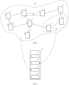
- FIG. 2 illustrates a mesh jamming system 2 in accordance with the present disclosure.
- the mesh jamming system 2 comprises a plurality of jamming nodes 1 according to the first aspect or any of its implementations.
- the mesh jamming system 2 further comprises a designated control node 21, being configured to define a configuration setting for the respective jamming node 1, and to define a jamming job 4 for at least one of the plurality of jamming nodes 1.
- the designated control node 21 may comprise a Command & Control (C2) station.
- C2 Command & Control
- Command & Control may refer to the exercise of authority and direction by a properly designated individual over assigned resources in the accomplishment of a common goal/mission.
- configuration of the mesh jamming system 2 may still be based on a C2 in the traditional way, involving the limitations mentioned above.
- An alternative approach to overcome the area jamming limitations is to have a plurality of jamming nodes 1 operate in a mesh.
- Each jamming node 1 has the capability to create jamming jobs 4 and distribute them to other nearby jamming nodes 1 that it is connected with.
- a nearby downstream jamming node 1 in No Job state S2 can connect to the first jamming node 1, retrieve said jamming job 4 from the first jamming node 1, and execute said jamming job 4. Subsequent downstream jamming nodes 1 can be setup similarly.
- the respective downstream jamming node 1 does not depend on a C2 for management and control but on one or more upstream jamming nodes 1 to which it can connect and synchronize to. That is to say, each jamming node 1 may have management and control from more than one source which increases redundancy. While each jamming node 1 may have a distance limit D from the next nearest upstream jamming node 1, the total area coverage can easily be scaled up through the mesh.
- the respective jamming node 1 may connect to the jamming nodes 1 in the mesh, retrieve the jamming jobs 4 from already operational jamming nodes 1 and switch to jamming operation itself.
- the designated control node 21 may further be configured to define a number of jamming jobs 4 described next.
- FIG. 3 illustrates a jamming job 4 data structure in accordance with the present disclosure.
- the respective jamming job 4 may be associated with job parameters 41.
- jamming jobs 4 may be differentiated by the respective job parameters 41.
- different sections of a mesh jamming system 2 may execute a same or different jamming jobs 4.
- the respective jamming job 4 may further be associated with at least one jammer identifier 13 of the plurality of jamming nodes 1.
- the plurality of jamming nodes 1 may retrieve a plurality of jamming jobs 4 and selectively execute these jamming jobs 4 depending on a match of the respective jammer identifier 13 of the jamming node 1 and the at least one jammer identifier 13 of the jamming job 4.
- the at least one jammer identifier 13 of the jamming job 4 may be used to assign jamming jobs 4 to particular sections of the mesh jamming system 2.
- the respective jamming job 4 may further be associated with the mesh identifier 42 being indicative of the mesh jamming system 2.
- the plurality of jamming nodes 1 may selectively retrieve a plurality of jamming jobs 4 depending on a match of the respective mesh identifier 42 of the jamming node 1 and the mesh identifier 42 of the jamming job 4.
- the mesh identifier 42 may be used to assign jamming jobs 4 to whole mesh jamming systems 2.
- the respective jamming job 4 may further be associated with a time stamp 43 being indicative of a timeliness of the respective jamming job 4.
- a time stamp 43 being indicative of a timeliness of the respective jamming job 4.
- jamming jobs 4 can be timed so that the most recent one would be the one to execute.
Landscapes
- Engineering & Computer Science (AREA)
- Computer Networks & Wireless Communication (AREA)
- Signal Processing (AREA)
- Mobile Radio Communication Systems (AREA)
- Radar Systems Or Details Thereof (AREA)
Abstract
Description
- The present disclosure relates to radio jamming and, in particular, to a jamming node and a mesh jamming system.
- Radio jamming, i.e., a deliberate use of electromagnetic energy to degrade or disrupt communications, typically involves a single jamming node having a single area of coverage.
- For a wider area coverage, a plurality of jamming nodes may be provided, jointly being controlled by a designated control node for synchronization and function and respectively located in proximity of the designated control node, in accordance with a maximum distance from the designated control node. The resulting star topology limits a total area coverage for the plurality of jammers.
- For redundancy, there may be a backup control node, but there remains one central control node in operation at any point in time. The dependency on the central control node implies a single point of failure for jamming operation.
- In view of the above-mentioned drawbacks and limitations, the present disclosure aims to improve the radio jamming of the background art.
- The objective is achieved by the embodiments as defined by the appended independent claims. Preferred embodiments are set forth in the dependent claims and in the following description and drawings.
- A first aspect of the present disclosure relates to a jamming node, comprising a wireless interface and a stateful control unit. The wireless interface is configured to communicate with a number of further jamming nodes within a defined maximum distance. The stateful control unit is configured in a No Job state to retrieve a jamming job from an upstream jamming node of the further jamming nodes, the upstream jamming node being in a Mesh Ready state, and to proceed to a Loaded Job state. The control unit is configured in the Loaded Job state to proceed to either the Mesh Ready state or a Solo state in accordance with a configuration setting. The control unit is configured in the Mesh Ready state to execute the jamming job, and to provide the jamming job to a downstream jamming node of the further jamming nodes, the downstream jamming node being in the No Job state.
- The configuration setting may be retrievable from a remote control device or a designated control node.
- The configuration setting may comprise a frequency list being indicative of frequencies to be excluded from jamming.
- The remote control device may comprise a smart device being configured to execute a remote control application.
- The stateful control unit may further be configured in the Mesh Ready state to execute the jamming job at a prompting of at least one of: the remote control device, a timer, and the upstream jamming node.
- The stateful control unit may further be configured in the Solo state to execute the jamming job.
- The stateful control unit may further be configured in the Solo state to execute the jamming job at a prompting of at least one of: the remote control device, and a timer.
- The stateful control unit may further be configured in a Configure state to proceed to the No Job state at the prompting of the remote control device, to retrieve the jamming job from the remote control device or the designated control node, and to proceed to the Loaded Job state. The stateful control unit may further be configured in the Mesh Ready state and in the Solo state to proceed to the Configure state at the prompting of the remote control device or the designated control node.
- The jamming node may further comprise a jammer identifier. The stateful control unit may further be configured in the Mesh Ready state and in the Solo state to execute the jamming job, when associated with the jammer identifier, at the prompting of the remote control device or the timer.
- The jamming node may further comprise a mesh identifier. The stateful control unit may further be configured in the No Job state to retrieve the jamming job from the upstream jamming node of the further jamming nodes, the upstream jamming node being in the Mesh Ready state and being associated with the mesh identifier, and to proceed to the Loaded Job state.
- The stateful control unit may further be configured in the Configure state to proceed to an Inoperative state at the prompting of the remote control device or the designated control node, and in the Inoperative state to proceed to the Configure state upon activation.
- A second aspect of the present disclosure relates to a mesh jamming system, comprising a plurality of jamming nodes according to the first aspect or any of its implementations and a designated control node. The designated control node may be configured to define a configuration setting for the respective jamming node and to define a jamming job for at least one of the plurality of jamming nodes.
- The designated control node may further be configured to define a number of jamming jobs being differentiated by job parameters. The respective jamming job may be associated with at least one jammer identifier of the plurality of jamming nodes.
- The respective jamming job may be associated with the mesh identifier being indicative of the mesh jamming system.
- The respective jamming job may be associated with a time stamp being indicative of a timeliness of the respective jamming job.
- The present disclosure provides a jamming node and a mesh jamming system.
- By using mesh jamming, the problem of large size, weight and power for large area coverage deployment can be mitigated significantly. It prevents a single point of failure, although it still does not have complete redundancy. With such topology, jammers can be made smaller and very mobile. It can serve many use cases, extending beyond military operations where C2 is a commonality. It significantly enhances flexibility and use, especially in an urban environment.
- In addition, an area coverage is increased without increasing transmit power, and flexibility and resiliency are also increased.
- The above-described aspects and implementations will now be explained with reference to the accompanying drawings, in which the same or similar reference numerals designate the same or similar elements.
- The features of these aspects and implementations may be combined with each other unless specifically stated otherwise.
- The drawings are to be regarded as being schematic representations, and elements illustrated in the drawings are not necessarily shown to scale. Rather, the various elements are represented such that their function and general purpose become apparent to those skilled in the art.
-
FIG. 1 illustrates a jamming node in accordance with the present disclosure; -
FIG. 2 illustrates a mesh jamming system in accordance with the present disclosure; and -
FIG. 3 illustrates a jamming job data structure in accordance with the present disclosure. -
FIG. 1 illustrates ajamming node 1 in accordance with the present disclosure. - The
jamming node 1 comprises awireless interface 11 and astateful control unit 12. - The
jamming node 1 may further comprise a jammer identifier 13 (not shown). - The
jamming node 1 may further comprise a mesh identifier 42 (seeFIG. 3 ). - As indicated in
FIG. 1 , thewireless interface 11 may be in electrical communication with an antenna or antenna system. - The
wireless interface 11 may be configured to communicate with aremote control device 3. For example, theremote control device 3 may comprise a smart device being configured to execute a remote control application. - A smart device as used herein may refer to an electronic device being configured to communicate to other electronic devices via one or more wireless protocols and to operate interactively and autonomously. For example, a smart device may be a smart phone, a phablet (phone/tablet) device, a tablet device, a laptop device, etc.
- The
wireless interface 11 is configured to communicate with a number offurther jamming nodes 1 within a defined maximum distance D (see -
FIG. 2 ). For example, the maximum distance D may be limited by a maximum transmit power of thewireless interface 11. - As indicated by a state diagram in the speech bubble at the bottom of
FIG. 1 , thestateful control unit 12 may be configured to run a finite state machine. The example ofFIG. 1 illustrates states S0-S5 and state transitions denoted by circles and arrows, respectively. - In an Inoperative state S0, the
stateful control unit 12 - may be configured to proceed to a Configure state S1 upon activation, for example by operating personnel.
- In the Configure state S1, the
stateful control unit 12 - may be configured to proceed to the Inoperative state S0 at the prompting of the
remote control device 3 or a designated control node 21 (seeFIG. 2 ), - may further be configured to retrieve a
jamming job 4 from theremote control device 3 or the designated control node 21, and to proceed to the Loaded Job state S3. In this case, the jammingjob 4 may be provided to the (upstream) jammingnode 1 by operating personnel. - may further be configured to proceed to a No Job state S2 at the prompting of the
remote control device 3. - In the No Job state S2, the
stateful control unit 12 - is configured to retrieve a
jamming job 4 from anupstream jamming node 1 of thefurther jamming nodes 1, whichupstream jamming node 1 is in a Mesh Ready state S4, and to proceed to a Loaded Job state S3, - may further be configured to retrieve the jamming
job 4 from theupstream jamming node 1 of thefurther jamming nodes 1, whichupstream jamming node 1 is in the Mesh Ready state S4 and is associated with the mesh identifier 42, and to proceed to the Loaded Job state S3. - The designation as the
upstream jamming node 1 is to indicate a direction of information flow. - In the Loaded Job state S3, the
control unit 12 - is configured to proceed to either a Mesh Ready state S4 or a Solo state S5 in accordance with a configuration setting of the jamming
node 1. - The configuration setting may be retrievable from the remote control device 3 (see
FIG. 1 ) or the designated control node 21 (seeFIG. 2 ) . - In particular, the configuration setting may comprise a frequency list being indicative of frequencies to be excluded from jamming.
- For communication among jamming
nodes 1, doing job transfers and coordinating states, certain frequencies have to be excluded from jamming to perform this kind of communication. Therefore, a shared restricted frequency list has to be pre-defined for therespective jamming node 1. More than one frequency can be used for this purpose so that it falls outside of the target frequencies that can be changed. An algorithm can be employed to preselect the communication frequency for use depending on the target frequencies in the job so that the jammingnodes 1 do not disable themselves. - In the Mesh Ready state S4, the
stateful control unit 12 - is configured to execute the jamming
job 4, - is configured to provide the
jamming job 4 to adownstream jamming node 1 of thefurther jamming nodes 1, whichdownstream jamming node 1 is in a No Job state S2. - may further be configured to execute the jamming
job 4 at a prompting of at least one of: theremote control device 3, a timer, and theupstream jamming node 1. That is to say, the jammingnode 1 can be made to transmit on a trigger source. For the remote control trigger, only one jamming node 1needs to be triggered because theother jamming nodes 1 in the mesh can take their cue from the triggered jammingnode 1 and then execute theirjamming job 4. - may further be configured to execute the jamming
job 4, when associated with the jammer identifier 13, at the prompting of theremote control device 3 or the timer. - may further be configured to proceed to the Configure state S1 at the prompting of the
remote control device 3 or the designated control node 21. - The designation as the
downstream jamming node 1 is to indicate a direction of information flow. - In the Solo state S5, the
stateful control unit 12 - may be configured to execute the jamming
job 4, - may further be configured to execute the jamming
job 4 at a prompting of at least one of: theremote control device 3, and a timer (similar to the timer in the Mesh Ready state S4), and - may further be configured to execute the jamming
job 4, when associated with the jammer identifier 13, at the prompting of theremote control device 3 or the timer. - may further be configured to proceed to the Configure state S1 at the prompting of the
remote control device 3 or the designated control node 21. - As such, is the Solo State the
respective jamming node 1 does not connect to the mesh but load its individual job and is run and controlled independently. -
FIG. 2 illustrates amesh jamming system 2 in accordance with the present disclosure. - The
mesh jamming system 2 comprises a plurality of jammingnodes 1 according to the first aspect or any of its implementations. - The
mesh jamming system 2 further comprises a designated control node 21, being configured to define a configuration setting for therespective jamming node 1, and to define ajamming job 4 for at least one of the plurality of jammingnodes 1. - In particular, the designated control node 21 may comprise a Command & Control (C2) station.
- Command & Control may refer to the exercise of authority and direction by a properly designated individual over assigned resources in the accomplishment of a common goal/mission.
- As such, configuration of the
mesh jamming system 2 may still be based on a C2 in the traditional way, involving the limitations mentioned above. - An alternative approach to overcome the area jamming limitations is to have a plurality of jamming
nodes 1 operate in a mesh. - Each jamming
node 1 has the capability to create jammingjobs 4 and distribute them to othernearby jamming nodes 1 that it is connected with. - There will be a first
upstream jamming node 1 in in Mesh Ready state S4 that is configured and ready to execute ajamming job 4. - A nearby
downstream jamming node 1 in No Job state S2 can connect to thefirst jamming node 1, retrieve said jammingjob 4 from thefirst jamming node 1, and execute said jammingjob 4. Subsequentdownstream jamming nodes 1 can be setup similarly. - The respective
downstream jamming node 1 does not depend on a C2 for management and control but on one or moreupstream jamming nodes 1 to which it can connect and synchronize to. That is to say, each jammingnode 1 may have management and control from more than one source which increases redundancy. While each jammingnode 1 may have a distance limit D from the next nearestupstream jamming node 1, the total area coverage can easily be scaled up through the mesh. - For as long as the
respective jamming node 1 forms part of themesh jamming system 2, it may connect to the jammingnodes 1 in the mesh, retrieve the jammingjobs 4 from alreadyoperational jamming nodes 1 and switch to jamming operation itself. - The designated control node 21 may further be configured to define a number of jamming
jobs 4 described next. -
FIG. 3 illustrates a jammingjob 4 data structure in accordance with the present disclosure. - The
respective jamming job 4 may be associated with job parameters 41. In particular, jammingjobs 4 may be differentiated by the respective job parameters 41. As such, different sections of amesh jamming system 2 may execute a same ordifferent jamming jobs 4. - The
respective jamming job 4 may further be associated with at least one jammer identifier 13 of the plurality of jammingnodes 1. For example, the plurality of jammingnodes 1 may retrieve a plurality of jammingjobs 4 and selectively execute these jammingjobs 4 depending on a match of the respective jammer identifier 13 of the jammingnode 1 and the at least one jammer identifier 13 of the jammingjob 4. As indicated inFIG. 3 , the at least one jammer identifier 13 of the jammingjob 4 may be used to assign jammingjobs 4 to particular sections of themesh jamming system 2. - The
respective jamming job 4 may further be associated with the mesh identifier 42 being indicative of themesh jamming system 2. For example, the plurality of jammingnodes 1 may selectively retrieve a plurality of jammingjobs 4 depending on a match of the respective mesh identifier 42 of the jammingnode 1 and the mesh identifier 42 of the jammingjob 4. As indicated inFIG. 3 , the mesh identifier 42 may be used to assign jammingjobs 4 to wholemesh jamming systems 2. - The
respective jamming job 4 may further be associated with a time stamp 43 being indicative of a timeliness of therespective jamming job 4. In order to know which is the latest action to follow in the mesh, jammingjobs 4 can be timed so that the most recent one would be the one to execute.
Claims (15)
- A jamming node (1), comprisinga wireless interface (11), being configured
o to communicate with a number of further jamming nodes (1) within a defined maximum distance (D); anda stateful control unit (12), being configured∘ in a No Job state (S2):
▪ to retrieve a jamming job (4) from an upstream jamming node (1) of the further jamming nodes (1), the upstream jamming node (1) being in a Mesh Ready state (S4), and to proceed to a Loaded Job state (S3);∘ in the Loaded Job state (S3):
▪ to proceed to either the Mesh Ready state (S4) or a Solo state (S5) in accordance with a configuration setting;∘ in the Mesh Ready state (S4):▪ to execute the jamming job (4); and▪ to provide the jamming job (4) to a downstream jamming node (1) of the further jamming nodes (1), the downstream jamming node (1) being in a No Job state (S2) . - The jamming node (1) of claim 1,
the configuration setting being retrievable from a remote control device (3) or a designated control node (21). - The jamming node (1) of claim 2,
the configuration setting comprising
a frequency list being indicative of frequencies to be excluded from jamming. - The jamming node (1) of any one of the preceding claims, the remote control device (3) comprising
a smart device being configured to execute a remote control application. - The jamming node (1) of any one of the preceding claims, the stateful control unit (12) further being configured
∘ in the Mesh Ready state (S4):
▪ to execute the jamming job (4) at a prompting of at least one of: the remote control device (3), a timer, and the upstream jamming node (1). - The jamming node (1) of any one of the preceding claims, the stateful control unit (12) further being configured
∘ in the Solo state (S5):
▪ to execute the jamming job (4). - The jamming node (1) of claim 6,
the stateful control unit (12) further being configured
∘ in the Solo state (S5):
▪ to execute the jamming job (4) at a prompting of at least one of: the remote control device (3), and a timer. - The jamming node (1) of any one of the preceding claims, the stateful control unit (12) further being configured∘ in a Configure state (S1):▪ to proceed to the No Job state (S2) at the prompting of the remote control device (3);▪ to retrieve the jamming job (4) from the remote control device (3) or the designated control node (21), and to proceed to the Loaded Job state (S3); and∘ in the Mesh Ready state (S4) and in the Solo state (S5):
▪ to proceed to the Configure state (S1) at the prompting of the remote control device (3) or the designated control node (21). - The jamming node (1) of any one of the preceding claims, further comprising
a jammer identifier (13);
the stateful control unit (12) further being configured
∘ in the Mesh Ready state (S4) and in the Solo state (S5):
▪ to execute the jamming job (4), when associated with the jammer identifier (13), at the prompting of the remote control device (3) or the timer. - The jamming node (1) of any one of the preceding claims, further comprisinga mesh identifier (42);the stateful control unit (12) further being configured
∘ in the No Job state (S2):
▪ to retrieve the jamming job (4) from the upstream jamming node (1) of the further jamming nodes (1), the upstream jamming node (1) being in the Mesh Ready state (S4) and being associated with the mesh identifier (42), and to proceed to the Loaded Job state (S3). - The jamming node (1) of any one of the preceding claims,
the stateful control unit (12) further being configured∘ in the Configure state (S1):
▪ to proceed to an Inoperative state (S0) at the prompting of the remote control device (3) or the designated control node (21); and∘ in the Inoperative state (S0):
▪ to proceed to the Configure state (S1) upon activation. - A mesh jamming system (2), comprisinga plurality of jamming nodes (1) according to any one of the preceding claims; anda designated control node (21), being configuredo to define a configuration setting for the respective jamming node (1); ando to define a jamming job (4) for at least one of the plurality of jamming nodes (1).
- The mesh jamming system (2) of claim 12,the designated control node (21) further being configured
o to define a number of jamming jobs (4) being differentiated by job parameters (41);the respective jamming job (4) being associated with at least one jammer identifier (13) of the plurality of jamming nodes (1). - The mesh jamming system (2) of claim 12 or claim 13,
the respective jamming job (4) being associated with the mesh identifier (42) being indicative of the mesh jamming system (2). - The mesh jamming system (2) of any one of the claims 12 to 14,
the respective jamming job (4) being associated with a time stamp (43) being indicative of a timeliness of the respective jamming job (4) .
Priority Applications (1)
| Application Number | Priority Date | Filing Date | Title |
|---|---|---|---|
| EP22153801.0A EP4221001B1 (en) | 2022-01-28 | 2022-01-28 | Jamming node and mesh jamming system |
Applications Claiming Priority (1)
| Application Number | Priority Date | Filing Date | Title |
|---|---|---|---|
| EP22153801.0A EP4221001B1 (en) | 2022-01-28 | 2022-01-28 | Jamming node and mesh jamming system |
Publications (2)
| Publication Number | Publication Date |
|---|---|
| EP4221001A1 true EP4221001A1 (en) | 2023-08-02 |
| EP4221001B1 EP4221001B1 (en) | 2025-09-17 |
Family
ID=80122369
Family Applications (1)
| Application Number | Title | Priority Date | Filing Date |
|---|---|---|---|
| EP22153801.0A Active EP4221001B1 (en) | 2022-01-28 | 2022-01-28 | Jamming node and mesh jamming system |
Country Status (1)
| Country | Link |
|---|---|
| EP (1) | EP4221001B1 (en) |
Citations (3)
| Publication number | Priority date | Publication date | Assignee | Title |
|---|---|---|---|---|
| US20140206279A1 (en) * | 2013-01-22 | 2014-07-24 | Eden Rock Communications, Llc | Method and system for intelligent jamming signal generation |
| US20160105254A1 (en) * | 2013-04-09 | 2016-04-14 | Raytheon Company | Methods and apparatuses for allocating electromagnetic-spectrum jamming assets |
| US20200272827A1 (en) * | 2015-09-23 | 2020-08-27 | Dedrone Holdings, Inc. | Identifying, tracking, and disrupting unmanned aerial vehicles |
-
2022
- 2022-01-28 EP EP22153801.0A patent/EP4221001B1/en active Active
Patent Citations (3)
| Publication number | Priority date | Publication date | Assignee | Title |
|---|---|---|---|---|
| US20140206279A1 (en) * | 2013-01-22 | 2014-07-24 | Eden Rock Communications, Llc | Method and system for intelligent jamming signal generation |
| US20160105254A1 (en) * | 2013-04-09 | 2016-04-14 | Raytheon Company | Methods and apparatuses for allocating electromagnetic-spectrum jamming assets |
| US20200272827A1 (en) * | 2015-09-23 | 2020-08-27 | Dedrone Holdings, Inc. | Identifying, tracking, and disrupting unmanned aerial vehicles |
Also Published As
| Publication number | Publication date |
|---|---|
| EP4221001B1 (en) | 2025-09-17 |
Similar Documents
| Publication | Publication Date | Title |
|---|---|---|
| US7430415B2 (en) | Real-time programming of electronic radio system resource assets | |
| US6901275B1 (en) | Communication system, and communication device and communication method for use in the communication system | |
| US20170353960A1 (en) | Systems and methods for dynamically allocating wireless service resources consonant with service demand density | |
| US20020065053A1 (en) | Dual channel redundant fixed wireless network link, and method therefore | |
| US20060141954A1 (en) | Slice based architecture for a multifunction radio | |
| CN109714399A (en) | Method for pushing and device, storage medium, the electronic device of notification message | |
| US20040192376A1 (en) | Multi-beam satellite collocation and channel power allocation | |
| US11877199B2 (en) | Base station management method, base station management apparatus and program | |
| CN104079330B (en) | MIMO-phased array antenna device, system and implementation method thereof | |
| EP1187353A2 (en) | Transceiver-processor building block for electronic radio systems | |
| US20210226633A1 (en) | Method and system for providing wireless fpga programming download via a wireless communication block | |
| US20220208009A1 (en) | Flight management system and flight management method | |
| CN105182993A (en) | Flight control method and device | |
| EP4221001B1 (en) | Jamming node and mesh jamming system | |
| US20110092244A1 (en) | Ad-hoc wireless communication method using sector antenna, recovery method in ad-hoc wireless communication and ad-hoc wireless communication system | |
| US12439282B2 (en) | Providing continuous service in wireless communication network | |
| EP2654334B1 (en) | Phased array antenna and assignment method | |
| US10833722B1 (en) | Method and system for providing a programmable logic device having a configurable wireless communication block field | |
| US11196156B2 (en) | Fixed wireless systems and methods incorporating a beam steering antenna | |
| CN110167038B (en) | Method for topology determination in a mobile radio station and mobile radio station | |
| US9621259B2 (en) | Ad hoc configurable TDMA datalink | |
| CN109861715B (en) | A base station, base station system and communication network | |
| KR101141603B1 (en) | Method and apparatus for providing remote controlling for remote robot management in multi frequency environment | |
| Xia et al. | UAV access control for urban emergency communications in space-air-ground integrated networks | |
| CN105472689A (en) | MAC layer neighbor node discovery method and platform based on MANET network |
Legal Events
| Date | Code | Title | Description |
|---|---|---|---|
| PUAI | Public reference made under article 153(3) epc to a published international application that has entered the european phase |
Free format text: ORIGINAL CODE: 0009012 |
|
| STAA | Information on the status of an ep patent application or granted ep patent |
Free format text: STATUS: THE APPLICATION HAS BEEN PUBLISHED |
|
| STAA | Information on the status of an ep patent application or granted ep patent |
Free format text: STATUS: REQUEST FOR EXAMINATION WAS MADE |
|
| AK | Designated contracting states |
Kind code of ref document: A1 Designated state(s): AL AT BE BG CH CY CZ DE DK EE ES FI FR GB GR HR HU IE IS IT LI LT LU LV MC MK MT NL NO PL PT RO RS SE SI SK SM TR |
|
| 17P | Request for examination filed |
Effective date: 20230720 |
|
| RBV | Designated contracting states (corrected) |
Designated state(s): AL AT BE BG CH CY CZ DE DK EE ES FI FR GB GR HR HU IE IS IT LI LT LU LV MC MK MT NL NO PL PT RO RS SE SI SK SM TR |
|
| GRAP | Despatch of communication of intention to grant a patent |
Free format text: ORIGINAL CODE: EPIDOSNIGR1 |
|
| STAA | Information on the status of an ep patent application or granted ep patent |
Free format text: STATUS: GRANT OF PATENT IS INTENDED |
|
| INTG | Intention to grant announced |
Effective date: 20250624 |
|
| GRAS | Grant fee paid |
Free format text: ORIGINAL CODE: EPIDOSNIGR3 |
|
| GRAA | (expected) grant |
Free format text: ORIGINAL CODE: 0009210 |
|
| STAA | Information on the status of an ep patent application or granted ep patent |
Free format text: STATUS: THE PATENT HAS BEEN GRANTED |
|
| P01 | Opt-out of the competence of the unified patent court (upc) registered |
Free format text: CASE NUMBER: UPC_APP_2042_4221001/2025 Effective date: 20250731 |
|
| AK | Designated contracting states |
Kind code of ref document: B1 Designated state(s): AL AT BE BG CY CZ DE DK EE ES FI FR GB GR HR HU IS IT LT LU LV MC MK MT NL NO PL PT RO RS SE SI SK SM TR |
|
| RBV | Designated contracting states (corrected) |
Designated state(s): AL AT BE BG CY CZ DE DK EE ES FI FR GB GR HR HU IS IT LT LU LV MC MK MT NL NO PL PT RO RS SE SI SK SM TR |
|
| REG | Reference to a national code |
Ref country code: GB Ref legal event code: FG4D |
|
| REG | Reference to a national code |
Ref country code: DE Ref legal event code: R096 Ref document number: 602022021427 Country of ref document: DE |
|
| PG25 | Lapsed in a contracting state [announced via postgrant information from national office to epo] |
Ref country code: NO Free format text: LAPSE BECAUSE OF FAILURE TO SUBMIT A TRANSLATION OF THE DESCRIPTION OR TO PAY THE FEE WITHIN THE PRESCRIBED TIME-LIMIT Effective date: 20251217 |
|
| REG | Reference to a national code |
Ref country code: LT Ref legal event code: MG9D |
|
| PG25 | Lapsed in a contracting state [announced via postgrant information from national office to epo] |
Ref country code: FI Free format text: LAPSE BECAUSE OF FAILURE TO SUBMIT A TRANSLATION OF THE DESCRIPTION OR TO PAY THE FEE WITHIN THE PRESCRIBED TIME-LIMIT Effective date: 20250917 |
|
| PG25 | Lapsed in a contracting state [announced via postgrant information from national office to epo] |
Ref country code: HR Free format text: LAPSE BECAUSE OF FAILURE TO SUBMIT A TRANSLATION OF THE DESCRIPTION OR TO PAY THE FEE WITHIN THE PRESCRIBED TIME-LIMIT Effective date: 20250917 |
|
| PG25 | Lapsed in a contracting state [announced via postgrant information from national office to epo] |
Ref country code: GR Free format text: LAPSE BECAUSE OF FAILURE TO SUBMIT A TRANSLATION OF THE DESCRIPTION OR TO PAY THE FEE WITHIN THE PRESCRIBED TIME-LIMIT Effective date: 20251218 |
|
| PG25 | Lapsed in a contracting state [announced via postgrant information from national office to epo] |
Ref country code: SE Free format text: LAPSE BECAUSE OF FAILURE TO SUBMIT A TRANSLATION OF THE DESCRIPTION OR TO PAY THE FEE WITHIN THE PRESCRIBED TIME-LIMIT Effective date: 20250917 |
|
| REG | Reference to a national code |
Ref country code: NL Ref legal event code: MP Effective date: 20250917 |
|
| PG25 | Lapsed in a contracting state [announced via postgrant information from national office to epo] |
Ref country code: LV Free format text: LAPSE BECAUSE OF FAILURE TO SUBMIT A TRANSLATION OF THE DESCRIPTION OR TO PAY THE FEE WITHIN THE PRESCRIBED TIME-LIMIT Effective date: 20250917 |
|
| PG25 | Lapsed in a contracting state [announced via postgrant information from national office to epo] |
Ref country code: BG Free format text: LAPSE BECAUSE OF FAILURE TO SUBMIT A TRANSLATION OF THE DESCRIPTION OR TO PAY THE FEE WITHIN THE PRESCRIBED TIME-LIMIT Effective date: 20250917 |
|
| PG25 | Lapsed in a contracting state [announced via postgrant information from national office to epo] |
Ref country code: RS Free format text: LAPSE BECAUSE OF FAILURE TO SUBMIT A TRANSLATION OF THE DESCRIPTION OR TO PAY THE FEE WITHIN THE PRESCRIBED TIME-LIMIT Effective date: 20251217 |
|
| PG25 | Lapsed in a contracting state [announced via postgrant information from national office to epo] |
Ref country code: NL Free format text: LAPSE BECAUSE OF FAILURE TO SUBMIT A TRANSLATION OF THE DESCRIPTION OR TO PAY THE FEE WITHIN THE PRESCRIBED TIME-LIMIT Effective date: 20250917 |
|
| REG | Reference to a national code |
Ref country code: AT Ref legal event code: MK05 Ref document number: 1839291 Country of ref document: AT Kind code of ref document: T Effective date: 20250917 |
|
| PG25 | Lapsed in a contracting state [announced via postgrant information from national office to epo] |
Ref country code: SM Free format text: LAPSE BECAUSE OF FAILURE TO SUBMIT A TRANSLATION OF THE DESCRIPTION OR TO PAY THE FEE WITHIN THE PRESCRIBED TIME-LIMIT Effective date: 20250917 |
|
| PGFP | Annual fee paid to national office [announced via postgrant information from national office to epo] |
Ref country code: GB Payment date: 20260122 Year of fee payment: 5 |
|
| PG25 | Lapsed in a contracting state [announced via postgrant information from national office to epo] |
Ref country code: ES Free format text: LAPSE BECAUSE OF FAILURE TO SUBMIT A TRANSLATION OF THE DESCRIPTION OR TO PAY THE FEE WITHIN THE PRESCRIBED TIME-LIMIT Effective date: 20250917 |
|
| PGFP | Annual fee paid to national office [announced via postgrant information from national office to epo] |
Ref country code: DE Payment date: 20260120 Year of fee payment: 5 |
|
| PG25 | Lapsed in a contracting state [announced via postgrant information from national office to epo] |
Ref country code: AT Free format text: LAPSE BECAUSE OF FAILURE TO SUBMIT A TRANSLATION OF THE DESCRIPTION OR TO PAY THE FEE WITHIN THE PRESCRIBED TIME-LIMIT Effective date: 20250917 |
|
| PG25 | Lapsed in a contracting state [announced via postgrant information from national office to epo] |
Ref country code: IT Free format text: LAPSE BECAUSE OF FAILURE TO SUBMIT A TRANSLATION OF THE DESCRIPTION OR TO PAY THE FEE WITHIN THE PRESCRIBED TIME-LIMIT Effective date: 20250917 |
|
| PG25 | Lapsed in a contracting state [announced via postgrant information from national office to epo] |
Ref country code: IS Free format text: LAPSE BECAUSE OF FAILURE TO SUBMIT A TRANSLATION OF THE DESCRIPTION OR TO PAY THE FEE WITHIN THE PRESCRIBED TIME-LIMIT Effective date: 20260117 |
|
| PGFP | Annual fee paid to national office [announced via postgrant information from national office to epo] |
Ref country code: FR Payment date: 20260128 Year of fee payment: 5 |
|
| PG25 | Lapsed in a contracting state [announced via postgrant information from national office to epo] |
Ref country code: PT Free format text: LAPSE BECAUSE OF FAILURE TO SUBMIT A TRANSLATION OF THE DESCRIPTION OR TO PAY THE FEE WITHIN THE PRESCRIBED TIME-LIMIT Effective date: 20260119 Ref country code: CZ Free format text: LAPSE BECAUSE OF FAILURE TO SUBMIT A TRANSLATION OF THE DESCRIPTION OR TO PAY THE FEE WITHIN THE PRESCRIBED TIME-LIMIT Effective date: 20250917 |
|
| PG25 | Lapsed in a contracting state [announced via postgrant information from national office to epo] |
Ref country code: PL Free format text: LAPSE BECAUSE OF FAILURE TO SUBMIT A TRANSLATION OF THE DESCRIPTION OR TO PAY THE FEE WITHIN THE PRESCRIBED TIME-LIMIT Effective date: 20250917 |
|
| PG25 | Lapsed in a contracting state [announced via postgrant information from national office to epo] |
Ref country code: EE Free format text: LAPSE BECAUSE OF FAILURE TO SUBMIT A TRANSLATION OF THE DESCRIPTION OR TO PAY THE FEE WITHIN THE PRESCRIBED TIME-LIMIT Effective date: 20250917 Ref country code: SK Free format text: LAPSE BECAUSE OF FAILURE TO SUBMIT A TRANSLATION OF THE DESCRIPTION OR TO PAY THE FEE WITHIN THE PRESCRIBED TIME-LIMIT Effective date: 20250917 |
|
| REG | Reference to a national code |
Ref country code: DE Ref legal event code: R097 Ref document number: 602022021427 Country of ref document: DE |
|
| PG25 | Lapsed in a contracting state [announced via postgrant information from national office to epo] |
Ref country code: LT Free format text: LAPSE BECAUSE OF FAILURE TO SUBMIT A TRANSLATION OF THE DESCRIPTION OR TO PAY THE FEE WITHIN THE PRESCRIBED TIME-LIMIT Effective date: 20250917 |
|
| PG25 | Lapsed in a contracting state [announced via postgrant information from national office to epo] |
Ref country code: DK Free format text: LAPSE BECAUSE OF FAILURE TO SUBMIT A TRANSLATION OF THE DESCRIPTION OR TO PAY THE FEE WITHIN THE PRESCRIBED TIME-LIMIT Effective date: 20250917 |
|
| PLBE | No opposition filed within time limit |
Free format text: ORIGINAL CODE: 0009261 |
|
| STAA | Information on the status of an ep patent application or granted ep patent |
Free format text: STATUS: NO OPPOSITION FILED WITHIN TIME LIMIT |