EP4220994A1 - Optical space communications transmission and reception terminal and optical space communications system - Google Patents
Optical space communications transmission and reception terminal and optical space communications system Download PDFInfo
- Publication number
- EP4220994A1 EP4220994A1 EP20965086.0A EP20965086A EP4220994A1 EP 4220994 A1 EP4220994 A1 EP 4220994A1 EP 20965086 A EP20965086 A EP 20965086A EP 4220994 A1 EP4220994 A1 EP 4220994A1
- Authority
- EP
- European Patent Office
- Prior art keywords
- signal
- optical
- transmission
- output
- unit
- Prior art date
- Legal status (The legal status is an assumption and is not a legal conclusion. Google has not performed a legal analysis and makes no representation as to the accuracy of the status listed.)
- Granted
Links
Images




Classifications
-
- H—ELECTRICITY
- H04—ELECTRIC COMMUNICATION TECHNIQUE
- H04B—TRANSMISSION
- H04B10/00—Transmission systems employing electromagnetic waves other than radio-waves, e.g. infrared, visible or ultraviolet light, or employing corpuscular radiation, e.g. quantum communication
- H04B10/11—Arrangements specific to free-space transmission, i.e. transmission through air or vacuum
- H04B10/112—Line-of-sight transmission over an extended range
- H04B10/1123—Bidirectional transmission
-
- H—ELECTRICITY
- H04—ELECTRIC COMMUNICATION TECHNIQUE
- H04B—TRANSMISSION
- H04B10/00—Transmission systems employing electromagnetic waves other than radio-waves, e.g. infrared, visible or ultraviolet light, or employing corpuscular radiation, e.g. quantum communication
- H04B10/11—Arrangements specific to free-space transmission, i.e. transmission through air or vacuum
- H04B10/118—Arrangements specific to free-space transmission, i.e. transmission through air or vacuum specially adapted for satellite communication
Definitions
- the present disclosure relates to an optical space communications transmission and reception terminal and an optical space communications system.
- An optical fiber amplifier is used for a transceiver in optical space communications in order to improve reception sensitivity.
- the optical fiber amplifier is an amplifier that amplifies an optical signal coupled to the optical fiber.
- the optical signal amplified by the optical fiber amplifier is output to the optical transceiver.
- the optical transceiver extracts a clock signal corresponding to a symbol rate from the optical signal amplified by the optical fiber amplifier, and samples a received optical signal in synchronization with the extracted clock signal, thereby performing demodulation processing of the received optical signal.
- Non-Patent Literature 1 H. Hauschildt et al., "HydRON: High thRoughput Optical Network” 2019 IEEE International Conference on Space Optical Systems and Applications (ICSOS), Portland, OR, USA, 2019 .
- the optical transceiver cannot extract the clock signal from the received optical signal, and the communication is disabled.
- the conventional optical space communications system has a problem that communication cannot be recovered until a clock signal is extracted from the received optical signal amplified by the optical fiber amplifier after the SNR of the received optical signal is recovered. Note that the communication capacity of the optical space communications decreases as it takes time to recover the communications.
- the present disclosure solves the above problem, and an object of the present disclosure is to provide an optical space communications transmission and reception terminal and an optical space communications system capable of extracting a clock signal without waiting for recovery of an SNR of a received optical signal when communication is disabled due to a decrease in the SNR of the received optical signal caused by a loss generated when the optical signal is coupled to an optical fiber.
- An optical space communications transmission and reception terminal is an optical space communications transmission and reception terminal that performs bidirectional communication with a paired optical space communications transmission and reception terminal having a same configuration
- the optical space communications transmission and reception terminal includes: an optical transceiver to convert transmission data into a transmission optical signal modulated at a symbol rate synchronized with a transmission clock signal and output the transmission optical signal, and generate received data by demodulating and decoding a signal obtained by sampling a received optical signal at a cycle synchronized with a reception clock signal; an intensity modulation unit to generate a transmission optical signal obtained by superimposing a transmission clock signal on the transmission optical signal output from the optical transceiver and performing intensity modulation, and output the generated transmission optical signal; a transmission clock source to supply a common transmission clock signal to the optical transceiver and the intensity modulation unit; a fiber coupling unit to output an intensity-modulated transmission optical signal as collimated light and couple the input optical signal to an optical fiber; an optical fiber amplifier to amplify an optical signal coupled to the optical
- an angle sensor extracts a clock signal from an optical signal before being coupled to an optical fiber.
- the optical space communications transmission and reception terminal according to the present disclosure can extract the clock signal without waiting for recovery of the SNR of the received optical signal when communication is disabled due to a decrease in the SNR of the received optical signal caused by a loss generated when the optical signal is coupled to the optical fiber.
- the time until the communication is recovered can be shortened as compared with a case where the clock signal is extracted after the recovery of the SNR of the received optical signal.
- FIG. 1 is a block diagram illustrating a configuration of an optical space communications system 1 according to a first embodiment.
- the optical space communications system 1 is a system that performs communication using light propagating in space, and includes a pair of optical space communications transmission and reception terminals 1A.
- the optical space communications transmission and reception terminal 1A performs bidirectional communication with a paired optical space communications transmission and reception terminal 1A having the same configuration.
- FIG. 2 is a block diagram illustrating a configuration of the optical space communications transmission and reception terminal 1A.
- the optical space communications transmission and reception terminal 1A includes an optical transceiver 2, a transmission clock source 3, an intensity modulation unit 4, a fiber coupling unit 5, a tracking mirror 6, a beam splitter 7, an angle sensor 8, and an optical fiber amplifier 9.
- the optical transceiver 2, the intensity modulation unit 4, the fiber coupling unit 5, and the optical fiber amplifier 9 are connected to each other by an optical fiber. Further, the optical transceiver 2, the transmission clock source 3, the tracking mirror 6, and the angle sensor 8 are connected to each other by signal lines.
- the optical transceiver 2 converts transmission data (1) into a transmission optical signal (3) modulated at a symbol rate synchronized with a transmission clock signal (5) and outputs the transmission optical signal (3).
- the optical transceiver 2 samples a received optical signal (4) at a cycle synchronized with a reception clock signal (8), and generates received data (2) by demodulating and decoding the sampled signal.
- the transmission clock source 3 supplies a common transmission clock signal (5) to the optical transceiver 2 and the intensity modulation unit 4.
- the transmission clock source 3 outputs the transmission clock signal (5) having a frequency of 100 MHz
- the optical transceiver 2 multiplies the frequency of the transmission clock signal (5) by, for example, 20 to generate a transmission optical signal (3) modulated at a symbol rate of 2 GHz.
- the intensity modulation unit 4 superimposes the transmission clock signal (5) on the transmission optical signal (3) output from the optical transceiver 2 to generate an intensity-modulated transmission optical signal (3), and outputs an intensity-modulated transmission optical signal (6) to the fiber coupling unit 5.
- the intensity modulation unit 4 is an intensity modulator that superimposes the transmission clock signal (5) as a modulation signal on the transmission optical signal (3).
- the intensity modulation unit 4 prevents the modulation amplitude from being small and the intensity of the transmission optical signal (3) from greatly fluctuating. As a result, it is possible to reduce the influence of the fluctuation in the intensity of the intensity-modulated transmission optical signal (3) on the modulation and demodulation processing of the optical signal performed by the optical transceiver 2.
- the intensity modulation unit 4 has, for example, a configuration illustrated in FIG. 3.
- FIG. 3 is a block diagram illustrating a configuration example of the intensity modulation unit 4.
- the intensity modulation unit 4 includes an electro-optical converter 41 and an optical multiplexer 42.
- the electro-optical converter 41 is "E/O" in FIG. 3 .
- the electro-optical converter 41 converts the transmission clock signal (5) supplied from the transmission clock source 3 from an electrical signal into an optical signal.
- the optical multiplexer 42 multiplexes the transmission optical signal (3) output from the optical transceiver 2 and the transmission clock signal converted into the optical signal by the electro-optical converter 41.
- the transmission clock signal (5) is superimposed on the transmission optical signal (3), and the intensity of the transmission optical signal (3) is modulated.
- the transmission clock signal (5) converted into the optical signal is an optical signal having a wavelength different from that of the transmission optical signal (3).
- the transmission optical signal (6) intensity-modulated by the optical multiplexer 42 is a signal in which signals having different wavelengths are wavelength-multiplexed.
- the transmission optical signal (6) is output from the optical multiplexer 42 to the fiber coupling unit 5.
- the fiber coupling unit 5 outputs the transmission optical signal (6) intensity-modulated by the intensity modulation unit 4 as collimated light (parallel light), and couples the optical signal input from the tracking mirror 6 side to the optical fiber.
- the fiber coupling unit 5 includes a condensing lens that condenses the optical signal from the tracking mirror 6, and an optical system holder that holds the condensing lens and the optical fiber.
- the optical fiber held by the optical system holder is connected to the input side of the optical fiber amplifier 9.
- the optical signal from the tracking mirror 6 is condensed by the condensing lens and is incident on the optical fiber.
- the tracking mirror 6 When an optical signal transmitted from the paired optical space communications transmission and reception terminal 1A having the same configuration and propagating in the space is incident on the tracking mirror 6, the tracking mirror 6 outputs the incident optical signal toward the fiber coupling unit 5.
- the tracking mirror 6 includes at least a mirror unit that reflects incident light toward the fiber coupling unit 5 and a mirror drive unit that changes an angle of the mirror unit.
- the tracking mirror 6 When a propagation angle error (7) of the optical signal is input from the angle sensor 8, the tracking mirror 6 outputs an optical signal in which the propagation angle is corrected on the basis of the input propagation angle error (7).
- the propagation angle error (7) is a difference in propagation angle from the light beam coinciding with the optical axis.
- the mirror drive unit changes the angle of the mirror unit so as to eliminate the propagation angle error (7), thereby correcting the propagation angle of the optical signal incident on the tracking mirror 6.
- the optical signal whose propagation angle has been corrected is output to the side of the fiber coupling unit 5 via the beam splitter 7.
- the tracking mirror 6 When the transmission optical signal made into collimated light by the fiber coupling unit 5 is incident on the tracking mirror 6 via the beam splitter 7, the tracking mirror 6 outputs the incident collimated light to space. As a result, the transmission optical signal is transmitted to the paired optical space communications transmission and reception terminal 1A.
- the tracking mirror 6 corrects the propagation angle of the transmission optical signal (6) collimated by the fiber coupling unit 5 on the basis of the propagation angle error (7) detected by the angle sensor 8, and outputs the optical signal with the corrected propagation angle to space. As a result, the propagation direction of the optical signal transmitted to the paired optical space communications transmission and reception terminal 1A is compensated.
- the beam splitter 7 distributes a part of the optical signal propagating between the fiber coupling unit 5 and the tracking mirror 6 to the angle sensor 8. For example, the beam splitter 7 distributes a part of the transmission optical signal output from the fiber coupling unit 5 to the tracking mirror 6 to the angle sensor 8, and distributes a part of the transmission optical signal output from the tracking mirror 6 to the fiber coupling unit 5 to the angle sensor 8.
- the angle sensor 8 detects a propagation angle error (7) of the optical signal distributed by the beam splitter 7, and outputs the detected propagation angle error (7) to the tracking mirror 6. Further, the angle sensor 8 extracts a clock signal from the optical signal distributed by the beam splitter 7, and outputs the extracted clock signal to the optical transceiver 2 as a reception clock signal (8).
- the reception clock signal (8) is a sine wave signal of a clock frequency or a signal configured by repetition of a 0 (low) value and a 1 (high) value, and only the frequency is used as a clock.
- the angle sensor 8 has, for example, a configuration illustrated in FIG. 4.
- FIG. 4 is a block diagram illustrating a configuration of an example (1) of the angle sensor 8.
- the angle sensor 8 includes a lens 81, a four-divided light receiving element 82 (Hereinafter, it is referred to as a four-divided PD 82.), and a bandpass filter 83 (Hereinafter, it is referred to as a BPF 83.).
- the lens 81 condenses the optical signal distributed by the beam splitter 7 at the center of the light receiving surface of the four-divided PD 82.
- the four-divided PD 82 is a split type light receiving element having a light receiving surface divided into four light receiving areas.
- the BPF 83 is a bandpass filter having a frequency band of the transmission clock signal (5) in the paired optical space communications transmission and reception terminal 1A as a pass band.
- the center of the light receiving surface of the four-divided PD 82 is a position adjacent to all of the four light receiving areas.
- the four-divided PD 82 includes, for example, a calculation unit to calculate a propagation angle error (7) of the optical signal condensed on the light receiving surface on the basis of the intensity of the light received in the four light receiving areas.
- a propagation angle error (7) of the optical signal condensed on the light receiving surface on the basis of the intensity of the light received in the four light receiving areas.
- the calculation unit of the four-divided PD 82 calculates the deviation of the condensing position from the center of the light receiving surface on the basis of the difference in the intensity of the light received at each of the four light receiving areas and the total intensity of the light received at the four light receiving areas. Further, the calculation unit detects a propagation angle error (7) of the optical signal condensed on the light receiving surface on the basis of the deviation of the condensing position from the center of the light receiving surface.
- an optical signal transmitted from the optical space communications transmission and reception terminal 1A on the transmission side to the optical space communications transmission and reception terminal 1A on the reception side is an optical signal whose intensity fluctuates in synchronization with the transmission clock signal (5). That is, the fluctuation in the total intensity of the light received at the four light receiving areas on the light receiving surface of the four-divided PD 82 corresponds to the fluctuation in the intensity of the optical signal transmitted from the optical space communications transmission and reception terminal 1A on the transmission side.
- the BPF 83 can extract the clock signal by passing the frequency band of the transmission clock signal (5) in the optical space communications transmission and reception terminal 1A on the transmission side in a frequency band of the intensity fluctuation output from the four-divided PD 82.
- the clock signal extracted by the BPF 83 is output to the optical transceiver 2 as the reception clock signal (8).
- FIG. 5 is a block diagram illustrating a configuration of an example (2) of the angle sensor 8.
- the angle sensor 8 includes a beam splitter 84, a lens 85, a four-divided light receiving element 86 (Hereinafter, it is referred to as a four-divided PD 86.), a photoelectric converter 87, and a bandpass filter 88 (Hereinafter, it is referred to as a BPF 88.).
- the photoelectric converter 87 is an "O/E" in FIG. 5 .
- the beam splitter 84 distributes the optical signal divided by the beam splitter 7 into a four-divided PD 86 and a photoelectric converter 87.
- the lens 85 condenses the optical signal divided by the beam splitter 7 at the center of the light receiving surface of the four-divided PD 86.
- the four-divided PD 86 is a light receiving element having a light receiving surface divided into four light receiving areas.
- the center of the light receiving surface is a position adjacent to all of the four light receiving areas.
- the four-divided PD 86 includes a calculation unit that calculates a propagation angle error (7) of the optical signal condensed on the light receiving surface on the basis of the intensity of the light received in the four light receiving areas.
- the calculation unit of the four-divided PD 86 calculates the deviation of the condensing position from the center of the light receiving surface on the basis of the difference in the intensity of the light received by each of the four light receiving areas and the total intensity of the light received by the four light receiving areas. Further, the calculation unit detects a propagation angle error (7) of the optical signal condensed on the light receiving surface on the basis of the deviation of the condensing position from the center of the light receiving surface.
- the photoelectric converter 87 converts the optical signal divided by the beam splitter 7 into an electrical signal.
- the BPF 88 is a bandpass filter having a frequency band of the transmission clock signal (5) in the paired optical space communications transmission and reception terminal 1A as a pass band.
- a single mode fiber is used for the optical space communications transmission and reception terminal 1A.
- the single mode fiber is generally an optical fiber having a low influence of mode dispersion, and has a restricted core diameter.
- the four-divided PD 82, the four-divided PD 86, and the photoelectric converter 87 illustrated in FIGS. 4 and 5 have a light receiving area larger than the core diameter of the optical fiber without restriction on the light receiving surface. As a result, even if the wavefront of the input light is distorted, the angle sensor 8 suppresses a decrease in the intensity of the detected optical signal as compared with the intensity of the optical signal when coupled to the optical fiber.
- the angle sensor 8 can detect the intensity fluctuation from the optical signal before being coupled to the optical fiber, even in a case where the wavefront of the light is distorted due to the influence of atmospheric fluctuations, the clock signal can be stably extracted from the received optical signal, and can be continuously supplied to the optical transceiver 2.
- the clock signal extracted from the received optical signal by the angle sensor 8 is a clock signal synchronized with the symbol rate of the transmission optical signal from the paired optical space communications transmission and reception terminal 1A having the same configuration. Therefore, the optical transceiver 2 can perform sampling in synchronization with the received optical signal by sampling the received optical signal in synchronization with the clock signal extracted by the angle sensor 8.
- the optical transceiver 2 can immediately demodulate and decode the signal using the clock signal extracted by the angle sensor 8. As a result, it is possible to shorten the time to recovery of communication and to prevent a decrease in communication capacity.
- the optical signal transmitted from the optical space communications transmission and reception terminal 1A on the transmission side to the optical space communications transmission and reception terminal 1A on the reception side is an intensity-modulated optical signal whose intensity fluctuates in synchronization with the transmission clock signal (5). That is, the intensity fluctuation of the electrical signal converted from the optical signal by the photoelectric converter 87 corresponds to the fluctuation in the intensity of the transmission optical signal transmitted from the optical space communications transmission and reception terminal 1A on the transmission side.
- the BPF 88 can extract the clock signal by passing the frequency band of the transmission clock signal (5) in the optical space communications transmission and reception terminal 1A on the transmission side in the frequency band of the intensity fluctuation of the electrical signal output from the photoelectric converter 87.
- the clock signal extracted by the BPF 88 is output to the optical transceiver 2 as the reception clock signal (8).
- the optical fiber amplifier 9 is connected to the optical fiber held by the fiber coupling unit 5.
- the optical fiber amplifier 9 is an optical element that amplifies the intensity of the optical signal coupled to the optical fiber by the fiber coupling unit 5 to improve the light receiving sensitivity.
- the intensity of the beam of the reception light incident on the optical fiber is amplified according to the excitation light, and the received optical signal (4) with the amplified intensity is emitted to the optical transceiver 2.
- a specific operation of the optical space communications transmission and reception terminal 1A is as follows.
- the optical transceiver 2 modulates transmission data (1) input from the outside at a symbol rate synchronized with a transmission clock signal (5) supplied from the transmission clock source 3, and outputs the modulated transmission optical signal (3) to the intensity modulation unit 4.
- the intensity modulation unit 4 superimposes the transmission clock signal (5) supplied from the transmission clock source 3 on the transmission optical signal (3) to generate an intensity-modulated transmission optical signal (3), and outputs the intensity-modulated transmission optical signal (6) to the fiber coupling unit 5.
- the frequency of the transmission clock signal (5) superimposed on the transmission optical signal (3) to, for example, a frequency equal to or less than 1/10 times the symbol rate, the BPF 83 or 88 illustrated in FIGS. 4 and 5 can suppress crosstalk to the reception clock signal (8).
- the fiber coupling unit 5 collimates the transmission optical signal (6) intensity-modulated by the intensity modulation unit 4 and outputs the collimated light of the transmission optical signal (6) to the beam splitter 7.
- the beam splitter 7 outputs the collimated light of the transmission optical signal (6) output from the fiber coupling unit 5 to the tracking mirror 6, and distributes a part of the transmission optical signal (6) to the angle sensor 8.
- the angle sensor 8 detects a propagation angle error (7) of the optical signal distributed by the beam splitter 7, and outputs the detected propagation angle error (7) to the tracking mirror 6.
- the tracking mirror 6 corrects the propagation angle of the transmission optical signal (6) collimated by the fiber coupling unit 5 on the basis of the propagation angle error (7) detected by the angle sensor 8. An optical signal whose propagation angle has been corrected is output to space. As a result, the propagation direction of the optical signal transmitted to the paired optical space communications transmission and reception terminal 1A is compensated.
- the tracking mirror 6 When the optical signal transmitted from the paired optical space communications transmission and reception terminal 1A and propagating in the space is incident on the tracking mirror 6, the tracking mirror 6 outputs the incident optical signal to the fiber coupling unit 5 via the beam splitter 7.
- the beam splitter 7 outputs the optical signal output from the tracking mirror 6 to the fiber coupling unit 5, and distributes a part of the optical signal to the angle sensor 8.
- the light output from the fiber coupling unit 5 to the tracking mirror 6 and the light output from the tracking mirror 6 to the fiber coupling unit 5 are arranged on the same optical axis.
- the fiber coupling unit 5 includes a wavelength filter that separates the input light for each wavelength.
- the fiber coupling unit 5 separates the light in the two directions using a wavelength filter and couples the light to the optical fiber.
- the fiber coupling unit 5 may be provided with an optical circulator that separates light in two directions.
- the light output from the fiber coupling unit 5 to the tracking mirror 6 and the light output from the tracking mirror 6 to the fiber coupling unit 5 are made parallel to each other.
- the angle sensor 8 detects a propagation angle error (7) of the light output from the tracking mirror 6 to the fiber coupling unit 5 among the light in the two directions.
- the tracking mirror 6 may correct the propagation angles of both the light output from the fiber coupling unit 5 to the tracking mirror 6 and the light output from the tracking mirror 6 to the fiber coupling unit 5 using the propagation angle error (7) detected from the light output from the tracking mirror 6 to the fiber coupling unit 5.
- the fiber coupling unit 5 couples the optical signal output from the tracking mirror 6 to the optical fiber.
- the optical fiber amplifier 9 amplifies the intensity of the received optical signal (4) coupled to the optical fiber by the fiber coupling unit 5, and outputs the received optical signal (4) with the amplified intensity to the optical transceiver 2 through the optical fiber.
- the angle sensor 8 extracts a reception clock signal (8) from a part of the optical signal distributed by the beam splitter 7, and outputs the extracted reception clock signal (8) to the optical transceiver 2.
- the optical transceiver 2 samples the received optical signal (4) propagated through the optical fiber at a cycle synchronized with the reception clock signal (8), demodulates and decodes the sampled signal to generate received data (2), and outputs the received data (2) to the outside of the device.
- the optical transceiver 2 coherently detects the received optical signal (4) (the transmission optical signal (6) transmitted from the paired optical space communication transmission and reception terminal 1A). As a result, the optical transceiver 2 can demodulate and decode a transmission optical signal having a wavelength different from that of the transmission clock signal from the received optical signal (4) (intensity-modulated transmission optical signal (6)).
- FIGS. 4 and 5 illustrate the configuration in which the four-divided PD 82 or the four-divided PD 86 detects the propagation angle error of the optical signal
- the light receiving element included in the angle sensor 8 is not limited to the four-divided light receiving element as long as the light receiving element has a light receiving surface divided into a plurality of pieces.
- any light receiving element may be used as long as the light receiving element can detect the deviation between the center position of the light receiving surface and the condensing position of the optical signal, and the light receiving surface may be divided into two, or the light receiving surface may be divided into five or more.
- the angle sensor 8 extracts the clock signal from the optical signal before being coupled to the optical fiber.
- the optical space communications transmission and reception terminal 1A can extract the clock signal without waiting for recovery of the SNR of the received optical signal when communication is disabled due to a decrease in the SNR of the received optical signal caused by a loss generated when the optical signal is coupled to the optical fiber.
- the time until the communication is recovered can be shortened as compared with a case where the clock signal is extracted after the recovery of the SNR of the received optical signal.
- the angle sensor 8 includes the four-divided PD 82 or 86 to receive an optical signal on a light receiving surface divided into four, the lens 81 or 85 to condense an optical signal at a center position of the light receiving surface of the four-divided PD 82 or 86, and the BPF 83 or 88 to use a frequency band of the transmission clock signal (5) from the paired optical space communications transmission and reception terminal 1A having the same configuration as a pass band.
- the angle sensor 8 detects a propagation angle error of the optical signal on the basis of a deviation between the condensing position of the optical signal and the center position of the four-divided PD 82 or 86.
- the clock signal extracted by the BPF 83 or 88 is output to the optical transceiver 2 as a reception clock signal.
- the angle sensor 8 can detect the intensity fluctuation from the optical signal before being coupled to the optical fiber. As a result, even when the optical signal is affected by atmospheric fluctuations, the angle sensor 8 can stably extract the clock signal from the received optical signal and continue to supply the clock signal to the optical transceiver 2.
- the optical space communications system 1 includes a pair of optical space communications transmission and reception terminals 1A having the same configuration, and bidirectional communication is performed between the pair of optical space communications transmission and reception terminals 1A having the same configuration.
- FIG. 6 is a block diagram illustrating a configuration of an optical space communications transmission and reception terminal 1B according to a second embodiment.
- the same components as those in FIG. 2 are denoted by the same reference numerals, and description thereof is omitted.
- the optical space communications transmission and reception terminal 1B performs bidirectional communication with a paired optical space communications transmission and reception terminal 1B having the same configuration.
- the optical space communications transmission and reception terminal 1B includes an optical transceiver 2, a transmission clock source 3, an intensity modulation unit 4, a fiber coupling unit 5, a tracking mirror 6, a beam splitter 7, an angle sensor 8A, an optical fiber amplifier 9, an automatic repeat request (ARQ) control unit 10, a low-speed receiver 11, and a low-speed transmitter 12.
- an optical transceiver 2 includes an optical transceiver 2, a transmission clock source 3, an intensity modulation unit 4, a fiber coupling unit 5, a tracking mirror 6, a beam splitter 7, an angle sensor 8A, an optical fiber amplifier 9, an automatic repeat request (ARQ) control unit 10, a low-speed receiver 11, and a low-speed transmitter 12.
- ARQ automatic repeat request
- the optical transceiver 2 In the optical space communications transmission and reception terminal 1B, the optical transceiver 2, the intensity modulation unit 4, the fiber coupling unit 5, and the optical fiber amplifier 9 are connected to each other by an optical fiber.
- the optical transceiver 2, the transmission clock source 3, the tracking mirror 6, the angle sensor 8A, the ARQ control unit 10, the low-speed receiver 11, and the low-speed transmitter 12 are connected to each other by signal lines.
- the angle sensor 8A receives the optical signal distributed by the beam splitter 7 and generates an intensity-modulated signal (8a) of the received optical signal.
- the intensity-modulated signal (8a) is an electrical signal indicating an intensity fluctuation of the optical signal.
- the intensity-modulated signal (8a) is a digital signal configured by an arrangement of a 0 (low) value and a 1 (high) value, and is a signal including a frame retransmission request or the like.
- the intensity-modulated signal (8a) includes a sine wave component such as the reception clock signal (8), and the low-speed receiver 11 can extract the sine wave component from the intensity-modulated signal (8a).
- the angle sensor 8A similarly to the angle sensor 8, the angle sensor 8A has, for example, the components illustrated in FIGS.
- the four-divided PD 82 or 86 detects a propagation angle error of the incident light and detects an intensity fluctuation of the incident light.
- the BPF 83 or 88 is a bandpass filter using a frequency band of a signal output from the low-speed transmitter 12 included in the paired optical space communications transmission and reception terminal 1B as a pass band.
- the signal that has passed through the BPF 83 or 88 is output as an intensity-modulated signal (8a).
- the intensity-modulated signal (8a) output from the angle sensor 8A is output to the low-speed receiver 11.
- the low-speed receiver 11 demodulates and decodes the intensity-modulated signal (8a) to reproduce a clock signal synchronized with the symbol rate.
- the clock signal reproduced by the low-speed receiver 11 is output to the optical transceiver 2.
- the ARQ control unit 10 outputs the transmission frame (1a) input from the outside of the device to the optical transceiver 2 as transmission data (1). In addition, the ARQ control unit 10 outputs a transmission frame corresponding to a sequence number indicated by a retransmission request signal (9) output from the low-speed receiver 11 to the optical transceiver 2 as transmission data. Further, the ARQ control unit 10 stores the received data (2) output from the optical transceiver 2 as a received frame (2a), and outputs a retransmission request signal (10) of a received frame (2a) corresponding to a missing sequence number to the low-speed transmitter 12 in a case where the sequence number of the received frame (2a) is missing.
- the low-speed receiver 11 demodulates and decodes the intensity-modulated signal (8a) output from the angle sensor 8A to reproduce a clock signal synchronized with the symbol rate, and outputs the reproduced clock signal to the optical transceiver 2 as the reception clock signal (8). Further, when demodulating and decoding the intensity-modulated signal (8a) to reproduce the retransmission request signal (9), the low-speed receiver 11 outputs the reproduced retransmission request signal (9) to the ARQ control unit 10.
- the retransmission request signal (9) is a signal indicating a retransmission request of a missing communication frame, and includes a sequence number corresponding to the frame. Note that, the sequence number is stored in a header or the like of the communication frame.
- the low-speed transmitter 12 converts the retransmission request signal (10) output from the ARQ control unit 10 into a signal modulated at a symbol rate synchronized with the transmission clock signal (5), and outputs the converted signal to the intensity modulation unit 4.
- the symbol rate is the same as or similar to the frequency of the transmission clock signal (5).
- the low-speed transmitter 12 continuously outputs a random signal modulated at a symbol rate synchronized with the transmission clock signal (5) to the intensity modulation unit 4.
- the intensity modulation unit 4 prevents the modulation amplitude from being small and the intensity of the transmission optical signal (3) from greatly fluctuating.
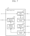
- FIG. 7 is a block diagram illustrating a configuration of the ARQ control unit 10.
- the ARQ control unit 10 includes a transmission buffer 101, a transmission data output unit 102, a reception buffer 103, a received frame output unit 104, a sequence missing determining unit 105, and a retransmission request output unit 106.
- the transmission buffer 101 is an internal buffer that stores transmission frames (1a) input from the outside in order of sequence numbers.
- the transmission data output unit 102 outputs the transmission frame (1a) read from the transmission buffer 101 in the order of sequence numbers to the optical transceiver 2 as transmission data (1).
- the reception buffer 103 is an internal buffer that stores the received data (2) output from the optical transceiver 2 as a received frame (2a) in the order of sequence numbers.
- the received frame output unit 104 outputs the received frames (2a) stored in the reception buffer 103 to the outside of the device in the order of sequence numbers.
- the sequence missing determining unit 105 is a determination unit that determines whether or not missing has occurred in the sequence number of the received frame (2a) stored in the reception buffer 103.
- the retransmission request output unit 106 outputs a retransmission request signal (10) of the received frame (2a) corresponding to the missing sequence number to the low-speed transmitter 12.
- a specific operation of the optical space communications transmission and reception terminal 1B is as follows.
- the ARQ control unit 10 outputs the transmission frame (1a) input from the outside of the device to the optical transceiver 2 as transmission data (1).
- the optical transceiver 2 modulates the transmission data (1) input from the ARQ control unit 10 at a symbol rate synchronized with the transmission clock signal (5) supplied from the transmission clock source 3, and outputs the modulated transmission optical signal (3) to the intensity modulation unit 4.
- the low-speed transmitter 12 outputs a signal modulated at a symbol rate synchronized with the transmission clock signal (5) to the intensity modulation unit 4.
- the low-speed transmitter 12 outputs, to the intensity modulation unit 4, a signal obtained by modulating the retransmission request signal (10) at a symbol rate synchronized with the transmission clock signal (5).
- the intensity modulation unit 4 superimposes the signal output from the low-speed transmitter 12 on the transmission optical signal (3) to generate an intensity-modulated transmission optical signal (6), and outputs the intensity-modulated transmission optical signal (6) to the fiber coupling unit 5.
- the intensity-modulated signal (8a) occurs due to intensity fluctuation of the optical signal generated when the optical transceiver 2 modulates the optical signal. Therefore, by setting the frequency of the intensity-modulated signal (8a) superimposed on the transmission optical signal (3) to, for example, a frequency equal to or less than 1/10 times the symbol rate, the BPF 83 or 88 illustrated in FIGS. 4 and 5 can suppress crosstalk to the intensity-modulated signal (8a).
- the fiber coupling unit 5 collimates the transmission optical signal (6) intensity-modulated by the intensity modulation unit 4 and outputs the collimated light of the transmission optical signal (6) to the beam splitter 7.
- the beam splitter 7 outputs collimated light of the transmission optical signal (6) output from the fiber coupling unit 5 to the tracking mirror 6, and distributes a part of the transmission optical signal (6) to the angle sensor 8A.
- the angle sensor 8A detects a propagation angle error (7) of the optical signal distributed by the beam splitter 7, and outputs the detected propagation angle error (7) to the tracking mirror 6.
- the tracking mirror 6 corrects the propagation angle of the transmission optical signal (6) collimated by the fiber coupling unit 5 on the basis of the propagation angle error (7) detected by the angle sensor 8A. An optical signal whose propagation angle has been corrected is output to space. As a result, the propagation direction of the optical signal transmitted to the paired optical space communications transmission and reception terminal 1B is compensated.
- the tracking mirror 6 When the optical signal transmitted from the paired optical space communications transmission and reception terminal 1B and propagating in the space is incident on the tracking mirror 6, the tracking mirror 6 outputs the incident optical signal to the side of the fiber coupling unit 5 via the beam splitter 7.
- the beam splitter 7 outputs the optical signal output from the tracking mirror 6 to the fiber coupling unit 5, and distributes a part of the optical signal to the angle sensor 8A.
- the light output from the fiber coupling unit 5 to the tracking mirror 6 and the light output from the tracking mirror 6 to the fiber coupling unit 5 are arranged on the same optical axis.
- the fiber coupling unit 5 includes a wavelength filter that separates the input light for each wavelength.
- the fiber coupling unit 5 separates the light in the two directions using a wavelength filter and couples the light to the optical fiber.
- the fiber coupling unit 5 may be provided with an optical circulator that separates light in two directions.
- the light output from the fiber coupling unit 5 to the tracking mirror 6 and the light output from the tracking mirror 6 to the fiber coupling unit 5 are made parallel to each other.
- the angle sensor 8A detects a propagation angle error (7) of the light output from the tracking mirror 6 to the fiber coupling unit 5 among the light in two directions.
- the tracking mirror 6 may correct the propagation angles of both the light output from the fiber coupling unit 5 to the tracking mirror 6 and the light output from the tracking mirror 6 to the fiber coupling unit 5 using the propagation angle error (7) detected from the light output from the tracking mirror 6 to the fiber coupling unit 5.
- the fiber coupling unit 5 couples the optical signal output from the tracking mirror 6 to the optical fiber.
- the optical fiber amplifier 9 amplifies the intensity of the received optical signal (4) coupled to the optical fiber by the fiber coupling unit 5, and outputs the received optical signal (4) with the amplified intensity to the optical transceiver 2 through the optical fiber.
- the angle sensor 8A generates an intensity-modulated signal (8a) from a part of the optical signal distributed by the beam splitter 7, and outputs the intensity-modulated signal (8a) to the low-speed receiver 11.
- the low-speed receiver 11 demodulates and decodes the intensity-modulated signal (8a) output from the angle sensor 8A to reproduce a reception clock signal (8) synchronized with the symbol rate.
- the reception clock signal (8) reproduced by the low-speed receiver 11 is output to the optical transceiver 2.
- the optical transceiver 2 samples the received optical signal (4) propagated through the optical fiber at a cycle synchronized with the reception clock signal (8).
- the optical transceiver 2 demodulates and decodes the sampled signal to generate received data (2), and outputs the generated received data (2) to the ARQ control unit 10.
- the ARQ control unit 10 stores the received data (2) output from the optical transceiver 2 as a received frame (2a), and in a case where a sequence number is missing in the stored received frame (2a), outputs a retransmission request signal (10) of the received frame (2a) corresponding to the missing sequence number to the low-speed transmitter 12.
- the optical transceiver 2 coherently detects the received optical signal (4) (the transmission optical signal (6) transmitted from the paired optical space communications transmission and reception terminal 1B). As a result, the optical transceiver 2 can demodulate and decode a transmission optical signal having a wavelength different from that of the transmission clock signal from the received optical signal (4) (intensity-modulated transmission optical signal (6)).
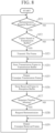
- FIG. 8 is a flowchart illustrating the operation of the ARQ control unit 10.
- the transmission data output unit 102 checks whether or not a retransmission request signal (9) is received from the low-speed receiver 11 (step ST1). When the retransmission request signal (9) is not received (step ST1; NO), the process proceeds to step ST4. Further, when the retransmission request signal of the communication frame corresponding to the specific sequence number is received (step ST1; YES), the transmission data output unit 102 checks whether or not the transmission frame (1a) is stored in the transmission buffer 101 (step ST2). When the transmission frame (1a) is not stored in the transmission buffer 101 (step ST2; NO), the process proceeds to step ST4.
- the transmission data output unit 102 outputs the transmission frame (1a) stored in the transmission buffer 101 to the optical transceiver 2 as transmission data (1) (step ST3).
- the transmission buffer 101 stores the transmission frames (1a) input from the outside in order of sequence numbers (step ST4). If there is an unoutput frame among the transmission frames stored in the transmission buffer 101, the transmission data output unit 102 outputs the frame to the optical transceiver 2 (step ST5).
- the reception buffer 103 stores the received data (2) output from the optical transceiver 2 as the received frame (2a) in the order of sequence numbers (step ST6).
- the sequence missing determining unit 105 determines whether or not the sequence number is missing in the received frame (2a) stored in the reception buffer 103 (step ST7).
- the retransmission request output unit 106 outputs the retransmission request signal (10) of the communication frame with the missing sequence number to the low-speed transmitter 12 (step ST8).
- step ST7 the received frame output unit 104 reads the unoutput received frame among the received frames stored in the reception buffer 103, and outputs the read received frame (2a) to the outside of the device (step ST9). Thereafter, the process returns to step ST1, and a series of processing from step ST1 is repeatedly performed.
- the missing of the sequence number occurs when the frame corresponding to the missing sequence number cannot be demodulated and decoded by the optical transceiver 2.
- the wavefront of light propagating in the space is distorted due to the influence of atmospheric fluctuations, and the intensity decreases (loss) when an optical signal in which the wavefront is distorted is coupled to the optical fiber.
- the SNR of the received optical signal (4) is lower than the SNR necessary for demodulation, so that the received frame cannot be demodulated and decoded.
- the ARQ control unit 10 interpolates missing of the sequence number of the received frame stored in the reception buffer 103, and then outputs the frames in order of sequence numbers. Note that the frames stored in the transmission buffer 101 and the reception buffer 103 are discarded when a predetermined time has elapsed.
- FIG. 9 is a block diagram illustrating a hardware configuration for implementing functions of the ARQ control unit 10.
- FIG. 10 is a block diagram illustrating a hardware configuration for executing software for implementing the functions of the ARQ control unit 10.
- the functions of the transmission buffer 101, the transmission data output unit 102, the reception buffer 103, the received frame output unit 104, the sequence missing determining unit 105, and the retransmission request output unit 106 included in the ARQ control unit 10 are implemented by a processing circuit. That is, the ARQ control unit 10 includes a processing circuit that executes the processing from step ST1 to step ST9 illustrated in FIG. 8 .
- the processing circuit may be dedicated hardware or a central processing unit (CPU) that executes a program stored in a memory.
- CPU central processing unit
- the processing circuit 200 corresponds to, for example, a single circuit, a composite circuit, a programmed processor, a parallel programmed processor, an application specific integrated circuit (ASIC), a field-programmable gate array (FPGA), or a combination thereof.
- the functions of the transmission buffer 101, the transmission data output unit 102, the reception buffer 103, the received frame output unit 104, the sequence missing determining unit 105, and the retransmission request output unit 106 included in the ARQ control unit 10 may be implemented by separate processing circuits, or these functions may be collectively implemented by one processing circuit.
- the functions of the transmission buffer 101, the transmission data output unit 102, the reception buffer 103, the received frame output unit 104, the sequence missing determining unit 105, and the retransmission request output unit 106 included in the ARQ control unit 10 are implemented by software, firmware, or a combination of software and firmware. Note that, software or firmware is written as a program and stored in a memory 202.
- the processor 201 reads and executes the program stored in the memory 202, thereby implementing the functions of the transmission buffer 101, the transmission data output unit 102, the reception buffer 103, the received frame output unit 104, the sequence missing determining unit 105, and the retransmission request output unit 106 included in the ARQ control unit 10.
- the ARQ control unit 10 includes the memory 202 for storing a program that results in execution of the processing of steps ST1 to ST9 in the flowchart illustrated in FIG. 8 when executed by the processor 201.
- the memory 202 may be a computer-readable storage medium storing a program for causing a computer to function as the transmission buffer 101, the transmission data output unit 102, the reception buffer 103, the received frame output unit 104, the sequence missing determining unit 105, and the retransmission request output unit 106.
- the memory 202 corresponds to, for example, a nonvolatile or volatile semiconductor memory such as a random access memory (RAM), a read only memory (ROM), a flash memory, an erasable programmable read only memory (EPROM), or an electrically-EPROM (EEPROM: a magnetic disk, a flexible disk, an optical disk, a compact disk, a mini disk, or a DVD.
- RAM random access memory
- ROM read only memory
- EPROM erasable programmable read only memory
- EEPROM electrically-EPROM
- a part of the functions of the transmission buffer 101, the transmission data output unit 102, the reception buffer 103, the received frame output unit 104, the sequence missing determining unit 105, and the retransmission request output unit 106 included in the ARQ control unit 10 may be implemented by dedicated hardware, and the remaining part may be implemented by software or firmware.
- the functions of the transmission buffer 101 and the reception buffer 103 are implemented by the processing circuit 200 that is dedicated hardware, and the functions of the transmission data output unit 102, the received frame output unit 104, the sequence missing determining unit 105, and the retransmission request output unit 106 are implemented by the processor 201 reading and executing a program stored in the memory 202.
- the processing circuit can implement the above functions by hardware, software, firmware, or a combination thereof.
- the angle sensor 8A extracts the intensity-modulated signal from the optical signal before being coupled to the optical fiber.
- the low-speed receiver 11 demodulates and decodes the intensity-modulated signal output from the angle sensor 8A to reproduce a clock signal synchronized with the symbol rate, and outputs the reproduced clock signal to the optical transceiver 2 as a reception clock signal (8). Even in a case where communication is disabled due to a decrease in the SNR of the received optical signal caused by a loss generated when the optical signal is coupled to the optical fiber, the angle sensor 8A can stably extract the intensity-modulated signal.
- the low-speed receiver 11 can stably demodulate and decode the retransmission request signal as compared with the optical transceiver 2, and can stably supply the reception clock signal to the optical transceiver 2.
- the optical space communications transmission and reception terminal 1B can shorten the time until the communication is recovered, and can prevent a decrease in the communication capacity.
- the low-speed receiver 11 can stably demodulate and decode the retransmission request signal of the communication frame and output the signal to the ARQ control unit 10. As a result, it is possible to respond to the retransmission request without delay and suppress the transmission delay.
- the ARQ control unit 10 includes the transmission buffer 101, the transmission data output unit 102, the reception buffer 103, the received frame output unit 104, the sequence missing determining unit 105, and the retransmission request output unit 106. With these components, even if the sequence number of the frame stored in the reception buffer 103 is missing, the ARQ control unit 10 can request retransmission of the corresponding frame without delay.
- the optical space communications system 1 includes a pair of optical space communications transmission and reception terminals 1B having the same configuration, and bidirectional communication is performed between the pair of optical space communications transmission and reception terminals 1B having the same configuration.
- FIG. 11 is a block diagram illustrating a configuration of an optical transceiver 2A according to a third embodiment included in an optical space communications transmission and reception terminal 1A or 1B.
- the optical transceiver 2A is provided instead of the optical transceiver 2 in the optical space communications transmission and reception terminal 1A illustrated in FIG. 1 or the optical space communications transmission and reception terminal 1B illustrated in FIG. 6 .
- the optical transceiver 2A includes a transmission unit 21, an optical modulator 22, a Doppler shift estimator 23, a receiving unit 24, and a coherent detector 25.
- the transmission unit 21 outputs a signal obtained by modulating the transmission data (1) at a symbol rate synchronized with the transmission clock signal (5).
- the transmission unit 21 includes a modulated signal conversion unit 211.
- the transmission unit 21 is, for example, a digital signal processor (DSP).
- DSP digital signal processor
- the modulated signal conversion unit 211 converts the input transmission data (1) into a signal modulated at a symbol rate synchronized with the transmission clock signal (5).
- the optical modulator 22 converts the modulated signal output from the transmission unit 21 into a transmission optical signal (3) and outputs the transmission optical signal (3) to the intensity modulation unit 4.
- the Doppler shift estimator 23 estimates the Doppler shift amount of the reception clock signal (8) input from the angle sensor 8 or the low-speed receiver 11.
- the Doppler shift amount is a value obtained by dividing the frequency difference generated by the Doppler shift by the frequency before the shift.
- the Doppler shift estimator 23 detects a frequency difference between the reception clock signal (8) and an internal clock signal having the same nominal frequency as the reception clock signal (8), and divides the frequency difference by the nominal frequency to calculate the Doppler shift amount.
- the reception clock signal (8) is also input to the receiving unit 24.
- the coherent detector 25 coherently detects the received optical signal (4) output from the optical fiber amplifier 9.
- the receiving unit 24 decodes the received data (2) using the coherently detected received optical signal (4), the estimated value of the Doppler shift amount in the reception clock signal (8), and the reception clock signal (8).
- the receiving unit 24 is, for example, a DSP.
- the receiving unit 24 includes a sampling unit 241, an adaptive equalization unit 242, an SNR estimating unit 243, a frequency difference estimating unit 244, a frequency difference compensating unit 245, a phase difference estimating unit 246, a phase difference compensating unit 247, and a decoding unit 248.
- the sampling unit 241 samples the coherently detected received optical signal (4) at a symbol rate synchronized with the reception clock signal (8).
- the sampling unit 241 samples the coherently detected signal at a symbol rate synchronized with the reception clock signal (8) or a rational multiple of the symbol rate.
- the adaptive equalization unit 242 adaptively equalizes the signal sampled by the sampling unit 241.
- the adaptive equalization unit 242 performs equalization so that an error between an output signal point and an ideal signal point is minimized on average within a certain period of time.
- the modulation system is QuadraPhase-Shift Keying (QPSK)
- QPSK QuadraPhase-Shift Keying
- adaptive equalization can be achieved by a constant envelope algorithm.
- the SNR estimating unit 243 estimates an SNR of the adaptively-equalized signal. For example, the SNR estimating unit 243 estimates an error amount by averaging errors from ideal signal points of the equalized signal within a certain period of time to estimate an SNR.
- the frequency difference estimating unit 244 estimates the frequency difference in the adaptively-equalized signal using the signal adaptively equalized by the adaptive equalization unit 242, the estimated value of the SNR, and the Doppler shift amount estimated value. For example, in the frequency difference estimation processing, a plurality of samples are used to suppress the influence of noise, and sequential calculation using the plurality of samples is performed to average the estimated values. In a case where the frequency difference due to the Doppler shift changes while the SNR decreases due to the influence of atmospheric fluctuations of the optical signal, it takes time until the initial value of sequential calculation in the estimation of the frequency difference deviates from the true value and converges. In this case, the frequency difference cannot be compensated, and it takes time to recover the communication even if the SNR of the received optical signal is recovered.
- the optical transceiver 2A is hardly affected by the distortion of the wavefront due to the influence of atmospheric fluctuations, and the receiving unit 24 can stably calculate the change in the frequency difference due to the Doppler shift by estimating the Doppler shift amount from the stably supplied reception clock signal (8).
- the frequency difference is estimated from a signal obtained by adaptively equalizing the reception clock signal (8) since the wavelength of the light source itself changes due to the influence of temperature, for example, in addition to the Doppler shift.
- the frequency difference is estimated from the signal obtained by adaptively equalizing the reception clock signal (8) with the frequency difference calculated using the estimated value of the Doppler shift amount as an initial value, so that the convergence of the estimated value is accelerated and the time until the communication is recovered is shortened.
- the frequency difference estimating unit 244 estimates the frequency difference of the adaptively-equalized signal. In a case where the estimated value of the SNR becomes equal to or larger than the threshold again after falling below the threshold, the frequency difference estimating unit 244 estimates the frequency difference of the adaptively-equalized signal using the estimated value of the frequency difference immediately before the estimated value of the SNR falls below the threshold and the estimated value of the frequency difference calculated on the basis of the transition of the estimated value of the Doppler shift amount after the estimated value of the SNR falls below the threshold as initial values.
- the initial value of the estimated value of the frequency difference is obtained by f0 + fc (d1 - d0).
- fc is the frequency of the transmission optical signal.
- the frequency difference compensating unit 245 compensates for the frequency difference of the adaptively-equalized signal on the basis of the frequency difference estimated by the frequency difference estimating unit 244.
- the phase difference estimating unit 246 estimates a phase difference in the signal whose frequency difference has been compensated by the frequency difference compensating unit 245.
- the phase difference compensating unit 247 compensates for the phase difference of the adaptively-equalized signal on the basis of the phase difference estimated by the phase difference estimating unit 246.
- the phase difference can be estimated and compensated by the method described in Reference Literature 1, for example, by using the Viterbi algorithm.
- the frequency difference estimating unit 244 can estimate the frequency difference of the adaptively-equalized signal by the method described in Reference Literature 2, and can also remove the phase modulation component by raising the QPSK signal to the fourth power.
- the decoding unit 248 decodes the signal in which the phase difference is compensated.
- FIG. 12 is a flowchart illustrating operations of the transmission unit 21 and the receiving unit 24.
- the modulated signal conversion unit 211 converts the transmission data (1) input from the outside of the device or the ARQ control unit 10 into a signal modulated at a symbol rate synchronized with the transmission clock signal (5) (step ST1a).
- the modulated signal output from the transmission unit 21 is converted into a transmission optical signal (3) by the optical modulator 22 and output to the intensity modulation unit 4.
- the received optical signal (4) received by the paired optical space communications transmission and reception terminal 1A or 1B is coherently detected by the coherent detector 25.
- the sampling unit 241 samples the coherently detected received optical signal (4) at a symbol rate synchronized with the reception clock signal (8).
- the adaptive equalization unit 242 adaptively equalizes the signal sampled by the sampling unit 241 (step ST2a).
- the SNR estimating unit 243 estimates the SNR of the signal adaptively equalized by the adaptive equalization unit 242 (step ST3a). Subsequently, the frequency difference estimating unit 244 estimates the frequency difference in the adaptively-equalized signal using the signal adaptively equalized by the adaptive equalization unit 242, the estimated value of the SNR, and the Doppler shift amount estimated value (step ST4a). The frequency difference compensating unit 245 compensates for the frequency difference of the adaptively-equalized signal on the basis of the frequency difference estimated by the frequency difference estimating unit 244 (step ST5a).
- the phase difference estimating unit 246 estimates a phase difference in the signal whose frequency difference has been compensated by the frequency difference compensating unit 245 (step ST6a).
- the phase difference compensating unit 247 compensates for the phase difference of the adaptively-equalized signal on the basis of the phase difference estimated by the phase difference estimating unit 246 (step ST7a).
- the decoding unit 248 decodes the signal in which the phase difference has been compensated, and outputs the decoded data to the outside of the device or the ARQ control unit 10 as received data (2) (step ST8a).
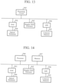
- FIG. 13 is a block diagram illustrating a hardware configuration for implementing the functions of the transmission unit 21 and the receiving unit 24.
- FIG. 14 is a block diagram illustrating a hardware configuration for executing software for implementing the functions of the transmission unit 21 and the receiving unit 24.
- an optical modulator 300 is the optical modulator 22 illustrated in FIG. 11 .
- the optical modulator 300 is connected to a processing circuit 305, a processor 306, and a memory 307 via a DA converter (DAC) 301.
- the DAC 301 converts a signal input to the optical modulator 300 from a digital signal to an analog signal.
- a Doppler shift estimator 302 is the Doppler shift estimator 23 illustrated in FIG. 11 .
- a coherent detector 303 is the coherent detector 25 illustrated in FIG. 11 .
- the coherent detector 303 is connected to the processing circuit 305, the processor 306, and the memory 307 via an AD converter (ADC) 304.
- the ADC 304 converts the signal output from the coherent detector 303 from an analog signal to a digital signal.
- the optical transceiver 2A includes a processing circuit that executes processing from step STla to step ST8a illustrated in FIG. 12 .
- the processing circuit may be dedicated hardware, or may be a CPU that executes a program stored in the memory.
- the processing circuit is the processing circuit 305 of dedicated hardware illustrated in FIG. 13
- the processing circuit 305 corresponds to, for example, a single circuit, a composite circuit, a programmed processor, a parallel programmed processor, ASIC, FPGA, or a combination thereof.
- the functions of the transmission unit 21 and the receiving unit 24 included in the optical transceiver 2A may be implemented by separate processing circuits, or these functions may be collectively implemented by one processing circuit.
- the processing circuit is the processor 306 illustrated in FIG. 14
- the functions of the transmission unit 21 and the receiving unit 24 included in the optical transceiver 2A are implemented by software, firmware, or a combination of software and firmware. Note that the software or firmware is described as a program and stored in the memory 307.
- the processor 306 reads and executes the program stored in the memory 307 to implement the functions of the transmission unit 21 and the receiving unit 24 included in the optical transceiver 2A.
- the optical transceiver 2A includes the memory 307 for storing a program by which the processing from step STla to step ST8a in the flowchart illustrated in FIG. 12 is executed as a result.
- These programs cause a computer to execute the procedures or methods performed by the transmission unit 21 and the receiving unit 24.
- the memory 307 may be a computer-readable storage medium storing a program for causing a computer to function as the transmission unit 21 and the receiving unit 24.
- the memory 307 corresponds to, for example, a nonvolatile or volatile semiconductor memory such as RAM, ROM, a flash memory, EPROM, or EEPROM: a magnetic disk, a flexible disk, an optical disk, a compact disk, a mini disk, or DVD.
- a nonvolatile or volatile semiconductor memory such as RAM, ROM, a flash memory, EPROM, or EEPROM: a magnetic disk, a flexible disk, an optical disk, a compact disk, a mini disk, or DVD.
- a part of the functions of the transmission unit 21 and the receiving unit 24 included in the optical transceiver 2A may be implemented by dedicated hardware, and the remaining part may be implemented by software or firmware.
- the function of the transmission unit 21 is implemented by the processing circuit 305 that is dedicated hardware, and the function of the receiving unit 24 is implemented by the processor 306 reading and executing a program stored in the memory 307.
- the processing circuit can implement the above functions by hardware, software, firmware, or a combination thereof.
- the receiving unit 24 samples the coherently detected received optical signal at the symbol rate synchronized with the reception clock signal, adaptively equalizes the sampled signal, estimates the SNR in the adaptively-equalized signal, estimates the frequency difference in the adaptively-equalized signal using the adaptively-equalized signal, the estimated value of the SNR, and the estimated value of the Doppler shift amount, compensates the frequency difference of the adaptively-equalized signal on the basis of the estimated frequency difference, estimates the phase difference in the signal in which the frequency difference is compensated, compensates the phase difference of the adaptively-equalized signal on the basis of the estimated phase difference, and outputs data obtained by decoding the signal in which the phase difference is compensated as received data.
- the optical space communications transmission and reception terminal 1A or 1B includes the optical transceiver 2A
- the effects described in the first or second embodiment can be obtained. Furthermore, as described above, since the time for estimating the frequency difference of the reception clock signal (8) is shortened, the time until the communication is recovered when the SNR of the received optical signal is recovered is shortened.
- the frequency difference estimating unit 244 estimates the frequency difference in the adaptively-equalized signal in a case where the SNR is equal to or larger than the threshold, and estimates the frequency difference in the adaptively-equalized signal using, as initial values, the estimated value of the frequency difference immediately before the SNR falls below the threshold and the estimated value of the frequency difference calculated on the basis of the transition of the estimated value of the Doppler shift amount after the SNR falls below the threshold when the SNR falls below the threshold and then becomes equal to or larger than the threshold again.
- the time for estimating the frequency difference of the reception clock signal (8) is shortened, the time until the communication is recovered when the SNR of the received optical signal is recovered is shortened.
- optical space communications transmission and reception terminal can be used for a feeder link in a satellite communication network, for example.
Landscapes
- Physics & Mathematics (AREA)
- Electromagnetism (AREA)
- Engineering & Computer Science (AREA)
- Computer Networks & Wireless Communication (AREA)
- Signal Processing (AREA)
- Astronomy & Astrophysics (AREA)
- General Physics & Mathematics (AREA)
- Optical Communication System (AREA)
Abstract
Description
- The present disclosure relates to an optical space communications transmission and reception terminal and an optical space communications system.
- Since optical space communications have characteristics that downsizing of a transceiver can be expected and low power consumption can be expected, application to a feeder link in a next-generation satellite communication network has been studied (See, for example, Non-Patent
Literature 1.). An optical fiber amplifier is used for a transceiver in optical space communications in order to improve reception sensitivity. The optical fiber amplifier is an amplifier that amplifies an optical signal coupled to the optical fiber. The optical signal amplified by the optical fiber amplifier is output to the optical transceiver. The optical transceiver extracts a clock signal corresponding to a symbol rate from the optical signal amplified by the optical fiber amplifier, and samples a received optical signal in synchronization with the extracted clock signal, thereby performing demodulation processing of the received optical signal. - Non-Patent Literature 1: H. Hauschildt et al., "HydRON: High thRoughput Optical Network" 2019 IEEE International Conference on Space Optical Systems and Applications (ICSOS), Portland, OR, USA, 2019.
- In order to use an optical fiber amplifier, it is necessary to condense an optical signal propagated in the atmosphere to be coupled to the optical fiber. However, since the wavefront of the optical signal propagated in the atmosphere is distorted due to the influence of atmospheric fluctuations, loss occurs when the optical signal is coupled to the optical fiber. As a result, a signal noise ratio (SNR) of the received optical signal amplified by the optical fiber amplifier decreases. Furthermore, since the loss of the optical signal generated at the time of coupling to the optical fiber fluctuates with atmospheric fluctuations, the SNR of the received optical signal also fluctuates with time.
- When the SNR of the received optical signal fluctuates with time and falls below the SNR necessary for extracting the clock signal, the optical transceiver cannot extract the clock signal from the received optical signal, and the communication is disabled. In this case, the conventional optical space communications system has a problem that communication cannot be recovered until a clock signal is extracted from the received optical signal amplified by the optical fiber amplifier after the SNR of the received optical signal is recovered. Note that the communication capacity of the optical space communications decreases as it takes time to recover the communications.
- The present disclosure solves the above problem, and an object of the present disclosure is to provide an optical space communications transmission and reception terminal and an optical space communications system capable of extracting a clock signal without waiting for recovery of an SNR of a received optical signal when communication is disabled due to a decrease in the SNR of the received optical signal caused by a loss generated when the optical signal is coupled to an optical fiber.
- An optical space communications transmission and reception terminal according to the present disclosure is an optical space communications transmission and reception terminal that performs bidirectional communication with a paired optical space communications transmission and reception terminal having a same configuration, and the optical space communications transmission and reception terminal includes: an optical transceiver to convert transmission data into a transmission optical signal modulated at a symbol rate synchronized with a transmission clock signal and output the transmission optical signal, and generate received data by demodulating and decoding a signal obtained by sampling a received optical signal at a cycle synchronized with a reception clock signal; an intensity modulation unit to generate a transmission optical signal obtained by superimposing a transmission clock signal on the transmission optical signal output from the optical transceiver and performing intensity modulation, and output the generated transmission optical signal; a transmission clock source to supply a common transmission clock signal to the optical transceiver and the intensity modulation unit; a fiber coupling unit to output an intensity-modulated transmission optical signal as collimated light and couple the input optical signal to an optical fiber; an optical fiber amplifier to amplify an optical signal coupled to the optical fiber by the fiber coupling unit and output the amplified optical signal to the optical transceiver as a received optical signal; a tracking mirror to output an optical signal propagated in space to a side of the fiber coupling unit, output the transmission optical signal collimated by the fiber coupling unit to the space, and output, when a propagation angle error is input, an optical signal in which a propagation angle is corrected on a basis of the input propagation angle error; a beam splitter to divide a part of an optical signal propagating between the tracking mirror and the fiber coupling unit; and an angle sensor to output a propagation angle error detected from the optical signal divided by the beam splitter to the tracking mirror, and output a clock signal extracted from the optical signal divided by the beam splitter to the optical transceiver as a reception clock signal.
- According to the present disclosure, an angle sensor extracts a clock signal from an optical signal before being coupled to an optical fiber. As a result, the optical space communications transmission and reception terminal according to the present disclosure can extract the clock signal without waiting for recovery of the SNR of the received optical signal when communication is disabled due to a decrease in the SNR of the received optical signal caused by a loss generated when the optical signal is coupled to the optical fiber. As a result, the time until the communication is recovered can be shortened as compared with a case where the clock signal is extracted after the recovery of the SNR of the received optical signal.
-
-
FIG. 1 is a block diagram illustrating a configuration of an optical space communications system according to a first embodiment. -
FIG. 2 is a block diagram illustrating a configuration of an optical space communications transmission and reception terminal according to the first embodiment. -
FIG. 3 is a block diagram illustrating a configuration example of an intensity modulation unit. -
FIG. 4 is a block diagram illustrating a configuration of an example (1) of an angle sensor. -
FIG. 5 is a block diagram illustrating a configuration of an example (2) of the angle sensor. -
FIG. 6 is a block diagram illustrating a configuration of an optical space communications transmission and reception terminal according to a second embodiment. -
FIG. 7 is a block diagram illustrating a configuration of an ARQ control unit. -
FIG. 8 is a flowchart illustrating an operation of the ARQ control unit. -
FIG. 9 is a block diagram illustrating a hardware configuration for implementing a function of the ARQ control unit. -
FIG. 10 is a block diagram illustrating a hardware configuration for executing software for implementing the function of the ARQ control unit. -
FIG. 11 is a block diagram illustrating a configuration of an optical transceiver included in an optical space communications transmission and reception terminal according to a third embodiment. -
FIG. 12 is a flowchart illustrating operations of a transmission unit and a receiving unit included in an optical transceiver in the third embodiment. -
FIG. 13 is a block diagram illustrating a hardware configuration for implementing functions of the transmission unit and the receiving unit included in the optical transceiver in the third embodiment. -
FIG. 14 is a block diagram illustrating a hardware configuration for executing software for implementing the functions of the transmission unit and the receiving unit included in the optical transceiver in the third embodiment. -
FIG. 1 is a block diagram illustrating a configuration of an opticalspace communications system 1 according to a first embodiment. InFIG. 1 , the opticalspace communications system 1 is a system that performs communication using light propagating in space, and includes a pair of optical space communications transmission andreception terminals 1A. In the opticalspace communications system 1, as illustrated inFIG. 1 , the optical space communications transmission andreception terminal 1A performs bidirectional communication with a paired optical space communications transmission andreception terminal 1A having the same configuration. -
FIG. 2 is a block diagram illustrating a configuration of the optical space communications transmission andreception terminal 1A. The optical space communications transmission andreception terminal 1A includes anoptical transceiver 2, atransmission clock source 3, anintensity modulation unit 4, afiber coupling unit 5, atracking mirror 6, abeam splitter 7, anangle sensor 8, and anoptical fiber amplifier 9. Theoptical transceiver 2, theintensity modulation unit 4, thefiber coupling unit 5, and theoptical fiber amplifier 9 are connected to each other by an optical fiber. Further, theoptical transceiver 2, thetransmission clock source 3, thetracking mirror 6, and theangle sensor 8 are connected to each other by signal lines. - The
optical transceiver 2 converts transmission data (1) into a transmission optical signal (3) modulated at a symbol rate synchronized with a transmission clock signal (5) and outputs the transmission optical signal (3). In addition, theoptical transceiver 2 samples a received optical signal (4) at a cycle synchronized with a reception clock signal (8), and generates received data (2) by demodulating and decoding the sampled signal. - The
transmission clock source 3 supplies a common transmission clock signal (5) to theoptical transceiver 2 and theintensity modulation unit 4. When thetransmission clock source 3 outputs the transmission clock signal (5) having a frequency of 100 MHz, theoptical transceiver 2 multiplies the frequency of the transmission clock signal (5) by, for example, 20 to generate a transmission optical signal (3) modulated at a symbol rate of 2 GHz. - The
intensity modulation unit 4 superimposes the transmission clock signal (5) on the transmission optical signal (3) output from theoptical transceiver 2 to generate an intensity-modulated transmission optical signal (3), and outputs an intensity-modulated transmission optical signal (6) to thefiber coupling unit 5. For example, theintensity modulation unit 4 is an intensity modulator that superimposes the transmission clock signal (5) as a modulation signal on the transmission optical signal (3). In intensity modulation processing of the transmission optical signal, theintensity modulation unit 4 prevents the modulation amplitude from being small and the intensity of the transmission optical signal (3) from greatly fluctuating. As a result, it is possible to reduce the influence of the fluctuation in the intensity of the intensity-modulated transmission optical signal (3) on the modulation and demodulation processing of the optical signal performed by theoptical transceiver 2. - The
intensity modulation unit 4 has, for example, a configuration illustrated inFIG. 3. FIG. 3 is a block diagram illustrating a configuration example of theintensity modulation unit 4. Theintensity modulation unit 4 includes an electro-optical converter 41 and anoptical multiplexer 42. The electro-optical converter 41 is "E/O" inFIG. 3 . The electro-optical converter 41 converts the transmission clock signal (5) supplied from thetransmission clock source 3 from an electrical signal into an optical signal. - The
optical multiplexer 42 multiplexes the transmission optical signal (3) output from theoptical transceiver 2 and the transmission clock signal converted into the optical signal by the electro-optical converter 41. As a result, the transmission clock signal (5) is superimposed on the transmission optical signal (3), and the intensity of the transmission optical signal (3) is modulated. Note that, the transmission clock signal (5) converted into the optical signal is an optical signal having a wavelength different from that of the transmission optical signal (3). That is, the transmission optical signal (6) intensity-modulated by theoptical multiplexer 42 is a signal in which signals having different wavelengths are wavelength-multiplexed. The transmission optical signal (6) is output from theoptical multiplexer 42 to thefiber coupling unit 5. - The
fiber coupling unit 5 outputs the transmission optical signal (6) intensity-modulated by theintensity modulation unit 4 as collimated light (parallel light), and couples the optical signal input from thetracking mirror 6 side to the optical fiber. For example, thefiber coupling unit 5 includes a condensing lens that condenses the optical signal from thetracking mirror 6, and an optical system holder that holds the condensing lens and the optical fiber. The optical fiber held by the optical system holder is connected to the input side of theoptical fiber amplifier 9. The optical signal from thetracking mirror 6 is condensed by the condensing lens and is incident on the optical fiber. - When an optical signal transmitted from the paired optical space communications transmission and
reception terminal 1A having the same configuration and propagating in the space is incident on thetracking mirror 6, thetracking mirror 6 outputs the incident optical signal toward thefiber coupling unit 5. For example, thetracking mirror 6 includes at least a mirror unit that reflects incident light toward thefiber coupling unit 5 and a mirror drive unit that changes an angle of the mirror unit. - When a propagation angle error (7) of the optical signal is input from the
angle sensor 8, thetracking mirror 6 outputs an optical signal in which the propagation angle is corrected on the basis of the input propagation angle error (7). The propagation angle error (7) is a difference in propagation angle from the light beam coinciding with the optical axis. For example, the mirror drive unit changes the angle of the mirror unit so as to eliminate the propagation angle error (7), thereby correcting the propagation angle of the optical signal incident on thetracking mirror 6. The optical signal whose propagation angle has been corrected is output to the side of thefiber coupling unit 5 via thebeam splitter 7. - When the transmission optical signal made into collimated light by the
fiber coupling unit 5 is incident on thetracking mirror 6 via thebeam splitter 7, thetracking mirror 6 outputs the incident collimated light to space. As a result, the transmission optical signal is transmitted to the paired optical space communications transmission andreception terminal 1A. In addition, thetracking mirror 6 corrects the propagation angle of the transmission optical signal (6) collimated by thefiber coupling unit 5 on the basis of the propagation angle error (7) detected by theangle sensor 8, and outputs the optical signal with the corrected propagation angle to space. As a result, the propagation direction of the optical signal transmitted to the paired optical space communications transmission andreception terminal 1A is compensated. - The
beam splitter 7 distributes a part of the optical signal propagating between thefiber coupling unit 5 and thetracking mirror 6 to theangle sensor 8. For example, thebeam splitter 7 distributes a part of the transmission optical signal output from thefiber coupling unit 5 to thetracking mirror 6 to theangle sensor 8, and distributes a part of the transmission optical signal output from thetracking mirror 6 to thefiber coupling unit 5 to theangle sensor 8. - The
angle sensor 8 detects a propagation angle error (7) of the optical signal distributed by thebeam splitter 7, and outputs the detected propagation angle error (7) to thetracking mirror 6. Further, theangle sensor 8 extracts a clock signal from the optical signal distributed by thebeam splitter 7, and outputs the extracted clock signal to theoptical transceiver 2 as a reception clock signal (8). The reception clock signal (8) is a sine wave signal of a clock frequency or a signal configured by repetition of a 0 (low) value and a 1 (high) value, and only the frequency is used as a clock. - The
angle sensor 8 has, for example, a configuration illustrated inFIG. 4. FIG. 4 is a block diagram illustrating a configuration of an example (1) of theangle sensor 8. InFIG. 4 , theangle sensor 8 includes alens 81, a four-divided light receiving element 82 (Hereinafter, it is referred to as a four-dividedPD 82.), and a bandpass filter 83 (Hereinafter, it is referred to as aBPF 83.). - The
lens 81 condenses the optical signal distributed by thebeam splitter 7 at the center of the light receiving surface of the four-dividedPD 82. The four-dividedPD 82 is a split type light receiving element having a light receiving surface divided into four light receiving areas. TheBPF 83 is a bandpass filter having a frequency band of the transmission clock signal (5) in the paired optical space communications transmission andreception terminal 1A as a pass band. - The center of the light receiving surface of the four-divided
PD 82 is a position adjacent to all of the four light receiving areas. The four-dividedPD 82 includes, for example, a calculation unit to calculate a propagation angle error (7) of the optical signal condensed on the light receiving surface on the basis of the intensity of the light received in the four light receiving areas. When the condensing position of the optical signal deviates from the center of the light receiving surface, there is a difference in intensity of received light between the light receiving areas. The calculation unit of the four-dividedPD 82 calculates the deviation of the condensing position from the center of the light receiving surface on the basis of the difference in the intensity of the light received at each of the four light receiving areas and the total intensity of the light received at the four light receiving areas. Further, the calculation unit detects a propagation angle error (7) of the optical signal condensed on the light receiving surface on the basis of the deviation of the condensing position from the center of the light receiving surface. - In the optical
space communications system 1, an optical signal transmitted from the optical space communications transmission andreception terminal 1A on the transmission side to the optical space communications transmission andreception terminal 1A on the reception side is an optical signal whose intensity fluctuates in synchronization with the transmission clock signal (5). That is, the fluctuation in the total intensity of the light received at the four light receiving areas on the light receiving surface of the four-dividedPD 82 corresponds to the fluctuation in the intensity of the optical signal transmitted from the optical space communications transmission andreception terminal 1A on the transmission side. - The
BPF 83 can extract the clock signal by passing the frequency band of the transmission clock signal (5) in the optical space communications transmission andreception terminal 1A on the transmission side in a frequency band of the intensity fluctuation output from the four-dividedPD 82. The clock signal extracted by theBPF 83 is output to theoptical transceiver 2 as the reception clock signal (8). -
FIG. 5 is a block diagram illustrating a configuration of an example (2) of theangle sensor 8. InFIG. 5 , theangle sensor 8 includes abeam splitter 84, alens 85, a four-divided light receiving element 86 (Hereinafter, it is referred to as a four-dividedPD 86.), a photoelectric converter 87, and a bandpass filter 88 (Hereinafter, it is referred to as aBPF 88.). The photoelectric converter 87 is an "O/E" inFIG. 5 . Thebeam splitter 84 distributes the optical signal divided by thebeam splitter 7 into a four-dividedPD 86 and a photoelectric converter 87. Thelens 85 condenses the optical signal divided by thebeam splitter 7 at the center of the light receiving surface of the four-dividedPD 86. - Similarly to the four-divided
PD 82, the four-dividedPD 86 is a light receiving element having a light receiving surface divided into four light receiving areas. The center of the light receiving surface is a position adjacent to all of the four light receiving areas. The four-dividedPD 86 includes a calculation unit that calculates a propagation angle error (7) of the optical signal condensed on the light receiving surface on the basis of the intensity of the light received in the four light receiving areas. - When the condensing position of the optical signal deviates from the center of the light receiving surface, there is a difference in intensity of received light between the light receiving areas. The calculation unit of the four-divided
PD 86 calculates the deviation of the condensing position from the center of the light receiving surface on the basis of the difference in the intensity of the light received by each of the four light receiving areas and the total intensity of the light received by the four light receiving areas. Further, the calculation unit detects a propagation angle error (7) of the optical signal condensed on the light receiving surface on the basis of the deviation of the condensing position from the center of the light receiving surface. - The photoelectric converter 87 converts the optical signal divided by the
beam splitter 7 into an electrical signal. TheBPF 88 is a bandpass filter having a frequency band of the transmission clock signal (5) in the paired optical space communications transmission andreception terminal 1A as a pass band. - For example, a single mode fiber is used for the optical space communications transmission and
reception terminal 1A. The single mode fiber is generally an optical fiber having a low influence of mode dispersion, and has a restricted core diameter. On the other hand, the four-dividedPD 82, the four-dividedPD 86, and the photoelectric converter 87 illustrated inFIGS. 4 and 5 have a light receiving area larger than the core diameter of the optical fiber without restriction on the light receiving surface. As a result, even if the wavefront of the input light is distorted, theangle sensor 8 suppresses a decrease in the intensity of the detected optical signal as compared with the intensity of the optical signal when coupled to the optical fiber. That is, since theangle sensor 8 can detect the intensity fluctuation from the optical signal before being coupled to the optical fiber, even in a case where the wavefront of the light is distorted due to the influence of atmospheric fluctuations, the clock signal can be stably extracted from the received optical signal, and can be continuously supplied to theoptical transceiver 2. - The clock signal extracted from the received optical signal by the
angle sensor 8 is a clock signal synchronized with the symbol rate of the transmission optical signal from the paired optical space communications transmission andreception terminal 1A having the same configuration. Therefore, theoptical transceiver 2 can perform sampling in synchronization with the received optical signal by sampling the received optical signal in synchronization with the clock signal extracted by theangle sensor 8. When the SNR of the received optical signal (4) decreases to an uncommunicable state under the influence of atmospheric fluctuations and then recovers to a communicable state, theoptical transceiver 2 can immediately demodulate and decode the signal using the clock signal extracted by theangle sensor 8. As a result, it is possible to shorten the time to recovery of communication and to prevent a decrease in communication capacity. - The optical signal transmitted from the optical space communications transmission and
reception terminal 1A on the transmission side to the optical space communications transmission andreception terminal 1A on the reception side is an intensity-modulated optical signal whose intensity fluctuates in synchronization with the transmission clock signal (5). That is, the intensity fluctuation of the electrical signal converted from the optical signal by the photoelectric converter 87 corresponds to the fluctuation in the intensity of the transmission optical signal transmitted from the optical space communications transmission andreception terminal 1A on the transmission side. - The
BPF 88 can extract the clock signal by passing the frequency band of the transmission clock signal (5) in the optical space communications transmission andreception terminal 1A on the transmission side in the frequency band of the intensity fluctuation of the electrical signal output from the photoelectric converter 87. The clock signal extracted by theBPF 88 is output to theoptical transceiver 2 as the reception clock signal (8). - The
optical fiber amplifier 9 is connected to the optical fiber held by thefiber coupling unit 5. Theoptical fiber amplifier 9 is an optical element that amplifies the intensity of the optical signal coupled to the optical fiber by thefiber coupling unit 5 to improve the light receiving sensitivity. The intensity of the beam of the reception light incident on the optical fiber is amplified according to the excitation light, and the received optical signal (4) with the amplified intensity is emitted to theoptical transceiver 2. - A specific operation of the optical space communications transmission and
reception terminal 1A is as follows. - The
optical transceiver 2 modulates transmission data (1) input from the outside at a symbol rate synchronized with a transmission clock signal (5) supplied from thetransmission clock source 3, and outputs the modulated transmission optical signal (3) to theintensity modulation unit 4. - The
intensity modulation unit 4 superimposes the transmission clock signal (5) supplied from thetransmission clock source 3 on the transmission optical signal (3) to generate an intensity-modulated transmission optical signal (3), and outputs the intensity-modulated transmission optical signal (6) to thefiber coupling unit 5. Note that there is a possibility that crosstalk to the reception clock signal (8) occurs due to the intensity fluctuation of the optical signal generated when theoptical transceiver 2 modulates the optical signal. Therefore, by setting the frequency of the transmission clock signal (5) superimposed on the transmission optical signal (3) to, for example, a frequency equal to or less than 1/10 times the symbol rate, theBPF FIGS. 4 and 5 can suppress crosstalk to the reception clock signal (8). - The
fiber coupling unit 5 collimates the transmission optical signal (6) intensity-modulated by theintensity modulation unit 4 and outputs the collimated light of the transmission optical signal (6) to thebeam splitter 7. Thebeam splitter 7 outputs the collimated light of the transmission optical signal (6) output from thefiber coupling unit 5 to thetracking mirror 6, and distributes a part of the transmission optical signal (6) to theangle sensor 8. Theangle sensor 8 detects a propagation angle error (7) of the optical signal distributed by thebeam splitter 7, and outputs the detected propagation angle error (7) to thetracking mirror 6. - The
tracking mirror 6 corrects the propagation angle of the transmission optical signal (6) collimated by thefiber coupling unit 5 on the basis of the propagation angle error (7) detected by theangle sensor 8. An optical signal whose propagation angle has been corrected is output to space. As a result, the propagation direction of the optical signal transmitted to the paired optical space communications transmission andreception terminal 1A is compensated. - When the optical signal transmitted from the paired optical space communications transmission and
reception terminal 1A and propagating in the space is incident on thetracking mirror 6, thetracking mirror 6 outputs the incident optical signal to thefiber coupling unit 5 via thebeam splitter 7. Thebeam splitter 7 outputs the optical signal output from thetracking mirror 6 to thefiber coupling unit 5, and distributes a part of the optical signal to theangle sensor 8. - The light output from the
fiber coupling unit 5 to thetracking mirror 6 and the light output from thetracking mirror 6 to thefiber coupling unit 5 are arranged on the same optical axis. Thefiber coupling unit 5 includes a wavelength filter that separates the input light for each wavelength. Thefiber coupling unit 5 separates the light in the two directions using a wavelength filter and couples the light to the optical fiber. As a result, even when optical signals having different wavelengths are transmitted between the paired optical space communications transmission andreception terminal 1A, transmission and reception light can be separated in thefiber coupling unit 5. In addition, thefiber coupling unit 5 may be provided with an optical circulator that separates light in two directions. - The light output from the
fiber coupling unit 5 to thetracking mirror 6 and the light output from thetracking mirror 6 to thefiber coupling unit 5 are made parallel to each other. Theangle sensor 8 detects a propagation angle error (7) of the light output from thetracking mirror 6 to thefiber coupling unit 5 among the light in the two directions. Thetracking mirror 6 may correct the propagation angles of both the light output from thefiber coupling unit 5 to thetracking mirror 6 and the light output from thetracking mirror 6 to thefiber coupling unit 5 using the propagation angle error (7) detected from the light output from thetracking mirror 6 to thefiber coupling unit 5. - The
fiber coupling unit 5 couples the optical signal output from thetracking mirror 6 to the optical fiber. Theoptical fiber amplifier 9 amplifies the intensity of the received optical signal (4) coupled to the optical fiber by thefiber coupling unit 5, and outputs the received optical signal (4) with the amplified intensity to theoptical transceiver 2 through the optical fiber. Theangle sensor 8 extracts a reception clock signal (8) from a part of the optical signal distributed by thebeam splitter 7, and outputs the extracted reception clock signal (8) to theoptical transceiver 2. - The
optical transceiver 2 samples the received optical signal (4) propagated through the optical fiber at a cycle synchronized with the reception clock signal (8), demodulates and decodes the sampled signal to generate received data (2), and outputs the received data (2) to the outside of the device. - Note that, when the
optical multiplexer 42 illustrated inFIG. 3 wavelength-multiplexes the transmission clock signal (5) having a wavelength different from that of the transmission optical signal (3) as a modulation signal, theoptical transceiver 2 coherently detects the received optical signal (4) (the transmission optical signal (6) transmitted from the paired optical space communication transmission andreception terminal 1A). As a result, theoptical transceiver 2 can demodulate and decode a transmission optical signal having a wavelength different from that of the transmission clock signal from the received optical signal (4) (intensity-modulated transmission optical signal (6)). - Note that, although
FIGS. 4 and 5 illustrate the configuration in which the four-dividedPD 82 or the four-dividedPD 86 detects the propagation angle error of the optical signal, the light receiving element included in theangle sensor 8 is not limited to the four-divided light receiving element as long as the light receiving element has a light receiving surface divided into a plurality of pieces. For example, any light receiving element may be used as long as the light receiving element can detect the deviation between the center position of the light receiving surface and the condensing position of the optical signal, and the light receiving surface may be divided into two, or the light receiving surface may be divided into five or more. - As described above, in the optical space communications transmission and
reception terminal 1A according to the first embodiment, theangle sensor 8 extracts the clock signal from the optical signal before being coupled to the optical fiber. As a result, the optical space communications transmission andreception terminal 1A can extract the clock signal without waiting for recovery of the SNR of the received optical signal when communication is disabled due to a decrease in the SNR of the received optical signal caused by a loss generated when the optical signal is coupled to the optical fiber. As a result, the time until the communication is recovered can be shortened as compared with a case where the clock signal is extracted after the recovery of the SNR of the received optical signal. - In the optical space communications transmission and
reception terminal 1A according to the first embodiment, theangle sensor 8 includes the four-dividedPD lens PD BPF reception terminal 1A having the same configuration as a pass band. Theangle sensor 8 detects a propagation angle error of the optical signal on the basis of a deviation between the condensing position of the optical signal and the center position of the four-dividedPD BPF optical transceiver 2 as a reception clock signal. For example, since the four-dividedPD angle sensor 8 can detect the intensity fluctuation from the optical signal before being coupled to the optical fiber. As a result, even when the optical signal is affected by atmospheric fluctuations, theangle sensor 8 can stably extract the clock signal from the received optical signal and continue to supply the clock signal to theoptical transceiver 2. - The optical
space communications system 1 according to the first embodiment includes a pair of optical space communications transmission andreception terminals 1A having the same configuration, and bidirectional communication is performed between the pair of optical space communications transmission andreception terminals 1A having the same configuration. As a result, when communication is disabled due to a decrease in the SNR of the received optical signal caused by a loss generated when the optical signal is coupled to the optical fiber, it is possible to extract the clock signal without waiting for recovery of the SNR of the received optical signal. As a result, the time until the communication is recovered can be shortened as compared with a case where the clock signal is extracted after the recovery of the SNR of the received optical signal. -
FIG. 6 is a block diagram illustrating a configuration of an optical space communications transmission andreception terminal 1B according to a second embodiment. InFIG. 6 , the same components as those inFIG. 2 are denoted by the same reference numerals, and description thereof is omitted. In the opticalspace communications system 1 illustrated inFIG. 1 , the optical space communications transmission andreception terminal 1B performs bidirectional communication with a paired optical space communications transmission andreception terminal 1B having the same configuration. - As illustrated in
FIG. 6 , the optical space communications transmission andreception terminal 1B includes anoptical transceiver 2, atransmission clock source 3, anintensity modulation unit 4, afiber coupling unit 5, atracking mirror 6, abeam splitter 7, anangle sensor 8A, anoptical fiber amplifier 9, an automatic repeat request (ARQ)control unit 10, a low-speed receiver 11, and a low-speed transmitter 12. - In the optical space communications transmission and
reception terminal 1B, theoptical transceiver 2, theintensity modulation unit 4, thefiber coupling unit 5, and theoptical fiber amplifier 9 are connected to each other by an optical fiber. In addition, theoptical transceiver 2, thetransmission clock source 3, thetracking mirror 6, theangle sensor 8A, theARQ control unit 10, the low-speed receiver 11, and the low-speed transmitter 12 are connected to each other by signal lines. - The
angle sensor 8A receives the optical signal distributed by thebeam splitter 7 and generates an intensity-modulated signal (8a) of the received optical signal. The intensity-modulated signal (8a) is an electrical signal indicating an intensity fluctuation of the optical signal. For example, the intensity-modulated signal (8a) is a digital signal configured by an arrangement of a 0 (low) value and a 1 (high) value, and is a signal including a frame retransmission request or the like. The intensity-modulated signal (8a) includes a sine wave component such as the reception clock signal (8), and the low-speed receiver 11 can extract the sine wave component from the intensity-modulated signal (8a). In addition, similarly to theangle sensor 8, theangle sensor 8A has, for example, the components illustrated inFIGS. 4 and 5 . The four-dividedPD BPF speed transmitter 12 included in the paired optical space communications transmission andreception terminal 1B as a pass band. - Among the signals indicating the intensity fluctuation detected by the four-divided
PD BPF angle sensor 8A is output to the low-speed receiver 11. The low-speed receiver 11 demodulates and decodes the intensity-modulated signal (8a) to reproduce a clock signal synchronized with the symbol rate. The clock signal reproduced by the low-speed receiver 11 is output to theoptical transceiver 2. - The
ARQ control unit 10 outputs the transmission frame (1a) input from the outside of the device to theoptical transceiver 2 as transmission data (1). In addition, theARQ control unit 10 outputs a transmission frame corresponding to a sequence number indicated by a retransmission request signal (9) output from the low-speed receiver 11 to theoptical transceiver 2 as transmission data. Further, theARQ control unit 10 stores the received data (2) output from theoptical transceiver 2 as a received frame (2a), and outputs a retransmission request signal (10) of a received frame (2a) corresponding to a missing sequence number to the low-speed transmitter 12 in a case where the sequence number of the received frame (2a) is missing. - The low-
speed receiver 11 demodulates and decodes the intensity-modulated signal (8a) output from theangle sensor 8A to reproduce a clock signal synchronized with the symbol rate, and outputs the reproduced clock signal to theoptical transceiver 2 as the reception clock signal (8). Further, when demodulating and decoding the intensity-modulated signal (8a) to reproduce the retransmission request signal (9), the low-speed receiver 11 outputs the reproduced retransmission request signal (9) to theARQ control unit 10. The retransmission request signal (9) is a signal indicating a retransmission request of a missing communication frame, and includes a sequence number corresponding to the frame. Note that, the sequence number is stored in a header or the like of the communication frame. - The low-
speed transmitter 12 converts the retransmission request signal (10) output from theARQ control unit 10 into a signal modulated at a symbol rate synchronized with the transmission clock signal (5), and outputs the converted signal to theintensity modulation unit 4. The symbol rate is the same as or similar to the frequency of the transmission clock signal (5). Even when there is no retransmission request signal (10) from theARQ control unit 10, the low-speed transmitter 12 continuously outputs a random signal modulated at a symbol rate synchronized with the transmission clock signal (5) to theintensity modulation unit 4. In the intensity modulation processing of theintensity modulation unit 4, theintensity modulation unit 4 prevents the modulation amplitude from being small and the intensity of the transmission optical signal (3) from greatly fluctuating. As a result, it is possible to reduce the influence of the fluctuation in the intensity of the intensity-modulated transmission optical signal (3) on the modulation and demodulation processing of the optical signal performed by theoptical transceiver 2. By using a modulation speed lower than the modulation speed of the optical transceiver (2), it is possible to perform demodulation by the low-speed receiver even if the intensity fluctuation is reduced. -
FIG. 7 is a block diagram illustrating a configuration of theARQ control unit 10. InFIG. 7 , theARQ control unit 10 includes atransmission buffer 101, a transmissiondata output unit 102, areception buffer 103, a receivedframe output unit 104, a sequence missing determiningunit 105, and a retransmissionrequest output unit 106. Thetransmission buffer 101 is an internal buffer that stores transmission frames (1a) input from the outside in order of sequence numbers. The transmissiondata output unit 102 outputs the transmission frame (1a) read from thetransmission buffer 101 in the order of sequence numbers to theoptical transceiver 2 as transmission data (1). - The
reception buffer 103 is an internal buffer that stores the received data (2) output from theoptical transceiver 2 as a received frame (2a) in the order of sequence numbers. The receivedframe output unit 104 outputs the received frames (2a) stored in thereception buffer 103 to the outside of the device in the order of sequence numbers. - The sequence missing determining
unit 105 is a determination unit that determines whether or not missing has occurred in the sequence number of the received frame (2a) stored in thereception buffer 103. When the sequence missing determiningunit 105 determines that missing has occurred in the sequence number, the retransmissionrequest output unit 106 outputs a retransmission request signal (10) of the received frame (2a) corresponding to the missing sequence number to the low-speed transmitter 12. - A specific operation of the optical space communications transmission and
reception terminal 1B is as follows. - The
ARQ control unit 10 outputs the transmission frame (1a) input from the outside of the device to theoptical transceiver 2 as transmission data (1). Theoptical transceiver 2 modulates the transmission data (1) input from theARQ control unit 10 at a symbol rate synchronized with the transmission clock signal (5) supplied from thetransmission clock source 3, and outputs the modulated transmission optical signal (3) to theintensity modulation unit 4. - The low-
speed transmitter 12 outputs a signal modulated at a symbol rate synchronized with the transmission clock signal (5) to theintensity modulation unit 4. When there is a retransmission request signal (10) from theARQ control unit 10, the low-speed transmitter 12 outputs, to theintensity modulation unit 4, a signal obtained by modulating the retransmission request signal (10) at a symbol rate synchronized with the transmission clock signal (5). - The
intensity modulation unit 4 superimposes the signal output from the low-speed transmitter 12 on the transmission optical signal (3) to generate an intensity-modulated transmission optical signal (6), and outputs the intensity-modulated transmission optical signal (6) to thefiber coupling unit 5. Note that there is a possibility that crosstalk to the intensity-modulated signal (8a) occurs due to intensity fluctuation of the optical signal generated when theoptical transceiver 2 modulates the optical signal. Therefore, by setting the frequency of the intensity-modulated signal (8a) superimposed on the transmission optical signal (3) to, for example, a frequency equal to or less than 1/10 times the symbol rate, theBPF FIGS. 4 and 5 can suppress crosstalk to the intensity-modulated signal (8a). - The
fiber coupling unit 5 collimates the transmission optical signal (6) intensity-modulated by theintensity modulation unit 4 and outputs the collimated light of the transmission optical signal (6) to thebeam splitter 7. Thebeam splitter 7 outputs collimated light of the transmission optical signal (6) output from thefiber coupling unit 5 to thetracking mirror 6, and distributes a part of the transmission optical signal (6) to theangle sensor 8A. Theangle sensor 8A detects a propagation angle error (7) of the optical signal distributed by thebeam splitter 7, and outputs the detected propagation angle error (7) to thetracking mirror 6. - The
tracking mirror 6 corrects the propagation angle of the transmission optical signal (6) collimated by thefiber coupling unit 5 on the basis of the propagation angle error (7) detected by theangle sensor 8A. An optical signal whose propagation angle has been corrected is output to space. As a result, the propagation direction of the optical signal transmitted to the paired optical space communications transmission andreception terminal 1B is compensated. - When the optical signal transmitted from the paired optical space communications transmission and
reception terminal 1B and propagating in the space is incident on thetracking mirror 6, thetracking mirror 6 outputs the incident optical signal to the side of thefiber coupling unit 5 via thebeam splitter 7. Thebeam splitter 7 outputs the optical signal output from thetracking mirror 6 to thefiber coupling unit 5, and distributes a part of the optical signal to theangle sensor 8A. - The light output from the
fiber coupling unit 5 to thetracking mirror 6 and the light output from thetracking mirror 6 to thefiber coupling unit 5 are arranged on the same optical axis. Thefiber coupling unit 5 includes a wavelength filter that separates the input light for each wavelength. Thefiber coupling unit 5 separates the light in the two directions using a wavelength filter and couples the light to the optical fiber. As a result, even when optical signals having different wavelengths are transmitted between the pair of optical space communications transmission andreception terminals 1B, transmission and reception light can be separated in thefiber coupling unit 5. In addition, thefiber coupling unit 5 may be provided with an optical circulator that separates light in two directions. - The light output from the
fiber coupling unit 5 to thetracking mirror 6 and the light output from thetracking mirror 6 to thefiber coupling unit 5 are made parallel to each other. Theangle sensor 8A detects a propagation angle error (7) of the light output from thetracking mirror 6 to thefiber coupling unit 5 among the light in two directions. Thetracking mirror 6 may correct the propagation angles of both the light output from thefiber coupling unit 5 to thetracking mirror 6 and the light output from thetracking mirror 6 to thefiber coupling unit 5 using the propagation angle error (7) detected from the light output from thetracking mirror 6 to thefiber coupling unit 5. - The
fiber coupling unit 5 couples the optical signal output from thetracking mirror 6 to the optical fiber. Theoptical fiber amplifier 9 amplifies the intensity of the received optical signal (4) coupled to the optical fiber by thefiber coupling unit 5, and outputs the received optical signal (4) with the amplified intensity to theoptical transceiver 2 through the optical fiber. Theangle sensor 8A generates an intensity-modulated signal (8a) from a part of the optical signal distributed by thebeam splitter 7, and outputs the intensity-modulated signal (8a) to the low-speed receiver 11. - The low-
speed receiver 11 demodulates and decodes the intensity-modulated signal (8a) output from theangle sensor 8A to reproduce a reception clock signal (8) synchronized with the symbol rate. The reception clock signal (8) reproduced by the low-speed receiver 11 is output to theoptical transceiver 2. Theoptical transceiver 2 samples the received optical signal (4) propagated through the optical fiber at a cycle synchronized with the reception clock signal (8). Theoptical transceiver 2 demodulates and decodes the sampled signal to generate received data (2), and outputs the generated received data (2) to theARQ control unit 10. - The
ARQ control unit 10 stores the received data (2) output from theoptical transceiver 2 as a received frame (2a), and in a case where a sequence number is missing in the stored received frame (2a), outputs a retransmission request signal (10) of the received frame (2a) corresponding to the missing sequence number to the low-speed transmitter 12. - Note that, in a case where the
optical multiplexer 42 illustrated inFIG. 3 wavelength-multiplexes a signal having a wavelength different from that of the transmission optical signal (3) as a modulation signal, theoptical transceiver 2 coherently detects the received optical signal (4) (the transmission optical signal (6) transmitted from the paired optical space communications transmission andreception terminal 1B). As a result, theoptical transceiver 2 can demodulate and decode a transmission optical signal having a wavelength different from that of the transmission clock signal from the received optical signal (4) (intensity-modulated transmission optical signal (6)). -
FIG. 8 is a flowchart illustrating the operation of theARQ control unit 10. - The transmission
data output unit 102 checks whether or not a retransmission request signal (9) is received from the low-speed receiver 11 (step ST1). When the retransmission request signal (9) is not received (step ST1; NO), the process proceeds to step ST4. Further, when the retransmission request signal of the communication frame corresponding to the specific sequence number is received (step ST1; YES), the transmissiondata output unit 102 checks whether or not the transmission frame (1a) is stored in the transmission buffer 101 (step ST2). When the transmission frame (1a) is not stored in the transmission buffer 101 (step ST2; NO), the process proceeds to step ST4. - In a case where the transmission frame (1a) is stored in the transmission buffer 101 (step ST2; YES), the transmission
data output unit 102 outputs the transmission frame (1a) stored in thetransmission buffer 101 to theoptical transceiver 2 as transmission data (1) (step ST3). Thetransmission buffer 101 stores the transmission frames (1a) input from the outside in order of sequence numbers (step ST4). If there is an unoutput frame among the transmission frames stored in thetransmission buffer 101, the transmissiondata output unit 102 outputs the frame to the optical transceiver 2 (step ST5). - The
reception buffer 103 stores the received data (2) output from theoptical transceiver 2 as the received frame (2a) in the order of sequence numbers (step ST6). Next, the sequence missing determiningunit 105 determines whether or not the sequence number is missing in the received frame (2a) stored in the reception buffer 103 (step ST7). Here, if the sequence number is missing (step ST7; YES), the retransmissionrequest output unit 106 outputs the retransmission request signal (10) of the communication frame with the missing sequence number to the low-speed transmitter 12 (step ST8). - In addition, if the sequence number is not missing (step ST7; NO), the received
frame output unit 104 reads the unoutput received frame among the received frames stored in thereception buffer 103, and outputs the read received frame (2a) to the outside of the device (step ST9). Thereafter, the process returns to step ST1, and a series of processing from step ST1 is repeatedly performed. - The missing of the sequence number occurs when the frame corresponding to the missing sequence number cannot be demodulated and decoded by the
optical transceiver 2. For example, the wavefront of light propagating in the space is distorted due to the influence of atmospheric fluctuations, and the intensity decreases (loss) when an optical signal in which the wavefront is distorted is coupled to the optical fiber. As a result, the SNR of the received optical signal (4) is lower than the SNR necessary for demodulation, so that the received frame cannot be demodulated and decoded. - The
ARQ control unit 10 interpolates missing of the sequence number of the received frame stored in thereception buffer 103, and then outputs the frames in order of sequence numbers. Note that the frames stored in thetransmission buffer 101 and thereception buffer 103 are discarded when a predetermined time has elapsed. -
FIG. 9 is a block diagram illustrating a hardware configuration for implementing functions of theARQ control unit 10.FIG. 10 is a block diagram illustrating a hardware configuration for executing software for implementing the functions of theARQ control unit 10. The functions of thetransmission buffer 101, the transmissiondata output unit 102, thereception buffer 103, the receivedframe output unit 104, the sequence missing determiningunit 105, and the retransmissionrequest output unit 106 included in theARQ control unit 10 are implemented by a processing circuit. That is, theARQ control unit 10 includes a processing circuit that executes the processing from step ST1 to step ST9 illustrated inFIG. 8 . The processing circuit may be dedicated hardware or a central processing unit (CPU) that executes a program stored in a memory. - In a case where the processing circuit is a
processing circuit 200 of dedicated hardware illustrated inFIG. 9 , theprocessing circuit 200 corresponds to, for example, a single circuit, a composite circuit, a programmed processor, a parallel programmed processor, an application specific integrated circuit (ASIC), a field-programmable gate array (FPGA), or a combination thereof. The functions of thetransmission buffer 101, the transmissiondata output unit 102, thereception buffer 103, the receivedframe output unit 104, the sequence missing determiningunit 105, and the retransmissionrequest output unit 106 included in theARQ control unit 10 may be implemented by separate processing circuits, or these functions may be collectively implemented by one processing circuit. - In a case where the processing circuit is a
processor 201 illustrated inFIG. 10 , the functions of thetransmission buffer 101, the transmissiondata output unit 102, thereception buffer 103, the receivedframe output unit 104, the sequence missing determiningunit 105, and the retransmissionrequest output unit 106 included in theARQ control unit 10 are implemented by software, firmware, or a combination of software and firmware. Note that, software or firmware is written as a program and stored in amemory 202. - The
processor 201 reads and executes the program stored in thememory 202, thereby implementing the functions of thetransmission buffer 101, the transmissiondata output unit 102, thereception buffer 103, the receivedframe output unit 104, the sequence missing determiningunit 105, and the retransmissionrequest output unit 106 included in theARQ control unit 10. For example, theARQ control unit 10 includes thememory 202 for storing a program that results in execution of the processing of steps ST1 to ST9 in the flowchart illustrated inFIG. 8 when executed by theprocessor 201. These programs cause a computer to execute procedures or methods performed by thetransmission buffer 101, the transmissiondata output unit 102, thereception buffer 103, the receivedframe output unit 104, the sequence missing determiningunit 105, and the retransmissionrequest output unit 106. Thememory 202 may be a computer-readable storage medium storing a program for causing a computer to function as thetransmission buffer 101, the transmissiondata output unit 102, thereception buffer 103, the receivedframe output unit 104, the sequence missing determiningunit 105, and the retransmissionrequest output unit 106. - The
memory 202 corresponds to, for example, a nonvolatile or volatile semiconductor memory such as a random access memory (RAM), a read only memory (ROM), a flash memory, an erasable programmable read only memory (EPROM), or an electrically-EPROM (EEPROM: a magnetic disk, a flexible disk, an optical disk, a compact disk, a mini disk, or a DVD. - A part of the functions of the
transmission buffer 101, the transmissiondata output unit 102, thereception buffer 103, the receivedframe output unit 104, the sequence missing determiningunit 105, and the retransmissionrequest output unit 106 included in theARQ control unit 10 may be implemented by dedicated hardware, and the remaining part may be implemented by software or firmware. For example, the functions of thetransmission buffer 101 and thereception buffer 103 are implemented by theprocessing circuit 200 that is dedicated hardware, and the functions of the transmissiondata output unit 102, the receivedframe output unit 104, the sequence missing determiningunit 105, and the retransmissionrequest output unit 106 are implemented by theprocessor 201 reading and executing a program stored in thememory 202. Thus, the processing circuit can implement the above functions by hardware, software, firmware, or a combination thereof. - As described above, in the optical space communications transmission and
reception terminal 1B according to the second embodiment, theangle sensor 8A extracts the intensity-modulated signal from the optical signal before being coupled to the optical fiber. The low-speed receiver 11 demodulates and decodes the intensity-modulated signal output from theangle sensor 8A to reproduce a clock signal synchronized with the symbol rate, and outputs the reproduced clock signal to theoptical transceiver 2 as a reception clock signal (8). Even in a case where communication is disabled due to a decrease in the SNR of the received optical signal caused by a loss generated when the optical signal is coupled to the optical fiber, theangle sensor 8A can stably extract the intensity-modulated signal. Therefore, the low-speed receiver 11 can stably demodulate and decode the retransmission request signal as compared with theoptical transceiver 2, and can stably supply the reception clock signal to theoptical transceiver 2. As a result, as compared with a case where the clock signal is extracted after the recovery of the SNR of the received optical signal, the optical space communications transmission andreception terminal 1B can shorten the time until the communication is recovered, and can prevent a decrease in the communication capacity. In addition, the low-speed receiver 11 can stably demodulate and decode the retransmission request signal of the communication frame and output the signal to theARQ control unit 10. As a result, it is possible to respond to the retransmission request without delay and suppress the transmission delay. - In the optical space communications transmission and
reception terminal 1B according to the second embodiment, theARQ control unit 10 includes thetransmission buffer 101, the transmissiondata output unit 102, thereception buffer 103, the receivedframe output unit 104, the sequence missing determiningunit 105, and the retransmissionrequest output unit 106. With these components, even if the sequence number of the frame stored in thereception buffer 103 is missing, theARQ control unit 10 can request retransmission of the corresponding frame without delay. - The optical
space communications system 1 according to the second embodiment includes a pair of optical space communications transmission andreception terminals 1B having the same configuration, and bidirectional communication is performed between the pair of optical space communications transmission andreception terminals 1B having the same configuration. As a result, when communication is disabled due to a decrease in the SNR of the received optical signal caused by a loss generated when the optical signal is coupled to the optical fiber, it is possible to extract the clock signal without waiting for recovery of the SNR of the received optical signal. As a result, the time until the communication is recovered can be shortened as compared with a case where the clock signal is extracted after the recovery of the SNR of the received optical signal. -
FIG. 11 is a block diagram illustrating a configuration of anoptical transceiver 2A according to a third embodiment included in an optical space communications transmission andreception terminal optical transceiver 2A is provided instead of theoptical transceiver 2 in the optical space communications transmission andreception terminal 1A illustrated inFIG. 1 or the optical space communications transmission andreception terminal 1B illustrated inFIG. 6 . As illustrated inFIG. 11 , theoptical transceiver 2A includes a transmission unit 21, anoptical modulator 22, aDoppler shift estimator 23, a receivingunit 24, and acoherent detector 25. - The transmission unit 21 outputs a signal obtained by modulating the transmission data (1) at a symbol rate synchronized with the transmission clock signal (5). The transmission unit 21 includes a modulated
signal conversion unit 211. The transmission unit 21 is, for example, a digital signal processor (DSP). The modulatedsignal conversion unit 211 converts the input transmission data (1) into a signal modulated at a symbol rate synchronized with the transmission clock signal (5). - The
optical modulator 22 converts the modulated signal output from the transmission unit 21 into a transmission optical signal (3) and outputs the transmission optical signal (3) to theintensity modulation unit 4. TheDoppler shift estimator 23 estimates the Doppler shift amount of the reception clock signal (8) input from theangle sensor 8 or the low-speed receiver 11. The Doppler shift amount is a value obtained by dividing the frequency difference generated by the Doppler shift by the frequency before the shift. For example, theDoppler shift estimator 23 detects a frequency difference between the reception clock signal (8) and an internal clock signal having the same nominal frequency as the reception clock signal (8), and divides the frequency difference by the nominal frequency to calculate the Doppler shift amount. Further, the reception clock signal (8) is also input to the receivingunit 24. - The
coherent detector 25 coherently detects the received optical signal (4) output from theoptical fiber amplifier 9. The receivingunit 24 decodes the received data (2) using the coherently detected received optical signal (4), the estimated value of the Doppler shift amount in the reception clock signal (8), and the reception clock signal (8). The receivingunit 24 is, for example, a DSP. - As illustrated in
FIG. 11 , the receivingunit 24 includes asampling unit 241, anadaptive equalization unit 242, anSNR estimating unit 243, a frequencydifference estimating unit 244, a frequencydifference compensating unit 245, a phasedifference estimating unit 246, a phasedifference compensating unit 247, and adecoding unit 248. Thesampling unit 241 samples the coherently detected received optical signal (4) at a symbol rate synchronized with the reception clock signal (8). For example, thesampling unit 241 samples the coherently detected signal at a symbol rate synchronized with the reception clock signal (8) or a rational multiple of the symbol rate. - The
adaptive equalization unit 242 adaptively equalizes the signal sampled by thesampling unit 241. Theadaptive equalization unit 242 performs equalization so that an error between an output signal point and an ideal signal point is minimized on average within a certain period of time. For example, when the modulation system is QuadraPhase-Shift Keying (QPSK), adaptive equalization can be achieved by a constant envelope algorithm. - The
SNR estimating unit 243 estimates an SNR of the adaptively-equalized signal. For example, theSNR estimating unit 243 estimates an error amount by averaging errors from ideal signal points of the equalized signal within a certain period of time to estimate an SNR. - The frequency
difference estimating unit 244 estimates the frequency difference in the adaptively-equalized signal using the signal adaptively equalized by theadaptive equalization unit 242, the estimated value of the SNR, and the Doppler shift amount estimated value. For example, in the frequency difference estimation processing, a plurality of samples are used to suppress the influence of noise, and sequential calculation using the plurality of samples is performed to average the estimated values. In a case where the frequency difference due to the Doppler shift changes while the SNR decreases due to the influence of atmospheric fluctuations of the optical signal, it takes time until the initial value of sequential calculation in the estimation of the frequency difference deviates from the true value and converges. In this case, the frequency difference cannot be compensated, and it takes time to recover the communication even if the SNR of the received optical signal is recovered. - Therefore, the
optical transceiver 2A is hardly affected by the distortion of the wavefront due to the influence of atmospheric fluctuations, and the receivingunit 24 can stably calculate the change in the frequency difference due to the Doppler shift by estimating the Doppler shift amount from the stably supplied reception clock signal (8). Note that, the frequency difference is estimated from a signal obtained by adaptively equalizing the reception clock signal (8) since the wavelength of the light source itself changes due to the influence of temperature, for example, in addition to the Doppler shift. When the SNR of the received optical signal is recovered, the frequency difference is estimated from the signal obtained by adaptively equalizing the reception clock signal (8) with the frequency difference calculated using the estimated value of the Doppler shift amount as an initial value, so that the convergence of the estimated value is accelerated and the time until the communication is recovered is shortened. - In a case where the estimated value of the SNR estimated by the
SNR estimating unit 243 is equal to or larger than the threshold, the frequencydifference estimating unit 244 estimates the frequency difference of the adaptively-equalized signal. In a case where the estimated value of the SNR becomes equal to or larger than the threshold again after falling below the threshold, the frequencydifference estimating unit 244 estimates the frequency difference of the adaptively-equalized signal using the estimated value of the frequency difference immediately before the estimated value of the SNR falls below the threshold and the estimated value of the frequency difference calculated on the basis of the transition of the estimated value of the Doppler shift amount after the estimated value of the SNR falls below the threshold as initial values. - For example, in a case where the estimated value of the SNR falls below the threshold when the estimated value of the frequency difference estimated from the adaptively-equalized signal is f0 (Hz) and the estimated value of the Doppler shift amount is d0, and then the estimated value of the SNR becomes equal to or larger than the threshold when the estimated value of the Doppler shift amount is dl, the initial value of the estimated value of the frequency difference is obtained by f0 + fc (d1 - d0). Here, fc is the frequency of the transmission optical signal.
- The frequency
difference compensating unit 245 compensates for the frequency difference of the adaptively-equalized signal on the basis of the frequency difference estimated by the frequencydifference estimating unit 244. The phasedifference estimating unit 246 estimates a phase difference in the signal whose frequency difference has been compensated by the frequencydifference compensating unit 245. The phasedifference compensating unit 247 compensates for the phase difference of the adaptively-equalized signal on the basis of the phase difference estimated by the phasedifference estimating unit 246. For example, in a case where the modulation system is QPSK, the phase difference can be estimated and compensated by the method described inReference Literature 1, for example, by using the Viterbi algorithm. Furthermore, the frequencydifference estimating unit 244 can estimate the frequency difference of the adaptively-equalized signal by the method described inReference Literature 2, and can also remove the phase modulation component by raising the QPSK signal to the fourth power. Thedecoding unit 248 decodes the signal in which the phase difference is compensated. - A. Viterbi, "Nonlinear estimation of PSK-modulated carrier phase with application to burst digital transmission", in IEEE Transactions on Information Theory, vol. 29, no. 4, pp. 543-551, July 1983.
- A. Leven, et al., "Frequency Estimation in Intradyne Reception", IEEE Photonics Technology Letters, vol. 19,no. 6, pp. 366-368 (2007).
-
FIG. 12 is a flowchart illustrating operations of the transmission unit 21 and the receivingunit 24. - The modulated
signal conversion unit 211 converts the transmission data (1) input from the outside of the device or theARQ control unit 10 into a signal modulated at a symbol rate synchronized with the transmission clock signal (5) (step ST1a). The modulated signal output from the transmission unit 21 is converted into a transmission optical signal (3) by theoptical modulator 22 and output to theintensity modulation unit 4. - The received optical signal (4) received by the paired optical space communications transmission and
reception terminal coherent detector 25. Thesampling unit 241 samples the coherently detected received optical signal (4) at a symbol rate synchronized with the reception clock signal (8). Theadaptive equalization unit 242 adaptively equalizes the signal sampled by the sampling unit 241 (step ST2a). - The
SNR estimating unit 243 estimates the SNR of the signal adaptively equalized by the adaptive equalization unit 242 (step ST3a). Subsequently, the frequencydifference estimating unit 244 estimates the frequency difference in the adaptively-equalized signal using the signal adaptively equalized by theadaptive equalization unit 242, the estimated value of the SNR, and the Doppler shift amount estimated value (step ST4a). The frequencydifference compensating unit 245 compensates for the frequency difference of the adaptively-equalized signal on the basis of the frequency difference estimated by the frequency difference estimating unit 244 (step ST5a). - Next, the phase
difference estimating unit 246 estimates a phase difference in the signal whose frequency difference has been compensated by the frequency difference compensating unit 245 (step ST6a). The phasedifference compensating unit 247 compensates for the phase difference of the adaptively-equalized signal on the basis of the phase difference estimated by the phase difference estimating unit 246 (step ST7a). Finally, thedecoding unit 248 decodes the signal in which the phase difference has been compensated, and outputs the decoded data to the outside of the device or theARQ control unit 10 as received data (2) (step ST8a). -
FIG. 13 is a block diagram illustrating a hardware configuration for implementing the functions of the transmission unit 21 and the receivingunit 24.FIG. 14 is a block diagram illustrating a hardware configuration for executing software for implementing the functions of the transmission unit 21 and the receivingunit 24. InFIGS. 13 and 14 , anoptical modulator 300 is theoptical modulator 22 illustrated inFIG. 11 . Theoptical modulator 300 is connected to aprocessing circuit 305, aprocessor 306, and amemory 307 via a DA converter (DAC) 301. TheDAC 301 converts a signal input to theoptical modulator 300 from a digital signal to an analog signal. ADoppler shift estimator 302 is theDoppler shift estimator 23 illustrated inFIG. 11 . Acoherent detector 303 is thecoherent detector 25 illustrated inFIG. 11 . Thecoherent detector 303 is connected to theprocessing circuit 305, theprocessor 306, and thememory 307 via an AD converter (ADC) 304. TheADC 304 converts the signal output from thecoherent detector 303 from an analog signal to a digital signal. - The functions of the transmission unit 21 and the receiving
unit 24 included in theoptical transceiver 2A are implemented by a processing circuit. That is, theoptical transceiver 2A includes a processing circuit that executes processing from step STla to step ST8a illustrated inFIG. 12 . The processing circuit may be dedicated hardware, or may be a CPU that executes a program stored in the memory. - In a case where the processing circuit is the
processing circuit 305 of dedicated hardware illustrated inFIG. 13 , theprocessing circuit 305 corresponds to, for example, a single circuit, a composite circuit, a programmed processor, a parallel programmed processor, ASIC, FPGA, or a combination thereof. The functions of the transmission unit 21 and the receivingunit 24 included in theoptical transceiver 2A may be implemented by separate processing circuits, or these functions may be collectively implemented by one processing circuit. - In a case where the processing circuit is the
processor 306 illustrated inFIG. 14 , the functions of the transmission unit 21 and the receivingunit 24 included in theoptical transceiver 2A are implemented by software, firmware, or a combination of software and firmware. Note that the software or firmware is described as a program and stored in thememory 307. - The
processor 306 reads and executes the program stored in thememory 307 to implement the functions of the transmission unit 21 and the receivingunit 24 included in theoptical transceiver 2A. For example, when executed by theprocessor 306, theoptical transceiver 2A includes thememory 307 for storing a program by which the processing from step STla to step ST8a in the flowchart illustrated inFIG. 12 is executed as a result. These programs cause a computer to execute the procedures or methods performed by the transmission unit 21 and the receivingunit 24. Thememory 307 may be a computer-readable storage medium storing a program for causing a computer to function as the transmission unit 21 and the receivingunit 24. - The
memory 307 corresponds to, for example, a nonvolatile or volatile semiconductor memory such as RAM, ROM, a flash memory, EPROM, or EEPROM: a magnetic disk, a flexible disk, an optical disk, a compact disk, a mini disk, or DVD. - A part of the functions of the transmission unit 21 and the receiving
unit 24 included in theoptical transceiver 2A may be implemented by dedicated hardware, and the remaining part may be implemented by software or firmware. For example, the function of the transmission unit 21 is implemented by theprocessing circuit 305 that is dedicated hardware, and the function of the receivingunit 24 is implemented by theprocessor 306 reading and executing a program stored in thememory 307. Thus, the processing circuit can implement the above functions by hardware, software, firmware, or a combination thereof. - As described above, in the optical space communications transmission and
reception terminal unit 24 samples the coherently detected received optical signal at the symbol rate synchronized with the reception clock signal, adaptively equalizes the sampled signal, estimates the SNR in the adaptively-equalized signal, estimates the frequency difference in the adaptively-equalized signal using the adaptively-equalized signal, the estimated value of the SNR, and the estimated value of the Doppler shift amount, compensates the frequency difference of the adaptively-equalized signal on the basis of the estimated frequency difference, estimates the phase difference in the signal in which the frequency difference is compensated, compensates the phase difference of the adaptively-equalized signal on the basis of the estimated phase difference, and outputs data obtained by decoding the signal in which the phase difference is compensated as received data. - When the optical space communications transmission and
reception terminal optical transceiver 2A, the effects described in the first or second embodiment can be obtained. Furthermore, as described above, since the time for estimating the frequency difference of the reception clock signal (8) is shortened, the time until the communication is recovered when the SNR of the received optical signal is recovered is shortened. - In the optical space communications transmission and
reception terminal difference estimating unit 244 estimates the frequency difference in the adaptively-equalized signal in a case where the SNR is equal to or larger than the threshold, and estimates the frequency difference in the adaptively-equalized signal using, as initial values, the estimated value of the frequency difference immediately before the SNR falls below the threshold and the estimated value of the frequency difference calculated on the basis of the transition of the estimated value of the Doppler shift amount after the SNR falls below the threshold when the SNR falls below the threshold and then becomes equal to or larger than the threshold again. As a result, since the time for estimating the frequency difference of the reception clock signal (8) is shortened, the time until the communication is recovered when the SNR of the received optical signal is recovered is shortened. - Note that combinations of each embodiments, modifications of any components of each of the embodiments, or omissions of any components in each of the embodiments are possible.
- The optical space communications transmission and reception terminal according to the present disclosure can be used for a feeder link in a satellite communication network, for example.
- 1: optical space communications system, 1A, 1B: optical space communications transmission and reception terminal, 2, 2A: optical transceiver, 3: transmission clock source, 4: intensity modulation unit, 5: fiber coupling unit, 6: tracking mirror, 7: beam splitter, 8, 8A: angle sensor, 9: optical fiber amplifier, 10: ARQ control unit, 11: low-speed receiver, 12: low-speed transmitter, 21: transmission unit, 22, 300: optical modulator, 23, 302: Doppler shift estimator, 24: receiving unit, 25, 303: coherent detector, 41: electro-optical converter, 42: optical multiplexer, 81, 85: lens, 83, 88: bandpass filter (BPF), 84: beam splitter, 87: photoelectric converter, 101: transmission buffer, 102: transmission data output unit, 103: reception buffer, 104: received frame output unit, 105: sequence missing determining unit, 106: retransmission request output unit, 200, 305: processing circuit, 201, 306: processor, 202, 307: memory, 211: modulated signal conversion unit, 241: sampling unit, 242: adaptive equalization unit, 243: SNR estimating unit, 244: frequency difference estimating unit, 245: frequency difference compensating unit, 246: phase difference estimating unit, 247: phase difference compensating unit, 248: decoding unit
Claims (7)
- An optical space communications transmission and reception terminal that performs bidirectional communication with a pair of optical space communications transmission and reception terminals having a same configuration, the optical space communications transmission and reception terminal comprising:an optical transceiver to convert transmission data into a transmission optical signal modulated at a symbol rate synchronized with a transmission clock signal and output the transmission optical signal, and generate received data by demodulating and decoding a signal obtained by sampling a received optical signal at a cycle synchronized with a reception clock signal;an intensity modulation unit to generate a transmission optical signal obtained by superimposing a transmission clock signal on the transmission optical signal output from the optical transceiver and performing intensity modulation, and output the generated transmission optical signal;a transmission clock source to supply a common transmission clock signal to the optical transceiver and the intensity modulation unit;a fiber coupling unit to output an intensity-modulated transmission optical signal as collimated light and couple the input optical signal to an optical fiber;an optical fiber amplifier to amplify an optical signal coupled to the optical fiber by the fiber coupling unit and output the amplified optical signal to the optical transceiver as a received optical signal;a tracking mirror to output an optical signal propagated in space to a side of the fiber coupling unit, output the transmission optical signal collimated by the fiber coupling unit to the space, and output, when a propagation angle error is input, an optical signal in which a propagation angle is corrected on a basis of the input propagation angle error;a beam splitter to divide a part of an optical signal propagating between the tracking mirror and the fiber coupling unit; andan angle sensor to output a propagation angle error detected from the optical signal divided by the beam splitter to the tracking mirror, and output a clock signal extracted from the optical signal divided by the beam splitter to the optical transceiver as a reception clock signal.
- The optical space communications transmission and reception terminal according to claim 1, wherein the angle sensor includes:a split type light receiving element to receive an optical signal on a light receiving surface divided into a plurality of pieces;a lens to condense an optical signal at a center position of the light receiving surface of the split type light receiving element; anda bandpass filter to use, as a pass band, a frequency band of a transmission clock signal from a pair of optical space communications transmission and reception terminals having the same configuration, andwherein the angle sensordetects a propagation angle error of an optical signal on a basis of a deviation between a condensing position of the optical signal and a center position of the split type light receiving element, andoutputs a clock signal extracted by the bandpass filter to the optical transceiver as a reception clock signal.
- An optical space communications transmission and reception terminal that performs bidirectional communication with a pair of optical space communications transmission and reception terminals having a same configuration, the optical space communications transmission and reception terminal comprising:an optical transceiver to convert transmission data into a transmission optical signal modulated at a symbol rate synchronized with a transmission clock signal and output the transmission optical signal, and generate received data by demodulating and decoding a signal obtained by sampling a received optical signal at a cycle synchronized with a reception clock signal;a low-speed transmitter to convert a retransmission request signal of a communication frame into a signal modulated at a symbol rate synchronized with a transmission clock signal and output the signal;a transmission clock source to supply a common transmission clock signal to the optical transceiver and the low-speed transmitter;an intensity modulation unit to generate a transmission optical signal obtained by superimposing a signal output from the low-speed transmitter on the transmission optical signal output from the optical transceiver and performing intensity modulation, and output the generated transmission optical signal;a fiber coupling unit to output an intensity-modulated transmission optical signal as collimated light and couple the input optical signal to an optical fiber;an optical fiber amplifier to amplify an optical signal coupled to the optical fiber by the fiber coupling unit and output the amplified optical signal to the optical transceiver as a received optical signal;a tracking mirror to output an optical signal propagated in space to a side of the fiber coupling unit, output the transmission optical signal collimated by the fiber coupling unit to the space, and output, when a propagation angle error is input, an optical signal in which a propagation angle is corrected on a basis of the input propagation angle error;a beam splitter to distribute a part of an optical signal propagating between the tracking mirror and the fiber coupling unit;an angle sensor to output an electrical signal indicating an intensity fluctuation of an optical signal distributed by the beam splitter;a low-speed receiver to reproduce a clock signal synchronized with a symbol rate by demodulating and decoding the electrical signal output from the angle sensor, output the reproduced clock signal to the optical transceiver as a reception clock signal, and output the reproduced retransmission request signal when the retransmission request signal is reproduced by demodulating and decoding the electrical signal; andan ARQ control unit to output a transmission frame input from the outside of the device to the optical transceiver as transmission data, output a transmission frame corresponding to a sequence number indicated by the retransmission request signal output from the low-speed receiver to the optical transceiver as transmission data, store received data output from the optical transceiver as a received frame, and output the retransmission request signal of a received frame corresponding to a missing sequence number to the low-speed transmitter in a case where the sequence number of the received frame is missing.
- The optical space communications transmission and reception terminal according to claim 3, wherein the ARQ control unit includes:a transmission buffer to store input transmission frames in an order of sequence numbers;a transmission data output unit to output a transmission frame read from the transmission buffer in an order of sequence numbers to the optical transceiver as transmission data;a reception buffer to store the received data output from the optical transceiver in an order of sequence numbers as a received frame;a received frame output unit to output the received frames stored in the reception buffer in an order of sequence numbers;a determination unit to determine whether or not missing has occurred in a sequence number of a received frame stored in the reception buffer; anda retransmission request output unit to output a retransmission request signal of a received frame corresponding to a missing sequence number to the low-speed transmitter when the determination unit determines that missing has occurred in the sequence number.
- The optical space communications transmission and reception terminal according to any one of claims 1 to 4, wherein the optical transceiver includes:a transmission unit to convert transmission data into a signal modulated at a symbol rate synchronized with a transmission clock signal and output the signal;an optical modulator to convert the modulated signal output from the transmission unit into a transmission optical signal and output the transmission optical signal to the intensity modulation unit;a Doppler shift estimator to estimate a Doppler shift amount of a reception clock signal;a coherent detector to coherently detect a received optical signal; anda receiving unit to decode received data using the coherently detected received optical signal, the estimated value of the Doppler shift amount in the reception clock signal, and the reception clock signal, andwherein the receiving unit includes:a sampling unit to sample the coherently detected received optical signal at a symbol rate synchronized with the reception clock signal;an adaptive equalization unit to adaptively equalize a sampled signal;an SNR estimating unit to estimate a signal-to-noise ratio in an adaptively-equalized signal;a frequency difference estimating unit to estimate a frequency difference in the adaptively-equalized signal using the signal adaptively equalized by the adaptive equalization unit, the estimated value of the signal-to-noise ratio, and the estimated value of the Doppler shift amount;a frequency difference compensating unit to compensate for a frequency difference of an adaptively-equalized signal on a basis of the frequency difference estimated by the frequency difference estimating unit;a phase difference estimating unit to estimate a phase difference in a signal in which a frequency difference is compensated;a phase difference compensating unit to compensate for a phase difference of an adaptively-equalized signal on a basis of the phase difference estimated by the phase difference estimating unit; anda decoding unit to decode a signal in which a phase difference is compensated, and output decoded data as received data.
- The optical space communications transmission and reception terminal according to claim 5, wherein the frequency difference estimating unit estimates a frequency difference in an adaptively-equalized signal in a case where the signal-to-noise ratio is equal to or greater than a threshold, and estimates a frequency difference in the adaptively-equalized signal using, as an initial value, an estimated value of a frequency difference immediately before the signal-to-noise ratio falls below the threshold and an estimated value of a frequency difference calculated on a basis of a transition of an estimated value of the Doppler shift amount after the signal-to-noise ratio falls below the threshold in a case where the signal-to-noise ratio falls below the threshold and then becomes equal to or greater than the threshold again.
- An optical space communications system, comprising the optical space communications transmission and reception terminal according to claim 1 or 3, wherein
bidirectional communication is performed between a pair of optical space communications transmission and reception terminals having a same configuration.
Applications Claiming Priority (1)
| Application Number | Priority Date | Filing Date | Title |
|---|---|---|---|
| PCT/JP2020/045909 WO2022123703A1 (en) | 2020-12-09 | 2020-12-09 | Optical space communications transmission and reception terminal and optical space communications system |
Publications (3)
| Publication Number | Publication Date |
|---|---|
| EP4220994A1 true EP4220994A1 (en) | 2023-08-02 |
| EP4220994A4 EP4220994A4 (en) | 2024-01-10 |
| EP4220994B1 EP4220994B1 (en) | 2024-09-18 |
Family
ID=81973427
Family Applications (1)
| Application Number | Title | Priority Date | Filing Date |
|---|---|---|---|
| EP20965086.0A Active EP4220994B1 (en) | 2020-12-09 | 2020-12-09 | Optical space communications transmission and reception terminal and optical space communications system |
Country Status (5)
| Country | Link |
|---|---|
| US (1) | US12250023B2 (en) |
| EP (1) | EP4220994B1 (en) |
| JP (1) | JP7221468B2 (en) |
| CN (1) | CN116569501B (en) |
| WO (1) | WO2022123703A1 (en) |
Cited By (1)
| Publication number | Priority date | Publication date | Assignee | Title |
|---|---|---|---|---|
| EP4641948A1 (en) * | 2024-04-25 | 2025-10-29 | Nokia Solutions and Networks Oy | Optical receiver for free space optical communication |
Families Citing this family (2)
| Publication number | Priority date | Publication date | Assignee | Title |
|---|---|---|---|---|
| JP2025072749A (en) * | 2023-10-25 | 2025-05-12 | 国立研究開発法人情報通信研究機構 | An efficient Vernam's one time pad encryption scheme for optical space communications |
| CN120342491B (en) * | 2025-06-04 | 2025-12-26 | 西安邮电大学 | Phase noise compensation enhancement method and system for optical fiber optical frequency transmission |
Family Cites Families (20)
| Publication number | Priority date | Publication date | Assignee | Title |
|---|---|---|---|---|
| JPH05160792A (en) * | 1991-12-04 | 1993-06-25 | Hamamatsu Photonics Kk | Optical space communication system and its device |
| JP2857306B2 (en) * | 1992-12-14 | 1999-02-17 | 三菱電機株式会社 | Optical space transmission equipment |
| JPH07183849A (en) * | 1993-12-22 | 1995-07-21 | N T T Data Tsushin Kk | Optical space transmission method and device |
| JPH11266252A (en) * | 1998-03-16 | 1999-09-28 | Toshiba Corp | Optical space transmission apparatus and optical space transmission method |
| JP2000244410A (en) | 1999-02-19 | 2000-09-08 | Canon Inc | Bidirectional optical space transmission equipment |
| JP4462048B2 (en) | 2005-01-21 | 2010-05-12 | Kddi株式会社 | Spatial optical transmission system and optical receiver |
| US8315526B2 (en) * | 2007-06-18 | 2012-11-20 | Hewlett-Packard Development Company, L.P. | Misalignment tolerant free space optical transceiver |
| JP5161176B2 (en) * | 2008-09-26 | 2013-03-13 | 太陽誘電株式会社 | Visible light communication transmitter and visible light communication system |
| CN101436907B (en) * | 2008-12-15 | 2012-05-09 | 电子科技大学 | Device and method for extracting light clock |
| US8897648B2 (en) * | 2012-02-20 | 2014-11-25 | Nec Laboratories America, Inc. | Orthogonal frequency division multiple access time division multiple access-passive optical networks OFDMA TDMA PON architecture for 4G and beyond mobile backhaul |
| JPWO2014136421A1 (en) | 2013-03-04 | 2017-02-09 | 日本電気株式会社 | Transmission / reception device, optical space transmission system, and transmission / reception method |
| US9042734B2 (en) * | 2013-04-02 | 2015-05-26 | Raytheon Company | Laser relay for free space optical communications |
| US9723386B1 (en) | 2014-05-05 | 2017-08-01 | Google Inc. | Communication device |
| US10116410B2 (en) * | 2014-09-19 | 2018-10-30 | Telefonaktiebolaget Lm Ericsson (Publ) | Optical transmitters and receivers using polarization multiplexing |
| JPWO2017029808A1 (en) * | 2015-08-20 | 2018-06-21 | 日本電気株式会社 | Spatial optical transmitter and spatial optical communication method |
| JP6701466B2 (en) * | 2018-03-01 | 2020-05-27 | 三菱電機株式会社 | Spatial optical communication receiver |
| CN108737088B (en) * | 2018-04-23 | 2021-08-31 | 三峡大学 | A free-space laser communication system based on quantum encryption |
| JP6884290B2 (en) * | 2018-11-21 | 2021-06-09 | 三菱電機株式会社 | Optical space communication device and optical space communication method |
| EP3926857B1 (en) * | 2019-03-19 | 2023-11-15 | Mitsubishi Electric Corporation | Spatial optical transmitter and spatial optical communication system |
| US11336371B2 (en) * | 2019-08-30 | 2022-05-17 | CACI, Inc.—Federal | Defocuser for compact free space communication |
-
2020
- 2020-12-09 CN CN202080107629.XA patent/CN116569501B/en active Active
- 2020-12-09 EP EP20965086.0A patent/EP4220994B1/en active Active
- 2020-12-09 WO PCT/JP2020/045909 patent/WO2022123703A1/en not_active Ceased
- 2020-12-09 JP JP2022567955A patent/JP7221468B2/en active Active
-
2023
- 2023-03-30 US US18/192,716 patent/US12250023B2/en active Active
Cited By (1)
| Publication number | Priority date | Publication date | Assignee | Title |
|---|---|---|---|---|
| EP4641948A1 (en) * | 2024-04-25 | 2025-10-29 | Nokia Solutions and Networks Oy | Optical receiver for free space optical communication |
Also Published As
| Publication number | Publication date |
|---|---|
| CN116569501B (en) | 2025-02-21 |
| CN116569501A (en) | 2023-08-08 |
| WO2022123703A1 (en) | 2022-06-16 |
| EP4220994B1 (en) | 2024-09-18 |
| US12250023B2 (en) | 2025-03-11 |
| US20230254040A1 (en) | 2023-08-10 |
| EP4220994A4 (en) | 2024-01-10 |
| JP7221468B2 (en) | 2023-02-13 |
| JPWO2022123703A1 (en) | 2022-06-16 |
Similar Documents
| Publication | Publication Date | Title |
|---|---|---|
| US12250023B2 (en) | Optical space communications transmission and reception terminal and optical space communications system | |
| US8260154B2 (en) | Digital equalization apparatus and method for coherent optical receiver | |
| US8705664B2 (en) | Soft-input generation for soft-decision FEC decoding | |
| US8693897B2 (en) | Digital demodulator architecture | |
| US9100125B2 (en) | Frame formatting for high rate optical communications | |
| US8306418B2 (en) | Data pattern dependent distortion compensation in a coherent optical signal receiver | |
| US20120141144A1 (en) | System and method for generating soft decision reliability information from hard decisions in an optical signal receiver | |
| US11139896B2 (en) | Signal processing device and signal processing method | |
| US11705969B2 (en) | Receiver | |
| US9306675B2 (en) | Digital coherent receiver, optical reception system, and optical reception method | |
| EP3367594A1 (en) | Coherent light-receiving device | |
| US9112615B1 (en) | Low cycle slip phase recovery for coherent receiver | |
| US9143265B2 (en) | Optical polarization multilevel signal receiving apparatus, optical polarization multilevel signal transmitting apparatus, and optical polarization multilevel signal transmission apparatus | |
| WO2019131396A1 (en) | Signal processing device and signal processing method | |
| Zhou et al. | Digital signal processing for coherent optical communication | |
| US10432318B2 (en) | Digital signal processing circuit and optical space communication system | |
| CN111131122B (en) | Optical transmission system equalization method and device based on DMT modulation and beat frequency detection |
Legal Events
| Date | Code | Title | Description |
|---|---|---|---|
| STAA | Information on the status of an ep patent application or granted ep patent |
Free format text: STATUS: THE INTERNATIONAL PUBLICATION HAS BEEN MADE |
|
| PUAI | Public reference made under article 153(3) epc to a published international application that has entered the european phase |
Free format text: ORIGINAL CODE: 0009012 |
|
| STAA | Information on the status of an ep patent application or granted ep patent |
Free format text: STATUS: REQUEST FOR EXAMINATION WAS MADE |
|
| 17P | Request for examination filed |
Effective date: 20230323 |
|
| AK | Designated contracting states |
Kind code of ref document: A1 Designated state(s): AL AT BE BG CH CY CZ DE DK EE ES FI FR GB GR HR HU IE IS IT LI LT LU LV MC MK MT NL NO PL PT RO RS SE SI SK SM TR |
|
| REG | Reference to a national code |
Ref country code: DE Free format text: PREVIOUS MAIN CLASS: H04B0010110000 Ref country code: DE Ref legal event code: R079 Ref document number: 602020038167 Country of ref document: DE Free format text: PREVIOUS MAIN CLASS: H04B0010110000 Ipc: H04B0010112000 |
|
| A4 | Supplementary search report drawn up and despatched |
Effective date: 20231208 |
|
| RIC1 | Information provided on ipc code assigned before grant |
Ipc: H04B 10/118 20130101ALI20231204BHEP Ipc: H04B 10/40 20130101ALI20231204BHEP Ipc: H04B 10/112 20130101AFI20231204BHEP |
|
| DAV | Request for validation of the european patent (deleted) | ||
| DAX | Request for extension of the european patent (deleted) | ||
| GRAP | Despatch of communication of intention to grant a patent |
Free format text: ORIGINAL CODE: EPIDOSNIGR1 |
|
| STAA | Information on the status of an ep patent application or granted ep patent |
Free format text: STATUS: GRANT OF PATENT IS INTENDED |
|
| INTG | Intention to grant announced |
Effective date: 20240528 |
|
| GRAS | Grant fee paid |
Free format text: ORIGINAL CODE: EPIDOSNIGR3 |
|
| GRAA | (expected) grant |
Free format text: ORIGINAL CODE: 0009210 |
|
| STAA | Information on the status of an ep patent application or granted ep patent |
Free format text: STATUS: THE PATENT HAS BEEN GRANTED |
|
| AK | Designated contracting states |
Kind code of ref document: B1 Designated state(s): AL AT BE BG CH CY CZ DE DK EE ES FI FR GB GR HR HU IE IS IT LI LT LU LV MC MK MT NL NO PL PT RO RS SE SI SK SM TR |
|
| REG | Reference to a national code |
Ref country code: GB Ref legal event code: FG4D |
|
| REG | Reference to a national code |
Ref country code: CH Ref legal event code: EP |
|
| REG | Reference to a national code |
Ref country code: DE Ref legal event code: R096 Ref document number: 602020038167 Country of ref document: DE |
|
| REG | Reference to a national code |
Ref country code: IE Ref legal event code: FG4D |
|
| REG | Reference to a national code |
Ref country code: LT Ref legal event code: MG9D |
|
| PG25 | Lapsed in a contracting state [announced via postgrant information from national office to epo] |
Ref country code: NO Free format text: LAPSE BECAUSE OF FAILURE TO SUBMIT A TRANSLATION OF THE DESCRIPTION OR TO PAY THE FEE WITHIN THE PRESCRIBED TIME-LIMIT Effective date: 20241218 |
|
| PG25 | Lapsed in a contracting state [announced via postgrant information from national office to epo] |
Ref country code: GR Free format text: LAPSE BECAUSE OF FAILURE TO SUBMIT A TRANSLATION OF THE DESCRIPTION OR TO PAY THE FEE WITHIN THE PRESCRIBED TIME-LIMIT Effective date: 20241219 Ref country code: FI Free format text: LAPSE BECAUSE OF FAILURE TO SUBMIT A TRANSLATION OF THE DESCRIPTION OR TO PAY THE FEE WITHIN THE PRESCRIBED TIME-LIMIT Effective date: 20240918 |
|
| PG25 | Lapsed in a contracting state [announced via postgrant information from national office to epo] |
Ref country code: BG Free format text: LAPSE BECAUSE OF FAILURE TO SUBMIT A TRANSLATION OF THE DESCRIPTION OR TO PAY THE FEE WITHIN THE PRESCRIBED TIME-LIMIT Effective date: 20240918 |
|
| PG25 | Lapsed in a contracting state [announced via postgrant information from national office to epo] |
Ref country code: LV Free format text: LAPSE BECAUSE OF FAILURE TO SUBMIT A TRANSLATION OF THE DESCRIPTION OR TO PAY THE FEE WITHIN THE PRESCRIBED TIME-LIMIT Effective date: 20240918 |
|
| PG25 | Lapsed in a contracting state [announced via postgrant information from national office to epo] |
Ref country code: HR Free format text: LAPSE BECAUSE OF FAILURE TO SUBMIT A TRANSLATION OF THE DESCRIPTION OR TO PAY THE FEE WITHIN THE PRESCRIBED TIME-LIMIT Effective date: 20240918 |
|
| REG | Reference to a national code |
Ref country code: NL Ref legal event code: MP Effective date: 20240918 |
|
| PG25 | Lapsed in a contracting state [announced via postgrant information from national office to epo] |
Ref country code: RS Free format text: LAPSE BECAUSE OF FAILURE TO SUBMIT A TRANSLATION OF THE DESCRIPTION OR TO PAY THE FEE WITHIN THE PRESCRIBED TIME-LIMIT Effective date: 20241218 |
|
| PG25 | Lapsed in a contracting state [announced via postgrant information from national office to epo] |
Ref country code: RS Free format text: LAPSE BECAUSE OF FAILURE TO SUBMIT A TRANSLATION OF THE DESCRIPTION OR TO PAY THE FEE WITHIN THE PRESCRIBED TIME-LIMIT Effective date: 20241218 Ref country code: NO Free format text: LAPSE BECAUSE OF FAILURE TO SUBMIT A TRANSLATION OF THE DESCRIPTION OR TO PAY THE FEE WITHIN THE PRESCRIBED TIME-LIMIT Effective date: 20241218 Ref country code: LV Free format text: LAPSE BECAUSE OF FAILURE TO SUBMIT A TRANSLATION OF THE DESCRIPTION OR TO PAY THE FEE WITHIN THE PRESCRIBED TIME-LIMIT Effective date: 20240918 Ref country code: HR Free format text: LAPSE BECAUSE OF FAILURE TO SUBMIT A TRANSLATION OF THE DESCRIPTION OR TO PAY THE FEE WITHIN THE PRESCRIBED TIME-LIMIT Effective date: 20240918 Ref country code: GR Free format text: LAPSE BECAUSE OF FAILURE TO SUBMIT A TRANSLATION OF THE DESCRIPTION OR TO PAY THE FEE WITHIN THE PRESCRIBED TIME-LIMIT Effective date: 20241219 Ref country code: FI Free format text: LAPSE BECAUSE OF FAILURE TO SUBMIT A TRANSLATION OF THE DESCRIPTION OR TO PAY THE FEE WITHIN THE PRESCRIBED TIME-LIMIT Effective date: 20240918 Ref country code: BG Free format text: LAPSE BECAUSE OF FAILURE TO SUBMIT A TRANSLATION OF THE DESCRIPTION OR TO PAY THE FEE WITHIN THE PRESCRIBED TIME-LIMIT Effective date: 20240918 |
|
| REG | Reference to a national code |
Ref country code: AT Ref legal event code: MK05 Ref document number: 1725557 Country of ref document: AT Kind code of ref document: T Effective date: 20240918 |
|
| PG25 | Lapsed in a contracting state [announced via postgrant information from national office to epo] |
Ref country code: NL Free format text: LAPSE BECAUSE OF FAILURE TO SUBMIT A TRANSLATION OF THE DESCRIPTION OR TO PAY THE FEE WITHIN THE PRESCRIBED TIME-LIMIT Effective date: 20240918 |
|
| PG25 | Lapsed in a contracting state [announced via postgrant information from national office to epo] |
Ref country code: PT Free format text: LAPSE BECAUSE OF FAILURE TO SUBMIT A TRANSLATION OF THE DESCRIPTION OR TO PAY THE FEE WITHIN THE PRESCRIBED TIME-LIMIT Effective date: 20250120 Ref country code: IS Free format text: LAPSE BECAUSE OF FAILURE TO SUBMIT A TRANSLATION OF THE DESCRIPTION OR TO PAY THE FEE WITHIN THE PRESCRIBED TIME-LIMIT Effective date: 20250118 |
|
| PG25 | Lapsed in a contracting state [announced via postgrant information from national office to epo] |
Ref country code: RO Free format text: LAPSE BECAUSE OF FAILURE TO SUBMIT A TRANSLATION OF THE DESCRIPTION OR TO PAY THE FEE WITHIN THE PRESCRIBED TIME-LIMIT Effective date: 20240918 Ref country code: SM Free format text: LAPSE BECAUSE OF FAILURE TO SUBMIT A TRANSLATION OF THE DESCRIPTION OR TO PAY THE FEE WITHIN THE PRESCRIBED TIME-LIMIT Effective date: 20240918 |
|
| PG25 | Lapsed in a contracting state [announced via postgrant information from national office to epo] |
Ref country code: ES Free format text: LAPSE BECAUSE OF FAILURE TO SUBMIT A TRANSLATION OF THE DESCRIPTION OR TO PAY THE FEE WITHIN THE PRESCRIBED TIME-LIMIT Effective date: 20240918 |
|
| PG25 | Lapsed in a contracting state [announced via postgrant information from national office to epo] |
Ref country code: EE Free format text: LAPSE BECAUSE OF FAILURE TO SUBMIT A TRANSLATION OF THE DESCRIPTION OR TO PAY THE FEE WITHIN THE PRESCRIBED TIME-LIMIT Effective date: 20240918 Ref country code: AT Free format text: LAPSE BECAUSE OF FAILURE TO SUBMIT A TRANSLATION OF THE DESCRIPTION OR TO PAY THE FEE WITHIN THE PRESCRIBED TIME-LIMIT Effective date: 20240918 |
|
| PG25 | Lapsed in a contracting state [announced via postgrant information from national office to epo] |
Ref country code: CZ Free format text: LAPSE BECAUSE OF FAILURE TO SUBMIT A TRANSLATION OF THE DESCRIPTION OR TO PAY THE FEE WITHIN THE PRESCRIBED TIME-LIMIT Effective date: 20240918 Ref country code: PL Free format text: LAPSE BECAUSE OF FAILURE TO SUBMIT A TRANSLATION OF THE DESCRIPTION OR TO PAY THE FEE WITHIN THE PRESCRIBED TIME-LIMIT Effective date: 20240918 |
|
| PG25 | Lapsed in a contracting state [announced via postgrant information from national office to epo] |
Ref country code: SK Free format text: LAPSE BECAUSE OF FAILURE TO SUBMIT A TRANSLATION OF THE DESCRIPTION OR TO PAY THE FEE WITHIN THE PRESCRIBED TIME-LIMIT Effective date: 20240918 Ref country code: IT Free format text: LAPSE BECAUSE OF FAILURE TO SUBMIT A TRANSLATION OF THE DESCRIPTION OR TO PAY THE FEE WITHIN THE PRESCRIBED TIME-LIMIT Effective date: 20240918 |
|
| REG | Reference to a national code |
Ref country code: DE Ref legal event code: R097 Ref document number: 602020038167 Country of ref document: DE |
|
| REG | Reference to a national code |
Ref country code: DE Ref legal event code: R119 Ref document number: 602020038167 Country of ref document: DE |
|
| PG25 | Lapsed in a contracting state [announced via postgrant information from national office to epo] |
Ref country code: MC Free format text: LAPSE BECAUSE OF FAILURE TO SUBMIT A TRANSLATION OF THE DESCRIPTION OR TO PAY THE FEE WITHIN THE PRESCRIBED TIME-LIMIT Effective date: 20240918 |
|
| PG25 | Lapsed in a contracting state [announced via postgrant information from national office to epo] |
Ref country code: DK Free format text: LAPSE BECAUSE OF FAILURE TO SUBMIT A TRANSLATION OF THE DESCRIPTION OR TO PAY THE FEE WITHIN THE PRESCRIBED TIME-LIMIT Effective date: 20240918 |
|
| PLBE | No opposition filed within time limit |
Free format text: ORIGINAL CODE: 0009261 |
|
| STAA | Information on the status of an ep patent application or granted ep patent |
Free format text: STATUS: NO OPPOSITION FILED WITHIN TIME LIMIT |
|
| REG | Reference to a national code |
Ref country code: CH Ref legal event code: PL |
|
| PG25 | Lapsed in a contracting state [announced via postgrant information from national office to epo] |
Ref country code: LU Free format text: LAPSE BECAUSE OF NON-PAYMENT OF DUE FEES Effective date: 20241209 |
|
| 26N | No opposition filed |
Effective date: 20250619 |
|
| GBPC | Gb: european patent ceased through non-payment of renewal fee |
Effective date: 20241218 |
|
| PG25 | Lapsed in a contracting state [announced via postgrant information from national office to epo] |
Ref country code: SE Free format text: LAPSE BECAUSE OF FAILURE TO SUBMIT A TRANSLATION OF THE DESCRIPTION OR TO PAY THE FEE WITHIN THE PRESCRIBED TIME-LIMIT Effective date: 20240918 |
|
| P01 | Opt-out of the competence of the unified patent court (upc) registered |
Free format text: CASE NUMBER: UPC_APP_4948_4220994/2025 Effective date: 20250827 |
|
| REG | Reference to a national code |
Ref country code: BE Ref legal event code: MM Effective date: 20241231 |
|
| PG25 | Lapsed in a contracting state [announced via postgrant information from national office to epo] |
Ref country code: DE Free format text: LAPSE BECAUSE OF NON-PAYMENT OF DUE FEES Effective date: 20250701 |
|
| PG25 | Lapsed in a contracting state [announced via postgrant information from national office to epo] |
Ref country code: BE Free format text: LAPSE BECAUSE OF NON-PAYMENT OF DUE FEES Effective date: 20241231 Ref country code: GB Free format text: LAPSE BECAUSE OF NON-PAYMENT OF DUE FEES Effective date: 20241218 |
|
| PG25 | Lapsed in a contracting state [announced via postgrant information from national office to epo] |
Ref country code: CH Free format text: LAPSE BECAUSE OF NON-PAYMENT OF DUE FEES Effective date: 20241231 |
|
| PG25 | Lapsed in a contracting state [announced via postgrant information from national office to epo] |
Ref country code: IE Free format text: LAPSE BECAUSE OF NON-PAYMENT OF DUE FEES Effective date: 20241209 |
|
| PGFP | Annual fee paid to national office [announced via postgrant information from national office to epo] |
Ref country code: FR Payment date: 20251117 Year of fee payment: 6 |