EP4220899A1 - Rotor core - Google Patents
Rotor core Download PDFInfo
- Publication number
- EP4220899A1 EP4220899A1 EP21917678.1A EP21917678A EP4220899A1 EP 4220899 A1 EP4220899 A1 EP 4220899A1 EP 21917678 A EP21917678 A EP 21917678A EP 4220899 A1 EP4220899 A1 EP 4220899A1
- Authority
- EP
- European Patent Office
- Prior art keywords
- magnet hole
- bridge portion
- magnet
- hole
- laminated core
- Prior art date
- Legal status (The legal status is an assumption and is not a legal conclusion. Google has not performed a legal analysis and makes no representation as to the accuracy of the status listed.)
- Pending
Links
Images

Classifications
-
- H—ELECTRICITY
- H02—GENERATION; CONVERSION OR DISTRIBUTION OF ELECTRIC POWER
- H02K—DYNAMO-ELECTRIC MACHINES
- H02K1/00—Details of the magnetic circuit
- H02K1/06—Details of the magnetic circuit characterised by the shape, form or construction
- H02K1/22—Rotating parts of the magnetic circuit
- H02K1/27—Rotor cores with permanent magnets
- H02K1/2706—Inner rotors
- H02K1/272—Inner rotors the magnetisation axis of the magnets being perpendicular to the rotor axis
- H02K1/274—Inner rotors the magnetisation axis of the magnets being perpendicular to the rotor axis the rotor consisting of two or more circumferentially positioned magnets
- H02K1/2753—Inner rotors the magnetisation axis of the magnets being perpendicular to the rotor axis the rotor consisting of two or more circumferentially positioned magnets the rotor consisting of magnets or groups of magnets arranged with alternating polarity
- H02K1/276—Magnets embedded in the magnetic core, e.g. interior permanent magnets [IPM]
- H02K1/2766—Magnets embedded in the magnetic core, e.g. interior permanent magnets [IPM] having a flux concentration effect
-
- H—ELECTRICITY
- H02—GENERATION; CONVERSION OR DISTRIBUTION OF ELECTRIC POWER
- H02K—DYNAMO-ELECTRIC MACHINES
- H02K1/00—Details of the magnetic circuit
- H02K1/06—Details of the magnetic circuit characterised by the shape, form or construction
- H02K1/22—Rotating parts of the magnetic circuit
- H02K1/27—Rotor cores with permanent magnets
- H02K1/2706—Inner rotors
- H02K1/272—Inner rotors the magnetisation axis of the magnets being perpendicular to the rotor axis
- H02K1/274—Inner rotors the magnetisation axis of the magnets being perpendicular to the rotor axis the rotor consisting of two or more circumferentially positioned magnets
- H02K1/2753—Inner rotors the magnetisation axis of the magnets being perpendicular to the rotor axis the rotor consisting of two or more circumferentially positioned magnets the rotor consisting of magnets or groups of magnets arranged with alternating polarity
- H02K1/276—Magnets embedded in the magnetic core, e.g. interior permanent magnets [IPM]
-
- H—ELECTRICITY
- H02—GENERATION; CONVERSION OR DISTRIBUTION OF ELECTRIC POWER
- H02K—DYNAMO-ELECTRIC MACHINES
- H02K2213/00—Specific aspects, not otherwise provided for and not covered by codes H02K2201/00 - H02K2211/00
- H02K2213/03—Machines characterised by numerical values, ranges, mathematical expressions or similar information
-
- H—ELECTRICITY
- H02—GENERATION; CONVERSION OR DISTRIBUTION OF ELECTRIC POWER
- H02K—DYNAMO-ELECTRIC MACHINES
- H02K29/00—Motors or generators having non-mechanical commutating devices, e.g. discharge tubes or semiconductor devices
- H02K29/03—Motors or generators having non-mechanical commutating devices, e.g. discharge tubes or semiconductor devices with a magnetic circuit specially adapted for avoiding torque ripples or self-starting problems
-
- Y—GENERAL TAGGING OF NEW TECHNOLOGICAL DEVELOPMENTS; GENERAL TAGGING OF CROSS-SECTIONAL TECHNOLOGIES SPANNING OVER SEVERAL SECTIONS OF THE IPC; TECHNICAL SUBJECTS COVERED BY FORMER USPC CROSS-REFERENCE ART COLLECTIONS [XRACs] AND DIGESTS
- Y02—TECHNOLOGIES OR APPLICATIONS FOR MITIGATION OR ADAPTATION AGAINST CLIMATE CHANGE
- Y02T—CLIMATE CHANGE MITIGATION TECHNOLOGIES RELATED TO TRANSPORTATION
- Y02T10/00—Road transport of goods or passengers
- Y02T10/60—Other road transportation technologies with climate change mitigation effect
- Y02T10/64—Electric machine technologies in electromobility
Definitions
- the rotor disclosed in JP 2019-54659 A includes a rotor core and a plurality of permanent magnets arranged in a two-layer arrangement structure in the rotor core.
- the two-layer arrangement structure is composed of a first layer on the outer peripheral side and a second layer on the inner peripheral side. Each of the first layer and the second layer is provided with two magnet holes into which the permanent magnets are inserted.
- the two magnet holes in the second layer are provided on one side in the circumferential direction and the other side in the circumferential side with respect to a d-axis.
- An inner bridge portion connecting a radially inner portion and a radially outer portion of the rotor core is provided between the two magnet holes in the second layer. This inner bridge portion is located on the d-axis.
- the laminated core includes the first inner bridge portion provided between the one side magnet hole and the intermediate magnet hole, and the second inner bridge portion provided between the other side magnet hole and the intermediate magnet hole. Since the first inner bridge portion is thus located on the one side in the circumferential direction with respect to the d-axis, the distance between the first outer bridge portion and the first inner bridge portion can be reduced compared to the case where the first inner bridge portion is located on the d-axis.
- each magnetic pole 20 will be described with reference to FIG. 2 .
- the magnet hole 15 is provided between the magnet hole 13 and the magnet hole 14.
- a plurality of (two in the present embodiment) permanent magnets 12 is inserted into the magnet hole 15.
- a single hole bent into a convex shape pointing radially outward is thus provided, the plurality of permanent magnets 12 that is inserted into the magnet hole 15 can be easily arranged in a convex shape pointing radially outward. Since the magnet hole 15 is formed by a single hole, no magnetic path formed between holes is provided in the magnet hole 15 unlike the case where the magnet hole 15 is formed by a plurality of holes. As a result, the magnetic flux flowing radially outward of the magnet hole 15 can be prevented from flowing (leaking) into the radially inner side of the laminated core 11.
- a flux barrier 15a is formed between the permanent magnets 12 inserted into the magnet hole 15. No bridge portion connecting a radially inner portion 11c of the laminated core 11 and the radially outer portion 11d of the laminated core 11 is provided between the permanent magnets 12 inserted into the magnet hole 15.
- the flux barrier 15a is provided on the d-axis.
- the flux barrier 15a is an example of the "magnetic gap" in the claims.
- the distance L1 between the bridge portion 31 and the bridge portion 33 can be reduced compared to the case where the bridge portion 33 is located on the d-axis.
- the distance L2 between the bridge portion 32 and the bridge portion 34 can be reduced compared to the case where the bridge portion 34 is located on the d-axis.
- the radially outer portion 11d of the laminated core 11 can thus be supported by the bridge portions located relatively close to each other.
- the radially outer portion 11d of the laminated core 11 between the bridge portion 31 (bridge portion 32) and the bridge portion 33 (bridge portion 34) can be prevented from being deformed due to the centrifugal force that is generated when the rotor 1 is rotated.
- the stress that is applied to each of the bridge portion 31 and the bridge portion 32 can be thus reduced.
- the magnet hole 15 is configured to be symmetrical with respect to the d-axis, and the magnet hole 13 and the magnet hole 14 are provided symmetrically with respect to the d-axis. That is, the entire magnetic pole 20 is configured to be symmetrical with respect to the d-axis.
- the laminated core 11 is configured so that the permanent magnet 12 inserted into the magnet hole 13, the permanent magnet 12 inserted into the magnet hole 14, and the plurality of permanent magnets 12 inserted into the magnet hole 15 are arranged in a W-shape.
- Each of the angle ⁇ 2 between the direction in which the magnet hole 13 extends and the d-axis and the angle ⁇ 3 between the direction in which the magnet hole 14 extends and the d-axis is smaller than 1/2 of the bend angle ⁇ 1 of the magnet hole 15.
- the angle ⁇ 2 and the angle ⁇ 3 are substantially equal.
- the magnet hole 14 includes a flux barrier 14b provided radially outward of the permanent magnet 12 inserted into the magnet hole 14.
- the magnet hole 14 further includes a flux barrier 14c provided radially inward of the permanent magnet 12 inserted into the magnet hole 14.
- the magnet hole 16 is provided radially outward of the magnet hole 15. A plurality of (two in the present embodiment) permanent magnets 12 is inserted into the magnet hole 16.
- the magnet hole 16 is provided so that the plurality of permanent magnets 12 inserted into the magnet hole 16 is arranged in a convex shape pointing radially outward. In other words, the plurality of permanent magnets 12 inserted into the magnet hole 16 is arranged in a V-shape pointing radially outward.
- the magnet hole 16 is thus provided so that the plurality of permanent magnets 12 inserted therein is arranged in a convex shape pointing radially outward.
- the magnetic path between the magnet hole 16 and the magnet hole 15 can be prevented from becoming narrower compared to the case where the plurality of permanent magnets 12 inserted into the magnet hole 16 is arranged in a convex shape pointing radially inward.
- the magnet hole 16 includes a magnet hole 16a provided on the one side (E1 side) in the circumferential direction with respect to the d-axis and a magnet hole 16b provided on the other side (E2 side) in the circumferential direction with respect to the d-axis.
- One permanent magnet 12 is inserted into each of the magnet hole 16a and the magnet hole 16b.
- a bridge portion 35 located on the d-axis is provided between the magnet hole 16a and the magnet hole 16b.
- the bridge portion 35 is provided so as to extend along the d-axis.
- the magnet hole 16a includes a flux barrier portion 16c provided on one side (E1 side) in the circumferential direction of the permanent magnet 12 inserted into the magnet hole 16a.
- the magnet hole 16b includes a flux barrier portion 16d provided on the other side (E2 side) in the circumferential direction of the permanent magnet 12 inserted into the magnet hole 16b.
- An outer magnet layer 52 is formed by the permanent magnets 12 inserted into each of the magnet hole 16a and the magnet hole 16b. That is, each of the plurality of magnetic poles 20 has a two-layer magnet structure composed of the inner magnet layer 51 and the outer magnet layer 52. With this structure, since magnetic flux flows between the inner magnet layer 51 and the outer magnet layer 52, the reluctance torque can be effectively used. As a result, the number of magnets can be reduced while improving the torque.
- Each of the distance L1 (see FIG. 1 ) between the bridge portion 31 and the bridge portion 33 and the distance L2 (see FIG. 1 ) between the bridge portion 32 and the bridge portion 34 is smaller than the distance L3 (see FIG. 1 ) between the bridge portion 33 and the bridge portion 34.
- the distance L1 and the distance L2 are substantially equal.
- each of the bridge portion 31 and the bridge portion 32 can thus be reduced compared to the case where each of the distance L1 between the bridge portion 31 and the bridge portion 33 and the distance L2 between the bridge portion 32 and the bridge portion 34 is larger than the distance L3 between the bridge portion 33 and the bridge portion 34.
- the laminated core 111 is provided with a magnet hole 113 on the one side (E1 side) in the circumferential direction with respect to the d-axis, and is provided with a magnet hole 114 on the other side (E2 side) in the circumferential direction with respect to the d-axis.
- the magnet hole 113 and the magnet hole 114 form a U-shape pointing radially inward.
- a bridge portion 131 is provided between the magnet hole 113 and an outer edge 111b of the laminated core 111.
- a bridge portion 132 is provided between the magnet hole 114 and the outer edge 111b of the laminated core 111.
- the simulation results were obtained that the stress applied to the bridge portion 31 and the bridge portion 32 during rotation of the rotor 1 of the present embodiment is smaller than the stress applied to the bridge portion 131 and the bridge portion 132 during rotation of the rotor (laminated core 111) of the comparative example.
- the distance L1 (see FIG. 1 ) between the bridge portion 31 and the bridge portion 33 and the distance L2 (see FIG. 1 ) between the bridge portion 32 and the bridge portion 34 is smaller than the distance L11 (see FIG. 3 ) between the bridge portion 131 and the center bridge 130 and the distance L12 (see FIG. 3 ) between the bridge portion 132 and the center bridge 130.
- the distance L4 (see FIG. 1 ) between an inner periphery 11e (see FIG. 1 ) of the laminated core 11 and the bridge portion 33 and the distance L5 (see FIG. 1 ) between the inner periphery 11e (see FIG. 1 ) and the bridge portion 34 is greater than the distance L13 (see FIG. 3 ) between an inner periphery 111e (see FIG. 3 ) of the laminated core 111 and the center bridge 130.
- the stress that is applied to the bridge portion 33 and the bridge portion 34 when fastening the shaft (not shown) in the shaft insertion hole 3 can be made smaller than the stress that is applied to the center bridge 130 when fastening a shaft in a shaft insertion hole 23 (see FIG. 3 ) of the laminated core 111.
- the stress that is applied to the bridge portion 33 and the bridge portion 34 when fastening the shaft can thus be made relatively small. Therefore, even if the rotor core 10 is reduced in size and the distance L4 and the distance L5 are reduced accordingly, the stress that is applied to the bridge portion 33 and the bridge portion 34 can be easily kept within the allowable range.
- Fastening of the shaft includes shrink fitting, fastening with a nut, etc.
- the above embodiment illustrates an example in which four permanent magnets 12 are arranged in the inner magnet layer 51.
- the present invention is not limited to this.
- eight permanent magnets 12 may be arranged in the inner magnet layer 51.
- two permanent magnets 12, four permanent magnets 12, and two permanent magnets 12 are arranged in the magnet hole 13, the magnet hole 15, and the magnet hole 14, respectively.
- each of the bridge portion 33 and the bridge portion 34 is tilted toward the d-axis such that the radial outer sides of the bridge portion 33 and the bridge portion 34 are located closer to the d-axis.
- the present invention is not limited to this.
- Each of the bridge portion 33 and the bridge portion 34 may be provided so as to extend in a direction other than the direction in which the radial outer sides of the bridge portion 33 and the bridge portion 34 are located closer to the d-axis (e.g., a direction along the d-axis).
- the above embodiment illustrates an example in which the laminated core 11 is provided with the magnet hole 16 (outer magnet hole) (outer magnet layer 52).
- the present invention is not limited to this.
- the laminated core 11 may not be provided with the magnet hole 16 (outer magnet layer 52).
Landscapes
- Engineering & Computer Science (AREA)
- Power Engineering (AREA)
- Permanent Field Magnets Of Synchronous Machinery (AREA)
Abstract
Description
- The present invention relates to rotor cores.
- Conventionally, a rotor core is known that includes a laminated core into which permanent magnets are inserted. Such a rotor core is disclosed in, for example,
Japanese Unexamined Patent Application Publication No. 2019-54659 JP 2019-54659 A - The rotor disclosed in
JP 2019-54659 A - Patent Document 1:
Japanese Unexamined Patent Application Publication No. 2019-54659 JP 2019-54659 A - In the rotor disclosed in
JP 2019-54659 A - Moreover, since the two magnet holes in the second layer are arranged in a convex shape pointing radially inward, the portion of the laminated core that is located radially outward of the second layer (inner bridge) is relatively large in amount. In this case, the stress that is applied to the inner bridge portion due to the centrifugal force generated when the rotor is rotated is relatively large.
- For these reasons, a rotor core is desired that can reduce the stress that is applied to an inner bridge portion (radially inner bridge portion) and an outer bridge portion (radially outer bridge portion).
- The present invention was made to solve the above problems, and it is one object of the present invention to provide a rotor core that can reduce the stress that is applied to a radially inner bridge portion and a radially outer bridge portion.
- In order to achieve the above object, a rotor core according to one aspect of the present invention includes: an annular laminated core formed by stacking a plurality of electrical steel sheets; and a plurality of permanent magnets forming a plurality of magnetic poles arranged circumferentially. The laminated core includes, in each of the plurality of magnetic poles, a one side magnet hole that is provided on one side in a circumferential direction with respect to a d-axis and into which the permanent magnet is inserted, an other side magnet hole that is provided on the other side in the circumferential direction with respect to the d-axis and into which the permanent magnet is inserted, an intermediate magnet hole that is provided between the one side magnet hole and the other side magnet hole and into which a plurality of the permanent magnets is inserted so as to be arranged in a convex shape pointing radially outward, a first outer bridge portion provided between a radially outer end of the one side magnet hole and an outer edge of the laminated core, a second outer bridge portion provided between a radially outer end of the other side magnet hole and the outer edge, a first inner bridge portion provided between the one side magnet hole and the intermediate magnet hole and connecting a radially inner portion of the laminated core and a radially outer portion of the laminated core, and a second inner bridge portion provided between the other side magnet hole and the intermediate magnet hole and connecting the radially inner portion and the radially outer portion.
- In the rotor core according to the aspect of the present invention, as described above, the laminated core includes the first inner bridge portion provided between the one side magnet hole and the intermediate magnet hole, and the second inner bridge portion provided between the other side magnet hole and the intermediate magnet hole. Since the first inner bridge portion is thus located on the one side in the circumferential direction with respect to the d-axis, the distance between the first outer bridge portion and the first inner bridge portion can be reduced compared to the case where the first inner bridge portion is located on the d-axis. Moreover, since the second inner bridge portion is located on the other side in the circumferential direction with respect to the d-axis, the distance between the second outer bridge portion and the second inner bridge portion can be reduced compared to the case where the second inner bridge portion is located on the d-axis. The radially outer portion of the laminated core can thus be supported by the bridge portions located relatively close to each other. As a result, the radially outer portion of the laminated core between the first outer bridge portion (second outer bridge portion) and the first inner bridge portion (second inner bridge portion) can be prevented from being deformed due to a centrifugal force that is generated when a rotor is rotated. Stress that is applied to each of the first outer bridge portion and the second outer bridge portion can be thus reduced. As described above, the laminated core includes the intermediate magnet hole into which the plurality of permanent magnets is inserted so as to be arranged in a convex shape pointing radially outward. Accordingly, as compared to the case where the intermediate magnet hole is provided into which the plurality of permanent magnets is inserted so as to be arranged in a convex shape pointing radially inward, the radially outer portion of the laminated core that is provided radially outward of the intermediate magnet hole can be relatively reduced in amount. As a result, it is possible to reduce stress (radially outward tensile stress) that is applied to the first inner bridge portion and the second inner bridge portion due to the centrifugal force that is generated when the rotor is rotated. As a result, it is possible to reduce the stress that is applied to each of the radially inner bridge portions (first inner bridge portion and second inner bridge portion) and the radially outer bridge portions (first outer bridge portion and second outer bridge portion).
- The radially outer portion of the laminated core is supported from the radially inner side by the two bridge portions, namely the first inner bridge portion and the second inner bridge portion. Therefore, the radially outer portion of the laminated core can be supported more stably and firmly compared to the case where the radially outer portion is supported from the radially inner side by a single bridge portion.
- According to the present invention, it is possible to reduce the stress that is applied to the radially inner bridge portions and the radially outer bridge portions.
-
- [
FIG. 1] FIG. 1 is a plan view showing the configuration of a rotating electrical machine according to an embodiment. - [
FIG. 2] FIG. 2 is a partial enlarged plan view of one magnetic pole of a rotor core according to the embodiment. - [
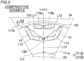
FIG. 3] FIG. 3 is a partial enlarged plan view of one magnetic pole of a rotor core according to a comparative example. - Hereinafter, an embodiment of the present invention will be described with reference to the drawings.
- A
rotor core 10 according to the embodiment will be described with reference toFIGS. 1 and 2 . - In the following description, the "axial direction" means the direction along a rotation axis C1 of the rotor core 10 (laminated core 11) and means the Z direction in the drawings. The "radial direction" means the radial direction of the rotor core 10 (R1 direction or R2 direction), and the "circumferential direction" means the circumferential direction of the rotor core 10 (E1 direction or E2 direction).
- First, the structure of the
rotor core 10 of the present embodiment will be described with reference toFIGS. 1 and 2 . - As shown in
FIG. 1 , a rotatingelectrical machine 100 includes a rotor 1 and astator 2. The rotor 1 and thestator 2 are each formed in an annular shape. The rotor 1 is disposed radially inward of thestator 2 so as to face thestator 2. That is, in the present embodiment, the rotatingelectrical machine 100 is configured as an inner rotor type rotating electrical machine. - The rotor 1 includes the
rotor core 10 and a shaft, not shown. Therotor core 10 has ashaft insertion hole 3 into which the shaft, not shown, is inserted. The shaft is connected to an engine, an axle, etc. via a rotational force transmission member such as a gear. For example, the rotatingelectrical machine 100 is configured as a motor, a generator, or a motor generator, and is configured to be mounted on a vehicle. - The
rotor core 10 includes the laminatedcore 11 having an annular shape. The laminatedcore 11 is formed by stacking a plurality ofelectrical steel plates 11a in the axial direction (Z direction). Therotor core 10 further includes a plurality ofpermanent magnets 12. The rotatingelectrical machine 100 is configured as an interior permanent magnet motor (IPM motor). - A plurality of
permanent magnets 12 forms a plurality ofmagnetic poles 20. Each of the plurality ofmagnetic poles 20 is formed by sixpermanent magnets 12 shown inFIG. 2 . As shown inFIG. 1 , in therotor core 10, eightmagnetic poles 20 are arranged circumferentially. The detailed configuration of themagnetic pole 20 will be described later. - The
stator 2 includes astator core 2a and a coil, not shown, disposed in thestator core 2a. Thestator core 2a is composed of, for example, a plurality of electrical steel sheets (silicon steel sheets) stacked on top of each other in the axial direction, and is configured to allow magnetic flux to pass therethrough. The coil is connected to an external power supply unit, and is configured to be supplied with electric power (e.g. three-phase alternating current electric power). The coil is configured to generate a magnetic field when supplied with electric power. The rotor 1 and the shaft, not shown, are configured to rotate with respect to thestator 2 as the engine etc. is driven or the axle is rotated, even when no electric power is supplied to the coil. - The
permanent magnets 12 are rectangular in cross section orthogonal to the axial direction of the rotor core 10 (Z direction). Thepermanent magnets 12 are, for example, neodymium magnets. - Magnet holes (13, 14, 15, 16), which will be described later, of the
laminated core 11 into which thepermanent magnets 12 are inserted are filled with a thermosetting resin material, not shown. The resin material is provided so as to fix thepermanent magnets 12 disposed in the magnet holes (13, 14, 15, 16). - The configuration of each
magnetic pole 20 will be described with reference toFIG. 2 . - As shown in
FIG. 2 , thelaminated core 11 includes amagnet hole 13, amagnet hole 14, amagnet hole 15, and amagnet hole 16. Themagnet hole 13, themagnet hole 14, themagnet hole 15, and themagnet hole 16 are provided in each of the plurality ofmagnetic poles 20. Themagnet hole 13 and themagnet hole 14 are examples of the "one side magnet hole" and the "other side magnet hole" in the claims, respectively. Themagnet hole 15 and themagnet hole 16 are examples of the "intermediate magnet hole" and the "outer magnet hole" in the claims, respectively. - The
magnet hole 13 is provided on one side (E1 side) in the circumferential direction with respect to a d-axis. Themagnet hole 14 is provided on the other side (E2 side) in the circumferential direction with respect to the d-axis. - The
magnet hole 15 is provided between themagnet hole 13 and themagnet hole 14. A plurality of (two in the present embodiment)permanent magnets 12 is inserted into themagnet hole 15. - In the present embodiment, the plurality of
permanent magnets 12 inserted into themagnet hole 15 is arranged in a convex shape pointing radially outward. In other words, the plurality ofpermanent magnets 12 inserted into themagnet hole 15 is arranged in a V-shape pointing radially outward. - Accordingly, as compared to the case where the
magnet hole 15 is provided into which the plurality ofpermanent magnets 12 is inserted so as to be arranged in a convex shape pointing radially inward, a radially outer portion 11d of thelaminated core 11 that is provided radially outward of themagnet hole 15 can be relatively reduced in amount. As a result, it is possible to reduce the stress (radially outward tensile stress) that is applied to abridge portion 33 described later and abridge portion 34 described later due to the centrifugal force that is generated when the rotor 1 is rotated. - In the present embodiment, the
magnet hole 15 is formed by a single hole that is bent into a convex shape pointing radially outward and into which the plurality ofpermanent magnets 12 is inserted. That is, themagnet hole 15 has a V-shape pointing radially outward. Themagnet hole 15 is provided so as to extend across the d-axis. The bend angle 01 of themagnet hole 15 is an angle larger than 90 degrees. - A single hole bent into a convex shape pointing radially outward is thus provided, the plurality of
permanent magnets 12 that is inserted into themagnet hole 15 can be easily arranged in a convex shape pointing radially outward. Since themagnet hole 15 is formed by a single hole, no magnetic path formed between holes is provided in themagnet hole 15 unlike the case where themagnet hole 15 is formed by a plurality of holes. As a result, the magnetic flux flowing radially outward of themagnet hole 15 can be prevented from flowing (leaking) into the radially inner side of thelaminated core 11. - The
permanent magnets 12 are inserted into one side (E1 side) and the other side (E2 side) in the circumferential direction of themagnet hole 15 with respect to the d-axis. Specifically, the twopermanent magnets 12 inserted into themagnet hole 15 are arranged symmetrically with respect to the d-axis. - This can improve the rotational balance of the rotor 1 compared to the case where the
permanent magnet 12 is disposed in only one side of themagnet hole 15 with respect to the d-axis. - In the present embodiment, a
flux barrier 15a is formed between thepermanent magnets 12 inserted into themagnet hole 15. No bridge portion connecting a radially inner portion 11c of thelaminated core 11 and the radially outer portion 11d of thelaminated core 11 is provided between thepermanent magnets 12 inserted into themagnet hole 15. Theflux barrier 15a is provided on the d-axis. Theflux barrier 15a is an example of the "magnetic gap" in the claims. - The
flux barrier 15a can thus prevent the magnetic flux flowing radially outward of themagnet hole 15 from flowing (leaking) into the radially inner side of thelaminated core 11 through between thepermanent magnets 12 inserted into themagnet hole 15. As a result, a reduction in reluctance torque can be prevented. - The
magnet hole 15 includes aflux barrier 15b and aflux barrier 15c. Theflux barrier 15b is provided on the E1 side of thepermanent magnet 12 disposed in the E1 side out of the twopermanent magnets 12 inserted into themagnet hole 15. Theflux barrier 15c is provided on the E2 side of thepermanent magnet 12 disposed in the E2 side out of the twopermanent magnets 12 inserted into themagnet hole 15. - An
inner magnet layer 51 is formed by thepermanent magnet 12 inserted into themagnet hole 13, thepermanent magnet 12 inserted into themagnet hole 14, and the twopermanent magnets 12 inserted into themagnet hole 15. - The
laminated core 11 includes abridge portion 31 and abridge portion 32. Thebridge portion 31 and thebridge portion 32 are provided in each of the plurality ofmagnetic poles 20. Thebridge portion 31 is provided between a radiallyouter end 13a of themagnet hole 13 and an outer edge 11b of thelaminated core 11. Thebridge portion 32 is provided between a radiallyouter end 14a of themagnet hole 14 and the outer edge 11b of thelaminated core 11. Thebridge portion 31 and thebridge portion 32 are examples of the "first outer bridge portion" and the "second outer bridge portion," respectively. - In the present embodiment, the
laminated core 11 includes, in each of the plurality ofmagnetic poles 20, abridge portion 33 provided between themagnet hole 13 and themagnet hole 15 and abridge portion 34 provided between themagnet hole 14 and themagnet hole 15. Specifically, thebridge portion 33 is provided on the one side (E1 side) in the circumferential direction with respect to the d-axis. Thebridge portion 34 is provided on the other side (E2 side) in the circumferential direction with respect to the d-axis. Each of thebridge portion 33 and thebridge portion 34 is provided so as to connect the radially inner portion 11c of thelaminated core 11 and the radially outer portion 11d of thelaminated core 11. Thebridge portion 33 and thebridge portion 34 are examples of the "first inner bridge portion" and the "second inner bridge portion," respectively. - Since the
bridge portion 33 is thus located on the one side in the circumferential direction with respect to the d-axis, the distance L1 between thebridge portion 31 and the bridge portion 33 (seeFIG. 1 ) can be reduced compared to the case where thebridge portion 33 is located on the d-axis. Since thebridge portion 34 is located on the other side in the circumferential direction with respect to the d-axis, the distance L2 between thebridge portion 32 and the bridge portion 34 (seeFIG. 1 ) can be reduced compared to the case where thebridge portion 34 is located on the d-axis. The radially outer portion 11d of thelaminated core 11 can thus be supported by the bridge portions located relatively close to each other. As a result, the radially outer portion 11d of thelaminated core 11 between the bridge portion 31 (bridge portion 32) and the bridge portion 33 (bridge portion 34) can be prevented from being deformed due to the centrifugal force that is generated when the rotor 1 is rotated. The stress that is applied to each of thebridge portion 31 and thebridge portion 32 can be thus reduced. - Moreover, since the laminated core 11 (permanent magnets 12) is supported from the radially inner side by the two bridge portions, namely the
bridge portion 33 and thebridge portion 34, the laminated core 11 (permanent magnets 12) can be more stably and firmly supported compared to the case where the laminated core 11 (permanent magnets 12) is supported from the radially inner side by a single bridge portion. - The
bridge portion 33 and thebridge portion 34 are arranged symmetrically with respect to the d-axis. This can further improve the rotational balance of the rotor 1 compared to the case where thebridge portion 33 and thebridge portion 34 are arranged asymmetrically with respect to the d-axis. - In each of the plurality of
magnetic poles 20, themagnet hole 15 is configured to be symmetrical with respect to the d-axis, and themagnet hole 13 and themagnet hole 14 are provided symmetrically with respect to the d-axis. That is, the entiremagnetic pole 20 is configured to be symmetrical with respect to the d-axis. - In the present embodiment, each of the
bridge portion 33 and thebridge portion 34 is tilted toward the d-axis such that the radial outer sides of thebridge portion 33 and thebridge portion 34 are located closer to the d-axis as viewed in the axial direction (Z1 direction) of thelaminated core 11. That is, each of thebridge portion 33 and thebridge portion 34 is provided such that the extension line of each of thebridge portion 33 and thebridge portion 34 crosses the d-axis at a position radially outward of themagnet hole 15. - When the
rotor core 10 is rotated, a centrifugal force is applied to each part of thelaminated core 11 in the radially outward direction toward the d-axis. Therefore, since the bridge portion 33 (bridge portion 34) is tilted toward the d-axis such that the radial outer side of the bridge portion 33 (bridge portion 34) is located closer to the d-axis as viewed in the axial direction, the stress (tensile stress) due to the centrifugal force generated when the rotor 1 is rotated is applied to the bridge portion 33 (bridge portion 34) in the direction in which the bridge portion 33 (bridge portion 34) extends. As a result, stress in a bending direction (or twisting direction) can be prevented as much as possible from being applied to each of thebridge portion 33 and thebridge portion 34. - Each of the
magnet hole 13 and themagnet hole 14 is provided so as to extend in the radial direction. That is, thepermanent magnets 12 inserted into each of themagnet hole 13 and themagnet hole 14 are provided so as to extend in the radial direction. - In the present embodiment, the
laminated core 11 is configured so that thepermanent magnet 12 inserted into themagnet hole 13, thepermanent magnet 12 inserted into themagnet hole 14, and the plurality ofpermanent magnets 12 inserted into themagnet hole 15 are arranged in a W-shape. - Since the radially
outer end 13a of themagnet hole 13 and the radiallyouter end 14a of themagnet hole 14 can thus be easily located close to the outer edge 1 1b of thelaminated core 11, the radial widths of thebridge portion 31 and thebridge portion 32 can be easily reduced. As a result, the reluctance torque can be prevented from being reduced due to the magnetic flux along the magnet hole 13 (magnet hole 14) flowing in the circumferential direction through thebridge portion 31 and the bridge portion 32 (leaking toward the adjacent magnetic poles 20). Since the plurality ofpermanent magnets 12 is thus arranged in a W-shape (permanent magnets 12 in themagnet hole 15 are arranged in a convex shape pointing radially outward) while preventing a reduction in reluctance torque, stress that is applied to each of the radially inner bridge portions (bridge portion 33 and bridge portion 34) and the radially outer bridge portions (bridge portion 31 and bridge portion 32) can be reduced. - Each of the angle θ2 between the direction in which the
magnet hole 13 extends and the d-axis and the angle θ3 between the direction in which themagnet hole 14 extends and the d-axis is smaller than 1/2 of the bend angle θ1 of themagnet hole 15. The angle θ2 and the angle θ3 are substantially equal. - The
magnet hole 13 includes aflux barrier 13b provided radially outward of thepermanent magnet 12 inserted into themagnet hole 13. Themagnet hole 13 further includes a flux barrier 13c provided radially inward of thepermanent magnet 12 inserted into themagnet hole 13. - The
magnet hole 14 includes aflux barrier 14b provided radially outward of thepermanent magnet 12 inserted into themagnet hole 14. Themagnet hole 14 further includes aflux barrier 14c provided radially inward of thepermanent magnet 12 inserted into themagnet hole 14. - The
magnet hole 16 is provided radially outward of themagnet hole 15. A plurality of (two in the present embodiment)permanent magnets 12 is inserted into themagnet hole 16. - The
magnet hole 16 is provided so that the plurality ofpermanent magnets 12 inserted into themagnet hole 16 is arranged in a convex shape pointing radially outward. In other words, the plurality ofpermanent magnets 12 inserted into themagnet hole 16 is arranged in a V-shape pointing radially outward. - Like the
magnet hole 15, themagnet hole 16 is thus provided so that the plurality ofpermanent magnets 12 inserted therein is arranged in a convex shape pointing radially outward. As a result, the magnetic path between themagnet hole 16 and themagnet hole 15 can be prevented from becoming narrower compared to the case where the plurality ofpermanent magnets 12 inserted into themagnet hole 16 is arranged in a convex shape pointing radially inward. - The
magnet hole 16 includes amagnet hole 16a provided on the one side (E1 side) in the circumferential direction with respect to the d-axis and amagnet hole 16b provided on the other side (E2 side) in the circumferential direction with respect to the d-axis. Onepermanent magnet 12 is inserted into each of themagnet hole 16a and themagnet hole 16b. - A
bridge portion 35 located on the d-axis is provided between themagnet hole 16a and themagnet hole 16b. Thebridge portion 35 is provided so as to extend along the d-axis. - The
magnet hole 16a includes aflux barrier portion 16c provided on one side (E1 side) in the circumferential direction of thepermanent magnet 12 inserted into themagnet hole 16a. Themagnet hole 16b includes aflux barrier portion 16d provided on the other side (E2 side) in the circumferential direction of thepermanent magnet 12 inserted into themagnet hole 16b. - An outer magnet layer 52 is formed by the
permanent magnets 12 inserted into each of themagnet hole 16a and themagnet hole 16b. That is, each of the plurality ofmagnetic poles 20 has a two-layer magnet structure composed of theinner magnet layer 51 and the outer magnet layer 52. With this structure, since magnetic flux flows between theinner magnet layer 51 and the outer magnet layer 52, the reluctance torque can be effectively used. As a result, the number of magnets can be reduced while improving the torque. - The
permanent magnets 12 inserted into each of themagnet hole 16a and themagnet hole 16b have an N pole on their radially outer side and an S pole on their radially inner side. Thepermanent magnets 12 inserted into each of themagnet hole 13 and themagnet hole 14 have an N pole on their d-axis side and an S pole on their q-axis side. Thepermanent magnets 12 inserted into themagnet hole 15 have an N pole on their radially outer side and an S pole on their radially inner side. The above arrangement of the N pole and the S pole is reversed between themagnetic poles 20 adjacent to each other in the circumferential direction. - Each of the distance L1 (see
FIG. 1 ) between thebridge portion 31 and thebridge portion 33 and the distance L2 (seeFIG. 1 ) between thebridge portion 32 and thebridge portion 34 is smaller than the distance L3 (seeFIG. 1 ) between thebridge portion 33 and thebridge portion 34. The distance L1 and the distance L2 are substantially equal. - Stress that is applied to each of the
bridge portion 31 and thebridge portion 32 can thus be reduced compared to the case where each of the distance L1 between thebridge portion 31 and thebridge portion 33 and the distance L2 between thebridge portion 32 and thebridge portion 34 is larger than the distance L3 between thebridge portion 33 and thebridge portion 34. - Next, stress in the rotor core 10 (laminated core 11) of the present embodiment and stress in a rotor core (laminated core 111) of a comparative example (see
FIG. 3 ) will be compared with reference toFIGS. 1 to 3 . - The configuration of the
laminated core 111 of the comparative example will be described. As shown inFIG. 3 , thelaminated core 111 is provided with amagnet hole 113 on the one side (E1 side) in the circumferential direction with respect to the d-axis, and is provided with amagnet hole 114 on the other side (E2 side) in the circumferential direction with respect to the d-axis. Themagnet hole 113 and themagnet hole 114 form a U-shape pointing radially inward. A bridge portion 131 is provided between themagnet hole 113 and anouter edge 111b of thelaminated core 111. Abridge portion 132 is provided between themagnet hole 114 and theouter edge 111b of thelaminated core 111. - A
center bridge 130 located on the d-axis is provided between themagnet hole 113 and themagnet hole 114. Amagnet hole 116a and amagnet hole 116b are provided radially outward of thecenter bridge 130.Permanent magnets 12 inserted into themagnet hole 116a and themagnet hole 116b are arranged in a V-shape. - In this case, the simulation results were obtained that the stress applied to the
bridge portion 31 and thebridge portion 32 during rotation of the rotor 1 of the present embodiment is smaller than the stress applied to the bridge portion 131 and thebridge portion 132 during rotation of the rotor (laminated core 111) of the comparative example. This is because the distance L1 (seeFIG. 1 ) between thebridge portion 31 and thebridge portion 33 and the distance L2 (seeFIG. 1 ) between thebridge portion 32 and thebridge portion 34 is smaller than the distance L11 (seeFIG. 3 ) between the bridge portion 131 and thecenter bridge 130 and the distance L12 (seeFIG. 3 ) between thebridge portion 132 and thecenter bridge 130. - The distance L4 (see
FIG. 1 ) between aninner periphery 11e (seeFIG. 1 ) of thelaminated core 11 and thebridge portion 33 and the distance L5 (seeFIG. 1 ) between theinner periphery 11e (seeFIG. 1 ) and thebridge portion 34 is greater than the distance L13 (seeFIG. 3 ) between aninner periphery 111e (seeFIG. 3 ) of thelaminated core 111 and thecenter bridge 130. - Therefore, the stress that is applied to the
bridge portion 33 and thebridge portion 34 when fastening the shaft (not shown) in theshaft insertion hole 3 can be made smaller than the stress that is applied to thecenter bridge 130 when fastening a shaft in a shaft insertion hole 23 (seeFIG. 3 ) of thelaminated core 111. The stress that is applied to thebridge portion 33 and thebridge portion 34 when fastening the shaft can thus be made relatively small. Therefore, even if therotor core 10 is reduced in size and the distance L4 and the distance L5 are reduced accordingly, the stress that is applied to thebridge portion 33 and thebridge portion 34 can be easily kept within the allowable range. Fastening of the shaft includes shrink fitting, fastening with a nut, etc. - The embodiment disclosed herein should be construed as illustrative in all respects and not restrictive. The scope of the present invention is shown by the claims rather than by the above description of the embodiment, and includes all changes (modifications) that fall within the meaning and scope equivalent to the claims.
- For example, the above embodiment illustrates an example in which each of the magnet hole 13 (one side magnet hole) and the magnet hole 14 (other side magnet hole) extends in the radial direction so that the plurality of
permanent magnets 12 is arranged in a W-shape. However, the present invention is not limited to this. For example, each of themagnet hole 13 and themagnet hole 14 may be tilted at a predetermined angle (e.g., 45 degrees) with respect to the radial direction, and thepermanent magnets 12 may not be arranged in a W-shape. - The above embodiment illustrates an example in which the magnet hole 15 (intermediate magnet hole) is formed by a single hole. However, the present invention is not limited to this. The
magnet hole 15 may be formed by a plurality of holes. In this case, a bridge portion is provided between the holes. - The above embodiment illustrates an example in which four
permanent magnets 12 are arranged in theinner magnet layer 51. However, the present invention is not limited to this. For example, eightpermanent magnets 12 may be arranged in theinner magnet layer 51. In this case, for example, twopermanent magnets 12, fourpermanent magnets 12, and twopermanent magnets 12 are arranged in themagnet hole 13, themagnet hole 15, and themagnet hole 14, respectively. - The above embodiment illustrates an example in which each of the
bridge portion 33 and thebridge portion 34 is tilted toward the d-axis such that the radial outer sides of thebridge portion 33 and thebridge portion 34 are located closer to the d-axis. However, the present invention is not limited to this. Each of thebridge portion 33 and thebridge portion 34 may be provided so as to extend in a direction other than the direction in which the radial outer sides of thebridge portion 33 and thebridge portion 34 are located closer to the d-axis (e.g., a direction along the d-axis). - The above embodiment illustrates an example in which the
laminated core 11 is provided with the magnet hole 16 (outer magnet hole) (outer magnet layer 52). However, the present invention is not limited to this. Thelaminated core 11 may not be provided with the magnet hole 16 (outer magnet layer 52). - The above embodiment illustrates an example of the two-layer magnet structure composed of the outer magnet layer 52 and the
inner magnet layer 51. However, the present invention is not limited to this. Three or more magnet layers may be provided. - The above embodiment illustrates an example in which the
magnet hole 16 is provided so that the plurality ofpermanent magnets 12 inserted into the magnet hole 16 (outer magnet hole) is arranged in a convex shape pointing radially outward. However, the present invention is not limited to this. For example, themagnet hole 16 may be provided so that the plurality ofpermanent magnets 12 inserted into themagnet hole 16 is arranged in a convex shape pointing radially inward or is perpendicular to the radial direction. - The above embodiment illustrates an example in which each of the distance L1 between the bridge portion 31 (first outer bridge portion) and the bridge portion 33 (first inner bridge portion) and the distance L2 between the bridge portion 32 (second outer bridge portion) and the bridge portion 34 (second inner bridge portion) is smaller than the distance L3 between the
bridge portion 33 and thebridge portion 34. However, the present invention is not limited to this. Each of the distance L1 and the distance L2 may be equal to or greater than the distance L3. - 10 ... rotor core, 11 ... laminated core, 11a ... electrical steel plate, 11b ... outer edge, 11c ... radially inner portion, 11d ... radially outer portion, 12 ... permanent magnet, 13 ... magnet hole (one side magnet hole), 13a ... end (end of one side magnet hole), 14 ... magnet hole (other side magnet hole), 14a ... end (end of other side magnet hole), 15 ... magnet hole (intermediate magnet hole), 15a ... flux barrier (magnetic gap), 16 ... magnet hole (outer magnet hole), 20 ... magnetic pole, 31 ... bridge portion (first outer bridge portion), 32 ... bridge portion (second outer bridge portion), 33 ... bridge portion (first inner bridge portion), 34 ... bridge portion (second inner bridge portion)
Claims (5)
- A rotor core, comprising:an annular laminated core formed by stacking a plurality of electrical steel sheets; anda plurality of permanent magnets forming a plurality of magnetic poles arranged circumferentially, whereinthe laminated core includes, in each of the plurality of magnetic poles, a one side magnet hole that is provided on one side in a circumferential direction with respect to a d-axis and into which the permanent magnet is inserted, an other side magnet hole that is provided on the other side in the circumferential direction with respect to the d-axis and into which the permanent magnet is inserted, an intermediate magnet hole that is provided between the one side magnet hole and the other side magnet hole and into which a plurality of the permanent magnets is inserted so as to be arranged in a convex shape pointing radially outward, a first outer bridge portion provided between a radially outer end of the one side magnet hole and an outer edge of the laminated core, a second outer bridge portion provided between a radially outer end of the other side magnet hole and the outer edge, a first inner bridge portion provided between the one side magnet hole and the intermediate magnet hole and connecting a radially inner portion of the laminated core and a radially outer portion of the laminated core, and a second inner bridge portion provided between the other side magnet hole and the intermediate magnet hole and connecting the radially inner portion and the radially outer portion.
- The rotor core according to claim 1, whereineach of the one side magnet hole and the other side magnet hole is provided so as to extend in a radial direction, andthe laminated core is configured in such a manner that the permanent magnet inserted into the one side magnet hole, the permanent magnet inserted into the other side magnet hole, and the plurality of permanent magnets inserted into the intermediate magnet hole are arranged in a W-shape.
- The rotor core according to claim 2, whereinthe intermediate magnet hole is formed by a single hole that is bent into a convex shape pointing radially outward and into which the plurality of permanent magnets is inserted, anda magnetic gap is formed between the permanent magnets inserted into the intermediate magnet hole.
- The rotor core according to any one of claims 1 to 3, wherein each of the first inner bridge portion and the second inner bridge portion is tilted toward the d-axis in such a manner that radial outer sides of the first inner bridge portion and the second inner bridge portion are located closer to the d-axis as viewed in an axial direction of the laminated core.
- The rotor core according to any one of claims 1 to 4, wherein the laminated core includes an outer magnet hole that is provided radially outward from the intermediate magnet hole and into which a plurality of the permanent magnets is inserted so as to be arranged in a convex shape pointing radially outward.
Applications Claiming Priority (2)
| Application Number | Priority Date | Filing Date | Title |
|---|---|---|---|
| JP2021002282A JP7478104B2 (en) | 2021-01-08 | 2021-01-08 | Rotor core |
| PCT/JP2021/047306 WO2022149458A1 (en) | 2021-01-08 | 2021-12-21 | Rotor core |
Publications (2)
| Publication Number | Publication Date |
|---|---|
| EP4220899A1 true EP4220899A1 (en) | 2023-08-02 |
| EP4220899A4 EP4220899A4 (en) | 2024-04-17 |
Family
ID=82357305
Family Applications (1)
| Application Number | Title | Priority Date | Filing Date |
|---|---|---|---|
| EP21917678.1A Pending EP4220899A4 (en) | 2021-01-08 | 2021-12-21 | ROTOR CORE |
Country Status (5)
| Country | Link |
|---|---|
| US (1) | US12519353B2 (en) |
| EP (1) | EP4220899A4 (en) |
| JP (1) | JP7478104B2 (en) |
| CN (1) | CN116636116A (en) |
| WO (1) | WO2022149458A1 (en) |
Families Citing this family (7)
| Publication number | Priority date | Publication date | Assignee | Title |
|---|---|---|---|---|
| DE102021210184A1 (en) * | 2021-09-15 | 2023-03-16 | Robert Bosch Gesellschaft mit beschränkter Haftung | Rotor of an electrical machine |
| KR102670967B1 (en) * | 2022-08-30 | 2024-05-31 | 엘지전자 주식회사 | Flux concentrate type motor |
| EP4607765A4 (en) * | 2022-10-18 | 2026-01-21 | Aisin Corp | ROTOR FOR ELECTRIC LATHE |
| JP7754046B2 (en) * | 2022-10-18 | 2025-10-15 | 株式会社アイシン | Rotor for rotating electrical machine |
| JP2024113995A (en) * | 2023-02-10 | 2024-08-23 | 株式会社アイシン | Rotor for rotating electrical machine |
| CN116317249B (en) * | 2023-04-20 | 2024-05-24 | 小米汽车科技有限公司 | Rotor punching sheet, motor rotor, motor and vehicle |
| EP4572095A1 (en) * | 2023-12-12 | 2025-06-18 | Weg Equipamentos Elétricos S/A | Rotor for a rotating electric machine and rotating electric machine |
Family Cites Families (127)
| Publication number | Priority date | Publication date | Assignee | Title |
|---|---|---|---|---|
| US2913607A (en) * | 1957-01-16 | 1959-11-17 | Allis Louis Co | Synchronous induction motor |
| US3840763A (en) * | 1973-07-09 | 1974-10-08 | Gen Electric | Low flux density permanent magnet field configuration |
| US4327302A (en) * | 1979-09-21 | 1982-04-27 | General Electric Company | Electronically commutated motor, stationary and rotatable assemblies therefore, and lamination |
| US4922152A (en) * | 1988-07-27 | 1990-05-01 | Siemens Energy & Automation, Inc. | Synchronous machine rotor lamination |
| US5117553A (en) * | 1990-06-25 | 1992-06-02 | General Electric Company | Method of assembling rotor magnets |
| US5159220A (en) * | 1990-06-25 | 1992-10-27 | General Electric Company | Realizations of folded magnet AC motors |
| US6087751A (en) | 1997-07-01 | 2000-07-11 | Kabushiki Kaisha Toshiba | Reluctance type rotating machine with permanent magnets |
| JP3290392B2 (en) * | 1997-10-31 | 2002-06-10 | 株式会社東芝 | Permanent magnet type reluctance type rotating electric machine |
| JP3818340B2 (en) * | 1997-09-26 | 2006-09-06 | 株式会社富士通ゼネラル | Permanent magnet motor |
| JP3906883B2 (en) * | 1997-10-29 | 2007-04-18 | 株式会社富士通ゼネラル | Permanent magnet motor |
| KR200210795Y1 (en) * | 1998-03-20 | 2001-02-01 | 윤종용 | Motor for Reclamated Eternatiy Magnet |
| JP2000050542A (en) * | 1998-07-23 | 2000-02-18 | Okuma Corp | Reluctance motor |
| DE19933009A1 (en) * | 1998-07-24 | 2000-02-10 | Matsushita Electric Industrial Co Ltd | Electric motor e.g. for automobile air conditioning unit, has rotor core provided with slits for reception of internal permanent magnets with non-magnetic section between each permanent magnet and rotor periphery |
| JP4089072B2 (en) * | 1998-10-23 | 2008-05-21 | 三菱電機株式会社 | Permanent magnet embedded motor |
| JP2000156947A (en) * | 1998-11-17 | 2000-06-06 | Yukio Kinoshita | Magnet type motor and generator |
| EP1014542B1 (en) * | 1998-12-25 | 2005-11-16 | Matsushita Electric Industrial Co., Ltd. | Motor having a rotor with interior split-permanent-magnet |
| EP1414131B1 (en) * | 1999-02-22 | 2011-11-23 | Kabushiki Kaisha Toshiba | Permanent magnet and reluctance type rotating machine |
| FR2791483B1 (en) * | 1999-03-22 | 2004-06-25 | Valeo Equip Electr Moteur | ROTATING MACHINE COMPRISING MAGNETS OF DIFFERENT COMPOSITIONS |
| JP2001136690A (en) * | 1999-11-10 | 2001-05-18 | Isuzu Motors Ltd | Rotating machine rotor |
| JP2001314052A (en) * | 2000-02-25 | 2001-11-09 | Nissan Motor Co Ltd | Rotor structure of synchronous motor |
| JP4363746B2 (en) * | 2000-05-25 | 2009-11-11 | 株式会社東芝 | Permanent magnet type reluctance type rotating electrical machine |
| JP2002044915A (en) * | 2000-07-27 | 2002-02-08 | Yamaha Motor Co Ltd | Embedded magnet rotor and filling method |
| JP2002112476A (en) * | 2000-09-28 | 2002-04-12 | Hitachi Ltd | Permanent magnet type rotating electric machine |
| JP2003032926A (en) * | 2001-07-10 | 2003-01-31 | Teijin Seiki Co Ltd | Permanent magnet type motor |
| US7042127B2 (en) * | 2003-04-02 | 2006-05-09 | Nidec Sankyo Corporation | Permanent magnet embedded motor |
| JP3903956B2 (en) * | 2003-05-23 | 2007-04-11 | 日産自動車株式会社 | Multi-axis multilayer motor |
| JP2004357489A (en) * | 2003-05-28 | 2004-12-16 | Akira Chiba | Unidirectionally magnetized permanent magnet motor |
| TWI224412B (en) * | 2003-07-30 | 2004-11-21 | Ming-Tsung Chu | Rotor structure of line-start permanent magnet synchronous motor |
| JP2005073450A (en) * | 2003-08-27 | 2005-03-17 | Matsushita Electric Ind Co Ltd | Motor generator |
| JP2005124386A (en) * | 2003-09-22 | 2005-05-12 | Nissan Motor Co Ltd | Rotor using low iron loss electromagnetic steel sheet, rotor manufacturing method, laser peening method and laser peening apparatus |
| JP4449035B2 (en) * | 2004-03-10 | 2010-04-14 | 日立オートモティブシステムズ株式会社 | Permanent magnet rotating electric machine for electric vehicles |
| JP2006014457A (en) * | 2004-06-24 | 2006-01-12 | Fanuc Ltd | Synchronous motor |
| JP4574297B2 (en) * | 2004-09-13 | 2010-11-04 | 日産自動車株式会社 | Rotating electrical machine rotor |
| JP2006288183A (en) * | 2005-03-09 | 2006-10-19 | Nissan Motor Co Ltd | Electric motor |
| US7705503B2 (en) * | 2005-09-07 | 2010-04-27 | Kabushiki Kaisha Toshiba | Rotating electrical machine |
| US7436095B2 (en) * | 2005-10-31 | 2008-10-14 | Caterpillar Inc. | Rotary electric machine |
| US7705504B2 (en) * | 2005-11-07 | 2010-04-27 | Asmo Co., Ltd. | Embedded magnet type motor |
| US7489062B2 (en) * | 2005-11-14 | 2009-02-10 | General Electric Company | Synchronous reluctance machine with a novel rotor topology |
| US7719153B2 (en) * | 2005-12-21 | 2010-05-18 | Ut-Battelle, Llc | Permanent magnet machine and method with reluctance poles and non-identical PM poles for high density operation |
| US20070152527A1 (en) * | 2005-12-23 | 2007-07-05 | Okuma Corporation | Reluctance motor |
| JP5259927B2 (en) | 2006-03-31 | 2013-08-07 | 日立オートモティブシステムズ株式会社 | Permanent magnet rotating electric machine |
| US20070284960A1 (en) * | 2006-06-12 | 2007-12-13 | Remy International, Inc. | Magnet for a dynamoelectric machine, dynamoelectric machine and method |
| FI119457B (en) * | 2006-08-31 | 2008-11-14 | Abb Oy | Rotor for a permanently magnetized electric machine |
| SE530697C2 (en) * | 2006-12-19 | 2008-08-19 | Bae Systems Haegglunds Ab | Rotor for an electric motor, rotor plates for the construction of the rotor, and an electric motor with such a rotor |
| DE102008020138A1 (en) * | 2007-04-27 | 2008-10-30 | Asmo Co., Ltd., Kosai | Motor with embedded magnet |
| US7791236B2 (en) * | 2007-08-16 | 2010-09-07 | Ford Global Technologies, Llc | Permanent magnet machine |
| US7808143B2 (en) * | 2007-10-24 | 2010-10-05 | Rechi Precision Co., Ltd. | Permanent magnet motor |
| JP5238231B2 (en) * | 2007-11-28 | 2013-07-17 | 株式会社東芝 | Rotating electrical machine rotor |
| FR2932618B1 (en) * | 2008-06-16 | 2010-11-19 | Leroy Somer Moteurs | ROTOR WITH PERMANENT MAGNETS AND ROTATING MACHINE COMPRISING SUCH A ROTOR |
| JP4627788B2 (en) * | 2008-06-27 | 2011-02-09 | 株式会社日立製作所 | Permanent magnet rotating electric machine |
| JP2010034365A (en) * | 2008-07-30 | 2010-02-12 | Hitachi Ltd | Rotating machine with sintered magnet, and method of manufacturing sintered magnet |
| US7902710B2 (en) * | 2008-10-01 | 2011-03-08 | Caterpillar Inc. | Electric machine |
| US8536748B2 (en) * | 2008-11-11 | 2013-09-17 | Ford Global Technologies, Llc | Permanent magnet machine with different pole arc angles |
| CN102171909B (en) * | 2008-11-19 | 2013-08-28 | 三菱电机株式会社 | Rotor of motor and motor and fan and compressor |
| CN201294443Y (en) * | 2008-12-01 | 2009-08-19 | 东元总合科技(杭州)有限公司 | Permanent magnet self-startup synchronous motor rotor |
| US8174158B2 (en) * | 2009-02-20 | 2012-05-08 | GM Global Technology Operations LLC | Methods and apparatus for a permanent magnet machine with asymmetrical rotor magnets |
| US8350434B2 (en) * | 2009-02-27 | 2013-01-08 | Hitachi, Ltd. | Permanent magnet type rotary electric machine |
| KR101021120B1 (en) * | 2009-07-14 | 2011-03-14 | 한양대학교 산학협력단 | Rotor for high speed motor |
| CN102025248B (en) * | 2009-09-18 | 2014-03-12 | 德昌电机(深圳)有限公司 | Motor used for power system of electric vehicle |
| DE102009050991A1 (en) * | 2009-10-28 | 2011-05-05 | Bayerische Motoren Werke Aktiengesellschaft | Electric drive machine for a vehicle |
| JP5260563B2 (en) * | 2010-01-07 | 2013-08-14 | 株式会社日立製作所 | Permanent magnet generator or motor |
| MY168668A (en) * | 2010-02-08 | 2018-11-29 | Mitsubishi Electric Corp | Rotor of permanent magnet embedded motor, blower, and compressor |
| JP5502571B2 (en) * | 2010-04-09 | 2014-05-28 | 株式会社東芝 | Permanent magnet rotating electric machine |
| JP5663936B2 (en) | 2010-04-14 | 2015-02-04 | 富士電機株式会社 | Permanent magnet rotating electric machine |
| US8564168B2 (en) * | 2010-05-24 | 2013-10-22 | Remy Technologies, L.L.C. | Rotor lamination assembly |
| JP2011254677A (en) * | 2010-06-04 | 2011-12-15 | Toyota Motor Corp | Rotor for motor and method for manufacturing the same |
| JP2013529887A (en) * | 2010-07-02 | 2013-07-22 | エー ビー ビー リサーチ リミテッド | Rotor disk with spoke openings |
| CN103026585B (en) * | 2010-07-23 | 2014-07-09 | 丰田自动车株式会社 | Rotor and IPM motor |
| JP5331761B2 (en) * | 2010-08-09 | 2013-10-30 | 株式会社日立製作所 | Permanent magnet rotating electric machine |
| US8749103B2 (en) * | 2010-09-15 | 2014-06-10 | Remy Technologies, L.L.C. | Permanent magnet rotor for electric machine |
| JP5480176B2 (en) * | 2011-02-03 | 2014-04-23 | アイシン・エィ・ダブリュ株式会社 | Rotating machine rotor |
| JP5447418B2 (en) * | 2011-03-28 | 2014-03-19 | 株式会社豊田自動織機 | Rotating electric machine permanent magnet embedded rotor and rotating electric machine |
| KR101786922B1 (en) * | 2011-05-26 | 2017-10-18 | 삼성전자주식회사 | Rotor and driving motor |
| JP5773196B2 (en) * | 2011-07-19 | 2015-09-02 | アイシン・エィ・ダブリュ株式会社 | Rotating electric machine |
| CN102780291A (en) * | 2011-08-05 | 2012-11-14 | 珠海格力电器股份有限公司 | Motor rotor and motor with same |
| EP2568578A3 (en) * | 2011-09-07 | 2017-12-06 | Samsung Electronics Co., Ltd. | Motor and washing machine having the same |
| JP5863410B2 (en) * | 2011-11-16 | 2016-02-16 | 信越化学工業株式会社 | Rotor and spoke type IPM permanent magnet rotating machine |
| US8860275B2 (en) * | 2011-12-09 | 2014-10-14 | GM Global Technology Operations LLC | Multi-layer arc-shaped permanent magnet machine with reduced rotational stress |
| CN103166345B (en) * | 2011-12-12 | 2017-12-08 | 德昌电机(深圳)有限公司 | Brushless electric machine and its rotor |
| JP5752272B2 (en) * | 2011-12-26 | 2015-07-22 | 三菱電機株式会社 | Rotor and motor |
| DE102013201353A1 (en) * | 2012-02-10 | 2013-08-14 | Ksb Aktiengesellschaft | Rotor and reluctance motor |
| JP5594303B2 (en) * | 2012-02-13 | 2014-09-24 | 株式会社安川電機 | Rotating electric machine |
| FR2987184B1 (en) * | 2012-02-20 | 2016-07-29 | Moteurs Leroy-Somer | ROTOR OF ROTATING ELECTRIC MACHINE WITH FLOW CONCENTRATION. |
| US20130249342A1 (en) * | 2012-03-20 | 2013-09-26 | Kollmorgen Corporation | Cantilevered Rotor Magnet Support |
| US9641032B2 (en) * | 2012-03-23 | 2017-05-02 | Mitsubishi Heavy Industries Automotive Thermal Systems Co., Ltd. | Motor having magnets embedded in a rotor and electric compressor using same |
| JP5948127B2 (en) * | 2012-04-23 | 2016-07-06 | 日立オートモティブシステムズ株式会社 | Permanent magnet rotating electric machine and electric vehicle using the same |
| JP5876147B2 (en) * | 2012-05-28 | 2016-03-02 | 株式会社日立産機システム | Compound torque type rotating electrical machine |
| US8664823B2 (en) * | 2012-05-30 | 2014-03-04 | GM Global Technology Operations LLC | Magnetic barrier for minimizing demagnetization in bi-permanent magnet synchronous machines |
| JP5921685B2 (en) * | 2012-06-26 | 2016-05-24 | 三菱電機株式会社 | Permanent magnet embedded electric motor, compressor, and refrigeration air conditioner |
| EP2680401B1 (en) * | 2012-06-29 | 2020-09-02 | GE Renewable Technologies Wind B.V. | Permanent magnet rotor |
| JP6135967B2 (en) * | 2012-08-07 | 2017-05-31 | 日本電産株式会社 | Rotor, motor, and method of manufacturing rotor |
| US8760025B2 (en) * | 2012-08-09 | 2014-06-24 | GM Global Technologies Operations LLC | Interior permanent magnet machine having off axis centered arc geometry |
| US9490673B2 (en) * | 2012-08-16 | 2016-11-08 | Mitsuba Corporation | Rotor of magnet-assisted reluctance motor and brushless motor |
| JP2014103741A (en) * | 2012-11-19 | 2014-06-05 | Jtekt Corp | Magnet embedded type rotor |
| JP2014155415A (en) * | 2013-02-13 | 2014-08-25 | Jtekt Corp | Embedded magnet rotor and method of manufacturing embedded magnet rotor |
| CN104242509B (en) | 2013-06-05 | 2017-08-04 | 上海欧普斯达光纤通信设备有限公司 | A kind of permanent magnetism is combined excitatory synchronous electric motor rotor |
| KR102073005B1 (en) * | 2013-07-17 | 2020-02-04 | 삼성전자주식회사 | Motor |
| WO2015037127A1 (en) * | 2013-09-13 | 2015-03-19 | 三菱電機株式会社 | Permanent magnet-embedded electric motor, compressor, and refrigerating and air-conditioning device |
| WO2015076045A1 (en) * | 2013-11-20 | 2015-05-28 | 日立オートモティブシステムズ株式会社 | Rotary electric machine and electric vehicle provided with same |
| JP6215041B2 (en) * | 2013-12-20 | 2017-10-18 | U−Mhiプラテック株式会社 | motor |
| CN104600938B (en) * | 2013-12-25 | 2016-03-09 | 珠海格力节能环保制冷技术研究中心有限公司 | Magneto |
| JP6147661B2 (en) * | 2013-12-27 | 2017-06-14 | 日立オートモティブシステムズ株式会社 | Rotor, permanent magnet type rotating electric machine including the same, electric drive system, electric vehicle |
| JP2015159706A (en) * | 2014-01-22 | 2015-09-03 | 日本精工株式会社 | Electric motor, electric power steering device, and vehicle |
| JP6237412B2 (en) * | 2014-03-31 | 2017-11-29 | ダイキン工業株式会社 | Rotor structure of embedded magnet type rotating electrical machine |
| FR3019948B1 (en) * | 2014-04-10 | 2017-12-22 | Moteurs Leroy-Somer | ROTOR OF ELECTRIC ROTATING MACHINE. |
| JP6424363B2 (en) * | 2014-10-17 | 2018-11-21 | 株式会社明電舎 | Magnet embedded motor |
| US20160190879A1 (en) * | 2014-12-30 | 2016-06-30 | Hiwin Mikrosystem Corp. | Interior-permanent-magnet motor structure |
| WO2016115722A1 (en) * | 2015-01-23 | 2016-07-28 | 浙江迈雷科技有限公司 | Permanent magnet synchronous motor |
| ITUB20150608A1 (en) * | 2015-04-14 | 2016-10-14 | Ge Avio Srl | METHOD OF REALIZATION OF A ROTOR STRUCTURE OF A SYNCHRONOUS RELUCTANCE ELECTRIC MACHINE, AND RELATED RELUCTANCE SYNCHRONOUS ELECTRICAL MACHINE |
| WO2017154156A1 (en) * | 2016-03-09 | 2017-09-14 | 三菱重工業株式会社 | Salient-pole rotor, and rotor manufacturing method |
| US10439456B2 (en) * | 2016-04-25 | 2019-10-08 | General Electric Company | Sleeve rotor synchronous reluctance electric machine |
| US10211690B2 (en) * | 2016-04-28 | 2019-02-19 | Faraday & Future Inc. | IPM machine with specialized rotor for automotive electric vehicles |
| JP6571050B2 (en) * | 2016-06-29 | 2019-09-04 | 株式会社東芝 | Synchronous reluctance rotary electric machine |
| US10516307B2 (en) * | 2016-08-30 | 2019-12-24 | Hamilton Sundstrand Corporation | Interior permanent magnet motor/rotor with curved and spoke-type permanent magnets |
| JP6709712B2 (en) * | 2016-10-07 | 2020-06-17 | 東芝産業機器システム株式会社 | Synchronous reluctance type rotating electric machine |
| GB201619857D0 (en) | 2016-11-24 | 2017-01-11 | Jaguar Land Rover Ltd | Electric machine apparatus |
| JP2018129938A (en) | 2017-02-08 | 2018-08-16 | 本田技研工業株式会社 | Rotating electric machine |
| CN110603716B (en) * | 2017-05-01 | 2022-11-18 | 三菱电机株式会社 | Rotor, motor, compressor, and air conditioner |
| US10715017B2 (en) * | 2017-06-02 | 2020-07-14 | Hamilton Sundstrand Corporation | Hybrid synchronous machines |
| JP6879140B2 (en) | 2017-09-15 | 2021-06-02 | トヨタ自動車株式会社 | Rotating machine |
| CN108023421B (en) * | 2017-12-21 | 2024-05-28 | 珠海格力电器股份有限公司 | Motor rotor and permanent magnet motor |
| CN108336842B (en) * | 2018-03-16 | 2020-10-16 | 珠海格力节能环保制冷技术研究中心有限公司 | Rotor structure, permanent magnet auxiliary synchronous reluctance motor and electric automobile |
| JP6685634B1 (en) | 2018-10-30 | 2020-04-22 | 三菱電機株式会社 | Rotating electric machine |
| CN209072186U (en) | 2018-12-20 | 2019-07-05 | 卧龙电气南阳防爆集团股份有限公司 | A kind of level-one efficiency flame-proof type asynchronous starting three-phase permanent-magnetic synchronous motors |
| CN110149015B (en) * | 2019-06-19 | 2025-05-16 | 珠海格力电器股份有限公司 | Direct start synchronous reluctance motor rotor structure, motor |
| JP7415871B2 (en) * | 2020-10-22 | 2024-01-17 | トヨタ自動車株式会社 | rotating electric machine |
| US11955843B2 (en) * | 2021-12-22 | 2024-04-09 | Abb Schweiz Ag | Synchronous reluctance motor |
-
2021
- 2021-01-08 JP JP2021002282A patent/JP7478104B2/en active Active
- 2021-12-21 EP EP21917678.1A patent/EP4220899A4/en active Pending
- 2021-12-21 WO PCT/JP2021/047306 patent/WO2022149458A1/en not_active Ceased
- 2021-12-21 CN CN202180084724.7A patent/CN116636116A/en active Pending
- 2021-12-21 US US18/034,809 patent/US12519353B2/en active Active
Also Published As
| Publication number | Publication date |
|---|---|
| CN116636116A (en) | 2023-08-22 |
| WO2022149458A1 (en) | 2022-07-14 |
| JP2022107370A (en) | 2022-07-21 |
| EP4220899A4 (en) | 2024-04-17 |
| JP7478104B2 (en) | 2024-05-02 |
| US12519353B2 (en) | 2026-01-06 |
| US20230412018A1 (en) | 2023-12-21 |
Similar Documents
| Publication | Publication Date | Title |
|---|---|---|
| US12519353B2 (en) | Rotor core with plurality of permanent magnets and magnet holes with bridges between magnets/magnet holes | |
| US9595851B2 (en) | Rotary electric machine | |
| EP3514927B1 (en) | Rotor and reluctance motor | |
| EP1813010B1 (en) | Design of the magnet and webs in interior permanent magent rotors | |
| US8878410B2 (en) | Rotor with reinforcing portions for an electric rotating machine | |
| US11190070B2 (en) | Rotor for rotating electrical machine | |
| US12283848B2 (en) | Rotor for rotary electric machine | |
| EP3890161B1 (en) | Rotating electrical machine | |
| JP7758062B2 (en) | Rotor of an electric rotating machine and electric rotating machine including said rotor | |
| CN111052546A (en) | Rotor of rotating electric machine | |
| CN114651383B (en) | Rotary electric machine | |
| EP3823136A1 (en) | Rotor for a synchronous machine | |
| EP2626977A2 (en) | Rotary electric machine | |
| US12519356B2 (en) | Rotor and rotating electric machine | |
| EP4047788B1 (en) | Rotary electric machine | |
| US11404924B2 (en) | Rotor | |
| JP7124247B1 (en) | Rotor of rotary electric machine | |
| JP2023102516A (en) | Rotor and rotary electric machine | |
| JP2023102517A (en) | Rotor and rotary electric machine | |
| US20250070605A1 (en) | Rotor for rotating electrical machine | |
| US20250364856A1 (en) | Rotating Electrical Machine | |
| US20250309709A1 (en) | Rotor for rotating electrical machine | |
| EP4708636A1 (en) | Permanent magnet rotor | |
| JP7766803B2 (en) | permanent magnet synchronous motor | |
| EP4468565A1 (en) | Rotating electric machine |
Legal Events
| Date | Code | Title | Description |
|---|---|---|---|
| STAA | Information on the status of an ep patent application or granted ep patent |
Free format text: STATUS: THE INTERNATIONAL PUBLICATION HAS BEEN MADE |
|
| PUAI | Public reference made under article 153(3) epc to a published international application that has entered the european phase |
Free format text: ORIGINAL CODE: 0009012 |
|
| STAA | Information on the status of an ep patent application or granted ep patent |
Free format text: STATUS: REQUEST FOR EXAMINATION WAS MADE |
|
| 17P | Request for examination filed |
Effective date: 20230428 |
|
| AK | Designated contracting states |
Kind code of ref document: A1 Designated state(s): AL AT BE BG CH CY CZ DE DK EE ES FI FR GB GR HR HU IE IS IT LI LT LU LV MC MK MT NL NO PL PT RO RS SE SI SK SM TR |
|
| A4 | Supplementary search report drawn up and despatched |
Effective date: 20240315 |
|
| DAV | Request for validation of the european patent (deleted) | ||
| DAX | Request for extension of the european patent (deleted) | ||
| RIC1 | Information provided on ipc code assigned before grant |
Ipc: H02K 1/276 20220101AFI20240311BHEP |