EP4220828A1 - Battery pack - Google Patents
Battery pack Download PDFInfo
- Publication number
- EP4220828A1 EP4220828A1 EP21870984.8A EP21870984A EP4220828A1 EP 4220828 A1 EP4220828 A1 EP 4220828A1 EP 21870984 A EP21870984 A EP 21870984A EP 4220828 A1 EP4220828 A1 EP 4220828A1
- Authority
- EP
- European Patent Office
- Prior art keywords
- flow channel
- temperature adjustment
- bottom plate
- confluence
- liquid
- Prior art date
- Legal status (The legal status is an assumption and is not a legal conclusion. Google has not performed a legal analysis and makes no representation as to the accuracy of the status listed.)
- Granted
Links
Images


Classifications
-
- H—ELECTRICITY
- H01—ELECTRIC ELEMENTS
- H01M—PROCESSES OR MEANS, e.g. BATTERIES, FOR THE DIRECT CONVERSION OF CHEMICAL ENERGY INTO ELECTRICAL ENERGY
- H01M10/00—Secondary cells; Manufacture thereof
- H01M10/60—Heating or cooling; Temperature control
- H01M10/65—Means for temperature control structurally associated with the cells
- H01M10/656—Means for temperature control structurally associated with the cells characterised by the type of heat-exchange fluid
- H01M10/6567—Liquids
- H01M10/6568—Liquids characterised by flow circuits, e.g. loops, located externally to the cells or cell casings
-
- H—ELECTRICITY
- H01—ELECTRIC ELEMENTS
- H01M—PROCESSES OR MEANS, e.g. BATTERIES, FOR THE DIRECT CONVERSION OF CHEMICAL ENERGY INTO ELECTRICAL ENERGY
- H01M10/00—Secondary cells; Manufacture thereof
- H01M10/60—Heating or cooling; Temperature control
- H01M10/61—Types of temperature control
- H01M10/617—Types of temperature control for achieving uniformity or desired distribution of temperature
-
- H—ELECTRICITY
- H01—ELECTRIC ELEMENTS
- H01M—PROCESSES OR MEANS, e.g. BATTERIES, FOR THE DIRECT CONVERSION OF CHEMICAL ENERGY INTO ELECTRICAL ENERGY
- H01M10/00—Secondary cells; Manufacture thereof
- H01M10/60—Heating or cooling; Temperature control
- H01M10/61—Types of temperature control
- H01M10/613—Cooling or keeping cold
-
- H—ELECTRICITY
- H01—ELECTRIC ELEMENTS
- H01M—PROCESSES OR MEANS, e.g. BATTERIES, FOR THE DIRECT CONVERSION OF CHEMICAL ENERGY INTO ELECTRICAL ENERGY
- H01M10/00—Secondary cells; Manufacture thereof
- H01M10/60—Heating or cooling; Temperature control
- H01M10/65—Means for temperature control structurally associated with the cells
- H01M10/655—Solid structures for heat exchange or heat conduction
- H01M10/6554—Rods or plates
-
- H—ELECTRICITY
- H01—ELECTRIC ELEMENTS
- H01M—PROCESSES OR MEANS, e.g. BATTERIES, FOR THE DIRECT CONVERSION OF CHEMICAL ENERGY INTO ELECTRICAL ENERGY
- H01M10/00—Secondary cells; Manufacture thereof
- H01M10/60—Heating or cooling; Temperature control
- H01M10/65—Means for temperature control structurally associated with the cells
- H01M10/655—Solid structures for heat exchange or heat conduction
- H01M10/6556—Solid parts with flow channel passages or pipes for heat exchange
-
- H—ELECTRICITY
- H01—ELECTRIC ELEMENTS
- H01M—PROCESSES OR MEANS, e.g. BATTERIES, FOR THE DIRECT CONVERSION OF CHEMICAL ENERGY INTO ELECTRICAL ENERGY
- H01M50/00—Constructional details or processes of manufacture of the non-active parts of electrochemical cells other than fuel cells, e.g. hybrid cells
- H01M50/20—Mountings; Secondary casings or frames; Racks, modules or packs; Suspension devices; Shock absorbers; Transport or carrying devices; Holders
- H01M50/204—Racks, modules or packs for multiple batteries or multiple cells
-
- H—ELECTRICITY
- H01—ELECTRIC ELEMENTS
- H01M—PROCESSES OR MEANS, e.g. BATTERIES, FOR THE DIRECT CONVERSION OF CHEMICAL ENERGY INTO ELECTRICAL ENERGY
- H01M50/00—Constructional details or processes of manufacture of the non-active parts of electrochemical cells other than fuel cells, e.g. hybrid cells
- H01M50/20—Mountings; Secondary casings or frames; Racks, modules or packs; Suspension devices; Shock absorbers; Transport or carrying devices; Holders
- H01M50/204—Racks, modules or packs for multiple batteries or multiple cells
- H01M50/207—Racks, modules or packs for multiple batteries or multiple cells characterised by their shape
- H01M50/209—Racks, modules or packs for multiple batteries or multiple cells characterised by their shape adapted for prismatic or rectangular cells
-
- Y—GENERAL TAGGING OF NEW TECHNOLOGICAL DEVELOPMENTS; GENERAL TAGGING OF CROSS-SECTIONAL TECHNOLOGIES SPANNING OVER SEVERAL SECTIONS OF THE IPC; TECHNICAL SUBJECTS COVERED BY FORMER USPC CROSS-REFERENCE ART COLLECTIONS [XRACs] AND DIGESTS
- Y02—TECHNOLOGIES OR APPLICATIONS FOR MITIGATION OR ADAPTATION AGAINST CLIMATE CHANGE
- Y02E—REDUCTION OF GREENHOUSE GAS [GHG] EMISSIONS, RELATED TO ENERGY GENERATION, TRANSMISSION OR DISTRIBUTION
- Y02E60/00—Enabling technologies; Technologies with a potential or indirect contribution to GHG emissions mitigation
- Y02E60/10—Energy storage using batteries
Definitions
- the present disclosure relates to the technical field of batteries, and particularly to a battery pack.
- a bottom plate of a battery pack in related art generally has a serpentine flow channel, and liquid inlet and outlet pipes are located at a head and tail end of the serpentine flow channel.
- the temperature of a head flow channel section near the liquid inlet pipe is low, leading to a good cooling effect on cells at a corresponding position; and the temperature of a tail flow channel section near the liquid outlet pipe is high, causing a poor cooling effect on cells at a corresponding position. Therefore, the overall cooling uniformity of the battery pack is poor.
- the present disclosure provides a battery pack having the advantage of good cooling uniformity.
- the battery pack includes: a battery assembly, including at least one battery unit, where the battery unit includes multiple cells, the length direction of each cell is a first direction, and the multiple cells are arranged in a second direction; and a tray, including at least one temperature adjustment unit, where the temperature adjustment unit includes a bottom plate and a temperature adjustment flow channel and a confluence flow channel formed on the bottom plate, the temperature adjustment flow channel is arranged opposite to the battery unit in a vertical direction to exchange heat with the cells, the confluence flow channel is arranged to stagger from the battery unit in the vertical direction to prevent heat exchange with the cells, the temperature adjustment flow channel and the confluence flow channel both extend in the first direction, and the temperature adjustment flow channel and the confluence flow channel are arranged in the second direction.
- one end of the temperature adjustment flow channel is an outlet end
- one end of the confluence flow channel close to the outlet end is an inlet end
- the outlet end of the temperature adjustment flow channel communicates with the inlet end of the confluence flow channel.
- the second direction intersects the first direction. Any one of the temperature adjustment flow channels exchanges heat with at least one of the cells arranged in the second direction, and exchanges heat with at most one cell arranged in the first direction.
- the battery pack according to the present disclosure has the advantage of good cooling uniformity.
- the temperature adjustment unit further includes: a communicating flow channel, a liquid inlet and a liquid outlet formed on the bottom plate.
- the liquid inlet communicates with the temperature adjustment flow channel
- the liquid outlet communicates with the confluence flow channel
- the communicating flow channel is located at the same side of the temperature adjustment flow channel and the confluence flow channel in the first direction, and adjacent to the outlet end of the temperature adjustment flow channel and the inlet end of the confluence flow channel.
- the communicating flow channel brings the outlet end of the temperature adjustment flow channel and the inlet end of the confluence flow channel into communication.
- the liquid inlet and the liquid outlet are both located at a side of the temperature adjustment flow channel and the confluence flow channel in the first direction away from the communicating flow channel.
- two ends of the bottom plate in the first direction are respectively a first end portion and a second end portion, where the liquid inlet and the liquid outlet are both located at the first end portion, and the communicating flow channel is located at the second end portion.
- the bottom plate includes a first bottom plate and a second bottom plate arranged opposite to each other in a thickness direction of the bottom plate, where the temperature adjustment flow channel and the confluence flow channel are defined between the first bottom plate and the second bottom plate, and the liquid inlet and the liquid outlet are formed to penetrate the first bottom plate.
- At least one temperature adjustment unit is a preset unit, where the preset unit includes multiple temperature adjustment flow channels and one confluence flow channel, and the outlet end of each of the temperature adjustment flow channel communicates with the inlet end of the confluence flow channel.
- all of the temperature adjustment flow channels in the preset unit are located at the same side of the confluence flow channel in the second direction.
- the tray includes two preset units, arranged at an interval in the second direction.
- the tray further includes a frame, where the frame is connected to the bottom plate and defines an accommodating cavity with the bottom plate.
- the frame includes a support beam extending in the first direction, where the support beam is located above a portion between the preset units, and the confluence flow channel in each preset unit is arranged opposite to the support beam in the vertical direction.
- the temperature adjustment unit includes N temperature adjustment flow channels and M confluence flow channels, where M is an integer greater than or equal to 1, and N is an integer greater than or equal to 1; and the sum of width of the N temperature adjustment flow channels in each temperature adjustment unit is greater than the sum of width of the M confluence flow channels.
- At least one temperature adjustment unit includes: an adapter piece, having a first flow channel and a second flow channel separated from each other therein, where the first flow channel communicates with the temperature adjustment flow channel, and the second flow channel communicates with the confluence flow channel; and an external connecting tube, including a liquid inlet pipe and a liquid outlet pipe, where the liquid inlet pipe is connected to the adapter piece and communicates with the first flow channel, and the liquid outlet pipe is connected to the adapter piece and communicates with the second flow channel.
- a battery pack 1000 according to some embodiments of the present disclosure is described below with reference to accompanying drawings.
- the battery pack 1000 includes a battery assembly 100 and a tray 200.
- the battery assembly 100 includes at least one battery unit 1a.
- the battery unit 1a includes multiple cells 1, where the length direction of each cell 1 is a first direction F1, and the multiple cells 1 are arranged in a second direction F2; and the second direction F2 intersects the first direction F1.
- the thickness direction of the cell 1 is the second direction F2.
- the tray 200 includes at least one temperature adjustment unit 2a, and the temperature adjustment unit 2a is configured to adjust the temperature of the battery unit 1a.
- the temperature adjusting fluid is a cooling liquid.
- the number of the temperature adjustment unit 2a can be set as desired by the number of the battery unit 1a required to be cooled actually.
- the number of the temperature adjustment unit 2a is equal to the number of the battery unit 1a, to arrange them in one-to-one correspondence.
- the present disclosure is not limited thereto. In some other examples, the number of the temperature adjustment unit 2a may be greater than or less than the number of the battery unit 1a, no further description is given here.
- the temperature adjustment unit 2a includes a bottom plate 2 and a temperature adjustment flow channel 201 and a confluence flow channel 202 formed on the bottom plate 2.
- the temperature adjustment flow channel 201 and the battery unit 1a are arranged opposite to each other in a vertical direction (as shown in FIG. 1 ) (that is, the temperature adjustment flow channel 201 is located right below the battery unit 1a) to exchange heat with the cells 1.
- the confluence flow channel 202 is arranged to stagger from the battery unit 1a in the vertical direction (that is, not opposite to each other in the vertical direction, that is, the confluence flow channel 202 is located obliquely below the battery unit 1a) to prevent heat exchange with the cells 1.
- both the temperature adjustment flow channel 201 and the confluence flow channel 202 extend in the first direction F1, and the temperature adjustment flow channel 201 and the confluence flow channel 202 are arranged in the second direction F2.
- one end of the temperature adjustment flow channel 201 is an outlet end 2010, one end of the confluence flow channel 202 close to the outlet end 2010 is an inlet end 2020, and the outlet end 2010 of the temperature adjustment flow channel 201 communicates with the inlet end 2020 of the confluence flow channel 202.
- the cooling liquid can flow into the temperature adjustment flow channel 201, then flow forward through the temperature adjustment flow channel 201 along the first direction F1 toward the outlet end 2010 of the temperature adjustment flow channel 201, next flow from the outlet end 2010 of the temperature adjustment flow channel 201 to the inlet end 2020 of the confluence flow channel 202, subsequently flow reversely through the confluence flow channel 202 along the first direction F1, and flow out of the confluence flow channel 202.
- the cooling liquid flows through the temperature adjustment flow channel 201, it can cool the cell 1 arranged opposite to the temperature adjustment flow channel 201 in the vertical direction. During the cooling process of the cell 1, the cooling liquid exchanges heat with the hot cell 1.
- the temperature of the cooling liquid after heat exchange is high, and the high-temperature cooling liquid flows out of the temperature adjustment flow channel 201 into the confluence flow channel 202.
- the confluence flow channel 202 will not heat the cell 1, since it is arranged to stagger from the cell 1 in the vertical direction, so as to ensure the reliability of the cooling effect on the cell 1.
- the confluence flow channel 202 is arranged to stagger from the battery unit 1a in the vertical direction, the cell 1 is not arranged above the confluence flow channel 202. It can be understood that the temperature of the cooling liquid is low before heat exchange, and the low-temperature cooling liquid flows into the temperature adjustment flow channel 201; and the temperature of the cooling liquid is high after heat exchange, and the high-temperature cooling liquid flows into the confluence flow channel 202. Therefore, only the temperature adjustment flow channel 201 serves to cool the cell 1, and the confluence flow channel 202 only serves to direct the cooling liquid out of the temperature adjustment unit 2a without heat exchange with the cell 1, so as to ensure the cooling effect on the cell 1.
- an inlet end of the temperature adjustment flow channel 201 may be located at the same end with an outlet end of the confluence flow channel 202, so that the liquid inlet and liquid outlet of the temperature adjustment unit 2a are located at the same end.
- the location of the liquid inlet and liquid outlet of the cooling liquid at the same end of the temperature adjustment unit 2a reduces the size of the temperature adjustment unit 2a in the first direction F1. Accordingly, the size of the bottom plate 2 in the first direction F1 is reduced, and thus the size of the tray 200 in the first direction F1 is reduced. Moreover, the connection to an external device is facilitated.
- any one of the temperature adjustment flow channels 201 exchanges heat with at least one of the cells 1 arranged in the second direction F2.
- one cell 1 arranged in the second direction F2 is only cooled by one temperature adjustment flow channel 201 arranged in the second direction F2; or the same cell 1 arranged in the second direction F2 is cooled by two or more temperature adjustment flow channels 201 arranged in the second direction F2; or two or more cells 1 arranged in the second direction F2 is cooled by the same temperature adjustment flow channel 201 arranged in the second direction F2.
- any one of the temperature adjustment flow channels 201 exchanges heat with at most one cell 1 arranged in the first direction F1.
- one cell 1 arranged in the first direction F1 is only cooled by one temperature adjustment flow channel 201 arranged in the first direction F1; or the same cell 1 arranged in the first direction F1 is cooled by two or more temperature adjustment flow channels 201 arranged in the first direction F1.
- two or more cells 1 arranged in the first direction F1 cannot be cooled by the same temperature adjustment flow channel 201 arranged in the first direction F1.
- the upstream cooling liquid has a low temperature and thus a good cooling effect
- the downstream cooling liquid has a high temperature and thus a poor cooling effect. Therefore, by the fact that any one of the temperature adjustment flow channel 201 is arranged to exchange heat with at most one cell 1 arranged in the first direction F1, the cooling liquid after heat exchange with one cell 1 is avoided to further flow to exchange heat with a next cell 1. This avoids the problem of inconsistent heat dissipation effects on two cells 1 due to the inconsistent temperatures of the cooling liquid, and allows each cell 1 to have a good heat dissipation consistency.
- a tray bottom plate in related art that generally has a serpentine flow channel and a liquid inlet and outlet of the cooling liquid located at a head and tail end of the serpentine flow channel.
- the temperature of a head flow channel section near the liquid inlet is low, leading to a good cooling effect on cells at a corresponding position; and the temperature of a tail flow channel section near the liquid outlet is high, causing a poor cooling effect on cells at a corresponding position. Therefore, the overall cooling uniformity of the battery pack is poor, and the flow resistance is high.
- the liquid inlet and outlet of the cooling liquid in the tray bottom plate are respectively located at two ends of the bottom plate in the length direction, causing a large size of tray bottom plate in the length direction.
- the confluence flow channel 202 is arranged to stagger from the battery unit 1a in the vertical direction, it does not exchange heat with the cell 1. Only the temperature adjustment flow channel 201 in which the low-temperature cooling liquid flows serves to cool the cell 1, and the confluence flow channel 202 in which the high-temperature cooling liquid flows serves to direct the cooling liquid out of the temperature adjustment unit 2a without cooling the cell 1. Moreover, any one of the temperature adjustment flow channels 201 exchanges heat with at most one cell 1 arranged in the first direction F 1. Therefore, the cooling consistency of multiple cells 1 is good, and the overall heat dissipation and cooling effect are good.
- the inlet end of the temperature adjustment flow channel 201 is located at the same end of the temperature adjustment unit 2a in the first direction with the outlet end of the confluence flow channel 202, so that the liquid inlet and liquid outlet of the temperature adjustment unit 2a are located at the same end. That is, the liquid inlet and liquid outlet of the cooling liquid are located at the same end of the temperature adjustment unit 2a to reduce the size of the temperature adjustment unit 2a in the first direction F1.
- the temperature adjustment unit 2a further includes: a communicating flow channel 203 formed on the bottom plate 2, a liquid inlet 211 and a liquid outlet 212.
- the liquid inlet 211 communicates with the temperature adjustment flow channel 201
- the liquid outlet 212 communicates with the confluence flow channel 202
- the communicating flow channel 203 is located at the same side of the temperature adjustment flow channel 201 and the confluence flow channel 202 in the first direction F1 and adjacent to the outlet end 2010 of the temperature adjustment flow channel 201 and the inlet end 2020 of the confluence flow channel 202, and brings the outlet end 2010 of the temperature adjustment flow channel 201 into communication with the inlet end 2020 of the confluence flow channel 202.
- the liquid inlet 211 and the liquid outlet 212 are both located at the side of the temperature adjustment flow channel 201 and the confluence flow channel 202 in the first direction F1 away from the communicating flow channel 203. Namely, the cooling liquid can flow via the liquid inlet 211 into the temperature adjustment flow channel 201, and flow out of the confluence flow channel 202 via the liquid outlet 212; and the cooling liquid flowing out from the outlet end 2010 of the temperature adjustment flow channel 201 can flow through the communicating flow channel 203 into the inlet end 2020 of the confluence flow channel 202.
- the entry and exit of the cooling liquid and the flowing between the temperature adjustment flow channel 201 and the confluence flow channel 202 can be realized simply and effectively.
- the liquid inlet and liquid outlet of the temperature adjustment unit 2a are reliably ensured to be located at the same end, to reduce the size of the temperature adjustment unit 2a in the first direction F1.
- two ends of the bottom plate 2 in the first direction F1 are respectively a first end portion 23 and a second end portion 24, where the liquid inlet 211 and the liquid outlet 212 are both located at the first end portion 23, and the communicating flow channel 203 is located at the second end portion 24. Therefore, the cooling liquid can enter the bottom plate 2 via the liquid inlet 211, then flow forward through the entire bottom plate 2 along the first direction F1 into the communicating flow channel 203, then flow from the communicating flow channel 203 into and flow reversely through the confluence flow channel 202 along the first direction F1, and flow out of the liquid outlet 212.
- the flow path of the cooling liquid can make full use of the bottom plate 2, and run through the area where the cells 1 are placed as much as possible, to well cool the cell 1, which is conducive to the cooling consistency of the cells 1.
- the tray 200 includes only one temperature adjustment unit 2a
- the liquid inlet 211 and the liquid outlet 212 are both located at the same side of the tray 200 in the first direction F1
- the communicating flow channel 203 is located at the other end of tray 200 in the first direction F1.
- the present disclosure is not limited thereto.
- the liquid inlet 211, the liquid outlet 212 and the communicating flow channel 203 may not be located at two end portions of the bottom plate 2, for example, they are arranged in a middle portion of the bottom plate 2.
- the bottom plates 2 of two adjacent temperature adjustment units 2a may have a one-piece structure (i.e., different portions of one bottom plate), or separate structures (that is, two separate bottom plates).
- the bottom plate 2 includes a first bottom plate 21 and a second bottom plate 22 arranged opposite to each other in a thickness direction F3 of the bottom plate 2, where the temperature adjustment flow channel 201 and the confluence flow channel 202 are defined between the first bottom plate 21 and the second bottom plate 22, and the liquid inlet 211 and the liquid outlet 212 are formed to penetrate the first bottom plate 21. Therefore, the bottom plate 2 is arranged to include the first bottom plate 21 and the second bottom plate 22, to facilitate the construction of the temperature adjustment flow channel 201 and the confluence flow channel 202.
- the liquid inlet 211 is formed to penetrate the first bottom plate 21, to facilitate the flow-in of the cooling liquid; and the diameter of the liquid inlet 211 is not affected by the thickness of the bottom plate 2, that is, the diameter of the liquid inlet 211 may be greater than the thickness of the bottom plate 2, to reduce the flow resistance.
- the liquid outlet 212 is formed to penetrate the first bottom plate 21, to facilitate the flow-out of the cooling liquid; and the diameter of the liquid outlet 212 is not affected by the thickness of the bottom plate 2, that is, the diameter of the liquid outlet 212 may be greater than the thickness of the bottom plate 2, to reduce the flow resistance.
- the first bottom plate 21 and the second bottom plate 22 may be separate structures, or a one-piece structure. In the case of separate structures, the first bottom plate 21 and the second bottom plate 22 are fabricated separately. In the case of a one-piece structure, the temperature adjustment flow channel 201 and the confluence flow channel 202 may be extrusion formed.
- At least one temperature adjustment unit 2a is a preset unit 2b, where the preset unit 2b includes multiple temperature adjustment flow channels 201 and one confluence flow channel 202, and the outlet end 2010 of each temperature adjustment flow channel 201 communicates with the inlet end 2020 of the confluence flow channel 202. Therefore, since the temperature adjustment flow channels 201 serve to cool the cells 1, the multiple temperature adjustment flow channel 201 can increase the area that the cooling liquid flows through and the flow rate, to quickly and well cool the cells 1.
- one confluence flow channel 202 is arranged to flow the cooling liquid after heat exchange out of the temperature adjustment unit 2a, thereby reducing the space occupied by the confluence flow channel 202, increasing the cooling area as much as possible, and further improving the cooling efficiency of the cell 1.
- each temperature adjustment flow channel 201 and the confluence flow channel 202 extend in the first direction F1
- the length of each temperature adjustment flow channel 201 is short compared with the serpentine flow channel. Therefore, the temperature difference between the liquid inlet and outlet ends of each temperature adjustment flow channel 201 is small, so that the overall temperature of each temperature adjustment flow channel 201 is uniform and low. This improves the cooling consistency of the cells 1, and reduces the flow resistance of the cooling liquid, to save the energy consumption.
- all of the temperature adjustment flow channels 201 in the preset unit 2b are located at the same side of the confluence flow channel 202 in the second direction F2. Since the temperature adjustment flow channels 201 serve to cool the cells 1 and the confluence flow channel 202 does not serve to cool the cells 1, the multiple temperature adjustment flow channels 201 are all located at the same side of the confluence flow channel 202 in the second direction F2, to promote the arrangement of the multiple cells 1, and well cool the multiple cells 1.
- the tray 200 includes two preset units 2b, and the two preset units 2b are arranged at an interval in the second direction F2. Further, the two preset units 2b are distributed symmetrically. Therefore, the symmetric distribution of the two preset units 2b facilitates the arrangement of the preset units 2b to make the structure of the bottom plate 2 become more compact, and allow two confluence flow channels 202 in the two preset units 2b to get closer or allow all the temperature adjustment flow channels 201 in the two preset units 2b to get closer. This facilitates the arrangement of the multiple cells 1, and alleviates the problem of heat transfer between the confluence flow channel 202 in one preset unit 2b and the temperature adjustment flow channel 201 in another preset unit 2b.
- the tray 200 further includes a frame 3, where the frame 3 is connected to the bottom plate 2 and defines an accommodating cavity 30 with the bottom plate 2.
- the frame 3 includes a support beam 31 extending in the first direction F1, where the support beam 31 is located above a portion between the preset units 2b, and the confluence flow channel 202 in each preset unit 2b is arranged opposite to the support beam 31 in the vertical direction. Therefore, the support beam 31 can enhance the structural strength of the frame 3.
- the arrangement of the support beam 31 right above the confluence flow channel 202 can more effectively ensure that the confluence flow channel 202 and the battery cell 1 are staggered in the vertical direction, to avoid the heat exchange of the confluence flow channel 202 with cell 1.
- the confluence flow channel 202 in each preset unit 2b is located at one side of the temperature adjustment flow channels 201 in the corresponding preset unit 2b close to the other preset unit 2b.
- This facilitates the arrangement of cells 1 and conforms to the structural layout of the frame 3.
- the support beam 31 can be generally arranged in the middle of the frame 3, and the support beam 31 rightly faces the confluence flow channel 202 of the preset unit 2b, so that the structural reliability of the frame 3 can be ensured without affecting the cooling of the cell 1.
- the temperature adjustment unit 2a includes N temperature adjustment flow channel 201 and M confluence flow channels 202, where M is an integer greater than or equal to 1, and, N is an integer greater than or equal to 1; and the sum of width of the N temperature adjustment flow channels 201 in each temperature adjustment unit 2a is greater than the sum of width of the M confluence flow channels 202. Therefore, the area where the cooling liquid flows through in the temperature adjustment flow channel 201 is large, to effectively cool the cell 1.
- the width of the temperature adjustment flow channel 201 is a mean width in the second direction F2.
- the temperature adjustment flow channel 201 may be an equal-width flow channel or an unequal-width flow channel.
- the width of the confluence flow channel 202 is a mean width in the second direction F2.
- the confluence flow channel 202 may be an equal-width flow channel or an unequal-width flow channel.
- At least one temperature adjustment unit 2a includes: an adapter piece 4 and an external connecting tube 5.
- the adapter piece 4 has a first flow channel 401 and a second flow channel 402 separated from each other therein, where the first flow channel 401 communicates with the temperature adjustment flow channel 201, and the second flow channel 402 communicates with the confluence flow channel 202.
- the external connecting tube 5 includes a liquid inlet pipe 51 and a liquid outlet pipe 52, where the liquid inlet pipe 51 is connected to the adapter piece 4 and communicates with the first flow channel 401, and the liquid outlet pipe 52 is connected to the adapter piece 4 and communicates with the second flow channel 402.
- the cooling liquid can enter the first flow channel 401 from the liquid inlet pipe 51, and flow through the first flow channel 401 to the temperature adjustment flow channel 201.
- the cell 1 can be arranged opposite to the temperature adjustment flow channel 201, so the cell 1 is cooled when the cooling liquid flows through the temperature adjustment flow channel 201.
- hot cell 1 exchanges heat with the cooling liquid. Therefore, the temperature of the cooling liquid at the end of the temperature adjustment flow channel 201 away from the adapter piece 4 in the first direction F1 is high.
- the high-temperature cooling liquid flows through the confluence flow channel 202 to the second flow channel 402.
- the cooling liquid flowing through the second flow channel 402 does not exchange heat with the cell 1, and can flow out of the liquid outlet pipe 52 after passing through the second flow channel 402.
- a tray bottom plate of a battery pack generally has a serpentine flow channel, and liquid inlet and outlet pipes are located at a head and tail end of the serpentine flow channel and at two sides of the tray bottom plate in the length direction, causing a large size of the tray bottom plate in the length direction.
- the liquid inlet and outlet pipes are directly inserted into the head and tail end of the serpentine flow channel along a direction parallel to the bottom plate.
- the liquid inlet pipe 51 is connected to the temperature adjustment flow channel 201 by the adapter piece 4 and the liquid outlet pipe 52 is connected to the confluence flow channel 202 by the adapter piece 4, the liquid inlet pipe 51 and the liquid outlet pipe 52 can be located at the same side of the temperature adjustment unit 2a in the first direction F1, giving rise to a small size of the tray 200 in the first direction F1.
- the diameter of the liquid inlet pipe 51 and the liquid outlet pipe 52 is not affected by the thickness of the bottom plate 2. With a small thickness of the bottom plate 2, a liquid inlet pipe 51 and a liquid outlet pipe 52 having a large diameter can be used, to reduce the flow resistance of the cooling liquid.
- the adapter piece 4 can be a one-piece structure and the adapter piece 4 has a partition groove 44.
- a partition can be placed in the partition groove 44 to define the first flow channel 401 and the second flow channel 402 which are separated from each other in the adapter piece 4.
- the adapter piece 4 may be directly formed with a partition structure therein.
- the adapter piece 4 is formed of multiple separate structures, where at least one separate structure defines the first flow channel 401, and at least one separate structure defines the second flow channel 402, etc.
- one or multiple adapter piece 4 can be provided.
- the adapter piece 4 of two adjacent temperature adjustment units 2a can be formed of separate structures, or the adapter piece 4 of two adjacent temperature adjustment units 2a can also be a one-piece structure.
- the adapter piece 4 of a one-piece structure can be divided into multiple flow channels by a structure such as a partition, to work for corresponding temperature adjustment units 2a.
- Two temperature adjustment units 2a may share one adapter piece 4 and one second flow channel 402.
- the tray 200 can include a bottom plate 2, a frame 3, an external connecting tube 5 and adapter piece 4.
- the frame 3 is connected to the bottom plate 2 and defines an accommodating cavity 30 with the bottom plate 2.
- the accommodating cavity 30 is configured to accommodate the battery assembly 100, and the frame 3 includes a first side beam 32.
- an inner end 501 of the external connecting tube 5 extends into the first side beam 32
- a first accommodating groove 321 is formed on the first side beam 32
- the adapter piece 4 is arranged at a side of the bottom plate 2 in a thickness direction, and the adapter piece 4 is accommodated in the first accommodating groove 321.
- the first accommodating groove 321 provides a mounting space for the adapter piece 4, so the first side beam 32 can protect the adapter piece 4, to reduce the damage of the adapter piece 4 from dust and corrosion.
- the first side beam 32 can extend in a length direction of the tray 200 and arranged close to a side edge of the tray 200 in a width direction, or extend in the width direction of the tray 200 and arranged close to a side edge of the tray 200 in the length direction.
- the bottom plate 2 has a bottom plate flow channel 20 therein
- the adapter piece 4 has a joining flow channel 40 therein.
- the adapter piece 4 includes a first connecting portion 41 and a second connecting portion 42, where the first connecting portion 41 is connected to the bottom plate 2 to bring the joining flow channel 40 into communication with the bottom plate flow channel 20, the second connecting portion 42 is connected to the inner end 501 of the external connecting tube 5 to bring the joining flow channel 40 into communication with the external connecting tube 5, and the first connecting portion 41 and the second connecting portion 42 are buried in the first side beam 32.
- the first side beam 32 can protect the first connecting portion 41 and the second connecting portion 42, that is, the connection portion of the adapter piece 4 to the bottom plate 2, and the connection portion of the adapter piece 4 and the external connecting tube 5, to improve the mounting reliability of the adapter piece 4 and reduce the risk of leakage of the cooling liquid at the connection portion.
- the cooling liquid can flow from the external connecting tube 5 into the joining flow channel 40, and flow through the joining flow channel 40 to the bottom plate flow channel 20. Then, the cooling liquid flows through the bottom plate flow channel 20, passes through the joining flow channel 40 and flows out of the external connecting tube 5.
- the battery assembly 100 can be arranged above the bottom plate flow channel 20, and the cooling liquid can cool the battery assembly 100 when flows in the bottom plate flow channel 20.
- the external connecting tube 5 can include a liquid inlet pipe 51 and a liquid outlet pipe 52
- the joining flow channel 40 includes a first flow channel 401 and a second flow channel 402 separated from each other
- the bottom plate flow channel 20 includes a temperature adjustment flow channel 201 and a confluence flow channel 202
- the liquid inlet pipe 51 communicates with the first flow channel 401
- the liquid outlet pipe 52 communicates with the second flow channel 402
- the first flow channel 401 communicates with the flow channel 201
- the second flow channel 402 communicates with the confluence flow channel 202.
- the cooling liquid flows through the liquid inlet pipe 51 into the first flow channel 401, then flows from the first flow channel 401 to the temperature adjustment flow channel 201 and then to the confluence flow channel 202 after flowing through the temperature adjustment flow channel 201, subsequently flows from the confluence flow channel 202 to the second flow channel 402, and then flows out of the liquid outlet pipe 52.
- the battery assembly 100 can be located above the temperature adjustment flow channel 201, or above the temperature adjustment flow channel 201 and the confluence flow channel 202.
- the adapter piece 4 is connected to the external connecting tube 5, such that the external connecting tube 5 is arranged at the same side of the bottom plate 2, giving rise to a small size of the tray 200. Moreover, by arranging the adapter piece 4 at a side of the bottom plate 2 in the thickness direction and connecting the external connecting tube 5 to the adapter piece 4, the diameter of the external connecting tube 5 is allowed not to be affected by the thickness of the bottom plate 2. With a small thickness of the bottom plate 2, an external connecting tube 5 having a large diameter can be used, to reduce the flow resistance of the cooling liquid. For example, the diameter of the liquid inlet pipe 51 and the liquid outlet pipe 52 is allowed not to be affected by the thickness of the bottom plate 2. With a small thickness of the bottom plate 2, a liquid inlet pipe 51 and a liquid outlet pipe 52 having a large diameter can be used, to reduce the flow resistance of the cooling liquid.
- the adapter piece 4 is in clearance fit with a groove wall of the first accommodating groove 321. Namely, the adapter piece 4 does not contact the groove wall of the first accommodating groove 321, to avoid the problem of pressure caused by the first side beam 32 to the adapter piece 4, and further protect the adapter piece 4.
- the first connecting portion 41 is welded to the bottom plate 2, since the connection by welding is a relatively stable connection. Therefore, the first connecting portion 41 can be simply and reliably connected to the bottom plate 2, to reduce the risk of disconnection of the first connecting portion 41 from the bottom plate 2, and reduce the risk of leakage of the cooling liquid at the first connecting portion 41.
- the second connecting portion 42 is welded to the inner end 501 of the external connecting tube 5, since the connection by welding is a relatively stable connection. Therefore, the second connecting portion 42 can be simply and reliably connected to the external connecting tube 5, to reduce the risk of disconnection of the second connecting portion 42 from the external connecting tube 5, and reduce the risk of leakage of the cooling liquid at the second connecting portion 42.
- the bottom plate 2 is provided with a communicating liquid port 213 on a surface at one of the two sides in the thickness direction facing the adapter piece 4.
- the first connecting portion 41 is constructed as a bottom plate connection port 410
- the tray 200 further includes a welded connecting tube 6, one end of the welded connecting tube 6 is inserted into and welded to the communicating liquid port 213, and the other end of the welded connecting tube 6 is inserted into and welded to the bottom plate connection port 410, so that the first connecting portion 41 is welded to the bottom plate 2.
- the welded connecting tube 6 can be conveniently connected, to bring the bottom plate flow channel 20 into communication with the joining flow channel 40 by the welded connecting tube 6. Therefore, by directing the cooling liquid by the welded connecting tube 6, the cooling liquid can smoothly flow from the joining flow channel 40 to the bottom plate flow channel 20. Therefore, the difficulty and complexity of bringing the adapter piece 4 and the bottom plate 2 into communication are reduced the structure is simplified, and the connection of the first connecting portion 41 to the bottom plate 2 by welding is promoted.
- the diameter of the welded connecting tube 6 can be manufactured according to the diameters of the communicating liquid port 213 and the bottom plate connection port 410. Since the communicating liquid port 213 is located on the surface at the side of the bottom plate 2 in the thickness direction facing the adapter piece 4, the port diameter of the communicating liquid port 213 is not limited by the thickness of the bottom plate 2. Therefore, the communicating liquid port 213 can be large.
- the bottom plate connection port 410 is provided on the surface of the adapter piece 4 at the side facing the bottom plate 2 and can also be large without limitation by the thickness of the adapter piece 4, so a welded connecting tube 6 with a larger diameter can be used, to further reduce the flow resistance of the cooling liquid, and save the energy consumption.
- the second connecting portion 42 is constructed as a connecting tube connection port 420, and the inner end 501 of the external connecting tube 5 is inserted into and welded to the connecting tube connection port 420, so the second connecting portion 42 is welded to the external connecting tube 5. Therefore, the connecting tube connection port 420 can provide a mounting environment for the external connecting tube 5, and the inner end 501 of the external connecting tube 5 is inserted into and welded to the connecting tube connection port 420, so the second connecting portion 42 can be reliably connected to the external connecting tube 5, to reduce the risk of disconnection of the second connecting portion 42 from the external connecting tube 5.
- the outer end 502 of the external connecting tube 5 is exposed at the side of the first side beam 32 away from the accommodating cavity 30.
- the connection of the external connecting tube 5 to other cooling liquid accommodating devices is facilitated, to introduce the cooling liquid into the tray 200 or discharge the cooling liquid from the tray 200.
- the second connecting portion 42 is located at the side of the adapter piece 4 away from the accommodating cavity 30, to facilitate the connection of the second connecting portion 42 to the external connecting tube 5.
- the adapter piece 4 can include a bottom surface 432, a top surface 431, an inner side surface 433 and an outer side surface 434.
- the bottom surface 432 is arranged opposite to the top surface 431; and in the thickness direction F3 of the bottom plate 2, the bottom surface 432 is spaced from the top surface 431, and the top surface 431 is located at the side of the bottom surface 432 away from the bottom plate 2.
- the inner side surface 433 and the outer side surface 434 are connected between the top surface 431 and the bottom surface 432, and the inner side surface 433 is arranged closer to the central point of the bottom plate 2 than the outer side surface 434.
- the connecting tube connection port 420 is formed on the outer side surface 434 of the adapter piece 4. It can be understood that the bottom surface 432, the top surface 431, the inner side surface 433 and the outer side surface 434 can define the joining flow channel 40, and the connecting tube connection port 420 is formed on the outer side surface 434 of the adapter piece 4 so as to locate at the side of the adapter piece 4 away from the accommodating cavity 30. Therefore, the external connecting tube 5 can be inserted into the outer side surface 434 from the outside to the inside, to bring the external connecting tube 5 into communication with the joining flow channel 40, and expose the outer end 502 of the external connecting tube 5 at the side of the first side beam 32 away from the accommodating cavity 30.
- the central axis L2 of the external connecting tube 5 is perpendicular to the length direction F4 of the adapter piece 4, and perpendicular to the thickness direction F3 of the bottom plate 2.
- the length direction F4 of the adapter piece 4 is the second direction F2
- the extending direction of the central axis L2 of the external connecting tube 5 is the first direction F1. This facilitates the positioning, mounting and arrangement of the external connecting tube 5.
- the external connecting tube 5 can include a liquid inlet pipe 51 and a liquid outlet pipe 52, Therefore, the positioning, mounting and arrangement of the liquid inlet pipe 51 and the liquid outlet pipe 52 are also facilitated.
- the arrangement of multiple bottom plate connection ports 410 on the adapter piece 4 is also facilitated.
- the bottom plate connection ports 410 can include a first connection port 4101 and a second connection port 4102, and the communicating liquid port 213 can include a liquid inlet 211 and a liquid outlet 212.
- the liquid inlet 211 is connected to the first connection port 4101 in one-to-one correspondence, and the liquid outlet 212 is connected to the second connection port 4102 in one-to-one correspondence.
- the surface of the bottom plate 2 at one of two sides in the thickness direction facing the adapter piece 4 is provided with a liquid inlet 211 and a liquid outlet 212.
- the liquid inlet 211 communicates with the temperature adjustment flow channel 201
- the liquid outlet 212 communicates with the confluence flow channel 202.
- the surface of the adapter piece 4 at the side facing the bottom plate 2 is provided with a first connection port 4101 and a second connection port 4102.
- the first connection port 4101 communicates with the liquid inlet 211
- the second connection port 4102 communicates with the liquid outlet 212.
- the welded connecting tube 6 can include a first connecting tube 61 and a second connecting tube 62.
- One end of the first connecting tube 61 is inserted into and fitted to the liquid inlet 211, and the other end of the first connecting tube 61 is inserted into and fitted to the first connection port 4101.
- One end of the second connecting tube 62 is inserted into and fitted to the liquid outlet 212, and the other end of the second connecting tube 62 is inserted into and fitted to the second connection port 4102.
- the mounting of the first connecting tube 61 is facilitated, to bring the temperature adjustment flow channel 201 into communication with the first flow channel 401 by the first connecting tube 61. Therefore, by directing the cooling liquid by the first connecting tube 61, the cooling liquid is allowed to flow smoothly from the first flow channel 401 to the temperature adjustment flow channel 201.
- the mounting of the second connecting tube 62 is facilitated, to bring the confluence flow channel 202 into communication with the second flow channel 402 by the second connecting tube 62.
- the cooling liquid is allowed to flow smoothly from the confluence flow channel 202 to the second flow channel 402. Therefore, the difficulty and complexity of bringing the adapter piece 4 and the bottom plate 2 into communication are reduced and the structure is simplified.
- the diameter of the first connecting tube 61 can be manufactured according to the diameter of the liquid inlet 211 and the first connection port 4101. Since the liquid inlet 211 is located on the surface of the bottom plate 2 at one of two sides in the thickness direction facing the adapter piece 4, the diameter of the liquid inlet 211 is not limited by the thickness of the bottom plate 2. Therefore, the liquid inlet 211 can be large.
- the first connection port 4101 is provided on the surface of the adapter piece 4 at the side facing the bottom plate 2, and can also be large without limitation by the thickness of the adapter piece 4.
- the diameter of the second connecting tube 62 can be manufactured according to the diameter of the diameter of the liquid outlet 212 and the second connection port 4102.
- the liquid outlet 212 is located on the surface at the side of the bottom plate 2 in the thickness direction facing the adapter piece 4, the diameter of the liquid outlet 212 is not limited by the thickness of the bottom plate 2. Therefore, the liquid outlet 212 can be large.
- the second connection port 4102 is provided on the surface of the adapter piece 4 at the side facing the bottom plate 2, and can also be large without limitation by the thickness of the adapter piece 4. Therefore, a first connecting tube 61 and a second connecting tube 62 with a larger diameter can be used, to further reduce the flow resistance of the cooling liquid, and save the energy consumption.
- the surface of the adapter piece 4 at the side away from the accommodating cavity 30 is provided with a connecting tube connection port 420, and the connecting tube connection port 420 includes a liquid inlet connection port 4201 and a liquid outlet connection port 4202.
- the liquid inlet connection port 4201 communicates with the first flow channel 401
- the liquid outlet connection port 4202 communicates with the second flow channel 402.
- the outlet end of the liquid inlet pipe 51 is connected to the liquid inlet connection port 4201, to introduce the cooling liquid into the first flow channel 401; and the inlet end of the liquid outlet pipe 52 is connected to the liquid outlet connection port 4202, to discharge the cooling liquid from the second flow channel 402.
- the liquid inlet connection port 4201 can facilitate the connection of the liquid inlet pipe 51, to bring the liquid inlet pipe 51 into communication with the first flow channel 401; and the liquid outlet connection port 4202 can facilitate the connection of the liquid outlet pipe 52, to bring the liquid outlet pipe 52 into communication with the second flow channel 402. Moreover, the connection of the liquid inlet pipe 51 and the liquid outlet pipe 52 with an external cooling liquid system is also facilitated.
- a sink 311 is further formed on the first side beam 32, and the sink 311 communicates with the first accommodating groove 321.
- a first connecting tube accommodating groove 312 communicating with the sink 311 is formed on a bottom wall of the sink 311.
- the frame 3 further includes a mounting seat 33, where the mounting seat 33 is embedded in the sink 311 and a second connecting tube accommodating groove 331 is formed on the mounting seat 33.
- the inner end 501 of the external connecting tube 5 is received in a space defined by the first connecting tube accommodating groove 312 and the second connecting tube accommodating groove 331.
- the mounting seat 33 by arranging the mounting seat 33, the space defined by first connecting tube accommodating groove 312 and the second connecting tube accommodating groove 331 can provide a mounting environment for the external connecting tube 5, and protect the external connecting tube 5.
- the mounting seat 33 By arranging the sink 311, the mounting seat 33 can be effectively taken in, to improve the structure compactness of the battery pack 1000.
- the first connecting tube accommodating groove 312 can include a second accommodating groove 3121 and a third accommodating groove 3122.
- the second connecting tube accommodating groove 331 can include a fourth accommodating groove 3311 and a fifth accommodating groove 3312.
- the inner end 501 of the liquid inlet pipe 51 is received in a space defined by the second accommodating groove 3121 and the fourth accommodating groove 3311 and is connected to the adapter piece 4, and the outer end 502 of the liquid inlet pipe 51 is exposed at the side of the first side beam 32 away from the accommodating cavity 30.
- the inner end 501 of the liquid outlet pipe 52 is received in a space defined by the third accommodating groove 3122 and the fifth accommodating groove 3312 and is connected to the adapter piece 4, and the outer end 502 of the liquid outlet pipe 52 is exposed at the side of the first side beam 32 away from the accommodating cavity 30.
- the inner end 501 of the liquid inlet pipe 51 facilitates the connection to the adapter piece 4 and can be protected by the first side beam 32; and the exposure of the outer end 502 of the liquid inlet pipe 51 at the first side beam 32 facilitates the connection of the liquid inlet pipe 51 to the external cooling liquid system.
- the inner end 501 of the liquid outlet pipe 52 facilitates the connection to the adapter piece 4 and can be protected by the first side beam 32; and the exposure of the outer end 502 of the liquid outlet pipe 52 at the first side beam 32 facilitates the connection of the liquid outlet pipe 52 to the external cooling liquid system.
- the bottom plate flow channel 20 includes a temperature adjustment flow channel 201 and a confluence flow channel 202, both the temperature adjustment flow channel 201 and the confluence flow channel 202 extend in the first direction F1, and the temperature adjustment flow channel 201 and the confluence flow channel 202 are arranged in the second direction F2.
- the second direction F2 intersects the first direction F1.
- the adapter piece 4 is located at a side of the bottom plate flow channel 20 in the first direction F1, the joining flow channel 40 includes a first flow channel 401 and a second flow channel 402 separated from each other, the first flow channel 401 communicates with the temperature adjustment flow channel 201, and the second flow channel 402 communicates with the confluence flow channel 202.
- the external connecting tube 5 includes a liquid inlet pipe 51 and a liquid outlet pipe 52, where the liquid inlet pipe 51 communicates with the first flow channel 401, and the liquid outlet pipe 52 communicates with the second flow channel 402.
- the cooling liquid can enter the first flow channel 401 from the liquid inlet pipe 51, and flow through the first flow channel 401 to the temperature adjustment flow channel 201.
- the battery assembly 100 can be arranged opposite to the temperature adjustment flow channel 201, so the battery assembly 100 is cooled when the cooling liquid flows through the temperature adjustment flow channel 201.
- hot battery assembly 100 exchanges heat with the cooling liquid. Therefore, the temperature of the cooling liquid at the end of the temperature adjustment flow channel 201 away from the adapter piece 4 in the first direction F1 is high.
- the high-temperature cooling liquid flows through the confluence flow channel 202 to the second flow channel 402, and the cooling liquid in the second flow channel 402 flows out of the tray 200 through the liquid outlet pipe 52.
- the liquid inlet pipe 51 is connected to the temperature adjustment flow channel 201 by the adapter piece 4 and the liquid outlet pipe 52 is connected to the confluence flow channel 202 by the adapter piece 4, the liquid inlet pipe 51 and the liquid outlet pipe 52 can be located at the same side of the bottom plate 2 in the first direction F1, giving rise to a small size of the tray 200 in the first direction F1.
- the adapter piece 4 at a side of the bottom plate 2 in the thickness direction and connecting the liquid inlet pipe 51 and the liquid outlet pipe 52 to the adapter piece 4, the diameter of the liquid inlet pipe 51 and the liquid outlet pipe 52 is not affected by the thickness of the bottom plate 2.
- a liquid inlet pipe 51 and a liquid outlet pipe 52 having a large diameter can be used, to reduce the flow resistance of the cooling liquid.
- the temperature of a head flow channel section near the liquid inlet pipe is low, leading to a good cooling effect on the battery assembly at a corresponding position; and the temperature of a tail flow channel section near the liquid outlet pipe is high, causing a poor cooling effect on the battery assembly at a corresponding position. Therefore, the overall cooling uniformity of the battery pack is poor.
- the confluence flow channel 202 can be arranged to stagger from the battery assembly 100 in the vertical direction. That is, they are not rightly opposite to each other in the vertical direction, thereby avoiding the heat exchange of the confluence flow channel 202 with the battery assembly 100, and ensuring the cooling effect on the battery assembly 100. Namely, when the confluence flow channel 202 is arranged to stagger from the position of the battery assembly 100, the heat dissipation effect of the battery assembly 100 can be effectively ensured.
- each temperature adjustment flow channel 201 when multiple temperature adjustment flow channels 201 are provided and arranged in the second direction F2, since the length of each temperature adjustment flow channel 201 is short, and the temperature difference between the liquid inlet and outlet ends of each temperature adjustment flow channel 201 is small, the overall temperature of each temperature adjustment flow channel 201 is uniform and low. This improves the cooling consistency of the battery pack 1000.
- the first direction F1 is the length direction of the bottom plate 2
- the second direction F2 is the width direction of the bottom plate 2
- the adapter piece 4 is provided at an end portion of the bottom plate 2 in the first direction F 1. Therefore, the arrangement of the adapter piece 4 at an end portion of the bottom plate 2 can facilitate the mounting and fixation of the adapter piece 4, and simply and effectively ensure that the bottom plate 2 has a cooling effect in the entire length direction, to ensure the cooling effect of the bottom plate 2 on the battery assembly 100, simplify the structure of the bottom plate 2, and reduce the influence of the adapter piece 4 on the arrangement of the battery assembly 100.
- the adapter piece 4 may also be provided in the middle or at other positions of the bottom plate 2, which will not be further described here.
Landscapes
- Chemical & Material Sciences (AREA)
- Chemical Kinetics & Catalysis (AREA)
- Electrochemistry (AREA)
- General Chemical & Material Sciences (AREA)
- Engineering & Computer Science (AREA)
- Manufacturing & Machinery (AREA)
- Secondary Cells (AREA)
- Battery Mounting, Suspending (AREA)
Abstract
Description
- The present disclosure is proposed on the basis of and claims priority to
Chinese Patent Application No. 202011032009.2 filed on 9/27/2020 - The present disclosure relates to the technical field of batteries, and particularly to a battery pack.
- A bottom plate of a battery pack in related art generally has a serpentine flow channel, and liquid inlet and outlet pipes are located at a head and tail end of the serpentine flow channel. The temperature of a head flow channel section near the liquid inlet pipe is low, leading to a good cooling effect on cells at a corresponding position; and the temperature of a tail flow channel section near the liquid outlet pipe is high, causing a poor cooling effect on cells at a corresponding position. Therefore, the overall cooling uniformity of the battery pack is poor.
- The present disclosure provides a battery pack having the advantage of good cooling uniformity.
- The battery pack according to an embodiment of the present disclosure includes: a battery assembly, including at least one battery unit, where the battery unit includes multiple cells, the length direction of each cell is a first direction, and the multiple cells are arranged in a second direction; and a tray, including at least one temperature adjustment unit, where the temperature adjustment unit includes a bottom plate and a temperature adjustment flow channel and a confluence flow channel formed on the bottom plate, the temperature adjustment flow channel is arranged opposite to the battery unit in a vertical direction to exchange heat with the cells, the confluence flow channel is arranged to stagger from the battery unit in the vertical direction to prevent heat exchange with the cells, the temperature adjustment flow channel and the confluence flow channel both extend in the first direction, and the temperature adjustment flow channel and the confluence flow channel are arranged in the second direction. In the first direction, one end of the temperature adjustment flow channel is an outlet end, one end of the confluence flow channel close to the outlet end is an inlet end, and the outlet end of the temperature adjustment flow channel communicates with the inlet end of the confluence flow channel. The second direction intersects the first direction. Any one of the temperature adjustment flow channels exchanges heat with at least one of the cells arranged in the second direction, and exchanges heat with at most one cell arranged in the first direction. The battery pack according to the present disclosure has the advantage of good cooling uniformity.
- In some embodiments, the temperature adjustment unit further includes: a communicating flow channel, a liquid inlet and a liquid outlet formed on the bottom plate. The liquid inlet communicates with the temperature adjustment flow channel, the liquid outlet communicates with the confluence flow channel, the communicating flow channel is located at the same side of the temperature adjustment flow channel and the confluence flow channel in the first direction, and adjacent to the outlet end of the temperature adjustment flow channel and the inlet end of the confluence flow channel. The communicating flow channel brings the outlet end of the temperature adjustment flow channel and the inlet end of the confluence flow channel into communication. The liquid inlet and the liquid outlet are both located at a side of the temperature adjustment flow channel and the confluence flow channel in the first direction away from the communicating flow channel.
- In some embodiments, two ends of the bottom plate in the first direction are respectively a first end portion and a second end portion, where the liquid inlet and the liquid outlet are both located at the first end portion, and the communicating flow channel is located at the second end portion.
- In some embodiments, the bottom plate includes a first bottom plate and a second bottom plate arranged opposite to each other in a thickness direction of the bottom plate, where the temperature adjustment flow channel and the confluence flow channel are defined between the first bottom plate and the second bottom plate, and the liquid inlet and the liquid outlet are formed to penetrate the first bottom plate.
- In some embodiments, at least one temperature adjustment unit is a preset unit, where the preset unit includes multiple temperature adjustment flow channels and one confluence flow channel, and the outlet end of each of the temperature adjustment flow channel communicates with the inlet end of the confluence flow channel.
- In some embodiments, all of the temperature adjustment flow channels in the preset unit are located at the same side of the confluence flow channel in the second direction.
- In some embodiments, the tray includes two preset units, arranged at an interval in the second direction.
- In some embodiments, the tray further includes a frame, where the frame is connected to the bottom plate and defines an accommodating cavity with the bottom plate. The frame includes a support beam extending in the first direction, where the support beam is located above a portion between the preset units, and the confluence flow channel in each preset unit is arranged opposite to the support beam in the vertical direction.
- In some embodiments, the temperature adjustment unit includes N temperature adjustment flow channels and M confluence flow channels, where M is an integer greater than or equal to 1, and N is an integer greater than or equal to 1; and the sum of width of the N temperature adjustment flow channels in each temperature adjustment unit is greater than the sum of width of the M confluence flow channels.
- In some embodiments, at least one temperature adjustment unit includes: an adapter piece, having a first flow channel and a second flow channel separated from each other therein, where the first flow channel communicates with the temperature adjustment flow channel, and the second flow channel communicates with the confluence flow channel; and an external connecting tube, including a liquid inlet pipe and a liquid outlet pipe, where the liquid inlet pipe is connected to the adapter piece and communicates with the first flow channel, and the liquid outlet pipe is connected to the adapter piece and communicates with the second flow channel.
- Additional aspects and advantages of the present disclosure will be partly given in the following description, some of which will become apparent from the following description, or may be learned from practices of the present disclosure.
-
-
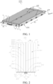
FIG. 1 is a three-dimensional diagram of a battery pack according to an embodiment of the present disclosure. -
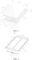
FIG. 2 is a cross-sectional view of a tray according to an embodiment of the present disclosure. -
FIG. 3 is an exploded view of a bottom plate according to an embodiment of the present disclosure. -
FIG. 4 is an exploded view of a tray according to an embodiment of the present disclosure. -
FIG. 5 is a partial schematic view of a tray according to an embodiment of the present disclosure. -
FIG. 6 is a partially enlarged view of part A inFIG. 4 . -
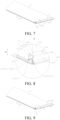
FIG. 7 is a cross-sectional view of a tray at a position according to an embodiment of the present disclosure. -
FIG. 8 is a partially enlarged view of part B inFIG. 7 . -
FIG. 9 is a cross-sectional view of a tray at another position according to an embodiment of the present disclosure. -
FIG. 10 is a partially enlarged view of part C inFIG. 9 .and -
FIG. 11 is a schematic structural diagram of a bottom plate according to another embodiment of the present disclosure. - List of reference numerals:
- 1000 battery pack;
- 100 battery assembly; 1a battery unit; 1 cell;
- 200 tray; 2a temperature adjustment unit; 2b preset unit;
- 2 bottom plate; 20 bottom plate flow channel;
- 201 temperature adjustment flow channel; 2010 outlet end;
- 202 confluence flow channel; 2020 inlet end;
- 203 communicating flow channel;
- 21 first bottom plate; 211 liquid inlet; 212 liquid outlet; 213 communicating liquid port;
- 22 second bottom plate;
- 23 first end portion; 24 second end portion;
- 3 frame; 30 accommodating cavity;
- 31 support beam; 311 sink; 312 first connecting tube accommodating groove;
- 3121 second accommodating groove; 3122 third accommodating groove;
- 32 first side beam; 321 first accommodating groove;
- 33 mounting seat; 331 second connecting tube accommodating groove;
- 3311 fourth accommodating groove; 3312 fifth accommodating groove;
- 4 adapter piece; 40 joining flow channel; 401 first flow channel; 402 second flow channel;
- 41 first connecting portion; 410 bottom plate connection port; 4101 first connection port; 4102 second connection port;
- 42 second connecting portion; 420 connecting tube connection port; 4201 liquid inlet connection port; 4202 liquid outlet connection port;
- 431 top surface; 432 bottom surface; 433 inner side surface; 434 outer side surface;
- 44 partition groove;
- 5 external connecting tube; 501 inner end; 502 outer end; 51 liquid inlet pipe; 52 liquid outlet pipe;
- 6 welded connecting tube; 61 first connecting tube; 62 second connecting tube.
- Embodiments of the present disclosure are described in detail below, and examples of the embodiments are shown in accompanying drawings, where the same or similar elements or the elements having the same or similar functions are denoted by the same or similar reference numerals throughout the description. The embodiments described below with reference to the accompanying drawings are exemplary, and provided merely for explaining the present disclosure, and should not be construed as a limitation on the present disclosure.
- Various embodiments or examples are provided in the disclosure below for implementing various structures of the present disclosure. To simplify the present disclosure, components and configurations of particular examples are described below. However, they are merely exemplary and not intended to limit the present disclosure. In addition, the present disclosure may repeat reference numerals and/or letters in the various examples. This repetition is for the purpose of simplicity and clarity and does not in itself dictate a relationship between the various embodiments and/or configurations discussed. Moreover, examples of various specific processes and materials are provided in the present disclosure; however, those ordinarily skilled in the art will recognize the applicability of other processes and/or the use of other materials.
- A
battery pack 1000 according to some embodiments of the present disclosure is described below with reference to accompanying drawings. - As shown in
FIG. 1 , thebattery pack 1000 according to an embodiment of the present disclosure includes abattery assembly 100 and atray 200. Thebattery assembly 100 includes at least onebattery unit 1a. Thebattery unit 1a includes multiple cells 1, where the length direction of each cell 1 is a first direction F1, and the multiple cells 1 are arranged in a second direction F2; and the second direction F2 intersects the first direction F1. In some embodiments, the thickness direction of the cell 1 is the second direction F2. Referring toFIG. 2 , thetray 200 includes at least onetemperature adjustment unit 2a, and thetemperature adjustment unit 2a is configured to adjust the temperature of thebattery unit 1a. - It should be noted that "adjust the temperature" as described herein may include increasing and decreasing the temperature. For ease of description, the present disclosure is described in connection with an example where the temperature is decreased. In this case, the temperature adjusting fluid is a cooling liquid. Moreover, it should be noted that the number of the
temperature adjustment unit 2a can be set as desired by the number of thebattery unit 1a required to be cooled actually. For example, in some specific examples, the number of thetemperature adjustment unit 2a is equal to the number of thebattery unit 1a, to arrange them in one-to-one correspondence. However, the present disclosure is not limited thereto. In some other examples, the number of thetemperature adjustment unit 2a may be greater than or less than the number of thebattery unit 1a, no further description is given here. - Referring to
FIG. 2 , thetemperature adjustment unit 2a includes abottom plate 2 and a temperatureadjustment flow channel 201 and aconfluence flow channel 202 formed on thebottom plate 2. The temperatureadjustment flow channel 201 and thebattery unit 1a are arranged opposite to each other in a vertical direction (as shown inFIG. 1 ) (that is, the temperatureadjustment flow channel 201 is located right below thebattery unit 1a) to exchange heat with the cells 1. Theconfluence flow channel 202 is arranged to stagger from thebattery unit 1a in the vertical direction (that is, not opposite to each other in the vertical direction, that is, theconfluence flow channel 202 is located obliquely below thebattery unit 1a) to prevent heat exchange with the cells 1. - As shown in
FIG. 2 , both the temperatureadjustment flow channel 201 and theconfluence flow channel 202 extend in the first direction F1, and the temperatureadjustment flow channel 201 and theconfluence flow channel 202 are arranged in the second direction F2. In the first direction F1, one end of the temperatureadjustment flow channel 201 is anoutlet end 2010, one end of theconfluence flow channel 202 close to theoutlet end 2010 is aninlet end 2020, and theoutlet end 2010 of the temperatureadjustment flow channel 201 communicates with theinlet end 2020 of theconfluence flow channel 202. - In this way, the cooling liquid can flow into the temperature
adjustment flow channel 201, then flow forward through the temperatureadjustment flow channel 201 along the first direction F1 toward theoutlet end 2010 of the temperatureadjustment flow channel 201, next flow from theoutlet end 2010 of the temperatureadjustment flow channel 201 to theinlet end 2020 of theconfluence flow channel 202, subsequently flow reversely through theconfluence flow channel 202 along the first direction F1, and flow out of theconfluence flow channel 202. When the cooling liquid flows through the temperatureadjustment flow channel 201, it can cool the cell 1 arranged opposite to the temperatureadjustment flow channel 201 in the vertical direction. During the cooling process of the cell 1, the cooling liquid exchanges heat with the hot cell 1. The temperature of the cooling liquid after heat exchange is high, and the high-temperature cooling liquid flows out of the temperatureadjustment flow channel 201 into theconfluence flow channel 202. During the process of flowing through theconfluence flow channel 202, theconfluence flow channel 202 will not heat the cell 1, since it is arranged to stagger from the cell 1 in the vertical direction, so as to ensure the reliability of the cooling effect on the cell 1. - Briefly, Because the
confluence flow channel 202 is arranged to stagger from thebattery unit 1a in the vertical direction, the cell 1 is not arranged above theconfluence flow channel 202. It can be understood that the temperature of the cooling liquid is low before heat exchange, and the low-temperature cooling liquid flows into the temperatureadjustment flow channel 201; and the temperature of the cooling liquid is high after heat exchange, and the high-temperature cooling liquid flows into theconfluence flow channel 202. Therefore, only the temperatureadjustment flow channel 201 serves to cool the cell 1, and theconfluence flow channel 202 only serves to direct the cooling liquid out of thetemperature adjustment unit 2a without heat exchange with the cell 1, so as to ensure the cooling effect on the cell 1. - Moreover, since the
outlet end 2010 of the temperatureadjustment flow channel 201 and theinlet end 2020 of theconfluence flow channel 202 are located at the same end and communicate with each other in the first direction F1, the cooling liquid can flow forward into the temperatureadjustment flow channel 201 along the first direction F1, and then flow reversely out of theconfluence flow channel 202 along the first direction F1. Therefore, an inlet end of the temperatureadjustment flow channel 201 may be located at the same end with an outlet end of theconfluence flow channel 202, so that the liquid inlet and liquid outlet of thetemperature adjustment unit 2a are located at the same end. Compared with a situation where the liquid inlet and liquid outlet are respectively located at different ends of thetemperature adjustment unit 2a, the location of the liquid inlet and liquid outlet of the cooling liquid at the same end of thetemperature adjustment unit 2a reduces the size of thetemperature adjustment unit 2a in the first direction F1. Accordingly, the size of thebottom plate 2 in the first direction F1 is reduced, and thus the size of thetray 200 in the first direction F1 is reduced. Moreover, the connection to an external device is facilitated. - Any one of the temperature
adjustment flow channels 201 exchanges heat with at least one of the cells 1 arranged in the second direction F2. For example, one cell 1 arranged in the second direction F2 is only cooled by one temperatureadjustment flow channel 201 arranged in the second direction F2; or the same cell 1 arranged in the second direction F2 is cooled by two or more temperatureadjustment flow channels 201 arranged in the second direction F2; or two or more cells 1 arranged in the second direction F2 is cooled by the same temperatureadjustment flow channel 201 arranged in the second direction F2. - Any one of the temperature
adjustment flow channels 201 exchanges heat with at most one cell 1 arranged in the first direction F1. For example, one cell 1 arranged in the first direction F1 is only cooled by one temperatureadjustment flow channel 201 arranged in the first direction F1; or the same cell 1 arranged in the first direction F1 is cooled by two or more temperatureadjustment flow channels 201 arranged in the first direction F1. However, two or more cells 1 arranged in the first direction F1 cannot be cooled by the same temperatureadjustment flow channel 201 arranged in the first direction F1. - It should be noted that in the flow direction of the cooling liquid, the upstream cooling liquid has a low temperature and thus a good cooling effect, and the downstream cooling liquid has a high temperature and thus a poor cooling effect. Therefore, by the fact that any one of the temperature
adjustment flow channel 201 is arranged to exchange heat with at most one cell 1 arranged in the first direction F1, the cooling liquid after heat exchange with one cell 1 is avoided to further flow to exchange heat with a next cell 1. This avoids the problem of inconsistent heat dissipation effects on two cells 1 due to the inconsistent temperatures of the cooling liquid, and allows each cell 1 to have a good heat dissipation consistency. - A tray bottom plate in related art that generally has a serpentine flow channel and a liquid inlet and outlet of the cooling liquid located at a head and tail end of the serpentine flow channel. The temperature of a head flow channel section near the liquid inlet is low, leading to a good cooling effect on cells at a corresponding position; and the temperature of a tail flow channel section near the liquid outlet is high, causing a poor cooling effect on cells at a corresponding position. Therefore, the overall cooling uniformity of the battery pack is poor, and the flow resistance is high. Moreover, the liquid inlet and outlet of the cooling liquid in the tray bottom plate are respectively located at two ends of the bottom plate in the length direction, causing a large size of tray bottom plate in the length direction.
- According to the
battery pack 1000 in accordance with the embodiment of the present disclosure, because theconfluence flow channel 202 is arranged to stagger from thebattery unit 1a in the vertical direction, it does not exchange heat with the cell 1. Only the temperatureadjustment flow channel 201 in which the low-temperature cooling liquid flows serves to cool the cell 1, and theconfluence flow channel 202 in which the high-temperature cooling liquid flows serves to direct the cooling liquid out of thetemperature adjustment unit 2a without cooling the cell 1. Moreover, any one of the temperatureadjustment flow channels 201 exchanges heat with at most one cell 1 arranged in the first direction F 1. Therefore, the cooling consistency of multiple cells 1 is good, and the overall heat dissipation and cooling effect are good. - Furthermore, the inlet end of the temperature
adjustment flow channel 201 is located at the same end of thetemperature adjustment unit 2a in the first direction with the outlet end of theconfluence flow channel 202, so that the liquid inlet and liquid outlet of thetemperature adjustment unit 2a are located at the same end. That is, the liquid inlet and liquid outlet of the cooling liquid are located at the same end of thetemperature adjustment unit 2a to reduce the size of thetemperature adjustment unit 2a in the first direction F1. - In some embodiments of the present disclosure, as shown in
FIG. 2 , thetemperature adjustment unit 2a further includes: a communicatingflow channel 203 formed on thebottom plate 2, aliquid inlet 211 and aliquid outlet 212. Theliquid inlet 211 communicates with the temperatureadjustment flow channel 201, theliquid outlet 212 communicates with theconfluence flow channel 202, and the communicatingflow channel 203 is located at the same side of the temperatureadjustment flow channel 201 and theconfluence flow channel 202 in the first direction F1 and adjacent to theoutlet end 2010 of the temperatureadjustment flow channel 201 and theinlet end 2020 of theconfluence flow channel 202, and brings theoutlet end 2010 of the temperatureadjustment flow channel 201 into communication with theinlet end 2020 of theconfluence flow channel 202. Theliquid inlet 211 and theliquid outlet 212 are both located at the side of the temperatureadjustment flow channel 201 and theconfluence flow channel 202 in the first direction F1 away from the communicatingflow channel 203. Namely, the cooling liquid can flow via theliquid inlet 211 into the temperatureadjustment flow channel 201, and flow out of theconfluence flow channel 202 via theliquid outlet 212; and the cooling liquid flowing out from theoutlet end 2010 of the temperatureadjustment flow channel 201 can flow through the communicatingflow channel 203 into theinlet end 2020 of theconfluence flow channel 202. - Therefore, the entry and exit of the cooling liquid and the flowing between the temperature
adjustment flow channel 201 and theconfluence flow channel 202 can be realized simply and effectively. The liquid inlet and liquid outlet of thetemperature adjustment unit 2a are reliably ensured to be located at the same end, to reduce the size of thetemperature adjustment unit 2a in the first direction F1. - In some embodiments of the present disclosure, referring to
FIG. 2 andFIG. 3 , two ends of thebottom plate 2 in the first direction F1 are respectively afirst end portion 23 and asecond end portion 24, where theliquid inlet 211 and theliquid outlet 212 are both located at thefirst end portion 23, and the communicatingflow channel 203 is located at thesecond end portion 24. Therefore, the cooling liquid can enter thebottom plate 2 via theliquid inlet 211, then flow forward through the entirebottom plate 2 along the first direction F1 into the communicatingflow channel 203, then flow from the communicatingflow channel 203 into and flow reversely through theconfluence flow channel 202 along the first direction F1, and flow out of theliquid outlet 212. - Therefore, the flow path of the cooling liquid can make full use of the
bottom plate 2, and run through the area where the cells 1 are placed as much as possible, to well cool the cell 1, which is conducive to the cooling consistency of the cells 1. For example, when thetray 200 includes only onetemperature adjustment unit 2a, theliquid inlet 211 and theliquid outlet 212 are both located at the same side of thetray 200 in the first direction F1, and the communicatingflow channel 203 is located at the other end oftray 200 in the first direction F1. - However, the present disclosure is not limited thereto. In other embodiments of the present disclosure, the
liquid inlet 211, theliquid outlet 212 and the communicatingflow channel 203 may not be located at two end portions of thebottom plate 2, for example, they are arranged in a middle portion of thebottom plate 2. Furthermore, it should be noted that when thetray 200 includes multipletemperature adjustment units 2a, thebottom plates 2 of two adjacenttemperature adjustment units 2a may have a one-piece structure (i.e., different portions of one bottom plate), or separate structures (that is, two separate bottom plates). - As shown, according to some embodiments of the present disclosure, the
bottom plate 2 includes afirst bottom plate 21 and asecond bottom plate 22 arranged opposite to each other in a thickness direction F3 of thebottom plate 2, where the temperatureadjustment flow channel 201 and theconfluence flow channel 202 are defined between thefirst bottom plate 21 and thesecond bottom plate 22, and theliquid inlet 211 and theliquid outlet 212 are formed to penetrate thefirst bottom plate 21. Therefore, thebottom plate 2 is arranged to include thefirst bottom plate 21 and thesecond bottom plate 22, to facilitate the construction of the temperatureadjustment flow channel 201 and theconfluence flow channel 202. Theliquid inlet 211 is formed to penetrate thefirst bottom plate 21, to facilitate the flow-in of the cooling liquid; and the diameter of theliquid inlet 211 is not affected by the thickness of thebottom plate 2, that is, the diameter of theliquid inlet 211 may be greater than the thickness of thebottom plate 2, to reduce the flow resistance. Theliquid outlet 212 is formed to penetrate thefirst bottom plate 21, to facilitate the flow-out of the cooling liquid; and the diameter of theliquid outlet 212 is not affected by the thickness of thebottom plate 2, that is, the diameter of theliquid outlet 212 may be greater than the thickness of thebottom plate 2, to reduce the flow resistance. - In some embodiments, the
first bottom plate 21 and thesecond bottom plate 22 may be separate structures, or a one-piece structure. In the case of separate structures, thefirst bottom plate 21 and thesecond bottom plate 22 are fabricated separately. In the case of a one-piece structure, the temperatureadjustment flow channel 201 and theconfluence flow channel 202 may be extrusion formed. - In some embodiments of the present disclosure, as shown in
FIG. 2 andFIG. 3 , at least onetemperature adjustment unit 2a is apreset unit 2b, where thepreset unit 2b includes multiple temperatureadjustment flow channels 201 and oneconfluence flow channel 202, and theoutlet end 2010 of each temperatureadjustment flow channel 201 communicates with theinlet end 2020 of theconfluence flow channel 202. Therefore, since the temperatureadjustment flow channels 201 serve to cool the cells 1, the multiple temperatureadjustment flow channel 201 can increase the area that the cooling liquid flows through and the flow rate, to quickly and well cool the cells 1. In addition, oneconfluence flow channel 202 is arranged to flow the cooling liquid after heat exchange out of thetemperature adjustment unit 2a, thereby reducing the space occupied by theconfluence flow channel 202, increasing the cooling area as much as possible, and further improving the cooling efficiency of the cell 1. - Moreover, since the multiple temperature
adjustment flow channels 201 and theconfluence flow channel 202 extend in the first direction F1, the length of each temperatureadjustment flow channel 201 is short compared with the serpentine flow channel. Therefore, the temperature difference between the liquid inlet and outlet ends of each temperatureadjustment flow channel 201 is small, so that the overall temperature of each temperatureadjustment flow channel 201 is uniform and low. This improves the cooling consistency of the cells 1, and reduces the flow resistance of the cooling liquid, to save the energy consumption. - Referring to
FIG. 2 andFIG. 3 , according to some embodiments of the present disclosure, all of the temperatureadjustment flow channels 201 in thepreset unit 2b are located at the same side of theconfluence flow channel 202 in the second direction F2. Since the temperatureadjustment flow channels 201 serve to cool the cells 1 and theconfluence flow channel 202 does not serve to cool the cells 1, the multiple temperatureadjustment flow channels 201 are all located at the same side of theconfluence flow channel 202 in the second direction F2, to promote the arrangement of the multiple cells 1, and well cool the multiple cells 1. - In some embodiments of the present disclosure, referring to
FIG. 2 andFIG. 3 , thetray 200 includes twopreset units 2b, and the twopreset units 2b are arranged at an interval in the second direction F2. Further, the twopreset units 2b are distributed symmetrically. Therefore, the symmetric distribution of the twopreset units 2b facilitates the arrangement of thepreset units 2b to make the structure of thebottom plate 2 become more compact, and allow twoconfluence flow channels 202 in the twopreset units 2b to get closer or allow all the temperatureadjustment flow channels 201 in the twopreset units 2b to get closer. This facilitates the arrangement of the multiple cells 1, and alleviates the problem of heat transfer between theconfluence flow channel 202 in onepreset unit 2b and the temperatureadjustment flow channel 201 in anotherpreset unit 2b. - Referring to
FIG. 2 to FIG. 4 , according to some embodiments of the present disclosure, thetray 200 further includes aframe 3, where theframe 3 is connected to thebottom plate 2 and defines anaccommodating cavity 30 with thebottom plate 2. Theframe 3 includes asupport beam 31 extending in the first direction F1, where thesupport beam 31 is located above a portion between thepreset units 2b, and theconfluence flow channel 202 in eachpreset unit 2b is arranged opposite to thesupport beam 31 in the vertical direction. Therefore, thesupport beam 31 can enhance the structural strength of theframe 3. Moreover, the arrangement of thesupport beam 31 right above theconfluence flow channel 202 can more effectively ensure that theconfluence flow channel 202 and the battery cell 1 are staggered in the vertical direction, to avoid the heat exchange of theconfluence flow channel 202 with cell 1. - In specific examples shown in
FIG. 2 to FIG. 4 , theconfluence flow channel 202 in eachpreset unit 2b is located at one side of the temperatureadjustment flow channels 201 in the correspondingpreset unit 2b close to the otherpreset unit 2b. This facilitates the arrangement of cells 1 and conforms to the structural layout of theframe 3. For example, to ensure the reliability of theframe 3, thesupport beam 31 can be generally arranged in the middle of theframe 3, and thesupport beam 31 rightly faces theconfluence flow channel 202 of thepreset unit 2b, so that the structural reliability of theframe 3 can be ensured without affecting the cooling of the cell 1. - In some embodiments of the present disclosure, referring to
FIG. 2 andFIG. 3 , thetemperature adjustment unit 2a includes N temperatureadjustment flow channel 201 and Mconfluence flow channels 202, where M is an integer greater than or equal to 1, and, N is an integer greater than or equal to 1; and the sum of width of the N temperatureadjustment flow channels 201 in eachtemperature adjustment unit 2a is greater than the sum of width of the Mconfluence flow channels 202. Therefore, the area where the cooling liquid flows through in the temperatureadjustment flow channel 201 is large, to effectively cool the cell 1. - In a specific example shown in
FIG. 2 , the width of the temperatureadjustment flow channel 201 is a mean width in the second direction F2. The temperatureadjustment flow channel 201 may be an equal-width flow channel or an unequal-width flow channel. Similarly, the width of theconfluence flow channel 202 is a mean width in the second direction F2. Theconfluence flow channel 202 may be an equal-width flow channel or an unequal-width flow channel. - As shown in
FIG. 2 , according to some embodiments of the present disclosure, at least onetemperature adjustment unit 2a includes: anadapter piece 4 and an external connectingtube 5. Theadapter piece 4 has afirst flow channel 401 and asecond flow channel 402 separated from each other therein, where thefirst flow channel 401 communicates with the temperatureadjustment flow channel 201, and thesecond flow channel 402 communicates with theconfluence flow channel 202. The external connectingtube 5 includes aliquid inlet pipe 51 and aliquid outlet pipe 52, where theliquid inlet pipe 51 is connected to theadapter piece 4 and communicates with thefirst flow channel 401, and theliquid outlet pipe 52 is connected to theadapter piece 4 and communicates with thesecond flow channel 402. - As such, the cooling liquid can enter the
first flow channel 401 from theliquid inlet pipe 51, and flow through thefirst flow channel 401 to the temperatureadjustment flow channel 201. The cell 1 can be arranged opposite to the temperatureadjustment flow channel 201, so the cell 1 is cooled when the cooling liquid flows through the temperatureadjustment flow channel 201. During the cooling process of the cell 1, hot cell 1 exchanges heat with the cooling liquid. Therefore, the temperature of the cooling liquid at the end of the temperatureadjustment flow channel 201 away from theadapter piece 4 in the first direction F1 is high. The high-temperature cooling liquid flows through theconfluence flow channel 202 to thesecond flow channel 402. The cooling liquid flowing through thesecond flow channel 402 does not exchange heat with the cell 1, and can flow out of theliquid outlet pipe 52 after passing through thesecond flow channel 402. - Therefore, by arranging the
adapter piece 4, only one set ofliquid inlet pipe 51 andliquid outlet pipe 52 is required to be provided even when the number of the temperatureadjustment flow channel 201 and /or theconfluence flow channel 202 is greater than 1, thus reducing the number of theliquid inlet pipe 51 and theliquid outlet pipe 52, and simplifying the structural complexity. However, the present disclosure is not limited thereto. Multiple sets ofliquid inlet pipes 51 andliquid outlet pipes 52 may also be provided. - In the related art, a tray bottom plate of a battery pack generally has a serpentine flow channel, and liquid inlet and outlet pipes are located at a head and tail end of the serpentine flow channel and at two sides of the tray bottom plate in the length direction, causing a large size of the tray bottom plate in the length direction. Moreover, the liquid inlet and outlet pipes are directly inserted into the head and tail end of the serpentine flow channel along a direction parallel to the bottom plate. With a given thickness of the tray bottom plate, the diameter of the liquid inlet and outlet pipes is limited by the thickness of the tray bottom plate, and liquid inlet and outlet pipes with a diameter smaller than the thickness of the tray bottom plate have to be used, causing a large flow resistance to the cooling liquid.
- In the
battery pack 1000 according to the present disclosure, since theliquid inlet pipe 51 is connected to the temperatureadjustment flow channel 201 by theadapter piece 4 and theliquid outlet pipe 52 is connected to theconfluence flow channel 202 by theadapter piece 4, theliquid inlet pipe 51 and theliquid outlet pipe 52 can be located at the same side of thetemperature adjustment unit 2a in the first direction F1, giving rise to a small size of thetray 200 in the first direction F1. Moreover, by connecting theliquid inlet pipe 51 and theliquid outlet pipe 52 to theadapter piece 4, the diameter of theliquid inlet pipe 51 and theliquid outlet pipe 52 is not affected by the thickness of thebottom plate 2. With a small thickness of thebottom plate 2, aliquid inlet pipe 51 and aliquid outlet pipe 52 having a large diameter can be used, to reduce the flow resistance of the cooling liquid. - As shown in
FIG. 6 , in some embodiments of the present disclosure, theadapter piece 4 can be a one-piece structure and theadapter piece 4 has apartition groove 44. A partition can be placed in thepartition groove 44 to define thefirst flow channel 401 and thesecond flow channel 402 which are separated from each other in theadapter piece 4. However, the present disclosure is not limited thereto. In other embodiments of the present disclosure, theadapter piece 4 may be directly formed with a partition structure therein. Alternatively, theadapter piece 4 is formed of multiple separate structures, where at least one separate structure defines thefirst flow channel 401, and at least one separate structure defines thesecond flow channel 402, etc. - Furthermore, one or
multiple adapter piece 4 can be provided. When thetray 200 includes multipletemperature adjustment units 2a (as shown inFIG. 2 andFIG. 6 ), theadapter piece 4 of two adjacenttemperature adjustment units 2a can be formed of separate structures, or theadapter piece 4 of two adjacenttemperature adjustment units 2a can also be a one-piece structure. For example, theadapter piece 4 of a one-piece structure can be divided into multiple flow channels by a structure such as a partition, to work for correspondingtemperature adjustment units 2a. Twotemperature adjustment units 2a may share oneadapter piece 4 and onesecond flow channel 402. - The
tray 200 for abattery pack 1000 according to some embodiments of the present disclosure will be described in connection with the accompanying drawings. - As shown in
FIG. 4 , thetray 200 can include abottom plate 2, aframe 3, an external connectingtube 5 andadapter piece 4. Theframe 3 is connected to thebottom plate 2 and defines anaccommodating cavity 30 with thebottom plate 2. Theaccommodating cavity 30 is configured to accommodate thebattery assembly 100, and theframe 3 includes afirst side beam 32. Referring toFIG. 5 and FIG. 6 , aninner end 501 of the external connectingtube 5 extends into thefirst side beam 32, a firstaccommodating groove 321 is formed on thefirst side beam 32, theadapter piece 4 is arranged at a side of thebottom plate 2 in a thickness direction, and theadapter piece 4 is accommodated in the firstaccommodating groove 321. Therefore, the firstaccommodating groove 321 provides a mounting space for theadapter piece 4, so thefirst side beam 32 can protect theadapter piece 4, to reduce the damage of theadapter piece 4 from dust and corrosion. Here, it should be noted that there is on limitation on the position where thefirst side beam 32 is arranged. For example, thefirst side beam 32 can extend in a length direction of thetray 200 and arranged close to a side edge of thetray 200 in a width direction, or extend in the width direction of thetray 200 and arranged close to a side edge of thetray 200 in the length direction. - Referring to
FIG. 2 , thebottom plate 2 has a bottomplate flow channel 20 therein, and theadapter piece 4 has a joiningflow channel 40 therein. Referring toFIG. 6 andFIG. 8 , theadapter piece 4 includes a first connectingportion 41 and a second connectingportion 42, where the first connectingportion 41 is connected to thebottom plate 2 to bring the joiningflow channel 40 into communication with the bottomplate flow channel 20, the second connectingportion 42 is connected to theinner end 501 of the external connectingtube 5 to bring the joiningflow channel 40 into communication with the external connectingtube 5, and the first connectingportion 41 and the second connectingportion 42 are buried in thefirst side beam 32. Therefore, thefirst side beam 32 can protect the first connectingportion 41 and the second connectingportion 42, that is, the connection portion of theadapter piece 4 to thebottom plate 2, and the connection portion of theadapter piece 4 and the external connectingtube 5, to improve the mounting reliability of theadapter piece 4 and reduce the risk of leakage of the cooling liquid at the connection portion. - It should be noted that the cooling liquid can flow from the external connecting
tube 5 into the joiningflow channel 40, and flow through the joiningflow channel 40 to the bottomplate flow channel 20. Then, the cooling liquid flows through the bottomplate flow channel 20, passes through the joiningflow channel 40 and flows out of the external connectingtube 5. Thebattery assembly 100 can be arranged above the bottomplate flow channel 20, and the cooling liquid can cool thebattery assembly 100 when flows in the bottomplate flow channel 20. - In a specific example, referring to
FIG. 6 , the external connectingtube 5 can include aliquid inlet pipe 51 and aliquid outlet pipe 52, the joiningflow channel 40 includes afirst flow channel 401 and asecond flow channel 402 separated from each other, the bottomplate flow channel 20 includes a temperatureadjustment flow channel 201 and aconfluence flow channel 202, theliquid inlet pipe 51 communicates with thefirst flow channel 401, theliquid outlet pipe 52 communicates with thesecond flow channel 402, thefirst flow channel 401 communicates with theflow channel 201, and thesecond flow channel 402 communicates with theconfluence flow channel 202. The cooling liquid flows through theliquid inlet pipe 51 into thefirst flow channel 401, then flows from thefirst flow channel 401 to the temperatureadjustment flow channel 201 and then to theconfluence flow channel 202 after flowing through the temperatureadjustment flow channel 201, subsequently flows from theconfluence flow channel 202 to thesecond flow channel 402, and then flows out of theliquid outlet pipe 52. In this embodiment, thebattery assembly 100 can be located above the temperatureadjustment flow channel 201, or above the temperatureadjustment flow channel 201 and theconfluence flow channel 202. - The
adapter piece 4 is connected to the external connectingtube 5, such that the external connectingtube 5 is arranged at the same side of thebottom plate 2, giving rise to a small size of thetray 200. Moreover, by arranging theadapter piece 4 at a side of thebottom plate 2 in the thickness direction and connecting the external connectingtube 5 to theadapter piece 4, the diameter of the external connectingtube 5 is allowed not to be affected by the thickness of thebottom plate 2. With a small thickness of thebottom plate 2, an external connectingtube 5 having a large diameter can be used, to reduce the flow resistance of the cooling liquid. For example, the diameter of theliquid inlet pipe 51 and theliquid outlet pipe 52 is allowed not to be affected by the thickness of thebottom plate 2. With a small thickness of thebottom plate 2, aliquid inlet pipe 51 and aliquid outlet pipe 52 having a large diameter can be used, to reduce the flow resistance of the cooling liquid. - In some embodiments of the present disclosure, as shown in
FIG. 5 , theadapter piece 4 is in clearance fit with a groove wall of the firstaccommodating groove 321. Namely, theadapter piece 4 does not contact the groove wall of the firstaccommodating groove 321, to avoid the problem of pressure caused by thefirst side beam 32 to theadapter piece 4, and further protect theadapter piece 4. - In some embodiments of the present disclosure, the first connecting
portion 41 is welded to thebottom plate 2, since the connection by welding is a relatively stable connection. Therefore, the first connectingportion 41 can be simply and reliably connected to thebottom plate 2, to reduce the risk of disconnection of the first connectingportion 41 from thebottom plate 2, and reduce the risk of leakage of the cooling liquid at the first connectingportion 41. - In some embodiments of the present disclosure, the second connecting
portion 42 is welded to theinner end 501 of the external connectingtube 5, since the connection by welding is a relatively stable connection. Therefore, the second connectingportion 42 can be simply and reliably connected to the external connectingtube 5, to reduce the risk of disconnection of the second connectingportion 42 from the external connectingtube 5, and reduce the risk of leakage of the cooling liquid at the second connectingportion 42. - According to some embodiments of the present disclosure, as shown in
FIG. 2 andFIG. 3 , thebottom plate 2 is provided with a communicatingliquid port 213 on a surface at one of the two sides in the thickness direction facing theadapter piece 4. Referring toFIG. 8 , the first connectingportion 41 is constructed as a bottomplate connection port 410, thetray 200 further includes a welded connectingtube 6, one end of the welded connectingtube 6 is inserted into and welded to the communicatingliquid port 213, and the other end of the welded connectingtube 6 is inserted into and welded to the bottomplate connection port 410, so that the first connectingportion 41 is welded to thebottom plate 2. - Therefore, by arranging the communicating
liquid port 213 and the bottomplate connection port 410, the welded connectingtube 6 can be conveniently connected, to bring the bottomplate flow channel 20 into communication with the joiningflow channel 40 by the welded connectingtube 6. Therefore, by directing the cooling liquid by the welded connectingtube 6, the cooling liquid can smoothly flow from the joiningflow channel 40 to the bottomplate flow channel 20. Therefore, the difficulty and complexity of bringing theadapter piece 4 and thebottom plate 2 into communication are reduced the structure is simplified, and the connection of the first connectingportion 41 to thebottom plate 2 by welding is promoted. - Moreover, referring to
FIG. 8 , the diameter of the welded connectingtube 6 can be manufactured according to the diameters of the communicatingliquid port 213 and the bottomplate connection port 410. Since the communicatingliquid port 213 is located on the surface at the side of thebottom plate 2 in the thickness direction facing theadapter piece 4, the port diameter of the communicatingliquid port 213 is not limited by the thickness of thebottom plate 2. Therefore, the communicatingliquid port 213 can be large. The bottomplate connection port 410 is provided on the surface of theadapter piece 4 at the side facing thebottom plate 2 and can also be large without limitation by the thickness of theadapter piece 4, so a welded connectingtube 6 with a larger diameter can be used, to further reduce the flow resistance of the cooling liquid, and save the energy consumption. - Referring to
FIG. 6 , in some embodiments of the present disclosure, the second connectingportion 42 is constructed as a connectingtube connection port 420, and theinner end 501 of the external connectingtube 5 is inserted into and welded to the connectingtube connection port 420, so the second connectingportion 42 is welded to the external connectingtube 5. Therefore, the connectingtube connection port 420 can provide a mounting environment for the external connectingtube 5, and theinner end 501 of the external connectingtube 5 is inserted into and welded to the connectingtube connection port 420, so the second connectingportion 42 can be reliably connected to the external connectingtube 5, to reduce the risk of disconnection of the second connectingportion 42 from the external connectingtube 5. - According to some embodiments of the present disclosure, as shown in
FIG. 5 , theouter end 502 of the external connectingtube 5 is exposed at the side of thefirst side beam 32 away from theaccommodating cavity 30. As such, the connection of the external connectingtube 5 to other cooling liquid accommodating devices is facilitated, to introduce the cooling liquid into thetray 200 or discharge the cooling liquid from thetray 200. Moreover, the second connectingportion 42 is located at the side of theadapter piece 4 away from theaccommodating cavity 30, to facilitate the connection of the second connectingportion 42 to the external connectingtube 5. - For example, in a specific example shown in
FIG. 8 , theadapter piece 4 can include abottom surface 432, atop surface 431, an inner side surface 433 and anouter side surface 434. Thebottom surface 432 is arranged opposite to thetop surface 431; and in the thickness direction F3 of thebottom plate 2, thebottom surface 432 is spaced from thetop surface 431, and thetop surface 431 is located at the side of thebottom surface 432 away from thebottom plate 2. The inner side surface 433 and theouter side surface 434 are connected between thetop surface 431 and thebottom surface 432, and the inner side surface 433 is arranged closer to the central point of thebottom plate 2 than theouter side surface 434. - Referring to
FIG. 6 , the connectingtube connection port 420 is formed on theouter side surface 434 of theadapter piece 4. It can be understood that thebottom surface 432, thetop surface 431, the inner side surface 433 and theouter side surface 434 can define the joiningflow channel 40, and the connectingtube connection port 420 is formed on theouter side surface 434 of theadapter piece 4 so as to locate at the side of theadapter piece 4 away from theaccommodating cavity 30. Therefore, the external connectingtube 5 can be inserted into theouter side surface 434 from the outside to the inside, to bring the external connectingtube 5 into communication with the joiningflow channel 40, and expose theouter end 502 of the external connectingtube 5 at the side of thefirst side beam 32 away from theaccommodating cavity 30. - As shown in
FIG. 5 , in some embodiments of the present disclosure, the central axis L2 of the external connectingtube 5 is perpendicular to the length direction F4 of theadapter piece 4, and perpendicular to the thickness direction F3 of thebottom plate 2. Referring toFIG. 2 , the length direction F4 of theadapter piece 4 is the second direction F2, and the extending direction of the central axis L2 of the external connectingtube 5 is the first direction F1. This facilitates the positioning, mounting and arrangement of the external connectingtube 5. - In a possible implementation, referring to
FIG. 6 , the external connectingtube 5 can include aliquid inlet pipe 51 and aliquid outlet pipe 52, Therefore, the positioning, mounting and arrangement of theliquid inlet pipe 51 and theliquid outlet pipe 52 are also facilitated. As shown inFIG. 2 , the arrangement of multiple bottomplate connection ports 410 on theadapter piece 4 is also facilitated. The bottomplate connection ports 410 can include afirst connection port 4101 and asecond connection port 4102, and the communicatingliquid port 213 can include aliquid inlet 211 and aliquid outlet 212. Theliquid inlet 211 is connected to thefirst connection port 4101 in one-to-one correspondence, and theliquid outlet 212 is connected to thesecond connection port 4102 in one-to-one correspondence. - According to some embodiments of the present disclosure, referring to
FIG. 2 andFIG. 3 , the surface of thebottom plate 2 at one of two sides in the thickness direction facing theadapter piece 4 is provided with aliquid inlet 211 and aliquid outlet 212. Theliquid inlet 211 communicates with the temperatureadjustment flow channel 201, and theliquid outlet 212 communicates with theconfluence flow channel 202. The surface of theadapter piece 4 at the side facing thebottom plate 2 is provided with afirst connection port 4101 and asecond connection port 4102. Thefirst connection port 4101 communicates with theliquid inlet 211, and thesecond connection port 4102 communicates with theliquid outlet 212. Referring toFIG. 8 andFIG. 10 , the welded connectingtube 6 can include a first connectingtube 61 and a second connectingtube 62. One end of the first connectingtube 61 is inserted into and fitted to theliquid inlet 211, and the other end of the first connectingtube 61 is inserted into and fitted to thefirst connection port 4101. One end of the second connectingtube 62 is inserted into and fitted to theliquid outlet 212, and the other end of the second connectingtube 62 is inserted into and fitted to thesecond connection port 4102. - As such, by arranging the
liquid inlet 211 and thefirst connection port 4101 as described above, the mounting of the first connectingtube 61 is facilitated, to bring the temperatureadjustment flow channel 201 into communication with thefirst flow channel 401 by the first connectingtube 61. Therefore, by directing the cooling liquid by the first connectingtube 61, the cooling liquid is allowed to flow smoothly from thefirst flow channel 401 to the temperatureadjustment flow channel 201. Similarly, by arranging theliquid outlet 212 and thesecond connection port 4102 as described above, the mounting of the second connectingtube 62 is facilitated, to bring theconfluence flow channel 202 into communication with thesecond flow channel 402 by the second connectingtube 62. Therefore, by directing the cooling liquid by the second connectingtube 62, the cooling liquid is allowed to flow smoothly from theconfluence flow channel 202 to thesecond flow channel 402. Therefore, the difficulty and complexity of bringing theadapter piece 4 and thebottom plate 2 into communication are reduced and the structure is simplified. - Moreover, the diameter of the first connecting
tube 61 can be manufactured according to the diameter of theliquid inlet 211 and thefirst connection port 4101. Since theliquid inlet 211 is located on the surface of thebottom plate 2 at one of two sides in the thickness direction facing theadapter piece 4, the diameter of theliquid inlet 211 is not limited by the thickness of thebottom plate 2. Therefore, theliquid inlet 211 can be large. Thefirst connection port 4101 is provided on the surface of theadapter piece 4 at the side facing thebottom plate 2, and can also be large without limitation by the thickness of theadapter piece 4. Similarly, the diameter of the second connectingtube 62 can be manufactured according to the diameter of the diameter of theliquid outlet 212 and thesecond connection port 4102. Since theliquid outlet 212 is located on the surface at the side of thebottom plate 2 in the thickness direction facing theadapter piece 4, the diameter of theliquid outlet 212 is not limited by the thickness of thebottom plate 2. Therefore, theliquid outlet 212 can be large. Thesecond connection port 4102 is provided on the surface of theadapter piece 4 at the side facing thebottom plate 2, and can also be large without limitation by the thickness of theadapter piece 4. Therefore, a first connectingtube 61 and a second connectingtube 62 with a larger diameter can be used, to further reduce the flow resistance of the cooling liquid, and save the energy consumption. - As shown in
FIG. 6 , in some embodiments of the present disclosure, the surface of theadapter piece 4 at the side away from theaccommodating cavity 30 is provided with a connectingtube connection port 420, and the connectingtube connection port 420 includes a liquidinlet connection port 4201 and a liquidoutlet connection port 4202. The liquidinlet connection port 4201 communicates with thefirst flow channel 401, and the liquidoutlet connection port 4202 communicates with thesecond flow channel 402. The outlet end of theliquid inlet pipe 51 is connected to the liquidinlet connection port 4201, to introduce the cooling liquid into thefirst flow channel 401; and the inlet end of theliquid outlet pipe 52 is connected to the liquidoutlet connection port 4202, to discharge the cooling liquid from thesecond flow channel 402. Therefore, the liquidinlet connection port 4201 can facilitate the connection of theliquid inlet pipe 51, to bring theliquid inlet pipe 51 into communication with thefirst flow channel 401; and the liquidoutlet connection port 4202 can facilitate the connection of theliquid outlet pipe 52, to bring theliquid outlet pipe 52 into communication with thesecond flow channel 402. Moreover, the connection of theliquid inlet pipe 51 and theliquid outlet pipe 52 with an external cooling liquid system is also facilitated. - According to some embodiments of the present disclosure, as shown in
FIG. 6 , asink 311 is further formed on thefirst side beam 32, and thesink 311 communicates with the firstaccommodating groove 321. A first connectingtube accommodating groove 312 communicating with thesink 311 is formed on a bottom wall of thesink 311. Theframe 3 further includes a mountingseat 33, where the mountingseat 33 is embedded in thesink 311 and a second connectingtube accommodating groove 331 is formed on the mountingseat 33. Theinner end 501 of the external connectingtube 5 is received in a space defined by the first connectingtube accommodating groove 312 and the second connectingtube accommodating groove 331. - Therefore, by arranging the mounting
seat 33, the space defined by first connectingtube accommodating groove 312 and the second connectingtube accommodating groove 331 can provide a mounting environment for the external connectingtube 5, and protect the external connectingtube 5. By arranging thesink 311, the mountingseat 33 can be effectively taken in, to improve the structure compactness of thebattery pack 1000. - For example, as shown in
FIG. 6 , the first connectingtube accommodating groove 312 can include a secondaccommodating groove 3121 and a thirdaccommodating groove 3122. The second connectingtube accommodating groove 331 can include a fourthaccommodating groove 3311 and a fifthaccommodating groove 3312. Theinner end 501 of theliquid inlet pipe 51 is received in a space defined by the secondaccommodating groove 3121 and the fourthaccommodating groove 3311 and is connected to theadapter piece 4, and theouter end 502 of theliquid inlet pipe 51 is exposed at the side of thefirst side beam 32 away from theaccommodating cavity 30. Theinner end 501 of theliquid outlet pipe 52 is received in a space defined by the thirdaccommodating groove 3122 and the fifthaccommodating groove 3312 and is connected to theadapter piece 4, and theouter end 502 of theliquid outlet pipe 52 is exposed at the side of thefirst side beam 32 away from theaccommodating cavity 30. - Therefore, the
inner end 501 of theliquid inlet pipe 51 facilitates the connection to theadapter piece 4 and can be protected by thefirst side beam 32; and the exposure of theouter end 502 of theliquid inlet pipe 51 at thefirst side beam 32 facilitates the connection of theliquid inlet pipe 51 to the external cooling liquid system. Theinner end 501 of theliquid outlet pipe 52 facilitates the connection to theadapter piece 4 and can be protected by thefirst side beam 32; and the exposure of theouter end 502 of theliquid outlet pipe 52 at thefirst side beam 32 facilitates the connection of theliquid outlet pipe 52 to the external cooling liquid system. - Referring to
FIG. 2 , in some embodiments of the present disclosure, the bottomplate flow channel 20 includes a temperatureadjustment flow channel 201 and aconfluence flow channel 202, both the temperatureadjustment flow channel 201 and theconfluence flow channel 202 extend in the first direction F1, and the temperatureadjustment flow channel 201 and theconfluence flow channel 202 are arranged in the second direction F2. The second direction F2 intersects the first direction F1. Theadapter piece 4 is located at a side of the bottomplate flow channel 20 in the first direction F1, the joiningflow channel 40 includes afirst flow channel 401 and asecond flow channel 402 separated from each other, thefirst flow channel 401 communicates with the temperatureadjustment flow channel 201, and thesecond flow channel 402 communicates with theconfluence flow channel 202. One end of the temperatureadjustment flow channel 201 away from theadapter piece 4 in the first direction F1 is anoutlet end 2010, and one end of theconfluence flow channel 202 away from theadapter piece 4 in the first direction F1 is aninlet end 2020. Theoutlet end 2010 of the temperatureadjustment flow channel 201 communicates with theinlet end 2020 of theconfluence flow channel 202. The external connectingtube 5 includes aliquid inlet pipe 51 and aliquid outlet pipe 52, where theliquid inlet pipe 51 communicates with thefirst flow channel 401, and theliquid outlet pipe 52 communicates with thesecond flow channel 402. - Specifically, referring to
FIG. 2 , the cooling liquid can enter thefirst flow channel 401 from theliquid inlet pipe 51, and flow through thefirst flow channel 401 to the temperatureadjustment flow channel 201. Thebattery assembly 100 can be arranged opposite to the temperatureadjustment flow channel 201, so thebattery assembly 100 is cooled when the cooling liquid flows through the temperatureadjustment flow channel 201. During the cooling process of thebattery assembly 100,hot battery assembly 100 exchanges heat with the cooling liquid. Therefore, the temperature of the cooling liquid at the end of the temperatureadjustment flow channel 201 away from theadapter piece 4 in the first direction F1 is high. The high-temperature cooling liquid flows through theconfluence flow channel 202 to thesecond flow channel 402, and the cooling liquid in thesecond flow channel 402 flows out of thetray 200 through theliquid outlet pipe 52. - Since the
liquid inlet pipe 51 is connected to the temperatureadjustment flow channel 201 by theadapter piece 4 and theliquid outlet pipe 52 is connected to theconfluence flow channel 202 by theadapter piece 4, theliquid inlet pipe 51 and theliquid outlet pipe 52 can be located at the same side of thebottom plate 2 in the first direction F1, giving rise to a small size of thetray 200 in the first direction F1. Moreover, by arranging theadapter piece 4 at a side of thebottom plate 2 in the thickness direction and connecting theliquid inlet pipe 51 and theliquid outlet pipe 52 to theadapter piece 4, the diameter of theliquid inlet pipe 51 and theliquid outlet pipe 52 is not affected by the thickness of thebottom plate 2. With a small thickness of thebottom plate 2, aliquid inlet pipe 51 and aliquid outlet pipe 52 having a large diameter can be used, to reduce the flow resistance of the cooling liquid. - Furthermore, for a serpentine flow channel in the related art, the temperature of a head flow channel section near the liquid inlet pipe is low, leading to a good cooling effect on the battery assembly at a corresponding position; and the temperature of a tail flow channel section near the liquid outlet pipe is high, causing a poor cooling effect on the battery assembly at a corresponding position. Therefore, the overall cooling uniformity of the battery pack is poor.
- According to the
tray 200 in accordance with the embodiment of the present disclosure, in some embodiments, theconfluence flow channel 202 can be arranged to stagger from thebattery assembly 100 in the vertical direction. That is, they are not rightly opposite to each other in the vertical direction, thereby avoiding the heat exchange of theconfluence flow channel 202 with thebattery assembly 100, and ensuring the cooling effect on thebattery assembly 100. Namely, when theconfluence flow channel 202 is arranged to stagger from the position of thebattery assembly 100, the heat dissipation effect of thebattery assembly 100 can be effectively ensured. Further, when multiple temperatureadjustment flow channels 201 are provided and arranged in the second direction F2, since the length of each temperatureadjustment flow channel 201 is short, and the temperature difference between the liquid inlet and outlet ends of each temperatureadjustment flow channel 201 is small, the overall temperature of each temperatureadjustment flow channel 201 is uniform and low. This improves the cooling consistency of thebattery pack 1000. - Referring to
FIG. 1 and FIG. 2 , in some embodiments of the present disclosure, the first direction F1 is the length direction of thebottom plate 2, the second direction F2 is the width direction of thebottom plate 2, and theadapter piece 4 is provided at an end portion of thebottom plate 2 in the first direction F 1. Therefore, the arrangement of theadapter piece 4 at an end portion of thebottom plate 2 can facilitate the mounting and fixation of theadapter piece 4, and simply and effectively ensure that thebottom plate 2 has a cooling effect in the entire length direction, to ensure the cooling effect of thebottom plate 2 on thebattery assembly 100, simplify the structure of thebottom plate 2, and reduce the influence of theadapter piece 4 on the arrangement of thebattery assembly 100. However, the present disclosure is not limited thereto. In other embodiments of the present disclosure, theadapter piece 4 may also be provided in the middle or at other positions of thebottom plate 2, which will not be further described here. - In the description of the specification, the description with reference to the terms "an embodiment", "some embodiments", "example", "specific example", or "some example" and so on means that specific features, structures, materials or characteristics described in connection with the embodiment or example are embraced in at least one embodiment or example of the present disclosure. In the specification, the schematic expressions of the above terms do not necessarily refer to the same embodiment or example. Moreover, the described specific features, structures, materials or characteristics may be combined in any suitable manners in one or more embodiments. In addition, where there are no contradictions, the various embodiments or examples described in the specification and features of various embodiments or examples can be combined by those skilled in the art.
- Although the embodiments of the present disclosure have been shown and described, a person of ordinary skill in the art should understand that various changes, modifications, replacements and variations may be made to the embodiments without departing from the principles and spirit of the present disclosure, and the scope of the present disclosure is as defined by the appended claims and their equivalents.
Claims (10)
- A battery pack (1000), comprising:a battery assembly (100), wherein the battery assembly (100) comprises at least one battery unit (1a), the battery unit (1a) comprises a plurality of cells (1), the length direction of each cell (1) is a first direction (F1), and the plurality of cells (1) are arranged in a second direction (F2); anda tray (200), wherein the tray (200) comprises at least one temperature adjustment unit (2a), the temperature adjustment unit (2a) comprises a bottom plate (2) and a temperature adjustment flow channel (201) and a confluence flow channel (202) formed on the bottom plate (2), the temperature adjustment flow channel (201) is arranged opposite to the battery unit (1a) in a vertical direction to exchange heat with the cell (1), the confluence flow channel (202) is arranged to stagger from the battery unit (1a) in the vertical direction to prevent heat exchange with the cell (1), the temperature adjustment flow channel (201) and the confluence flow channel (202) both extend in the first direction (F1), and the temperature adjustment flow channel (201) and the confluence flow channel (202) are arranged in the second direction (F2); and in the first direction (F1), one end of the temperature adjustment flow channel (201) is an outlet end (2010), one end of the confluence flow channel (202) close to the outlet end (2010) is an inlet end (2020), the outlet end (2010) of the temperature adjustment flow channel (201) communicates with the inlet end (2020) of the confluence flow channel (202), the second direction (F2) intersects the first direction (F1), any one of the temperature adjustment flow channels (201) exchanges heat with at least one cell (1) arranged in the second direction (F1), and exchanges heat with at most one cell (1) arranged in the first direction (F1).
- The battery pack (1000) according to claim 1, wherein the temperature adjustment unit (2a) further comprises: a communicating flow channel (203), a liquid inlet (211) and liquid outlet (212) formed on the bottom plate (2), wherein the liquid inlet (211) communicates with the temperature adjustment flow channel (201), the liquid outlet (212) communicates with the confluence flow channel (202), the communicating flow channel (203) is located at the same side of the temperature adjustment flow channel (201) and the confluence flow channel (202) in the first direction (F1) and adjacent to the outlet end (2010) of the temperature adjustment flow channel (201) and the inlet end (2020) of the confluence flow channel (202), the communicating flow channel (203) brings the outlet end (2010) of the temperature adjustment flow channel (201) into communication with the inlet end (2020) of the confluence flow channel (202), and the liquid inlet (211) and the liquid outlet (212) are both located at a side of the temperature adjustment flow channel (201) and the confluence flow channel (202) away from the communicating flow channel (203) in the first direction (F1).
- The battery pack (1000) according to claim 2, wherein two ends of the bottom plate (2) in the first direction (F1) are respectively a first end portion (23) and a second end portion (24), the liquid inlet (211) and the liquid outlet (212) are both located at the first end portion (23), and the communicating flow channel (203) is located at the second end portion (24).
- The battery pack (1000) according to claim 2 or 3, wherein the bottom plate (2) comprises a first bottom plate (21) and a second bottom plate (22) arranged opposite to each other in a thickness direction (F3) of the bottom plate (2), the temperature adjustment flow channel (201) and the confluence flow channel (202) are defined between the first bottom plate (21) and the second bottom plate (22), and the liquid inlet (211) and the liquid outlet (212) are formed to penetrate through the first bottom plate (21).
- The battery pack (1000) according to any one of claims 1 to 4, wherein at least one temperature adjustment unit (2a) is a preset unit (2b), the preset unit (2b) comprises a plurality of temperature adjustment flow channels (201) and one confluence flow channel (202), and the outlet end (2010) of each temperature adjustment flow channel (201) communicates with the inlet end (2020) of the confluence flow channel (202).
- The battery pack (1000) according to claim 5, wherein all of the temperature adjustment flow channels (201) in the preset unit (2b) are located at the same side of the confluence flow channel (202) in the second direction (F2).
- The battery pack (1000) according to claim 6, wherein the tray (200) comprises two preset units (2b), and the two preset units (2b) are arranged at an interval in the second direction (F2).
- The battery pack (1000) according to claim 7, wherein the tray (200) further comprises a frame (3), the frame (3) is connected to the bottom plate (2) and defines an accommodating cavity (30) with the bottom plate(2), the frame (3) comprises a support beam (31) extending in the first direction (F1), the support beam (31) is located above a portion between the two preset units (2b), and the confluence flow channel (202) in each preset unit (2b) is arranged opposite to the support beam (31) in the vertical direction.
- The battery pack (1000) according to any one of claims 1 to 8, wherein the temperature adjustment unit (2a) comprises N temperature adjustment flow channels (201) and M confluence flow channels (202), wherein M is an integer greater than or equal to 1, and N is an integer greater than or equal to 1; and the sum of width of the N temperature adjustment flow channels (201) in each temperature adjustment unit (2a) is greater than the sum of width of the M confluence flow channels (202).
- The battery pack (1000) according to any one of claims 1 to 9, wherein at least one temperature adjustment unit (2a) comprises:a adapter piece(4), wherein the adapter piece (4) has a first flow channel (401) and a second flow channel (402) separated from each other therein, the first flow channel (401) communicates with the temperature adjustment flow channel (201), and the second flow channel (402) communicates with the confluence flow channel (202); andan external connecting tube (5), wherein the external connecting tube (5) comprises a liquid inlet pipe (51) and a liquid outlet pipe (52), the liquid inlet pipe (51) is connected to the adapter piece (4) and communicates with the first flow channel (401), and the liquid outlet pipe (52) is connected to the adapter piece (4) and communicates with the second flow channel (402).
Applications Claiming Priority (2)
| Application Number | Priority Date | Filing Date | Title |
|---|---|---|---|
| CN202011032009.2A CN114361675B (en) | 2020-09-27 | 2020-09-27 | battery pack |
| PCT/CN2021/107066 WO2022062606A1 (en) | 2020-09-27 | 2021-07-19 | Battery pack |
Publications (3)
| Publication Number | Publication Date |
|---|---|
| EP4220828A1 true EP4220828A1 (en) | 2023-08-02 |
| EP4220828A4 EP4220828A4 (en) | 2024-03-27 |
| EP4220828B1 EP4220828B1 (en) | 2025-12-10 |
Family
ID=80844883
Family Applications (1)
| Application Number | Title | Priority Date | Filing Date |
|---|---|---|---|
| EP21870984.8A Active EP4220828B1 (en) | 2020-09-27 | 2021-07-19 | Battery pack |
Country Status (6)
| Country | Link |
|---|---|
| US (1) | US20230231227A1 (en) |
| EP (1) | EP4220828B1 (en) |
| JP (1) | JP7520221B2 (en) |
| KR (1) | KR102833315B1 (en) |
| CN (1) | CN114361675B (en) |
| WO (1) | WO2022062606A1 (en) |
Families Citing this family (5)
| Publication number | Priority date | Publication date | Assignee | Title |
|---|---|---|---|---|
| CN218002287U (en) * | 2022-06-30 | 2022-12-09 | 比亚迪股份有限公司 | Direct cooling plate of heat exchanger, heat exchanger and power battery pack |
| KR20250035002A (en) * | 2022-09-29 | 2025-03-11 | 비와이디 컴퍼니 리미티드 | Thermal management system and vehicle equipped therewith |
| CN117175151B (en) * | 2023-11-02 | 2024-02-02 | 深圳海辰储能科技有限公司 | Integrated boards for battery modules, battery modules, energy storage equipment and power systems |
| DE102023136058A1 (en) * | 2023-12-20 | 2025-06-26 | Kautex Textron Gmbh & Co. Kg | Battery housing shell, battery housing with a battery housing shell and battery with a battery housing shell |
| CN119029396B (en) * | 2024-10-15 | 2025-08-05 | 浙江晶科储能有限公司 | battery pack |
Family Cites Families (21)
| Publication number | Priority date | Publication date | Assignee | Title |
|---|---|---|---|---|
| DE4029901A1 (en) * | 1990-09-21 | 1992-03-26 | Licentia Gmbh | HIGH-ENERGY BATTERY |
| JP3805664B2 (en) * | 2001-11-01 | 2006-08-02 | 株式会社マキタ | Battery pack |
| DE102008027293A1 (en) * | 2008-06-06 | 2009-12-10 | Behr Gmbh & Co. Kg | Device for cooling a vehicle battery |
| DE102009058810A1 (en) * | 2009-12-18 | 2011-06-22 | Valeo Klimasysteme GmbH, 96476 | Device for heating and cooling a battery and vehicle drive battery assembly |
| US8999547B2 (en) * | 2011-12-22 | 2015-04-07 | Samsung Sdi Co., Ltd. | Battery module |
| JP2014216298A (en) | 2013-04-30 | 2014-11-17 | 日立オートモティブシステムズ株式会社 | Battery module |
| EP3098896A1 (en) * | 2015-05-28 | 2016-11-30 | Mahle International GmbH | Temperature control device for temperature controlling a battery, in particular of a motor vehicle |
| US10199697B2 (en) * | 2016-05-25 | 2019-02-05 | Ford Global Technologies, Llc | Sealed battery pack designs |
| DE102016125693B4 (en) * | 2016-12-23 | 2021-04-29 | Benteler Automobiltechnik Gmbh | Battery tray for a vehicle |
| US10608305B2 (en) | 2017-01-19 | 2020-03-31 | Dana Canada Corporation | Counter-flow heat exchanger with in-line fittings |
| US10177425B2 (en) * | 2017-04-27 | 2019-01-08 | Lg Chem, Ltd. | Battery pack |
| CN108172927A (en) * | 2017-12-05 | 2018-06-15 | 上海华普汽车有限公司 | Battery pack heat-exchange system and electric vehicle |
| CN108091803B (en) * | 2018-01-18 | 2024-03-29 | 杭州捷能科技有限公司 | Integrated cooling heat-preserving battery system and control method thereof |
| EP3584877A1 (en) | 2018-05-16 | 2019-12-25 | Samsung SDI Co., Ltd. | Battery pack comprising a frame profile with integral coolant circuit elements |
| CN111129645B (en) * | 2018-10-31 | 2021-12-24 | 浙江三花汽车零部件有限公司 | Heat exchanger |
| JP7110927B2 (en) | 2018-11-13 | 2022-08-02 | トヨタ自動車株式会社 | Cooling system |
| CN209544560U (en) * | 2019-03-29 | 2019-10-25 | 中航锂电(洛阳)有限公司 | Battery module heat-exchanger rig and the battery case for using the device |
| CN210092152U (en) * | 2019-04-24 | 2020-02-18 | 北京新能源汽车股份有限公司 | Battery pack shell, power battery pack and vehicle with power battery pack shell |
| CN110277606B (en) * | 2019-06-21 | 2020-10-23 | 比亚迪股份有限公司 | Power battery pack and vehicle with same |
| CN209860110U (en) * | 2019-06-21 | 2019-12-27 | 比亚迪股份有限公司 | Heat exchange plate subassembly, power battery package and vehicle |
| CN209747613U (en) * | 2019-06-28 | 2019-12-06 | 江苏时代新能源科技有限公司 | battery module |
-
2020
- 2020-09-27 CN CN202011032009.2A patent/CN114361675B/en active Active
-
2021
- 2021-07-19 EP EP21870984.8A patent/EP4220828B1/en active Active
- 2021-07-19 JP JP2023519222A patent/JP7520221B2/en active Active
- 2021-07-19 KR KR1020237011538A patent/KR102833315B1/en active Active
- 2021-07-19 WO PCT/CN2021/107066 patent/WO2022062606A1/en not_active Ceased
-
2023
- 2023-03-27 US US18/126,736 patent/US20230231227A1/en active Pending
Also Published As
| Publication number | Publication date |
|---|---|
| WO2022062606A1 (en) | 2022-03-31 |
| US20230231227A1 (en) | 2023-07-20 |
| JP7520221B2 (en) | 2024-07-22 |
| CN114361675A (en) | 2022-04-15 |
| KR20230061523A (en) | 2023-05-08 |
| EP4220828B1 (en) | 2025-12-10 |
| KR102833315B1 (en) | 2025-07-11 |
| CN114361675B (en) | 2023-07-14 |
| JP2023542428A (en) | 2023-10-06 |
| EP4220828A4 (en) | 2024-03-27 |
Similar Documents
| Publication | Publication Date | Title |
|---|---|---|
| EP4220828B1 (en) | Battery pack | |
| EP4220823B1 (en) | Tray and battery pack having same | |
| US20240030513A1 (en) | Battery cooling plate, and battery system | |
| CN115498327A (en) | Cooling device and battery module | |
| CN219937170U (en) | Battery pack cooling components, power battery packs and vehicles | |
| CN220021278U (en) | Cold plate, battery pack and electric equipment | |
| CN115939603A (en) | battery pack | |
| CN109638311B (en) | A fuel cell deflector | |
| WO2023179147A1 (en) | Battery pack | |
| CN216354416U (en) | Electricity core liquid cooling device and battery module | |
| WO2026081818A1 (en) | Liquid-cooling integrated battery case and power battery pack | |
| CN222126694U (en) | Liquid cooling device, battery box and electric vehicle | |
| CN211789383U (en) | Liquid cooling plate for battery pack | |
| CN217691328U (en) | Battery pack | |
| CN220021256U (en) | Power battery pack and electricity utilization device | |
| CN219106310U (en) | battery pack | |
| CN118899587A (en) | Battery components and battery packs | |
| CN119812552B (en) | Heat exchange assembly, battery and power utilization device | |
| CN223651464U (en) | Liquid cooling assembly, battery module and battery pack | |
| CN119852584B (en) | A power battery cooling system, battery pack and vehicle | |
| CN218827418U (en) | Battery cooling pipe, battery cooling assembly, battery module and battery pack | |
| CN222300725U (en) | Liquid cooling assembly and battery pack | |
| CN220065833U (en) | A heat exchange plate and battery pack | |
| CN218472071U (en) | Cylindrical cell cooling device and battery pack | |
| CN219779005U (en) | Liquid cooling plate and battery module |
Legal Events
| Date | Code | Title | Description |
|---|---|---|---|
| STAA | Information on the status of an ep patent application or granted ep patent |
Free format text: STATUS: THE INTERNATIONAL PUBLICATION HAS BEEN MADE |
|
| PUAI | Public reference made under article 153(3) epc to a published international application that has entered the european phase |
Free format text: ORIGINAL CODE: 0009012 |
|
| STAA | Information on the status of an ep patent application or granted ep patent |
Free format text: STATUS: REQUEST FOR EXAMINATION WAS MADE |
|
| 17P | Request for examination filed |
Effective date: 20230418 |
|
| AK | Designated contracting states |
Kind code of ref document: A1 Designated state(s): AL AT BE BG CH CY CZ DE DK EE ES FI FR GB GR HR HU IE IS IT LI LT LU LV MC MK MT NL NO PL PT RO RS SE SI SK SM TR |
|
| DAV | Request for validation of the european patent (deleted) | ||
| DAX | Request for extension of the european patent (deleted) | ||
| A4 | Supplementary search report drawn up and despatched |
Effective date: 20240228 |
|
| RIC1 | Information provided on ipc code assigned before grant |
Ipc: H01M 50/209 20210101ALI20240222BHEP Ipc: H01M 10/6568 20140101ALI20240222BHEP Ipc: H01M 10/6556 20140101ALI20240222BHEP Ipc: H01M 10/617 20140101ALI20240222BHEP Ipc: H01M 10/613 20140101ALI20240222BHEP Ipc: H01M 50/202 20210101ALI20240222BHEP Ipc: H01M 50/204 20210101AFI20240222BHEP |
|
| GRAP | Despatch of communication of intention to grant a patent |
Free format text: ORIGINAL CODE: EPIDOSNIGR1 |
|
| STAA | Information on the status of an ep patent application or granted ep patent |
Free format text: STATUS: GRANT OF PATENT IS INTENDED |
|
| INTG | Intention to grant announced |
Effective date: 20250807 |
|
| GRAS | Grant fee paid |
Free format text: ORIGINAL CODE: EPIDOSNIGR3 |
|
| GRAA | (expected) grant |
Free format text: ORIGINAL CODE: 0009210 |
|
| STAA | Information on the status of an ep patent application or granted ep patent |
Free format text: STATUS: THE PATENT HAS BEEN GRANTED |
|
| AK | Designated contracting states |
Kind code of ref document: B1 Designated state(s): AL AT BE BG CH CY CZ DE DK EE ES FI FR GB GR HR HU IE IS IT LI LT LU LV MC MK MT NL NO PL PT RO RS SE SI SK SM TR |
|
| REG | Reference to a national code |
Ref country code: CH Ref legal event code: F10 Free format text: ST27 STATUS EVENT CODE: U-0-0-F10-F00 (AS PROVIDED BY THE NATIONAL OFFICE) Effective date: 20251210 Ref country code: GB Ref legal event code: FG4D |
|
| REG | Reference to a national code |
Ref country code: DE Ref legal event code: R096 Ref document number: 602021044318 Country of ref document: DE Ref country code: IE Ref legal event code: FG4D |
|
| P01 | Opt-out of the competence of the unified patent court (upc) registered |
Free format text: CASE NUMBER: UPC_APP_0017773_4220828/2025 Effective date: 20251216 |
|
| PG25 | Lapsed in a contracting state [announced via postgrant information from national office to epo] |
Ref country code: ES Free format text: LAPSE BECAUSE OF FAILURE TO SUBMIT A TRANSLATION OF THE DESCRIPTION OR TO PAY THE FEE WITHIN THE PRESCRIBED TIME-LIMIT Effective date: 20251210 |
|
| REG | Reference to a national code |
Ref country code: LT Ref legal event code: MG9D |
|
| PG25 | Lapsed in a contracting state [announced via postgrant information from national office to epo] |
Ref country code: NO Free format text: LAPSE BECAUSE OF FAILURE TO SUBMIT A TRANSLATION OF THE DESCRIPTION OR TO PAY THE FEE WITHIN THE PRESCRIBED TIME-LIMIT Effective date: 20260310 |
|
| PG25 | Lapsed in a contracting state [announced via postgrant information from national office to epo] |
Ref country code: FI Free format text: LAPSE BECAUSE OF FAILURE TO SUBMIT A TRANSLATION OF THE DESCRIPTION OR TO PAY THE FEE WITHIN THE PRESCRIBED TIME-LIMIT Effective date: 20251210 Ref country code: HR Free format text: LAPSE BECAUSE OF FAILURE TO SUBMIT A TRANSLATION OF THE DESCRIPTION OR TO PAY THE FEE WITHIN THE PRESCRIBED TIME-LIMIT Effective date: 20251210 |
|
| REG | Reference to a national code |
Ref country code: NL Ref legal event code: MP Effective date: 20251210 |
|
| PG25 | Lapsed in a contracting state [announced via postgrant information from national office to epo] |
Ref country code: RS Free format text: LAPSE BECAUSE OF FAILURE TO SUBMIT A TRANSLATION OF THE DESCRIPTION OR TO PAY THE FEE WITHIN THE PRESCRIBED TIME-LIMIT Effective date: 20260310 |
|
| PG25 | Lapsed in a contracting state [announced via postgrant information from national office to epo] |
Ref country code: LV Free format text: LAPSE BECAUSE OF FAILURE TO SUBMIT A TRANSLATION OF THE DESCRIPTION OR TO PAY THE FEE WITHIN THE PRESCRIBED TIME-LIMIT Effective date: 20251210 |