EP4220787A1 - Interconnecting device for solid oxide fuel cells and a fuel cell stack comprising the same - Google Patents
Interconnecting device for solid oxide fuel cells and a fuel cell stack comprising the same Download PDFInfo
- Publication number
- EP4220787A1 EP4220787A1 EP22154251.7A EP22154251A EP4220787A1 EP 4220787 A1 EP4220787 A1 EP 4220787A1 EP 22154251 A EP22154251 A EP 22154251A EP 4220787 A1 EP4220787 A1 EP 4220787A1
- Authority
- EP
- European Patent Office
- Prior art keywords
- interface surface
- interconnecting device
- supply port
- fuel
- oxidant
- Prior art date
- Legal status (The legal status is an assumption and is not a legal conclusion. Google has not performed a legal analysis and makes no representation as to the accuracy of the status listed.)
- Granted
Links
Images


Classifications
-
- H—ELECTRICITY
- H01—ELECTRIC ELEMENTS
- H01M—PROCESSES OR MEANS, e.g. BATTERIES, FOR THE DIRECT CONVERSION OF CHEMICAL ENERGY INTO ELECTRICAL ENERGY
- H01M8/00—Fuel cells; Manufacture thereof
- H01M8/02—Details
- H01M8/0202—Collectors; Separators, e.g. bipolar separators; Interconnectors
-
- H—ELECTRICITY
- H01—ELECTRIC ELEMENTS
- H01M—PROCESSES OR MEANS, e.g. BATTERIES, FOR THE DIRECT CONVERSION OF CHEMICAL ENERGY INTO ELECTRICAL ENERGY
- H01M8/00—Fuel cells; Manufacture thereof
- H01M8/24—Grouping of fuel cells, e.g. stacking of fuel cells
- H01M8/241—Grouping of fuel cells, e.g. stacking of fuel cells with solid or matrix-supported electrolytes
- H01M8/2425—High-temperature cells with solid electrolytes
- H01M8/2435—High-temperature cells with solid electrolytes with monolithic core structure, e.g. honeycombs
-
- H—ELECTRICITY
- H01—ELECTRIC ELEMENTS
- H01M—PROCESSES OR MEANS, e.g. BATTERIES, FOR THE DIRECT CONVERSION OF CHEMICAL ENERGY INTO ELECTRICAL ENERGY
- H01M8/00—Fuel cells; Manufacture thereof
- H01M8/24—Grouping of fuel cells, e.g. stacking of fuel cells
- H01M8/2465—Details of groupings of fuel cells
-
- H—ELECTRICITY
- H01—ELECTRIC ELEMENTS
- H01M—PROCESSES OR MEANS, e.g. BATTERIES, FOR THE DIRECT CONVERSION OF CHEMICAL ENERGY INTO ELECTRICAL ENERGY
- H01M8/00—Fuel cells; Manufacture thereof
- H01M8/10—Fuel cells with solid electrolytes
- H01M8/12—Fuel cells with solid electrolytes operating at high temperature, e.g. with stabilised ZrO2 electrolyte
-
- H—ELECTRICITY
- H01—ELECTRIC ELEMENTS
- H01M—PROCESSES OR MEANS, e.g. BATTERIES, FOR THE DIRECT CONVERSION OF CHEMICAL ENERGY INTO ELECTRICAL ENERGY
- H01M8/00—Fuel cells; Manufacture thereof
- H01M8/24—Grouping of fuel cells, e.g. stacking of fuel cells
- H01M8/2465—Details of groupings of fuel cells
- H01M8/2483—Details of groupings of fuel cells characterised by internal manifolds
-
- H—ELECTRICITY
- H01—ELECTRIC ELEMENTS
- H01M—PROCESSES OR MEANS, e.g. BATTERIES, FOR THE DIRECT CONVERSION OF CHEMICAL ENERGY INTO ELECTRICAL ENERGY
- H01M8/00—Fuel cells; Manufacture thereof
- H01M8/24—Grouping of fuel cells, e.g. stacking of fuel cells
- H01M8/2465—Details of groupings of fuel cells
- H01M8/2484—Details of groupings of fuel cells characterised by external manifolds
-
- H—ELECTRICITY
- H01—ELECTRIC ELEMENTS
- H01M—PROCESSES OR MEANS, e.g. BATTERIES, FOR THE DIRECT CONVERSION OF CHEMICAL ENERGY INTO ELECTRICAL ENERGY
- H01M8/00—Fuel cells; Manufacture thereof
- H01M8/24—Grouping of fuel cells, e.g. stacking of fuel cells
- H01M8/249—Grouping of fuel cells, e.g. stacking of fuel cells comprising two or more groupings of fuel cells, e.g. modular assemblies
-
- H—ELECTRICITY
- H01—ELECTRIC ELEMENTS
- H01M—PROCESSES OR MEANS, e.g. BATTERIES, FOR THE DIRECT CONVERSION OF CHEMICAL ENERGY INTO ELECTRICAL ENERGY
- H01M8/00—Fuel cells; Manufacture thereof
- H01M8/10—Fuel cells with solid electrolytes
- H01M8/12—Fuel cells with solid electrolytes operating at high temperature, e.g. with stabilised ZrO2 electrolyte
- H01M2008/1293—Fuel cells with solid oxide electrolytes
-
- H—ELECTRICITY
- H01—ELECTRIC ELEMENTS
- H01M—PROCESSES OR MEANS, e.g. BATTERIES, FOR THE DIRECT CONVERSION OF CHEMICAL ENERGY INTO ELECTRICAL ENERGY
- H01M2250/00—Fuel cells for particular applications; Specific features of fuel cell system
- H01M2250/20—Fuel cells in motive systems, e.g. vehicle, ship, plane
-
- Y—GENERAL TAGGING OF NEW TECHNOLOGICAL DEVELOPMENTS; GENERAL TAGGING OF CROSS-SECTIONAL TECHNOLOGIES SPANNING OVER SEVERAL SECTIONS OF THE IPC; TECHNICAL SUBJECTS COVERED BY FORMER USPC CROSS-REFERENCE ART COLLECTIONS [XRACs] AND DIGESTS
- Y02—TECHNOLOGIES OR APPLICATIONS FOR MITIGATION OR ADAPTATION AGAINST CLIMATE CHANGE
- Y02E—REDUCTION OF GREENHOUSE GAS [GHG] EMISSIONS, RELATED TO ENERGY GENERATION, TRANSMISSION OR DISTRIBUTION
- Y02E60/00—Enabling technologies; Technologies with a potential or indirect contribution to GHG emissions mitigation
- Y02E60/30—Hydrogen technology
- Y02E60/50—Fuel cells
Definitions
- the invention relates to an interconnecting device for solid oxide fuel cells, a fuel cell stack, comprising a plurality of solid oxide fuel cells and at least one such interconnecting device, as well as a vehicle having at least one fuel cell stack.
- Solid oxide fuel cells operate at high temperatures in a range of roughly 650 °C to 1000 °C.
- the electrolyte consists of a solid and gas-tight ceramic material, that is capable of conducting oxygen ions, but is isolating against electrons.
- a plurality of solid oxide fuel cells can be combined to form a fuel cell stack, wherein bipolar plates are arranged between consecutive fuel cells. The bipolar plates are attached to the anode of one of the fuel cells and the cathode of an adjacent fuel cell.
- hydrogen gas enters through gas channels of a first bipolar plate and reaches an anode of a fuel cell that is in contact with the first bipolar plate.
- air or oxygen is supplied through gas channels of a second bipolar plate that is in contact with the cathode of the fuel cell.
- oxygen ions pass through the electrolyte and electrons move from the anode into the bipolar plate for further entry into the adjacent cell.
- the bipolar plates fulfil a number of different functions. They distribute incoming reactants, i.e. hydrogen and air/oxygen, by their gas channels, which are also known as flow field. They carry a compressive pressure, due to the fact that a fuel cell stack is usually placed under compression, so as to ensure low contact resistances between the electrodes and the bipolar plates. Said gas distribution channels are provided by local removal of material, thus the remaining material is subjected to increased stress.
- the bipolar plates are also electrically connected to the fuel cells and collect the electrical current generated therein. Still further, heat that is generated in the fuel cells by the electrochemical reaction is received by the bipolar plates and may be transported out of the fuel cell by its thermal conductivity or e.g. through additional cooling channels. Commonly, a temperature gradient appears from the center of the bipolar plates towards the outer perimeter.
- bipolar plates It is common to produce the bipolar plates from a metallic material.
- the electrical current generated in the fuel cell stack is hereby transferred within the bipolar plate in a perpendicular direction to a planar cell area, which enables an efficient current collection as a comparably large area with low ohmic electronic resistance can be used.
- This concept is known to be a promising solution for stationery power generation application.
- planar bipolar plates provide the heaviest parts in a planar stack.
- the bipolar plates can make up to 70 % of the total weight of a planar stack.
- Compact solid oxide fuel cells may comprise an exemplarily cuboid fuel cell block, which comprises anode channels and cathode channels extending through the fuel cell block.
- the anode channels may comprise a circumferential coating, which constitute anodes.
- the cathode channels may comprise a cathode coating, which constitute the respective cathodes.
- Such a fuel cell block may be made from a ceramic material and fuel cells are created by pairwise combinations of anode channels and cathode channels.
- bipolar plates such as used for two-dimensional fuel cells are not suitable.
- monolithic cell designs offer a major optimization potential because the bipolar plates are not mandatory to be implemented, neither for the separation of the fuel cell and the fuel and air gas channels, or for the current collection.
- These concepts are known to make use of a current collection in the axial direction of the cell along the in-plane cross section of the electrodes.
- short distances for the current collection within the electrodes are mandatory to reduce the ohmic losses of current collection.
- An arrangement of electrically in series connected compact SOFCs is the desired approach of this invention to keep the current collection losses low.
- the supply of educts and current collection for the compact SOFC like monolithic concepts, require another interconnecting device.
- An interconnecting device for compact solid oxide fuel cells comprising a body having a first interface surface, and a second interface surface on distinct sides of the body, wherein the first interface surface comprises at least one anode exhaust input and at least one cathode exhaust input in a distance to the at least one anode exhaust input, wherein the second interface surface comprises at least one fuel supply port and at least one oxidant supply port in a distance to the at least one fuel supply port, wherein the at least one anode exhaust input is in fluid communication with the at least one fuel supply port and/or at least one anode exhaust outlet arranged at a distance to the first interface surface and the second interface surface, wherein the at least one cathode exhaust input is in fluid communication with the at least one oxidant supply port and/or at least one cathode exhaust outlet arranged at a distance to the first interface surface and the second interface surface, wherein at least one first electrical port is arranged at or in the at least one cathode exhaust input and is connectable from the
- the interconnecting device is thus capable of being fitted between consecutive compact SOFCs to fulfill the functions of reactant supply of fuel and air/oxygen, as well as current collection, such as is performed by the bipolar plates for one-dimensional SOFCs and at the same time takes into account the more complex geometry of compact SOFCs.
- the interconnecting device has a body with a plurality of sides, wherein two of the sides are intended for providing the first interface surface and the second interface surface.
- the first interface surface is intended to be in contact with a first fuel cell, while the second interface surface is intended to be in contact with a subsequent, adjacent second fuel cell. Both fuel cells may be provided in the form of a compact SOFCs, as explained above.
- the respective SOFCs comprise a three-dimensional shape and the anodes and cathodes are integrated in a closed circumference way to form three-dimensional gas channels.
- the anode and cathode are integrated within a 3D electrolyte/membrane support structure, with corresponding anode/cathode channels in an alternating manner.
- the first interface surface and second interface surface of the interconnecting device are adapted in size to the respective SOFCs, such that a flush contact between the SOFCs and the interface surfaces is possible.
- the positions of flow channels which include the above-mentioned circumferentially arranged anodes and cathodes, match the positions of the respective anode exhaust input and cathode exhaust input as well as the fuel supply port and the oxidant supply port.
- the interconnecting device may be clamped between two consecutive fuel cells, such that dedicated fastening or installation means are not required.
- the interconnecting device is then able to receive flows of exhaust fluids, i.e. anode exhaust and cathode exhaust.
- Anode exhaust comprises unused, surplus Hydro gene
- cathode exhaust comprises oxygen depleted air or unused oxygen.
- the interconnecting device is capable of routing these fluid flows to a dedicated target, e.g. into respective inlets of a subsequent fuel cell and/or to outlets arranged in the interconnecting device.
- first and second electric ports are provided to contact anodes and/or cathodes of the connected fuel cells, which may be realized by circumferential surfaces as explained above.
- the body is advantageous to provide the body from an electrically isolating material, which is capable of withstanding the high temperatures that arise in the solid oxide fuel cell process. It may be feasible to create the interconnecting device through a 3D printing process, which simplifies the electrical connection between the first electrical port and the second electric port by locally including an electrically conductive material.
- the body may then be electrically connected either to the anode channel or the cathode channel of the upstream fuel cell only and inversely connected either to the cathode channel or the anode channel only of the downstream fuel cell.
- the other one of the anode channel or the cathode channel is then insulated against the body.
- interconnecting device In the concept of the interconnecting device according to the invention, various different designs of solid oxide fuel cells may be considered and the interconnecting device may be tailored to the desired electrical connection and the educt supply concept.
- a variable number of anode exhaust inputs and cathode exhaust inputs on the first interface surface may be used, as well as a variable number of respective supply outlets on the second interface surface. Different distributions of fluids are possible, as further explained below.
- the first interface surface and the second interface surface are arranged on opposed sides of the body.
- a fluid may directly flow from the first interface surface to the second interface surface, i.e. without flowing through bends or curves.
- the respective exhaust input and supply port, that are connected to each other may then be arranged directly behind each other, i.e. along a straight line.
- a thickness of the body of the interconnection device may be reduced, which in turn leads to a weight reduction.
- the electrical resistance in the thickness direction decreases and the flow of the respective fluids is optimized in terms of flow resistance.
- the interconnecting device further comprises at least one fuel inlet arranged on a side of the body that does neither comprise the first interface surface nor the second interface surface, wherein the at least one fuel inlet is in fluid communication with the at least one fuel supply port.
- the at least one fuel inlet serves to supply fuel into the interconnecting device from a side that laterally extends between two consecutive fuel cells, when the interconnecting device is installed. The flow of fuel from the respective side is directed to the at least one fuel supply port on the second interface surface.
- the at least one fuel inlet may simply be realized in the form of an opening, a channel, a flange, or any other suitable element that is connectable to a fuel source. The fuel will flow along a bent or curved line between the fuel inlet and the respective fuel supply port.
- the interconnecting device further comprises at least one oxidant inlet arranged on a side of the body that does neither comprise the first interface surface nor the second interface surface, wherein the at least one oxidant inlet is in fluid communication with the at least one oxidant supply port.
- the at least one oxidant inlet serves to supply an additional oxidant flow from the side of the body.
- the side may laterally extend between two consecutive fuel cells, when the interconnecting device is installed. The oxidant flows from the oxidant inlet to the respective oxidant supply port along a line that is curved or bent.
- the at least one oxidant supply port is in fluid communication with both the at least one oxidant inlet and the at least one cathode exhaust input.
- at least one oxidant supply port receives oxidant both from the cathode exhaust input and the oxidant inlet.
- air that flows through the cathode of a first fuel cell may be partially oxygen depleted and the remaining oxygen content may thus be used in the directly-following fuel-cell, i.e. a second fuel cell.
- An oxidant passage between the at least one cathode exhaust input and the at least one oxidant inlet may comprise an orifice, wherein the body comprises the at least one cathode exhaust outlet, and wherein the orifice is dimensioned to divide a fluid flow from the at least one cathode exhaust input to the at least one oxidant supply port and the cathode exhaust outlet in a predetermined fraction for a predetermined operating state of the respective fuel cells attached to the interconnecting device.
- the orifice determines, how much of remaining oxidant from a first fuel cell is used in an oxidant flow that reaches a subsequent, second fuel through the oxidant supply port.
- the orifice may be tailored to a certain operating state of the respective fuel cells, e.g. a state in which the fuel cell stack delivers 75% power or any other suitable operating state.
- cross-sectional surfaces of passages between the at least one oxidant inlet, the at least one cathode exhaust inlet, the at least one cathode exhaust outlet and the at least one oxidant supply port may be as large as possible in the restricted available space inside the body.
- the individual flow divisions are then determined by valves, orifices, suctioning devices, pumps or any other suitable devices outside the body and connected to the oxidant inlet and the cathode exhaust outlet.
- the first interface surface comprises at least one pair of anode exhaust input and cathode exhaust input
- the second interface surface comprises at least one pair of fuel supply port and oxidant supply port.
- the at least one cathode exhaust input and the at least one oxidant supply port comprise an opening, which has a rectangular, round or otherwise regular shape. However, this depends on the fuel cells in contact with the interconnecting device.
- a rectangular shape may particularly be advantageous in terms of compactness of the SOFC itself and the stack created with these SOFCs.
- the first electrical port and the second electrical port surround the respective opening of the at least one cathode exhaust input and at least one oxidant supply port at least in the respective interface surface.
- the electrical ports may thus be realized in the form of a ring that surrounds the respective opening.
- a conductor connected to the electrical ports does not necessarily need to have a ring-shaped form.
- the body has a cuboid shape having a width, height, and depth, wherein the first interface surface and the second interface surface are opposed in a depth-wise direction, and wherein the width and height of the body exceeds the depth of the body.
- the body may be clamped between two consecutive SOFC, which may comprise a rectangular interface surface.
- the body is made from a ceramic material.
- the interconnecting device is capable of resisting high temperatures and comprises a rather low weight.
- the invention further relates to a fuel cell stack, comprising a plurality of solid oxide fuel cells and at least one interconnecting device according to the preceding description arranged between two consecutive solid oxide fuel cells.
- the fuel cells comprise at least one column with at least one pair of an anode channel and a cathode channel arranged in an alternating manner in a block.
- the invention further relates to a vehicle comprising at least one such fuel cell stack.
- the vehicle is an aircraft.
- the fuel cell stack may be integrated into an engine nacelle or in an unpressurized and preferably ventilated section of a fuselage or a component attached to the fuselage.
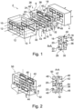
- Fig. 1 shows a fuel cell stack 2 in an exploded view.
- the fuel cell 4 comprises a fuel cell block 8, which exemplarily is of a cuboid shape. It comprises two anode channels 10 and two cathode channels 12, which extend through the fuel cell block 8 in a straight, linear manner.
- the two anode channels 10 are arranged side by side in a top portion of the fuel cell block 8 and the two cathode channels 12 are arranged side by side underneath the two anode channels 10 in a bottom portion of the fuel cell block 8.
- the anode channels 10 comprise a circumferential coating, which constitute anodes.
- the cathode channels 12 comprise a cathode coating, which constitute the respective cathodes.
- the fuel cell block 8 may be made from a ceramic material and fuel cells are created by pairwise combinations of anode channels 10 and cathode channels 12.
- the interconnecting device 6 serves to connect the fuel cells 4 to form the fuel cell stack 2 similarly to a bipolar plate. Due to the different concept of the SOFC 4 compared to conventional, two-dimensional, planar PEM fuel cells or the like, the interconnecting device 6 has a different design. It comprises a body 14 having a first interface surface 16 and a second interface surface 18. The first interface surface 16 is designed to flushly contact the fuel cell 4 on the left-hand side in fig. 1 , while the second interface surface 18 is designed to flushly contact the fuel cell 4 on the right-hand side of fig. 1 .
- the first interface surface 16 comprises two anode exhaust inputs 20 arranged side by side, while the positions of the anode exhaust inputs 20 match the positions of the two anode channels 10 of the fuel cell 4.
- the anode exhaust inputs 20 receive exhaust gas from the anode channels 10, i.e. surplus hydrogen and water vapor.
- cathode exhaust inputs 22 are provided, wherein their positions match the positions of the two cathode channels 12.
- the cathode exhaust inputs 22 receive cathode exhaust, i.e. surplus oxidant, which may be oxygen or oxygen depleted air.
- anode exhaust gas entering the anode exhaust inputs 20 is routed to an anode exhaust outlet 24, which is located at a first side 26 of the interconnecting device 6.
- surplus fuel i.e. hydrogen
- the first side 26 extends perpendicularly to both the first interface surface 16 and the second interface surface 18. In fig. 1 , it is arranged on the left-hand side. Consequently, the total flow of surplus fuel that enters the interconnecting device 6 leaves the interconnecting device 6 and is not routed into the subsequent fuel cell 4.
- Cathode exhaust which enters the cathode exhaust inlets 22, is routed to a cathode exhaust outlet 28, which is arranged at a second side 30 of the interconnecting device 6.
- the second side 30 extends perpendicularly to both the first interface surface 16 and the second interface surface 18 and is arranged at a bottom portion of the interconnecting device 6 in fig. 1 . Consequently, the whole flow of surplus oxidant, e.g. oxygen depleted air, leaves the interconnecting device 6.
- An oxidant inlet 32 is provided at a third side 34, which extends perpendicularly to the first interface surface 16 and the second interface surface 18 and is located on the right-hand side of the interconnecting device 6.
- oxidant e.g. air
- the subsequent fuel cell 4 which is arranged downstream of the interconnecting device 6, is supplied with oxidant through the oxidant inlet 32 only.
- the interconnecting devices 6 in this secondary embodiment is able to completely separate exhaust flows from the first fuel-cell 4 and the second fuel-cell 4, wherein peripheral devices may be connected with the interconnecting device 6 to further handle these exhaust and supply flows.
- the fourth side 38 perpendicularly extends between the first interface surface 16 and the second interface surface 18 and is located at a top portion of the interconnecting device 6. The exhaust outlets 24 and 28 are thus clearly separated from the inlets 36 and 40.
- the interconnecting device 6 For electrically connecting the fuel cells 4, the interconnecting device 6 comprises first electrical ports 44 on the first interface surface 16 and second electrical ports 46 on the second interface surface 18.
- the first electrical ports 44 are provided by a material section that surround the anode exhaust inlets 20, while the second electrical ports 46 surround the fuel supply ports 42. Thus, they will electrically contact the respective anode channels 10 and cathode channels 12 of two subsequent fuel cells 4 when the interconnecting device 6 is sandwiched between the respective fuel cells 4. Electrons travel through the interconnecting device 6 through an electrical conductor 47, which is integrated into the interconnecting device 6 and extends from the first electrical ports 44 and second electrical ports 46.
- the anode exhaust inlets 20 may comprise an insulating layer or a recess 48 to avoid an electrical contact between the anode channels 10 and the interconnecting device 6.
- the interconnecting device 6 may be created by a three-dimensional printing process, i.e. an additive manufacturing method, wherein the whole interconnecting device 6 may be made from a light-weight, electrically insulating material, which is able to withstand the elevated temperatures that are created in the fuel cell process.
- a light-weight, electrically insulating material which is able to withstand the elevated temperatures that are created in the fuel cell process.
- it may be Yttria Stabilized Zirconia, which is also usable as electrolyte for the SOFCs 4.
- the interconnecting device 6 may be made from an electrically conductive material. Then, a separate conductor 47 would not be required, but instead isolating means for preventing short circuits between the respective parts of the fuel cells 4.
- FIG. 2 another example of an interconnecting device 50 is provided.
- the design is generally equal to the interconnecting device 2, but comprises an oxidant passage 52 between the cathode exhaust inlets 22 and the oxidant supply ports 36, such that at least a part of cathode exhaust gas may flow into the oxidant supply ports 36 to be re-used.
- air as an oxidant may be only partially oxygen depleted and has an oxygen content that is still usable in a further fuel cell 4.
- the oxidant passage 52 may comprise an orifice 54, i.e.
- Fig. 3 and interconnecting device 56 is shown, in which cathode exhaust gas and anode exhaust gas simply flow through the interconnecting device 56 from one fuel cell 4 to a subsequent fuel cell 4.
- Anode exhaust inlets 20 are thus in a direct fluid communication with fuel supply ports 42 and cathode exhaust inlets 22 are in direct fluid communication with oxidant supply ports 36.
- air is used as oxidant, depleted air from an upstream SOFC 4 has only a marginal effect, and the fuel gas can be adjusted by pressure to be sufficient for several downstream SOFCs 4.
- the interconnecting device 56 may be made with a simpler design. It may be dimensioned to be thinner and thus more weight-saving. It is also possible to easily benefit from relatively short dimensions of each SOFC 4 and short current collection distances.
- FIG. 4 another exemplary embodiment of an interconnecting device 58 is shown, which is adapted to conform a different design of a solid oxide fuel cell 60 and which is mainly based on the design shown in Fig. 3 .
- the SOFCs 60 show electrochemical reactions in both transverse directions of the SOFCs 60 and the interconnecting device is correspondingly modified.
- Fig. 5 shows an aircraft 62, into which a fuel cell stack having a plurality of fuel cells 4 or 60 and interconnecting devices 6, 56 or 58 is arranged.
Landscapes
- Life Sciences & Earth Sciences (AREA)
- Engineering & Computer Science (AREA)
- Manufacturing & Machinery (AREA)
- Sustainable Development (AREA)
- Sustainable Energy (AREA)
- Chemical & Material Sciences (AREA)
- Chemical Kinetics & Catalysis (AREA)
- Electrochemistry (AREA)
- General Chemical & Material Sciences (AREA)
- Fuel Cell (AREA)
Abstract
Description
- The invention relates to an interconnecting device for solid oxide fuel cells, a fuel cell stack, comprising a plurality of solid oxide fuel cells and at least one such interconnecting device, as well as a vehicle having at least one fuel cell stack.
- Solid oxide fuel cells operate at high temperatures in a range of roughly 650 °C to 1000 °C. The electrolyte consists of a solid and gas-tight ceramic material, that is capable of conducting oxygen ions, but is isolating against electrons. A plurality of solid oxide fuel cells can be combined to form a fuel cell stack, wherein bipolar plates are arranged between consecutive fuel cells. The bipolar plates are attached to the anode of one of the fuel cells and the cathode of an adjacent fuel cell.
- In a fuel cell stack, hydrogen gas enters through gas channels of a first bipolar plate and reaches an anode of a fuel cell that is in contact with the first bipolar plate. At a cathode of the same fuel cell, air or oxygen is supplied through gas channels of a second bipolar plate that is in contact with the cathode of the fuel cell. During the fuel cell process, oxygen ions pass through the electrolyte and electrons move from the anode into the bipolar plate for further entry into the adjacent cell. By connecting a series of fuel cells through bipolar plates arranged between them, a fuel cell stack is formed. An electric circuit can be connected to the fuel cell stack to use the generated voltage and to maintain the fuel cell process. In common fuel cell stacks, surplus hydrogen, not converted at the individual anodes, surplus air and reaction water leave the respective bipolar plates.
- The bipolar plates fulfil a number of different functions. They distribute incoming reactants, i.e. hydrogen and air/oxygen, by their gas channels, which are also known as flow field. They carry a compressive pressure, due to the fact that a fuel cell stack is usually placed under compression, so as to ensure low contact resistances between the electrodes and the bipolar plates. Said gas distribution channels are provided by local removal of material, thus the remaining material is subjected to increased stress. The bipolar plates are also electrically connected to the fuel cells and collect the electrical current generated therein. Still further, heat that is generated in the fuel cells by the electrochemical reaction is received by the bipolar plates and may be transported out of the fuel cell by its thermal conductivity or e.g. through additional cooling channels. Commonly, a temperature gradient appears from the center of the bipolar plates towards the outer perimeter.
- It is common to produce the bipolar plates from a metallic material. The electrical current generated in the fuel cell stack is hereby transferred within the bipolar plate in a perpendicular direction to a planar cell area, which enables an efficient current collection as a comparably large area with low ohmic electronic resistance can be used. This concept is known to be a promising solution for stationery power generation application. Even though the planar concept offers low current collection losses, planar bipolar plates provide the heaviest parts in a planar stack. For example, the bipolar plates can make up to 70 % of the total weight of a planar stack.
- Compact solid oxide fuel cells (SOFC) may comprise an exemplarily cuboid fuel cell block, which comprises anode channels and cathode channels extending through the fuel cell block. The anode channels may comprise a circumferential coating, which constitute anodes. In analogy, the cathode channels may comprise a cathode coating, which constitute the respective cathodes. Such a fuel cell block may be made from a ceramic material and fuel cells are created by pairwise combinations of anode channels and cathode channels.
- A challenge with this kind of compact SOFC is that bipolar plates, such as used for two-dimensional fuel cells are not suitable. In this context, monolithic cell designs offer a major optimization potential because the bipolar plates are not mandatory to be implemented, neither for the separation of the fuel cell and the fuel and air gas channels, or for the current collection. These concepts are known to make use of a current collection in the axial direction of the cell along the in-plane cross section of the electrodes. Thus, short distances for the current collection within the electrodes are mandatory to reduce the ohmic losses of current collection. An arrangement of electrically in series connected compact SOFCs is the desired approach of this invention to keep the current collection losses low. The supply of educts and current collection for the compact SOFC, like monolithic concepts, require another interconnecting device.
- It is thus an object of the invention to propose an interconnecting device for connecting a plurality of compact solid oxide fuel cells, wherein the interconnecting device should comprise a minimum weight and a compact shape.
- This object is met by an interconnecting device for compact solid oxide fuel cells having the features of claim 1. Advantageous embodiments and further improvements may be gathered from the subclaims and the following description.
- An interconnecting device for compact solid oxide fuel cells is proposed, the interconnecting device comprising a body having a first interface surface, and a second interface surface on distinct sides of the body, wherein the first interface surface comprises at least one anode exhaust input and at least one cathode exhaust input in a distance to the at least one anode exhaust input, wherein the second interface surface comprises at least one fuel supply port and at least one oxidant supply port in a distance to the at least one fuel supply port, wherein the at least one anode exhaust input is in fluid communication with the at least one fuel supply port and/or at least one anode exhaust outlet arranged at a distance to the first interface surface and the second interface surface, wherein the at least one cathode exhaust input is in fluid communication with the at least one oxidant supply port and/or at least one cathode exhaust outlet arranged at a distance to the first interface surface and the second interface surface, wherein at least one first electrical port is arranged at or in the at least one cathode exhaust input and is connectable from the first interface surface, wherein at least one second electrical port is arranged at or in the at least one fuel supply port and is connectable from the second interface surface, and wherein the at least one first electrical port is electrically connected to the at least one second electrical port.
- The interconnecting device is thus capable of being fitted between consecutive compact SOFCs to fulfill the functions of reactant supply of fuel and air/oxygen, as well as current collection, such as is performed by the bipolar plates for one-dimensional SOFCs and at the same time takes into account the more complex geometry of compact SOFCs. The interconnecting device has a body with a plurality of sides, wherein two of the sides are intended for providing the first interface surface and the second interface surface. The first interface surface is intended to be in contact with a first fuel cell, while the second interface surface is intended to be in contact with a subsequent, adjacent second fuel cell. Both fuel cells may be provided in the form of a compact SOFCs, as explained above.
- Hence, the respective SOFCs comprise a three-dimensional shape and the anodes and cathodes are integrated in a closed circumference way to form three-dimensional gas channels. The anode and cathode are integrated within a 3D electrolyte/membrane support structure, with corresponding anode/cathode channels in an alternating manner. The first interface surface and second interface surface of the interconnecting device are adapted in size to the respective SOFCs, such that a flush contact between the SOFCs and the interface surfaces is possible. The positions of flow channels, which include the above-mentioned circumferentially arranged anodes and cathodes, match the positions of the respective anode exhaust input and cathode exhaust input as well as the fuel supply port and the oxidant supply port.
- The interconnecting device may be clamped between two consecutive fuel cells, such that dedicated fastening or installation means are not required. The interconnecting device is then able to receive flows of exhaust fluids, i.e. anode exhaust and cathode exhaust. Anode exhaust comprises unused, surplus Hydro gene, while cathode exhaust comprises oxygen depleted air or unused oxygen. The interconnecting device is capable of routing these fluid flows to a dedicated target, e.g. into respective inlets of a subsequent fuel cell and/or to outlets arranged in the interconnecting device.
- Still further, the first and second electric ports are provided to contact anodes and/or cathodes of the connected fuel cells, which may be realized by circumferential surfaces as explained above.
- It is advantageous to provide the body from an electrically isolating material, which is capable of withstanding the high temperatures that arise in the solid oxide fuel cell process. It may be feasible to create the interconnecting device through a 3D printing process, which simplifies the electrical connection between the first electrical port and the second electric port by locally including an electrically conductive material.
- It is also advantageous to provide the body from an electrically conducting material, which is capable of withstanding the high temperatures that arise in the solid oxide fuel cell process. The body may then be electrically connected either to the anode channel or the cathode channel of the upstream fuel cell only and inversely connected either to the cathode channel or the anode channel only of the downstream fuel cell. The other one of the anode channel or the cathode channel is then insulated against the body.
- In the concept of the interconnecting device according to the invention, various different designs of solid oxide fuel cells may be considered and the interconnecting device may be tailored to the desired electrical connection and the educt supply concept. A variable number of anode exhaust inputs and cathode exhaust inputs on the first interface surface may be used, as well as a variable number of respective supply outlets on the second interface surface. Different distributions of fluids are possible, as further explained below.
- In an advantageous embodiment, the first interface surface and the second interface surface are arranged on opposed sides of the body. Thus, in a simple case, a fluid may directly flow from the first interface surface to the second interface surface, i.e. without flowing through bends or curves. The respective exhaust input and supply port, that are connected to each other, may then be arranged directly behind each other, i.e. along a straight line. As bends and other redirections are not required, a thickness of the body of the interconnection device may be reduced, which in turn leads to a weight reduction. Still further, the electrical resistance in the thickness direction decreases and the flow of the respective fluids is optimized in terms of flow resistance.
- In an advantageous embodiment, the interconnecting device further comprises at least one fuel inlet arranged on a side of the body that does neither comprise the first interface surface nor the second interface surface, wherein the at least one fuel inlet is in fluid communication with the at least one fuel supply port. The at least one fuel inlet serves to supply fuel into the interconnecting device from a side that laterally extends between two consecutive fuel cells, when the interconnecting device is installed. The flow of fuel from the respective side is directed to the at least one fuel supply port on the second interface surface. The at least one fuel inlet may simply be realized in the form of an opening, a channel, a flange, or any other suitable element that is connectable to a fuel source. The fuel will flow along a bent or curved line between the fuel inlet and the respective fuel supply port.
- In an advantageous embodiment, the interconnecting device further comprises at least one oxidant inlet arranged on a side of the body that does neither comprise the first interface surface nor the second interface surface, wherein the at least one oxidant inlet is in fluid communication with the at least one oxidant supply port. In analogy to the at least one fuel inlet explained above, the at least one oxidant inlet serves to supply an additional oxidant flow from the side of the body. Again, the side may laterally extend between two consecutive fuel cells, when the interconnecting device is installed. The oxidant flows from the oxidant inlet to the respective oxidant supply port along a line that is curved or bent.
- In an advantageous embodiment, the at least one oxidant supply port is in fluid communication with both the at least one oxidant inlet and the at least one cathode exhaust input. Thus, at least one oxidant supply port receives oxidant both from the cathode exhaust input and the oxidant inlet. For example, air that flows through the cathode of a first fuel cell may be partially oxygen depleted and the remaining oxygen content may thus be used in the directly-following fuel-cell, i.e. a second fuel cell. However, it is feasible to supply additional oxidant to optimize the stoichiometry.
- An oxidant passage between the at least one cathode exhaust input and the at least one oxidant inlet may comprise an orifice, wherein the body comprises the at least one cathode exhaust outlet, and wherein the orifice is dimensioned to divide a fluid flow from the at least one cathode exhaust input to the at least one oxidant supply port and the cathode exhaust outlet in a predetermined fraction for a predetermined operating state of the respective fuel cells attached to the interconnecting device. The orifice determines, how much of remaining oxidant from a first fuel cell is used in an oxidant flow that reaches a subsequent, second fuel through the oxidant supply port. It may be feasible to re-use only a minor part of surplus oxidant from the first fuel cell and to discharge the remaining major part of the surplus oxidant. The orifice may be tailored to a certain operating state of the respective fuel cells, e.g. a state in which the fuel cell stack delivers 75% power or any other suitable operating state.
- Instead of an orifice, cross-sectional surfaces of passages between the at least one oxidant inlet, the at least one cathode exhaust inlet, the at least one cathode exhaust outlet and the at least one oxidant supply port may be as large as possible in the restricted available space inside the body. The individual flow divisions are then determined by valves, orifices, suctioning devices, pumps or any other suitable devices outside the body and connected to the oxidant inlet and the cathode exhaust outlet.
- In an advantageous embodiment, the first interface surface comprises at least one pair of anode exhaust input and cathode exhaust input, wherein the second interface surface comprises at least one pair of fuel supply port and oxidant supply port. Compact arrangements of several SOFCs in a single block may be combined with such an interconnecting device to form a low-weight, compact SOFC stack.
- In an advantageous embodiment, the at least one cathode exhaust input and the at least one oxidant supply port comprise an opening, which has a rectangular, round or otherwise regular shape. However, this depends on the fuel cells in contact with the interconnecting device. A rectangular shape may particularly be advantageous in terms of compactness of the SOFC itself and the stack created with these SOFCs.
- In an advantageous embodiment, the first electrical port and the second electrical port surround the respective opening of the at least one cathode exhaust input and at least one oxidant supply port at least in the respective interface surface. The electrical ports may thus be realized in the form of a ring that surrounds the respective opening. A conductor connected to the electrical ports does not necessarily need to have a ring-shaped form.
- In an advantageous embodiment, the body has a cuboid shape having a width, height, and depth, wherein the first interface surface and the second interface surface are opposed in a depth-wise direction, and wherein the width and height of the body exceeds the depth of the body. The body may be clamped between two consecutive SOFC, which may comprise a rectangular interface surface. By providing a small depth of the body, the fuel cell stack may be rather compact.
- In an advantageous embodiment, the body is made from a ceramic material. Thus, the interconnecting device is capable of resisting high temperatures and comprises a rather low weight.
- The invention further relates to a fuel cell stack, comprising a plurality of solid oxide fuel cells and at least one interconnecting device according to the preceding description arranged between two consecutive solid oxide fuel cells.
- In an advantageous embodiment, the fuel cells comprise at least one column with at least one pair of an anode channel and a cathode channel arranged in an alternating manner in a block.
- The invention further relates to a vehicle comprising at least one such fuel cell stack.
- In an advantageous embodiment, the vehicle is an aircraft. The fuel cell stack may be integrated into an engine nacelle or in an unpressurized and preferably ventilated section of a fuselage or a component attached to the fuselage.
- In the following, the attached drawings are used to illustrate exemplary embodiments in more detail. The illustrations are schematic and not to scale. Identical reference numerals refer to identical or similar elements. They show:
- Fig. 1
- a fuel cell stack with SOFCs and an interconnecting device in a first example in an exploded view.
- Fig. 2
- an interconnecting device in a second example.
- Fig. 3
- an interconnecting device in a third example.
- Fig. 4
- an interconnecting device in a fourth example.
- Fig. 5
- an aircraft.
-
Fig. 1 shows afuel cell stack 2 in an exploded view. Here, two solid oxide fuel cells 4 (SOFC) are shown, which together enclose an interconnectingdevice 6. Thefuel cell 4 comprises a fuel cell block 8, which exemplarily is of a cuboid shape. It comprises twoanode channels 10 and twocathode channels 12, which extend through the fuel cell block 8 in a straight, linear manner. Exemplarily, the twoanode channels 10 are arranged side by side in a top portion of the fuel cell block 8 and the twocathode channels 12 are arranged side by side underneath the twoanode channels 10 in a bottom portion of the fuel cell block 8. Theanode channels 10 comprise a circumferential coating, which constitute anodes. In analogy, thecathode channels 12 comprise a cathode coating, which constitute the respective cathodes. The fuel cell block 8 may be made from a ceramic material and fuel cells are created by pairwise combinations ofanode channels 10 andcathode channels 12. - The interconnecting
device 6 serves to connect thefuel cells 4 to form thefuel cell stack 2 similarly to a bipolar plate. Due to the different concept of theSOFC 4 compared to conventional, two-dimensional, planar PEM fuel cells or the like, the interconnectingdevice 6 has a different design. It comprises abody 14 having afirst interface surface 16 and asecond interface surface 18. Thefirst interface surface 16 is designed to flushly contact thefuel cell 4 on the left-hand side infig. 1 , while thesecond interface surface 18 is designed to flushly contact thefuel cell 4 on the right-hand side offig. 1 . - The
first interface surface 16 comprises twoanode exhaust inputs 20 arranged side by side, while the positions of theanode exhaust inputs 20 match the positions of the twoanode channels 10 of thefuel cell 4. Theanode exhaust inputs 20 receive exhaust gas from theanode channels 10, i.e. surplus hydrogen and water vapor. - Underneath, two
cathode exhaust inputs 22 are provided, wherein their positions match the positions of the twocathode channels 12. Thecathode exhaust inputs 22 receive cathode exhaust, i.e. surplus oxidant, which may be oxygen or oxygen depleted air. - In this exemplary embodiment, anode exhaust gas entering the
anode exhaust inputs 20 is routed to ananode exhaust outlet 24, which is located at afirst side 26 of the interconnectingdevice 6. This means, that surplus fuel, i.e. hydrogen, exits the interconnectingdevice 6 through theanode exhaust outlet 24. Thefirst side 26 extends perpendicularly to both thefirst interface surface 16 and thesecond interface surface 18. Infig. 1 , it is arranged on the left-hand side. Consequently, the total flow of surplus fuel that enters the interconnectingdevice 6 leaves the interconnectingdevice 6 and is not routed into thesubsequent fuel cell 4. - Cathode exhaust, which enters the
cathode exhaust inlets 22, is routed to acathode exhaust outlet 28, which is arranged at asecond side 30 of the interconnectingdevice 6. Thesecond side 30 extends perpendicularly to both thefirst interface surface 16 and thesecond interface surface 18 and is arranged at a bottom portion of the interconnectingdevice 6 infig. 1 . Consequently, the whole flow of surplus oxidant, e.g. oxygen depleted air, leaves the interconnectingdevice 6. - An
oxidant inlet 32 is provided at athird side 34, which extends perpendicularly to thefirst interface surface 16 and thesecond interface surface 18 and is located on the right-hand side of the interconnectingdevice 6. Here, oxidant, e.g. air, enters the interconnectingdevice 6 and flows to oxidantsupply ports 36 arranged on thefirst interface surface 18. Hence, thesubsequent fuel cell 4, which is arranged downstream of the interconnectingdevice 6, is supplied with oxidant through theoxidant inlet 32 only. - On the
fourth side 38,fuel inlets 40 are provided, through which fuel flows to fuelsupply ports 42 arranged on thesecond interface surface 18 to enter theanode channels 10 of thesubsequent fuel cell 4. Consequently, the interconnectingdevices 6 in this secondary embodiment is able to completely separate exhaust flows from the first fuel-cell 4 and the second fuel-cell 4, wherein peripheral devices may be connected with the interconnectingdevice 6 to further handle these exhaust and supply flows. In this example, thefourth side 38 perpendicularly extends between thefirst interface surface 16 and thesecond interface surface 18 and is located at a top portion of the interconnectingdevice 6. Theexhaust outlets inlets - For electrically connecting the
fuel cells 4, the interconnectingdevice 6 comprises firstelectrical ports 44 on thefirst interface surface 16 and secondelectrical ports 46 on thesecond interface surface 18. The firstelectrical ports 44 are provided by a material section that surround theanode exhaust inlets 20, while the secondelectrical ports 46 surround thefuel supply ports 42. Thus, they will electrically contact therespective anode channels 10 andcathode channels 12 of twosubsequent fuel cells 4 when the interconnectingdevice 6 is sandwiched between therespective fuel cells 4. Electrons travel through the interconnectingdevice 6 through anelectrical conductor 47, which is integrated into the interconnectingdevice 6 and extends from the firstelectrical ports 44 and secondelectrical ports 46. On thefirst interface surface 16, theanode exhaust inlets 20 may comprise an insulating layer or arecess 48 to avoid an electrical contact between theanode channels 10 and the interconnectingdevice 6. - The interconnecting
device 6 may be created by a three-dimensional printing process, i.e. an additive manufacturing method, wherein thewhole interconnecting device 6 may be made from a light-weight, electrically insulating material, which is able to withstand the elevated temperatures that are created in the fuel cell process. For example, it may be Yttria Stabilized Zirconia, which is also usable as electrolyte for theSOFCs 4. - In other variants, which are not explicitly shown as examples, the interconnecting
device 6 may be made from an electrically conductive material. Then, aseparate conductor 47 would not be required, but instead isolating means for preventing short circuits between the respective parts of thefuel cells 4. - In
Fig. 2 , another example of an interconnectingdevice 50 is provided. Here, the design is generally equal to the interconnectingdevice 2, but comprises anoxidant passage 52 between thecathode exhaust inlets 22 and theoxidant supply ports 36, such that at least a part of cathode exhaust gas may flow into theoxidant supply ports 36 to be re-used. For example, air as an oxidant may be only partially oxygen depleted and has an oxygen content that is still usable in afurther fuel cell 4. Theoxidant passage 52 may comprise anorifice 54, i.e. constricted space between thecathode exhaust inlet 22 and theoxidant supply port 36, which orifice 52 is dimensioned to divide a fluid flow from thecathode exhaust inputs 22 to the at least oneoxidant supply port 36 and thecathode exhaust outlets 28 in a predetermined fraction for a predetermined operating state of therespective fuel cells 4 attached to the interconnectingdevice 50. - In
Fig. 3 , and interconnectingdevice 56 is shown, in which cathode exhaust gas and anode exhaust gas simply flow through the interconnectingdevice 56 from onefuel cell 4 to asubsequent fuel cell 4.Anode exhaust inlets 20 are thus in a direct fluid communication withfuel supply ports 42 andcathode exhaust inlets 22 are in direct fluid communication withoxidant supply ports 36. If air is used as oxidant, depleted air from anupstream SOFC 4 has only a marginal effect, and the fuel gas can be adjusted by pressure to be sufficient for severaldownstream SOFCs 4. This design has several considerable advantages. For instance, due to the simple through-flow of both reactants, the interconnectingdevice 56 may be made with a simpler design. It may be dimensioned to be thinner and thus more weight-saving. It is also possible to easily benefit from relatively short dimensions of eachSOFC 4 and short current collection distances. - In
Fig. 4 , another exemplary embodiment of an interconnectingdevice 58 is shown, which is adapted to conform a different design of a solidoxide fuel cell 60 and which is mainly based on the design shown inFig. 3 . However, theSOFCs 60 show electrochemical reactions in both transverse directions of theSOFCs 60 and the interconnecting device is correspondingly modified. -
Fig. 5 shows anaircraft 62, into which a fuel cell stack having a plurality offuel cells interconnecting devices -
- 2
- fuel cell stack
- 4
- fuel cell
- 6
- interconnecting device
- 8
- fuel cell block
- 10
- anode channel
- 12
- cathode channel
- 14
- body
- 16
- first interface surface
- 18
- second interface surface
- 20
- anode exhaust input
- 22
- cathode exhaust input
- 24
- anode exhaust outlet
- 26
- first side
- 28
- cathode exhaust outlet
- 30
- second side
- 32
- oxidant inlet
- 34
- third side
- 36
- oxidant supply port
- 38
- fourth side
- 40
- fuel inlet
- 42
- fuel supply port
- 44
- first electrical port
- 46
- second electrical port
- 47
- conductor
- 48
- layer / recess
- 50
- interconnecting device
- 52
- oxidant passage
- 54
- orifice
- 56
- interconnecting device
- 58
- interconnecting device
- 60
- fuel cell
- 62
- aircraft
Claims (15)
- An interconnecting device (6, 50, 56, 58) for compact solid oxide fuel cells (4, 60), the interconnecting device (6, 50, 56, 58) comprising a body (14) having a first interface surface (16), and a second interface surface (18) on distinct sides of the body (14),wherein the first interface surface (16) comprises at least one anode exhaust input (20) and at least one cathode exhaust input (22) in a distance to the at least one anode exhaust input (20),wherein the second interface surface (18) comprises at least one fuel supply port (42) and at least one oxidant supply port (42) in a distance to the at least one fuel supply port (42),wherein the at least one anode exhaust input (20) is in fluid communication with the at least one fuel supply port (42) and/or at least one anode exhaust outlet (24) arranged at a distance to the first interface surface (16) and the second interface surface (18),wherein the at least one cathode exhaust input (22) is in fluid communication with the at least one oxidant supply port (42) and/or at least one cathode exhaust outlet (28) arranged at a distance to the first interface surface (16) and the second interface surface (18),wherein at least one first electrical port (44) is arranged at or in the at least one cathode exhaust input (22) and is connectable from the first interface surface (16),wherein at least one second electrical port (46) is arranged at or in the at least one fuel supply port (42) and is connectable from the second interface surface (18), andwherein the at least one first electrical port (44) is electrically connected to the at least one second electrical port (46).
- Interconnecting device (6, 50, 56, 58) of claim 1,
wherein the first interface surface (16) and the second interface surface (18) are arranged on opposed sides of the body (14). - Interconnecting device (6, 50, 56, 58) of claim 1 or 2,further comprising at least one fuel inlet (40) arranged on a side of the body (14) that does neither comprise the first interface surface (16) nor the second interface surface (18),wherein the at least one fuel inlet (40) is in fluid communication with the at least one fuel supply port (42).
- Interconnecting device (6, 50, 56, 58) of any of the preceding claims,further comprising at least one oxidant inlet (32) arranged on a side of the body (14) that does neither comprise the first interface surface (16) nor the second interface surface (18),wherein the at least one oxidant inlet (32) is in fluid communication with the at least one oxidant supply port (42).
- Interconnecting device (6, 50, 56, 58) of claim 4,
wherein the at least one oxidant supply port (42) is in fluid communication with both the at least one oxidant inlet (32) and the at least one cathode exhaust input (22). - Interconnecting device (6, 50, 56, 58) of claim 5,Wherein an oxidant passage (52) between the at least one cathode exhaust input (22) and the at least one oxidant inlet (32) comprises an orifice (54),wherein the body (14) comprises the at least one cathode exhaust outlet (28), andwherein the orifice (54) is dimensioned to divide a fluid flow from the at least one cathode exhaust input (22) to the at least one oxidant supply port (42) and the cathode exhaust outlet (28) in a predetermined fraction for a predetermined operating state of the respective fuel cells (4, 60) attached to the interconnecting device (6, 50, 56, 58).
- Interconnecting device (6, 50, 56, 58) of any of the preceding claims,wherein the first interface surface (16) comprises at least one pair of anode exhaust input (20) and cathode exhaust input (22), andwherein the second interface surface (18) comprises at least one pair of fuel supply port (42) and oxidant supply port (42).
- Interconnecting device (6, 50, 56, 58) of any of the preceding claims
wherein the at least one cathode exhaust input (22) and the at least one oxidant supply port (42) comprise an opening, which has a rectangular, round or otherwise regular shape. - Interconnecting device (6, 50, 56, 58) of claim 8,
wherein the first electrical port (44) and the second electrical port (46) surround the respective opening of the at least one cathode exhaust input (22) and at least one oxidant supply port (42) at least in the respective interface surface. - Interconnecting device (6, 50, 56, 58) of any of the preceding claims,
wherein the body (14) has a cuboid shape having a width, height, and depth, wherein the first interface surface (16) and the second interface surface (18) are opposed in a depth-wise direction, and wherein the width and height of the body (14) exceeds the depth of the body (14). - Interconnecting device (6, 50, 56, 58) of any of the preceding claims,
wherein the body (14) is made from a ceramic or metallic material. - Fuel cell stack, comprising a plurality of solid oxide fuel cells (4, 60) and at least one interconnecting device (6, 50, 56, 58) according to any of the preceding claims arranged between two consecutive solid oxide fuel cells (4, 60).
- Fuel cell stack of claim 12, wherein the fuel cells (4, 60) comprise at least one column with at least one pair of an anode channel (10) and a cathode channel (12) arranged in an alternating manner in a block.
- Vehicle (62), comprising at least one fuel cell stack of claim 12 or 13.
- Vehicle (62) of claim 14, wherein the vehicle (62) is an aircraft (62).
Priority Applications (3)
| Application Number | Priority Date | Filing Date | Title |
|---|---|---|---|
| EP22154251.7A EP4220787B1 (en) | 2022-01-31 | 2022-01-31 | Interconnecting device for solid oxide fuel cells and a fuel cell stack comprising the same |
| US18/160,626 US20230246204A1 (en) | 2022-01-31 | 2023-01-27 | Interconnecting device for solid oxide fuel cells and a fuel cell stack comprising the same |
| CN202310085999.3A CN116525905A (en) | 2022-01-31 | 2023-01-29 | Interconnect device for solid oxide fuel cell and fuel cell stack including same |
Applications Claiming Priority (1)
| Application Number | Priority Date | Filing Date | Title |
|---|---|---|---|
| EP22154251.7A EP4220787B1 (en) | 2022-01-31 | 2022-01-31 | Interconnecting device for solid oxide fuel cells and a fuel cell stack comprising the same |
Publications (2)
| Publication Number | Publication Date |
|---|---|
| EP4220787A1 true EP4220787A1 (en) | 2023-08-02 |
| EP4220787B1 EP4220787B1 (en) | 2024-09-04 |
Family
ID=80123129
Family Applications (1)
| Application Number | Title | Priority Date | Filing Date |
|---|---|---|---|
| EP22154251.7A Active EP4220787B1 (en) | 2022-01-31 | 2022-01-31 | Interconnecting device for solid oxide fuel cells and a fuel cell stack comprising the same |
Country Status (3)
| Country | Link |
|---|---|
| US (1) | US20230246204A1 (en) |
| EP (1) | EP4220787B1 (en) |
| CN (1) | CN116525905A (en) |
Citations (3)
| Publication number | Priority date | Publication date | Assignee | Title |
|---|---|---|---|---|
| US20050282051A1 (en) * | 2003-08-28 | 2005-12-22 | Zhigang Zhou | Integrated honeycomb solid electrolyte fuel cells |
| US20090123810A1 (en) * | 2007-11-08 | 2009-05-14 | Alan Devoe | Fuel cell device and system |
| US20110117471A1 (en) * | 2009-11-16 | 2011-05-19 | Alan Devoe | Fuel cell device |
-
2022
- 2022-01-31 EP EP22154251.7A patent/EP4220787B1/en active Active
-
2023
- 2023-01-27 US US18/160,626 patent/US20230246204A1/en active Pending
- 2023-01-29 CN CN202310085999.3A patent/CN116525905A/en active Pending
Patent Citations (3)
| Publication number | Priority date | Publication date | Assignee | Title |
|---|---|---|---|---|
| US20050282051A1 (en) * | 2003-08-28 | 2005-12-22 | Zhigang Zhou | Integrated honeycomb solid electrolyte fuel cells |
| US20090123810A1 (en) * | 2007-11-08 | 2009-05-14 | Alan Devoe | Fuel cell device and system |
| US20110117471A1 (en) * | 2009-11-16 | 2011-05-19 | Alan Devoe | Fuel cell device |
Also Published As
| Publication number | Publication date |
|---|---|
| US20230246204A1 (en) | 2023-08-03 |
| CN116525905A (en) | 2023-08-01 |
| EP4220787B1 (en) | 2024-09-04 |
Similar Documents
| Publication | Publication Date | Title |
|---|---|---|
| JP3511206B2 (en) | PEM fuel cell assembly having a plurality of parallel fuel cell substacks | |
| EP4145573A1 (en) | Fuel cell, and bipolar plate and bipolar plate assembly for fuel cell | |
| US8445157B2 (en) | Fuel cell stack components | |
| US8105731B2 (en) | Fuel cell system | |
| US10396389B2 (en) | Fuel cell stack | |
| JP4764597B2 (en) | Solid oxide fuel cell and fuel cell stack | |
| CN102906920B (en) | Solid oxide fuel cell | |
| US20090042075A1 (en) | Fuel Cell Stack | |
| US9748583B2 (en) | Flow field plate for improved coolant flow | |
| US8927170B2 (en) | Flow field plate for reduced pressure drop in coolant | |
| US9385381B2 (en) | Fuel cell stack | |
| US10741852B2 (en) | Bipolar plate for an electrochemical reactor with a compact homogenization zone and a low pressure differential | |
| CN110998940B (en) | Cell structure of fuel cell and control method of cell structure of fuel cell | |
| EP1685621B1 (en) | Multi-cell fuel layer and system | |
| JP2017528869A (en) | Electrochemical reactor to harmonize pressure drop in cathode homogenization area and anode homogenization area | |
| US20110091784A1 (en) | Fuel cell system | |
| WO2000002267A2 (en) | Internal cooling arrangement for undulate mea fuel cell stack | |
| US20230246204A1 (en) | Interconnecting device for solid oxide fuel cells and a fuel cell stack comprising the same | |
| US20160204461A1 (en) | Fuel cell system including multiple fuel cell stacks | |
| KR101889550B1 (en) | A separating plate of solid oxide fuel cell stack using joint process | |
| US12255359B2 (en) | Fuel cell stack comprising variable bipolar plates | |
| JP2023144595A (en) | Electrochemical reaction cell stack | |
| JP2017126472A (en) | Fuel cell | |
| US20250092538A1 (en) | Cross-flow component for electrochemical device | |
| EP4250408A2 (en) | Fuel cell stack assembly including heat sink inserts |
Legal Events
| Date | Code | Title | Description |
|---|---|---|---|
| PUAI | Public reference made under article 153(3) epc to a published international application that has entered the european phase |
Free format text: ORIGINAL CODE: 0009012 |
|
| STAA | Information on the status of an ep patent application or granted ep patent |
Free format text: STATUS: THE APPLICATION HAS BEEN PUBLISHED |
|
| AK | Designated contracting states |
Kind code of ref document: A1 Designated state(s): AL AT BE BG CH CY CZ DE DK EE ES FI FR GB GR HR HU IE IS IT LI LT LU LV MC MK MT NL NO PL PT RO RS SE SI SK SM TR |
|
| STAA | Information on the status of an ep patent application or granted ep patent |
Free format text: STATUS: REQUEST FOR EXAMINATION WAS MADE |
|
| 17P | Request for examination filed |
Effective date: 20240131 |
|
| RBV | Designated contracting states (corrected) |
Designated state(s): AL AT BE BG CH CY CZ DE DK EE ES FI FR GB GR HR HU IE IS IT LI LT LU LV MC MK MT NL NO PL PT RO RS SE SI SK SM TR |
|
| GRAP | Despatch of communication of intention to grant a patent |
Free format text: ORIGINAL CODE: EPIDOSNIGR1 |
|
| STAA | Information on the status of an ep patent application or granted ep patent |
Free format text: STATUS: GRANT OF PATENT IS INTENDED |
|
| RIC1 | Information provided on ipc code assigned before grant |
Ipc: H01M 8/12 20160101ALN20240313BHEP Ipc: H01M 8/2483 20160101ALI20240313BHEP Ipc: H01M 8/2435 20160101AFI20240313BHEP |
|
| INTG | Intention to grant announced |
Effective date: 20240402 |
|
| GRAS | Grant fee paid |
Free format text: ORIGINAL CODE: EPIDOSNIGR3 |
|
| GRAA | (expected) grant |
Free format text: ORIGINAL CODE: 0009210 |
|
| STAA | Information on the status of an ep patent application or granted ep patent |
Free format text: STATUS: THE PATENT HAS BEEN GRANTED |
|
| AK | Designated contracting states |
Kind code of ref document: B1 Designated state(s): AL AT BE BG CH CY CZ DE DK EE ES FI FR GB GR HR HU IE IS IT LI LT LU LV MC MK MT NL NO PL PT RO RS SE SI SK SM TR |
|
| REG | Reference to a national code |
Ref country code: GB Ref legal event code: FG4D |
|
| REG | Reference to a national code |
Ref country code: CH Ref legal event code: EP |
|
| REG | Reference to a national code |
Ref country code: IE Ref legal event code: FG4D |
|
| REG | Reference to a national code |
Ref country code: DE Ref legal event code: R096 Ref document number: 602022005753 Country of ref document: DE |
|
| REG | Reference to a national code |
Ref country code: LT Ref legal event code: MG9D |
|
| REG | Reference to a national code |
Ref country code: NL Ref legal event code: MP Effective date: 20240904 |
|
| PG25 | Lapsed in a contracting state [announced via postgrant information from national office to epo] |
Ref country code: NO Free format text: LAPSE BECAUSE OF FAILURE TO SUBMIT A TRANSLATION OF THE DESCRIPTION OR TO PAY THE FEE WITHIN THE PRESCRIBED TIME-LIMIT Effective date: 20241204 |
|
| PG25 | Lapsed in a contracting state [announced via postgrant information from national office to epo] |
Ref country code: PL Free format text: LAPSE BECAUSE OF FAILURE TO SUBMIT A TRANSLATION OF THE DESCRIPTION OR TO PAY THE FEE WITHIN THE PRESCRIBED TIME-LIMIT Effective date: 20240904 Ref country code: GR Free format text: LAPSE BECAUSE OF FAILURE TO SUBMIT A TRANSLATION OF THE DESCRIPTION OR TO PAY THE FEE WITHIN THE PRESCRIBED TIME-LIMIT Effective date: 20241205 Ref country code: FI Free format text: LAPSE BECAUSE OF FAILURE TO SUBMIT A TRANSLATION OF THE DESCRIPTION OR TO PAY THE FEE WITHIN THE PRESCRIBED TIME-LIMIT Effective date: 20240904 |
|
| PG25 | Lapsed in a contracting state [announced via postgrant information from national office to epo] |
Ref country code: BG Free format text: LAPSE BECAUSE OF FAILURE TO SUBMIT A TRANSLATION OF THE DESCRIPTION OR TO PAY THE FEE WITHIN THE PRESCRIBED TIME-LIMIT Effective date: 20240904 |
|
| PG25 | Lapsed in a contracting state [announced via postgrant information from national office to epo] |
Ref country code: LV Free format text: LAPSE BECAUSE OF FAILURE TO SUBMIT A TRANSLATION OF THE DESCRIPTION OR TO PAY THE FEE WITHIN THE PRESCRIBED TIME-LIMIT Effective date: 20240904 |
|
| PG25 | Lapsed in a contracting state [announced via postgrant information from national office to epo] |
Ref country code: HR Free format text: LAPSE BECAUSE OF FAILURE TO SUBMIT A TRANSLATION OF THE DESCRIPTION OR TO PAY THE FEE WITHIN THE PRESCRIBED TIME-LIMIT Effective date: 20240904 |
|
| PG25 | Lapsed in a contracting state [announced via postgrant information from national office to epo] |
Ref country code: ES Free format text: LAPSE BECAUSE OF FAILURE TO SUBMIT A TRANSLATION OF THE DESCRIPTION OR TO PAY THE FEE WITHIN THE PRESCRIBED TIME-LIMIT Effective date: 20240904 Ref country code: RS Free format text: LAPSE BECAUSE OF FAILURE TO SUBMIT A TRANSLATION OF THE DESCRIPTION OR TO PAY THE FEE WITHIN THE PRESCRIBED TIME-LIMIT Effective date: 20241204 |
|
| PG25 | Lapsed in a contracting state [announced via postgrant information from national office to epo] |
Ref country code: RS Free format text: LAPSE BECAUSE OF FAILURE TO SUBMIT A TRANSLATION OF THE DESCRIPTION OR TO PAY THE FEE WITHIN THE PRESCRIBED TIME-LIMIT Effective date: 20241204 Ref country code: PL Free format text: LAPSE BECAUSE OF FAILURE TO SUBMIT A TRANSLATION OF THE DESCRIPTION OR TO PAY THE FEE WITHIN THE PRESCRIBED TIME-LIMIT Effective date: 20240904 Ref country code: NO Free format text: LAPSE BECAUSE OF FAILURE TO SUBMIT A TRANSLATION OF THE DESCRIPTION OR TO PAY THE FEE WITHIN THE PRESCRIBED TIME-LIMIT Effective date: 20241204 Ref country code: LV Free format text: LAPSE BECAUSE OF FAILURE TO SUBMIT A TRANSLATION OF THE DESCRIPTION OR TO PAY THE FEE WITHIN THE PRESCRIBED TIME-LIMIT Effective date: 20240904 Ref country code: HR Free format text: LAPSE BECAUSE OF FAILURE TO SUBMIT A TRANSLATION OF THE DESCRIPTION OR TO PAY THE FEE WITHIN THE PRESCRIBED TIME-LIMIT Effective date: 20240904 Ref country code: GR Free format text: LAPSE BECAUSE OF FAILURE TO SUBMIT A TRANSLATION OF THE DESCRIPTION OR TO PAY THE FEE WITHIN THE PRESCRIBED TIME-LIMIT Effective date: 20241205 Ref country code: FI Free format text: LAPSE BECAUSE OF FAILURE TO SUBMIT A TRANSLATION OF THE DESCRIPTION OR TO PAY THE FEE WITHIN THE PRESCRIBED TIME-LIMIT Effective date: 20240904 Ref country code: ES Free format text: LAPSE BECAUSE OF FAILURE TO SUBMIT A TRANSLATION OF THE DESCRIPTION OR TO PAY THE FEE WITHIN THE PRESCRIBED TIME-LIMIT Effective date: 20240904 Ref country code: BG Free format text: LAPSE BECAUSE OF FAILURE TO SUBMIT A TRANSLATION OF THE DESCRIPTION OR TO PAY THE FEE WITHIN THE PRESCRIBED TIME-LIMIT Effective date: 20240904 |
|
| REG | Reference to a national code |
Ref country code: AT Ref legal event code: MK05 Ref document number: 1721369 Country of ref document: AT Kind code of ref document: T Effective date: 20240904 |
|
| PG25 | Lapsed in a contracting state [announced via postgrant information from national office to epo] |
Ref country code: NL Free format text: LAPSE BECAUSE OF FAILURE TO SUBMIT A TRANSLATION OF THE DESCRIPTION OR TO PAY THE FEE WITHIN THE PRESCRIBED TIME-LIMIT Effective date: 20240904 |
|
| PG25 | Lapsed in a contracting state [announced via postgrant information from national office to epo] |
Ref country code: IS Free format text: LAPSE BECAUSE OF FAILURE TO SUBMIT A TRANSLATION OF THE DESCRIPTION OR TO PAY THE FEE WITHIN THE PRESCRIBED TIME-LIMIT Effective date: 20250104 Ref country code: PT Free format text: LAPSE BECAUSE OF FAILURE TO SUBMIT A TRANSLATION OF THE DESCRIPTION OR TO PAY THE FEE WITHIN THE PRESCRIBED TIME-LIMIT Effective date: 20250106 |
|
| PG25 | Lapsed in a contracting state [announced via postgrant information from national office to epo] |
Ref country code: SM Free format text: LAPSE BECAUSE OF FAILURE TO SUBMIT A TRANSLATION OF THE DESCRIPTION OR TO PAY THE FEE WITHIN THE PRESCRIBED TIME-LIMIT Effective date: 20240904 Ref country code: RO Free format text: LAPSE BECAUSE OF FAILURE TO SUBMIT A TRANSLATION OF THE DESCRIPTION OR TO PAY THE FEE WITHIN THE PRESCRIBED TIME-LIMIT Effective date: 20240904 |
|
| PG25 | Lapsed in a contracting state [announced via postgrant information from national office to epo] |
Ref country code: AT Free format text: LAPSE BECAUSE OF FAILURE TO SUBMIT A TRANSLATION OF THE DESCRIPTION OR TO PAY THE FEE WITHIN THE PRESCRIBED TIME-LIMIT Effective date: 20240904 Ref country code: EE Free format text: LAPSE BECAUSE OF FAILURE TO SUBMIT A TRANSLATION OF THE DESCRIPTION OR TO PAY THE FEE WITHIN THE PRESCRIBED TIME-LIMIT Effective date: 20240904 |
|
| PG25 | Lapsed in a contracting state [announced via postgrant information from national office to epo] |
Ref country code: CZ Free format text: LAPSE BECAUSE OF FAILURE TO SUBMIT A TRANSLATION OF THE DESCRIPTION OR TO PAY THE FEE WITHIN THE PRESCRIBED TIME-LIMIT Effective date: 20240904 |
|
| PG25 | Lapsed in a contracting state [announced via postgrant information from national office to epo] |
Ref country code: SK Free format text: LAPSE BECAUSE OF FAILURE TO SUBMIT A TRANSLATION OF THE DESCRIPTION OR TO PAY THE FEE WITHIN THE PRESCRIBED TIME-LIMIT Effective date: 20240904 Ref country code: IT Free format text: LAPSE BECAUSE OF FAILURE TO SUBMIT A TRANSLATION OF THE DESCRIPTION OR TO PAY THE FEE WITHIN THE PRESCRIBED TIME-LIMIT Effective date: 20240904 |
|
| REG | Reference to a national code |
Ref country code: DE Ref legal event code: R097 Ref document number: 602022005753 Country of ref document: DE |
|
| PG25 | Lapsed in a contracting state [announced via postgrant information from national office to epo] |
Ref country code: DK Free format text: LAPSE BECAUSE OF FAILURE TO SUBMIT A TRANSLATION OF THE DESCRIPTION OR TO PAY THE FEE WITHIN THE PRESCRIBED TIME-LIMIT Effective date: 20240904 |
|
| PLBE | No opposition filed within time limit |
Free format text: ORIGINAL CODE: 0009261 |
|
| STAA | Information on the status of an ep patent application or granted ep patent |
Free format text: STATUS: NO OPPOSITION FILED WITHIN TIME LIMIT |
|
| 26N | No opposition filed |
Effective date: 20250605 |
|
| REG | Reference to a national code |
Ref country code: CH Ref legal event code: PL |
|
| PG25 | Lapsed in a contracting state [announced via postgrant information from national office to epo] |
Ref country code: SE Free format text: LAPSE BECAUSE OF FAILURE TO SUBMIT A TRANSLATION OF THE DESCRIPTION OR TO PAY THE FEE WITHIN THE PRESCRIBED TIME-LIMIT Effective date: 20240904 |
|
| PG25 | Lapsed in a contracting state [announced via postgrant information from national office to epo] |
Ref country code: LU Free format text: LAPSE BECAUSE OF NON-PAYMENT OF DUE FEES Effective date: 20250131 Ref country code: MC Free format text: LAPSE BECAUSE OF FAILURE TO SUBMIT A TRANSLATION OF THE DESCRIPTION OR TO PAY THE FEE WITHIN THE PRESCRIBED TIME-LIMIT Effective date: 20240904 |
|
| PG25 | Lapsed in a contracting state [announced via postgrant information from national office to epo] |
Ref country code: BE Free format text: LAPSE BECAUSE OF NON-PAYMENT OF DUE FEES Effective date: 20250131 |
|
| PG25 | Lapsed in a contracting state [announced via postgrant information from national office to epo] |
Ref country code: CH Free format text: LAPSE BECAUSE OF NON-PAYMENT OF DUE FEES Effective date: 20250131 |
|
| REG | Reference to a national code |
Ref country code: BE Ref legal event code: MM Effective date: 20250131 |
|
| PG25 | Lapsed in a contracting state [announced via postgrant information from national office to epo] |
Ref country code: IE Free format text: LAPSE BECAUSE OF NON-PAYMENT OF DUE FEES Effective date: 20250131 |
|
| PGFP | Annual fee paid to national office [announced via postgrant information from national office to epo] |
Ref country code: GB Payment date: 20260123 Year of fee payment: 5 |
|
| PGFP | Annual fee paid to national office [announced via postgrant information from national office to epo] |
Ref country code: DE Payment date: 20260121 Year of fee payment: 5 |
|
| PGFP | Annual fee paid to national office [announced via postgrant information from national office to epo] |
Ref country code: FR Payment date: 20260123 Year of fee payment: 5 |