EP4220656A1 - Information processing system, information processing method, and information processing program - Google Patents
Information processing system, information processing method, and information processing program Download PDFInfo
- Publication number
- EP4220656A1 EP4220656A1 EP21871970.6A EP21871970A EP4220656A1 EP 4220656 A1 EP4220656 A1 EP 4220656A1 EP 21871970 A EP21871970 A EP 21871970A EP 4220656 A1 EP4220656 A1 EP 4220656A1
- Authority
- EP
- European Patent Office
- Prior art keywords
- information processing
- information
- processing device
- medical image
- execution result
- Prior art date
- Legal status (The legal status is an assumption and is not a legal conclusion. Google has not performed a legal analysis and makes no representation as to the accuracy of the status listed.)
- Pending
Links
Images




Classifications
-
- G—PHYSICS
- G09—EDUCATION; CRYPTOGRAPHY; DISPLAY; ADVERTISING; SEALS
- G09G—ARRANGEMENTS OR CIRCUITS FOR CONTROL OF INDICATING DEVICES USING STATIC MEANS TO PRESENT VARIABLE INFORMATION
- G09G5/00—Control arrangements or circuits for visual indicators common to cathode-ray tube indicators and other visual indicators
- G09G5/14—Display of multiple viewports
-
- G—PHYSICS
- G16—INFORMATION AND COMMUNICATION TECHNOLOGY [ICT] SPECIALLY ADAPTED FOR SPECIFIC APPLICATION FIELDS
- G16H—HEALTHCARE INFORMATICS, i.e. INFORMATION AND COMMUNICATION TECHNOLOGY [ICT] SPECIALLY ADAPTED FOR THE HANDLING OR PROCESSING OF MEDICAL OR HEALTHCARE DATA
- G16H50/00—ICT specially adapted for medical diagnosis, medical simulation or medical data mining; ICT specially adapted for detecting, monitoring or modelling epidemics or pandemics
- G16H50/20—ICT specially adapted for medical diagnosis, medical simulation or medical data mining; ICT specially adapted for detecting, monitoring or modelling epidemics or pandemics for computer-aided diagnosis, e.g. based on medical expert systems
-
- G—PHYSICS
- G06—COMPUTING OR CALCULATING; COUNTING
- G06F—ELECTRIC DIGITAL DATA PROCESSING
- G06F3/00—Input arrangements for transferring data to be processed into a form capable of being handled by the computer; Output arrangements for transferring data from processing unit to output unit, e.g. interface arrangements
- G06F3/14—Digital output to display device ; Cooperation and interconnection of the display device with other functional units
-
- G—PHYSICS
- G16—INFORMATION AND COMMUNICATION TECHNOLOGY [ICT] SPECIALLY ADAPTED FOR SPECIFIC APPLICATION FIELDS
- G16H—HEALTHCARE INFORMATICS, i.e. INFORMATION AND COMMUNICATION TECHNOLOGY [ICT] SPECIALLY ADAPTED FOR THE HANDLING OR PROCESSING OF MEDICAL OR HEALTHCARE DATA
- G16H15/00—ICT specially adapted for medical reports, e.g. generation or transmission thereof
-
- G—PHYSICS
- G16—INFORMATION AND COMMUNICATION TECHNOLOGY [ICT] SPECIALLY ADAPTED FOR SPECIFIC APPLICATION FIELDS
- G16H—HEALTHCARE INFORMATICS, i.e. INFORMATION AND COMMUNICATION TECHNOLOGY [ICT] SPECIALLY ADAPTED FOR THE HANDLING OR PROCESSING OF MEDICAL OR HEALTHCARE DATA
- G16H30/00—ICT specially adapted for the handling or processing of medical images
- G16H30/20—ICT specially adapted for the handling or processing of medical images for handling medical images, e.g. DICOM, HL7 or PACS
-
- G—PHYSICS
- G16—INFORMATION AND COMMUNICATION TECHNOLOGY [ICT] SPECIALLY ADAPTED FOR SPECIFIC APPLICATION FIELDS
- G16H—HEALTHCARE INFORMATICS, i.e. INFORMATION AND COMMUNICATION TECHNOLOGY [ICT] SPECIALLY ADAPTED FOR THE HANDLING OR PROCESSING OF MEDICAL OR HEALTHCARE DATA
- G16H30/00—ICT specially adapted for the handling or processing of medical images
- G16H30/40—ICT specially adapted for the handling or processing of medical images for processing medical images, e.g. editing
-
- G—PHYSICS
- G16—INFORMATION AND COMMUNICATION TECHNOLOGY [ICT] SPECIALLY ADAPTED FOR SPECIFIC APPLICATION FIELDS
- G16H—HEALTHCARE INFORMATICS, i.e. INFORMATION AND COMMUNICATION TECHNOLOGY [ICT] SPECIALLY ADAPTED FOR THE HANDLING OR PROCESSING OF MEDICAL OR HEALTHCARE DATA
- G16H40/00—ICT specially adapted for the management or administration of healthcare resources or facilities; ICT specially adapted for the management or operation of medical equipment or devices
- G16H40/60—ICT specially adapted for the management or administration of healthcare resources or facilities; ICT specially adapted for the management or operation of medical equipment or devices for the operation of medical equipment or devices
- G16H40/67—ICT specially adapted for the management or administration of healthcare resources or facilities; ICT specially adapted for the management or operation of medical equipment or devices for the operation of medical equipment or devices for remote operation
-
- G—PHYSICS
- G16—INFORMATION AND COMMUNICATION TECHNOLOGY [ICT] SPECIALLY ADAPTED FOR SPECIFIC APPLICATION FIELDS
- G16H—HEALTHCARE INFORMATICS, i.e. INFORMATION AND COMMUNICATION TECHNOLOGY [ICT] SPECIALLY ADAPTED FOR THE HANDLING OR PROCESSING OF MEDICAL OR HEALTHCARE DATA
- G16H50/00—ICT specially adapted for medical diagnosis, medical simulation or medical data mining; ICT specially adapted for detecting, monitoring or modelling epidemics or pandemics
- G16H50/70—ICT specially adapted for medical diagnosis, medical simulation or medical data mining; ICT specially adapted for detecting, monitoring or modelling epidemics or pandemics for mining of medical data, e.g. analysing previous cases of other patients
-
- G—PHYSICS
- G06—COMPUTING OR CALCULATING; COUNTING
- G06T—IMAGE DATA PROCESSING OR GENERATION, IN GENERAL
- G06T2207/00—Indexing scheme for image analysis or image enhancement
- G06T2207/30—Subject of image; Context of image processing
- G06T2207/30004—Biomedical image processing
- G06T2207/30096—Tumor; Lesion
-
- G—PHYSICS
- G06—COMPUTING OR CALCULATING; COUNTING
- G06T—IMAGE DATA PROCESSING OR GENERATION, IN GENERAL
- G06T7/00—Image analysis
- G06T7/0002—Inspection of images, e.g. flaw detection
- G06T7/0012—Biomedical image inspection
-
- G—PHYSICS
- G09—EDUCATION; CRYPTOGRAPHY; DISPLAY; ADVERTISING; SEALS
- G09G—ARRANGEMENTS OR CIRCUITS FOR CONTROL OF INDICATING DEVICES USING STATIC MEANS TO PRESENT VARIABLE INFORMATION
- G09G2380/00—Specific applications
- G09G2380/08—Biomedical applications
Definitions
- the present disclosure relates to an information processing system, an information processing method, and an information processing program.
- CAD computer aided diagnosis
- JP1994-251038A discloses a medical diagnosis support system that acquires first diagnosis information by performing computer processing on medical examination data and that acquires second diagnosis information obtained through image interpretation of the medical examination data performed by an image interpreter, such as a doctor.
- the medical diagnosis support system determines whether or not a target range of the second diagnosis information is within the processing target range of the first diagnosis information.
- JP2011-103095A discloses a medical image display system that acquires examination result information for a medical image displayed on a display device, and a medical image of a past examination in the same patient and the same examination conditions as the medical image and detection result information obtained by a computer for the medical image.
- This medical image display system extracts, on the basis of the acquired detection result information, an image of a portion of an abnormal shadow candidate included in the medical image being displayed on the display device and an image of a portion of an abnormal shadow candidate included in the medical image of the past examination, and displays a list of extracted images in a time series on the display device.
- JP2004-216008A discloses an image diagnosis support device that detects abnormal shadow candidates from medical images and that decides a display order of the medical images on the basis of malignancy, contrast, diagnosis difficulty, patient information, or an imaging site of a detected abnormal shadow candidate portion.
- each of an imaging technician of a medical image such as a radiographer, an medical image interpreter, such as an image interpretation doctor, and a diagnostician who performs a comprehensive diagnosis of the patient, such as a general diagnostician, interprets the medical image with reference to a CAD result, in many cases.
- the current policies of "the CAD result is a support of an image diagnosis performed by a person” and "the person has the ultimate responsibility for the diagnosis” are operated, the loads on the imaging technician, the image interpreter, and the diagnostician are not reduced even with a diagnosis support using CAD.
- the accuracy of the CAD result has improved, and the frequency of erroneous detection of a lesion has decreased.
- the CAD result includes erroneous detection of a lesion, a risk to the life of the patient is low in a case where the error is closer to a safe side.
- the CAD result is that the lesion is not detected, there is a risk for the patient that the lesion is overlooked.
- JP1994-251038A JP-H06-251038A
- JP2011-103095A JP2004-216008A
- the present disclosure has been made in view of the above circumstances, and an object of the present disclosure is to provide an information processing system, an information processing method, and an information processing program capable of improving the efficiency of diagnosis using a CAD result performed by three parties, that is, an imaging technician, an image interpreter, and a diagnostician.
- an information processing system comprising: a first information processing device for diagnosis of a medical image performed by a computer; a second information processing device for an imaging technician who captures the medical image; a third information processing device for an image interpreter who interprets the medical image; and a fourth information processing device for a diagnostician who performs a comprehensive diagnosis of a patient, in which each of the first information processing device, the second information processing device, the third information processing device, and the fourth information processing device includes at least one processor, the processor of the first information processing device is configured to acquire a medical image to be diagnosed, execute lesion detection processing on the acquired medical image, and transmit an execution result of the lesion detection processing, the processor of the second information processing device is configured to perform control to display the medical image and the execution result, receive first input information of the imaging technician for the execution result, and transmit the first input information, the processor of the third information processing device is configured to perform control to display the medical image, the execution result, and the first input information, receive second input information of the image interpreter for the
- the first input information may be information indicating whether to approve or disapprove the execution result.
- the first input information may be information indicating a non-detected lesion that is not included in the execution result.
- the first input information may be information indicating deletion of a lesion included in the execution result.
- the second input information may be information indicating whether to approve or disapprove the execution result and the first input information.
- the second input information may be information indicating a non-detected lesion that is not included in the execution result and in the first input information.
- the processor of the fourth information processing device may be configured to perform control to display the first input information in addition to the medical image and the second input information.
- the processors of the second information processing device, of the third information processing device, and of the fourth information processing device may be configured to perform, in a case where the execution result includes information indicating one or more lesions, control to display the medical image in a state in which the number of medical images is reduced, when displaying the medical image to be diagnosed.
- an information processing method using an information processing system including a first information processing device for diagnosis of a medical image performed by a computer, a second information processing device for an imaging technician who captures the medical image, a third information processing device for an image interpreter who interprets the medical image, and a fourth information processing device for a diagnostician who performs a comprehensive diagnosis of a patient
- the information processing method comprising: causing a processor provided in the first information processing device to acquire a medical image to be diagnosed, execute lesion detection processing on the acquired medical image, and transmit an execution result of the lesion detection processing; causing a processor provided in the second information processing device to perform control to display the medical image and the execution result, receive first input information of the imaging technician for the execution result, and transmit the first input information; causing a processor provided in the third information processing device to perform control to display the medical image, the execution result, and the first input information, receive second input information of the image interpreter for the execution result, and transmit the second input information; and causing a processor provided in the first information processing device to acquire
- an information processing program in an information processing system including a first information processing device for diagnosis of a medical image performed by a computer, a second information processing device for an imaging technician who captures the medical image, a third information processing device for an image interpreter who interprets the medical image, and a fourth information processing device for a diagnostician who performs a comprehensive diagnosis of a patient, the information processing program causing a processor provided in the first information processing device to execute processing of: acquiring a medical image to be diagnosed; executing lesion detection processing on the acquired medical image; and transmitting an execution result of the lesion detection processing, causing a processor provided in the second information processing device to execute processing of: performing control to display the medical image and the execution result; receiving first input information of the imaging technician for the execution result; and transmitting the first input information, causing a processor provided in the third information processing device to execute processing of: performing control to display the medical image, the execution result, and the first input information; receiving second input information of the image interpreter for the execution result;
- the information processing system 10 includes an information processing device 11, an information processing device 12, an information processing device 13, an information processing device 14, an image storage system 15, and a shared server 16.
- the information processing device 11, the information processing device 12, the information processing device 14, the image storage system 15, and the shared server 16 are installed in a facility called an Artificial Intelligence (AI) center, which mainly performs diagnosis of medical images through a computer.
- the information processing device 13 is installed in a facility called an image center, which mainly interprets medical images.
- the information processing device 11, the information processing device 12, the information processing device 13, the information processing device 14, the image storage system 15, and the shared server 16 are each connected to a network and can communicate with each other.
- the information processing device 11 is a first information processing device for diagnosis of a medical image performed by a computer, such as CAD.
- the information processing device 12 is a second information processing device for an imaging technician who captures the medical image, such as a radiographer.
- the information processing device 13 is a third information processing device for an image interpreter who interprets the medical image, such as an image interpretation doctor.
- the information processing device 14 is a fourth information processing device for a diagnostician who performs a comprehensive diagnosis of a patient, such as a general diagnostician. Examples of the information processing devices 11 to 14 include a computer, such as a personal computer or a server computer.
- the image storage system 15 is a system that stores image data showing a medical image captured by an imaging device which captures the medical image.
- the image storage system 15 transmits the image data corresponding to requests from the information processing devices 11 to 14 and the like to the request source device.
- Examples of the image storage system 15 include a Picture Archiving and Communication Systems (PACS).
- Examples of medical images include a CT image captured by a Computed Tomography (CT) device, an MRI image captured by Magnetic Resonance Imaging (MRI), a radiation image captured by a Flat Panel Detector (FPD), and an endoscopic image captured by an endoscope system.
- CT Computed Tomography
- MRI Magnetic Resonance Imaging
- FPD Flat Panel Detector
- endoscopic image captured by an endoscope system.
- the shared server 16 has a storage device that stores information added by the information processing devices 11 to 14 to the medical image.
- the medical image stored in the image storage system 15 and the information added to the medical image and stored in the shared server 16 are associated with each other by, for example, identification information, such as a patient IDentifier (ID) and an examination ID.
- ID patient IDentifier
- the information processing device 11 includes a central processing unit (CPU) 20, a memory 21 serving as a temporary storage area, and a non-volatile storage unit 22.
- the information processing device 11 includes a display 23, such as a liquid crystal display, an input device 24, such as a keyboard and a mouse, and a network interface (I/F) 25 connected to a network.
- the CPU 20, the memory 21, the storage unit 22, the display 23, the input device 24, and the network I/F 25 are connected to a bus 27.
- the storage unit 22 is realized by a hard disk drive (HDD), a solid state drive (SSD), a flash memory, or the like.
- An information processing program 30 is stored in the storage unit 22 serving as a storage medium.
- the CPU 20 reads out the information processing program 30 from the storage unit 22 and then develops the read-out information processing program 30 into the memory 21, and executes the developed information processing program 30.
- the information processing device 11 includes an acquisition unit 40, a detection unit 42, and a transmission unit 44.
- the CPU 20 of the information processing device 11 executes the information processing program 30 to function as the acquisition unit 40, the detection unit 42, and the transmission unit 44.
- the acquisition unit 40 acquires the medical image to be diagnosed from the image storage system 15 via the network I/F 25.
- the detection unit 42 executes lesion detection processing on the medical image acquired by the acquisition unit 40.
- the detection unit 42 executes the lesion detection processing on the medical image by using a known CAD lesion detection algorithm. This algorithm is prepared in advance according to, for example, an imaging site and a type of lesion to be detected.
- a lesion having a size equal to or larger than a threshold value set in advance is detected.
- the threshold value is set in advance according to, for example, the imaging site and the type of lesion to be detected.
- the detection unit 42 may execute the lesion detection processing on the medical image by using a detection model obtained by machine learning, such as deep learning. Alternatively, the detection unit 42 may execute the lesion detection processing on the medical image through filtering processing using a filter for detecting the lesion.
- the transmission unit 44 transmits an execution result of the lesion detection processing performed by the detection unit 42 (hereinafter, referred to as "lesion detection result") to the shared server 16 via the network I/F 25.
- the shared server 16 stores the lesion detection result transmitted from the information processing device 11.
- the lesion detection result includes information indicating the detected lesion. Examples of the information indicating the lesion include a type of the lesion, a position of the lesion in the medical image, and a size of the lesion.
- the lesion detection result includes information indicating that the lesion is not detected.
- the transmission unit 44 may transmit the lesion detection result to the information processing device 12 via the network I/F 25.
- the information processing device 12 includes an acquisition unit 50, a display control unit 52, a reception unit 54, and a transmission unit 56.
- the CPU 20 of the information processing device 12 executes the information processing program 30 to function as the acquisition unit 50, the display control unit 52, the reception unit 54, and the transmission unit 56.
- the acquisition unit 50 acquires the medical image to be diagnosed from the image storage system 15 via the network I/F 25. In addition, the acquisition unit 50 acquires the lesion detection result corresponding to the medical image to be diagnosed from the shared server 16 via the network I/F 25.
- the display control unit 52 performs control to display the medical image and the lesion detection result, which are acquired by the acquisition unit 50, on the display 23.
- Fig. 5 shows an example of a first display screen displayed on the display 23 of the information processing device 12 by this control.
- the first display screen includes a display region A1 for a medical image, a display region A2 for patient information, a display region A3 for a lesion detection result, and a display region A4 for an input field of the first input information of the imaging technician.
- the medical image to be diagnosed acquired by the acquisition unit 50 is displayed on the display region A1.
- a tomographic position of the medical image first displayed on the display region A1 is set in advance, and the imaging technician can switch the medical image displayed on the display region A1 by scrolling a mouse wheel or the like.
- Patient information such as the name, the age, and the ID of the patient, is displayed on the display region A2.
- the lesion is displayed on the display region A3 in a distinguishable manner.
- the medical image in which the lesion is detected is displayed on the display region A3 in a state in which a frame line of the detected lesion is colored.
- Fig. 5 shows an example in which lesions are detected from three medical images and frame lines of the detected lesions are indicated by broken lines.
- information indicating that no lesion is detected is displayed on the display region A3. In this case, for example, a message, such as "No lesion is detected" is displayed on the display region A3.
- the display region A4 includes a display region A5 for an input field of information indicating whether to approve or disapprove the lesion detection result, and a display region A6 for an input field of an additional report.
- the imaging technician approves the lesion detection result by referring to the display region A3
- the imaging technician inputs information indicating approval of the lesion detection result by putting a checkmark in a "Positive" check box on the display region A5 via the input device 24.
- the imaging technician disapproves the lesion detection result by referring to the display region A3
- the imaging technician inputs information indicating disapproval of the lesion detection result by putting a checkmark in a "Negative" check box on the display region A5 via the input device 24.
- This information input via the display region A5 is an example of the first input information.
- the imaging technician inputs information indicating the non-detected lesion as the first input information via the input device 24. For example, the imaging technician traces an outer frame of the found lesion in the medical image displayed on the display region A1 to input information indicating the position and the size of the lesion, and inputs information indicating the type of the lesion into the display region A6. In addition, in a case where there is additional information to be input in the display region A6, the imaging technician inputs the information.
- the reception unit 54 receives the first input information of the imaging technician for the lesion detection result input as described above.
- the transmission unit 56 transmits the first input information received by the reception unit 54 to the shared server 16 via the network I/F 25.
- the shared server 16 stores the first input information transmitted from the information processing device 12.
- the transmission unit 56 may transmit the first input information to the information processing device 13 via the network I/F 25.
- the information processing device 13 includes an acquisition unit 60, a display control unit 62, a reception unit 64, and a transmission unit 66.
- the CPU 20 of the information processing device 13 executes the information processing program 30 to function as the acquisition unit 60, the display control unit 62, the reception unit 64, and the transmission unit 66.
- the acquisition unit 60 acquires the medical image to be diagnosed from the image storage system 15 via the network I/F 25. In addition, the acquisition unit 60 acquires the lesion detection result and the first input information corresponding to the medical image to be diagnosed from the shared server 16 via the network I/F 25.
- the display control unit 62 performs control to display the medical image, the lesion detection result, and the first input information, which are acquired by the acquisition unit 60, on the display 23.
- Fig. 7 shows an example of a second display screen displayed on the display 23 of the information processing device 13 by this control.
- the second display screen includes a display region B1 for a medical image, a display region B2 for patient information, a display region B3 for a lesion detection result, a display region B4 for an input field of the second input information of the image interpreter, and a display region B7 for the first input information.
- the display region B4 includes a display region B5 for an input field of information indicating whether to approve or disapprove the lesion detection result, and a display region B6 for an input field of an additional report. Since the display regions B1 to B6 are the same display regions as the display regions A1 to A6, the description thereof will be omitted here.
- the display region B7 includes a display region B8 for information indicating whether the imaging technician has approved or disapproved the lesion detection result, and a display region B9 for a lesion that is not included in the lesion detection result and that is found and input as the first input information by the imaging technician.
- Fig. 7 shows an example in which the lesion detection result is displayed in an upper part of the display region B8 and a checkmark is put on "Positive" in a lower part, that is, an example in which the imaging technician has approved the lesion detection result.
- the lesion found by the imaging technician is displayed in an upper part of the display region B9, and an input field to which information indicating whether the image interpreter approves or disapproves the lesion found by the imaging technician is input is provided in a lower part.
- the image interpreter In a case where the image interpreter approves the lesion detection result by referring to the display region B3, the image interpreter inputs information indicating approval of the lesion detection result by putting a checkmark in a "Positive" check box on the display region B5 via the input device 24. On the other hand, in a case where the image interpreter disapproves the lesion detection result by referring to the display region B3, the image interpreter inputs information indicating disapproval of the lesion detection result by putting a checkmark in a "Negative" check box on the display region B5 via the input device 24. This information input via the display region B5 is an example of the second input information.
- the image interpreter inputs information indicating the non-detected lesion as the second input information via the input device 24. For example, the image interpreter traces an outer frame of the found lesion in the medical image displayed on the display region B1 to input information indicating the position and the size of the lesion, and inputs information indicating the type of the lesion into the display region B6. In addition, in a case where there is additional information to be input in the display region B6, the image interpreter inputs the information.
- the image interpreter In addition, in a case where the image interpreter approves the lesion found by the imaging technician and included in the first input information, the image interpreter inputs information indicating approval of the first input information by putting a checkmark in a "Positive" check box on the display region B9 via the input device 24. On the other hand, in a case where the image interpreter disapproves the lesion found by the imaging technician and included in the first input information, the image interpreter inputs information indicating disapproval of the first input information by putting a checkmark in a "Negative" check box on the display region B9 via the input device 24. This information input via the display region B9 is also an example of the second input information.
- the reception unit 64 receives the lesion detection result and the second input information of the image interpreter for the first input information, which are input as described above.
- the transmission unit 66 transmits the second input information received by the reception unit 64 to the shared server 16 via the network I/F 25.
- the shared server 16 stores the second input information transmitted from the information processing device 13.
- the transmission unit 66 may transmit the second input information to the information processing device 14 via the network I/F 25.
- the information processing device 14 includes an acquisition unit 70, a display control unit 72, a reception unit 74, and a transmission unit 76.
- the CPU 20 of the information processing device 14 executes the information processing program 30 to function as the acquisition unit 70, the display control unit 72, the reception unit 74, and the transmission unit 76.
- the acquisition unit 70 acquires the medical image to be diagnosed from the image storage system 15 via the network I/F 25. In addition, the acquisition unit 70 acquires the lesion detection result and the second input information corresponding to the medical image to be diagnosed from the shared server 16 via the network I/F 25.
- the display control unit 72 performs control to display the medical image, the lesion detection result, and the second input information, which are acquired by the acquisition unit 70, on the display 23.
- Fig. 9 shows an example of a third display screen displayed on the display 23 of the information processing device 14 by this control.
- the third display screen includes a display region C1 for a medical image, a display region C2 for patient information, a display region C3 for a lesion detection result, a display region C4 for an input field of the comprehensive diagnosis result of the diagnostician, and a display region C7 for the second input information.
- the display region C4 includes a display region C5 for an input field of information indicating whether to approve or disapprove the lesion detection result, and a display region C6 for an input field of an additional report. Since the display regions C1 to C6 are the same display regions as the display regions B 1 to B6, the description thereof will be omitted here.
- the display region C7 includes a display region C8 for information indicating whether the image interpreter has approved or disapproved the lesion detection result, and a display region C9 for a lesion that is not included in the lesion detection result and that is found and input as the second input information by the image interpreter.
- Fig. 9 shows an example in which the lesion detection result is displayed in an upper part of the display region C8 and a checkmark is put on "Positive" in a lower part, that is, an example in which the image interpreter has approved the lesion detection result. Further, in the example of Fig.
- the lesion found by the image interpreter is displayed in an upper part of the display region C9, and an input field to which information indicating whether the diagnostician approves or disapproves the lesion found by the image interpreter is input is provided in a lower part.
- the diagnostician approves the lesion detection result by referring to the display region C3
- the diagnostician inputs information indicating approval of the lesion detection result by putting a checkmark in a "Positive" check box on the display region C5 via the input device 24.
- the diagnostician disapproves the lesion detection result by referring to the display region C3
- the diagnostician inputs information indicating disapproval of the lesion detection result by putting a checkmark in a "Negative" check box on the display region C5 via the input device 24.
- the diagnostician inputs information indicating the non-detected lesion via the input device 24. For example, the diagnostician traces an outer frame of the found lesion in the medical image displayed on the display region C1 to input information indicating the position and the size of the lesion, and inputs information indicating the type of the lesion into the display region C6.
- the diagnostician approves the lesion found by the image interpreter and included in the second input information
- the diagnostician inputs information indicating approval of the second input information by putting a checkmark in a "Positive" check box on the display region C9 via the input device 24.
- the diagnostician disapproves the lesion found by the image interpreter and included in the second input information
- the diagnostician inputs information indicating disapproval of the second input information by putting a checkmark in a "Negative" check box on the display region C9 via the input device 24.
- the diagnostician inputs the comprehensive diagnosis result to the display region C6 via the input device 24.
- the comprehensive diagnosis result include a comprehensive diagnosis result related to a patient, which is obtained through interpretation of the medical image, such as a message saying "Since there is a suspicion of disease A, please consult at hospital B" and a message saying "There is no particular problem”.
- the reception unit 74 receives various types of information including the comprehensive diagnosis result input as described above.
- the transmission unit 76 transmits various types of information including the comprehensive diagnosis result received by the reception unit 74 to the shared server 16 via the network I/F 25.
- the shared server 16 stores the information transmitted from the information processing device 14. In other words, the transmission unit 76 stores the comprehensive diagnosis result received by the reception unit 74 in the shared server 16.
- the CPU 20 of the information processing device 11 executes the information processing program 30, whereby first diagnosis support processing shown in Fig. 10 is executed.
- the first diagnosis support processing shown in Fig. 10 is executed, for example, in a case where an instruction to start execution is input by the imaging technician via the input device 24.
- the CPU 20 of the information processing device 12 executes the information processing program 30, whereby second diagnosis support processing shown in Fig. 11 is executed.
- the second diagnosis support processing shown in Fig. 11 is executed, for example, in a case where an instruction to start execution is input by the imaging technician via the input device 24.
- the CPU 20 of the information processing device 13 executes the information processing program 30, whereby third diagnosis support processing shown in Fig. 12 is executed.
- the third diagnosis support processing shown in Fig. 12 is executed, for example, in a case where an instruction to start execution is input by the image interpreter via the input device 24.
- the CPU 20 of the information processing device 14 executes the information processing program 30, whereby fourth diagnosis support processing shown in Fig. 13 is executed.
- the fourth diagnosis support processing shown in Fig. 13 is executed, for example, in a case where an instruction to start execution is input by the diagnostician via the input device 24.
- step S10 of Fig. 10 the acquisition unit 40 acquires the medical image to be diagnosed from the image storage system 15 via the network I/F 25.
- the detection unit 42 executes the lesion detection processing on the medical image acquired in step S10.
- step S14 the transmission unit 44 transmits the lesion detection result obtained by the processing of step S12 to the shared server 16 via the network I/F 25. In a case where the processing of step S14 ends, the first diagnosis support processing ends.
- step S20 of Fig. 11 the acquisition unit 50 acquires the medical image to be diagnosed from the image storage system 15 via the network I/F 25.
- the acquisition unit 50 acquires the lesion detection result corresponding to the medical image to be diagnosed from the shared server 16 via the network I/F 25.
- step S22 the display control unit 52 performs control to display the medical image and the lesion detection result, which are acquired in step S20, on the display 23.
- step S24 as described above, the reception unit 54 receives the first input information of the imaging technician for the lesion detection result, which is input via the first display screen (see Fig. 5 ) displayed on the display 23 by the processing of step S22.
- step S26 the transmission unit 56 transmits the first input information received in step S24 to the shared server 16 via the network I/F 25. In a case where the processing of step S26 ends, the second diagnosis support processing ends.
- step S30 of Fig. 12 the acquisition unit 60 acquires the medical image to be diagnosed from the image storage system 15 via the network I/F 25.
- the acquisition unit 60 acquires the lesion detection result and the first input information corresponding to the medical image to be diagnosed from the shared server 16 via the network I/F 25.
- step S32 the display control unit 62 performs control to display the medical image, the lesion detection result, and the first input information, which are acquired in step S30, on the display 23.
- step S34 as described above, the reception unit 54 receives the lesion detection result and the second input information of the image interpreter for the first input information, which are input via the second display screen (see Fig. 7 ) displayed on the display 23 by the processing of step S32.
- step S36 the transmission unit 66 transmits the second input information received in step S34 to the shared server 16 via the network I/F 25. In a case where the processing of step S36 ends, the third diagnosis support processing ends.
- step S40 of Fig. 13 the acquisition unit 70 acquires the medical image to be diagnosed from the image storage system 15 via the network I/F 25.
- the acquisition unit 70 acquires the lesion detection result and the second input information corresponding to the medical image to be diagnosed from the shared server 16 via the network I/F 25.
- step S42 the display control unit 72 performs control to display the medical image, the lesion detection result, and the second input information, which are acquired in step S40, on the display 23.
- step S44 as described above, the reception unit 74 receives various types of information including the comprehensive diagnosis result, which is input via the third display screen (see Fig. 9 ) displayed on the display 23 by the processing of step S42.
- step S46 the transmission unit 76 transmits the various types of information including the comprehensive diagnosis result, which is received in step S44, to the shared server 16 via the network I/F 25. In a case where the processing of step S46 ends, the fourth diagnosis support processing ends.
- a flow is realized in which the imaging technician, the image interpreter, and the diagnostician perform only a simple confirmation for the lesion detected by the computer and intensively confirm a region in which nothing is detected in the medical image by the computer. Accordingly, it is possible to improve the efficiency of diagnosis using the CAD result performed by three parties, that is, the imaging technician, the image interpreter, and the diagnostician.
- an aspect may be employed in which information indicating deletion of the lesion included in the lesion detection result is applied as the first input information and as the second input information.
- the imaging technician inputs information indicating the deletion of the lesion included in the lesion detection result by putting a checkmark in a "Delete" check box on the display region A5 via the input device 24.
- the shared server 16 deletes the information indicating the lesion from the lesion detection result.
- the display control unit 72 may perform control to display the first input information on the display 23 in addition to the medical image and the second input information.
- the same display region as the display region B9 on the second display screen is provided on the third display screen.
- the display control unit 52, the display control unit 62, and the display control unit 72 may perform control to display the medical image to be diagnosed in a state in which the number of medical images is reduced, when displaying the medical image.
- the display control unit 52, the display control unit 62, and the display control unit 72 perform control to display a tomographic image every other image when switching the display of the tomographic image, thereby halving the number of displayed medical images.
- various processors shown below can be used as the hardware structure of a processing unit that executes various types of processing, such as each functional unit of the information processing devices 11 to 14.
- the above-described various processors include, for example, a programmable logic device (PLD) which is a processor having a changeable circuit configuration after manufacture, such as a field programmable gate array (FPGA), and a dedicated electrical circuit which is a processor having a dedicated circuit configuration designed for executing specific processing, such as an application specific integrated circuit (ASIC), in addition to the CPU which is a general-purpose processor that executes software (programs) to function as various processing units, as described above.
- PLD programmable logic device
- FPGA field programmable gate array
- ASIC application specific integrated circuit
- One processing unit may be composed of one of these various processors or a combination of two or more processors of the same type or different types (for example, a combination of a plurality of FPGAs or a combination of a CPU and an FPGA).
- a plurality of processing units may be composed of one processor.
- a first example in which a plurality of processing units are composed of one processor is an aspect in which one or more CPUs and software are combined to constitute one processor and the processor functions as the plurality of processing units, as typified by a computer, such as a client and a server.
- a second example is an aspect in which a processor that realizes all the functions of a system including a plurality of processing units with one integrated circuit (IC) chip is used, as typified by a system on chip (SoC).
- SoC system on chip
- various processing units are composed of one or more of the above-described various processors as the hardware structure.
- circuitry in which circuit elements, such as semiconductor elements, are combined can be used.
- the information processing program 30 may be provided in a form of being recorded on a recording medium, such as a compact disc read only memory (CD-ROM), a digital versatile disc read only memory (DVD-ROM), and a Universal Serial Bus (USB) memory.
- a recording medium such as a compact disc read only memory (CD-ROM), a digital versatile disc read only memory (DVD-ROM), and a Universal Serial Bus (USB) memory.
- the information processing program 30 may be downloaded from an external device via the network.
Landscapes
- Engineering & Computer Science (AREA)
- Health & Medical Sciences (AREA)
- Medical Informatics (AREA)
- Public Health (AREA)
- General Health & Medical Sciences (AREA)
- Epidemiology (AREA)
- Primary Health Care (AREA)
- Biomedical Technology (AREA)
- Theoretical Computer Science (AREA)
- Data Mining & Analysis (AREA)
- Physics & Mathematics (AREA)
- Nuclear Medicine, Radiotherapy & Molecular Imaging (AREA)
- Radiology & Medical Imaging (AREA)
- General Physics & Mathematics (AREA)
- Pathology (AREA)
- Databases & Information Systems (AREA)
- General Engineering & Computer Science (AREA)
- Human Computer Interaction (AREA)
- Computer Hardware Design (AREA)
- Business, Economics & Management (AREA)
- General Business, Economics & Management (AREA)
- Medical Treatment And Welfare Office Work (AREA)
- Measuring And Recording Apparatus For Diagnosis (AREA)
- Quality & Reliability (AREA)
- Computer Vision & Pattern Recognition (AREA)
Abstract
Description
- The present disclosure relates to an information processing system, an information processing method, and an information processing program.
- Conventionally, in the medical field, a computer aided diagnosis (CAD) system that supports an image diagnosis performed by a person by detecting a lesion in an image through a computer is known. Hereinafter, a detection result obtained by performing lesion detection processing on a medical image through the computer will be referred to as a "CAD result".
- As a technology related to a CAD system,
JP1994-251038A JP-H06-251038A - Further,
JP2011-103095A - Further,
JP2004-216008A - In the work of diagnosing a patient using a medical image, each of an imaging technician of a medical image, such as a radiographer, an medical image interpreter, such as an image interpretation doctor, and a diagnostician who performs a comprehensive diagnosis of the patient, such as a general diagnostician, interprets the medical image with reference to a CAD result, in many cases. In this case, in a case where the current policies of "the CAD result is a support of an image diagnosis performed by a person" and "the person has the ultimate responsibility for the diagnosis" are operated, the loads on the imaging technician, the image interpreter, and the diagnostician are not reduced even with a diagnosis support using CAD.
- In recent years, the accuracy of the CAD result has improved, and the frequency of erroneous detection of a lesion has decreased. In addition, even if the CAD result includes erroneous detection of a lesion, a risk to the life of the patient is low in a case where the error is closer to a safe side. On the other hand, in a case where the CAD result is that the lesion is not detected, there is a risk for the patient that the lesion is overlooked.
- In addition, in a case where CAD is designed such that a computer detects even a very small lesion for a specific type of lesion, the number of detected lesions increases, which is troublesome for a person who interprets an image. In that respect, there is also a facility that has an operation in which a person observes very small lesions and a computer does not actively detect the very small lesions. For example, there is an operation in which a tumor of 5 mm or less in a lung disease is excluded from the detection target of the CAD.
- Under the above assumptions, it is considered that, if there is a system capable of realizing a flow in which the imaging technician, the image interpreter, and the diagnostician perform only a simple confirmation for the lesion detected by the CAD and intensively confirm a region in which nothing is detected in the medical image by the CAD, it is possible to improve the efficiency of diagnosis using the CAD result performed by three parties, that is, the imaging technician, the image interpreter, and the diagnostician.
- The technologies disclosed in
JP1994-251038A JP-H06-251038A JP2011-103095A JP2004-216008A - The present disclosure has been made in view of the above circumstances, and an object of the present disclosure is to provide an information processing system, an information processing method, and an information processing program capable of improving the efficiency of diagnosis using a CAD result performed by three parties, that is, an imaging technician, an image interpreter, and a diagnostician.
- According to the present disclosure, there is provided an information processing system comprising: a first information processing device for diagnosis of a medical image performed by a computer; a second information processing device for an imaging technician who captures the medical image; a third information processing device for an image interpreter who interprets the medical image; and a fourth information processing device for a diagnostician who performs a comprehensive diagnosis of a patient, in which each of the first information processing device, the second information processing device, the third information processing device, and the fourth information processing device includes at least one processor, the processor of the first information processing device is configured to acquire a medical image to be diagnosed, execute lesion detection processing on the acquired medical image, and transmit an execution result of the lesion detection processing, the processor of the second information processing device is configured to perform control to display the medical image and the execution result, receive first input information of the imaging technician for the execution result, and transmit the first input information, the processor of the third information processing device is configured to perform control to display the medical image, the execution result, and the first input information, receive second input information of the image interpreter for the execution result, and transmit the second input information, and the processor of the fourth information processing device is configured to perform control to display the medical image, the execution result, and the second input information, receive a comprehensive diagnosis result of the diagnostician, and store the diagnosis result.
- In the information processing system of the present disclosure, the first input information may be information indicating whether to approve or disapprove the execution result.
- In addition, in the information processing system of the present disclosure, the first input information may be information indicating a non-detected lesion that is not included in the execution result.
- Further, in the information processing system of the present disclosure, the first input information may be information indicating deletion of a lesion included in the execution result.
- In addition, in the information processing system of the present disclosure, the second input information may be information indicating whether to approve or disapprove the execution result and the first input information.
- Further, in the information processing system of the present disclosure, the second input information may be information indicating a non-detected lesion that is not included in the execution result and in the first input information.
- Further, in the information processing system of the present disclosure, the processor of the fourth information processing device may be configured to perform control to display the first input information in addition to the medical image and the second input information.
- Further, in the information processing system of the present disclosure, there may be a plurality of the medical images to be diagnosed, and the processors of the second information processing device, of the third information processing device, and of the fourth information processing device may be configured to perform, in a case where the execution result includes information indicating one or more lesions, control to display the medical image in a state in which the number of medical images is reduced, when displaying the medical image to be diagnosed.
- In addition, according to the present disclosure, there is provided an information processing method using an information processing system including a first information processing device for diagnosis of a medical image performed by a computer, a second information processing device for an imaging technician who captures the medical image, a third information processing device for an image interpreter who interprets the medical image, and a fourth information processing device for a diagnostician who performs a comprehensive diagnosis of a patient, the information processing method comprising: causing a processor provided in the first information processing device to acquire a medical image to be diagnosed, execute lesion detection processing on the acquired medical image, and transmit an execution result of the lesion detection processing; causing a processor provided in the second information processing device to perform control to display the medical image and the execution result, receive first input information of the imaging technician for the execution result, and transmit the first input information; causing a processor provided in the third information processing device to perform control to display the medical image, the execution result, and the first input information, receive second input information of the image interpreter for the execution result, and transmit the second input information; and causing a processor provided in the fourth information processing device to perform control to display the medical image, the execution result, and the second input information, receive a comprehensive diagnosis result of the diagnostician, and store the diagnosis result.
- Further, according to the present disclosure, there is provided an information processing program in an information processing system including a first information processing device for diagnosis of a medical image performed by a computer, a second information processing device for an imaging technician who captures the medical image, a third information processing device for an image interpreter who interprets the medical image, and a fourth information processing device for a diagnostician who performs a comprehensive diagnosis of a patient, the information processing program causing a processor provided in the first information processing device to execute processing of: acquiring a medical image to be diagnosed; executing lesion detection processing on the acquired medical image; and transmitting an execution result of the lesion detection processing, causing a processor provided in the second information processing device to execute processing of: performing control to display the medical image and the execution result; receiving first input information of the imaging technician for the execution result; and transmitting the first input information, causing a processor provided in the third information processing device to execute processing of: performing control to display the medical image, the execution result, and the first input information; receiving second input information of the image interpreter for the execution result; and transmitting the second input information, and causing a processor provided in a processor of the fourth information processing device to execute processing of: performing control to display the medical image, the execution result, and the second input information; receiving a comprehensive diagnosis result of the diagnostician; and storing the diagnosis result.
- According to the present disclosure, it is possible to improve the efficiency of diagnosis using a CAD result performed by three parties, that is, an imaging technician, an image interpreter, and a diagnostician.
-
-
Fig. 1 is a block diagram showing an example of a configuration of an information processing system. -
Fig. 2 is a block diagram showing an example of a hardware configuration of an information processing device. -
Fig. 3 is a block diagram showing an example of a functional configuration of a first information processing device. -
Fig. 4 is a block diagram showing an example of a functional configuration of a second information processing device. -
Fig. 5 is a diagram showing an example of a display screen of the second information processing device. -
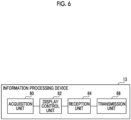
Fig. 6 is a block diagram showing an example of a functional configuration of a third information processing device. -
Fig. 7 is a diagram showing an example of a display screen of the third information processing device. -
Fig. 8 is a block diagram showing an example of a functional configuration of a fourth information processing device. -
Fig. 9 is a diagram showing an example of a display screen of the fourth information processing device. -
Fig. 10 is a flowchart showing an example of a first diagnosis support processing. -
Fig. 11 is a flowchart showing an example of a second diagnosis support processing. -
Fig. 12 is a flowchart showing an example of a third diagnosis support processing. -
Fig. 13 is a flowchart showing an example of a fourth diagnosis support processing. -
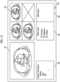
Fig. 14 is a diagram showing an example of a display screen of a second information processing device according to a modification example. - Hereinafter, an example of an embodiment of the technology of the present disclosure will be described in detail with reference to the drawings.
- First, a configuration of an
information processing system 10 according to the present embodiment will be described with reference toFig. 1 . As shown inFig. 1 , theinformation processing system 10 includes aninformation processing device 11, aninformation processing device 12, aninformation processing device 13, aninformation processing device 14, animage storage system 15, and a sharedserver 16. Theinformation processing device 11, theinformation processing device 12, theinformation processing device 14, theimage storage system 15, and the sharedserver 16 are installed in a facility called an Artificial Intelligence (AI) center, which mainly performs diagnosis of medical images through a computer. Theinformation processing device 13 is installed in a facility called an image center, which mainly interprets medical images. Theinformation processing device 11, theinformation processing device 12, theinformation processing device 13, theinformation processing device 14, theimage storage system 15, and the sharedserver 16 are each connected to a network and can communicate with each other. - The
information processing device 11 is a first information processing device for diagnosis of a medical image performed by a computer, such as CAD. Theinformation processing device 12 is a second information processing device for an imaging technician who captures the medical image, such as a radiographer. Theinformation processing device 13 is a third information processing device for an image interpreter who interprets the medical image, such as an image interpretation doctor. Theinformation processing device 14 is a fourth information processing device for a diagnostician who performs a comprehensive diagnosis of a patient, such as a general diagnostician. Examples of theinformation processing devices 11 to 14 include a computer, such as a personal computer or a server computer. - The
image storage system 15 is a system that stores image data showing a medical image captured by an imaging device which captures the medical image. Theimage storage system 15 transmits the image data corresponding to requests from theinformation processing devices 11 to 14 and the like to the request source device. Examples of theimage storage system 15 include a Picture Archiving and Communication Systems (PACS). Examples of medical images include a CT image captured by a Computed Tomography (CT) device, an MRI image captured by Magnetic Resonance Imaging (MRI), a radiation image captured by a Flat Panel Detector (FPD), and an endoscopic image captured by an endoscope system. In the present embodiment, an example in which a plurality of tomographic images captured by a CT device are applied as medical images to be diagnosed will be described. - The shared
server 16 has a storage device that stores information added by theinformation processing devices 11 to 14 to the medical image. The medical image stored in theimage storage system 15 and the information added to the medical image and stored in the sharedserver 16 are associated with each other by, for example, identification information, such as a patient IDentifier (ID) and an examination ID. - Next, a hardware configuration of the
information processing device 11 according to the present embodiment will be described with reference toFig. 2 . Since hardware configurations of theinformation processing devices 12 to 14 are the same as the hardware configuration of theinformation processing device 11, the description thereof will be omitted. As shown inFig. 2 , theinformation processing device 11 includes a central processing unit (CPU) 20, amemory 21 serving as a temporary storage area, and anon-volatile storage unit 22. In addition, theinformation processing device 11 includes adisplay 23, such as a liquid crystal display, aninput device 24, such as a keyboard and a mouse, and a network interface (I/F) 25 connected to a network. TheCPU 20, thememory 21, thestorage unit 22, thedisplay 23, theinput device 24, and the network I/F 25 are connected to abus 27. - The
storage unit 22 is realized by a hard disk drive (HDD), a solid state drive (SSD), a flash memory, or the like. Aninformation processing program 30 is stored in thestorage unit 22 serving as a storage medium. TheCPU 20 reads out theinformation processing program 30 from thestorage unit 22 and then develops the read-outinformation processing program 30 into thememory 21, and executes the developedinformation processing program 30. - Next, a functional configuration of the
information processing device 11 according to the present embodiment will be described with reference toFig. 3 . As shown inFig. 3 , theinformation processing device 11 includes anacquisition unit 40, adetection unit 42, and atransmission unit 44. TheCPU 20 of theinformation processing device 11 executes theinformation processing program 30 to function as theacquisition unit 40, thedetection unit 42, and thetransmission unit 44. - The
acquisition unit 40 acquires the medical image to be diagnosed from theimage storage system 15 via the network I/F 25. Thedetection unit 42 executes lesion detection processing on the medical image acquired by theacquisition unit 40. For example, thedetection unit 42 executes the lesion detection processing on the medical image by using a known CAD lesion detection algorithm. This algorithm is prepared in advance according to, for example, an imaging site and a type of lesion to be detected. In addition, in the lesion detection processing according to the present embodiment, a lesion having a size equal to or larger than a threshold value set in advance is detected. In this case, the threshold value is set in advance according to, for example, the imaging site and the type of lesion to be detected. - The
detection unit 42 may execute the lesion detection processing on the medical image by using a detection model obtained by machine learning, such as deep learning. Alternatively, thedetection unit 42 may execute the lesion detection processing on the medical image through filtering processing using a filter for detecting the lesion. - The
transmission unit 44 transmits an execution result of the lesion detection processing performed by the detection unit 42 (hereinafter, referred to as "lesion detection result") to the sharedserver 16 via the network I/F 25. The sharedserver 16 stores the lesion detection result transmitted from theinformation processing device 11. In a case where a lesion is detected by thedetection unit 42, the lesion detection result includes information indicating the detected lesion. Examples of the information indicating the lesion include a type of the lesion, a position of the lesion in the medical image, and a size of the lesion. On the other hand, in a case where the lesion is not detected by thedetection unit 42, the lesion detection result includes information indicating that the lesion is not detected. Thetransmission unit 44 may transmit the lesion detection result to theinformation processing device 12 via the network I/F 25. - Next, a functional configuration of the
information processing device 12 according to the present embodiment will be described with reference toFig. 4 . As shown inFig. 4 , theinformation processing device 12 includes anacquisition unit 50, adisplay control unit 52, areception unit 54, and atransmission unit 56. TheCPU 20 of theinformation processing device 12 executes theinformation processing program 30 to function as theacquisition unit 50, thedisplay control unit 52, thereception unit 54, and thetransmission unit 56. - The
acquisition unit 50 acquires the medical image to be diagnosed from theimage storage system 15 via the network I/F 25. In addition, theacquisition unit 50 acquires the lesion detection result corresponding to the medical image to be diagnosed from the sharedserver 16 via the network I/F 25. - The
display control unit 52 performs control to display the medical image and the lesion detection result, which are acquired by theacquisition unit 50, on thedisplay 23.Fig. 5 shows an example of a first display screen displayed on thedisplay 23 of theinformation processing device 12 by this control. - As shown in
Fig. 5 , the first display screen includes a display region A1 for a medical image, a display region A2 for patient information, a display region A3 for a lesion detection result, and a display region A4 for an input field of the first input information of the imaging technician. The medical image to be diagnosed acquired by theacquisition unit 50 is displayed on the display region A1. A tomographic position of the medical image first displayed on the display region A1 is set in advance, and the imaging technician can switch the medical image displayed on the display region A1 by scrolling a mouse wheel or the like. - Patient information, such as the name, the age, and the ID of the patient, is displayed on the display region A2. In a case where a lesion is detected by the
information processing device 11, the lesion is displayed on the display region A3 in a distinguishable manner. In this case, for example, the medical image in which the lesion is detected is displayed on the display region A3 in a state in which a frame line of the detected lesion is colored.Fig. 5 shows an example in which lesions are detected from three medical images and frame lines of the detected lesions are indicated by broken lines. Further, in a case where a lesion is not detected by theinformation processing device 11, information indicating that no lesion is detected is displayed on the display region A3. In this case, for example, a message, such as "No lesion is detected" is displayed on the display region A3. - The display region A4 includes a display region A5 for an input field of information indicating whether to approve or disapprove the lesion detection result, and a display region A6 for an input field of an additional report. In a case where the imaging technician approves the lesion detection result by referring to the display region A3, the imaging technician inputs information indicating approval of the lesion detection result by putting a checkmark in a "Positive" check box on the display region A5 via the
input device 24. On the other hand, in a case where the imaging technician disapproves the lesion detection result by referring to the display region A3, the imaging technician inputs information indicating disapproval of the lesion detection result by putting a checkmark in a "Negative" check box on the display region A5 via theinput device 24. This information input via the display region A5 is an example of the first input information. - Further, in a case where a non-detected lesion which is not included in the lesion detection result is found in the medical image, the imaging technician inputs information indicating the non-detected lesion as the first input information via the
input device 24. For example, the imaging technician traces an outer frame of the found lesion in the medical image displayed on the display region A1 to input information indicating the position and the size of the lesion, and inputs information indicating the type of the lesion into the display region A6. In addition, in a case where there is additional information to be input in the display region A6, the imaging technician inputs the information. - The
reception unit 54 receives the first input information of the imaging technician for the lesion detection result input as described above. Thetransmission unit 56 transmits the first input information received by thereception unit 54 to the sharedserver 16 via the network I/F 25. The sharedserver 16 stores the first input information transmitted from theinformation processing device 12. Thetransmission unit 56 may transmit the first input information to theinformation processing device 13 via the network I/F 25. - Next, a functional configuration of the
information processing device 13 according to the present embodiment will be described with reference toFig. 6 . As shown inFig. 6 , theinformation processing device 13 includes anacquisition unit 60, adisplay control unit 62, areception unit 64, and atransmission unit 66. TheCPU 20 of theinformation processing device 13 executes theinformation processing program 30 to function as theacquisition unit 60, thedisplay control unit 62, thereception unit 64, and thetransmission unit 66. - The
acquisition unit 60 acquires the medical image to be diagnosed from theimage storage system 15 via the network I/F 25. In addition, theacquisition unit 60 acquires the lesion detection result and the first input information corresponding to the medical image to be diagnosed from the sharedserver 16 via the network I/F 25. - The
display control unit 62 performs control to display the medical image, the lesion detection result, and the first input information, which are acquired by theacquisition unit 60, on thedisplay 23.Fig. 7 shows an example of a second display screen displayed on thedisplay 23 of theinformation processing device 13 by this control. - As shown in
Fig. 7 , the second display screen includes a display region B1 for a medical image, a display region B2 for patient information, a display region B3 for a lesion detection result, a display region B4 for an input field of the second input information of the image interpreter, and a display region B7 for the first input information. The display region B4 includes a display region B5 for an input field of information indicating whether to approve or disapprove the lesion detection result, and a display region B6 for an input field of an additional report. Since the display regions B1 to B6 are the same display regions as the display regions A1 to A6, the description thereof will be omitted here. - The display region B7 includes a display region B8 for information indicating whether the imaging technician has approved or disapproved the lesion detection result, and a display region B9 for a lesion that is not included in the lesion detection result and that is found and input as the first input information by the imaging technician.
Fig. 7 shows an example in which the lesion detection result is displayed in an upper part of the display region B8 and a checkmark is put on "Positive" in a lower part, that is, an example in which the imaging technician has approved the lesion detection result. Further, in the example ofFig. 7 , the lesion found by the imaging technician is displayed in an upper part of the display region B9, and an input field to which information indicating whether the image interpreter approves or disapproves the lesion found by the imaging technician is input is provided in a lower part. - In a case where the image interpreter approves the lesion detection result by referring to the display region B3, the image interpreter inputs information indicating approval of the lesion detection result by putting a checkmark in a "Positive" check box on the display region B5 via the
input device 24. On the other hand, in a case where the image interpreter disapproves the lesion detection result by referring to the display region B3, the image interpreter inputs information indicating disapproval of the lesion detection result by putting a checkmark in a "Negative" check box on the display region B5 via theinput device 24. This information input via the display region B5 is an example of the second input information. - Further, in a case where a non-detected lesion which is not included in the execution result and in the first input information is found in the medical image, the image interpreter inputs information indicating the non-detected lesion as the second input information via the
input device 24. For example, the image interpreter traces an outer frame of the found lesion in the medical image displayed on the display region B1 to input information indicating the position and the size of the lesion, and inputs information indicating the type of the lesion into the display region B6. In addition, in a case where there is additional information to be input in the display region B6, the image interpreter inputs the information. - In addition, in a case where the image interpreter approves the lesion found by the imaging technician and included in the first input information, the image interpreter inputs information indicating approval of the first input information by putting a checkmark in a "Positive" check box on the display region B9 via the
input device 24. On the other hand, in a case where the image interpreter disapproves the lesion found by the imaging technician and included in the first input information, the image interpreter inputs information indicating disapproval of the first input information by putting a checkmark in a "Negative" check box on the display region B9 via theinput device 24. This information input via the display region B9 is also an example of the second input information. - The
reception unit 64 receives the lesion detection result and the second input information of the image interpreter for the first input information, which are input as described above. Thetransmission unit 66 transmits the second input information received by thereception unit 64 to the sharedserver 16 via the network I/F 25. The sharedserver 16 stores the second input information transmitted from theinformation processing device 13. Thetransmission unit 66 may transmit the second input information to theinformation processing device 14 via the network I/F 25. - Next, a functional configuration of the
information processing device 14 according to the present embodiment will be described with reference toFig. 8 . As shown inFig. 8 , theinformation processing device 14 includes anacquisition unit 70, adisplay control unit 72, areception unit 74, and atransmission unit 76. TheCPU 20 of theinformation processing device 14 executes theinformation processing program 30 to function as theacquisition unit 70, thedisplay control unit 72, thereception unit 74, and thetransmission unit 76. - The
acquisition unit 70 acquires the medical image to be diagnosed from theimage storage system 15 via the network I/F 25. In addition, theacquisition unit 70 acquires the lesion detection result and the second input information corresponding to the medical image to be diagnosed from the sharedserver 16 via the network I/F 25. - The
display control unit 72 performs control to display the medical image, the lesion detection result, and the second input information, which are acquired by theacquisition unit 70, on thedisplay 23.Fig. 9 shows an example of a third display screen displayed on thedisplay 23 of theinformation processing device 14 by this control. - As shown in
Fig. 9 , the third display screen includes a display region C1 for a medical image, a display region C2 for patient information, a display region C3 for a lesion detection result, a display region C4 for an input field of the comprehensive diagnosis result of the diagnostician, and a display region C7 for the second input information. The display region C4 includes a display region C5 for an input field of information indicating whether to approve or disapprove the lesion detection result, and a display region C6 for an input field of an additional report. Since the display regions C1 to C6 are the same display regions as the display regions B 1 to B6, the description thereof will be omitted here. - The display region C7 includes a display region C8 for information indicating whether the image interpreter has approved or disapproved the lesion detection result, and a display region C9 for a lesion that is not included in the lesion detection result and that is found and input as the second input information by the image interpreter.
Fig. 9 shows an example in which the lesion detection result is displayed in an upper part of the display region C8 and a checkmark is put on "Positive" in a lower part, that is, an example in which the image interpreter has approved the lesion detection result. Further, in the example ofFig. 9 , the lesion found by the image interpreter is displayed in an upper part of the display region C9, and an input field to which information indicating whether the diagnostician approves or disapproves the lesion found by the image interpreter is input is provided in a lower part. - In a case where the diagnostician approves the lesion detection result by referring to the display region C3, the diagnostician inputs information indicating approval of the lesion detection result by putting a checkmark in a "Positive" check box on the display region C5 via the
input device 24. On the other hand, in a case where the diagnostician disapproves the lesion detection result by referring to the display region C3, the diagnostician inputs information indicating disapproval of the lesion detection result by putting a checkmark in a "Negative" check box on the display region C5 via theinput device 24. - Further, in a case where a non-detected lesion which is not included in the execution result and in the second input information is found in the medical image, the diagnostician inputs information indicating the non-detected lesion via the
input device 24. For example, the diagnostician traces an outer frame of the found lesion in the medical image displayed on the display region C1 to input information indicating the position and the size of the lesion, and inputs information indicating the type of the lesion into the display region C6. - In addition, in a case where the diagnostician approves the lesion found by the image interpreter and included in the second input information, the diagnostician inputs information indicating approval of the second input information by putting a checkmark in a "Positive" check box on the display region C9 via the
input device 24. On the other hand, in a case where the diagnostician disapproves the lesion found by the image interpreter and included in the second input information, the diagnostician inputs information indicating disapproval of the second input information by putting a checkmark in a "Negative" check box on the display region C9 via theinput device 24. - In addition, the diagnostician inputs the comprehensive diagnosis result to the display region C6 via the
input device 24. Examples of the comprehensive diagnosis result include a comprehensive diagnosis result related to a patient, which is obtained through interpretation of the medical image, such as a message saying "Since there is a suspicion of disease A, please consult at hospital B" and a message saying "There is no particular problem". - The
reception unit 74 receives various types of information including the comprehensive diagnosis result input as described above. Thetransmission unit 76 transmits various types of information including the comprehensive diagnosis result received by thereception unit 74 to the sharedserver 16 via the network I/F 25. The sharedserver 16 stores the information transmitted from theinformation processing device 14. In other words, thetransmission unit 76 stores the comprehensive diagnosis result received by thereception unit 74 in the sharedserver 16. - Next, an action of the
information processing system 10 according to the present embodiment will be described with reference toFigs. 10 to 13 . TheCPU 20 of theinformation processing device 11 executes theinformation processing program 30, whereby first diagnosis support processing shown inFig. 10 is executed. The first diagnosis support processing shown inFig. 10 is executed, for example, in a case where an instruction to start execution is input by the imaging technician via theinput device 24. - In addition, the
CPU 20 of theinformation processing device 12 executes theinformation processing program 30, whereby second diagnosis support processing shown inFig. 11 is executed. The second diagnosis support processing shown inFig. 11 is executed, for example, in a case where an instruction to start execution is input by the imaging technician via theinput device 24. Further, theCPU 20 of theinformation processing device 13 executes theinformation processing program 30, whereby third diagnosis support processing shown inFig. 12 is executed. The third diagnosis support processing shown inFig. 12 is executed, for example, in a case where an instruction to start execution is input by the image interpreter via theinput device 24. Further, theCPU 20 of theinformation processing device 14 executes theinformation processing program 30, whereby fourth diagnosis support processing shown inFig. 13 is executed. The fourth diagnosis support processing shown inFig. 13 is executed, for example, in a case where an instruction to start execution is input by the diagnostician via theinput device 24. - In step S10 of
Fig. 10 , theacquisition unit 40 acquires the medical image to be diagnosed from theimage storage system 15 via the network I/F 25. Instep S 12, thedetection unit 42 executes the lesion detection processing on the medical image acquired in step S10. In step S14, thetransmission unit 44 transmits the lesion detection result obtained by the processing of step S12 to the sharedserver 16 via the network I/F 25. In a case where the processing of step S14 ends, the first diagnosis support processing ends. - In step S20 of
Fig. 11 , theacquisition unit 50 acquires the medical image to be diagnosed from theimage storage system 15 via the network I/F 25. In addition, theacquisition unit 50 acquires the lesion detection result corresponding to the medical image to be diagnosed from the sharedserver 16 via the network I/F 25. - In step S22, the
display control unit 52 performs control to display the medical image and the lesion detection result, which are acquired in step S20, on thedisplay 23. In step S24, as described above, thereception unit 54 receives the first input information of the imaging technician for the lesion detection result, which is input via the first display screen (seeFig. 5 ) displayed on thedisplay 23 by the processing of step S22. In step S26, thetransmission unit 56 transmits the first input information received in step S24 to the sharedserver 16 via the network I/F 25. In a case where the processing of step S26 ends, the second diagnosis support processing ends. - In step S30 of
Fig. 12 , theacquisition unit 60 acquires the medical image to be diagnosed from theimage storage system 15 via the network I/F 25. In addition, theacquisition unit 60 acquires the lesion detection result and the first input information corresponding to the medical image to be diagnosed from the sharedserver 16 via the network I/F 25. - In step S32, the
display control unit 62 performs control to display the medical image, the lesion detection result, and the first input information, which are acquired in step S30, on thedisplay 23. In step S34, as described above, thereception unit 54 receives the lesion detection result and the second input information of the image interpreter for the first input information, which are input via the second display screen (seeFig. 7 ) displayed on thedisplay 23 by the processing of step S32. In step S36, thetransmission unit 66 transmits the second input information received in step S34 to the sharedserver 16 via the network I/F 25. In a case where the processing of step S36 ends, the third diagnosis support processing ends. - In step S40 of
Fig. 13 , theacquisition unit 70 acquires the medical image to be diagnosed from theimage storage system 15 via the network I/F 25. In addition, theacquisition unit 70 acquires the lesion detection result and the second input information corresponding to the medical image to be diagnosed from the sharedserver 16 via the network I/F 25. - In step S42, the
display control unit 72 performs control to display the medical image, the lesion detection result, and the second input information, which are acquired in step S40, on thedisplay 23. In step S44, as described above, thereception unit 74 receives various types of information including the comprehensive diagnosis result, which is input via the third display screen (seeFig. 9 ) displayed on thedisplay 23 by the processing of step S42. In step S46, thetransmission unit 76 transmits the various types of information including the comprehensive diagnosis result, which is received in step S44, to the sharedserver 16 via the network I/F 25. In a case where the processing of step S46 ends, the fourth diagnosis support processing ends. - As described above, according to the present embodiment, a flow is realized in which the imaging technician, the image interpreter, and the diagnostician perform only a simple confirmation for the lesion detected by the computer and intensively confirm a region in which nothing is detected in the medical image by the computer. Accordingly, it is possible to improve the efficiency of diagnosis using the CAD result performed by three parties, that is, the imaging technician, the image interpreter, and the diagnostician.
- In the above-described embodiment, an aspect may be employed in which information indicating deletion of the lesion included in the lesion detection result is applied as the first input information and as the second input information. In this case, as shown in
Fig. 14 as an example, the imaging technician inputs information indicating the deletion of the lesion included in the lesion detection result by putting a checkmark in a "Delete" check box on the display region A5 via theinput device 24. Further, in this case, the sharedserver 16 deletes the information indicating the lesion from the lesion detection result. - In addition, in the above-described embodiment, the
display control unit 72 may perform control to display the first input information on thedisplay 23 in addition to the medical image and the second input information. In this case, for example, the same display region as the display region B9 on the second display screen is provided on the third display screen. - In addition, in the above-described embodiment, in a case where the lesion detection result includes information indicating one or more lesions, the
display control unit 52, thedisplay control unit 62, and thedisplay control unit 72 may perform control to display the medical image to be diagnosed in a state in which the number of medical images is reduced, when displaying the medical image. In this case, for example, thedisplay control unit 52, thedisplay control unit 62, and thedisplay control unit 72 perform control to display a tomographic image every other image when switching the display of the tomographic image, thereby halving the number of displayed medical images. - Further, in the above-described embodiment, for example, various processors shown below can be used as the hardware structure of a processing unit that executes various types of processing, such as each functional unit of the
information processing devices 11 to 14. The above-described various processors include, for example, a programmable logic device (PLD) which is a processor having a changeable circuit configuration after manufacture, such as a field programmable gate array (FPGA), and a dedicated electrical circuit which is a processor having a dedicated circuit configuration designed for executing specific processing, such as an application specific integrated circuit (ASIC), in addition to the CPU which is a general-purpose processor that executes software (programs) to function as various processing units, as described above. - One processing unit may be composed of one of these various processors or a combination of two or more processors of the same type or different types (for example, a combination of a plurality of FPGAs or a combination of a CPU and an FPGA). Alternatively, a plurality of processing units may be composed of one processor.
- A first example in which a plurality of processing units are composed of one processor is an aspect in which one or more CPUs and software are combined to constitute one processor and the processor functions as the plurality of processing units, as typified by a computer, such as a client and a server. A second example is an aspect in which a processor that realizes all the functions of a system including a plurality of processing units with one integrated circuit (IC) chip is used, as typified by a system on chip (SoC). As described above, various processing units are composed of one or more of the above-described various processors as the hardware structure.
- Further, as the hardware structure of these various processors, more specifically, an electrical circuit (circuitry) in which circuit elements, such as semiconductor elements, are combined can be used.
- In the above-described embodiment, an aspect in which the
information processing program 30 is stored (installed) in advance in thestorage unit 22 has been described, but the present disclosure is not limited thereto. Theinformation processing program 30 may be provided in a form of being recorded on a recording medium, such as a compact disc read only memory (CD-ROM), a digital versatile disc read only memory (DVD-ROM), and a Universal Serial Bus (USB) memory. Alternatively, theinformation processing program 30 may be downloaded from an external device via the network. -
- 10: information processing system
- 11, 12, 13, 14: information processing device
- 15: image storage system
- 16: shared server
- 20: CPU
- 21: memory
- 22: storage unit
- 23: display
- 24: input device
- 25: network I/F
- 27: bus
- 30: information processing program
- 40, 50, 60, 70: acquisition unit
- 42: detection unit
- 44, 56, 66, 76: transmission unit
- 52, 62, 72: display control unit
- 54, 64, 74: reception unit
- A1 to A6, B1 to B9, C1 to C9: display region
Claims (10)
- An information processing system comprising:a first information processing device for diagnosis of a medical image performed by a computer;a second information processing device for an imaging technician who captures the medical image;a third information processing device for an image interpreter who interprets the medical image; anda fourth information processing device for a diagnostician who performs a comprehensive diagnosis of a patient,wherein each of the first information processing device, the second information processing device, the third information processing device, and the fourth information processing device includes at least one processor,the processor of the first information processing device is configured toacquire a medical image to be diagnosed,execute lesion detection processing on the acquired medical image, andtransmit an execution result of the lesion detection processing,the processor of the second information processing device is configured toperform control to display the medical image and the execution result,receive first input information of the imaging technician for the execution result, andtransmit the first input information,the processor of the third information processing device is configured toperform control to display the medical image, the execution result, and the first input information,receive second input information of the image interpreter for the execution result, andtransmit the second input information, andthe processor of the fourth information processing device is configured toperform control to display the medical image, the execution result, and the second input information,receive a comprehensive diagnosis result of the diagnostician, andstore the diagnosis result.
- The information processing system according to claim 1,
wherein the first input information is information indicating whether to approve or disapprove the execution result. - The information processing system according to claim 1 or 2,
wherein the first input information is information indicating a non-detected lesion that is not included in the execution result. - The information processing system according to any one of claims 1 to 3,
wherein the first input information is information indicating deletion of a lesion included in the execution result. - The information processing system according to any one of claims 1 to 4,
wherein the second input information is information indicating whether to approve or disapprove the execution result and the first input information. - The information processing system according to any one of claims 1 to 5,
wherein the second input information is information indicating a non-detected lesion that is not included in the execution result and in the first input information. - The information processing system according to any one of claims 1 to 6,
wherein the processor of the fourth information processing device is configured to
perform control to display the first input information in addition to the medical image and the second input information. - The information processing system according to any one of claims 1 to 7,wherein there are a plurality of the medical images to be diagnosed, andthe processors of the second information processing device, of the third information processing device, and of the fourth information processing device are configured to
perform, in a case where the execution result includes information indicating one or more lesions, control to display the medical image in a state in which the number of medical images is reduced, when displaying the medical image to be diagnosed. - An information processing method using an information processing system including a first information processing device for diagnosis of a medical image performed by a computer, a second information processing device for an imaging technician who captures the medical image, a third information processing device for an image interpreter who interprets the medical image, and a fourth information processing device for a diagnostician who performs a comprehensive diagnosis of a patient, the information processing method comprising:causing a processor provided in the first information processing device toacquire a medical image to be diagnosed,execute lesion detection processing on the acquired medical image, andtransmit an execution result of the lesion detection processing;causing a processor provided in the second information processing device toperform control to display the medical image and the execution result,receive first input information of the imaging technician for the execution result, andtransmit the first input information;causing a processor provided in the third information processing device toperform control to display the medical image, the execution result, and the first input information,receive second input information of the image interpreter for the execution result, andtransmit the second input information; andcausing a processor provided in the fourth information processing device toperform control to display the medical image, the execution result, and the second input information,receive a comprehensive diagnosis result of the diagnostician, andstore the diagnosis result.
- An information processing program in an information processing system including a first information processing device for diagnosis of a medical image performed by a computer, a second information processing device for an imaging technician who captures the medical image, a third information processing device for an image interpreter who interprets the medical image, and a fourth information processing device for a diagnostician who performs a comprehensive diagnosis of a patient,the information processing program causing a processor provided in the first information processing device to execute processing of:acquiring a medical image to be diagnosed;executing lesion detection processing on the acquired medical image; andtransmitting an execution result of the lesion detection processing,causing a processor provided in the second information processing device to execute processing of:performing control to display the medical image and the execution result;receiving first input information of the imaging technician for the execution result; andtransmitting the first input information,causing a processor provided in the third information processing device to execute processing of:performing control to display the medical image, the execution result, and the first input information;receiving second input information of the image interpreter for the execution result; andtransmitting the second input information, andcausing a processor provided in a processor of the fourth information processing device to execute processing of:performing control to display the medical image, the execution result, and the second input information;receiving a comprehensive diagnosis result of the diagnostician; andstoring the diagnosis result.
Applications Claiming Priority (2)
| Application Number | Priority Date | Filing Date | Title |
|---|---|---|---|
| JP2020162701 | 2020-09-28 | ||
| PCT/JP2021/028137 WO2022064838A1 (en) | 2020-09-28 | 2021-07-29 | Information processing system, information processing method, and information processing program |
Publications (2)
| Publication Number | Publication Date |
|---|---|
| EP4220656A1 true EP4220656A1 (en) | 2023-08-02 |
| EP4220656A4 EP4220656A4 (en) | 2024-03-20 |
Family
ID=80845259
Family Applications (1)
| Application Number | Title | Priority Date | Filing Date |
|---|---|---|---|
| EP21871970.6A Pending EP4220656A4 (en) | 2020-09-28 | 2021-07-29 | INFORMATION PROCESSING SYSTEM, INFORMATION PROCESSING METHOD AND INFORMATION PROCESSING PROGRAM |
Country Status (5)
| Country | Link |
|---|---|
| US (1) | US20230230246A1 (en) |
| EP (1) | EP4220656A4 (en) |
| JP (1) | JP7404555B2 (en) |
| CN (1) | CN116210056B (en) |
| WO (1) | WO2022064838A1 (en) |
Families Citing this family (1)
| Publication number | Priority date | Publication date | Assignee | Title |
|---|---|---|---|---|
| JP2024086186A (en) * | 2022-12-16 | 2024-06-27 | キヤノン株式会社 | Radiography apparatus and control method thereof, radiation imaging system, information processing apparatus, and program |
Family Cites Families (13)
| Publication number | Priority date | Publication date | Assignee | Title |
|---|---|---|---|---|
| JPH06251038A (en) | 1993-03-01 | 1994-09-09 | Toshiba Corp | Medical diagnosis support system |
| US20040120558A1 (en) * | 2002-12-18 | 2004-06-24 | Sabol John M | Computer assisted data reconciliation method and apparatus |
| JP4218347B2 (en) | 2003-01-17 | 2009-02-04 | コニカミノルタホールディングス株式会社 | Diagnostic imaging support device |
| CA2610345C (en) * | 2005-06-02 | 2013-12-24 | The Medipattern Corporation | System and method of computer-aided detection |
| JP2007330514A (en) * | 2006-06-15 | 2007-12-27 | Fujifilm Corp | Medical image diagnosis support system |
| US8989458B2 (en) * | 2007-10-17 | 2015-03-24 | Kabushiki Kaisha Toshiba | Image diagnosis support system and image diagnosis support method |
| JP2011103095A (en) | 2009-11-12 | 2011-05-26 | Konica Minolta Medical & Graphic Inc | Medical image display system and program |
| JP5677807B2 (en) * | 2010-11-04 | 2015-02-25 | 株式会社日立メディコ | Medical image display apparatus and method and program thereof |
| JP5762597B2 (en) * | 2014-05-07 | 2015-08-12 | キヤノン株式会社 | Radiation imaging control apparatus, control method thereof, and program |
| JP6448588B2 (en) * | 2016-08-25 | 2019-01-09 | キヤノン株式会社 | Medical diagnosis support apparatus, medical diagnosis support system, information processing method, and program |
| WO2019146357A1 (en) * | 2018-01-24 | 2019-08-01 | 富士フイルム株式会社 | Medical image processing device, method, and program, and diagnosis assistance device, method, and program |
| CN108478288A (en) * | 2018-04-13 | 2018-09-04 | 温州医科大学附属第医院 | Tripartite verifies the control system of combination anesthesia information system in a kind of operation |
| JP6646717B2 (en) * | 2018-09-03 | 2020-02-14 | キヤノン株式会社 | Medical document creation device, control method therefor, and program |
-
2021
- 2021-07-29 CN CN202180064424.2A patent/CN116210056B/en active Active
- 2021-07-29 EP EP21871970.6A patent/EP4220656A4/en active Pending
- 2021-07-29 JP JP2022551166A patent/JP7404555B2/en active Active
- 2021-07-29 WO PCT/JP2021/028137 patent/WO2022064838A1/en not_active Ceased
-
2023
- 2023-03-21 US US18/186,950 patent/US20230230246A1/en not_active Abandoned
Also Published As
| Publication number | Publication date |
|---|---|
| US20230230246A1 (en) | 2023-07-20 |
| WO2022064838A1 (en) | 2022-03-31 |
| EP4220656A4 (en) | 2024-03-20 |
| JP7404555B2 (en) | 2023-12-25 |
| CN116210056A (en) | 2023-06-02 |
| JPWO2022064838A1 (en) | 2022-03-31 |
| CN116210056B (en) | 2025-10-21 |
Similar Documents
| Publication | Publication Date | Title |
|---|---|---|
| US11139067B2 (en) | Medical image display device, method, and program | |
| US11875897B2 (en) | Medical image processing apparatus, method, and program, and diagnosis support apparatus, method, and program | |
| CN111816285B (en) | Medical information processing device and medical information processing method | |
| JP7129869B2 (en) | Disease area extraction device, method and program | |
| US20190189270A1 (en) | Hospital information apparatus, hospital information system, and hospital information processing method | |
| CN113327665B (en) | Medical information processing system and medical information processing method | |
| US11574402B2 (en) | Inspection information display device, method, and program | |
| JP2019109810A (en) | Interpretation report analysis device and program | |
| US20230230246A1 (en) | Information processing system, information processing method, and information processing program | |
| US20190095583A1 (en) | Method and system for electronic medical record processing in presence of conflicts | |
| JP2012143368A (en) | Medical image display device and program | |
| JP6966403B2 (en) | Diagnostic support device | |
| JP2020154630A (en) | Medical information collection device | |
| JP2020086730A (en) | Priority determination device, method and program | |
| JP6711675B2 (en) | Interpretation support device | |
| US12423809B2 (en) | Medical image processing apparatus, method, and program for detecting abnormal region by setting threshold | |
| US11238976B2 (en) | Interpretation support apparatus and non-transitory computer readable medium | |
| JP2021140757A (en) | Medical information processing system, medical information processing method, and medical information processing program | |
| US12307662B2 (en) | Information processing system, information processing method, and information processing program | |
| WO2020066115A1 (en) | Medical image display device, method, and program | |
| US12217867B2 (en) | Medical information processing system and medical information processing apparatus | |
| JP2025017450A (en) | Processing device, processing program, processing method, and processing system | |
| JP5533198B2 (en) | Medical image display apparatus and program | |
| US20150145779A1 (en) | Image Display Apparatus And Image Display Method | |
| US20250195021A1 (en) | Medical image display apparatus, medical image display system, storage medium, and medical image display method |
Legal Events
| Date | Code | Title | Description |
|---|---|---|---|
| STAA | Information on the status of an ep patent application or granted ep patent |
Free format text: STATUS: THE INTERNATIONAL PUBLICATION HAS BEEN MADE |
|
| PUAI | Public reference made under article 153(3) epc to a published international application that has entered the european phase |
Free format text: ORIGINAL CODE: 0009012 |
|
| STAA | Information on the status of an ep patent application or granted ep patent |
Free format text: STATUS: REQUEST FOR EXAMINATION WAS MADE |
|
| 17P | Request for examination filed |
Effective date: 20230322 |
|
| AK | Designated contracting states |
Kind code of ref document: A1 Designated state(s): AL AT BE BG CH CY CZ DE DK EE ES FI FR GB GR HR HU IE IS IT LI LT LU LV MC MK MT NL NO PL PT RO RS SE SI SK SM TR |
|
| DAV | Request for validation of the european patent (deleted) | ||
| DAX | Request for extension of the european patent (deleted) | ||
| A4 | Supplementary search report drawn up and despatched |
Effective date: 20240220 |
|
| RIC1 | Information provided on ipc code assigned before grant |
Ipc: G16H 40/67 20180101ALI20240214BHEP Ipc: G16H 15/00 20180101ALI20240214BHEP Ipc: G09G 5/14 20060101ALI20240214BHEP Ipc: G06F 3/14 20060101ALI20240214BHEP Ipc: G16H 30/40 20180101ALI20240214BHEP Ipc: G16H 50/70 20180101ALI20240214BHEP Ipc: A61B 5/00 20060101ALI20240214BHEP Ipc: G16H 50/20 20180101ALI20240214BHEP Ipc: G16H 30/20 20180101AFI20240214BHEP |