EP4220610A1 - Display device - Google Patents
Display device Download PDFInfo
- Publication number
- EP4220610A1 EP4220610A1 EP20963081.3A EP20963081A EP4220610A1 EP 4220610 A1 EP4220610 A1 EP 4220610A1 EP 20963081 A EP20963081 A EP 20963081A EP 4220610 A1 EP4220610 A1 EP 4220610A1
- Authority
- EP
- European Patent Office
- Prior art keywords
- display screen
- flexible display
- adsorption
- housing
- display device
- Prior art date
- Legal status (The legal status is an assumption and is not a legal conclusion. Google has not performed a legal analysis and makes no representation as to the accuracy of the status listed.)
- Granted
Links
Images





Classifications
-
- G—PHYSICS
- G09—EDUCATION; CRYPTOGRAPHY; DISPLAY; ADVERTISING; SEALS
- G09F—DISPLAYING; ADVERTISING; SIGNS; LABELS OR NAME-PLATES; SEALS
- G09F9/00—Indicating arrangements for variable information in which the information is built-up on a support by selection or combination of individual elements
- G09F9/30—Indicating arrangements for variable information in which the information is built-up on a support by selection or combination of individual elements in which the desired character or characters are formed by combining individual elements
- G09F9/301—Indicating arrangements for variable information in which the information is built-up on a support by selection or combination of individual elements in which the desired character or characters are formed by combining individual elements flexible foldable or roll-able electronic displays, e.g. thin LCD, OLED
-
- H—ELECTRICITY
- H05—ELECTRIC TECHNIQUES NOT OTHERWISE PROVIDED FOR
- H05K—PRINTED CIRCUITS; CASINGS OR CONSTRUCTIONAL DETAILS OF ELECTRIC APPARATUS; MANUFACTURE OF ASSEMBLAGES OF ELECTRICAL COMPONENTS
- H05K5/00—Casings, cabinets or drawers for electric apparatus
- H05K5/02—Details
- H05K5/0217—Mechanical details of casings
-
- G—PHYSICS
- G06—COMPUTING OR CALCULATING; COUNTING
- G06F—ELECTRIC DIGITAL DATA PROCESSING
- G06F1/00—Details not covered by groups G06F3/00 - G06F13/00 and G06F21/00
- G06F1/16—Constructional details or arrangements
- G06F1/1601—Constructional details related to the housing of computer displays, e.g. of CRT monitors, of flat displays
-
- G—PHYSICS
- G06—COMPUTING OR CALCULATING; COUNTING
- G06F—ELECTRIC DIGITAL DATA PROCESSING
- G06F1/00—Details not covered by groups G06F3/00 - G06F13/00 and G06F21/00
- G06F1/16—Constructional details or arrangements
- G06F1/1613—Constructional details or arrangements for portable computers
- G06F1/1633—Constructional details or arrangements of portable computers not specific to the type of enclosures covered by groups G06F1/1615 - G06F1/1626
- G06F1/1637—Details related to the display arrangement, including those related to the mounting of the display in the housing
- G06F1/1652—Details related to the display arrangement, including those related to the mounting of the display in the housing the display being flexible, e.g. mimicking a sheet of paper, or rollable
Definitions
- the present application relates to the technical field of display, and particularly relates to a display device.
- the present application provides a display device, which may achieve an effect that a flexible display screen presents different curved shapes when being unrolled.
- a display device including:
- the display device includes the housing, the opening is provided on the surface of the housing, the reel is placed in the housing, and the flexible display screen is connected with the reel and is capable of being rolled around the reel or unrolled.
- the flexible display screen is accommodated in the housing, and when the flexible display screen is in an unrolled state, the terminal end of the flexible display screen is capable of extending out of the housing from the opening.
- the display screen adsorption plate is provided outside the housing, when the flexible display screen is in an unrolled state, the adsorption device may adsorb the flexible display screen so as to enable the flexible display screen to be attached to the display screen adsorption plate, so that the flexible display screen is capable of presenting the same shape as the display screen adsorption plate.
- the flexible display screen is enabled to be attached to the display screen adsorption plate when being unrolled, so that the flexible display screen may present different curved shapes when being unrolled, so as to fully embody a flexible aesthetic feeling.
- the display device provided by the present application may achieve the effect that the flexible display screen presents different curved shapes when being unrolled.
- the display device further includes a driving device installed in the accommodating space, and the driving device is configured to drive the reel to rotate around its own axis to drive the flexible display screen to be rolled or unrolled.
- the flexible display screen is in a rolled state, the flexible display screen is wound around a surface of the reel.
- the driving device includes a driving motor and a conveyor belt
- the reel is provided with a rotating shaft
- the driving motor is provided with a driving shaft
- the conveyor belt is connected with the rotating shaft and the driving shaft separately
- the driving shaft drives the rotating shaft to rotate around its own axis by the conveyor belt.
- a supporting structure is connected between the start end of the flexible display screen and the reel, and the supporting structure is in smooth and transitional connection with the start end.
- a thickness of the supporting structure is 60 ⁇ m-150 ⁇ m.
- the supporting structure is made of rubber.
- the adsorption device further includes a power device and a power connecting pipe that are located in the accommodating space;
- a thickness of the airflow cavity is 10 mm-12 mm.
- the air holes include a plurality of rows of air holes evenly arranged in an extension direction of the display screen adsorption plate, and each row of air holes includes a plurality of air holes.
- a diameter of each of the plurality of air holes is 6 mm-10 mm.
- the display screen adsorption plate has a first end closer to the housing and a second end farther from the housing, a distance between a center of an air hole in a row of air holes closest to the second end and the second end is 25 mm-35 mm, and a distance between a center of an air holes in a row of air holes closest to the first end and the first end is 15 mm-25 mm.
- the opening is provided with a guide surface, and the guide surface is in smooth and transitional connection with the adsorption surface.
- the display screen adsorption plate is made of a transparent acrylic plate.
- the fitting surface is provided with a polyethylene terephthalate (PET) protective film.
- PET polyethylene terephthalate
- the display screen adsorption plate is detachably installed on a surface of a side of the housing with the opening.
- a thickness of the flexible display screen is 100 ⁇ m-150 ⁇ m.
- the present application provides a display device, which includes: a housing 1, a reel 2, a flexible display screen 3, and an adsorption device 4.
- An accommodating space is provided inside the housing 1, and an opening 11 is provided on a surface of the housing 1.
- the reel 2 is located in the accommodating space and is capable of rotating around its own axis.
- the flexible display screen 3 has a start end 31 and a terminal end 32 opposite each other, and a display surface 33 and a fitting surface 34 opposite each other.
- the start end 31 of the flexible display screen 3 is connected with the reel 2, and the terminal end 32 is in a free state, so that the flexible display screen 3 is capable of being rolled around the reel 2 or unrolled.
- the adsorption device 4 includes a display screen adsorption plate 41 located outside the housing 1. When the flexible display screen 3 is in an unrolled state, the adsorption device 4 adsorbs the flexible display screen 3 so as to enable the fitting surface 34 to be attached to the display screen adsorption plate 41.
- the display device includes the housing 1, the opening 11 is provided on the surface of the housing 1, the reel 2 is placed in the housing 1, and the flexible display screen 3 is connected with the reel 2 and is capable of being rolled around the reel 2 or unrolled.
- the display screen 3 is accommodated in the housing 1, and when the flexible display screen 3 is in an unrolled state, the terminal end 32 of the flexible display screen 3 is capable of extending out of the housing 1 from the opening 11.
- the display screen adsorption plate 41 is provided outside the housing 1.
- the adsorption device 4 may adsorb the flexible display screen 3 so as to enable the flexible display screen to be attached to the display screen adsorption plate 41, so that the flexible display screen 3 is capable of presenting the same shape as the display screen adsorption plate 41.
- the display surface 33 is configured to display a picture normally.
- the flexible display screen 3 is enabled to be attached to the display screen adsorption plate 41 when being unrolled, so that the flexible display screen 3 may present different curved shapes when being unrolled, so as to fully embody a flexible aesthetic feeling.
- the display device provided by the present application may achieve an effect that the flexible display screen 3 presents different curved shapes when being unrolled.
- the flexible display screen 3 is accommodated in the housing 1 when being in a rolled state, such that the flexible display screen 3 may be protected and portable.
- the display surface 33 is capable of displaying a picture during rolling or unrolling movement of the flexible display screen 3.
- the display device further includes a driving device 5 installed in the accommodating space.
- the driving device is configured to drive the reel 2 to rotate around its own axis so as to drive the flexible display screen 3 to be rolled or unrolled, so that the flexible display screen 3 may be accommodated and unrolled.
- the flexible display screen 3 is wound around a surface of the reel 2 when being in a rolled state.
- the driving device 5 may include a motor 51 and a conveyor belt 52, the motor 51 is provided with a driving shaft, the reel 2 is provided with a rotating shaft, and the conveyor belt 52 is connected with the driving shaft and the rotating shaft separately, so that when the motor 51 works, the driving shaft transmits power to the conveyor belt 52, and the conveyor belt 52 may drive the rotating shaft to rotate.
- the reel 2 is capable of rotating around its own axis.
- the flexible display screen 3 may be automatically rolled and unrolled, such that the flexible display screen 3 has a smaller size after being rolled, and portability is improved.
- the driving device 5 when the driving device 5 drives the reel 2 to rotate so as to enable the flexible display screen 3 to be rolled or unrolled, the driving device 5 may be further configured to control a rolling length or an unrolling length of the flexible display screen 3.
- the rolling length or the unrolling length of the flexible display screen 3 may be controlled by the driving device 5 through a single chip microcomputer or programmable logic controller (PLC), a PLC program is set on the driving device 5 according to a size of the flexible display screen 3, and the driving device 5 is controlled to be turned on or off by automatically controlling and measuring the rolling length or the unrolling length of the flexible display screen 3, so that the flexible display screen 3 may be prevented from being damaged by excessive rolling or unrolling.
- PLC programmable logic controller
- Use requirements of the display device by different users in different scenes may be fully satisfied by controlling the rolling length or unrolling length of the flexible display screen 3, so that the display device is more convenient to use and more adaptable.
- a supporting structure 6 is connected between the start end 31 of the flexible display screen 3 and the reel 2, and the supporting structure 6 is in smooth and transitional connection with the start end 31 and is fixedly connected with the reel 2.
- the flexible display screen 3 may be prevented from being damaged by stress concentrated at the edge of the flexible display screen in a rolling process, so that the flexible display screen 3 may be smoother in the rolled state and unrolled state.
- the supporting structure 6 may be preferably made of rubber or other elastic materials, and a thickness of the supporting structure may be 60 ⁇ m-150 ⁇ m, so that the flexible display screen 3 is better prevented from being damaged by the stress concentrated at the edge of the flexible display screen in a rolling process.
- the adsorption device 4 in the present application further includes a power device 42 and a power connecting pipe 43 that are located in the accommodating space. Meanwhile, a hollow structure is provided inside the display screen adsorption plate 41 to form an airflow cavity 411 in communication with the power connecting pipe 43, and the adsorption surface 413, configured to be attached to the flexible display screen 3, of the display screen adsorption plate 41 is provided with a plurality of air holes 412 in communication with the airflow cavity 411.
- the power device 42 is configured to be connected with the power connecting pipe 43, and form adsorption air pressure at the air holes 412 on the adsorption surface 413 through airflow changes in the airflow cavity 411 when the power connecting pipe 43 is in communication with the airflow cavity 411. In this way, the flexible display screen 3 is completely attached to the display screen adsorption plate.
- the power device 42 may control airflow in the airflow cavity 411 according to a size of the display screen, so as to control the adsorption air pressure of different sizes, so that display screens with different sizes may be better attached to the display screen adsorption plate 41, and further a better display effect may be ensured.
- a thickness of the airflow cavity 411 may be 10 mm-12 mm, so that sufficient airflow in the airflow cavity 411 may be ensured to form the adsorption air pressure at the air holes 412.
- the plurality of air holes 412 include a plurality of rows of air holes 412 evenly arranged in an extension direction of the display screen adsorption plate 41.
- Each row of air holes 412 includes a plurality of air holes 412. The even adsorption air pressure of each air hole 412 may be better ensured by evenly arranging the air holes 412, so that the flexible display screen 3 may be better attached to the display screen adsorption plate 41, and a display effect may be further ensured.
- a diameter of each air hole may be selected to be 6 mm-10 mm.
- the display screen adsorption plate has a first end closer to the housing and a second end farther from the housing, a distance between a center of an air hole in a row of air holes 412 closest to the second end and the second end is 25 mm-35 mm, and a distance between a center of an air hole in a row of air holes 412 closest to the first end and the first end is 15 mm-25 mm.
- the above arrangement of the air holes 412 may better achieve an attaching effect between the flexible display screen 3 and the display screen adsorption plate 41.
- the distance between the center of the air hole in the row of air holes 412 closest to the second end and the second end is preferably 30 mm, and the distance between the center of the air hole in the row of air holes 412 closest to the first end and the first end is preferably 20 mm.
- the center of the above air hole 412 may be understood as a central axis of the air hole 412. Moreover, because a distance between an uppermost row of air holes 412 and the second end is small, that is, a width of an upper end of the display screen adsorption plate 41 without the air holes 412 is small, even if the flexible display screen 3 completely covers the display screen adsorption plate 41, the flexible display screen 3 may be kept completely attached to the display screen adsorption plate 41.
- the opening 11 has a guide surface, and the guiding surface is smoothly connected with the adsorption surface 413 so as to prevent the flexible display screen 3 from being scratched when being unrolled or retracted.
- the housing 1 may be made of metal, acrylic or other materials.
- the adsorption surface 413 of the display screen adsorption plate 41 and the guide surface are located on the same side of the opening 11, and an included angle between the adsorption surface 413 of the display screen adsorption plate 41 and the surface of the opening 11 is 90°-135°, so that the flexible display screen 3 may be smoothly adsorbed to the adsorption surface 413 when extending out of the opening 11. Meanwhile, the included angle should not be too large, so as to prevent the flexible display screen 3 from being damaged by stress concentrated at the opening 11.
- the display screen adsorption plate 41 may be made of a transparent acrylic plate, etc. Meanwhile, if a curved shape needs to be changed in a display process, the display screen adsorption plate 41 may be made of materials with low-modulus and easy to mold, so as to change a shape in a use process. Alternatively, the display screen adsorption plate 41 is detachably installed on a surface of a side of the housing 1 with the opening 11. When a shape of the unrolled flexible display screen 3 needs to be changed, different shapes of the flexible display screen during display may be achieved by replacing the display screen adsorption plate 41. Furthermore, with reference to Fig.
- the display screen adsorption plate 41 since the display screen adsorption plate 41 is detachably installed outside the housing 1, when the flexible display screen 3 is rolled and accommodated in the housing 1, the display screen adsorption plate 41 may be detached, so that a size of the display device is reduced, and further portability is improved.
- the fitting surface 34 of the flexible display screen 3 is provided with a polyethylene terephthalate (PET) protective film.
- PET polyethylene terephthalate
- the protective film has scratch resistance and high reliability, so that flatness of the flexible display screen 3 in the rolling or unrolling process may be further ensured.
- the flexible display screen 3 may be, but is not limited to, a transparent narrow-bezel display screen.
- the transparent narrow-bezel display screen may include: a back protective film, a first transparent optical adhesive, an organic light-emitting diode (OLED) display panel, a second transparent optical adhesive, and a front protective film, and the second transparent optical adhesive and the front protective film may be removed as appropriate.
- a thickness range of the flexible display screen 3 may be 100 ⁇ m-150 ⁇ m.
- the flexible display screen 3 may be better rolled on the reel 2, but also a stress difference between a structural layer closest to the reel and a structural layer farthest from the reel of the flexible display screen 3 is smaller, which is more conducive to rolling of the flexible display screen 3 and enables the flexible display screen to be better attached to the display screen adsorption plate 41.
Landscapes
- Engineering & Computer Science (AREA)
- Theoretical Computer Science (AREA)
- Computer Hardware Design (AREA)
- General Engineering & Computer Science (AREA)
- Physics & Mathematics (AREA)
- General Physics & Mathematics (AREA)
- Human Computer Interaction (AREA)
- Microelectronics & Electronic Packaging (AREA)
- Devices For Indicating Variable Information By Combining Individual Elements (AREA)
Abstract
Description
- The present application relates to the technical field of display, and particularly relates to a display device.
- Featuring foldability, bendability and low power consumption, flexible display screens have been widely used in portable display devices, such as mobile phones, tablet computers and car displays. As increasing living standard upgrades consumer behavior, flexible display screens, accessories of personal intelligent terminals, will be applied to more scenarios in the future.
- However, studies have found that an existing flexible display screen in an unchangeable shape cannot present changeable shapes during displaying, which is likely to cause aesthetic fatigue and poor visual experience of the audience.
- The present application provides a display device, which may achieve an effect that a flexible display screen presents different curved shapes when being unrolled.
- In order to achieve the objective, the present application provides a display device, including:
- a housing, an accommodating space being provided inside the housing, and an opening being provided on a surface of the housing;
- a reel, the reel is rotatably installed in the accommodating space around its own axis;
- a flexible display screen, the flexible display screen has a start end and a terminal end opposite each other, and a display surface and a fitting surface opposite each other, where the start end is connected with the reel, and the terminal end is in a free state, so that the flexible display screen is capable of being rolled around the reel or unrolled; and when the flexible display screen is in a rolled state, the flexible display screen is accommodated in the accommodating space, and when the flexible display screen is in an unrolled state, the terminal end extends out of the housing from the opening; and
- an adsorption device, the adsorption device including a display screen adsorption plate located outside the housing, and the display screen adsorption plate has an adsorption surface, so that when the flexible display screen is in an unrolled state, the adsorption device adsorbs the flexible display screen so as to enable the fitting surface to be attached to the adsorption surface.
- The display device includes the housing, the opening is provided on the surface of the housing, the reel is placed in the housing, and the flexible display screen is connected with the reel and is capable of being rolled around the reel or unrolled. When the flexible display screen is in a rolled state, the display screen is accommodated in the housing, and when the flexible display screen is in an unrolled state, the terminal end of the flexible display screen is capable of extending out of the housing from the opening. The display screen adsorption plate is provided outside the housing, when the flexible display screen is in an unrolled state, the adsorption device may adsorb the flexible display screen so as to enable the flexible display screen to be attached to the display screen adsorption plate, so that the flexible display screen is capable of presenting the same shape as the display screen adsorption plate. According to the display device, the flexible display screen is enabled to be attached to the display screen adsorption plate when being unrolled, so that the flexible display screen may present different curved shapes when being unrolled, so as to fully embody a flexible aesthetic feeling.
- In this way, the display device provided by the present application may achieve the effect that the flexible display screen presents different curved shapes when being unrolled.
- Preferably, the display device further includes a driving device installed in the accommodating space, and the driving device is configured to drive the reel to rotate around its own axis to drive the flexible display screen to be rolled or unrolled. When the flexible display screen is in a rolled state, the flexible display screen is wound around a surface of the reel.
- Preferably, the driving device includes a driving motor and a conveyor belt, the reel is provided with a rotating shaft, the driving motor is provided with a driving shaft, the conveyor belt is connected with the rotating shaft and the driving shaft separately, and the driving shaft drives the rotating shaft to rotate around its own axis by the conveyor belt.
- Preferably, a supporting structure is connected between the start end of the flexible display screen and the reel, and the supporting structure is in smooth and transitional connection with the start end.
- Preferably, a thickness of the supporting structure is 60 µm-150 µm.
- Preferably, the supporting structure is made of rubber.
- Preferably, the adsorption device further includes a power device and a power connecting pipe that are located in the accommodating space;
- a hollow structure is provided inside the display screen adsorption plate to form an airflow cavity in communication with the power connecting pipe, and the adsorption surface of the display screen adsorption plate is provided with a plurality of air holes in communication with the airflow cavity; and
- the power device is configured to be connected with the power connecting pipe so as to form adsorption air pressure for adsorbing the flexible display screen at the plurality of air holes.
- Preferably, a thickness of the airflow cavity is 10 mm-12 mm.
- Preferably, the air holes include a plurality of rows of air holes evenly arranged in an extension direction of the display screen adsorption plate, and each row of air holes includes a plurality of air holes.
- Preferably, a diameter of each of the plurality of air holes is 6 mm-10 mm.
- Preferably, the display screen adsorption plate has a first end closer to the housing and a second end farther from the housing, a distance between a center of an air hole in a row of air holes closest to the second end and the second end is 25 mm-35 mm, and a distance between a center of an air holes in a row of air holes closest to the first end and the first end is 15 mm-25 mm.
- Preferably, the opening is provided with a guide surface, and the guide surface is in smooth and transitional connection with the adsorption surface.
- Preferably, the display screen adsorption plate is made of a transparent acrylic plate.
- Preferably, the fitting surface is provided with a polyethylene terephthalate (PET) protective film.
- Preferably, the display screen adsorption plate is detachably installed on a surface of a side of the housing with the opening.
- Preferably, a thickness of the flexible display screen is 100 µm-150 µm.
-
-
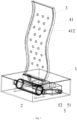
Fig. 1 is a schematic diagram of an entire structure of a display device in the present application. -
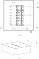
Fig. 2 is a schematic structural diagram of a side view of a display device in the present application. -
Fig. 3 is a schematic structural diagram of a front view of a display device in the present application. -
Fig. 4 is a schematic structural diagram of a top view of a display device in the present application. -
Fig. 5 is a schematic structural diagram of a display device when a flexible display screen is in an accommodated state in the present application. -
Fig. 6 is a schematic structural diagram when a flexible display screen is attached to a display screen adsorption plate in the present application. -
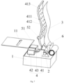
Fig. 7 is a schematic diagram of an explosive view of an entire structure of a display device in the present application. -
Fig. 8 is a schematic structural diagram of an interior of a housing in the present application. -
Fig. 9 is a schematic structural diagram of a top view of a flexible display screen and a supporting structure in the present application. -
Fig. 10 is a schematic structural diagram of a side view of a flexible display screen and a supporting structure in the present application. - 1-housing; 11-opening; 2-reel; 3-flexible display screen; 31-start end; 32-terminal end; 33-display surface; 34-fitting surface; 4-adsorption device; 41-display screen adsorption plate; 411-airflow cavity; 412-air hole; 413-adsorption surface; 42-power device; 43-power connecting pipe; 5-driving device; 51-motor; 52-conveyor belt; 6-supporting structure.
- Technical solutions of embodiments of the present application will be clearly and completely described below in conjunction with the accompanying drawings of the embodiments of the present application. Apparently, the embodiments described are merely some rather than all the embodiments of the present application. Based on the embodiments of the present application, all other embodiments obtained by those of ordinary skill in the art without making creative efforts fall within the scope of protection of the present application.
- With reference to
Figs. 1-5 and9-10 , the present application provides a display device, which includes: ahousing 1, areel 2, aflexible display screen 3, and anadsorption device 4. An accommodating space is provided inside thehousing 1, and anopening 11 is provided on a surface of thehousing 1. Thereel 2 is located in the accommodating space and is capable of rotating around its own axis. Theflexible display screen 3 has astart end 31 and aterminal end 32 opposite each other, and adisplay surface 33 and afitting surface 34 opposite each other. Thestart end 31 of theflexible display screen 3 is connected with thereel 2, and theterminal end 32 is in a free state, so that theflexible display screen 3 is capable of being rolled around thereel 2 or unrolled. When theflexible display screen 3 is in a rolled state, theflexible display screen 3 is accommodated in the accommodating space, and when theflexible display screen 3 is in an unrolled state, theterminal end 32 is capable of extending out of thehousing 1 from theopening 11. Theadsorption device 4 includes a displayscreen adsorption plate 41 located outside thehousing 1. When theflexible display screen 3 is in an unrolled state, theadsorption device 4 adsorbs theflexible display screen 3 so as to enable thefitting surface 34 to be attached to the displayscreen adsorption plate 41. - The display device includes the
housing 1, theopening 11 is provided on the surface of thehousing 1, thereel 2 is placed in thehousing 1, and theflexible display screen 3 is connected with thereel 2 and is capable of being rolled around thereel 2 or unrolled. When theflexible display screen 3 is in a rolled state, the display screen is accommodated in thehousing 1, and when theflexible display screen 3 is in an unrolled state, theterminal end 32 of theflexible display screen 3 is capable of extending out of thehousing 1 from theopening 11. The displayscreen adsorption plate 41 is provided outside thehousing 1. When theflexible display screen 3 is in an unrolled state, theadsorption device 4 may adsorb theflexible display screen 3 so as to enable the flexible display screen to be attached to the displayscreen adsorption plate 41, so that theflexible display screen 3 is capable of presenting the same shape as the displayscreen adsorption plate 41. In this case, thedisplay surface 33 is configured to display a picture normally. According to the display device, theflexible display screen 3 is enabled to be attached to the displayscreen adsorption plate 41 when being unrolled, so that theflexible display screen 3 may present different curved shapes when being unrolled, so as to fully embody a flexible aesthetic feeling. - In this way, the display device provided by the present application may achieve an effect that the
flexible display screen 3 presents different curved shapes when being unrolled. In addition, theflexible display screen 3 is accommodated in thehousing 1 when being in a rolled state, such that theflexible display screen 3 may be protected and portable. - It should be noted that the
display surface 33 is capable of displaying a picture during rolling or unrolling movement of theflexible display screen 3. - In an embodiment, with reference to
Figs. 1 ,7 and8 , the display device further includes adriving device 5 installed in the accommodating space. The driving device is configured to drive thereel 2 to rotate around its own axis so as to drive theflexible display screen 3 to be rolled or unrolled, so that theflexible display screen 3 may be accommodated and unrolled. Theflexible display screen 3 is wound around a surface of thereel 2 when being in a rolled state. As an implementation mode, the drivingdevice 5 may include amotor 51 and aconveyor belt 52, themotor 51 is provided with a driving shaft, thereel 2 is provided with a rotating shaft, and theconveyor belt 52 is connected with the driving shaft and the rotating shaft separately, so that when themotor 51 works, the driving shaft transmits power to theconveyor belt 52, and theconveyor belt 52 may drive the rotating shaft to rotate. In this way, thereel 2 is capable of rotating around its own axis. Meanwhile, theflexible display screen 3 may be automatically rolled and unrolled, such that theflexible display screen 3 has a smaller size after being rolled, and portability is improved. - It should be noted that when the
driving device 5 drives thereel 2 to rotate so as to enable theflexible display screen 3 to be rolled or unrolled, the drivingdevice 5 may be further configured to control a rolling length or an unrolling length of theflexible display screen 3. As an implementation mode, for controlling the rolling length or the unrolling length of theflexible display screen 3, the rolling length or the unrolling length of theflexible display screen 3 may be controlled by the drivingdevice 5 through a single chip microcomputer or programmable logic controller (PLC), a PLC program is set on thedriving device 5 according to a size of theflexible display screen 3, and thedriving device 5 is controlled to be turned on or off by automatically controlling and measuring the rolling length or the unrolling length of theflexible display screen 3, so that theflexible display screen 3 may be prevented from being damaged by excessive rolling or unrolling. Use requirements of the display device by different users in different scenes may be fully satisfied by controlling the rolling length or unrolling length of theflexible display screen 3, so that the display device is more convenient to use and more adaptable. - In an embodiment, with reference to
Figs. 7 ,9 and10 , in the display device, a supportingstructure 6 is connected between the start end 31 of theflexible display screen 3 and thereel 2, and the supportingstructure 6 is in smooth and transitional connection with thestart end 31 and is fixedly connected with thereel 2. By providing the supportingstructure 6, theflexible display screen 3 may be prevented from being damaged by stress concentrated at the edge of the flexible display screen in a rolling process, so that theflexible display screen 3 may be smoother in the rolled state and unrolled state. - Specifically, the supporting
structure 6 may be preferably made of rubber or other elastic materials, and a thickness of the supporting structure may be 60 µm-150 µm, so that theflexible display screen 3 is better prevented from being damaged by the stress concentrated at the edge of the flexible display screen in a rolling process. - In an embodiment, with reference to
Figs. 6 and7 , theadsorption device 4 in the present application further includes apower device 42 and apower connecting pipe 43 that are located in the accommodating space. Meanwhile, a hollow structure is provided inside the displayscreen adsorption plate 41 to form anairflow cavity 411 in communication with thepower connecting pipe 43, and theadsorption surface 413, configured to be attached to theflexible display screen 3, of the displayscreen adsorption plate 41 is provided with a plurality ofair holes 412 in communication with theairflow cavity 411. Thepower device 42 is configured to be connected with thepower connecting pipe 43, and form adsorption air pressure at the air holes 412 on theadsorption surface 413 through airflow changes in theairflow cavity 411 when thepower connecting pipe 43 is in communication with theairflow cavity 411. In this way, theflexible display screen 3 is completely attached to the display screen adsorption plate. With the above structure, thepower device 42 may control airflow in theairflow cavity 411 according to a size of the display screen, so as to control the adsorption air pressure of different sizes, so that display screens with different sizes may be better attached to the displayscreen adsorption plate 41, and further a better display effect may be ensured. - It should be noted that in the embodiment, a thickness of the
airflow cavity 411 may be 10 mm-12 mm, so that sufficient airflow in theairflow cavity 411 may be ensured to form the adsorption air pressure at the air holes 412. - It should also be noted that in the embodiment, with reference to
Fig. 7 , the plurality ofair holes 412 include a plurality of rows ofair holes 412 evenly arranged in an extension direction of the displayscreen adsorption plate 41. Each row ofair holes 412 includes a plurality of air holes 412. The even adsorption air pressure of eachair hole 412 may be better ensured by evenly arranging the air holes 412, so that theflexible display screen 3 may be better attached to the displayscreen adsorption plate 41, and a display effect may be further ensured. - Specifically, as an implementation mode, a diameter of each air hole may be selected to be 6 mm-10 mm. Based on even arrangement of the plurality of rows of
air holes 412, the display screen adsorption plate has a first end closer to the housing and a second end farther from the housing, a distance between a center of an air hole in a row ofair holes 412 closest to the second end and the second end is 25 mm-35 mm, and a distance between a center of an air hole in a row ofair holes 412 closest to the first end and the first end is 15 mm-25 mm. The above arrangement of the air holes 412 may better achieve an attaching effect between theflexible display screen 3 and the displayscreen adsorption plate 41. The distance between the center of the air hole in the row ofair holes 412 closest to the second end and the second end is preferably 30 mm, and the distance between the center of the air hole in the row ofair holes 412 closest to the first end and the first end is preferably 20 mm. - It should be noted that the center of the
above air hole 412 may be understood as a central axis of theair hole 412. Moreover, because a distance between an uppermost row ofair holes 412 and the second end is small, that is, a width of an upper end of the displayscreen adsorption plate 41 without the air holes 412 is small, even if theflexible display screen 3 completely covers the displayscreen adsorption plate 41, theflexible display screen 3 may be kept completely attached to the displayscreen adsorption plate 41. - It should be noted that the above arrangement of the air holes 412 is only illustrative, and the arrangement may also be designed according to different requirements.
- It should also be noted that when the
flexible display screen 3 is in an unrolled state or in a process of retracting into thehousing 1 from an unrolled state, theopening 11 has a guide surface, and the guiding surface is smoothly connected with theadsorption surface 413 so as to prevent theflexible display screen 3 from being scratched when being unrolled or retracted. Meanwhile, thehousing 1 may be made of metal, acrylic or other materials. - In addition, the
adsorption surface 413 of the displayscreen adsorption plate 41 and the guide surface are located on the same side of theopening 11, and an included angle between theadsorption surface 413 of the displayscreen adsorption plate 41 and the surface of theopening 11 is 90°-135°, so that theflexible display screen 3 may be smoothly adsorbed to theadsorption surface 413 when extending out of theopening 11. Meanwhile, the included angle should not be too large, so as to prevent theflexible display screen 3 from being damaged by stress concentrated at theopening 11. - In order to ensure a shape effect of the
flexible display screen 3 fixed to the displayscreen adsorption plate 41, the displayscreen adsorption plate 41 may be made of a transparent acrylic plate, etc. Meanwhile, if a curved shape needs to be changed in a display process, the displayscreen adsorption plate 41 may be made of materials with low-modulus and easy to mold, so as to change a shape in a use process. Alternatively, the displayscreen adsorption plate 41 is detachably installed on a surface of a side of thehousing 1 with theopening 11. When a shape of the unrolledflexible display screen 3 needs to be changed, different shapes of the flexible display screen during display may be achieved by replacing the displayscreen adsorption plate 41. Furthermore, with reference toFig. 5 , since the displayscreen adsorption plate 41 is detachably installed outside thehousing 1, when theflexible display screen 3 is rolled and accommodated in thehousing 1, the displayscreen adsorption plate 41 may be detached, so that a size of the display device is reduced, and further portability is improved. - Furthermore, the
fitting surface 34 of theflexible display screen 3 is provided with a polyethylene terephthalate (PET) protective film. The protective film has scratch resistance and high reliability, so that flatness of theflexible display screen 3 in the rolling or unrolling process may be further ensured. - In an embodiment, in order to achieve a better display effect, the
flexible display screen 3 may be, but is not limited to, a transparent narrow-bezel display screen. The transparent narrow-bezel display screen may include: a back protective film, a first transparent optical adhesive, an organic light-emitting diode (OLED) display panel, a second transparent optical adhesive, and a front protective film, and the second transparent optical adhesive and the front protective film may be removed as appropriate. With the structure, a thickness range of theflexible display screen 3 may be 100 µm-150 µm. With the thickness, not only theflexible display screen 3 may be better rolled on thereel 2, but also a stress difference between a structural layer closest to the reel and a structural layer farthest from the reel of theflexible display screen 3 is smaller, which is more conducive to rolling of theflexible display screen 3 and enables the flexible display screen to be better attached to the displayscreen adsorption plate 41. - Apparently, those skilled in the art can make various modifications and variations to the examples of the present application without departing from the spirit and scope of the present application. In this way, if the modifications and variations of the present application fall within the scope of the claims of the present application and their equivalent technologies, the present application is also intended to cover the modifications and variations.
Claims (17)
- A display device, comprising:a housing, wherein an accommodating space is provided inside the housing, and an opening is provided on a surface of the housing;a reel, rotatably installed in the accommodating space around its own axis;a flexible display screen, having a start end and a terminal end opposite each other, and a display surface and a fitting surface opposite each other; wherein the start end is connected with the reel, and the terminal end is in a free state to allow the flexible display screen is capable of being rolled around the reel or unrolled; and when the flexible display screen is in a rolled state, the flexible display screen is accommodated in the accommodating space, and when the flexible display screen is in an unrolled state, the terminal end extends out of the housing from the opening; andan adsorption device, comprising a display screen adsorption plate located outside the housing, and the display screen adsorption plate is provided with an adsorption surface, wherein when the flexible display screen is in an unrolled state, the adsorption device adsorbs the flexible display screen to enable the fitting surface to be attached to the adsorption surface.
- The display device according to claim 1, further comprising a driving device installed in the accommodating space; wherein the driving device is configured to drive the reel to rotate around its own axis to drive the flexible display screen to be rolled or unrolled, and when the flexible display screen is in a rolled state, the flexible display screen is wound around a surface of the reel.
- The display device according to claim 2, wherein the driving device comprises a driving motor and a conveyor belt, the reel is provided with a rotating shaft, the driving motor is provided with a driving shaft, the conveyor belt is connected with the rotating shaft and the driving shaft separately, and the driving shaft drives the rotating shaft to rotate around its own axis by the conveyor belt.
- The display device according to claim 1, wherein a supporting structure is connected between the start end of the flexible display screen and the reel, and the supporting structure is in smooth and transitional connection with the start end.
- The display device according to claim 4, wherein a thickness of the supporting structure is 60 µm-150 µm.
- The display device according to claim 4, wherein the supporting structure is made of rubber.
- The display device according to claim 1, wherein the adsorption device further comprises a power device and a power connecting pipe located in the accommodating space;a hollow structure is provided inside the display screen adsorption plate to form an airflow cavity in communication with the power connecting pipe, and the adsorption surface of the display screen adsorption plate is provided with a plurality of air holes in communication with the airflow cavity; andthe power device is configured to be connected with the power connecting pipe to form adsorption air pressure for adsorbing the flexible display screen at the plurality of air holes.
- The display device according to claim 7, wherein a thickness of the airflow cavity is 10 µm-12 µm.
- The display device according to claim 7, wherein the air holes comprise a plurality of rows of air holes evenly arranged in an extension direction of the display screen adsorption plate, and each row of air holes comprise a plurality of air holes.
- The display device according to claim 9, wherein a diameter of each of the plurality of air holes is 6 µm-10 µm.
- The display device according to claim 10, wherein the display screen adsorption plate has a first end closer to the housing and a second end farther from the housing, a distance between a center of an air hole in a row of air holes closest to the second end and the second end is 25 mm-35 mm, and a distance between a center of an air hole in a row of air holes closest to the first end and the first end is 15 mm-25 mm.
- The display device according to claim 7, wherein the opening is provided with a guide surface, and the guide surface is in smooth and transitional connection with the adsorption surface.
- The display device according to claim 12, wherein an included angle between the adsorption surface and a surface of a side of the housing with the opening is 90°-135°.
- The display device according to claim 7, wherein the display screen adsorption plate is made of a transparent acrylic plate.
- The display device according to claim 7, wherein the fitting surface is provided with a polyethylene terephthalate (PET) protective film.
- The display device according to claim 1, wherein the display screen adsorption plate is detachably installed on a surface of a side of the housing with the opening.
- The display device according to any one of claims 1-16, wherein a thickness of the flexible display screen is 100 µm-150 µm.
Applications Claiming Priority (1)
| Application Number | Priority Date | Filing Date | Title |
|---|---|---|---|
| PCT/CN2020/132894 WO2022110193A1 (en) | 2020-11-30 | 2020-11-30 | Display device |
Publications (4)
| Publication Number | Publication Date |
|---|---|
| EP4220610A1 true EP4220610A1 (en) | 2023-08-02 |
| EP4220610A4 EP4220610A4 (en) | 2023-11-22 |
| EP4220610C0 EP4220610C0 (en) | 2025-12-31 |
| EP4220610B1 EP4220610B1 (en) | 2025-12-31 |
Family
ID=81753912
Family Applications (1)
| Application Number | Title | Priority Date | Filing Date |
|---|---|---|---|
| EP20963081.3A Active EP4220610B1 (en) | 2020-11-30 | 2020-11-30 | DISPLAY DEVICE |
Country Status (4)
| Country | Link |
|---|---|
| US (1) | US12464659B2 (en) |
| EP (1) | EP4220610B1 (en) |
| CN (1) | CN114846531A (en) |
| WO (1) | WO2022110193A1 (en) |
Families Citing this family (2)
| Publication number | Priority date | Publication date | Assignee | Title |
|---|---|---|---|---|
| DE102019131505B4 (en) * | 2019-11-21 | 2021-08-12 | Audi Ag | Arrangement for a component |
| CN115240553B (en) * | 2022-07-28 | 2023-11-21 | 昆山国显光电有限公司 | Electronic equipment |
Family Cites Families (23)
| Publication number | Priority date | Publication date | Assignee | Title |
|---|---|---|---|---|
| US20080247126A1 (en) * | 2007-04-04 | 2008-10-09 | Motorola, Inc. | Retractable display assembly and electronic device |
| WO2014200466A1 (en) * | 2013-06-11 | 2014-12-18 | Empire Technology Development Llc | Display devices and methods of using the same |
| EP3761293B1 (en) * | 2015-07-07 | 2023-01-04 | LG Electronics Inc. | Display device |
| KR102454386B1 (en) | 2016-04-29 | 2022-10-17 | 엘지디스플레이 주식회사 | Rollable flexible display device |
| CN205943347U (en) | 2016-07-08 | 2017-02-08 | 广东欧珀移动通信有限公司 | Flexible display device and mobile terminal |
| CN106128312A (en) * | 2016-08-30 | 2016-11-16 | 京东方科技集团股份有限公司 | Flexible display screen and include the display device of this flexible display screen |
| US10602623B1 (en) * | 2017-01-04 | 2020-03-24 | Apple Inc. | Electronic device with flexible display structures |
| TWI623831B (en) * | 2017-02-08 | 2018-05-11 | 研能科技股份有限公司 | Flexible display device |
| CN107067981A (en) * | 2017-04-17 | 2017-08-18 | 京东方科技集团股份有限公司 | Flexible display apparatus and mobile terminal |
| CN107229372B (en) | 2017-06-29 | 2020-06-23 | 联想(北京)有限公司 | Display terminal and electronic equipment |
| KR102396025B1 (en) * | 2017-11-07 | 2022-05-09 | 엘지디스플레이 주식회사 | Rollable display apparatus |
| CN108597373B (en) | 2018-04-20 | 2020-03-17 | 云谷(固安)科技有限公司 | Attaching device and attaching method for special-shaped curved surface cover plate and flexible screen |
| AU2019310549B2 (en) * | 2018-07-23 | 2021-12-09 | Guangdong Oppo Mobile Telecommunications Corp., Ltd. | Portable electronic apparatus and flexible display device thereof |
| CN108664087A (en) | 2018-07-23 | 2018-10-16 | Oppo广东移动通信有限公司 | Portable electronic device and its flexible display apparatus |
| CN209118664U (en) | 2018-12-03 | 2019-07-16 | Oppo(重庆)智能科技有限公司 | Flexible screen components and electronic equipment |
| KR102737077B1 (en) * | 2018-12-10 | 2024-12-03 | 엘지디스플레이 주식회사 | Back plate and Rollable Display having the same |
| CN111326069A (en) | 2018-12-17 | 2020-06-23 | 上海和辉光电有限公司 | Flexible display device and mobile terminal |
| CN210223370U (en) | 2019-06-21 | 2020-03-31 | 深圳市柔宇科技有限公司 | Lifting mechanism, flexible screen display device and electronic device |
| WO2021034000A1 (en) * | 2019-08-16 | 2021-02-25 | 엘지전자 주식회사 | Display device |
| CN111365336B (en) * | 2020-04-17 | 2022-04-01 | Oppo广东移动通信有限公司 | Attaching jig and attaching method for display screen assembly |
| CN111583804B (en) | 2020-05-26 | 2022-03-08 | 合肥维信诺科技有限公司 | Flexible display device and display equipment |
| CN112863363B (en) * | 2021-03-04 | 2022-08-05 | 武汉华星光电半导体显示技术有限公司 | Curling display device |
| KR102891636B1 (en) * | 2021-12-30 | 2025-11-27 | 엘지디스플레이 주식회사 | Display device |
-
2020
- 2020-11-30 WO PCT/CN2020/132894 patent/WO2022110193A1/en not_active Ceased
- 2020-11-30 CN CN202080003114.5A patent/CN114846531A/en active Pending
- 2020-11-30 EP EP20963081.3A patent/EP4220610B1/en active Active
- 2020-11-30 US US18/032,596 patent/US12464659B2/en active Active
Also Published As
| Publication number | Publication date |
|---|---|
| CN114846531A (en) | 2022-08-02 |
| US12464659B2 (en) | 2025-11-04 |
| US20230389200A1 (en) | 2023-11-30 |
| WO2022110193A1 (en) | 2022-06-02 |
| EP4220610C0 (en) | 2025-12-31 |
| EP4220610B1 (en) | 2025-12-31 |
| EP4220610A4 (en) | 2023-11-22 |
Similar Documents
| Publication | Publication Date | Title |
|---|---|---|
| US11809231B2 (en) | Display device with flexible display panel connected to transmission mechanism | |
| CN113411421B (en) | Electronic equipment | |
| KR102233448B1 (en) | Electronic device with wrapped display | |
| WO2016065542A1 (en) | Electronic device having flexible screen | |
| KR20190051541A (en) | Rollable display apparatus | |
| EP3196730B1 (en) | Flexible screen module and electronic device having the module | |
| KR102446193B1 (en) | rollable display device | |
| US12464659B2 (en) | Display device | |
| WO2021129730A1 (en) | Shell assembly and electronic device | |
| US20200196459A1 (en) | Flexible display device and mobile terminal | |
| CN206564106U (en) | Flexible display device | |
| TW202036235A (en) | Context-aware user interface (ui) for multi-form factor information handling systems (ihss) | |
| US20040052037A1 (en) | Display support apparatus | |
| WO2021129728A1 (en) | Housing assembly and electronic device | |
| CN212278267U (en) | Display device | |
| CN107528945B (en) | Mobile terminal | |
| KR102413109B1 (en) | Flexible Display Device | |
| CN203851182U (en) | a mobile terminal | |
| CN102902308A (en) | Expandable mobile device | |
| WO2016089903A1 (en) | Slidable display apparatus | |
| KR20230102625A (en) | Display device | |
| CN114006961A (en) | Folding device and electronic equipment | |
| CN103956079A (en) | Roller shutter cabinet type multimedia teaching integrated machine capable of mobile use | |
| CN202035031U (en) | Flexible display film mobile phone | |
| CN209461081U (en) | Flexible display apparatus |
Legal Events
| Date | Code | Title | Description |
|---|---|---|---|
| STAA | Information on the status of an ep patent application or granted ep patent |
Free format text: STATUS: THE INTERNATIONAL PUBLICATION HAS BEEN MADE |
|
| PUAI | Public reference made under article 153(3) epc to a published international application that has entered the european phase |
Free format text: ORIGINAL CODE: 0009012 |
|
| STAA | Information on the status of an ep patent application or granted ep patent |
Free format text: STATUS: REQUEST FOR EXAMINATION WAS MADE |
|
| 17P | Request for examination filed |
Effective date: 20230424 |
|
| AK | Designated contracting states |
Kind code of ref document: A1 Designated state(s): AL AT BE BG CH CY CZ DE DK EE ES FI FR GB GR HR HU IE IS IT LI LT LU LV MC MK MT NL NO PL PT RO RS SE SI SK SM TR |
|
| A4 | Supplementary search report drawn up and despatched |
Effective date: 20231023 |
|
| RIC1 | Information provided on ipc code assigned before grant |
Ipc: G06F 1/16 20060101ALI20231017BHEP Ipc: G09F 9/30 20060101AFI20231017BHEP |
|
| DAV | Request for validation of the european patent (deleted) | ||
| DAX | Request for extension of the european patent (deleted) | ||
| GRAP | Despatch of communication of intention to grant a patent |
Free format text: ORIGINAL CODE: EPIDOSNIGR1 |
|
| RIC1 | Information provided on ipc code assigned before grant |
Ipc: G09F 9/30 20060101AFI20250718BHEP Ipc: G06F 1/16 20060101ALI20250718BHEP |
|
| STAA | Information on the status of an ep patent application or granted ep patent |
Free format text: STATUS: GRANT OF PATENT IS INTENDED |
|
| INTG | Intention to grant announced |
Effective date: 20250828 |
|
| GRAS | Grant fee paid |
Free format text: ORIGINAL CODE: EPIDOSNIGR3 |
|
| GRAA | (expected) grant |
Free format text: ORIGINAL CODE: 0009210 |
|
| STAA | Information on the status of an ep patent application or granted ep patent |
Free format text: STATUS: THE PATENT HAS BEEN GRANTED |
|
| AK | Designated contracting states |
Kind code of ref document: B1 Designated state(s): AL AT BE BG CH CY CZ DE DK EE ES FI FR GB GR HR HU IE IS IT LI LT LU LV MC MK MT NL NO PL PT RO RS SE SI SK SM TR |
|
| REG | Reference to a national code |
Ref country code: CH Ref legal event code: F10 Free format text: ST27 STATUS EVENT CODE: U-0-0-F10-F00 (AS PROVIDED BY THE NATIONAL OFFICE) Effective date: 20251231 Ref country code: GB Ref legal event code: FG4D |
|
| REG | Reference to a national code |
Ref country code: DE Ref legal event code: R096 Ref document number: 602020065008 Country of ref document: DE |
|
| REG | Reference to a national code |
Ref country code: IE Ref legal event code: FG4D |
|
| U01 | Request for unitary effect filed |
Effective date: 20260127 |
|
| U07 | Unitary effect registered |
Designated state(s): AT BE BG DE DK EE FI FR IT LT LU LV MT NL PT RO SE SI Effective date: 20260130 |
|
| PG25 | Lapsed in a contracting state [announced via postgrant information from national office to epo] |
Ref country code: NO Free format text: LAPSE BECAUSE OF FAILURE TO SUBMIT A TRANSLATION OF THE DESCRIPTION OR TO PAY THE FEE WITHIN THE PRESCRIBED TIME-LIMIT Effective date: 20260331 |
|
| PG25 | Lapsed in a contracting state [announced via postgrant information from national office to epo] |
Ref country code: HR Free format text: LAPSE BECAUSE OF FAILURE TO SUBMIT A TRANSLATION OF THE DESCRIPTION OR TO PAY THE FEE WITHIN THE PRESCRIBED TIME-LIMIT Effective date: 20251231 |
|
| PG25 | Lapsed in a contracting state [announced via postgrant information from national office to epo] |
Ref country code: RS Free format text: LAPSE BECAUSE OF FAILURE TO SUBMIT A TRANSLATION OF THE DESCRIPTION OR TO PAY THE FEE WITHIN THE PRESCRIBED TIME-LIMIT Effective date: 20260331 |
|
| PG25 | Lapsed in a contracting state [announced via postgrant information from national office to epo] |
Ref country code: SM Free format text: LAPSE BECAUSE OF FAILURE TO SUBMIT A TRANSLATION OF THE DESCRIPTION OR TO PAY THE FEE WITHIN THE PRESCRIBED TIME-LIMIT Effective date: 20251231 |
|
| PG25 | Lapsed in a contracting state [announced via postgrant information from national office to epo] |
Ref country code: ES Free format text: LAPSE BECAUSE OF FAILURE TO SUBMIT A TRANSLATION OF THE DESCRIPTION OR TO PAY THE FEE WITHIN THE PRESCRIBED TIME-LIMIT Effective date: 20251231 |
|
| PG25 | Lapsed in a contracting state [announced via postgrant information from national office to epo] |
Ref country code: PL Free format text: LAPSE BECAUSE OF FAILURE TO SUBMIT A TRANSLATION OF THE DESCRIPTION OR TO PAY THE FEE WITHIN THE PRESCRIBED TIME-LIMIT Effective date: 20251231 |
|
| PG25 | Lapsed in a contracting state [announced via postgrant information from national office to epo] |
Ref country code: IS Free format text: LAPSE BECAUSE OF FAILURE TO SUBMIT A TRANSLATION OF THE DESCRIPTION OR TO PAY THE FEE WITHIN THE PRESCRIBED TIME-LIMIT Effective date: 20260430 |
|
| PG25 | Lapsed in a contracting state [announced via postgrant information from national office to epo] |
Ref country code: CZ Free format text: LAPSE BECAUSE OF FAILURE TO SUBMIT A TRANSLATION OF THE DESCRIPTION OR TO PAY THE FEE WITHIN THE PRESCRIBED TIME-LIMIT Effective date: 20251231 |
|
| PG25 | Lapsed in a contracting state [announced via postgrant information from national office to epo] |
Ref country code: SK Free format text: LAPSE BECAUSE OF FAILURE TO SUBMIT A TRANSLATION OF THE DESCRIPTION OR TO PAY THE FEE WITHIN THE PRESCRIBED TIME-LIMIT Effective date: 20251231 |