EP4220329A1 - Method for generating a reference trajectory within a lane, method for operating a vehicle, data processing apparatus, vehicle, and computer-readable medium - Google Patents
Method for generating a reference trajectory within a lane, method for operating a vehicle, data processing apparatus, vehicle, and computer-readable medium Download PDFInfo
- Publication number
- EP4220329A1 EP4220329A1 EP22153686.5A EP22153686A EP4220329A1 EP 4220329 A1 EP4220329 A1 EP 4220329A1 EP 22153686 A EP22153686 A EP 22153686A EP 4220329 A1 EP4220329 A1 EP 4220329A1
- Authority
- EP
- European Patent Office
- Prior art keywords
- vehicle
- loss
- reference trajectory
- destination
- data processing
- Prior art date
- Legal status (The legal status is an assumption and is not a legal conclusion. Google has not performed a legal analysis and makes no representation as to the accuracy of the status listed.)
- Withdrawn
Links
Images
Classifications
-
- G—PHYSICS
- G01—MEASURING; TESTING
- G01C—MEASURING DISTANCES, LEVELS OR BEARINGS; SURVEYING; NAVIGATION; GYROSCOPIC INSTRUMENTS; PHOTOGRAMMETRY OR VIDEOGRAMMETRY
- G01C21/00—Navigation; Navigational instruments not provided for in groups G01C1/00 - G01C19/00
- G01C21/26—Navigation; Navigational instruments not provided for in groups G01C1/00 - G01C19/00 specially adapted for navigation in a road network
- G01C21/34—Route searching; Route guidance
- G01C21/3453—Special cost functions, i.e. other than distance or default speed limit of road segments
- G01C21/3469—Fuel consumption; Energy use; Emission aspects
-
- B—PERFORMING OPERATIONS; TRANSPORTING
- B60—VEHICLES IN GENERAL
- B60W—CONJOINT CONTROL OF VEHICLE SUB-UNITS OF DIFFERENT TYPE OR DIFFERENT FUNCTION; CONTROL SYSTEMS SPECIALLY ADAPTED FOR HYBRID VEHICLES; ROAD VEHICLE DRIVE CONTROL SYSTEMS FOR PURPOSES NOT RELATED TO THE CONTROL OF A PARTICULAR SUB-UNIT
- B60W30/00—Purposes of road vehicle drive control systems not related to the control of a particular sub-unit, e.g. of systems using conjoint control of vehicle sub-units
- B60W30/10—Path keeping
- B60W30/12—Lane keeping
-
- B—PERFORMING OPERATIONS; TRANSPORTING
- B60—VEHICLES IN GENERAL
- B60W—CONJOINT CONTROL OF VEHICLE SUB-UNITS OF DIFFERENT TYPE OR DIFFERENT FUNCTION; CONTROL SYSTEMS SPECIALLY ADAPTED FOR HYBRID VEHICLES; ROAD VEHICLE DRIVE CONTROL SYSTEMS FOR PURPOSES NOT RELATED TO THE CONTROL OF A PARTICULAR SUB-UNIT
- B60W30/00—Purposes of road vehicle drive control systems not related to the control of a particular sub-unit, e.g. of systems using conjoint control of vehicle sub-units
- B60W30/10—Path keeping
-
- B—PERFORMING OPERATIONS; TRANSPORTING
- B60—VEHICLES IN GENERAL
- B60W—CONJOINT CONTROL OF VEHICLE SUB-UNITS OF DIFFERENT TYPE OR DIFFERENT FUNCTION; CONTROL SYSTEMS SPECIALLY ADAPTED FOR HYBRID VEHICLES; ROAD VEHICLE DRIVE CONTROL SYSTEMS FOR PURPOSES NOT RELATED TO THE CONTROL OF A PARTICULAR SUB-UNIT
- B60W10/00—Conjoint control of vehicle sub-units of different type or different function
- B60W10/20—Conjoint control of vehicle sub-units of different type or different function including control of steering systems
-
- B—PERFORMING OPERATIONS; TRANSPORTING
- B60—VEHICLES IN GENERAL
- B60W—CONJOINT CONTROL OF VEHICLE SUB-UNITS OF DIFFERENT TYPE OR DIFFERENT FUNCTION; CONTROL SYSTEMS SPECIALLY ADAPTED FOR HYBRID VEHICLES; ROAD VEHICLE DRIVE CONTROL SYSTEMS FOR PURPOSES NOT RELATED TO THE CONTROL OF A PARTICULAR SUB-UNIT
- B60W30/00—Purposes of road vehicle drive control systems not related to the control of a particular sub-unit, e.g. of systems using conjoint control of vehicle sub-units
- B60W30/18—Propelling the vehicle
- B60W30/18009—Propelling the vehicle related to particular drive situations
- B60W30/18145—Cornering
-
- B—PERFORMING OPERATIONS; TRANSPORTING
- B60—VEHICLES IN GENERAL
- B60W—CONJOINT CONTROL OF VEHICLE SUB-UNITS OF DIFFERENT TYPE OR DIFFERENT FUNCTION; CONTROL SYSTEMS SPECIALLY ADAPTED FOR HYBRID VEHICLES; ROAD VEHICLE DRIVE CONTROL SYSTEMS FOR PURPOSES NOT RELATED TO THE CONTROL OF A PARTICULAR SUB-UNIT
- B60W40/00—Estimation or calculation of non-directly measurable driving parameters for road vehicle drive control systems not related to the control of a particular sub unit, e.g. by using mathematical models
- B60W40/02—Estimation or calculation of non-directly measurable driving parameters for road vehicle drive control systems not related to the control of a particular sub unit, e.g. by using mathematical models related to ambient conditions
- B60W40/06—Road conditions
-
- B—PERFORMING OPERATIONS; TRANSPORTING
- B60—VEHICLES IN GENERAL
- B60W—CONJOINT CONTROL OF VEHICLE SUB-UNITS OF DIFFERENT TYPE OR DIFFERENT FUNCTION; CONTROL SYSTEMS SPECIALLY ADAPTED FOR HYBRID VEHICLES; ROAD VEHICLE DRIVE CONTROL SYSTEMS FOR PURPOSES NOT RELATED TO THE CONTROL OF A PARTICULAR SUB-UNIT
- B60W40/00—Estimation or calculation of non-directly measurable driving parameters for road vehicle drive control systems not related to the control of a particular sub unit, e.g. by using mathematical models
- B60W40/10—Estimation or calculation of non-directly measurable driving parameters for road vehicle drive control systems not related to the control of a particular sub unit, e.g. by using mathematical models related to vehicle motion
- B60W40/103—Side slip angle of vehicle body
-
- B—PERFORMING OPERATIONS; TRANSPORTING
- B60—VEHICLES IN GENERAL
- B60W—CONJOINT CONTROL OF VEHICLE SUB-UNITS OF DIFFERENT TYPE OR DIFFERENT FUNCTION; CONTROL SYSTEMS SPECIALLY ADAPTED FOR HYBRID VEHICLES; ROAD VEHICLE DRIVE CONTROL SYSTEMS FOR PURPOSES NOT RELATED TO THE CONTROL OF A PARTICULAR SUB-UNIT
- B60W40/00—Estimation or calculation of non-directly measurable driving parameters for road vehicle drive control systems not related to the control of a particular sub unit, e.g. by using mathematical models
- B60W40/10—Estimation or calculation of non-directly measurable driving parameters for road vehicle drive control systems not related to the control of a particular sub unit, e.g. by using mathematical models related to vehicle motion
- B60W40/105—Speed
-
- B—PERFORMING OPERATIONS; TRANSPORTING
- B60—VEHICLES IN GENERAL
- B60W—CONJOINT CONTROL OF VEHICLE SUB-UNITS OF DIFFERENT TYPE OR DIFFERENT FUNCTION; CONTROL SYSTEMS SPECIALLY ADAPTED FOR HYBRID VEHICLES; ROAD VEHICLE DRIVE CONTROL SYSTEMS FOR PURPOSES NOT RELATED TO THE CONTROL OF A PARTICULAR SUB-UNIT
- B60W40/00—Estimation or calculation of non-directly measurable driving parameters for road vehicle drive control systems not related to the control of a particular sub unit, e.g. by using mathematical models
- B60W40/10—Estimation or calculation of non-directly measurable driving parameters for road vehicle drive control systems not related to the control of a particular sub unit, e.g. by using mathematical models related to vehicle motion
- B60W40/114—Yaw movement
-
- B—PERFORMING OPERATIONS; TRANSPORTING
- B60—VEHICLES IN GENERAL
- B60W—CONJOINT CONTROL OF VEHICLE SUB-UNITS OF DIFFERENT TYPE OR DIFFERENT FUNCTION; CONTROL SYSTEMS SPECIALLY ADAPTED FOR HYBRID VEHICLES; ROAD VEHICLE DRIVE CONTROL SYSTEMS FOR PURPOSES NOT RELATED TO THE CONTROL OF A PARTICULAR SUB-UNIT
- B60W60/00—Drive control systems specially adapted for autonomous road vehicles
- B60W60/001—Planning or execution of driving tasks
- B60W60/0023—Planning or execution of driving tasks in response to energy consumption
-
- G—PHYSICS
- G01—MEASURING; TESTING
- G01C—MEASURING DISTANCES, LEVELS OR BEARINGS; SURVEYING; NAVIGATION; GYROSCOPIC INSTRUMENTS; PHOTOGRAMMETRY OR VIDEOGRAMMETRY
- G01C21/00—Navigation; Navigational instruments not provided for in groups G01C1/00 - G01C19/00
- G01C21/26—Navigation; Navigational instruments not provided for in groups G01C1/00 - G01C19/00 specially adapted for navigation in a road network
- G01C21/34—Route searching; Route guidance
- G01C21/36—Input/output arrangements for on-board computers
- G01C21/3626—Details of the output of route guidance instructions
- G01C21/3658—Lane guidance
-
- B—PERFORMING OPERATIONS; TRANSPORTING
- B60—VEHICLES IN GENERAL
- B60W—CONJOINT CONTROL OF VEHICLE SUB-UNITS OF DIFFERENT TYPE OR DIFFERENT FUNCTION; CONTROL SYSTEMS SPECIALLY ADAPTED FOR HYBRID VEHICLES; ROAD VEHICLE DRIVE CONTROL SYSTEMS FOR PURPOSES NOT RELATED TO THE CONTROL OF A PARTICULAR SUB-UNIT
- B60W50/00—Details of control systems for road vehicle drive control not related to the control of a particular sub-unit, e.g. process diagnostic or vehicle driver interfaces
- B60W2050/0001—Details of the control system
- B60W2050/0002—Automatic control, details of type of controller or control system architecture
- B60W2050/0013—Optimal controllers
-
- B—PERFORMING OPERATIONS; TRANSPORTING
- B60—VEHICLES IN GENERAL
- B60W—CONJOINT CONTROL OF VEHICLE SUB-UNITS OF DIFFERENT TYPE OR DIFFERENT FUNCTION; CONTROL SYSTEMS SPECIALLY ADAPTED FOR HYBRID VEHICLES; ROAD VEHICLE DRIVE CONTROL SYSTEMS FOR PURPOSES NOT RELATED TO THE CONTROL OF A PARTICULAR SUB-UNIT
- B60W50/00—Details of control systems for road vehicle drive control not related to the control of a particular sub-unit, e.g. process diagnostic or vehicle driver interfaces
- B60W2050/0001—Details of the control system
- B60W2050/0019—Control system elements or transfer functions
- B60W2050/0028—Mathematical models, e.g. for simulation
- B60W2050/0031—Mathematical model of the vehicle
-
- B—PERFORMING OPERATIONS; TRANSPORTING
- B60—VEHICLES IN GENERAL
- B60W—CONJOINT CONTROL OF VEHICLE SUB-UNITS OF DIFFERENT TYPE OR DIFFERENT FUNCTION; CONTROL SYSTEMS SPECIALLY ADAPTED FOR HYBRID VEHICLES; ROAD VEHICLE DRIVE CONTROL SYSTEMS FOR PURPOSES NOT RELATED TO THE CONTROL OF A PARTICULAR SUB-UNIT
- B60W50/00—Details of control systems for road vehicle drive control not related to the control of a particular sub-unit, e.g. process diagnostic or vehicle driver interfaces
- B60W2050/0001—Details of the control system
- B60W2050/0019—Control system elements or transfer functions
- B60W2050/0028—Mathematical models, e.g. for simulation
- B60W2050/0037—Mathematical models of vehicle sub-units
- B60W2050/0039—Mathematical models of vehicle sub-units of the propulsion unit
-
- B—PERFORMING OPERATIONS; TRANSPORTING
- B60—VEHICLES IN GENERAL
- B60W—CONJOINT CONTROL OF VEHICLE SUB-UNITS OF DIFFERENT TYPE OR DIFFERENT FUNCTION; CONTROL SYSTEMS SPECIALLY ADAPTED FOR HYBRID VEHICLES; ROAD VEHICLE DRIVE CONTROL SYSTEMS FOR PURPOSES NOT RELATED TO THE CONTROL OF A PARTICULAR SUB-UNIT
- B60W50/00—Details of control systems for road vehicle drive control not related to the control of a particular sub-unit, e.g. process diagnostic or vehicle driver interfaces
- B60W2050/0001—Details of the control system
- B60W2050/0019—Control system elements or transfer functions
- B60W2050/0028—Mathematical models, e.g. for simulation
- B60W2050/0037—Mathematical models of vehicle sub-units
- B60W2050/0041—Mathematical models of vehicle sub-units of the drive line
-
- B—PERFORMING OPERATIONS; TRANSPORTING
- B60—VEHICLES IN GENERAL
- B60W—CONJOINT CONTROL OF VEHICLE SUB-UNITS OF DIFFERENT TYPE OR DIFFERENT FUNCTION; CONTROL SYSTEMS SPECIALLY ADAPTED FOR HYBRID VEHICLES; ROAD VEHICLE DRIVE CONTROL SYSTEMS FOR PURPOSES NOT RELATED TO THE CONTROL OF A PARTICULAR SUB-UNIT
- B60W2520/00—Input parameters relating to overall vehicle dynamics
- B60W2520/10—Longitudinal speed
-
- B—PERFORMING OPERATIONS; TRANSPORTING
- B60—VEHICLES IN GENERAL
- B60W—CONJOINT CONTROL OF VEHICLE SUB-UNITS OF DIFFERENT TYPE OR DIFFERENT FUNCTION; CONTROL SYSTEMS SPECIALLY ADAPTED FOR HYBRID VEHICLES; ROAD VEHICLE DRIVE CONTROL SYSTEMS FOR PURPOSES NOT RELATED TO THE CONTROL OF A PARTICULAR SUB-UNIT
- B60W2520/00—Input parameters relating to overall vehicle dynamics
- B60W2520/14—Yaw
-
- B—PERFORMING OPERATIONS; TRANSPORTING
- B60—VEHICLES IN GENERAL
- B60W—CONJOINT CONTROL OF VEHICLE SUB-UNITS OF DIFFERENT TYPE OR DIFFERENT FUNCTION; CONTROL SYSTEMS SPECIALLY ADAPTED FOR HYBRID VEHICLES; ROAD VEHICLE DRIVE CONTROL SYSTEMS FOR PURPOSES NOT RELATED TO THE CONTROL OF A PARTICULAR SUB-UNIT
- B60W2520/00—Input parameters relating to overall vehicle dynamics
- B60W2520/20—Sideslip angle
-
- B—PERFORMING OPERATIONS; TRANSPORTING
- B60—VEHICLES IN GENERAL
- B60W—CONJOINT CONTROL OF VEHICLE SUB-UNITS OF DIFFERENT TYPE OR DIFFERENT FUNCTION; CONTROL SYSTEMS SPECIALLY ADAPTED FOR HYBRID VEHICLES; ROAD VEHICLE DRIVE CONTROL SYSTEMS FOR PURPOSES NOT RELATED TO THE CONTROL OF A PARTICULAR SUB-UNIT
- B60W2552/00—Input parameters relating to infrastructure
- B60W2552/30—Road curve radius
-
- B—PERFORMING OPERATIONS; TRANSPORTING
- B60—VEHICLES IN GENERAL
- B60W—CONJOINT CONTROL OF VEHICLE SUB-UNITS OF DIFFERENT TYPE OR DIFFERENT FUNCTION; CONTROL SYSTEMS SPECIALLY ADAPTED FOR HYBRID VEHICLES; ROAD VEHICLE DRIVE CONTROL SYSTEMS FOR PURPOSES NOT RELATED TO THE CONTROL OF A PARTICULAR SUB-UNIT
- B60W2556/00—Input parameters relating to data
- B60W2556/45—External transmission of data to or from the vehicle
- B60W2556/50—External transmission of data to or from the vehicle of positioning data, e.g. GPS [Global Positioning System] data
-
- B—PERFORMING OPERATIONS; TRANSPORTING
- B60—VEHICLES IN GENERAL
- B60W—CONJOINT CONTROL OF VEHICLE SUB-UNITS OF DIFFERENT TYPE OR DIFFERENT FUNCTION; CONTROL SYSTEMS SPECIALLY ADAPTED FOR HYBRID VEHICLES; ROAD VEHICLE DRIVE CONTROL SYSTEMS FOR PURPOSES NOT RELATED TO THE CONTROL OF A PARTICULAR SUB-UNIT
- B60W2710/00—Output or target parameters relating to a particular sub-units
- B60W2710/20—Steering systems
- B60W2710/207—Steering angle of wheels
Definitions
- the present disclosure relates to a method for generating a reference trajectory within a lane for a vehicle.
- the disclosure is directed to a method for operating a vehicle.
- the present disclosure is directed to a data processing apparatus comprising means for carrying out the above methods, a vehicle comprising such a data processing apparatus, and a computer-readable medium.
- the generation of the reference trajectory may also be designated as path planning or trajectory planning.
- the path or trajectory defines where on a road or within a lane the vehicle is to be driven.
- a lane sometimes is also called a traffic lane or a track.
- a route for the vehicle defines which road or lane is to be taken.
- a trajectory generally describes a series of positions for the vehicle, in more detail a series of longitudinal and lateral positions.
- the positions may by interpolated such that the trajectory is a curve.
- Trajectories need to be generated for both autonomous vehicles and vehicles being driven by a human driver having advanced driver assistance systems, especially lane assistance.
- the latter may also be designated partially autonomous vehicles.
- the reference trajectory is generated such that it generally is located in the center of the lane. In doing so, the margins between the sides of the vehicle and the border of the lane are of substantially equal size on both sides. This ensures safe travelling of the vehicle and high comfort for the driver and the passengers.
- a method for generating a reference trajectory within a lane for a vehicle comprising:
- the current state parameter and/or the destination parameter and/or the route parameter may be received from a navigation unit.
- the navigation unit may be configured for calculating a route leading the vehicle from a current position to a destination.
- a power loss represents power that was intended to fulfill a vehicle motion request but has not been used thereto and is thus lost.
- the general idea underlying the present disclosure is to consider the energy efficiency when generating a reference trajectory.
- the vehicle current state parameter and the vehicle state parameter each comprise at least one of a corresponding longitudinal position of the vehicle, a corresponding lateral positon of the vehicle, a corresponding yaw angle of the vehicle, a corresponding longitudinal speed of the vehicle, a corresponding side-slip angle of the vehicle and a corresponding yaw rate of the vehicle.
- the vehicle current state parameter and the vehicle state parameter may relate to the same properties, however the corresponding values may be different.
- the longitudinal position of the vehicle is designated as a position along a X axis and the lateral positon is designated as a position along a Y axis.
- a yaw angle is measured around a Z axis.
- the X, Y and Z axes are perpendicular to one another.
- the side slip angle is the angle between the vehicle longitudinal direction and the traveling direction of the vehicle's center of gravity. Consequently, the vehicle current state can be described with high precision. This also applies to a vehicle state in general and the vehicle state as it evolves along the route.
- the reference trajectory is described by at least one of a reference longitudinal position, a reference lateral position, a reference yaw angle, a reference longitudinal speed and time.
- time may be travelling time.
- the reference trajectory is described in a simple and computationally efficient manner. It is understood that the reference longitudinal position, the reference lateral position, the reference yaw angle, and the reference longitudinal speed are provided as functions over time.
- the power loss comprises at least one of a propulsion loss, a transmission loss, a tire loss and a drag loss.
- the propulsion loss may comprise losses occurring in the electric motor used for propelling the vehicle and the corresponding inverter unit.
- the transmission loss comprises losses occurring in a transmission.
- the tire loss may comprise losses occurring at the interface of the tires and the road.
- the propulsion loss may be determined on a test bench where the at least one electric motor and the at least one inverter unit are operated in one or more operational points.
- the operational points are for example characterized by a torque which is provided by the electric motor. If the at least one electric motor and the at least one inverter unit are operated in more than one operational points, a curve describing the propulsion loss as a function of the provided torque can be generated using a curve fit technique. In an example, the curve fit uses a quadratic function.
- the transmission loss may be determined on a test bench where the transmission is operated in one or more operational points.
- the operational points are for example characterized by a torque which is provided at an output of the transmission. If the transmission is operated in more than one operational points, a curve describing the transmission loss as a function of the provided torque can be generated using a curve fit technique. In an example, the curve fit uses a quadratic function.
- the tire loss may comprise at least one of a longitudinal slip loss, a lateral slip loss and a rolling resistance power loss.
- the longitudinal slip loss and the lateral slip loss may be calculated by multiplying a corresponding longitudinal or lateral force with the corresponding slip velocity.
- the drag loss may be calculated as a function of a drag coefficient, the density of air and the speed of the vehicle.
- estimating the power loss comprises using a predefined power loss function.
- the predefined power loss function is a so-called "cost function”. Once the types of power losses to be considered are determined, the formulae describing these losses may be combined into the predefined power loss function. This is computationally efficient. Thus, the power loss may be derived in a reliable manner.
- the method may comprise integrating the power loss over time in order to calculate an energy loss.
- an energy loss may be easily calculated.
- an energy loss of a drive cycle may be determined and minimized in accordance with the present method.
- determining the reference trajectory may comprise respecting at least one of a drivable area, a desired speed, a minimum lateral margin, a maximum allowable side slip angle, a maximum available torque, and a road friction coefficient as a boundary condition.
- boundary condition is constraint.
- the drivable area designates the area of the lane on which the vehicle may drive.
- the drivable area may be defined within the same plane as a longitudinal and lateral position of the vehicle.
- the desired speed describes the driving behavior or the human or autonomous driver.
- the lateral margins need to be respected in order to avoid collisions with vehicles or objects on neighboring lanes.
- the maximum allowable side slip angle guarantees that the vehicle stays stable and controllable.
- the maximum available torque is a characteristic of a propulsion system of the vehicle.
- the drivable area may be received from the navigation unit. Alternatively or additionally, the drivable area may be received from a camera unit being configured for detecting a drivable area of a lane ahead of the vehicle.
- the desired speed may be derived from a speed limit being for example provided by the navigation unit. Alternatively or additionally, the desired speed may be derived from historic drive data. In a very simple case the desired speed is the historic average speed.
- the minimum lateral margin may be provided as a function of speed.
- the road friction coefficient may be received from a table or map of road coefficients.
- the road friction coefficient may also be derived from a classification of the corresponding road, e.g. highway or city road.
- the classification of the relevant road may be provided by the navigation unit.
- a standard parameter may be used as the road friction coefficient.
- the parameters being used as boundary conditions can be provided in a simple and reliable manner.
- the method comprises receiving the at least one vehicle current state parameter from a sensor unit. This is a simple and reliable way to use up-to-date input parameters when performing the method.
- a method for operating a vehicle comprising:
- the vehicle may be operated to follow the reference trajectory. Consequently, the power loss occurring while traveling along the reference trajectory is minimized. In other words, the energy efficiency of the vehicle is increased. This leads to an increased driving range of the vehicle. Also corresponding emissions per distance unit of the vehicle may be reduced.
- the method for operating a vehicle is implemented as a closed loop control method.
- one or more sensors may be used to determine a potential deviation of the vehicle from the reference trajectory.
- the sensors may comprise at least one of an inertial measurement unit for determining a yaw rate, a vehicle speed sensor for determining a vehicle speed and a positioning sensor, e.g. a GPS sensor, for determining a position of the vehicle.
- the control may be performed in real time.
- control signal may comprise a steering angle control signal.
- the vehicle can be operated such that it follows the reference trajectory without or with a minimal deviation only.
- the method comprises performing a pure pursuit control technique for controlling steering angle.
- the desired steering angle can be set with high reliability.
- the method for generating a reference trajectory within a lane for a vehicle and/or the method for operating a vehicle may be at least partly computer-implemented, and may be implemented in software or in hardware, or in software and hardware.
- a data processing apparatus comprising means for carrying out the method according to the disclosure.
- the data processing means may be a suitable computing means, such as an electronic control module etc., which may also be a distributed computer system.
- the data processing means or the computer respectively, may comprise one or more of a processor, a memory, a data interface, or the like.
- a vehicle comprising a data processing apparatus according to the third aspect of the present disclosure.
- a computer-readable medium comprising instructions which, when executed by a data processing unit, cause the data processing unit to carry out the method of the present disclosure.
- the data processing unit may be a computer.
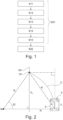
- Figure 1 shows a method for generating a reference trajectory RT within a lane for a vehicle V comprising steps S11 to S15 and a method for operating a vehicle comprising steps S21 and S22 (see also Figure 3 ).
- Step S11 of the method for generating a reference trajectory RT within a lane for a vehicle V comprises receiving at least one vehicle current state parameter describing a current state of the vehicle.
- the current state of the vehicle V is described by a position of the vehicle.
- a longitudinal position of the vehicle, a lateral positon of the vehicle, and a yaw angle of the vehicle are received.
- These vehicle current state parameters may be expressed in a vehicle coordinate system, i.e. a coordinate system having its origin on the vehicle. Alternatively, a global coordinate system may be used.
- the current state of the vehicle may be described by a longitudinal speed of the vehicle, a side-slip angle of the vehicle or a yaw rate of the vehicle. Also these vehicle current state parameters may be expressed in a vehicle coordinate system or a global coordinate system.
- the parameters describing the vehicle current state may be received from a navigation unit using GPS data. More generally, the vehicle current state parameters are received from as sensor unit.
- Step S12 comprises receiving a destination parameter.
- the destination parameter describes a destination to be reached by the vehicle.
- the destination parameter may describe a position.
- the destination parameter may be received from a navigation unit using for example GPS data.
- a further step S13 comprises receiving at least one route parameter.
- the route parameter describes a route starting at the current position of the vehicle V and ending at the destination, i.e. a route leading from the current position of the vehicle to the destination. As has been described before, a route defines which road or lane is to be taken.
- the vehicle current state and the destination parameter need to be known in order to be able to calculate the at least one route parameter.
- different routes may be available for connecting a vehicle having a current state and a destination.
- a step S14 comprises estimating a power loss P loss being caused when traveling from the current position of the vehicle V to the destination along the route.
- the power loss P loss is a function of at least one vehicle state parameter describing a state of the vehicle along the route, the destination parameter and a traveling time.
- the estimated power loss P loss comprises a propulsion loss, a transmission loss, a tire loss and a drag loss.
- the propulsion loss P P,loss describes a loss occurring in a propulsion system of the vehicle V, e.g. in an electric motor and a corresponding inverter unit.
- the parameters a 1 , a 2 , a 3 depend from a rotational speed of the propulsion motor which may be an electric motor.
- the propulsion loss P P,loss is assessed on a test bench using several operational points of the propulsion system.
- the parameters a 1 , a 2 , a 3 of the above formula are determined by performing a curve fit.
- the transmission loss P T,loss comprises a loss occurring in a transmission.
- the transmission loss P T,loss is also described by a quadratic function over torque T.
- the parameters b 1 , b 2 , b 3 depend from a rotational speed of the transmission and are determined when performing the curve fit.
- one component of the tire loss P Ti,loss is assumed to be a longitudinal slip loss P Sx,loss .
- F xi is the longitudinal force acting on wheel i in the x direction.
- the longitudinal velocity of the center of the wheel i i.e. the velocity of the center of the wheel i along the x direction is denoted v xwi .
- the parameter r ei is the effective radius of the wheel i and ⁇ i is the rotational velocity of the wheel i.
- C xj is the longitudinal tire stiffness of the tires of axle j.
- the parameter n i is the rotational speed of the respective wheel i of the axle and T mi is the torque transmitted by the wheel i.
- the parameter v xi is the longitudinal velocity of the wheel i.
- the parameter r ei again relates to the effective radius of the wheel i.
- F yi is the lateral force acting on wheel i.
- the parameter v yi is the lateral velocity of the wheel i and v xi is the longitudinal velocity of the wheel i.
- ⁇ i is the steering angle of wheel i.
- C yi is the lateral tire stiffness of the wheel i and ⁇ i is the tire slip angle of the wheel i.
- v x is the longitudinal velocity of the vehicle.
- the parameters r 0 , q 1 , q 2 , q 3 , q 4 , v ref and F z0 are obtained through tire measurements.
- F zi is a force acting on the wheel i in the z direction.
- v xi is the longitudinal velocity of the wheel i
- F xi is the longitudinal force acting on wheel i in the x direction
- ⁇ i is the rotational velocity of the wheel i.
- the tire loss P Ti,loss is the sum of the longitudinal slip loss P Sx,loss , the lateral slip loss P Sy,loss , and the rolling resistance power loss P RR,loss .
- the drag loss P D,loss may be calculated as a function of a drag coefficient, the density of air and the speed of the vehicle.
- estimating the power loss P loss comprises using a predefined power loss function.
- the power loss P loss may be integrated over time.
- the result is an energy loss occurring during the integration time.
- the integration time may be the travelling time.
- a reference trajectory RT may be determined which minimizes the power loss function.
- the reference trajectory RT may be described by a reference longitudinal position along direction x, a reference lateral position along a direction y, and a reference yaw angle ⁇ .
- the reference longitudinal position, the reference lateral position, and the reference yaw angle are functions over traveling time.
- reference trajectory RT may be described by a reference longitudinal speed.
- the reference trajectory RT must lead to the destination.
- the reference trajectory RT must not exit the drivable lanes of the route.
- a drivable area needs to be respected.
- the vehicle V must stay within the drivable area at all time.
- a further boundary condition may relate to a maximum allowable side slip angle. This parameter may be chosen such that the vehicle stays stable and controllable at any time.
- a maximum available torque may be respected which is a characteristic of the propulsion unit and especially a propulsion motor of the vehicle V.
- An additional boundary condition may relate to a road friction coefficient.
- a desired speed may be respected as a boundary condition.
- the desired speed may be described by an allowable maximum speed and an allowable minimum average speed.
- the desired speed is used for calculating the reference trajectory only.
- the actual speed when driving along the reference trajectory may differ therefrom.
- the above-mentioned boundary conditions are known, i.e. provided by a storage unit of the vehicle.
- the reference trajectory may be used in a method for operating a vehicle comprising steps S21 and S22.
- Step S21 relates to the generation of the reference trajectory RT and comprises steps S11 to S15.
- Step S22 comprises providing at least one control signal for controlling a motion of the vehicle along the reference trajectory.
- control signal comprises a steering angle control signal. This means that the steering angle ⁇ of the vehicle is controlled such that the vehicle follows the reference trajectory RT.
- a pure pursuit control technique may be performed for controlling the steering angle ⁇ .
- the vehicle V intends to follow the reference trajectory RT which is represented as a straight line in Figure 2 for the ease of explanation. It is understood that the reference trajectory RT could as well be curved which is closer to reality than a straight reference trajectory.
- the pure pursuit control technique is a geometric path tracking control technique which uses only the geometry of the vehicle kinematics and the reference trajectory.
- the pure pursuit control technique ignores dynamic forces and assumes a no-slip condition of the vehicle.
- a target point TP on the reference trajectory RT is used.
- the target point TP is ahead of the vehicle V at a fixed and known distance l d from the vehicle.
- the distance l d may be called a look ahead distance.
- An angle between the direction of l d and the direction of the length L of the vehicle V is designated ⁇ . Also ⁇ is known and may be called a look ahead angle.
- the objective is to steer the vehicle to the target point TP.
- the vehicle V would need to travel along curve C which has a radius R and a center point M.
- a center of the rear axle of the vehicle is used as reference point on the vehicle. This point, the center point M and the target point TP form a triangle.
- look ahead distance l d can be varied based on the vehicle speed.
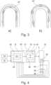
- Figure 3 schematically shows two exemplary reference trajectories RT (cf. Figure 3 a) and Figure 3 b) ) which have been generated by the method for generating a reference trajectory RT within a lane for a vehicle V as described above.
- the vehicle V is able to reliably follow these reference trajectories RT.
- both Figure 3 a) and Figure 3 b) also show a dotted line representing the middle of the respective lane, i.e. a trajectory always having an identical lateral distance from the border of the lane on both sides.
- the minimization of the power loss P loss results in the minimization of the travel distance.
- the reference trajectory RT has a minimum length which of course respects boundary conditions such as the drivable area and the minimum lateral margins.
- the lateral tire slip loss is comparatively high.
- the corresponding kind of loss is reduced by increasing the curve radius of the reference trajectory RT.
- the reference trajectory RT minimizing the power loss maximizes the curve radius. This leads to the fact that the reference trajectory RT being calculated by the method as described above is longer than a reference trajectory following the middle of the lane (cf. dotted line).
- Figure 4 shows a data processing apparatus 10 comprising first means 12 for carrying out the method for generating a reference trajectory RT within a lane for a vehicle V.
- the data processing apparatus 10 comprises second means 14 for providing a control signal for controlling a motion of the vehicle V along the reference trajectory RT.
- the control signal relates to a steering angle ⁇ of a steering system 16 of the vehicle V.
- the first means 12 and the second means 14 together form a third means 18 for carrying out the method for operating the vehicle V.
- the first means 12 comprises a data processing unit 20, e.g. a computer, on which a computer program product may be executed.
- a data processing unit 20 e.g. a computer, on which a computer program product may be executed.
- the computer program product comprises instructions which, when the program is executed by the data processing unit 20, cause the data processing unit 20 to carry out the method for generating a reference trajectory RT within a lane for a vehicle V.
- the first means 12 additionally comprise a computer-readable medium 22 which may also be designated a storage unit.
- the computer-readable medium 22 comprises instructions which, when executed by the data processing unit 20, cause the data processing unit 20 to carry out the method for generating a reference trajectory RT within a lane for a vehicle V.
- the data processing unit 20 and the computer-readable medium 22 interact with each other in order to generate the reference trajectory RT, i.e. in order to perform the method for generating a reference trajectory RT within a lane for a vehicle V.
- the first means 12 provides a reference longitudinal position, a reference lateral position, a reference yaw angle, and a reference longitudinal speed over time which describe the reference trajectory RT.
- the second means 14 receives these parameters describing the reference trajectory RT as an input.
- the second means 14 comprises a data processing unit 24, e.g. a computer, on which a computer program product may be executed.
- the computer program product comprises instructions which, when the program is executed by the data processing unit 24, cause the data processing unit 24 to provide a control signal for controlling a motion of the vehicle V along the reference trajectory RT which is a control signal relating to the steering angle ⁇ in the present disclosure.
- the second means 14 additionally comprise a computer-readable medium 26 which may also be designated a storage unit.
- the computer-readable medium 26 comprises instructions which, when executed by the data processing unit 24, cause the data processing unit 24 to provide the control signal.
- the data processing unit 24 and the computer-readable medium 26 interact with each other in order to provide the control signal.
- the second means 14 thus provides the steering angle ⁇ as an output which is received by the steering system 16 of the vehicle V.
- the steering system 16 comprises a steering angle sensing unit 32 which is configured for detecting a current steering angle ⁇ .
- the current steering angle ⁇ is fed back to the data processing apparatus 10, more precisely to the second means 14 such that the steering angle ⁇ can be controlled in a closed loop manner.
- the vehicle V comprises a position sensor 34, e.g. using a GPS signal.
- the sensing results of the position sensor 34 are provided to the data processing apparatus 10, especially to the first means 12.
- the position sensor 34 may provide a longitudinal position, a lateral position and a yaw angle of the vehicle V.
- the vehicle V comprises an inertial measurement unit 36 which is able to detect a yaw rate of the vehicle and provide the yaw rate to the data processing apparatus 10, especially to the first means 12.
- the vehicle also comprises a speed sensing unit 38 which is able to detect or estimate a longitudinal speed of the vehicle V.
- the speed sensing unit 38 is configured for providing the detection result to the data processing apparatus 10, especially to the first means 12.
- the steering angle sensing unit 32, the position sensor 34, the inertial measurement unit 36 and the speed sensing unit 38 may be summarized as a sensor unit 40.
- the sensor unit 40 thus is configured for providing vehicle current state parameters describing a current state of the vehicle V to the data processing apparatus 10 and in particular the first means 12.
- the destination parameter and the route parameter may be received from a navigation unit 28
- boundary conditions as described above and generally designated with reference sign 30 may be received.
- the boundary conditions may be stored on the computer-readable media 22, 26.
- a computer program may be stored/distributed on a suitable medium such as an optical storage medium or a solid-state medium supplied together with or as part of other hardware, but may also be distributed in other forms, such as via the Internet or other wired or wireless telecommunication systems. Any reference signs in the claims should not be construed as limiting the scope of the claims.
Landscapes
- Engineering & Computer Science (AREA)
- Automation & Control Theory (AREA)
- Transportation (AREA)
- Mechanical Engineering (AREA)
- Radar, Positioning & Navigation (AREA)
- Remote Sensing (AREA)
- Physics & Mathematics (AREA)
- Mathematical Physics (AREA)
- General Physics & Mathematics (AREA)
- Chemical & Material Sciences (AREA)
- Combustion & Propulsion (AREA)
- Human Computer Interaction (AREA)
- Steering Control In Accordance With Driving Conditions (AREA)
- Control Of Driving Devices And Active Controlling Of Vehicle (AREA)
Abstract
Description
- The present disclosure relates to a method for generating a reference trajectory within a lane for a vehicle.
- Furthermore, the disclosure is directed to a method for operating a vehicle.
- Moreover, the present disclosure is directed to a data processing apparatus comprising means for carrying out the above methods, a vehicle comprising such a data processing apparatus, and a computer-readable medium.
- It is known in the art to operate a vehicle such that it follows a reference trajectory within a lane. In this context, the generation of the reference trajectory may also be designated as path planning or trajectory planning. Thus, the path or trajectory defines where on a road or within a lane the vehicle is to be driven. A lane sometimes is also called a traffic lane or a track. In contrast thereto, a route for the vehicle defines which road or lane is to be taken.
- A trajectory generally describes a series of positions for the vehicle, in more detail a series of longitudinal and lateral positions. The positions may by interpolated such that the trajectory is a curve.
- Trajectories need to be generated for both autonomous vehicles and vehicles being driven by a human driver having advanced driver assistance systems, especially lane assistance. The latter may also be designated partially autonomous vehicles.
- In known methods, the reference trajectory is generated such that it generally is located in the center of the lane. In doing so, the margins between the sides of the vehicle and the border of the lane are of substantially equal size on both sides. This ensures safe travelling of the vehicle and high comfort for the driver and the passengers.
- It is an object of the present disclosure to improve such methods.
- The problem is at least partially solved or alleviated by the subject matter of the independent claims of the present disclosure, wherein further examples are incorporated in the dependent claims.
- According to a first aspect, there is provided a method for generating a reference trajectory within a lane for a vehicle, comprising:
- receiving at least one vehicle current state parameter describing a current state of the vehicle, wherein the current state of the vehicle comprises at least a current position of the vehicle,
- receiving a destination parameter describing a destination to be reached by the vehicle,
- receiving at least one route parameter describing a route starting at the current position of the vehicle (V) and ending at the destination,
- estimating a power loss being caused when traveling from the current position of the vehicle to the destination, the power loss being a function of at least one vehicle state parameter describing a state of the vehicle along the route, the destination parameter and a traveling time, and
- determining the reference trajectory within the lane that minimizes the power loss and leads to the destination.
- The current state parameter and/or the destination parameter and/or the route parameter may be received from a navigation unit. The navigation unit may be configured for calculating a route leading the vehicle from a current position to a destination. By estimating a power loss and by determining the reference trajectory which minimizes the power loss, the energy efficiency of the vehicle is increased when the vehicle travels along the reference trajectory. Consequently, the driving range of the vehicle is increased. This is the case for both electric vehicles and vehicles being powered by an internal combustion engine. Moreover, the direct or indirect emissions per distance unit of the vehicle are reduced.
- In the present disclosure, a power loss represents power that was intended to fulfill a vehicle motion request but has not been used thereto and is thus lost.
- The general idea underlying the present disclosure is to consider the energy efficiency when generating a reference trajectory.
- In an example, the vehicle current state parameter and the vehicle state parameter each comprise at least one of a corresponding longitudinal position of the vehicle, a corresponding lateral positon of the vehicle, a corresponding yaw angle of the vehicle, a corresponding longitudinal speed of the vehicle, a corresponding side-slip angle of the vehicle and a corresponding yaw rate of the vehicle. Thus, the vehicle current state parameter and the vehicle state parameter may relate to the same properties, however the corresponding values may be different. Sometimes, the longitudinal position of the vehicle is designated as a position along a X axis and the lateral positon is designated as a position along a Y axis. In this context, a yaw angle is measured around a Z axis. The X, Y and Z axes are perpendicular to one another. The side slip angle is the angle between the vehicle longitudinal direction and the traveling direction of the vehicle's center of gravity. Consequently, the vehicle current state can be described with high precision. This also applies to a vehicle state in general and the vehicle state as it evolves along the route.
- According to an example, the reference trajectory is described by at least one of a reference longitudinal position, a reference lateral position, a reference yaw angle, a reference longitudinal speed and time. In this context, time may be travelling time. Thus, the reference trajectory is described in a simple and computationally efficient manner. It is understood that the reference longitudinal position, the reference lateral position, the reference yaw angle, and the reference longitudinal speed are provided as functions over time.
- In an example, the power loss comprises at least one of a propulsion loss, a transmission loss, a tire loss and a drag loss. Thus, the power loss can be calculated with high precision. In this context, the propulsion loss may comprise losses occurring in the electric motor used for propelling the vehicle and the corresponding inverter unit. Of course, also a plurality of electric motors and/or a plurality of inverter units may be used. The transmission loss comprises losses occurring in a transmission. The tire loss may comprise losses occurring at the interface of the tires and the road.
- In an example, the propulsion loss may be determined on a test bench where the at least one electric motor and the at least one inverter unit are operated in one or more operational points. The operational points are for example characterized by a torque which is provided by the electric motor. If the at least one electric motor and the at least one inverter unit are operated in more than one operational points, a curve describing the propulsion loss as a function of the provided torque can be generated using a curve fit technique. In an example, the curve fit uses a quadratic function.
- In an example, the transmission loss may be determined on a test bench where the transmission is operated in one or more operational points. The operational points are for example characterized by a torque which is provided at an output of the transmission. If the transmission is operated in more than one operational points, a curve describing the transmission loss as a function of the provided torque can be generated using a curve fit technique. In an example, the curve fit uses a quadratic function.
- In an example, the tire loss may comprise at least one of a longitudinal slip loss, a lateral slip loss and a rolling resistance power loss. The longitudinal slip loss and the lateral slip loss may be calculated by multiplying a corresponding longitudinal or lateral force with the corresponding slip velocity.
- In an example, the drag loss may be calculated as a function of a drag coefficient, the density of air and the speed of the vehicle.
- In an example, estimating the power loss comprises using a predefined power loss function. In the context of an optimization problem, the predefined power loss function is a so-called "cost function". Once the types of power losses to be considered are determined, the formulae describing these losses may be combined into the predefined power loss function. This is computationally efficient. Thus, the power loss may be derived in a reliable manner.
- In an example, the method may comprise integrating the power loss over time in order to calculate an energy loss. Thus, an energy loss may be easily calculated. When integrating the power losses over the traveling time, an energy loss of a drive cycle may be determined and minimized in accordance with the present method.
- In an example, determining the reference trajectory may comprise respecting at least one of a drivable area, a desired speed, a minimum lateral margin, a maximum allowable side slip angle, a maximum available torque, and a road friction coefficient as a boundary condition. An alternative term for boundary condition is constraint. The drivable area designates the area of the lane on which the vehicle may drive. The drivable area may be defined within the same plane as a longitudinal and lateral position of the vehicle. The desired speed describes the driving behavior or the human or autonomous driver. The lateral margins need to be respected in order to avoid collisions with vehicles or objects on neighboring lanes. The maximum allowable side slip angle guarantees that the vehicle stays stable and controllable. The maximum available torque is a characteristic of a propulsion system of the vehicle. By respecting at least one of the above boundary conditions, a realistic and safe reference trajectory is determined.
- In an example, at least one of the drivable area, the desired speed, the minimum lateral margin, the maximum allowable side slip angle, the maximum available torque, and the road friction coefficient is known or received. The drivable area may be received from the navigation unit. Alternatively or additionally, the drivable area may be received from a camera unit being configured for detecting a drivable area of a lane ahead of the vehicle. The desired speed may be derived from a speed limit being for example provided by the navigation unit. Alternatively or additionally, the desired speed may be derived from historic drive data. In a very simple case the desired speed is the historic average speed. The minimum lateral margin may be provided as a function of speed. The road friction coefficient may be received from a table or map of road coefficients. The road friction coefficient may also be derived from a classification of the corresponding road, e.g. highway or city road. The classification of the relevant road may be provided by the navigation unit. In a very simple case a standard parameter may be used as the road friction coefficient. Thus, the parameters being used as boundary conditions can be provided in a simple and reliable manner.
- In an example, the method comprises receiving the at least one vehicle current state parameter from a sensor unit. This is a simple and reliable way to use up-to-date input parameters when performing the method.
- According to a second aspect, there is provided a method for operating a vehicle, comprising:
- generating a reference trajectory according to the present disclosure,
- providing at least one control signal for controlling a motion of the vehicle along the reference trajectory.
- Thus, the vehicle may be operated to follow the reference trajectory. Consequently, the power loss occurring while traveling along the reference trajectory is minimized. In other words, the energy efficiency of the vehicle is increased. This leads to an increased driving range of the vehicle. Also corresponding emissions per distance unit of the vehicle may be reduced.
- In an example, the method for operating a vehicle is implemented as a closed loop control method. In this context, one or more sensors may be used to determine a potential deviation of the vehicle from the reference trajectory. The sensors may comprise at least one of an inertial measurement unit for determining a yaw rate, a vehicle speed sensor for determining a vehicle speed and a positioning sensor, e.g. a GPS sensor, for determining a position of the vehicle. The control may be performed in real time.
- In an example, the control signal may comprise a steering angle control signal. Using such a signal, the vehicle can be operated such that it follows the reference trajectory without or with a minimal deviation only.
- In an example, the method comprises performing a pure pursuit control technique for controlling steering angle. Thus, the desired steering angle can be set with high reliability.
- The method for generating a reference trajectory within a lane for a vehicle and/or the method for operating a vehicle may be at least partly computer-implemented, and may be implemented in software or in hardware, or in software and hardware.
- According to a third aspect there is provided a data processing apparatus comprising means for carrying out the method according to the disclosure. The data processing means may be a suitable computing means, such as an electronic control module etc., which may also be a distributed computer system. The data processing means or the computer, respectively, may comprise one or more of a processor, a memory, a data interface, or the like.
- According to a fourth aspect there is provided a vehicle comprising a data processing apparatus according to the third aspect of the present disclosure.
- According to a fifth aspect, there is provided a computer-readable medium comprising instructions which, when executed by a data processing unit, cause the data processing unit to carry out the method of the present disclosure.
- In an example, the data processing unit may be a computer.
- It should be noted that the above examples may be combined with each other irrespective of the aspect involved.
- These and other aspects of the present disclosure will become apparent from and elucidated with reference to the examples described hereinafter.
- Examples of the disclosure will be described in the following with reference to the following drawings.
- Fig. 1
- shows steps of a method according to the present disclosure for generating a reference trajectory within a lane for a vehicle and of a method according to the present disclosure for operating a vehicle,
- Fig. 2
- illustrates a pure pursuit control technique for controlling a steering angle,
- Fig. 3
- schematically shows two exemplary reference trajectories which have been generated by the method for generating a reference trajectory within a lane for a vehicle of
Figure 1 , and - Fig. 4
- schematically shows a data processing apparatus according to the present disclosure comprising means for carrying out the methods of
Figure 1 . - The figures are merely schematic representations and serve only to illustrate examples of the disclosure. Identical or equivalent elements are in principle provided with the same reference signs.
-
Figure 1 shows a method for generating a reference trajectory RT within a lane for a vehicle V comprising steps S11 to S15 and a method for operating a vehicle comprising steps S21 and S22 (see alsoFigure 3 ). - Step S11 of the method for generating a reference trajectory RT within a lane for a vehicle V comprises receiving at least one vehicle current state parameter describing a current state of the vehicle.
- In the example as shown in the figures, the current state of the vehicle V is described by a position of the vehicle. Thus, in step S11, a longitudinal position of the vehicle, a lateral positon of the vehicle, and a yaw angle of the vehicle are received. These vehicle current state parameters may be expressed in a vehicle coordinate system, i.e. a coordinate system having its origin on the vehicle. Alternatively, a global coordinate system may be used.
- Additionally, the current state of the vehicle may be described by a longitudinal speed of the vehicle, a side-slip angle of the vehicle or a yaw rate of the vehicle. Also these vehicle current state parameters may be expressed in a vehicle coordinate system or a global coordinate system.
- The parameters describing the vehicle current state may be received from a navigation unit using GPS data. More generally, the vehicle current state parameters are received from as sensor unit.
- Step S12 comprises receiving a destination parameter. The destination parameter describes a destination to be reached by the vehicle. The destination parameter may describe a position. Also the destination parameter may be received from a navigation unit using for example GPS data.
- A further step S13 comprises receiving at least one route parameter. The route parameter describes a route starting at the current position of the vehicle V and ending at the destination, i.e. a route leading from the current position of the vehicle to the destination. As has been described before, a route defines which road or lane is to be taken.
- It is obvious that the vehicle current state and the destination parameter need to be known in order to be able to calculate the at least one route parameter. However, of course different routes may be available for connecting a vehicle having a current state and a destination.
- Thereafter, a step S14 comprises estimating a power loss Ploss being caused when traveling from the current position of the vehicle V to the destination along the route.
- The power loss Ploss is a function of at least one vehicle state parameter describing a state of the vehicle along the route, the destination parameter and a traveling time.
- The estimated power loss Ploss comprises a propulsion loss, a transmission loss, a tire loss and a drag loss.
- In the present example, the propulsion loss PP,loss describes a loss occurring in a propulsion system of the vehicle V, e.g. in an electric motor and a corresponding inverter unit. The propulsion loss PP,loss is estimated as a function of the delivered propulsion torque T. It is assumed that the propulsion loss PP,loss may be described by a quadratic function over the torque T which reads as follows:

- The parameters a1, a2, a3 depend from a rotational speed of the propulsion motor which may be an electric motor.
- The propulsion loss PP,loss is assessed on a test bench using several operational points of the propulsion system. The parameters a1, a2, a3 of the above formula are determined by performing a curve fit.
- The transmission loss PT,loss comprises a loss occurring in a transmission. The transmission loss PT,loss is also described by a quadratic function over torque T. As before, the transmission loss PT,loss is assessed on a test bench by operating the transmission in a number of operational points. Subsequently, a quadratic curve fit is performed. Consequently, the transmission loss PT,loss can be described by the following formula:

- The parameters b1, b2, b3 depend from a rotational speed of the transmission and are determined when performing the curve fit.
- In the present example, one component of the tire loss PTi,loss is assumed to be a longitudinal slip loss PSx,loss. The longitudinal slip loss PSx,loss is calculated using the following formula, wherein the longitudinal slip loss of each of the four wheels i=1 to i=4 of the vehicle are cumulated:

- In this formula, Fxi is the longitudinal force acting on wheel i in the x direction.
- The longitudinal velocity of the center of the wheel i, i.e. the velocity of the center of the wheel i along the x direction is denoted vxwi. The parameter rei is the effective radius of the wheel i and ωi is the rotational velocity of the wheel i.
- If a linear tire model is used and the resulting expression is linearized, the above formula can be rewritten as follows:

- In this formula Cxj is the longitudinal tire stiffness of the tires of axle j. The parameter ni is the rotational speed of the respective wheel i of the axle and Tmi is the torque transmitted by the wheel i. The parameter vxi is the longitudinal velocity of the wheel i. The parameter rei again relates to the effective radius of the wheel i.
- Another component of the tire loss PTi,loss is assumed to be a lateral slip loss PSy,loss. The lateral slip loss PSy,loss can be calculated as follows:

- In this expression Fyi is the lateral force acting on wheel i. The parameter vyi is the lateral velocity of the wheel i and vxi is the longitudinal velocity of the wheel i. δi is the steering angle of wheel i.
- If again a linear tire model is used and the resulting expression is linearized, the above formula can be rewritten as follows:

- In this expression, Cyi is the lateral tire stiffness of the wheel i and αi is the tire slip angle of the wheel i. vx is the longitudinal velocity of the vehicle.
- An additional component of the tire loss is the rolling resistance power loss PRR,loss which may be calculated as follows:

- In the above formula, the parameters r0, q1, q2, q3, q4, vref and Fz0 are obtained through tire measurements. Fzi is a force acting on the wheel i in the z direction. As before, vxi is the longitudinal velocity of the wheel i, Fxi is the longitudinal force acting on wheel i in the x direction, and ωi is the rotational velocity of the wheel i.
- Thus, the tire loss PTi,loss is the sum of the longitudinal slip loss PSx,loss, the lateral slip loss PSy,loss, and the rolling resistance power loss PRR,loss.
- As has been mentioned above, the drag loss PD,loss may be calculated as a function of a drag coefficient, the density of air and the speed of the vehicle.
- The different types of losses may be summed up in a power loss function. Thus, estimating the power loss Ploss comprises using a predefined power loss function.
- In case the energy losses are of interest, the power loss Ploss may be integrated over time. The result is an energy loss occurring during the integration time. The integration time may be the travelling time.
- Once, the power loss function is known, in step S15 a reference trajectory RT may be determined which minimizes the power loss function.
- The reference trajectory RT may be described by a reference longitudinal position along direction x, a reference lateral position along a direction y, and a reference yaw angle ψ. In the present example, the reference longitudinal position, the reference lateral position, and the reference yaw angle are functions over traveling time.
- Additionally, the reference trajectory RT may be described by a reference longitudinal speed.
- It is understood that the above minimization problem is subject to several boundary conditions.
- First of all, the reference trajectory RT must lead to the destination.
- Furthermore, the reference trajectory RT must not exit the drivable lanes of the route. In other words, a drivable area needs to be respected. The vehicle V must stay within the drivable area at all time.
- In order to allow safe travelling of the vehicle V, also minimum lateral margins with respect to a border of the drivable area must be respected.
- A further boundary condition may relate to a maximum allowable side slip angle. This parameter may be chosen such that the vehicle stays stable and controllable at any time.
- Moreover, a maximum available torque may be respected which is a characteristic of the propulsion unit and especially a propulsion motor of the vehicle V.
- An additional boundary condition may relate to a road friction coefficient.
- Furthermore, a desired speed may be respected as a boundary condition. The desired speed may be described by an allowable maximum speed and an allowable minimum average speed.
- It is noted that the desired speed is used for calculating the reference trajectory only. The actual speed when driving along the reference trajectory may differ therefrom.
- In the example shown in the figures, the above-mentioned boundary conditions are known, i.e. provided by a storage unit of the vehicle.
- The reference trajectory may be used in a method for operating a vehicle comprising steps S21 and S22.
- Step S21 relates to the generation of the reference trajectory RT and comprises steps S11 to S15.
- Step S22 comprises providing at least one control signal for controlling a motion of the vehicle along the reference trajectory.
- In the present example, the control signal comprises a steering angle control signal. This means that the steering angle δ of the vehicle is controlled such that the vehicle follows the reference trajectory RT.
- To this end, a pure pursuit control technique may be performed for controlling the steering angle δ.
- This control technique is explained in connection with
Figure 2 , where a vehicle V having a length L is shown. - The vehicle V intends to follow the reference trajectory RT which is represented as a straight line in
Figure 2 for the ease of explanation. It is understood that the reference trajectory RT could as well be curved which is closer to reality than a straight reference trajectory. - The pure pursuit control technique is a geometric path tracking control technique which uses only the geometry of the vehicle kinematics and the reference trajectory. The pure pursuit control technique ignores dynamic forces and assumes a no-slip condition of the vehicle.
- In this context, a target point TP on the reference trajectory RT is used. The target point TP is ahead of the vehicle V at a fixed and known distance ld from the vehicle. The distance ld may be called a look ahead distance.
- An angle between the direction of ld and the direction of the length L of the vehicle V is designated β. Also β is known and may be called a look ahead angle.
- The objective is to steer the vehicle to the target point TP. To this end, the vehicle V would need to travel along curve C which has a radius R and a center point M.
- In this context, a center of the rear axle of the vehicle is used as reference point on the vehicle. This point, the center point M and the target point TP form a triangle.
- The portion of the reference trajectory being located within this triangle has a length l0 which can be expressed as follows:


- This results in the following equation

- This equation can be rewritten as

- The so-called bicycle model provides the following dependency of the radius R, the length of the vehicle L and the steering angle δ:

- Thus, the steering angle δ can be expressed as

- It is noted that the look ahead distance ld can be varied based on the vehicle speed.
-
Figure 3 schematically shows two exemplary reference trajectories RT (cf.Figure 3 a) and Figure 3 b) ) which have been generated by the method for generating a reference trajectory RT within a lane for a vehicle V as described above. Using the pure pursuit control technique, the vehicle V is able to reliably follow these reference trajectories RT. - In order to illustrate the difference over known reference trajectories, both
Figure 3 a) and Figure 3 b) also show a dotted line representing the middle of the respective lane, i.e. a trajectory always having an identical lateral distance from the border of the lane on both sides. - In the example of
Figure 3 a) , the minimization of the power loss Ploss results in the minimization of the travel distance. Thus, in this example, the reference trajectory RT has a minimum length which of course respects boundary conditions such as the drivable area and the minimum lateral margins. - In the example of
Figure 3 b) the lateral tire slip loss is comparatively high. The corresponding kind of loss is reduced by increasing the curve radius of the reference trajectory RT. Thus, in this example, the reference trajectory RT minimizing the power loss maximizes the curve radius. This leads to the fact that the reference trajectory RT being calculated by the method as described above is longer than a reference trajectory following the middle of the lane (cf. dotted line). -
Figure 4 shows adata processing apparatus 10 comprising first means 12 for carrying out the method for generating a reference trajectory RT within a lane for a vehicle V. - Moreover, the
data processing apparatus 10 comprises second means 14 for providing a control signal for controlling a motion of the vehicle V along the reference trajectory RT. In the present example, the control signal relates to a steering angle δ of asteering system 16 of the vehicle V. - The first means 12 and the second means 14 together form a third means 18 for carrying out the method for operating the vehicle V.
- In more detail, the first means 12 comprises a
data processing unit 20, e.g. a computer, on which a computer program product may be executed. - The computer program product comprises instructions which, when the program is executed by the
data processing unit 20, cause thedata processing unit 20 to carry out the method for generating a reference trajectory RT within a lane for a vehicle V. - The first means 12 additionally comprise a computer-
readable medium 22 which may also be designated a storage unit. The computer-readable medium 22 comprises instructions which, when executed by thedata processing unit 20, cause thedata processing unit 20 to carry out the method for generating a reference trajectory RT within a lane for a vehicle V. - The
data processing unit 20 and the computer-readable medium 22 interact with each other in order to generate the reference trajectory RT, i.e. in order to perform the method for generating a reference trajectory RT within a lane for a vehicle V. - As an output, the first means 12 provides a reference longitudinal position, a reference lateral position, a reference yaw angle, and a reference longitudinal speed over time which describe the reference trajectory RT.
- The second means 14 receives these parameters describing the reference trajectory RT as an input.
- In more detail, the second means 14 comprises a
data processing unit 24, e.g. a computer, on which a computer program product may be executed. - The computer program product comprises instructions which, when the program is executed by the
data processing unit 24, cause thedata processing unit 24 to provide a control signal for controlling a motion of the vehicle V along the reference trajectory RT which is a control signal relating to the steering angle δ in the present disclosure. - The second means 14 additionally comprise a computer-
readable medium 26 which may also be designated a storage unit. The computer-readable medium 26 comprises instructions which, when executed by thedata processing unit 24, cause thedata processing unit 24 to provide the control signal. - The
data processing unit 24 and the computer-readable medium 26 interact with each other in order to provide the control signal. - The second means 14 thus provides the steering angle δ as an output which is received by the
steering system 16 of the vehicle V. - The
steering system 16 comprises a steeringangle sensing unit 32 which is configured for detecting a current steering angle δ. - The current steering angle δ is fed back to the
data processing apparatus 10, more precisely to the second means 14 such that the steering angle δ can be controlled in a closed loop manner. - Moreover, the vehicle V comprises a
position sensor 34, e.g. using a GPS signal. The sensing results of theposition sensor 34 are provided to thedata processing apparatus 10, especially to thefirst means 12. Theposition sensor 34 may provide a longitudinal position, a lateral position and a yaw angle of the vehicle V. - Additionally, the vehicle V comprises an
inertial measurement unit 36 which is able to detect a yaw rate of the vehicle and provide the yaw rate to thedata processing apparatus 10, especially to thefirst means 12. - The vehicle also comprises a
speed sensing unit 38 which is able to detect or estimate a longitudinal speed of the vehicle V. Thespeed sensing unit 38 is configured for providing the detection result to thedata processing apparatus 10, especially to thefirst means 12. - The steering
angle sensing unit 32, theposition sensor 34, theinertial measurement unit 36 and thespeed sensing unit 38 may be summarized as a sensor unit 40. - The sensor unit 40 thus is configured for providing vehicle current state parameters describing a current state of the vehicle V to the
data processing apparatus 10 and in particular thefirst means 12. - The destination parameter and the route parameter may be received from a
navigation unit 28 - Also boundary conditions as described above and generally designated with
reference sign 30 may be received. Alternatively, the boundary conditions may be stored on the computer-readable media - Other variations to the disclosed examples can be understood and effected by those skilled in the art in practicing the claimed disclosure, from the study of the drawings, the disclosure, and the appended claims. In the claims the word "comprising" does not exclude other elements or steps and the indefinite article "a" or "an" does not exclude a plurality. A single processor or other unit may fulfill the functions of several items or steps recited in the claims. The mere fact that certain measures are recited in mutually different dependent claims does not indicate that a combination of these measures cannot be used to advantage. A computer program may be stored/distributed on a suitable medium such as an optical storage medium or a solid-state medium supplied together with or as part of other hardware, but may also be distributed in other forms, such as via the Internet or other wired or wireless telecommunication systems. Any reference signs in the claims should not be construed as limiting the scope of the claims.
-
- 10
- data processing apparatus
- 12
- first means
- 14
- second means
- 16
- steering system
- 18
- third means
- 20
- data processing unit
- 22
- computer-readable medium
- 24
- data processing unit
- 26
- computer-readable medium
- 28
- navigation unit
- 30
- boundary condition
- 32
- steering angle sensing unit
- 34
- position sensor
- 36
- inertial measurement unit
- 38
- speed sensing unit
- 40
- sensor unit
- a1
- parameter
- a2
- parameter
- a3
- parameter
- b1
- parameter
- b2
- parameter
- b3
- parameter
- C
- curve
- Cxj
- longitudinal tire stiffness of the tires of axle j
- Cyi
- lateral tire stiffness of the wheel i
- Fxi
- longitudinal force on wheel i
- Fyi
- lateral force on wheel i
- Fzi
- force acting on the wheel i in the z direction
- Fz0
- parameter obtained through tire measurement
- i
- wheel index
- j
- axle index
- l0
- length
- ld
- look ahead distance
- M
- center point
- n;
- rotational speed of the wheel i
- Ploss
- power loss
- PD,loss
- drag loss
- PP,loss
- propulsion loss
- PTi,loss
- tire loss
- PSx,loss
- longitudinal slip loss
- PSy,loss
- lateral slip loss
- PT,loss
- transmission loss
- PRR,loss
- rolling resistance power loss
- q1
- parameter obtained through tire measurement
- q2
- parameter obtained through tire measurement
- q3
- parameter obtained through tire measurement
- q4
- parameter obtained through tire measurement
- R
- radius
- r0
- parameter obtained through tire measurement
- rei
- effective radius of the wheel i
- RT
- reference trajectory
- S11
- method step
- S12
- method step
- S13
- method step
- S14
- method step
- S15
- method step
- S21
- method step
- S22
- method step
- T
- propulsion torque
- Tmi
- torque transmitted by wheel i.
- TP
- target point
- V
- vehicle
- vref
- parameter obtained through tire measurement
- vxi
- longitudinal velocity of the wheel i
- vxwi
- velocity of the center of the wheel i along the x direction
- vyi
- lateral velocity of the wheel i
- x
- longitudinal direction
- y
- lateral direction
- αi
- tire slip angle of the wheel i
- β
- look ahead angle
- δ
- steering angle
- δi
- steering angle of wheel i
- ψ
- yaw angle
- ωi
- rotational velocity of the wheel i
Claims (15)
- A method for generating a reference trajectory (RT) within a lane for a vehicle (V), comprising:- receiving at least one vehicle current state parameter describing a current state of the vehicle (V) (S11), wherein the current state of the vehicle (V) comprises at least a current position of the vehicle (V),- receiving a destination parameter describing a destination to be reached by the vehicle (V) (S12),- receiving at least one route parameter describing a route starting at the current position of the vehicle (V) and ending at the destination (S13),- estimating a power loss (Ploss) being caused when traveling from the current position of the vehicle (V) to the destination, the power loss (Ploss) being a function of at least one vehicle state parameter describing a state of the vehicle along the route, the destination parameter and a traveling time (S14), and- determining the reference trajectory (RT) within the lane that minimizes the power loss (Ploss) and leads to the destination (S15).
- The method according to claim 1, wherein the vehicle current state parameter and the vehicle state parameter each comprise at least one of a corresponding longitudinal position of the vehicle (V), a corresponding lateral positon of the vehicle (V), a corresponding yaw angle (ψ) of the vehicle, a corresponding longitudinal speed of the vehicle (V), a corresponding side-slip angle of the vehicle (V) and a corresponding yaw rate of the vehicle (V).
- The method according to claim 1 or 2, wherein the reference trajectory (RT) is described by at least one of a reference longitudinal position, a reference lateral position, a reference yaw angle, a reference longitudinal speed and time.
- The method according to any one of the preceding claims, wherein the power loss (Ploss) comprises at least one of a propulsion loss (PP,loss), a transmission loss (PT,loss), a tire loss (PTi,loss) and a drag loss (PD,loss).
- The method according to any one of the preceding claims, wherein estimating the power loss (Ploss) comprises using a predefined power loss function.
- The method according to any one of the preceding claims, comprising: integrating the power loss (Ploss) over time in order to calculate an energy loss.
- The method according to any one of the preceding claims, wherein determining the reference trajectory (RT) comprises: respecting at least one of a drivable area, a desired speed, a minimum lateral margin, a maximum allowable side slip angle, a maximum available torque, and a road friction coefficient as a boundary condition.
- The method according to claim 7, wherein at least one of the drivable area, the desired speed, the minimum lateral margin, the maximum allowable side slip angle, the maximum available torque, and the road friction coefficient is known or received.
- The method according to any one of the preceding claims, comprising: receiving the at least one vehicle current state parameter from a sensor unit (40).
- A method for operating a vehicle (V), comprising:- generating a reference trajectory (RT) according to any one of the preceding claims,- providing at least one control signal for controlling a motion of the vehicle (V) along the reference trajectory (RT).
- The method according to claim 10, wherein the control signal comprises a steering angle control signal.
- The method according to claim 11, comprising: performing a pure pursuit control technique for controlling the steering angle (δ).
- A data processing apparatus (10) comprising means (12, 14, 18) for carrying out the method according to any one of the preceding claims.
- A vehicle (V) comprising a data processing apparatus (10) according to claim 13.
- A computer-readable medium (22) comprising instructions which, when executed by a data processing unit (20), cause the data processing unit (20) to carry out the method of any one of claims 1 to 12.
Priority Applications (3)
| Application Number | Priority Date | Filing Date | Title |
|---|---|---|---|
| EP22153686.5A EP4220329A1 (en) | 2022-01-27 | 2022-01-27 | Method for generating a reference trajectory within a lane, method for operating a vehicle, data processing apparatus, vehicle, and computer-readable medium |
| CN202310076539.4A CN116494970A (en) | 2022-01-27 | 2023-01-17 | Method for generating reference trajectory in lane, method for operating vehicle |
| US18/158,524 US12442649B2 (en) | 2022-01-27 | 2023-01-24 | Method for generating a reference trajectory within a lane, method for operating a vehicle, data processing apparatus, vehicle, and computer-readable medium |
Applications Claiming Priority (1)
| Application Number | Priority Date | Filing Date | Title |
|---|---|---|---|
| EP22153686.5A EP4220329A1 (en) | 2022-01-27 | 2022-01-27 | Method for generating a reference trajectory within a lane, method for operating a vehicle, data processing apparatus, vehicle, and computer-readable medium |
Publications (1)
| Publication Number | Publication Date |
|---|---|
| EP4220329A1 true EP4220329A1 (en) | 2023-08-02 |
Family
ID=80121786
Family Applications (1)
| Application Number | Title | Priority Date | Filing Date |
|---|---|---|---|
| EP22153686.5A Withdrawn EP4220329A1 (en) | 2022-01-27 | 2022-01-27 | Method for generating a reference trajectory within a lane, method for operating a vehicle, data processing apparatus, vehicle, and computer-readable medium |
Country Status (3)
| Country | Link |
|---|---|
| US (1) | US12442649B2 (en) |
| EP (1) | EP4220329A1 (en) |
| CN (1) | CN116494970A (en) |
Cited By (1)
| Publication number | Priority date | Publication date | Assignee | Title |
|---|---|---|---|---|
| SE548064C2 (en) * | 2024-09-20 | 2026-02-17 | Volvo Truck Corp | Computer system and method for estimating lateral slip losses in a vehicle combination |
Families Citing this family (1)
| Publication number | Priority date | Publication date | Assignee | Title |
|---|---|---|---|---|
| SE2450942A1 (en) * | 2024-09-20 | 2026-02-17 | Volvo Truck Corp | Computer system and method for determining steering angles for a trailing unit of a vehicle combination |
Citations (2)
| Publication number | Priority date | Publication date | Assignee | Title |
|---|---|---|---|---|
| US20190107406A1 (en) * | 2017-10-09 | 2019-04-11 | Nio Usa, Inc. | Systems and methods for trip planning under uncertainty |
| US20210373566A1 (en) * | 2020-05-29 | 2021-12-02 | Zoox, Inc. | Trajectory generation using lateral offset biasing |
Family Cites Families (13)
| Publication number | Priority date | Publication date | Assignee | Title |
|---|---|---|---|---|
| DE502004008154D1 (en) * | 2003-05-08 | 2008-11-13 | Continental Teves Ag & Co Ohg | METHOD AND DEVICE FOR REGULATING THE DRIVING DYNAMICS OF A VEHICLE |
| JP6217931B2 (en) * | 2014-07-23 | 2017-10-25 | マツダ株式会社 | Drive torque distribution control device for four-wheel drive vehicle |
| ITUA20162368A1 (en) * | 2016-04-07 | 2017-10-07 | Drive2Go S R L | System and method of estimating an indication of the driving style of a vehicle |
| WO2019055826A1 (en) * | 2017-09-15 | 2019-03-21 | Cummins, Inc. | Vehicle loss calculation for improved fuel economy |
| SE541795C2 (en) * | 2017-09-22 | 2019-12-17 | Sentient Ip Ab | Method and system for controlling vehicle lane holding |
| US10852737B2 (en) * | 2018-03-22 | 2020-12-01 | Micron Technology, Inc. | Power management, dynamic routing and memory management for autonomous driving vehicles |
| US10831210B1 (en) * | 2018-09-28 | 2020-11-10 | Zoox, Inc. | Trajectory generation and optimization using closed-form numerical integration in route-relative coordinates |
| US11117475B2 (en) * | 2018-10-22 | 2021-09-14 | Woven Planet North America, Inc. | Systems and methods for efficient vehicle control |
| US12195083B2 (en) * | 2019-06-26 | 2025-01-14 | The Regents Of The University Of Michigan | Lane change maneuvers with minimized tire slip |
| US11548512B2 (en) * | 2019-08-23 | 2023-01-10 | Zoox, Inc. | Yield behavior modeling and prediction |
| US20210131812A1 (en) * | 2019-11-04 | 2021-05-06 | Ford Global Technologies, Llc | System and method for route based optimization for battery electric vehicles |
| FI20205114A1 (en) * | 2020-02-04 | 2021-08-05 | Roadcloud Oy | Determining and using path specific rolling resistance data for controlling vehicles |
| KR102378313B1 (en) * | 2021-07-23 | 2022-03-24 | 국민대학교산학협력단 | Control apparatus and method of autonomous vehicle |
-
2022
- 2022-01-27 EP EP22153686.5A patent/EP4220329A1/en not_active Withdrawn
-
2023
- 2023-01-17 CN CN202310076539.4A patent/CN116494970A/en active Pending
- 2023-01-24 US US18/158,524 patent/US12442649B2/en active Active
Patent Citations (2)
| Publication number | Priority date | Publication date | Assignee | Title |
|---|---|---|---|---|
| US20190107406A1 (en) * | 2017-10-09 | 2019-04-11 | Nio Usa, Inc. | Systems and methods for trip planning under uncertainty |
| US20210373566A1 (en) * | 2020-05-29 | 2021-12-02 | Zoox, Inc. | Trajectory generation using lateral offset biasing |
Non-Patent Citations (2)
| Title |
|---|
| LAL DHANYA S ET AL: "Lateral control of an autonomous vehicle based on Pure Pursuit algorithm", 2017 INTERNATIONAL CONFERENCE ON TECHNOLOGICAL ADVANCEMENTS IN POWER AND ENERGY ( TAP ENERGY), IEEE, 21 December 2017 (2017-12-21), pages 1 - 8, XP033366248, DOI: 10.1109/TAPENERGY.2017.8397361 * |
| TORINSSON JULIETTE ET AL: "Energy reduction by power loss minimisation through wheel torque allocation in electric vehicles: a simulation-based approach", VEHICLE SYSTEM DYNAMICS: INTERNATIONAL JOURNAL OF VEHICLE MECHANICS AND MOBILITY, vol. 60, no. 5, 10 December 2020 (2020-12-10), GB, pages 1488 - 1511, XP055941394, ISSN: 0042-3114, DOI: 10.1080/00423114.2020.1858121 * |
Cited By (2)
| Publication number | Priority date | Publication date | Assignee | Title |
|---|---|---|---|---|
| SE548064C2 (en) * | 2024-09-20 | 2026-02-17 | Volvo Truck Corp | Computer system and method for estimating lateral slip losses in a vehicle combination |
| SE2450941A1 (en) * | 2024-09-20 | 2026-02-17 | Volvo Truck Corp | Computer system and method for estimating lateral slip losses in a vehicle combination |
Also Published As
| Publication number | Publication date |
|---|---|
| US20230236028A1 (en) | 2023-07-27 |
| US12442649B2 (en) | 2025-10-14 |
| CN116494970A (en) | 2023-07-28 |
Similar Documents
| Publication | Publication Date | Title |
|---|---|---|
| US11307040B2 (en) | Map information provision system | |
| Feraco et al. | A local trajectory planning and control method for autonomous vehicles based on the RRT algorithm | |
| CN102495631B (en) | Intelligent control method of driverless vehicle tracking desired trajectory | |
| CN110614998B (en) | A path planning system and method for aggressive assisted driving, obstacle avoidance and lane change | |
| US11345400B2 (en) | Trajectory tracking with four-wheel steering and steering limits | |
| CN107615011B (en) | Parking position setting device and method | |
| US11423777B2 (en) | Traffic sign displaying device | |
| CN101842820B (en) | Travel trace generation method and travel trace generation device | |
| CN112537297B (en) | Lane keeping method and system and vehicle | |
| EP3678110A1 (en) | Method for correcting positional error and device for correcting positional error in driving assistance vehicle | |
| JP7222259B2 (en) | VEHICLE WHEEL LOAD CONTROL METHOD AND WHEEL LOAD CONTROL DEVICE | |
| EP3678113A1 (en) | Travel control method and travel control device for driving-assist vehicle | |
| US12337842B2 (en) | Path-controlling module, associated path-controlling device and associated method | |
| US12442649B2 (en) | Method for generating a reference trajectory within a lane, method for operating a vehicle, data processing apparatus, vehicle, and computer-readable medium | |
| CN106080598A (en) | Goal pace controls in real time | |
| CN114248797A (en) | Vehicle control device and control method | |
| JP2022118550A (en) | Vehicle driving support device | |
| US20230019462A1 (en) | MPC-Based Trajectory Tracking of a First Vehicle Using Trajectory Information on a Second Vehicle | |
| CN113887276A (en) | Image-based forward main target detection method | |
| US20220410889A1 (en) | Ascertaining a Trajectory for a First Vehicle While Taking into Consideration the Drive Behavior of a Second Vehicle | |
| US20230242107A1 (en) | Vehicle control device and vehicle control system | |
| CN102405169A (en) | Vehicle control device | |
| CN115903786B (en) | Path determination method and device, electronic equipment and storage medium | |
| WO2022006089A1 (en) | Four-wheel steering | |
| JP3024964B1 (en) | Vehicle running control device and vehicle using the same |
Legal Events
| Date | Code | Title | Description |
|---|---|---|---|
| PUAI | Public reference made under article 153(3) epc to a published international application that has entered the european phase |
Free format text: ORIGINAL CODE: 0009012 |
|
| STAA | Information on the status of an ep patent application or granted ep patent |
Free format text: STATUS: REQUEST FOR EXAMINATION WAS MADE |
|
| 17P | Request for examination filed |
Effective date: 20221116 |
|
| AK | Designated contracting states |
Kind code of ref document: A1 Designated state(s): AL AT BE BG CH CY CZ DE DK EE ES FI FR GB GR HR HU IE IS IT LI LT LU LV MC MK MT NL NO PL PT RO RS SE SI SK SM TR |
|
| STAA | Information on the status of an ep patent application or granted ep patent |
Free format text: STATUS: EXAMINATION IS IN PROGRESS |
|
| 17Q | First examination report despatched |
Effective date: 20240619 |
|
| 17Q | First examination report despatched |
Effective date: 20240627 |
|
| STAA | Information on the status of an ep patent application or granted ep patent |
Free format text: STATUS: THE APPLICATION IS DEEMED TO BE WITHDRAWN |
|
| 18D | Application deemed to be withdrawn |
Effective date: 20251021 |