EP4220328A1 - Mining machine - Google Patents
Mining machine Download PDFInfo
- Publication number
- EP4220328A1 EP4220328A1 EP21871901.1A EP21871901A EP4220328A1 EP 4220328 A1 EP4220328 A1 EP 4220328A1 EP 21871901 A EP21871901 A EP 21871901A EP 4220328 A1 EP4220328 A1 EP 4220328A1
- Authority
- EP
- European Patent Office
- Prior art keywords
- measured
- sensor
- calculated
- speed
- mining machine
- Prior art date
- Legal status (The legal status is an assumption and is not a legal conclusion. Google has not performed a legal analysis and makes no representation as to the accuracy of the status listed.)
- Pending
Links
Images








Classifications
-
- B—PERFORMING OPERATIONS; TRANSPORTING
- B60—VEHICLES IN GENERAL
- B60W—CONJOINT CONTROL OF VEHICLE SUB-UNITS OF DIFFERENT TYPE OR DIFFERENT FUNCTION; CONTROL SYSTEMS SPECIALLY ADAPTED FOR HYBRID VEHICLES; ROAD VEHICLE DRIVE CONTROL SYSTEMS FOR PURPOSES NOT RELATED TO THE CONTROL OF A PARTICULAR SUB-UNIT
- B60W30/00—Purposes of road vehicle drive control systems not related to the control of a particular sub-unit, e.g. of systems using conjoint control of vehicle sub-units
- B60W30/14—Adaptive cruise control
- B60W30/143—Speed control
-
- B—PERFORMING OPERATIONS; TRANSPORTING
- B60—VEHICLES IN GENERAL
- B60W—CONJOINT CONTROL OF VEHICLE SUB-UNITS OF DIFFERENT TYPE OR DIFFERENT FUNCTION; CONTROL SYSTEMS SPECIALLY ADAPTED FOR HYBRID VEHICLES; ROAD VEHICLE DRIVE CONTROL SYSTEMS FOR PURPOSES NOT RELATED TO THE CONTROL OF A PARTICULAR SUB-UNIT
- B60W30/00—Purposes of road vehicle drive control systems not related to the control of a particular sub-unit, e.g. of systems using conjoint control of vehicle sub-units
- B60W30/18—Propelling the vehicle
- B60W30/18172—Preventing, or responsive to skidding of wheels
-
- B—PERFORMING OPERATIONS; TRANSPORTING
- B60—VEHICLES IN GENERAL
- B60W—CONJOINT CONTROL OF VEHICLE SUB-UNITS OF DIFFERENT TYPE OR DIFFERENT FUNCTION; CONTROL SYSTEMS SPECIALLY ADAPTED FOR HYBRID VEHICLES; ROAD VEHICLE DRIVE CONTROL SYSTEMS FOR PURPOSES NOT RELATED TO THE CONTROL OF A PARTICULAR SUB-UNIT
- B60W30/00—Purposes of road vehicle drive control systems not related to the control of a particular sub-unit, e.g. of systems using conjoint control of vehicle sub-units
- B60W30/18—Propelling the vehicle
- B60W30/188—Controlling power parameters of the driveline, e.g. determining the required power
-
- B—PERFORMING OPERATIONS; TRANSPORTING
- B60—VEHICLES IN GENERAL
- B60W—CONJOINT CONTROL OF VEHICLE SUB-UNITS OF DIFFERENT TYPE OR DIFFERENT FUNCTION; CONTROL SYSTEMS SPECIALLY ADAPTED FOR HYBRID VEHICLES; ROAD VEHICLE DRIVE CONTROL SYSTEMS FOR PURPOSES NOT RELATED TO THE CONTROL OF A PARTICULAR SUB-UNIT
- B60W40/00—Estimation or calculation of non-directly measurable driving parameters for road vehicle drive control systems not related to the control of a particular sub unit, e.g. by using mathematical models
- B60W40/02—Estimation or calculation of non-directly measurable driving parameters for road vehicle drive control systems not related to the control of a particular sub unit, e.g. by using mathematical models related to ambient conditions
- B60W40/06—Road conditions
- B60W40/068—Road friction coefficient
-
- B—PERFORMING OPERATIONS; TRANSPORTING
- B60—VEHICLES IN GENERAL
- B60W—CONJOINT CONTROL OF VEHICLE SUB-UNITS OF DIFFERENT TYPE OR DIFFERENT FUNCTION; CONTROL SYSTEMS SPECIALLY ADAPTED FOR HYBRID VEHICLES; ROAD VEHICLE DRIVE CONTROL SYSTEMS FOR PURPOSES NOT RELATED TO THE CONTROL OF A PARTICULAR SUB-UNIT
- B60W40/00—Estimation or calculation of non-directly measurable driving parameters for road vehicle drive control systems not related to the control of a particular sub unit, e.g. by using mathematical models
- B60W40/02—Estimation or calculation of non-directly measurable driving parameters for road vehicle drive control systems not related to the control of a particular sub unit, e.g. by using mathematical models related to ambient conditions
- B60W40/06—Road conditions
- B60W40/076—Slope angle of the road
-
- B—PERFORMING OPERATIONS; TRANSPORTING
- B60—VEHICLES IN GENERAL
- B60W—CONJOINT CONTROL OF VEHICLE SUB-UNITS OF DIFFERENT TYPE OR DIFFERENT FUNCTION; CONTROL SYSTEMS SPECIALLY ADAPTED FOR HYBRID VEHICLES; ROAD VEHICLE DRIVE CONTROL SYSTEMS FOR PURPOSES NOT RELATED TO THE CONTROL OF A PARTICULAR SUB-UNIT
- B60W40/00—Estimation or calculation of non-directly measurable driving parameters for road vehicle drive control systems not related to the control of a particular sub unit, e.g. by using mathematical models
- B60W40/10—Estimation or calculation of non-directly measurable driving parameters for road vehicle drive control systems not related to the control of a particular sub unit, e.g. by using mathematical models related to vehicle motion
- B60W40/1005—Driving resistance
-
- B—PERFORMING OPERATIONS; TRANSPORTING
- B60—VEHICLES IN GENERAL
- B60W—CONJOINT CONTROL OF VEHICLE SUB-UNITS OF DIFFERENT TYPE OR DIFFERENT FUNCTION; CONTROL SYSTEMS SPECIALLY ADAPTED FOR HYBRID VEHICLES; ROAD VEHICLE DRIVE CONTROL SYSTEMS FOR PURPOSES NOT RELATED TO THE CONTROL OF A PARTICULAR SUB-UNIT
- B60W40/00—Estimation or calculation of non-directly measurable driving parameters for road vehicle drive control systems not related to the control of a particular sub unit, e.g. by using mathematical models
- B60W40/10—Estimation or calculation of non-directly measurable driving parameters for road vehicle drive control systems not related to the control of a particular sub unit, e.g. by using mathematical models related to vehicle motion
- B60W40/105—Speed
-
- B—PERFORMING OPERATIONS; TRANSPORTING
- B60—VEHICLES IN GENERAL
- B60W—CONJOINT CONTROL OF VEHICLE SUB-UNITS OF DIFFERENT TYPE OR DIFFERENT FUNCTION; CONTROL SYSTEMS SPECIALLY ADAPTED FOR HYBRID VEHICLES; ROAD VEHICLE DRIVE CONTROL SYSTEMS FOR PURPOSES NOT RELATED TO THE CONTROL OF A PARTICULAR SUB-UNIT
- B60W40/00—Estimation or calculation of non-directly measurable driving parameters for road vehicle drive control systems not related to the control of a particular sub unit, e.g. by using mathematical models
- B60W40/10—Estimation or calculation of non-directly measurable driving parameters for road vehicle drive control systems not related to the control of a particular sub unit, e.g. by using mathematical models related to vehicle motion
- B60W40/107—Longitudinal acceleration
-
- B—PERFORMING OPERATIONS; TRANSPORTING
- B60—VEHICLES IN GENERAL
- B60W—CONJOINT CONTROL OF VEHICLE SUB-UNITS OF DIFFERENT TYPE OR DIFFERENT FUNCTION; CONTROL SYSTEMS SPECIALLY ADAPTED FOR HYBRID VEHICLES; ROAD VEHICLE DRIVE CONTROL SYSTEMS FOR PURPOSES NOT RELATED TO THE CONTROL OF A PARTICULAR SUB-UNIT
- B60W40/00—Estimation or calculation of non-directly measurable driving parameters for road vehicle drive control systems not related to the control of a particular sub unit, e.g. by using mathematical models
- B60W40/10—Estimation or calculation of non-directly measurable driving parameters for road vehicle drive control systems not related to the control of a particular sub unit, e.g. by using mathematical models related to vehicle motion
- B60W40/11—Pitch movement
-
- B—PERFORMING OPERATIONS; TRANSPORTING
- B60—VEHICLES IN GENERAL
- B60W—CONJOINT CONTROL OF VEHICLE SUB-UNITS OF DIFFERENT TYPE OR DIFFERENT FUNCTION; CONTROL SYSTEMS SPECIALLY ADAPTED FOR HYBRID VEHICLES; ROAD VEHICLE DRIVE CONTROL SYSTEMS FOR PURPOSES NOT RELATED TO THE CONTROL OF A PARTICULAR SUB-UNIT
- B60W40/00—Estimation or calculation of non-directly measurable driving parameters for road vehicle drive control systems not related to the control of a particular sub unit, e.g. by using mathematical models
- B60W40/12—Estimation or calculation of non-directly measurable driving parameters for road vehicle drive control systems not related to the control of a particular sub unit, e.g. by using mathematical models related to parameters of the vehicle itself, e.g. tyre models
- B60W40/13—Load or weight
-
- B—PERFORMING OPERATIONS; TRANSPORTING
- B60—VEHICLES IN GENERAL
- B60W—CONJOINT CONTROL OF VEHICLE SUB-UNITS OF DIFFERENT TYPE OR DIFFERENT FUNCTION; CONTROL SYSTEMS SPECIALLY ADAPTED FOR HYBRID VEHICLES; ROAD VEHICLE DRIVE CONTROL SYSTEMS FOR PURPOSES NOT RELATED TO THE CONTROL OF A PARTICULAR SUB-UNIT
- B60W50/00—Details of control systems for road vehicle drive control not related to the control of a particular sub-unit, e.g. process diagnostic or vehicle driver interfaces
- B60W2050/0001—Details of the control system
- B60W2050/0019—Control system elements or transfer functions
- B60W2050/0026—Lookup tables or parameter maps
-
- B—PERFORMING OPERATIONS; TRANSPORTING
- B60—VEHICLES IN GENERAL
- B60W—CONJOINT CONTROL OF VEHICLE SUB-UNITS OF DIFFERENT TYPE OR DIFFERENT FUNCTION; CONTROL SYSTEMS SPECIALLY ADAPTED FOR HYBRID VEHICLES; ROAD VEHICLE DRIVE CONTROL SYSTEMS FOR PURPOSES NOT RELATED TO THE CONTROL OF A PARTICULAR SUB-UNIT
- B60W2300/00—Indexing codes relating to the type of vehicle
- B60W2300/12—Trucks; Load vehicles
- B60W2300/125—Heavy duty trucks
-
- B—PERFORMING OPERATIONS; TRANSPORTING
- B60—VEHICLES IN GENERAL
- B60W—CONJOINT CONTROL OF VEHICLE SUB-UNITS OF DIFFERENT TYPE OR DIFFERENT FUNCTION; CONTROL SYSTEMS SPECIALLY ADAPTED FOR HYBRID VEHICLES; ROAD VEHICLE DRIVE CONTROL SYSTEMS FOR PURPOSES NOT RELATED TO THE CONTROL OF A PARTICULAR SUB-UNIT
- B60W2420/00—Indexing codes relating to the type of sensors based on the principle of their operation
- B60W2420/90—Single sensor for two or more measurements
- B60W2420/905—Single sensor for two or more measurements the sensor being an xyz axis sensor
-
- B—PERFORMING OPERATIONS; TRANSPORTING
- B60—VEHICLES IN GENERAL
- B60W—CONJOINT CONTROL OF VEHICLE SUB-UNITS OF DIFFERENT TYPE OR DIFFERENT FUNCTION; CONTROL SYSTEMS SPECIALLY ADAPTED FOR HYBRID VEHICLES; ROAD VEHICLE DRIVE CONTROL SYSTEMS FOR PURPOSES NOT RELATED TO THE CONTROL OF A PARTICULAR SUB-UNIT
- B60W2520/00—Input parameters relating to overall vehicle dynamics
- B60W2520/10—Longitudinal speed
-
- B—PERFORMING OPERATIONS; TRANSPORTING
- B60—VEHICLES IN GENERAL
- B60W—CONJOINT CONTROL OF VEHICLE SUB-UNITS OF DIFFERENT TYPE OR DIFFERENT FUNCTION; CONTROL SYSTEMS SPECIALLY ADAPTED FOR HYBRID VEHICLES; ROAD VEHICLE DRIVE CONTROL SYSTEMS FOR PURPOSES NOT RELATED TO THE CONTROL OF A PARTICULAR SUB-UNIT
- B60W2520/00—Input parameters relating to overall vehicle dynamics
- B60W2520/10—Longitudinal speed
- B60W2520/105—Longitudinal acceleration
-
- B—PERFORMING OPERATIONS; TRANSPORTING
- B60—VEHICLES IN GENERAL
- B60W—CONJOINT CONTROL OF VEHICLE SUB-UNITS OF DIFFERENT TYPE OR DIFFERENT FUNCTION; CONTROL SYSTEMS SPECIALLY ADAPTED FOR HYBRID VEHICLES; ROAD VEHICLE DRIVE CONTROL SYSTEMS FOR PURPOSES NOT RELATED TO THE CONTROL OF A PARTICULAR SUB-UNIT
- B60W2520/00—Input parameters relating to overall vehicle dynamics
- B60W2520/16—Pitch
-
- B—PERFORMING OPERATIONS; TRANSPORTING
- B60—VEHICLES IN GENERAL
- B60W—CONJOINT CONTROL OF VEHICLE SUB-UNITS OF DIFFERENT TYPE OR DIFFERENT FUNCTION; CONTROL SYSTEMS SPECIALLY ADAPTED FOR HYBRID VEHICLES; ROAD VEHICLE DRIVE CONTROL SYSTEMS FOR PURPOSES NOT RELATED TO THE CONTROL OF A PARTICULAR SUB-UNIT
- B60W2520/00—Input parameters relating to overall vehicle dynamics
- B60W2520/26—Wheel slip
-
- B—PERFORMING OPERATIONS; TRANSPORTING
- B60—VEHICLES IN GENERAL
- B60W—CONJOINT CONTROL OF VEHICLE SUB-UNITS OF DIFFERENT TYPE OR DIFFERENT FUNCTION; CONTROL SYSTEMS SPECIALLY ADAPTED FOR HYBRID VEHICLES; ROAD VEHICLE DRIVE CONTROL SYSTEMS FOR PURPOSES NOT RELATED TO THE CONTROL OF A PARTICULAR SUB-UNIT
- B60W2520/00—Input parameters relating to overall vehicle dynamics
- B60W2520/28—Wheel speed
-
- B—PERFORMING OPERATIONS; TRANSPORTING
- B60—VEHICLES IN GENERAL
- B60W—CONJOINT CONTROL OF VEHICLE SUB-UNITS OF DIFFERENT TYPE OR DIFFERENT FUNCTION; CONTROL SYSTEMS SPECIALLY ADAPTED FOR HYBRID VEHICLES; ROAD VEHICLE DRIVE CONTROL SYSTEMS FOR PURPOSES NOT RELATED TO THE CONTROL OF A PARTICULAR SUB-UNIT
- B60W2520/00—Input parameters relating to overall vehicle dynamics
- B60W2520/30—Wheel torque
-
- B—PERFORMING OPERATIONS; TRANSPORTING
- B60—VEHICLES IN GENERAL
- B60W—CONJOINT CONTROL OF VEHICLE SUB-UNITS OF DIFFERENT TYPE OR DIFFERENT FUNCTION; CONTROL SYSTEMS SPECIALLY ADAPTED FOR HYBRID VEHICLES; ROAD VEHICLE DRIVE CONTROL SYSTEMS FOR PURPOSES NOT RELATED TO THE CONTROL OF A PARTICULAR SUB-UNIT
- B60W2530/00—Input parameters relating to vehicle conditions or values, not covered by groups B60W2510/00 or B60W2520/00
- B60W2530/10—Weight
-
- B—PERFORMING OPERATIONS; TRANSPORTING
- B60—VEHICLES IN GENERAL
- B60W—CONJOINT CONTROL OF VEHICLE SUB-UNITS OF DIFFERENT TYPE OR DIFFERENT FUNCTION; CONTROL SYSTEMS SPECIALLY ADAPTED FOR HYBRID VEHICLES; ROAD VEHICLE DRIVE CONTROL SYSTEMS FOR PURPOSES NOT RELATED TO THE CONTROL OF A PARTICULAR SUB-UNIT
- B60W2540/00—Input parameters relating to occupants
- B60W2540/18—Steering angle
-
- B—PERFORMING OPERATIONS; TRANSPORTING
- B60—VEHICLES IN GENERAL
- B60W—CONJOINT CONTROL OF VEHICLE SUB-UNITS OF DIFFERENT TYPE OR DIFFERENT FUNCTION; CONTROL SYSTEMS SPECIALLY ADAPTED FOR HYBRID VEHICLES; ROAD VEHICLE DRIVE CONTROL SYSTEMS FOR PURPOSES NOT RELATED TO THE CONTROL OF A PARTICULAR SUB-UNIT
- B60W2552/00—Input parameters relating to infrastructure
- B60W2552/15—Road slope, i.e. the inclination of a road segment in the longitudinal direction
-
- B—PERFORMING OPERATIONS; TRANSPORTING
- B60—VEHICLES IN GENERAL
- B60W—CONJOINT CONTROL OF VEHICLE SUB-UNITS OF DIFFERENT TYPE OR DIFFERENT FUNCTION; CONTROL SYSTEMS SPECIALLY ADAPTED FOR HYBRID VEHICLES; ROAD VEHICLE DRIVE CONTROL SYSTEMS FOR PURPOSES NOT RELATED TO THE CONTROL OF A PARTICULAR SUB-UNIT
- B60W2552/00—Input parameters relating to infrastructure
- B60W2552/40—Coefficient of friction
-
- B—PERFORMING OPERATIONS; TRANSPORTING
- B60—VEHICLES IN GENERAL
- B60W—CONJOINT CONTROL OF VEHICLE SUB-UNITS OF DIFFERENT TYPE OR DIFFERENT FUNCTION; CONTROL SYSTEMS SPECIALLY ADAPTED FOR HYBRID VEHICLES; ROAD VEHICLE DRIVE CONTROL SYSTEMS FOR PURPOSES NOT RELATED TO THE CONTROL OF A PARTICULAR SUB-UNIT
- B60W2556/00—Input parameters relating to data
- B60W2556/45—External transmission of data to or from the vehicle
- B60W2556/50—External transmission of data to or from the vehicle of positioning data, e.g. GPS [Global Positioning System] data
-
- B—PERFORMING OPERATIONS; TRANSPORTING
- B60—VEHICLES IN GENERAL
- B60W—CONJOINT CONTROL OF VEHICLE SUB-UNITS OF DIFFERENT TYPE OR DIFFERENT FUNCTION; CONTROL SYSTEMS SPECIALLY ADAPTED FOR HYBRID VEHICLES; ROAD VEHICLE DRIVE CONTROL SYSTEMS FOR PURPOSES NOT RELATED TO THE CONTROL OF A PARTICULAR SUB-UNIT
- B60W2710/00—Output or target parameters relating to a particular sub-units
- B60W2710/06—Combustion engines, Gas turbines
- B60W2710/0666—Engine torque
-
- B—PERFORMING OPERATIONS; TRANSPORTING
- B60—VEHICLES IN GENERAL
- B60W—CONJOINT CONTROL OF VEHICLE SUB-UNITS OF DIFFERENT TYPE OR DIFFERENT FUNCTION; CONTROL SYSTEMS SPECIALLY ADAPTED FOR HYBRID VEHICLES; ROAD VEHICLE DRIVE CONTROL SYSTEMS FOR PURPOSES NOT RELATED TO THE CONTROL OF A PARTICULAR SUB-UNIT
- B60W2720/00—Output or target parameters relating to overall vehicle dynamics
- B60W2720/10—Longitudinal speed
- B60W2720/106—Longitudinal acceleration
-
- B—PERFORMING OPERATIONS; TRANSPORTING
- B60—VEHICLES IN GENERAL
- B60W—CONJOINT CONTROL OF VEHICLE SUB-UNITS OF DIFFERENT TYPE OR DIFFERENT FUNCTION; CONTROL SYSTEMS SPECIALLY ADAPTED FOR HYBRID VEHICLES; ROAD VEHICLE DRIVE CONTROL SYSTEMS FOR PURPOSES NOT RELATED TO THE CONTROL OF A PARTICULAR SUB-UNIT
- B60W2720/00—Output or target parameters relating to overall vehicle dynamics
- B60W2720/30—Wheel torque
-
- B—PERFORMING OPERATIONS; TRANSPORTING
- B60—VEHICLES IN GENERAL
- B60Y—INDEXING SCHEME RELATING TO ASPECTS CROSS-CUTTING VEHICLE TECHNOLOGY
- B60Y2200/00—Type of vehicle
- B60Y2200/10—Road Vehicles
- B60Y2200/14—Trucks; Load vehicles, Busses
- B60Y2200/142—Heavy duty trucks
Definitions
- the present invention relates to a mining machine that travels in a mine.
- a method referred to as drop cut in which a hydraulic excavator digs a level ground and a dump truck carries out dirt or the like discharged there is employed.
- the hydraulic excavator digs a flat place, an inclined path is gradually generated, the dump truck travels down on the generated inclined path, and the dump truck carries out the dirt or the like dug out by the hydraulic excavator to a dumping site. Therefore, not only a loading work to the dump truck by the hydraulic excavator but also a conveyance work by the dump truck is performed not on a flat place but in a state where the dump truck is heavily inclined.
- examples of a method for calculating a road gradient and traveling on the travel path includes, as disclosed in Patent Literature 1, a method in which a road gradient is calculated based on a height difference between adjacent points acquired from a measurement or a travel result of a truck to set a target travel speed.
- Patent Literature 1 JP 2019-133473 A
- the present invention has been made to solve the technical problem, and it is an object to provide a mining machine configured to calculate a driving torque in consideration of a road gradient and wheel sinking and perform a travel control with high accuracy.
- a mining machine is a mining machine comprising: a GNSS receiver that measures a position and a speed of the mining machine traveling in a mine based on a radio wave received from a positioning satellite; a vehicle body posture sensor that measures a vehicle body posture of the mining machine; an acceleration sensor that measures an acceleration of the mining machine; a wheel speed sensor that measures a wheel speed based on a wheel rotation speed of the mining machine; a steering angle sensor that measures a steering direction of the mining machine; a load sensor that measures a vehicle weight of the mining machine including a load weight; a driving torque sensor that measures a driving torque of drive wheels of the mining machine; and a control device that controls the mining machine.
- the control device calculates: a road gradient of a travel route based on the position and the speed measured by the GNSS receiver, the vehicle body posture measured by the vehicle body posture sensor, and the acceleration measured by the acceleration sensor; calculates a traction coefficient based on the speed measured by the GNSS receiver, the acceleration measured by the acceleration sensor, the wheel speed measured by the wheel speed sensor, the steering direction measured by the steering angle sensor, the vehicle weight measured by the load sensor, and the driving torque measured by the driving torque sensor; calculates a target torque of the mining machine based on the calculated road gradient and the calculated traction coefficient; and controls the driving torque of the drive wheels to be the calculated target torque.
- the control device calculates a road gradient of a travel route based on the position and the speed measured by the GNSS receiver, the vehicle body posture measured by the vehicle body posture sensor, and the acceleration measured by the acceleration sensor, and calculates a traction coefficient based on the speed measured by the GNSS receiver, the acceleration measured by the acceleration sensor, the wheel speed measured by the wheel speed sensor, the steering direction measured by the steering angle sensor, the vehicle weight measured by the load sensor, and the driving torque measured by the driving torque sensor. Further, the control device calculates a target torque of the mining machine based on the calculated road gradient and the calculated traction coefficient. Thus, by calculating the driving torque in consideration of the road gradient of the travel route and the wheel sinking, the travel control of the mining machine can be performed with high accuracy.
- the travel control of the mining machine can be performed with high accuracy.
- An unmanned dump truck I is an autonomously drivable vehicle in a mine where surface mining is performed.
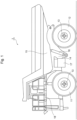
- the unmanned dump truck 1 includes a pair of right and left front wheels 11, a pair of right and left rear wheels 12, wheel shafts 13 coupling the right and left wheels (that is, the front wheels 11 or the rear wheels 12), and a vehicle body 14 as a sturdy frame coupled to the wheel shafts 13 by springs or the like.
- a loading platform 15 for loading the earth, sand, and the like is mounted on the vehicle body 14, and the vehicle body 14 is coupled to the loading platform 15 by a hoist cylinder 16.
- a fuel tank 17 is attached to the vehicle body 14.
- the rear wheels 12 are, for example, drive wheels, and connected to a drive motor (not illustrated) or the like.
- a deck 18 on which an operator, a checker, and the like are allowed to walk is mounted to the upper side of the vehicle body 14.
- Fig. 2 is a block configuration diagram illustrating an unmanned dump truck according to the first embodiment.
- the unmanned dump truck 1 includes a plurality of Global Navigation Satellite System (GNSS) antennas 20 that receive a radio wave from a positioning satellite, such as a Global Positioning System (GPS), and a GNSS receiver 21 that measures a position (also referred to as a current position) and a speed (hereinafter referred to as a "GNSS speed") of the unmanned dump truck 1 based on information received by the GNSS antennas 20.
- GPS Global Positioning System
- GNSS speed a speed of the unmanned dump truck 1 based on information received by the GNSS antennas 20.
- the GNSS receiver 21 outputs the measured position and GNSS speed of the unmanned dump truck 1 to a control device 28 (described later).
- An acceleration sensor 22, a wheel speed sensor 23, a steering angle sensor 24, a load sensor 25, a driving torque sensor 26, a vehicle body posture sensor 27, and the control device 28 are each attached to the vehicle body 14 of the unmanned dump truck 1.
- the acceleration sensor 22 measures an acceleration including a gravity direction applied to the unmanned dump truck 1 in a vehicle body coordinate system b (that is, a coordinate system fixed to the vehicle body 14), and outputs the measurement result to the control device 28.
- the wheel speed sensor 23 measures a wheel speed based on a rotation speed of the wheels (here, the rear wheels 12 as drive wheels), and outputs the measurement result to the control device 28.
- the steering angle sensor 24 measures a steering direction of the unmanned dump truck 1.
- the steering angle sensor 24 measures the steering direction of the front wheels 11 as driven wheels, and outputs the measurement result to the control device 28.
- the load sensor 25 measures a vehicle weight of the unmanned dump truck 1 including a load weight, and outputs it to the control device 28.
- the load sensor 25 measures the load weight of the loading platform 15, and outputs a summed value of the measured load weight and a stored unladen vehicle weight to the control device 28 as the vehicle weight.
- the driving torque sensor 26 measures a driving torque output by the drive wheels (that is, the rear wheels 12), and outputs the measurement result to the control device 28.
- the vehicle body posture sensor 27 measures a vehicle body posture of the unmanned dump truck 1.
- the vehicle body posture sensor 27 measures a vehicle body posture represented by an inclination angle that is formed by a horizontal plane constituted by an Xe axis and a Ye axis of a global coordinate system e (that is, a coordinate system fixed to the earth) and an Xb axis and a Yb axis of the vehicle body coordinate system b and by a rotation angle from the Xe axis of the global coordinate system e to the Xb axis of the vehicle body coordinate system b, and the vehicle body posture sensor 27 outputs the measurement result to the control device 28.
- the control device 28 controls the entire vehicle of the unmanned dump truck 1.
- the control device 28 is configured by, for example, a microcomputer including a combination of a Central Processing Unit (CPU) that executes calculations, a Read Only Memory (ROM) as a secondary storage unit that stores programs for calculations, and a Random Access Memory (RAM) as a temporary storage unit that stores a calculation progress and a temporary control variable, and the control device 28 performs respective controls on the travel, the operation, and the like of the unmanned dump truck 1 by executing the stored programs.
- CPU Central Processing Unit
- ROM Read Only Memory
- RAM Random Access Memory
- the inventor seriously studied focusing on a road gradient and wheel sinking caused by the soft dirt having a large influence on the driving torque of the unmanned dump truck 1.
- the vehicle body posture sensor 27 since the vehicle body posture sensor 27 is attached to the vehicle body 14, the measurement result by the vehicle body posture sensor 27 is different from a road gradient of the route on which the unmanned dump truck 1 actually traveled. Therefore, the inventors decided to measure each of a distance that the unmanned dump truck 1 traveled in the horizontal direction (hereinafter referred to as a horizontal advance distance) and a travel distance that the unmanned dump truck 1 traveled along the road surface in the horizontal advance distance, and obtain the road gradient from the relation between the horizontal advance distance and the travel distance using the trigonometric function.
- a horizontal advance distance a distance that the unmanned dump truck 1 traveled in the horizontal direction
- the slip rate is obtained by calculating an inertia speed vector from the GNSS speed measured by the GNSS receiver 21 and the acceleration measured by the acceleration sensor 22 and calculating a wheel speed vector from the wheel speed measured by the wheel speed sensor 23 and the driven wheel direction measured by the steering angle sensor 24, and calculating a difference between the calculated inertia speed vector and wheel speed vector.
- a traction coefficient for obtaining a traction that varies depending on the state of the road surface is calculated using the acceleration measured by the acceleration sensor 22, the vehicle weight measured by the load sensor 25, and the driving torque measured by the driving torque sensor 26 in addition to the obtained slip rate.
- a target torque that is, required driving torque
- the driving torque of the unmanned dump truck 1 is controlled toward the calculated target torque. Accordingly, the speed of the unmanned dump truck 1 can be controlled to cause the unmanned dump truck 1 to travel to a destination with high accuracy.
- the control device 28 of the embodiment includes a gradient change point calculator 29, an inertia speed vector calculator 30, a road gradient calculator 31, a wheel speed vector calculator 32, a slip rate calculator 33, a traction coefficient calculator 34, a target torque calculator 35, a target acceleration calculator 36, a driving torque controller 37, a route setting controller 38, and a storage unit 39.
- the gradient change point calculator 29 calculates a gradient change point of the road surface based on a pitch angle measured by the vehicle body posture sensor 27 and the position measured by the GNSS receiver 21.
- the gradient change point calculator 29 outputs the calculation result to the road gradient calculator 31.
- the inertia speed vector calculator 30 calculates an inertia speed vector as a speed of the unmanned dump truck 1 based on the GNSS speed measured by the GNSS receiver 21 and the acceleration measured by the acceleration sensor 22.
- the inertia speed vector calculator 30 outputs the calculation result to the road gradient calculator 31.
- the road gradient calculator 31 calculates a road gradient based on the current position measured by the GNSS receiver 21, the gradient change point calculated by the gradient change point calculator 29, and the inertia speed vector calculated by the inertia speed vector calculator 30.
- the road gradient calculator 31 outputs the calculation result to the target torque calculator 35.
- the wheel speed vector calculator 32 calculates a wheel speed vector based on the wheel speed measured by the wheel speed sensor 23 and the driven wheel direction measured by the steering angle sensor 24.
- the wheel speed vector calculator 32 outputs the calculation result to the slip rate calculator 33.
- the slip rate calculator 33 calculates a slip rate of the road surface based on the inertia speed vector calculated by the inertia speed vector calculator 30 and the wheel speed vector calculated by the wheel speed vector calculator 32.
- the slip rate calculator 33 outputs the calculation result to the traction coefficient calculator 34.
- the traction coefficient calculator 34 calculates a traction coefficient corresponding to the road gradient and the soft degree (softness of dirt, in other words) based on the slip rate calculated by the slip rate calculator 33, the vehicle weight output from the load sensor 25, the driving torque measured by the driving torque sensor 26, and the acceleration measured by the acceleration sensor 22.
- the traction coefficient calculator 34 outputs the calculation result to the target torque calculator 35.
- the target acceleration calculator 36 calculates a target acceleration as a required acceleration of the unmanned dump truck 1 based on the current position measured by the GNSS receiver 21 and the route set by the route setting controller 38.
- the target acceleration calculator 36 outputs the calculation result to the target torque calculator 35.
- the target torque calculator 35 calculates a target torque based on the road gradient calculated by the road gradient calculator 31, the traction coefficient calculated by the traction coefficient calculator 34, and the target acceleration calculated by the target acceleration calculator 36.
- the target torque means a driving torque for generating the target acceleration to change the vehicle speed to a target speed.
- the target torque calculator 35 outputs the calculation result to the driving torque controller 37.
- the driving torque controller 37 controls the driving torque of the drive wheels based on the target torque calculated by the target torque calculator 35, thereby controlling the speed of the unmanned dump truck 1.
- the driving torque controller 37 controls the driving torque of the drive wheels to be the target torque.
- the route setting controller 38 sets the route to a stop position as a destination (for example, a stop position of the hydraulic excavator or a dumping site) of the unmanned dump truck 1.
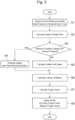
- Fig. 3 is a drawing illustrating a processing flow of a control device
- Fig. 4 to Fig. 11 illustrate the detailed explanations of the processing flow illustrated in Fig. 3 .
- the process illustrated in Fig. 3 is performed on the premise that the route to the stop position as the destination of the unmanned dump truck 1 is preliminarily set by the route setting controller 38, and the gradient on the route is unknown. It is assumed that the process illustrated in Fig. 3 is started in the same cycle (for example, every 0.01 seconds) and the whole process ends within the cycle.
- Step S1 the control device 28 acquires the current position of the unmanned dump truck 1 from the GNSS receiver 21 and the vehicle body posture from the vehicle body posture sensor 27, and causes the storage unit 39 to store the acquired result.
- Step S2 subsequent to Step S1, the gradient change point calculator 29 calculates the gradient change point of the road surface.
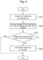
- the gradient change point is a point indicating that the gradient of the road surface on which the unmanned dump truck 1 travels has changed by a certain degree or more, and calculated by, for example, the process of Fig. 4 .
- the gradient change point calculator 29 acquires a pitch angle series from the storage unit 39.
- a gradient change table as illustrated in Fig. 5 is stored.
- the gradient change table includes the pitch angle, a long-term window average and a short-term window average of the gradient change, a gradient change flag, the travel distance, and the gradient for each position of the unmanned dump truck 1.
- Initial values of the gradient change table are all "0 (zero)."
- Step S22 the gradient change point calculator 29 converts the pitch angles into a series relative to the position, and calculates each of the average in long-term window and the average in short-term window.
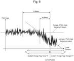
- Fig. 6 is a drawing illustrating a conceptual diagram of calculating an average of a pitch angle series.
- the long-term window is a pitch angle series from a position apart from the current position of the unmanned dump truck 1 by N meters
- the short-term window is a pitch angle series from a position apart from the current position by n meters.
- the gradient change point calculator 29 calculates these averages, and causes the storage unit 39 to store the calculation result.
- the long-term window is set to 10 meters
- the short-term window is set to 3 meters.
- Step S23 subsequent to Step S22, first, the gradient change point calculator 29 calculates a difference between the average in the long-term window and the average in the short-term window.
- the control device 28 determines whether the calculated difference in average is equal to or more than a preliminarily set first threshold or not.
- the first threshold here is set based on, for example, an empirical value, and changeable depending on the object.
- Step S24 since the presence of the gradient change is detected, the gradient change point calculator 29 sets the gradient change flag to "1" and causes the storage unit 39 to store it. Meanwhile, when it is determined that the difference in average is smaller than the first threshold, since the gradient change point is not present, the gradient change point calculator 29 sets the gradient change flag to "0 (zero)" and causes the storage unit 39 to store it. Thus, the calculation process of the gradient change point ends.
- Step S3 when the calculation of the gradient change point ends, the process transitions to Step S3.
- the road gradient calculator 31 calculates a distance from the current position of the unmanned dump truck 1 to the gradient change point calculated in Step S2.
- the control device 28 determines whether the calculated distance is greater than a preliminarily set second threshold or not.
- the second threshold here is set in consideration of an integration error of the speed calculated in Step S5 below and a height error of a three-dimensional position, and set to, for example, the same value as the above-described long-term window.
- the second threshold may be set to an appropriate value depending on the object.
- Step S4 the road gradient calculator 31 calculates the gradient based on the three-dimensional position.
- the calculation of a gradient S based on the three-dimensional position is performed based on a position (xA, yA, zA) of the gradient change flag "1" that is the closest to the current position indicated in the gradient change table of Fig. 5 and the current position (xc, yc, zc) using Formula (1) below.
- [Math. 1] S tan ⁇ 1 zc ⁇ zA xc ⁇ xA 2 + yc ⁇ yA 2
- Step S5 the road gradient calculator 31 calculates the gradient based on the speed.
- the calculation of the gradient based on the speed is performed by, for example, the process of Fig. 7 .
- the inertia speed vector calculator 30 calculates the inertia speed of the unmanned dump truck 1 based on the GNSS speed measured by the GNSS receiver 21 and the acceleration measured by the acceleration sensor 22.
- the inertia speed is represented by the inertia speed vector.
- the inertia speed vector is calculated according to the process of Fig. 8 .
- a speed direction of the unmanned dump truck 1 is output in the global coordinate system at regular intervals.
- the output cycle of the GNSS speed is longer than the output cycle of the acceleration sensor 22, and the output cycle of the acceleration sensor 22 is the same as the output cycle of the control device 28.
- Step S511 the inertia speed vector calculator 30 acquires a speed vector at a previous sample time stored in the storage unit 39.
- Step S512 subsequent to Step S511 the inertia speed vector calculator 30 acquires the acceleration vector from the acceleration sensor 22.
- Step S513 the control device 28 determines whether or not to be in an acquisition cycle of the GNSS speed.
- the process transitions to Step S514.
- the inertia speed vector calculator 30 converts the GNSS speed vector into the vehicle body coordinate system, and sets it as an inertia speed vector v;.
- V is the GNSS speed
- C eb is a coordinate transformation matrix from the vehicle body coordinate system b to the global coordinate system e .
- the coordinate transformation matrix C eb is obtained from a roll angle ⁇ , a pitch angle ⁇ , and a yaw angle ⁇ obtained from the vehicle body posture sensor 27 using Formula (3) below.
- Step S513 when it is determined not to be in the acquisition cycle of the GNSS speed in Step S513, the control process transitions to Step S515, and the inertia speed vector calculator 30 calculates the speed by integrating the acceleration.
- Step S515 the inertia speed vector calculator 30 calculates an unacquired period of the GNSS speed (GNSS speed unacquired period) by calculating a difference between the time of the final acquisition of the GNSS speed and the current time.
- Step S516 subsequent to Step S515 the control device 28 determines whether the GNSS speed unacquired period calculated in Step S515 is smaller than a preliminarily set third threshold or not. This is because, since the speed calculated by integrating the acceleration causes an error due to the integrated time, the error can be suppressed by setting the upper limit of the error due to the time.
- the third threshold is set, for example, in consideration of a time period keeping a speed design target value.
- Step S517 the inertia speed vector calculator 30 sets an inertia speed calculation flag to "0 (impossible to calculate)." Meanwhile, when the GNSS speed unacquired period is determined to be smaller than the third threshold, the process transitions to Step S518, and the inertia speed vector is calculated. In Step S518, the inertia speed vector calculator 30 calculates the speed at the current time by adding the acceleration vector acquired in Step S512 to the speed vector at the previous sample time acquired in Step S511.
- a speed v i (t) at the current time using an acceleration a is calculated based on Formula (4) below with a unit period dt.
- vi(t-1) is a speed at the previous sample time.
- Step S519 subsequent to Step S518, the inertia speed vector calculator 30 sets the inertia speed calculation flag to "1 (possible to calculate)." Thus, the calculation process of the inertia speed vector ends.
- Step S52 the road gradient calculator 31 calculates a travel distance (that is, a travel distance at the current time) that the unmanned dump truck 1 has traveled along the road surface by integrating the inertia speed after the gradient change point.
- the travel distance Lv(t) at the current time is obtained by adding a value obtained by multiplying the inertia speed v(t) calculated in Step S51 by the sample period dt to the previous travel distance Lv(t-1) stored in the storage unit 39 as indicated by Formula (5) below.
- Lv t Lv t ⁇ 1 + v t dt
- Step S51 When the inertia speed calculation flag is "0 (impossible to calculate)" in Step S51, the wheel speed output from the driven wheels (that is, the front wheels 11) may be used as a substitution, or the previous inertia speed may be used as a substitution.
- Step S53 the road gradient calculator 31 calculates the horizontal advance distance of the unmanned dump truck 1.
- Step S54 the control device 28 determines whether the travel distance calculated in Step S52 is equal to or more than a preliminarily set fourth threshold or not.
- the fourth threshold here is set, for example, under a condition that the horizontal advance distance is sufficiently long to the accuracy of the position measured by the GNSS receiver 21.
- Step S55 the road gradient calculator 31 sets the previous gradient S(t-1) directly as the current gradient S(t), and causes the storage unit 39 to store the set result. Meanwhile, when the travel distance is determined to be equal to or more than the fourth threshold, the process transitions to Step S56.
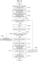
- the traction coefficient is a coefficient for determining the traction caused by the wheels buried in the dirt due to the softness of the road surface (that is, softness of dirt), and stored in a form of a table of Fig. 9 in the storage unit 39.
- the wheels sink.
- the force necessary for traveling is, different from the traction on the paved road, equal to a shear stress of the dirt.
- the shear stress of the dirt has a relation with the slip rate of the drive wheels.
- M is a vehicle weight
- ⁇ is an acceleration of the unmanned dump truck 1
- F is an ideal traction output by the driving torque
- ⁇ is a slip rate
- G ⁇ is a travel resistance caused by the gradient S, and obtained by Formula (9) below.
- the traction F is a driving torque.
- the force generated by the shear force caused by the wheel slip is obtained by multiplying the driving torque F by (C 0 +C 1 ⁇ +C 2 ⁇ 2 +).
- a coefficient C n of a multiplier of each slip rate is referred to as a traction coefficient. Therefore, when the values of the vehicle weight, the acceleration, the driving torque, the slip rate, and the gradient can be measured or calculated multiple times, the traction coefficient can be determined by the least-square method or the like.
- the acceleration can be acquired from the acceleration sensor 22, the vehicle weight can be acquired from the load sensor 25, and the driving torque can be acquired from the driving torque sensor 26.
- the gradient can be calculated in the above-described Step S4 or Step S5. Therefore, when the slip rate is calculated, the traction coefficient can be calculated.
- the wheel speed v w is measured based on the rotation speed of the drive wheels by the wheel speed sensor 23, and the vehicle body advance speed v ix can be calculated by the method similar to the above-described Step S51 (calculation method of the inertia speed).
- the slip rate ⁇ calculated as described above, the acquired vehicle weight, acceleration, and driving torque, and the calculated gradient are stored in the traction coefficient table illustrated in Fig. 9 for each position (that is, current position).
- the traction coefficient calculator 34 updates the traction coefficient C n .
- the traction coefficient C n is prepared by the preliminarily determined number of orders of ⁇ , and the traction coefficients C n of up to the previous value equal to or more than the number of the variables are used. For example, in a case where the traction coefficients are from C 0 to C 1 , when the respective variables at the current position are (Mm, Fm, Sm, ⁇ m), the traction coefficient can be calculated by making two equations of Formula (8) using (M(m-1), F(m-1), S(m-1), ⁇ (m-1)). When the variables are used by the number equal to or more than the number of the traction coefficients, the use of the least-square method or the like allows calculating it.
- the traction coefficient calculated as described above is stored in the storage unit 39.
- Step S7 subsequent to Step S6, the target torque calculator 35 calculates the target torque for outputting a target speed.
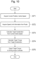
- the target torque is calculated according to the process of Fig. 10 .
- Step S71 the target acceleration calculator 36 acquires each of the current position measured by the GNSS receiver 21 and the inertia speed calculated in Step S51.
- Step S72 subsequent to Step S71, the target acceleration calculator 36 acquires the route to the destination from the route setting controller 38, and further acquires speed limit information set to the route.
- the route is configured by nodes indicating positions of waypoints on the way and a link connecting the nodes.
- the link includes the speed limit in traveling on the link as information.
- the nodes include a last node as the destination, and the unmanned dump truck 1 travels with a target of the speed zero at the last node.
- Step S73 the target acceleration calculator 36 sets a maximum speed profile from the current inertia speed of the unmanned dump truck 1 and a positional relation with the node as a speed change point, and calculates the target acceleration.
- Fig. 11 illustrates an example of the speed profile in the case of traveling from the current position to the destination while decreasing the speed.
- a node (waypoint) 103 is present between a current position 101 and a destination 102.
- the speed profiles at the respective positions are illustrated as a graph in the upper side.
- one-dot chain lines indicate the speed limits set to the link.
- the speed limit is divided into a speed limit 104 between the current position 101 and the waypoint 103 and a speed limit 105 between the waypoint 103 and the destination 102.
- three speed profiles are considered.
- the first one is a speed profile in which the speed is decreased from a speed 109 at the current position 101 to the speed limit 105 at the waypoint 103, and then, further decreased to the destination 102 as illustrated by a dotted line 106.
- the second one is a speed profile in which the speed is constantly decreased from the current position 101 to the destination 102 as illustrated by a dashed line 107.
- the third one is a speed profile in which the speed is once increased to the speed limit 104, 105 for traveling at the maximum speed, and the speed is changed to drive at the speed limit of each node as illustrated by a two-dot chain line 108.
- the setting of the speed profile is selected based on various factors such as a given period for arriving at the destination, priority in travel, and the like.
- a description will be given using the speed profile of the constant deceleration illustrated by the dashed line 107.
- the target acceleration calculator 36 calculates the target acceleration based on the set speed profile.
- a target acceleration a v 2 2 L
- Step S74 the target torque calculator 35 calculates the target torque.
- the target torque is calculated by a back calculation of the driving torque from the above-described Formula (8) using the slip rate, the gradient, the vehicle weight, and the traction coefficient for each position illustrated in Fig. 9 calculated in the above-described Step S6 and stored in the storage unit 39.
- Step S75 the target torque calculator 35 outputs the calculated target torque to the driving torque controller 37.
- Step S8 subsequent to Step S7, the driving torque controller 37 controls the driving torque of the unmanned dump truck 1 to be the target torque, thereby performing a speed control of the unmanned dump truck 1.
- the driving torque controller 37 controls the driving torque of the unmanned dump truck 1 to be the target torque, thereby performing a speed control of the unmanned dump truck 1.
- the unmanned dump truck can travel with high accuracy even on the road surface of the soft dirt.
- the travel control of the unmanned dump truck 1 can be performed with high accuracy.
- the present invention is applied to an example of a plurality of unmanned dump trucks 1. That is, in the case of a plurality of unmanned dump trucks 1, sharing the road gradients, the traction coefficients, and the like calculated by the respective unmanned dump trucks 1 enables the efficient travel of these unmanned dump trucks 1, thus allowing the improvement of the operation efficiency. For example, like the approach to the hydraulic excavator in the drop cut method, since the road gradient, the traction coefficient, and the like significantly change when a route is additionally generated, sharing the road gradients, the traction coefficients, and the like calculated by the respective unmanned dump trucks 1 allows improving the efficiency of the drop cut method.
- the road gradients and the traction coefficients calculated by the respective unmanned dump trucks 1 are regularly transmitted to a control system 2, and managed in the control system 2 side.
- Fig. 12 is a block diagram illustrating a schematic configuration of an unmanned dump truck, a control system, and a hydraulic excavator according to a second embodiment.
- a plurality of the unmanned dump trucks 1, the control system 2, and a hydraulic excavator 3 constitute, for example, a mining machine management system.
- Each of the unmanned dump trucks I is configured to communicate with the control system 2 and the hydraulic excavator 3 via a communication unit 19 provided to each unmanned dump truck 1.
- a plurality of the unmanned dump trucks 1 each regularly transmit the calculated road gradient and traction coefficient together with the travel route to the control system 2 via the communication unit 19 in the unmanned dump truck 1 side and a communication unit 2b in the control system 2 side.
- the control system 2 stores and accumulates the travel routes and corresponding road gradients and traction coefficients transmitted from the respective unmanned dump trucks 1 in a map database 2a.
- the control device 28 of the unmanned dump truck 1 requires the control system 2 to provide information regarding the route on which the unmanned dump truck 1 is to travel, and when the route is stored in the map database 2a of the control system 2, the control device 28 receives the route and uses it for calculating the driving torque necessary for the travel of its own vehicle.
- the control device 28 calculates the driving torque similarly to the first embodiment. The following describes the process in detail with reference to Fig. 13 .
- Step S101 the control device 28 receives an instruction on the stop position and the stop orientation from a stop position instruction unit 3a of the hydraulic excavator 3 via the communication unit 19 in the unmanned dump truck 1 side and a communication unit 3b in the hydraulic excavator 3 side, and outputs the received stop position and stop orientation to the route setting controller 38.
- Step S102 subsequent to Step S101 the control device 28 transmits the information on the stop position to the control system 2 via the communication unit 19 in the unmanned dump truck 1 side and the communication unit 2b in the control system 2 side.
- the control system 2 reads information on the route to the stop position from the map database 2a based on the received stop position information, and transmits the route information to the control device 28 of the unmanned dump truck 1.
- the road gradient and the traction coefficient corresponding to the route are transmitted together.
- the control device 28 outputs the received result to the route setting controller 38.
- the control system 2 transmits an impossible value such as "null” indicating a non-existent route to the control device 28.
- the control system 2 transmits the route present in the map database 2a, and also transmits an impossible value such as "null” indicating a non-existent route.
- Step S103 subsequent to Step S102 similarly to Step S1 described in the first embodiment, the current position and the vehicle body posture of the unmanned dump truck 1 are acquired.
- Step S104 the control device 28 determines whether the route information received in Step S102 includes the impossible value or not.
- the route information is determined not to include the impossible value (in other words, when the route information includes the entire route to the stop position), since the road gradient and the traction coefficient corresponding to the route are acquired, the process transitions to Step S105.
- Step S105 the target torque is calculated by the method similar to that of the above-described Step S7. At this time, the target torque is calculated using the road gradient and the traction coefficient acquired from the control system 2. After the target torque is calculated, the process transitions to Step S114.
- Step S106 since this unmanned dump truck 1 generates the route at first, the route is newly set by the route setting controller 38. At this time, for example, as illustrated in Fig. 14 , the route setting controller 38 draws a straight line passing through a stop position 201 as the destination in a stop instruction orientation 202 of the unmanned dump truck 1 at first, and obtains an intersection point 204 with a route 203 acquired from the control system 2.
- the route setting controller 38 sets the travel route to the intersection point 204 by including a switchback or the like so as to make the unmanned dump truck 1 in the orientation. Note that the travel from the stop position 201 to the intersection point 204 is assumed to be only straight ahead.
- the setting of the route illustrated in Fig. 14 is merely an example, the route may be set by other methods, and the same effects are provided.
- Steps S107 to S111 subsequent to Step S106 are similar to Steps S2 to S6 described in the first embodiment, the repeated explanations will be omitted.
- the wheel speed of the driven wheels can be used as a substitution. That is, in the case of traveling straight ahead, the travel distance along the road surface may be calculated from the wheel speed of the front wheels 11 as the driven wheels.
- Step S112 subsequent to Step S111 the road gradient calculated in Step S109 or Step S110 and the traction coefficient calculated in Step S111 are transmitted to the control system 2 together with the current position.
- the control system 2 receives the information, and stores the information in the map database 2a or updates the map database 2a.
- Step S113 subsequent to Step S112, the target torque is calculated by the method similar to that of Step S7 described in the first embodiment.
- Step S114 the driving torque of the unmanned dump truck 1 is controlled based on the target torque calculated in Step S105 or Step S113.
- the operational advantage similar to that of the first embodiment can be obtained. Additionally, since the route can be generated in a short time by sharing the road gradients and the traction coefficients calculated by a plurality of the unmanned dump trucks 1, a plurality of the unmanned dump trucks 1 can be efficiently traveled, thus allowing the improvement of the operation efficiency.
- the present invention is not limited to the above-described embodiments, but various kinds of changes of design are allowed within a range not departing from the spirits of the present invention described in the claims.
- the present invention is applied to a modification in which a part of the first embodiment and a part of the second embodiment are mutually interchanged or mutually combined. In this case, the effect similar to that of the first embodiment or the second embodiment is obtained.
Landscapes
- Engineering & Computer Science (AREA)
- Automation & Control Theory (AREA)
- Transportation (AREA)
- Mechanical Engineering (AREA)
- Physics & Mathematics (AREA)
- Mathematical Physics (AREA)
- Control Of Position, Course, Altitude, Or Attitude Of Moving Bodies (AREA)
- Control Of Driving Devices And Active Controlling Of Vehicle (AREA)
Abstract
Description
- The present invention relates to a mining machine that travels in a mine.
- This application claims priority to
Japanese Patent Application No. 2020-161342 filed on September 25, 2020 - For example, in a mine where surface mining is performed, a method referred to as drop cut in which a hydraulic excavator digs a level ground and a dump truck carries out dirt or the like discharged there is employed. In this method, the hydraulic excavator digs a flat place, an inclined path is gradually generated, the dump truck travels down on the generated inclined path, and the dump truck carries out the dirt or the like dug out by the hydraulic excavator to a dumping site. Therefore, not only a loading work to the dump truck by the hydraulic excavator but also a conveyance work by the dump truck is performed not on a flat place but in a state where the dump truck is heavily inclined.
- Nowadays, a technique of introducing an unmanned dump truck into the above-described method for improving the safety and the productivity of the mine site and saving the labor costs. However, when the mining place is expanded, since map data is not prepared in advance, and the unmanned dump truck travels on a road surface with a large gradient, a control to move or stop the unmanned dump truck to a designated position of the hydraulic excavator is performed based on only an estimated position and a posture. For a travel path whose road gradient is not acquired in advance, examples of a method for calculating a road gradient and traveling on the travel path includes, as disclosed in
Patent Literature 1, a method in which a road gradient is calculated based on a height difference between adjacent points acquired from a measurement or a travel result of a truck to set a target travel speed. - Patent Literature 1:
JP 2019-133473 A - However, on a newly generated road surface, a road surface containing a large amount of water, or the like, wheels often sink due to the soft dirt. Accordingly, since the traveling is performed against the travel resistance due to the wheel sinking in addition to the road gradient, it becomes difficult to calculate the driving torque, and therefore, it has been difficult to accurately control traveling to a point as a destination.
- The present invention has been made to solve the technical problem, and it is an object to provide a mining machine configured to calculate a driving torque in consideration of a road gradient and wheel sinking and perform a travel control with high accuracy.
- A mining machine according to the present invention is a mining machine comprising: a GNSS receiver that measures a position and a speed of the mining machine traveling in a mine based on a radio wave received from a positioning satellite; a vehicle body posture sensor that measures a vehicle body posture of the mining machine; an acceleration sensor that measures an acceleration of the mining machine; a wheel speed sensor that measures a wheel speed based on a wheel rotation speed of the mining machine; a steering angle sensor that measures a steering direction of the mining machine; a load sensor that measures a vehicle weight of the mining machine including a load weight; a driving torque sensor that measures a driving torque of drive wheels of the mining machine; and a control device that controls the mining machine. The control device calculates: a road gradient of a travel route based on the position and the speed measured by the GNSS receiver, the vehicle body posture measured by the vehicle body posture sensor, and the acceleration measured by the acceleration sensor; calculates a traction coefficient based on the speed measured by the GNSS receiver, the acceleration measured by the acceleration sensor, the wheel speed measured by the wheel speed sensor, the steering direction measured by the steering angle sensor, the vehicle weight measured by the load sensor, and the driving torque measured by the driving torque sensor; calculates a target torque of the mining machine based on the calculated road gradient and the calculated traction coefficient; and controls the driving torque of the drive wheels to be the calculated target torque.
- In the mining machine according to the present invention, the control device calculates a road gradient of a travel route based on the position and the speed measured by the GNSS receiver, the vehicle body posture measured by the vehicle body posture sensor, and the acceleration measured by the acceleration sensor, and calculates a traction coefficient based on the speed measured by the GNSS receiver, the acceleration measured by the acceleration sensor, the wheel speed measured by the wheel speed sensor, the steering direction measured by the steering angle sensor, the vehicle weight measured by the load sensor, and the driving torque measured by the driving torque sensor. Further, the control device calculates a target torque of the mining machine based on the calculated road gradient and the calculated traction coefficient. Thus, by calculating the driving torque in consideration of the road gradient of the travel route and the wheel sinking, the travel control of the mining machine can be performed with high accuracy.
- According to the present invention, by calculating the driving torque in consideration of the road gradient and the wheel sinking, the travel control of the mining machine can be performed with high accuracy.
-
-
Fig. 1 is a side view of illustrating a schematic configuration of an unmanned dump truck. -
Fig. 2 is a block configuration diagram illustrating an unmanned dump truck according to a first embodiment. -
Fig. 3 is a drawing illustrating a processing flow of a control device. -
Fig. 4 is a drawing illustrating a processing flow of a gradient change point calculation. -
Fig. 5 is a drawing illustrating a gradient change table stored in a storage unit. -
Fig. 6 is a drawing illustrating a conceptual diagram of calculating an average of a pitch angle series. -
Fig. 7 is a drawing illustrating a processing flow of a gradient calculation based on a speed. -
Fig. 8 is a drawing illustrating a processing flow of an inertia speed vector calculation. -
Fig. 9 is a drawing illustrating a traction coefficient table stored in the storage unit. -
Fig. 10 is a drawing illustrating a processing flow of a target torque calculation. -
Fig. 11 is a drawing illustrating a concept of setting a speed profile. -
Fig. 12 is a block diagram illustrating a schematic configuration of an unmanned dump truck, a control system, and a hydraulic excavator according to a second embodiment. -
Fig. 13 is a drawing illustrating a processing flow of the second embodiment. -
Fig. 14 is a drawing illustrating an exemplary route setting of the second embodiment. - The following describes embodiments of a mining machine according to the present invention with reference to the drawings. In the descriptions of the drawings, the same reference numerals are attached to the same components, and the repeated explanations will be omitted. While an unmanned dump truck is described as an example of the mining machine in the following description, the present invention is not limited to the unmanned dump truck.
- An unmanned dump truck I is an autonomously drivable vehicle in a mine where surface mining is performed. As illustrated in
Fig. 1 , theunmanned dump truck 1 includes a pair of right and leftfront wheels 11, a pair of right and leftrear wheels 12,wheel shafts 13 coupling the right and left wheels (that is, thefront wheels 11 or the rear wheels 12), and avehicle body 14 as a sturdy frame coupled to thewheel shafts 13 by springs or the like. Aloading platform 15 for loading the earth, sand, and the like is mounted on thevehicle body 14, and thevehicle body 14 is coupled to theloading platform 15 by ahoist cylinder 16. Afuel tank 17 is attached to thevehicle body 14. Therear wheels 12 are, for example, drive wheels, and connected to a drive motor (not illustrated) or the like. Adeck 18 on which an operator, a checker, and the like are allowed to walk is mounted to the upper side of thevehicle body 14. -
Fig. 2 is a block configuration diagram illustrating an unmanned dump truck according to the first embodiment. Theunmanned dump truck 1 includes a plurality of Global Navigation Satellite System (GNSS)antennas 20 that receive a radio wave from a positioning satellite, such as a Global Positioning System (GPS), and a GNSSreceiver 21 that measures a position (also referred to as a current position) and a speed (hereinafter referred to as a "GNSS speed") of theunmanned dump truck 1 based on information received by the GNSSantennas 20. The GNSSreceiver 21 outputs the measured position and GNSS speed of theunmanned dump truck 1 to a control device 28 (described later). - An
acceleration sensor 22, awheel speed sensor 23, asteering angle sensor 24, aload sensor 25, adriving torque sensor 26, a vehiclebody posture sensor 27, and thecontrol device 28 are each attached to thevehicle body 14 of theunmanned dump truck 1. - The
acceleration sensor 22 measures an acceleration including a gravity direction applied to theunmanned dump truck 1 in a vehicle body coordinate system b (that is, a coordinate system fixed to the vehicle body 14), and outputs the measurement result to thecontrol device 28. Thewheel speed sensor 23 measures a wheel speed based on a rotation speed of the wheels (here, therear wheels 12 as drive wheels), and outputs the measurement result to thecontrol device 28. - The
steering angle sensor 24 measures a steering direction of theunmanned dump truck 1. In this embodiment, thesteering angle sensor 24 measures the steering direction of thefront wheels 11 as driven wheels, and outputs the measurement result to thecontrol device 28. Theload sensor 25 measures a vehicle weight of theunmanned dump truck 1 including a load weight, and outputs it to thecontrol device 28. For example, theload sensor 25 measures the load weight of theloading platform 15, and outputs a summed value of the measured load weight and a stored unladen vehicle weight to thecontrol device 28 as the vehicle weight. The drivingtorque sensor 26 measures a driving torque output by the drive wheels (that is, the rear wheels 12), and outputs the measurement result to thecontrol device 28. - The vehicle
body posture sensor 27 measures a vehicle body posture of theunmanned dump truck 1. In this embodiment, the vehiclebody posture sensor 27 measures a vehicle body posture represented by an inclination angle that is formed by a horizontal plane constituted by an Xe axis and a Ye axis of a global coordinate system e (that is, a coordinate system fixed to the earth) and an Xb axis and a Yb axis of the vehicle body coordinate system b and by a rotation angle from the Xe axis of the global coordinate system e to the Xb axis of the vehicle body coordinate system b, and the vehiclebody posture sensor 27 outputs the measurement result to thecontrol device 28. - The
control device 28 controls the entire vehicle of theunmanned dump truck 1. Thecontrol device 28 is configured by, for example, a microcomputer including a combination of a Central Processing Unit (CPU) that executes calculations, a Read Only Memory (ROM) as a secondary storage unit that stores programs for calculations, and a Random Access Memory (RAM) as a temporary storage unit that stores a calculation progress and a temporary control variable, and thecontrol device 28 performs respective controls on the travel, the operation, and the like of theunmanned dump truck 1 by executing the stored programs. - Here, a background to the present invention will be described.
- To solve the above-described problem, the inventor seriously studied focusing on a road gradient and wheel sinking caused by the soft dirt having a large influence on the driving torque of the
unmanned dump truck 1. - First, since the vehicle
body posture sensor 27 is attached to thevehicle body 14, the measurement result by the vehiclebody posture sensor 27 is different from a road gradient of the route on which theunmanned dump truck 1 actually traveled. Therefore, the inventors decided to measure each of a distance that theunmanned dump truck 1 traveled in the horizontal direction (hereinafter referred to as a horizontal advance distance) and a travel distance that theunmanned dump truck 1 traveled along the road surface in the horizontal advance distance, and obtain the road gradient from the relation between the horizontal advance distance and the travel distance using the trigonometric function. - Next, regarding the wheel sinking caused by the soft dirt, the inventors decided to use a slip rate as a function of the amount of wheel sinking. The slip rate is obtained by calculating an inertia speed vector from the GNSS speed measured by the
GNSS receiver 21 and the acceleration measured by theacceleration sensor 22 and calculating a wheel speed vector from the wheel speed measured by thewheel speed sensor 23 and the driven wheel direction measured by thesteering angle sensor 24, and calculating a difference between the calculated inertia speed vector and wheel speed vector. - Further, a traction coefficient for obtaining a traction that varies depending on the state of the road surface, such as a gradient and a softness of dirt, is calculated using the acceleration measured by the
acceleration sensor 22, the vehicle weight measured by theload sensor 25, and the driving torque measured by the drivingtorque sensor 26 in addition to the obtained slip rate. Using the traction coefficient, a target torque (that is, required driving torque) for obtaining a target acceleration at each position is calculated from the gradient and the slip rate at each position assuming that the same nature of the dirt continues, and the driving torque of theunmanned dump truck 1 is controlled toward the calculated target torque. Accordingly, the speed of theunmanned dump truck 1 can be controlled to cause theunmanned dump truck 1 to travel to a destination with high accuracy. - Accordingly, to achieve the above description, the
control device 28 of the embodiment includes a gradientchange point calculator 29, an inertiaspeed vector calculator 30, aroad gradient calculator 31, a wheelspeed vector calculator 32, aslip rate calculator 33, atraction coefficient calculator 34, atarget torque calculator 35, atarget acceleration calculator 36, a drivingtorque controller 37, aroute setting controller 38, and astorage unit 39. - The gradient
change point calculator 29 calculates a gradient change point of the road surface based on a pitch angle measured by the vehiclebody posture sensor 27 and the position measured by theGNSS receiver 21. The gradientchange point calculator 29 outputs the calculation result to theroad gradient calculator 31. - The inertia
speed vector calculator 30 calculates an inertia speed vector as a speed of theunmanned dump truck 1 based on the GNSS speed measured by theGNSS receiver 21 and the acceleration measured by theacceleration sensor 22. The inertiaspeed vector calculator 30 outputs the calculation result to theroad gradient calculator 31. - The
road gradient calculator 31 calculates a road gradient based on the current position measured by theGNSS receiver 21, the gradient change point calculated by the gradientchange point calculator 29, and the inertia speed vector calculated by the inertiaspeed vector calculator 30. Theroad gradient calculator 31 outputs the calculation result to thetarget torque calculator 35. - The wheel
speed vector calculator 32 calculates a wheel speed vector based on the wheel speed measured by thewheel speed sensor 23 and the driven wheel direction measured by thesteering angle sensor 24. The wheelspeed vector calculator 32 outputs the calculation result to theslip rate calculator 33. - The
slip rate calculator 33 calculates a slip rate of the road surface based on the inertia speed vector calculated by the inertiaspeed vector calculator 30 and the wheel speed vector calculated by the wheelspeed vector calculator 32. Theslip rate calculator 33 outputs the calculation result to thetraction coefficient calculator 34. - The
traction coefficient calculator 34 calculates a traction coefficient corresponding to the road gradient and the soft degree (softness of dirt, in other words) based on the slip rate calculated by theslip rate calculator 33, the vehicle weight output from theload sensor 25, the driving torque measured by the drivingtorque sensor 26, and the acceleration measured by theacceleration sensor 22. Thetraction coefficient calculator 34 outputs the calculation result to thetarget torque calculator 35. - The
target acceleration calculator 36 calculates a target acceleration as a required acceleration of theunmanned dump truck 1 based on the current position measured by theGNSS receiver 21 and the route set by theroute setting controller 38. Thetarget acceleration calculator 36 outputs the calculation result to thetarget torque calculator 35. - The
target torque calculator 35 calculates a target torque based on the road gradient calculated by theroad gradient calculator 31, the traction coefficient calculated by thetraction coefficient calculator 34, and the target acceleration calculated by thetarget acceleration calculator 36. The target torque means a driving torque for generating the target acceleration to change the vehicle speed to a target speed. Thetarget torque calculator 35 outputs the calculation result to the drivingtorque controller 37. - The driving
torque controller 37 controls the driving torque of the drive wheels based on the target torque calculated by thetarget torque calculator 35, thereby controlling the speed of theunmanned dump truck 1. For example, the drivingtorque controller 37 controls the driving torque of the drive wheels to be the target torque. Theroute setting controller 38 sets the route to a stop position as a destination (for example, a stop position of the hydraulic excavator or a dumping site) of theunmanned dump truck 1. - The following describes the travel control of the
unmanned dump truck 1 performed by thecontrol device 28 by calculating the road gradient and the slip rate to calculate the target torque with reference toFig. 3 to Fig. 11 .Fig. 3 is a drawing illustrating a processing flow of a control device, andFig. 4 to Fig. 11 illustrate the detailed explanations of the processing flow illustrated inFig. 3 . - The process illustrated in
Fig. 3 is performed on the premise that the route to the stop position as the destination of theunmanned dump truck 1 is preliminarily set by theroute setting controller 38, and the gradient on the route is unknown. It is assumed that the process illustrated inFig. 3 is started in the same cycle (for example, every 0.01 seconds) and the whole process ends within the cycle. - First, in Step S1, the
control device 28 acquires the current position of theunmanned dump truck 1 from theGNSS receiver 21 and the vehicle body posture from the vehiclebody posture sensor 27, and causes thestorage unit 39 to store the acquired result. - In Step S2 subsequent to Step S1, the gradient
change point calculator 29 calculates the gradient change point of the road surface. The gradient change point is a point indicating that the gradient of the road surface on which theunmanned dump truck 1 travels has changed by a certain degree or more, and calculated by, for example, the process ofFig. 4 . - As illustrated in
Fig. 4 , in Step S21, the gradientchange point calculator 29 acquires a pitch angle series from thestorage unit 39. In thestorage unit 39, a gradient change table as illustrated inFig. 5 is stored. The gradient change table includes the pitch angle, a long-term window average and a short-term window average of the gradient change, a gradient change flag, the travel distance, and the gradient for each position of theunmanned dump truck 1. Initial values of the gradient change table are all "0 (zero)." - In Step S22 subsequent to Step S21, the gradient
change point calculator 29 converts the pitch angles into a series relative to the position, and calculates each of the average in long-term window and the average in short-term window.Fig. 6 is a drawing illustrating a conceptual diagram of calculating an average of a pitch angle series. As illustrated inFig. 6 , the long-term window is a pitch angle series from a position apart from the current position of theunmanned dump truck 1 by N meters, and the short-term window is a pitch angle series from a position apart from the current position by n meters. The gradientchange point calculator 29 calculates these averages, and causes thestorage unit 39 to store the calculation result. For example, the long-term window is set to 10 meters, and the short-term window is set to 3 meters. - In Step S23 subsequent to Step S22, first, the gradient
change point calculator 29 calculates a difference between the average in the long-term window and the average in the short-term window. Next, thecontrol device 28 determines whether the calculated difference in average is equal to or more than a preliminarily set first threshold or not. The first threshold here is set based on, for example, an empirical value, and changeable depending on the object. - When it is determined that the difference in average is equal to or more than the first threshold, the process transitions to Step S24. In Step S24, since the presence of the gradient change is detected, the gradient
change point calculator 29 sets the gradient change flag to "1" and causes thestorage unit 39 to store it. Meanwhile, when it is determined that the difference in average is smaller than the first threshold, since the gradient change point is not present, the gradientchange point calculator 29 sets the gradient change flag to "0 (zero)" and causes thestorage unit 39 to store it. Thus, the calculation process of the gradient change point ends. - As illustrated in
Fig. 3 , when the calculation of the gradient change point ends, the process transitions to Step S3. In Step S3, first, theroad gradient calculator 31 calculates a distance from the current position of theunmanned dump truck 1 to the gradient change point calculated in Step S2. Next, thecontrol device 28 determines whether the calculated distance is greater than a preliminarily set second threshold or not. The second threshold here is set in consideration of an integration error of the speed calculated in Step S5 below and a height error of a three-dimensional position, and set to, for example, the same value as the above-described long-term window. The second threshold may be set to an appropriate value depending on the object. - When the distance to the gradient change point is determined to be greater than the second threshold, the process transitions to Step S4. In Step S4, the
road gradient calculator 31 calculates the gradient based on the three-dimensional position. The calculation of a gradient S based on the three-dimensional position is performed based on a position (xA, yA, zA) of the gradient change flag "1" that is the closest to the current position indicated in the gradient change table ofFig. 5 and the current position (xc, yc, zc) using Formula (1) below.
[Math. 1]
- Meanwhile, when the distance to the gradient change point is determined to be equal to or less than the second threshold, the process transitions to Step S5. In Step S5, the
road gradient calculator 31 calculates the gradient based on the speed. The calculation of the gradient based on the speed is performed by, for example, the process ofFig. 7 . - As illustrated in
Fig. 7 , in Step S51, the inertiaspeed vector calculator 30 calculates the inertia speed of theunmanned dump truck 1 based on the GNSS speed measured by theGNSS receiver 21 and the acceleration measured by theacceleration sensor 22. In this embodiment, the inertia speed is represented by the inertia speed vector. The inertia speed vector is calculated according to the process ofFig. 8 . - For the GNSS speed measured by the
GNSS receiver 21, a speed direction of theunmanned dump truck 1 is output in the global coordinate system at regular intervals. In this embodiment, the output cycle of the GNSS speed is longer than the output cycle of theacceleration sensor 22, and the output cycle of theacceleration sensor 22 is the same as the output cycle of thecontrol device 28. - As illustrated in
Fig. 8 , in Step S511, the inertiaspeed vector calculator 30 acquires a speed vector at a previous sample time stored in thestorage unit 39. In Step S512 subsequent to Step S511, the inertiaspeed vector calculator 30 acquires the acceleration vector from theacceleration sensor 22. - In Step S513 subsequent to Step S512, the
control device 28 determines whether or not to be in an acquisition cycle of the GNSS speed. When it is determined to be in the acquisition cycle of the GNSS speed, the process transitions to Step S514. In Step S514, the inertiaspeed vector calculator 30 converts the GNSS speed vector into the vehicle body coordinate system, and sets it as an inertia speed vector v;. The inertia speed vector vi is calculated by Formula (2) below.
[Math. 2]
- In Formula (2), V is the GNSS speed, and Ceb is a coordinate transformation matrix from the vehicle body coordinate system b to the global coordinate system e. The coordinate transformation matrix Ceb is obtained from a roll angle Ψ , a pitch angle ϕ, and a yaw angle θ obtained from the vehicle
body posture sensor 27 using Formula (3) below.
[Math. 3]
- Meanwhile, when it is determined not to be in the acquisition cycle of the GNSS speed in Step S513, the control process transitions to Step S515, and the inertia
speed vector calculator 30 calculates the speed by integrating the acceleration. In Step S515, the inertiaspeed vector calculator 30 calculates an unacquired period of the GNSS speed (GNSS speed unacquired period) by calculating a difference between the time of the final acquisition of the GNSS speed and the current time. - In Step S516 subsequent to Step S515, the
control device 28 determines whether the GNSS speed unacquired period calculated in Step S515 is smaller than a preliminarily set third threshold or not. This is because, since the speed calculated by integrating the acceleration causes an error due to the integrated time, the error can be suppressed by setting the upper limit of the error due to the time. The third threshold is set, for example, in consideration of a time period keeping a speed design target value. - When the GNSS speed unacquired period is determined to be equal to or more than the third threshold, the process transitions to Step S517. In Step S517, the inertia
speed vector calculator 30 sets an inertia speed calculation flag to "0 (impossible to calculate)." Meanwhile, when the GNSS speed unacquired period is determined to be smaller than the third threshold, the process transitions to Step S518, and the inertia speed vector is calculated. In Step S518, the inertiaspeed vector calculator 30 calculates the speed at the current time by adding the acceleration vector acquired in Step S512 to the speed vector at the previous sample time acquired in Step S511. A speed vi(t) at the current time using an acceleration a is calculated based on Formula (4) below with a unit period dt. In Formula (4), vi(t-1) is a speed at the previous sample time.
[Math. 4]
- In Step S519 subsequent to Step S518, the inertia
speed vector calculator 30 sets the inertia speed calculation flag to "1 (possible to calculate)." Thus, the calculation process of the inertia speed vector ends. - As illustrated in
Fig. 7 , after ending the calculation of the inertia speed, the process transitions to Step S52. In Step S52, theroad gradient calculator 31 calculates a travel distance (that is, a travel distance at the current time) that theunmanned dump truck 1 has traveled along the road surface by integrating the inertia speed after the gradient change point. The travel distance Lv(t) at the current time is obtained by adding a value obtained by multiplying the inertia speed v(t) calculated in Step S51 by the sample period dt to the previous travel distance Lv(t-1) stored in thestorage unit 39 as indicated by Formula (5) below.
[Math. 5]
- When the inertia speed calculation flag is "0 (impossible to calculate)" in Step S51, the wheel speed output from the driven wheels (that is, the front wheels 11) may be used as a substitution, or the previous inertia speed may be used as a substitution.
- In Step S53 subsequent to Step S52, the
road gradient calculator 31 calculates the horizontal advance distance of theunmanned dump truck 1. The horizontal advance distance Lp is calculated by Formula (6) below using x and y of the position (xA, yA, zA) having the gradient change flag "1" that is the closest to the current position in the gradient change table (seeFig. 5 ) stored in thestorage unit 39 and the current position (xc, yc, zc).
[Math. 6]
- In Step S54 subsequent to Step S53, the
control device 28 determines whether the travel distance calculated in Step S52 is equal to or more than a preliminarily set fourth threshold or not. The fourth threshold here is set, for example, under a condition that the horizontal advance distance is sufficiently long to the accuracy of the position measured by theGNSS receiver 21. - When the travel distance is determined to be smaller than the fourth threshold, the process transitions to Step S55. In Step S55, the
road gradient calculator 31 sets the previous gradient S(t-1) directly as the current gradient S(t), and causes thestorage unit 39 to store the set result. Meanwhile, when the travel distance is determined to be equal to or more than the fourth threshold, the process transitions to Step S56. In Step S56, theroad gradient calculator 31 calculates the gradient S(t) based on Formula (7) below, and causes thestorage unit 39 to store the calculation result.
[Math. 7]
- As illustrated in
Fig. 3 , when the gradient is calculated in Step S4 or S5, the process transitions to Step S6, and the traction coefficient is calculated. The traction coefficient is a coefficient for determining the traction caused by the wheels buried in the dirt due to the softness of the road surface (that is, softness of dirt), and stored in a form of a table ofFig. 9 in thestorage unit 39. When the road surface is soft, the wheels sink. In this case, the force necessary for traveling is, different from the traction on the paved road, equal to a shear stress of the dirt. The shear stress of the dirt has a relation with the slip rate of the drive wheels. The equation of motion of the vehicle body in the case of the wheel sinking can be expressed as Formula (8) below.
[Math. 8]
- In Formula (8), M is a vehicle weight, ύ is an acceleration of the
unmanned dump truck 1, F is an ideal traction output by the driving torque, and λ is a slip rate. Gγ is a travel resistance caused by the gradient S, and obtained by Formula (9) below. Here, the traction F is a driving torque.
[Math. 9]
- The force generated by the shear force caused by the wheel slip is obtained by multiplying the driving torque F by (C0+C1λ+C2λ2+...). Here, a coefficient Cn of a multiplier of each slip rate is referred to as a traction coefficient. Therefore, when the values of the vehicle weight, the acceleration, the driving torque, the slip rate, and the gradient can be measured or calculated multiple times, the traction coefficient can be determined by the least-square method or the like.
- The acceleration can be acquired from the
acceleration sensor 22, the vehicle weight can be acquired from theload sensor 25, and the driving torque can be acquired from the drivingtorque sensor 26. The gradient can be calculated in the above-described Step S4 or Step S5. Therefore, when the slip rate is calculated, the traction coefficient can be calculated. - The slip rate λ can be indicated as a ratio between a wheel speed vw and a vehicle body advance speed vix of the
unmanned dump truck 1 as indicated by Formula (10) below.
[Math. 10]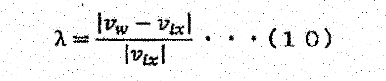
- The wheel speed vw is measured based on the rotation speed of the drive wheels by the
wheel speed sensor 23, and the vehicle body advance speed vix can be calculated by the method similar to the above-described Step S51 (calculation method of the inertia speed). The slip rate λ calculated as described above, the acquired vehicle weight, acceleration, and driving torque, and the calculated gradient are stored in the traction coefficient table illustrated inFig. 9 for each position (that is, current position). - Next, the
traction coefficient calculator 34 updates the traction coefficient Cn. The traction coefficient Cn is prepared by the preliminarily determined number of orders of λ, and the traction coefficients Cn of up to the previous value equal to or more than the number of the variables are used. For example, in a case where the traction coefficients are from C0 to C1, when the respective variables at the current position are (Mm, Fm, Sm, λm), the traction coefficient can be calculated by making two equations of Formula (8) using (M(m-1), F(m-1), S(m-1), λ(m-1)). When the variables are used by the number equal to or more than the number of the traction coefficients, the use of the least-square method or the like allows calculating it. The traction coefficient calculated as described above is stored in thestorage unit 39. - In Step S7 subsequent to Step S6, the
target torque calculator 35 calculates the target torque for outputting a target speed. The target torque is calculated according to the process ofFig. 10 . - As illustrated in
Fig. 10 , in Step S71, thetarget acceleration calculator 36 acquires each of the current position measured by theGNSS receiver 21 and the inertia speed calculated in Step S51. In Step S72 subsequent to Step S71, thetarget acceleration calculator 36 acquires the route to the destination from theroute setting controller 38, and further acquires speed limit information set to the route. The route is configured by nodes indicating positions of waypoints on the way and a link connecting the nodes. The link includes the speed limit in traveling on the link as information. The nodes include a last node as the destination, and theunmanned dump truck 1 travels with a target of the speed zero at the last node. - In Step S73 subsequent to Step S72, the
target acceleration calculator 36 sets a maximum speed profile from the current inertia speed of theunmanned dump truck 1 and a positional relation with the node as a speed change point, and calculates the target acceleration.Fig. 11 illustrates an example of the speed profile in the case of traveling from the current position to the destination while decreasing the speed. As illustrated inFig. 11 , a node (waypoint) 103 is present between acurrent position 101 and adestination 102. The speed profiles at the respective positions are illustrated as a graph in the upper side. - In
Fig. 11 , one-dot chain lines indicate the speed limits set to the link. The speed limit is divided into aspeed limit 104 between thecurrent position 101 and thewaypoint 103 and aspeed limit 105 between thewaypoint 103 and thedestination 102. For example, three speed profiles are considered. The first one is a speed profile in which the speed is decreased from aspeed 109 at thecurrent position 101 to thespeed limit 105 at thewaypoint 103, and then, further decreased to thedestination 102 as illustrated by a dottedline 106. The second one is a speed profile in which the speed is constantly decreased from thecurrent position 101 to thedestination 102 as illustrated by a dashedline 107. The third one is a speed profile in which the speed is once increased to thespeed limit dot chain line 108. - The setting of the speed profile is selected based on various factors such as a given period for arriving at the destination, priority in travel, and the like. In this embodiment, since the following process is not changed even when any speed profile is employed, here, a description will be given using the speed profile of the constant deceleration illustrated by the dashed
line 107. - The
target acceleration calculator 36 calculates the target acceleration based on the set speed profile. When a distance from thecurrent position 101 to thedestination 102 is L, the current inertia speed is v, and theunmanned dump truck 1 stops at the destination, a target acceleration a is obtained by Formula (11) below.
[Math. 11]
- In Step S74 subsequent to Step S73, the
target torque calculator 35 calculates the target torque. The target torque is calculated by a back calculation of the driving torque from the above-described Formula (8) using the slip rate, the gradient, the vehicle weight, and the traction coefficient for each position illustrated inFig. 9 calculated in the above-described Step S6 and stored in thestorage unit 39. In Step S75 subsequent to Step S74, thetarget torque calculator 35 outputs the calculated target torque to the drivingtorque controller 37. - As illustrated in
Fig. 3 , in Step S8 subsequent to Step S7, the drivingtorque controller 37 controls the driving torque of theunmanned dump truck 1 to be the target torque, thereby performing a speed control of theunmanned dump truck 1. Thus, a sequence of the processes ends. - By executing a sequence of the processes from Step S1 to Step S8 for each cycle of the activation of the driving
torque controller 37, the appropriate torque is output during the travel regardless of the change of the road surface state or the gradient, thus enabling the travel with high accuracy. Consequently, the unmanned dump truck can travel with high accuracy even on the road surface of the soft dirt. - According to the
unmanned dump truck 1 configured as described above, since the driving torque is calculated in consideration of the road gradient of the travel route and the wheel sinking, the travel control of theunmanned dump truck 1 can be performed with high accuracy. - While the example assuming that only one unmanned dump truck travels is described in the first embodiment, the present invention is applied to an example of a plurality of
unmanned dump trucks 1. That is, in the case of a plurality ofunmanned dump trucks 1, sharing the road gradients, the traction coefficients, and the like calculated by the respectiveunmanned dump trucks 1 enables the efficient travel of theseunmanned dump trucks 1, thus allowing the improvement of the operation efficiency. For example, like the approach to the hydraulic excavator in the drop cut method, since the road gradient, the traction coefficient, and the like significantly change when a route is additionally generated, sharing the road gradients, the traction coefficients, and the like calculated by the respectiveunmanned dump trucks 1 allows improving the efficiency of the drop cut method. - Therefore, in the second embodiment, the road gradients and the traction coefficients calculated by the respective
unmanned dump trucks 1 are regularly transmitted to acontrol system 2, and managed in thecontrol system 2 side. In the following description, only the difference between the second embodiment and the first embodiment will be described. -
Fig. 12 is a block diagram illustrating a schematic configuration of an unmanned dump truck, a control system, and a hydraulic excavator according to a second embodiment. In the example illustrated inFig. 12 , a plurality of theunmanned dump trucks 1, thecontrol system 2, and ahydraulic excavator 3 constitute, for example, a mining machine management system. Each of the unmanned dump trucks I is configured to communicate with thecontrol system 2 and thehydraulic excavator 3 via acommunication unit 19 provided to eachunmanned dump truck 1. - In this mining machine management system, a plurality of the
unmanned dump trucks 1 each regularly transmit the calculated road gradient and traction coefficient together with the travel route to thecontrol system 2 via thecommunication unit 19 in theunmanned dump truck 1 side and acommunication unit 2b in thecontrol system 2 side. Thecontrol system 2 stores and accumulates the travel routes and corresponding road gradients and traction coefficients transmitted from the respectiveunmanned dump trucks 1 in amap database 2a. - For example, when one
unmanned dump truck 1 travels a route, thecontrol device 28 of theunmanned dump truck 1 requires thecontrol system 2 to provide information regarding the route on which theunmanned dump truck 1 is to travel, and when the route is stored in themap database 2a of thecontrol system 2, thecontrol device 28 receives the route and uses it for calculating the driving torque necessary for the travel of its own vehicle. On the other hand, when the route is not stored in themap database 2a, thecontrol device 28 calculates the driving torque similarly to the first embodiment. The following describes the process in detail with reference toFig. 13 . - First, in Step S101, the
control device 28 receives an instruction on the stop position and the stop orientation from a stop position instruction unit 3a of thehydraulic excavator 3 via thecommunication unit 19 in theunmanned dump truck 1 side and acommunication unit 3b in thehydraulic excavator 3 side, and outputs the received stop position and stop orientation to theroute setting controller 38. - In Step S102 subsequent to Step S101, the
control device 28 transmits the information on the stop position to thecontrol system 2 via thecommunication unit 19 in theunmanned dump truck 1 side and thecommunication unit 2b in thecontrol system 2 side. Thecontrol system 2 reads information on the route to the stop position from themap database 2a based on the received stop position information, and transmits the route information to thecontrol device 28 of theunmanned dump truck 1. When the information on the route to the stop position is transmitted, the road gradient and the traction coefficient corresponding to the route are transmitted together. Thecontrol device 28 outputs the received result to theroute setting controller 38. - When the information on the route to the stop position is not present in the
map database 2a (in other words, a case of not being stored in themap database 2a), thecontrol system 2 transmits an impossible value such as "null" indicating a non-existent route to thecontrol device 28. When only a part of the route to the stop position is present in themap database 2a, thecontrol system 2 transmits the route present in themap database 2a, and also transmits an impossible value such as "null" indicating a non-existent route. - In Step S103 subsequent to Step S102, similarly to Step S1 described in the first embodiment, the current position and the vehicle body posture of the
unmanned dump truck 1 are acquired. - In Step S104 subsequent to Step S103, the
control device 28 determines whether the route information received in Step S102 includes the impossible value or not. When the route information is determined not to include the impossible value (in other words, when the route information includes the entire route to the stop position), since the road gradient and the traction coefficient corresponding to the route are acquired, the process transitions to Step S105. - In Step S105, the target torque is calculated by the method similar to that of the above-described Step S7. At this time, the target torque is calculated using the road gradient and the traction coefficient acquired from the
control system 2. After the target torque is calculated, the process transitions to Step S114. - Meanwhile, when the route information is determined to include the impossible value such as "null" in Step S104, the process transitions to Step S106. In Step S106, since this
unmanned dump truck 1 generates the route at first, the route is newly set by theroute setting controller 38. At this time, for example, as illustrated inFig. 14 , theroute setting controller 38 draws a straight line passing through astop position 201 as the destination in astop instruction orientation 202 of theunmanned dump truck 1 at first, and obtains anintersection point 204 with aroute 203 acquired from thecontrol system 2. - Next, the
route setting controller 38 sets the travel route to theintersection point 204 by including a switchback or the like so as to make theunmanned dump truck 1 in the orientation. Note that the travel from thestop position 201 to theintersection point 204 is assumed to be only straight ahead. The setting of the route illustrated inFig. 14 is merely an example, the route may be set by other methods, and the same effects are provided. - Since Steps S107 to S111 subsequent to Step S106 are similar to Steps S2 to S6 described in the first embodiment, the repeated explanations will be omitted. In the calculation of the inertia speed vector in Step S110, since the inertia speed calculation flag is "0 (zero)" in the case of traveling straight ahead, the wheel speed of the driven wheels can be used as a substitution. That is, in the case of traveling straight ahead, the travel distance along the road surface may be calculated from the wheel speed of the
front wheels 11 as the driven wheels. - In Step S112 subsequent to Step S111, the road gradient calculated in Step S109 or Step S110 and the traction coefficient calculated in Step S111 are transmitted to the
control system 2 together with the current position. Thecontrol system 2 receives the information, and stores the information in themap database 2a or updates themap database 2a. - In Step S113 subsequent to Step S112, the target torque is calculated by the method similar to that of Step S7 described in the first embodiment. In Step S114, the driving torque of the
unmanned dump truck 1 is controlled based on the target torque calculated in Step S105 or Step S113. Thus, a sequence of the processes ends. - According to this embodiment, the operational advantage similar to that of the first embodiment can be obtained. Additionally, since the route can be generated in a short time by sharing the road gradients and the traction coefficients calculated by a plurality of the
unmanned dump trucks 1, a plurality of theunmanned dump trucks 1 can be efficiently traveled, thus allowing the improvement of the operation efficiency. - While embodiments of the present invention have been described in detail, the present invention is not limited to the above-described embodiments, but various kinds of changes of design are allowed within a range not departing from the spirits of the present invention described in the claims. For example, the present invention is applied to a modification in which a part of the first embodiment and a part of the second embodiment are mutually interchanged or mutually combined. In this case, the effect similar to that of the first embodiment or the second embodiment is obtained.
-
- 1
- Unmanned dump truck
- 2
- Control system
- 3
- Hydraulic excavator
- 19
- Communication unit
- 20
- GNSS antenna
- 21
- GNSS receiver
- 22
- Acceleration sensor
- 23
- Wheel speed sensor
- 24
- Steering angle sensor
- 25
- Load sensor
- 26
- Driving torque sensor
- 27
- Vehicle body posture sensor
- 28
- Control device
- 29
- Gradient change point calculator
- 30
- Inertia speed vector calculator
- 31
- Road gradient calculator
- 32
- Wheel speed vector calculator
- 33
- Slip rate calculator
- 34
- Traction coefficient calculator
- 35
- Target torque calculator
- 36
- Target acceleration calculator
- 37
- Driving torque controller
- 38
- Route setting controller
- 39
- Storage unit
Claims (7)
- A mining machine comprising:a GNSS receiver that measures a position and a speed of the mining machine traveling in a mine based on a radio wave received from a positioning satellite;a vehicle body posture sensor that measures a vehicle body posture of the mining machine;an acceleration sensor that measures an acceleration of the mining machine;a wheel speed sensor that measures a wheel speed based on a wheel rotation speed of the mining machine;a steering angle sensor that measures a steering direction of the mining machine;a load sensor that measures a vehicle weight of the mining machine including a load weight;a driving torque sensor that measures a driving torque of drive wheels of the mining machine; anda control device that controls the mining machine,wherein the control device:calculates a road gradient of a travel route based on the position and the speed measured by the GNSS receiver, the vehicle body posture measured by the vehicle body posture sensor, and the acceleration measured by the acceleration sensor;calculates a traction coefficient based on the speed measured by the GNSS receiver, the acceleration measured by the acceleration sensor, the wheel speed measured by the wheel speed sensor, the steering direction measured by the steering angle sensor, the vehicle weight measured by the load sensor, and the driving torque measured by the driving torque sensor;calculates a target torque of the mining machine based on the calculated road gradient and the calculated traction coefficient; andcontrols the driving torque of the drive wheels to be the calculated target torque.
- The mining machine according to claim 1,
wherein the control device sets a route to a destination, calculates a target acceleration of the mining machine based on the set route to the destination and the position measured by the GNSS receiver, and calculates the target torque based on the calculated target acceleration, the calculated road gradient, and the calculated traction coefficient. - The mining machine according to claim 1 or 2,
wherein the control device calculates a slip rate of a road surface based on the speed measured by the GNSS receiver, the acceleration measured by the acceleration sensor, the wheel speed measured by the wheel speed sensor, and the steering direction measured by the steering angle sensor, and calculates the traction coefficient based on the calculated slip rate, the acceleration measured by the acceleration sensor, the vehicle weight measured by the load sensor, and the driving torque measured by the driving torque sensor. - The mining machine according to claim 3,
wherein the control device calculates an inertia speed vector of the mining machine based on the speed measured by the GNSS receiver and the acceleration measured by the acceleration sensor, calculates a wheel speed vector based on the wheel speed measured by the wheel speed sensor and the steering direction measured by the steering angle sensor, and calculates the slip rate based on the calculated inertia speed vector and the calculated wheel speed vector. - The mining machine according to claim 4,
wherein the control device calculates a gradient change point of the road surface based on the position measured by the GNSS receiver and the vehicle body posture measured by the vehicle body posture sensor, and calculates the road gradient based on the calculated gradient change point, the position measured by the GNSS receiver, and the calculated inertia speed vector. - The mining machine according to claim 4 or 5,
wherein the control device calculates each of a horizontal advance distance of the mining machine based on the position measured by the GNSS receiver and a travel distance along the road surface based on the calculated inertia speed vector, and calculates the road gradient based on the calculated horizontal advance distance and the calculated travel distance using a trigonometric function. - The mining machine according to any one of claims 1 to 6, further comprisinga communication unit that communicates with a control system that controls a plurality of the mining machines,wherein the control device transmits and receives a road gradient and a traction coefficient corresponding to a travel route to/from the control system via the communication unit.
Applications Claiming Priority (2)
| Application Number | Priority Date | Filing Date | Title |
|---|---|---|---|
| JP2020161342A JP7034225B1 (en) | 2020-09-25 | 2020-09-25 | Mining machinery |
| PCT/JP2021/019334 WO2022064767A1 (en) | 2020-09-25 | 2021-05-21 | Mining machine |
Publications (2)
| Publication Number | Publication Date |
|---|---|
| EP4220328A1 true EP4220328A1 (en) | 2023-08-02 |
| EP4220328A4 EP4220328A4 (en) | 2025-03-12 |
Family
ID=80846424
Family Applications (1)
| Application Number | Title | Priority Date | Filing Date |
|---|---|---|---|
| EP21871901.1A Pending EP4220328A4 (en) | 2020-09-25 | 2021-05-21 | MINING MACHINE |
Country Status (5)
| Country | Link |
|---|---|
| US (1) | US12365337B2 (en) |
| EP (1) | EP4220328A4 (en) |
| JP (1) | JP7034225B1 (en) |
| CN (1) | CN115812185A (en) |
| WO (1) | WO2022064767A1 (en) |
Cited By (1)
| Publication number | Priority date | Publication date | Assignee | Title |
|---|---|---|---|---|
| WO2025131299A1 (en) * | 2023-12-22 | 2025-06-26 | Volvo Autonomous Solutions AB | System and method for controlling traction and brake distribution |
Families Citing this family (9)
| Publication number | Priority date | Publication date | Assignee | Title |
|---|---|---|---|---|
| CN117048580B (en) * | 2022-05-10 | 2026-06-19 | 北京罗克维尔斯科技有限公司 | Vehicle torque distribution method and device, vehicle and storage medium |
| JP7838468B2 (en) * | 2022-12-21 | 2026-04-01 | トヨタ自動車株式会社 | Vehicle guidance system |
| US12534087B2 (en) * | 2023-07-14 | 2026-01-27 | Torc Robotics, Inc. | Prediction of road grade for autonomous vehicle navigation |
| CN116872942B (en) * | 2023-07-27 | 2025-07-25 | 赛力斯汽车有限公司 | Road gradient calculating method, device, computer equipment and storage medium |
| CN117419760A (en) * | 2023-09-27 | 2024-01-19 | 湘潭市工矿电传动车辆质量检验中心 | Dump truck detection system |
| CN117684985B (en) * | 2024-02-02 | 2024-05-07 | 长沙矿冶研究院有限责任公司 | Deep sea mining vehicle ore storage bin and metering method |
| EP4663499A1 (en) * | 2024-06-13 | 2025-12-17 | Volvo Autonomous Solutions AB | System and method for controlling one or more vehicles |
| WO2026030080A1 (en) * | 2024-07-29 | 2026-02-05 | Worley Group Inc. | Drivetrain for a haul truck that splits torque between two motors, system and method |
| CN120171570A (en) * | 2025-05-22 | 2025-06-20 | 成都科瑞特电气自动化有限公司 | A protective device for underground mining electric locomotive |
Family Cites Families (30)
| Publication number | Priority date | Publication date | Assignee | Title |
|---|---|---|---|---|
| JPH08258588A (en) * | 1995-03-27 | 1996-10-08 | Mazda Motor Corp | Road surface condition detection device in vehicle |
| JP4180752B2 (en) * | 1999-10-27 | 2008-11-12 | 三菱ふそうトラック・バス株式会社 | Engine output control device based on road surface gradient |
| JP4668571B2 (en) * | 2004-03-24 | 2011-04-13 | 住友ゴム工業株式会社 | Road surface state determination method and apparatus, and road surface state determination program |
| JP4419721B2 (en) | 2004-07-02 | 2010-02-24 | アイシン・エィ・ダブリュ株式会社 | Navigation system |
| JP4507726B2 (en) * | 2004-07-02 | 2010-07-21 | アイシン・エィ・ダブリュ株式会社 | Navigation system |
| JP4636991B2 (en) * | 2005-10-14 | 2011-02-23 | 住友ゴム工業株式会社 | Road surface state estimation device and method, and road surface state estimation program |
| US7600826B2 (en) * | 2005-11-09 | 2009-10-13 | Ford Global Technologies, Llc | System for dynamically determining axle loadings of a moving vehicle using integrated sensing system and its application in vehicle dynamics controls |
| JP2009051310A (en) * | 2007-08-24 | 2009-03-12 | Advics:Kk | Vehicle travel control device |
| US8655505B2 (en) * | 2011-02-18 | 2014-02-18 | Caterpillar Inc. | Worksite management system implementing remote machine reconfiguration |
| JP6057053B2 (en) * | 2012-07-17 | 2017-01-11 | 三菱ふそうトラック・バス株式会社 | Trailer vehicle road slope estimation device |
| JP6012523B2 (en) * | 2013-03-25 | 2016-10-25 | 日立建機株式会社 | Construction vehicle |
| AU2014402646B2 (en) * | 2014-07-31 | 2019-02-21 | Komatsu Ltd. | Work vehicle and control method for work vehicle |
| AU2015350919B8 (en) * | 2015-11-27 | 2018-02-01 | Komatsu Ltd. | Mining machine control system, mining machine, mining machine management system, and mining machine management method. |
| JP6886171B2 (en) * | 2016-12-27 | 2021-06-16 | 株式会社オゼットクリエイティブ | Map information creation device, map information creation program and map information creation method |
| US10031521B1 (en) * | 2017-01-16 | 2018-07-24 | Nio Usa, Inc. | Method and system for using weather information in operation of autonomous vehicles |
| WO2018140482A1 (en) * | 2017-01-25 | 2018-08-02 | Gazza John | Road grade measurement system for moving vehicles |
| CN110402344B (en) * | 2017-03-23 | 2022-03-22 | 日立安斯泰莫株式会社 | Gear shift control |
| US10988142B1 (en) * | 2017-09-27 | 2021-04-27 | Apple Inc. | Determining friction coefficient of a tire/surface interface |
| JP6653085B2 (en) * | 2017-09-29 | 2020-02-26 | マツダ株式会社 | Vehicle driving force control device |
| CN111133233B (en) * | 2017-10-12 | 2021-07-06 | 三菱自动车工业株式会社 | Transmission control device |
| JP6787297B2 (en) * | 2017-11-10 | 2020-11-18 | 株式会社Soken | Display control device and display control program |
| JP7325933B2 (en) | 2018-01-31 | 2023-08-15 | 株式会社小松製作所 | Unmanned vehicle management device and unmanned vehicle management method |
| US10789788B1 (en) * | 2018-08-08 | 2020-09-29 | Smartdrive Systems, Inc. | Systems and methods for querying fleet information stored in a distributed data center |
| US11648951B2 (en) * | 2018-10-29 | 2023-05-16 | Motional Ad Llc | Systems and methods for controlling actuators based on load characteristics and passenger comfort |
| KR20200057511A (en) * | 2018-11-16 | 2020-05-26 | 현대자동차주식회사 | Vehicle localization system and method |
| US11312416B2 (en) * | 2019-01-30 | 2022-04-26 | Toyota Motor Engineering & Manufacturing North America, Inc. | Three-dimensional vehicle path guidelines |
| JP7192557B2 (en) * | 2019-02-18 | 2022-12-20 | トヨタ自動車株式会社 | vehicle controller |
| JP7207004B2 (en) * | 2019-02-25 | 2023-01-18 | トヨタ自動車株式会社 | electric vehicle controller |
| JP7247701B2 (en) | 2019-03-27 | 2023-03-29 | 三菱ケミカル株式会社 | Negative electrode material for non-aqueous secondary battery, negative electrode for non-aqueous secondary battery, and non-aqueous secondary battery |
| US11472414B2 (en) * | 2020-03-26 | 2022-10-18 | Intel Corporation | Safety system for a vehicle |
-
2020
- 2020-09-25 JP JP2020161342A patent/JP7034225B1/en active Active
-
2021
- 2021-05-21 EP EP21871901.1A patent/EP4220328A4/en active Pending
- 2021-05-21 WO PCT/JP2021/019334 patent/WO2022064767A1/en not_active Ceased
- 2021-05-21 US US18/019,903 patent/US12365337B2/en active Active
- 2021-05-21 CN CN202180047992.1A patent/CN115812185A/en active Pending
Cited By (1)
| Publication number | Priority date | Publication date | Assignee | Title |
|---|---|---|---|---|
| WO2025131299A1 (en) * | 2023-12-22 | 2025-06-26 | Volvo Autonomous Solutions AB | System and method for controlling traction and brake distribution |
Also Published As
| Publication number | Publication date |
|---|---|
| JP7034225B1 (en) | 2022-03-11 |
| US12365337B2 (en) | 2025-07-22 |
| EP4220328A4 (en) | 2025-03-12 |
| US20230278557A1 (en) | 2023-09-07 |
| CN115812185A (en) | 2023-03-17 |
| WO2022064767A1 (en) | 2022-03-31 |
| JP2022054261A (en) | 2022-04-06 |
Similar Documents
| Publication | Publication Date | Title |
|---|---|---|
| US12365337B2 (en) | Mining machine | |
| EP4033323B1 (en) | Conveying vehicle | |
| JP7133298B2 (en) | Transportation vehicle control system and transportation vehicle management method | |
| US9234758B2 (en) | Machine positioning system utilizing position error checking | |
| CN108139755B (en) | Abnormality detection device for self-position estimation device, and vehicle | |
| KR101879247B1 (en) | The Working Path Setting Method for Automatic Driving Agricultural Machine | |
| WO2017072980A1 (en) | Work machine control system, work machine, work machine management system, and work machine management method | |
| US20110129122A1 (en) | Map matching for security applications | |
| US20140163805A1 (en) | Method of modifying a worksite | |
| JP6990600B2 (en) | Autonomous driving system | |
| US20140132422A1 (en) | Traffic management | |
| EP3961340B1 (en) | Underground worksite vehicle positioning control | |
| JP6672339B2 (en) | Work machine management system and work machine | |
| US12240490B2 (en) | Vehicle management system | |
| AU2014277805B2 (en) | System and method for determining ground speed of machine | |
| AU2021202318B2 (en) | Stabilization based path planning | |
| Saadeddin et al. | Low-cost, high-accuracy, state estimation for vehicle collision prevention system | |
| US20260080350A1 (en) | System and method for simulating load shifting during transit | |
| AU2024369740A1 (en) | Worksite management system and worksite management method | |
| Kohlmeyer | Modelling and control of an articulated underground mining vehicle | |
| KR20220157732A (en) | Method for state estimation of construction machinary | |
| OA21177A (en) | Underground worksite vehicle positioning control. | |
| JP2000180203A (en) | Method and apparatus for estimating position of moving object |
Legal Events
| Date | Code | Title | Description |
|---|---|---|---|
| STAA | Information on the status of an ep patent application or granted ep patent |
Free format text: STATUS: THE INTERNATIONAL PUBLICATION HAS BEEN MADE |
|
| PUAI | Public reference made under article 153(3) epc to a published international application that has entered the european phase |
Free format text: ORIGINAL CODE: 0009012 |
|
| STAA | Information on the status of an ep patent application or granted ep patent |
Free format text: STATUS: REQUEST FOR EXAMINATION WAS MADE |
|
| 17P | Request for examination filed |
Effective date: 20230324 |
|
| AK | Designated contracting states |
Kind code of ref document: A1 Designated state(s): AL AT BE BG CH CY CZ DE DK EE ES FI FR GB GR HR HU IE IS IT LI LT LU LV MC MK MT NL NO PL PT RO RS SE SI SK SM TR |
|
| DAV | Request for validation of the european patent (deleted) | ||
| DAX | Request for extension of the european patent (deleted) | ||
| REG | Reference to a national code |
Ref country code: DE Ref legal event code: R079 Free format text: PREVIOUS MAIN CLASS: G05D0001020000 Ipc: B60W0030188000 |
|
| A4 | Supplementary search report drawn up and despatched |
Effective date: 20250212 |
|
| RIC1 | Information provided on ipc code assigned before grant |
Ipc: B60W 40/10 20120101ALI20250206BHEP Ipc: B60W 40/076 20120101ALI20250206BHEP Ipc: B60W 30/188 20120101AFI20250206BHEP |