EP4220268A1 - Optical lens, optical module and electronic device - Google Patents
Optical lens, optical module and electronic device Download PDFInfo
- Publication number
- EP4220268A1 EP4220268A1 EP21871540.7A EP21871540A EP4220268A1 EP 4220268 A1 EP4220268 A1 EP 4220268A1 EP 21871540 A EP21871540 A EP 21871540A EP 4220268 A1 EP4220268 A1 EP 4220268A1
- Authority
- EP
- European Patent Office
- Prior art keywords
- lens
- radius
- optical
- object side
- image side
- Prior art date
- Legal status (The legal status is an assumption and is not a legal conclusion. Google has not performed a legal analysis and makes no representation as to the accuracy of the status listed.)
- Granted
Links
Images






Classifications
-
- G—PHYSICS
- G02—OPTICS
- G02B—OPTICAL ELEMENTS, SYSTEMS OR APPARATUS
- G02B9/00—Optical objectives characterised both by the number of the components and their arrangements according to their sign, i.e. + or -
- G02B9/64—Optical objectives characterised both by the number of the components and their arrangements according to their sign, i.e. + or - having more than six components
-
- G—PHYSICS
- G02—OPTICS
- G02B—OPTICAL ELEMENTS, SYSTEMS OR APPARATUS
- G02B13/00—Optical objectives specially designed for the purposes specified below
- G02B13/06—Panoramic objectives; So-called "sky lenses" including panoramic objectives having reflecting surfaces
-
- G—PHYSICS
- G02—OPTICS
- G02B—OPTICAL ELEMENTS, SYSTEMS OR APPARATUS
- G02B13/00—Optical objectives specially designed for the purposes specified below
-
- G—PHYSICS
- G02—OPTICS
- G02B—OPTICAL ELEMENTS, SYSTEMS OR APPARATUS
- G02B13/00—Optical objectives specially designed for the purposes specified below
- G02B13/001—Miniaturised objectives for electronic devices, e.g. portable telephones, webcams, PDAs, small digital cameras
- G02B13/0015—Miniaturised objectives for electronic devices, e.g. portable telephones, webcams, PDAs, small digital cameras characterised by the lens design
-
- G—PHYSICS
- G02—OPTICS
- G02B—OPTICAL ELEMENTS, SYSTEMS OR APPARATUS
- G02B13/00—Optical objectives specially designed for the purposes specified below
- G02B13/001—Miniaturised objectives for electronic devices, e.g. portable telephones, webcams, PDAs, small digital cameras
- G02B13/0015—Miniaturised objectives for electronic devices, e.g. portable telephones, webcams, PDAs, small digital cameras characterised by the lens design
- G02B13/002—Miniaturised objectives for electronic devices, e.g. portable telephones, webcams, PDAs, small digital cameras characterised by the lens design having at least one aspherical surface
- G02B13/004—Miniaturised objectives for electronic devices, e.g. portable telephones, webcams, PDAs, small digital cameras characterised by the lens design having at least one aspherical surface having four lenses
-
- G—PHYSICS
- G02—OPTICS
- G02B—OPTICAL ELEMENTS, SYSTEMS OR APPARATUS
- G02B13/00—Optical objectives specially designed for the purposes specified below
- G02B13/001—Miniaturised objectives for electronic devices, e.g. portable telephones, webcams, PDAs, small digital cameras
- G02B13/0015—Miniaturised objectives for electronic devices, e.g. portable telephones, webcams, PDAs, small digital cameras characterised by the lens design
- G02B13/002—Miniaturised objectives for electronic devices, e.g. portable telephones, webcams, PDAs, small digital cameras characterised by the lens design having at least one aspherical surface
- G02B13/0045—Miniaturised objectives for electronic devices, e.g. portable telephones, webcams, PDAs, small digital cameras characterised by the lens design having at least one aspherical surface having five or more lenses
-
- G—PHYSICS
- G02—OPTICS
- G02B—OPTICAL ELEMENTS, SYSTEMS OR APPARATUS
- G02B13/00—Optical objectives specially designed for the purposes specified below
- G02B13/18—Optical objectives specially designed for the purposes specified below with lenses having one or more non-spherical faces, e.g. for reducing geometrical aberration
Definitions
- This application pertains to the field of communications device technologies, and in particular, to an optical lens, an optical module, and an electronic device.
- the requirements for cameras of intelligent electronic devices are higher and higher, and lenses with a plurality of focal lengths may also be configured on intelligent electronic devices.
- the wide-angle lens is required to have low distortion, larger angle of view, and higher pixel. As a result, the ultra wide lens comes into being.
- the ultra wide lens In order to have a large angle of view, the ultra wide lens needs a small equivalent focal length, while in order to have high image quality, the ultra wide lens needs a large-size photosensitive element.
- the intelligent electronic device cannot satisfy the requirements on the equivalent focal length and the size of the photosensitive element in the configuration of the ultra wide lens at the same time, to achieve high image quality at a large angle of view.
- Embodiments of this application provide an optical lens, an optical module, and an electronic device to solve the problem that the intelligent electronic device cannot satisfy the requirements on the equivalent focal length and the size of the photosensitive element in the configuration of the ultra wide lens at the same time.
- an embodiment of this application provides an optical lens, sequentially including, from an object side to an image side along an optical axis:
- an optical module including:
- an embodiment of this application further provides an electronic device, including the optical module as described in the foregoing embodiment.
- the optical lens sequentially includes, from an object side to an image side along an optical axis: a first lens with a negative bending force, where an object side surface of the first lens is convex, and an image side surface of the first lens is concave; a second lens with a positive bending force, where an object side surface of the second lens is convex, and an image side surface of the second lens is concave; a third lens with a positive bending force, where an object side surface of the third lens is convex, and an image side surface of the third lens is concave; a fourth lens with a positive bending force, where both an object side surface and an image side surface of the fourth lens are convex; a fifth lens with a negative bending force, where both an object side surface and an image side surface of the fifth lens are concave; a sixth lens with a positive bending force, where an object side surface of the sixth lens is concave, and an image side surface of the sixth lens is convex; and
- first, second, and the like in the description and the claims of this application are used to distinguish between similar objects instead of describing a specific order or sequence. It should be understood that data used in this way may be interchangeable in an appropriate case, so that the embodiments of this application can be implemented in a sequence other than those shown or described herein, and objects distinguished by "first” and “second” are generally of a same type, and a quantity of objects is not limited. For example, there may be one or more first targets.
- “and/or” represents at least one of connected objects, and a character “/” generally represents an "or” relationship between associated objects.
- the DFOV represents a horizontal field of view, and the DFOV represents a vertical field of view.
- a smaller equivalent focal length herein indicates a larger field of view.
- a larger size of the photosensitive element indicates high image quality of the picture.
- the existing electronic device has a dilemma in the configuration of ultra wide lens, that is, the requirements on the equivalent focal length and the size of the photosensitive element cannot be satisfied at the same time to achieve high image quality at a large angle of view.
- an embodiment of this application provides an optical lens, an optical module, and an electronic device.
- FIG 1 is a schematic diagram of a hardware structure of an optical lens according to an embodiment of this application.
- the optical lens sequentially includes, from an object side to an image side along an optical axis:
- the object side surface of the lens specifically refers to a surface away from the photosensitive element
- the image side surface of the lens specifically refers to a surface close to the photosensitive element
- the object side surface of the seventh lens 7 includes a first bending portion and a second bending portion, the first bending portion and the second bending portion are connected to form a convex surface, and an image side surface of the seventh lens 7 includes a third bending portion and a fourth bending portion, and the third bending portion and the fourth bending portion are connected to form a concave surface.
- the seventh lens has two curvature inversions, so that a chief ray angle (Chief Ray Angle, CRA) of the photosensitive element 8 arranged on the image side surface of the seventh lens can be satisfied.
- CRA chief ray angle
- N1 ⁇ N2 herein indicates that the first lens 1 is a lens with low refractive index, and the second lens 2 is a lens with high refractive index, which can reduce the cost and may not destroy dispersion;
- N2 > N3 indicates that the second lens 2 is a lens with high refractive index, and the third lens 3 is a lens with low refractive index, which can reduce the cost and may not destroy dispersion;
- N4 ⁇ N5 indicates that the third lens 3 and the fourth lens 4 are both lenses with low refractive index, which can reduce the cost;
- the fourth lens 4 is a lens with low refractive index, and the fifth lens 5 is a lens with high refractive index, which can reduce the cost and may not destroy dispersion;
- N6 ⁇ N5 indicates that the fifth lens 5 is a lens with high refractive index, and the sixth lens 6 is a lens with low refractive index, which can reduce the cost and may not destroy dispersion;
- N6 ⁇ N7 indicates that the sixth
- the optical lens in the embodiments of this application sequentially includes, from an object side to an image side along an optical axis: a first lens with a negative bending force, where an object side surface of the first lens is convex, and an image side surface of the first lens is concave; a second lens with a positive bending force, where an object side surface of the second lens is convex, and an image side surface of the second lens is concave; a third lens with a positive bending force, where an object side surface of the third lens is convex, and an image side surface of the third lens is concave; a fourth lens with a positive bending force, where both an object side surface and an image side surface of the fourth lens are convex; a fifth lens with a negative bending force, where both an object side surface and an image side surface of the fifth lens are concave; a sixth lens with a positive bending force, where an object side surface of the sixth lens is concave, and an image side surface of the sixth lens is convex; and
- the optical lens satisfies the following relational expressions: 8.6 mm ⁇ R 1 ⁇ 23.1 mm , 0.9 mm ⁇ R 2 ⁇ 2.5 mm ; 2.0 mm ⁇ R 3 ⁇ 5.3 mm , 2.6 mm ⁇ R 4 ⁇ 7.0 mm ; 2.5 mm ⁇ R 5 ⁇ 6.8 mm , 4.0 mm ⁇ R 6 ⁇ 10.7 mm ; 1.9 mm ⁇ R 7 ⁇ 5.2 mm , ⁇ 0.8 mm ⁇ R 8 ⁇ ⁇ 2.2 mm ; 3.8 mm ⁇ R 9 ⁇ 10.2 mm , 1.4 mm ⁇ R 10 ⁇ 3.6 mm ; ⁇ 2.1 mm ⁇ R 11 ⁇ ⁇ 5.7 mm , ⁇ 0.5 mm ⁇ R 12 ⁇ ⁇ 1.3 mm ; and 1.6 mm ⁇ R 13 ⁇ 4.2 mm , 0.5 mm ⁇ R 14 ⁇ 1.3 mm , where
- the optical lens satisfies the following relational expressions: ⁇ 2.9 mm ⁇ f 1 ⁇ ⁇ 4.4 mm ; 15 mm ⁇ f 2 ⁇ 22.8 mm , 18.5 mm ⁇ f 3 ⁇ 28.1 mm , 1.7 mm ⁇ f 4 ⁇ 2.6 mm , ⁇ 4.8 mm ⁇ f 5 ⁇ ⁇ 7.4 mm , 1.6 mm ⁇ f 6 ⁇ 2.4 mm , ⁇ 1.7 mm ⁇ f 7 ⁇ ⁇ 2.6 mm , where
- the aperture 9 is arranged between the third lens 3 and the fourth lens 4, to effectively control an aberration and to be of good manufacturing sensitivity, that is, to have a relatively large field of view and image height size.
- the optical module herein including the optical lens includes a light filter 10 which is located between the seventh lens 7 and the photosensitive element 8.
- the light filter 10 may be an infrared light filter, which is suitable for the photosensitive element 8 with a diagonal length from 8.0 mm to 8.4 mm for effective imaging, and is suitable for visible light with a wavelength range from 400 nm to 700 nm.
- the optical lens satisfies the following relational expressions: 0.6 mm ⁇ CT 1 ⁇ 0.8 mm , 0.5 mm ⁇ CT 2 ⁇ 0.8 mm , 0.3 mm ⁇ CT 3 ⁇ 0.4 mm , 0.8 mm ⁇ CT 4 ⁇ 1.1 mm , 0.3 mm ⁇ CT 5 ⁇ 0.4 mm , 0.8 mm ⁇ CT 6 ⁇ 1.0 mm , 0.4 mm ⁇ CT 7 ⁇ 0.5 mm , where CT1 is a central thickness of the first lens 1 on the optical axis, CT2 is a central thickness of the second lens 2 on the optical axis, CT3 is a central thickness of the third lens 3 on the optical axis, CT4 is a central thickness of the fourth lens 4 on the optical axis, CT5 is a central thickness of the fifth lens 5 on the optical axis, CT6 is a central thickness of the sixth lens 6 on the optical axis, and CT7 is a central thickness of the seventh
- an optical lens meeting the foregoing size range is adopted with a small optical distortion.
- Optical distortion ⁇ 1.5% which is corresponding to the field of view distortion diagram shown in FIG 2 .
- HFOV 117 degrees, F2.2, 1.9 mm ⁇ focal length EFL ⁇ 2.0 mm.
- the optical lens satisfies the following relational expressions: 4.1 mm ⁇ R 1 ⁇ 11 mm , 0.9 mm ⁇ R 2 ⁇ 2.4 mm ; 2.2 mm ⁇ R 3 ⁇ 5.8 mm , 2.6 mm ⁇ R 4 ⁇ 7.1 mm ; 2.5 mm ⁇ R 5 ⁇ 6.7 mm , 4.2 mm ⁇ R 6 ⁇ 11.2 mm ; 2.0 mm ⁇ R7 ⁇ 5.4 mm , ⁇ 0.8 mm ⁇ R8 ⁇ ⁇ 2.1 ; 4.0 mm ⁇ R 9 ⁇ 10.6 mm , 1 .4 mm ⁇ R10 ⁇ 3.6 mm ; ⁇ 1.7 mm ⁇ R 11 ⁇ ⁇ 4.6 mm , ⁇ 0.5 mm ⁇ R 12 ⁇ ⁇ 1.3 mm ; and 1.6 mm ⁇ R 13 ⁇ 4.4 mm , 0.5 mm ⁇ R 14 ⁇ 1.2 mm
- the optical lens satisfies the following relational expressions: ⁇ 3.3 mm ⁇ f 1 ⁇ ⁇ 5.1 mm ; 21.6 mm ⁇ f 2 ⁇ 32.9 mm , 16.7 mm ⁇ f 3 ⁇ 25.5 mm , 1.7 mm ⁇ f 4 ⁇ 2.6 mm , ⁇ 4.8 mm ⁇ f 5 ⁇ ⁇ 7.3 mm , 1.6 mm ⁇ f 6 ⁇ 2.4 mm , ⁇ 1.7 mm ⁇ f 7 ⁇ ⁇ 2.5 mm , where
- the aperture 9 is arranged between the third lens 3 and the fourth lens 4, to effectively control an aberration and to be of good manufacturing sensitivity, that is, to have a relatively large field of view and image height size.
- the optical module herein including the optical lens includes a light filter 10 which is located between the seventh lens 7 and the photosensitive element 8.
- the light filter 10 may be an infrared light filter, which is suitable for the photosensitive element 8 with a diagonal length from 8.0 mm to 8.4 mm for effective imaging, and is suitable for visible light with a wavelength range from 400 nm to 700 nm.
- the optical lens satisfies the following relational expressions: 0.3 mm ⁇ CT 1 ⁇ 0.5 mm ; 0 .5 mm ⁇ CT 2 ⁇ 0.7 mm , 0 .3 mm ⁇ CT 3 ⁇ 0.4 mm , 0 .8 mm ⁇ CT 4 ⁇ 1.1 mm , 0.3 mm ⁇ CT 5 ⁇ 0.4 mm , 0 .8 mm ⁇ CT 6 ⁇ 1.1 mm , 0 .4 mm ⁇ CT 7 ⁇ 0.6 mm , where CT1 is a central thickness of the first lens 1 on the optical axis, CT2 is a central thickness of the second lens 2 on the optical axis, CT3 is a central thickness of the third lens 3 on the optical axis, CT4 is a central thickness of the fourth lens 4 on the optical axis, CT5 is a central thickness of the fifth lens 5 on the optical axis, CT6 is a central thickness of the sixth lens 6 on the optical
- an optical lens meeting the foregoing size range is adopted with a small optical distortion.
- -3% ⁇ Optical distortion ⁇ 2% which is corresponding to the field of view distortion diagram shown in FIG 5 .
- Relative illumination > 17.5%, as shown in FIG 6 .
- HFOV 112 degrees, F2.2, 1.9 mm ⁇ focal length EFL ⁇ 2.2 mm.
- Conic is a value of k in the aspheric equation.
- Annotation Curvature radius Thickness Radius Conic Material Nd/Abbe Lens 1 7.147 0.383 2.813 5.197 1.54/55.98 1.585 0.740 1.658 -1.602 Lens 2 3.782 0.549 1.446 4.922 1.67/19.24 4.598 0.405 1.000 20.075 Lens 3 4.356 0.309 0.962 0.319 1.54/55.98 7.285 0.223 0.847 -66.625
- the optical lens satisfies the following relational expressions: 8.6 mm ⁇ R 1 ⁇ 23 mm , 0.9 mm ⁇ R 2 ⁇ 2.5 mm ; 2.0 mm ⁇ R 3 ⁇ 5.2 mm , 2.5 mm ⁇ R 4 ⁇ 6.8 mm ; 2.6 mm ⁇ R 5 ⁇ 7 mm , 3.8 mm ⁇ R 6 ⁇ 10.1 mm ; 1.9 mm ⁇ R 7 ⁇ 5 mm , ⁇ 0.8 mm ⁇ R 8 ⁇ ⁇ 2.2 mm ; 4.6 mm ⁇ R 9 ⁇ 12.3 mm , 1.4 mm ⁇ R 10 ⁇ 3.8 mm ; ⁇ 2 mm ⁇ R 11 ⁇ ⁇ 5.5 mm , ⁇ 0.5 mm ⁇ R 12 ⁇ ⁇ 1.3 mm ; and 1.6 mm ⁇ R 13 ⁇ 4.3 mm , 0.5 mm ⁇ R 14 ⁇ 1.3 mm , where R1 is
- the optical lens satisfies the following relational expressions: ⁇ 3 mm ⁇ f 1 ⁇ ⁇ 4.5 mm ; 15.3 mm ⁇ f 2 ⁇ 23.3 mm , 22.6 mm ⁇ f 3 ⁇ 34.4 mm , 1.7 mm ⁇ f 4 ⁇ 2.6 mm , ⁇ 4.8 mm ⁇ f 5 ⁇ ⁇ 7.3 mm , 1.6 mm ⁇ f 6 ⁇ 2.5 mm , ⁇ 1.8 mm ⁇ f 7 ⁇ ⁇ 2.8 mm , where
- the aperture 9 is arranged between the third lens 3 and the fourth lens 4, to effectively control an aberration and to be of good manufacturing sensitivity, that is, to have a relatively large field of view and image height size.
- the optical module herein including the optical lens includes a light filter 10 which is located between the seventh lens 7 and the photosensitive element 8.
- the light filter 10 may be an infrared light filter, which is suitable for the photosensitive element 8 with a diagonal length from 8.0 mm to 8.4 mm for effective imaging, and is suitable for visible light with a wavelength range from 400 nm to 700 nm.
- the optical lens satisfies the following relational expressions: 0.6 mm ⁇ CT 1 ⁇ 0.8 mm ; 0.6 mm ⁇ CT 2 ⁇ 0.8 mm , 0.3 mm ⁇ CT 3 ⁇ 0.4 mm , 0.7 mm ⁇ CT 4 ⁇ 1 mm , 0.3 mm ⁇ CT 5 ⁇ 0.4 mm , 0.7 mm ⁇ CT 6 ⁇ 1 mm , 0.4 mm ⁇ CT 7 ⁇ 0.6 mm , where CT1 is a central thickness of the first lens 1 on the optical axis, CT2 is a central thickness of the second lens 2 on the optical axis, CT3 is a central thickness of the third lens 3 on the optical axis, CT4 is a central thickness of the fourth lens 4 on the optical axis, CT5 is a central thickness of the fifth lens 5 on the optical axis, CT6 is a central thickness of the sixth lens 6 on the optical axis, and CT7 is a central thickness of the seventh lens 7
- Lens 1 specifically refers to the first lens 1
- Lens 2 specifically refers to the second lens 2
- Lens 3 specifically refers to the third lens 3
- Lens 4 specifically refers to the fourth lens 4
- Lens 5 specifically refers to the fifth lens 5
- Lens 6 specifically refers to the sixth lens 6
- Lens 7 specifically refers to the seventh lens 7.
- the first lens 1, the second lens 2, the third lens 3, the fourth lens 4, the fifth lens 5, the sixth lens 6, and the seventh lens 7 are all aspheric lenses.
- the optical lens in the embodiments of this application sequentially includes, from an object side to an image side along an optical axis: a first lens with a negative bending force, where an object side surface of the first lens is convex, and an image side surface of the first lens is concave; a second lens with a positive bending force, where an object side surface of the second lens is convex, and an image side surface of the second lens is concave; a third lens with a positive bending force, where an object side surface of the third lens is convex, and an image side surface of the third lens is concave; a fourth lens with a positive bending force, where both an object side surface and an image side surface of the fourth lens are convex; a fifth lens with a negative bending force, where both an object side surface and an image side surface of the fifth lens are concave; a sixth lens with a positive bending force, where an object side surface of the sixth lens is concave, and an image side surface of the sixth lens is convex; and
- An embodiment of this application further provides an optical module, including the optical lens described in the foregoing embodiment; a photosensitive element 8; and a light filter 10 arranged between a seventh lens 7 of the optical lens and the photosensitive element 8.
- a long diagonal line of the photosensitive element 8 is greater than or equal to 1/2.0 inch, and an equivalent focal length of the optical lens is greater than or equal to 11 mm and less than or equal to 12 mm. In this way, it can be ensured that the optical module can have a shorter equivalent focal length and a larger photosensitive element at the same time.
- An embodiment of this application further provides an electronic device, including the optical module as described above.
Landscapes
- Physics & Mathematics (AREA)
- General Physics & Mathematics (AREA)
- Optics & Photonics (AREA)
- Lenses (AREA)
Abstract
Description
- This application claims priority to Chinese Patent Application No.
202011041048.9 filed in China on September 28, 2020 - This application pertains to the field of communications device technologies, and in particular, to an optical lens, an optical module, and an electronic device.
- At present, with the continuous development of mobile communication technology and the widespread application of intelligent electronic devices (such as mobile phones), the requirements for cameras of intelligent electronic devices are higher and higher, and lenses with a plurality of focal lengths may also be configured on intelligent electronic devices. The wide-angle lens is required to have low distortion, larger angle of view, and higher pixel. As a result, the ultra wide lens comes into being.
- In order to have a large angle of view, the ultra wide lens needs a small equivalent focal length, while in order to have high image quality, the ultra wide lens needs a large-size photosensitive element. However, at present, the intelligent electronic device cannot satisfy the requirements on the equivalent focal length and the size of the photosensitive element in the configuration of the ultra wide lens at the same time, to achieve high image quality at a large angle of view.
- Embodiments of this application provide an optical lens, an optical module, and an electronic device to solve the problem that the intelligent electronic device cannot satisfy the requirements on the equivalent focal length and the size of the photosensitive element in the configuration of the ultra wide lens at the same time.
- To resolve the foregoing technical problem, this application is implemented as follows:
According to a first aspect, an embodiment of this application provides an optical lens, sequentially including, from an object side to an image side along an optical axis: - a first lens with a negative bending force, where an object side surface of the first lens is convex, and an image side surface of the first lens is concave;
- a second lens with a positive bending force, where an object side surface of the second lens is convex, and an image side surface of the second lens is concave;
- a third lens with a positive bending force, where an object side surface of the third lens is convex, and an image side surface of the third lens is concave;
- a fourth lens with a positive bending force, where both an object side surface and an image side surface of the fourth lens are convex;
- a fifth lens with a negative bending force, where both an object side surface and an image side surface of the fifth lens are concave;
- a sixth lens with a positive bending force, where an object side surface of the sixth lens is concave, and an image side surface of the sixth lens is convex;
- a seventh lens with a negative bending force, where an object side surface of the seventh lens includes a first bending portion and a second bending portion, the first bending portion and the second bending portion are connected to form a convex surface, and an image side surface of the seventh lens includes a third bending portion and a fourth bending portion, and the third bending portion and the fourth bending portion are connected to form a concave surface;
- the optical lens satisfies the following relational expressions:


V1 is a dispersion coefficient of the first lens, V2 is a dispersion coefficient of the second lens, V3 is a dispersion coefficient of the third lens, V4 is a dispersion coefficient of the fourth lens, V5 is a dispersion coefficient of the fifth lens, V6 is a dispersion coefficient of the sixth lens, V7 is a dispersion coefficient of the seventh lens, N1 is a refractive index of the first lens, N2 is a refractive index of the second lens, N3 is a refractive index of the third lens, N4 is a refractive index of the fourth lens, N5 is a refractive index of the fifth lens, N6 is a refractive index of the sixth lens, and N7 is a refractive index of the seventh lens. - According to a second aspect, an embodiment of this application provides an optical module, including:
- the optical lens as described in the foregoing embodiment;
- a photosensitive element; and
- a light filter arranged between a seventh lens of the optical lens and the photosensitive element.
- According to a third aspect, an embodiment of this application further provides an electronic device, including the optical module as described in the foregoing embodiment.
- In the embodiments of this application, the optical lens sequentially includes, from an object side to an image side along an optical axis: a first lens with a negative bending force, where an object side surface of the first lens is convex, and an image side surface of the first lens is concave; a second lens with a positive bending force, where an object side surface of the second lens is convex, and an image side surface of the second lens is concave; a third lens with a positive bending force, where an object side surface of the third lens is convex, and an image side surface of the third lens is concave; a fourth lens with a positive bending force, where both an object side surface and an image side surface of the fourth lens are convex; a fifth lens with a negative bending force, where both an object side surface and an image side surface of the fifth lens are concave; a sixth lens with a positive bending force, where an object side surface of the sixth lens is concave, and an image side surface of the sixth lens is convex; and a seventh lens with a negative bending force, where an object side surface of the seventh lens includes a first bending portion and a second bending portion, the first bending portion and the second bending portion are connected to form a convex surface, and an image side surface of the seventh lens includes a third bending portion and a fourth bending portion, and the third bending portion and the fourth bending portion are connected to form a concave surface. In this way, the optical lens with the above structure can satisfy the requirements on the equivalent focal length and the size of the photosensitive element at the same time, and the optical lens can be used to shoot a picture with large angle of view and high image quality, thus meeting shooting requirements of the user.
-
-
FIG 1 is a schematic diagram of a hardware structure of an optical lens according to an embodiment of this application; -
FIG 2 is a first schematic diagram of a field curvature/distortion curve of an optical lens according to an embodiment of this application; -
FIG 3 is a first curve chart of a relative illumination of an optical lens according to an embodiment of this application; -
FIG 4 is a first curve chart of a longitudinal deviation of an optical lens according to an embodiment of this application; -
FIG 5 is a second schematic diagram of a field curvature/distortion curve of an optical lens according to an embodiment of this application; -
FIG 6 is a second curve chart of a relative illumination of an optical lens according to an embodiment of this application; -
FIG 7 is a second curve chart of a longitudinal deviation of an optical lens according to an embodiment of this application; -
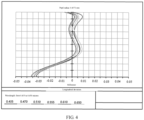
FIG 8 is a third schematic diagram of a field curvature/distortion curve of an optical lens according to an embodiment of this application; -
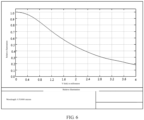
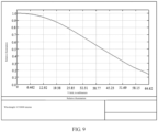
FIG 9 is a third curve chart of a relative illumination of an optical lens according to an embodiment of this application; and -
FIG 10 is a third curve chart of a longitudinal deviation of an optical lens according to an embodiment of this application. - The following clearly and completely describes the technical solutions in the embodiments of this application in conjunction with the accompanying drawings in the embodiments of this application. Apparently, the described embodiments are some but not all of the embodiments of this application. All other embodiments obtained by a person of ordinary skill in the art based on the embodiments of this application without creative efforts shall fall within the protection scope of this application.
- The terms "first", "second", and the like in the description and the claims of this application are used to distinguish between similar objects instead of describing a specific order or sequence. It should be understood that data used in this way may be interchangeable in an appropriate case, so that the embodiments of this application can be implemented in a sequence other than those shown or described herein, and objects distinguished by "first" and "second" are generally of a same type, and a quantity of objects is not limited. For example, there may be one or more first targets. In addition, in the specification and the claims, "and/or" represents at least one of connected objects, and a character "/" generally represents an "or" relationship between associated objects.
- Before describing the optical lens of the embodiments of this application in detail, in order to facilitate understanding, a conversion relationship between the equivalent focal length and the field of view (FOV) is briefly explained, as shown in Table 1.
Table 1 Equivalent focal length (mm) DFOV (degree) HFOV (degree) 11.0 126.1 117.1 12.0 122 112.6 13.0 118.0 108.3 14.0 114.2 104.3 15.0 110.5 100.4 16.0 107.0 96.7 17.0 103.7 93.3 18.0 100.5 90.0 - The DFOV represents a horizontal field of view, and the DFOV represents a vertical field of view.
- As can be seen from the above table, a smaller equivalent focal length herein indicates a larger field of view. In addition, a larger size of the photosensitive element indicates high image quality of the picture. However, the existing electronic device has a dilemma in the configuration of ultra wide lens, that is, the requirements on the equivalent focal length and the size of the photosensitive element cannot be satisfied at the same time to achieve high image quality at a large angle of view.
- To solve the foregoing problem, an embodiment of this application provides an optical lens, an optical module, and an electronic device.
- With reference to the accompanying drawings, the following describes in detail an optical lens in the embodiments of this application based on specific embodiments and application scenarios thereof.
- As shown in
FIG 1, FIG 1 is a schematic diagram of a hardware structure of an optical lens according to an embodiment of this application. The optical lens sequentially includes, from an object side to an image side along an optical axis: - a
first lens 1 with a negative bending force, where an object side surface of thefirst lens 1 is convex, and an image side surface of thefirst lens 1 is concave; - a
second lens 2 with a positive bending force, where an object side surface of thesecond lens 2 is convex, and an image side surface of thesecond lens 2 is concave; - a
third lens 3 with a positive bending force, where an object side surface of thethird lens 3 is convex, and an image side surface of thethird lens 3 is concave; - a
fourth lens 4 with a positive bending force, where both an object side surface and an image side surface of thefourth lens 4 are convex; - a
fifth lens 5 with a negative bending force, where both an object side surface and an image side surface of thefifth lens 5 are concave; - a
sixth lens 6 with a positive bending force, where an object side surface of thesixth lens 6 is concave, and an image side surface of thesixth lens 6 is convex; - a
seventh lens 7 with a negative bending force, where an object side surface of theseventh lens 7 includes a first bending portion and a second bending portion, the first bending portion and the second bending portion are connected to form a convex surface, and an image side surface of theseventh lens 7 includes a third bending portion and a fourth bending portion, and the third bending portion and the fourth bending portion are connected to form a concave surface; - the optical lens satisfies the following relational expressions:





V1 is a dispersion coefficient of thefirst lens 1, V2 is a dispersion coefficient of thesecond lens 2, V3 is a dispersion coefficient of thethird lens 3, V4 is a dispersion coefficient of thefourth lens 4, V5 is a dispersion coefficient of thefifth lens 5, V6 is a dispersion coefficient of thesixth lens 6, V7 is a dispersion coefficient of theseventh lens 7, N1 is a refractive index of thefirst lens 1, N2 is a refractive index of thesecond lens 2, N3 is a refractive index of thethird lens 3, N4 is a refractive index of thefourth lens 4, N5 is a refractive index of thefifth lens 5, N6 is a refractive index of thesixth lens 6, and N7 is a refractive index of theseventh lens 7. - It should be noted that the object side surface of the lens specifically refers to a surface away from the photosensitive element, and the image side surface of the lens specifically refers to a surface close to the photosensitive element.
- It should be noted that the object side surface of the
seventh lens 7 includes a first bending portion and a second bending portion, the first bending portion and the second bending portion are connected to form a convex surface, and an image side surface of theseventh lens 7 includes a third bending portion and a fourth bending portion, and the third bending portion and the fourth bending portion are connected to form a concave surface. This indicates that the seventh lens has two curvature inversions, so that a chief ray angle (Chief Ray Angle, CRA) of thephotosensitive element 8 arranged on the image side surface of the seventh lens can be satisfied. - N1 < N2 herein indicates that the
first lens 1 is a lens with low refractive index, and thesecond lens 2 is a lens with high refractive index, which can reduce the cost and may not destroy dispersion; N2 > N3 indicates that thesecond lens 2 is a lens with high refractive index, and thethird lens 3 is a lens with low refractive index, which can reduce the cost and may not destroy dispersion; N4 < N5 indicates that thethird lens 3 and thefourth lens 4 are both lenses with low refractive index, which can reduce the cost; thefourth lens 4 is a lens with low refractive index, and thefifth lens 5 is a lens with high refractive index, which can reduce the cost and may not destroy dispersion; N6 < N5 indicates that thefifth lens 5 is a lens with high refractive index, and thesixth lens 6 is a lens with low refractive index, which can reduce the cost and may not destroy dispersion; N6 < N7 indicates that thesixth lens 6 is a lens with low refractive index, and theseventh lens 7 is a lens with high refractive index, which can reduce the cost and may not destroy dispersion. - The optical lens in the embodiments of this application sequentially includes, from an object side to an image side along an optical axis: a first lens with a negative bending force, where an object side surface of the first lens is convex, and an image side surface of the first lens is concave; a second lens with a positive bending force, where an object side surface of the second lens is convex, and an image side surface of the second lens is concave; a third lens with a positive bending force, where an object side surface of the third lens is convex, and an image side surface of the third lens is concave; a fourth lens with a positive bending force, where both an object side surface and an image side surface of the fourth lens are convex; a fifth lens with a negative bending force, where both an object side surface and an image side surface of the fifth lens are concave; a sixth lens with a positive bending force, where an object side surface of the sixth lens is concave, and an image side surface of the sixth lens is convex; and a seventh lens with a negative bending force, where an object side surface of the seventh lens includes a first bending portion and a second bending portion, the first bending portion and the second bending portion are connected to form a convex surface, and an image side surface of the seventh lens includes a third bending portion and a fourth bending portion, and the third bending portion and the fourth bending portion are connected to form a concave surface. In this way, the optical lens with the above structure can satisfy the requirements on the equivalent focal length and the size of the photosensitive element at the same time, and the optical lens can be used to shoot a picture with large angle of view and high image quality, thus meeting shooting requirements of the user.
- As an optional implementation, the optical lens satisfies the following relational expressions:


R1 is a radius of the object side surface of thefirst lens 1, R2 is a radius of the image side surface of thefirst lens 1, R3 is a radius of the object side surface of thesecond lens 2, R4 is a radius of the image side surface of thesecond lens 2, R5 is a radius of the object side surface of thethird lens 3, R6 is a radius of the image side surface of thethird lens 3, R7 is a radius of the object side surface of thefourth lens 4, R8 is a radius of the image side surface of thefourth lens 4, R9 is a radius of the object side surface of thefifth lens 5, R10 is a radius of the image side surface of thefifth lens 5, R11 is a radius of the object side surface of thesixth lens 6, R12 is a radius of the image side surface of thesixth lens 6, R13 is a radius of the object side surface of theseventh lens 7, and R14 is a radius of the image side surface of theseventh lens 7. - It should be noted that 8.6 mm < R1 < 23.1 mm, and the object side surface of the
first lens 1 is convex, so that a ghost image-like stray light can be effectively avoided, and the dispersion can be effectively suppressed by using a lens with low refractive index. - Further, the optical lens satisfies the following relational expressions:

- f1 is a focal length of the
first lens 1, f2 is a focal length of thesecond lens 2, f3 is a focal length of thethird lens 3, f4 is a focal length of thefourth lens 4, f5 is a focal length of thefifth lens 5, f6 is a focal length of thesixth lens 6, and f7 is a focal length of theseventh lens 7; and - the optical lens further includes an aperture 9 arranged between the
third lens 3 and thefourth lens 4. - It should be noted that the aperture 9 is arranged between the
third lens 3 and thefourth lens 4, to effectively control an aberration and to be of good manufacturing sensitivity, that is, to have a relatively large field of view and image height size. - The optical module herein including the optical lens includes a
light filter 10 which is located between theseventh lens 7 and thephotosensitive element 8. Thelight filter 10 may be an infrared light filter, which is suitable for thephotosensitive element 8 with a diagonal length from 8.0 mm to 8.4 mm for effective imaging, and is suitable for visible light with a wavelength range from 400 nm to 700 nm. - Further, the optical lens satisfies the following relational expressions:

CT1 is a central thickness of thefirst lens 1 on the optical axis, CT2 is a central thickness of thesecond lens 2 on the optical axis, CT3 is a central thickness of thethird lens 3 on the optical axis, CT4 is a central thickness of thefourth lens 4 on the optical axis, CT5 is a central thickness of thefifth lens 5 on the optical axis, CT6 is a central thickness of thesixth lens 6 on the optical axis, and CT7 is a central thickness of theseventh lens 7 on the optical axis. - In this implementation, an optical lens meeting the foregoing size range is adopted with a small optical distortion. Specifically, -2.5% < Optical distortion < 1.5%, which is corresponding to the field of view distortion diagram shown in
FIG 2 . Relative illumination > 14.5%, as shown inFIG 3 . SeeFIG 4 for on-axis chromatic aberration, HFOV = 117 degrees, F2.2, 1.9 mm < focal length EFL < 2.0 mm. - An aspheric equation used is as follows, and parameters in specific implementation are shown in Table 2 in mm. Conic is a value of k in the aspheric equation.

Table 2 Annotation Curvature radius Thickness Radius Conic Material Nd/Abbe Lens 1 15.01 0.612 3.265 17.795 1.54/55.98 1.60 0.761 1.719 -1.533 Lens 2 3.45 0.599 1.547 1.818 1.67/19.24 4.56 0.453 1.114 7.350 Lens 3 4.40 0.321 0.966 -24.910 1.54/55.98 6.93 0.203 0.828 -85.682 Aperture -0.067 0.646 Lens 4 3.37 0.856 0.697 3.754 1.54/55.98 -1.41 0.041 0.928 -19.291 Lens 5 6.64 0.289 0.991 -4.772 1.67/19.24 2.35 0.719 1.313 -7.597 Lens 6 -3.68 0.826 1.669 0.647 1.54/55.98 -0.83 0.050 1.956 -4.529 Lens 7 2.74 0.437 2.755 -0.269 1.64/23.53 0.81 0.674 3.110 -5.912 Light filter 0.210 3.782 A4 A6 A8 A10 A12 A14 A16 1.8339E-03 2.2147E-03 -6.0843E-04 8.3238E-05 -5.7770E-06 1.6794E-07 -5.6031E-13 2.5098E-02 -4.6840E-03 2.2060E-02 -1.1149E-02 3.6892E-03 -5.9192E-04 7.4488E-08 4.1047E-02 1.8275E-02 -1.1405E-02 1.6662E-02 -1.0978E-02 1.8656E-03 5.2744E-05 1.3537E-01 -3.0940E-02 1.4103E-01 -1.6805E-01 7.1396E-02 -4.0643E-03 1.7491E-04 2.0545E-04 -1.2972E-01 -1.6076E-01 3.1034E-01 -1.9782E-01 6.1971E-02 -7.2758E-05 -1.9872E-04 -1.3382E-01 -3.0066E-01 1.0694E+00 -1.2959E+00 7.0572E-01 5.9128E-03 7.8232E-02 -1.8809E-01 5.2884E-01 -1.0490E+00 7.8666E-01 8.6371E-02 -1.7317E-04 -4.5728E-01 8.5520E-01 -1.2596E+00 1.0490E+00 -4.3592E-01 1.1613E-02 1.5072E-02 -4.6017E-05 -7.3935E-01 2.0227E+00 -3.2921E+00 2.7900E+00 -1.0456E+00 -3.6702E-04 -9.7555E-02 5.8877E-02 -3.7789E-02 1.1004E-02 -1.1098E-03 4.0874E-05 -8.5527E-06 4.8400E-02 -3.0615E-02 6.1340E-03 1.0727E-03 -1.0320E-04 -1.2568E-04 1.4613E-06 -9.1610E-02 7.8088E-02 -4.2164E-02 1.5828E-02 -3.2432E-03 2.6100E-04 -8.9580E-08 -1.3384E-01 3.3464E-02 -5.7284E-03 7.0544E-04 -6.6428E-05 4.2712E-06 -1.3273E-07 -5.3309E-02 1.3200E-02 -2.4535E-03 2.6960E-04 -1.4725E-05 1.0536E-07 1.4849E-08 - As an optional implementation, the optical lens satisfies the following relational expressions:


R1 is a radius of the object side surface of thefirst lens 1, R2 is a radius of the image side surface of thefirst lens 1, R3 is a radius of the object side surface of thesecond lens 2, R4 is a radius of the image side surface of thesecond lens 2, R5 is a radius of the object side surface of thethird lens 3, R6 is a radius of the image side surface of thethird lens 3, R7 is a radius of the object side surface of thefourth lens 4, R8 is a radius of the image side surface of thefourth lens 4, R9 is a radius of the object side surface of thefifth lens 5, R10 is a radius of the image side surface of thefifth lens 5, R11 is a radius of the object side surface of thesixth lens 6, R12 is a radius of the image side surface of thesixth lens 6, R13 is a radius of the object side surface of theseventh lens 7, and R14 is a radius of the image side surface of theseventh lens 7. - It should be noted that 4.1 mm < R1 < 11 mm, and the object side surface of the
first lens 1 is convex, so that a ghost image-like stray light can be effectively avoided, and the dispersion can be effectively suppressed by using a lens with low refractive index. - Further, the optical lens satisfies the following relational expressions:

- f1 is a focal length of the
first lens 1, f2 is a focal length of thesecond lens 2, f3 is a focal length of thethird lens 3, f4 is a focal length of thefourth lens 4, f5 is a focal length of thefifth lens 5, f6 is a focal length of thesixth lens 6, and f7 is a focal length of theseventh lens 7; and - the optical lens further includes an aperture arranged between the
third lens 3 and thefourth lens 4. - It should be noted that the aperture 9 is arranged between the
third lens 3 and thefourth lens 4, to effectively control an aberration and to be of good manufacturing sensitivity, that is, to have a relatively large field of view and image height size. - The optical module herein including the optical lens includes a
light filter 10 which is located between theseventh lens 7 and thephotosensitive element 8. Thelight filter 10 may be an infrared light filter, which is suitable for thephotosensitive element 8 with a diagonal length from 8.0 mm to 8.4 mm for effective imaging, and is suitable for visible light with a wavelength range from 400 nm to 700 nm. - Further, the optical lens satisfies the following relational expressions:

CT1 is a central thickness of thefirst lens 1 on the optical axis, CT2 is a central thickness of thesecond lens 2 on the optical axis, CT3 is a central thickness of thethird lens 3 on the optical axis, CT4 is a central thickness of thefourth lens 4 on the optical axis, CT5 is a central thickness of thefifth lens 5 on the optical axis, CT6 is a central thickness of thesixth lens 6 on the optical axis, and CT7 is a central thickness of theseventh lens 7 on the optical axis. - In this implementation, an optical lens meeting the foregoing size range is adopted with a small optical distortion. Specifically, -3% < Optical distortion < 2%, which is corresponding to the field of view distortion diagram shown in
FIG 5 . Relative illumination > 17.5%, as shown inFIG 6 . SeeFIG 7 for on-axis chromatic aberration, HFOV = 112 degrees, F2.2, 1.9 mm < focal length EFL < 2.2 mm. - An aspheric equation used is as follows, and parameters in specific implementation are shown in Table 3 in mm.
- Conic is a value of k in the aspheric equation.

Table 3 Annotation Curvature radius Thickness Radius Conic Material Nd/Abbe Lens 1 7.147 0.383 2.813 5.197 1.54/55.98 1.585 0.740 1.658 -1.602 Lens 2 3.782 0.549 1.446 4.922 1.67/19.24 4.598 0.405 1.000 20.075 Lens 3 4.356 0.309 0.962 0.319 1.54/55.98 7.285 0.223 0.847 -66.625 Aperture -0.067 0.681 Lens 4 3.519 0.905 0.710 -22.303 1.54/55.98 -1.391 0.045 0.943 -13.086 Lens 5 6.889 0.312 1.006 -156.166 1.67/19.24 2.353 0.719 1.381 0.136 Lens 6 -2.966 0.884 1.620 -0.108 1.54/55.98 -0.817 0.044 1.941 -4.353 Lens 7 2.834 0.450 2.885 -0.143 1.64/23.53 0.802 0.690 3.235 -5.808 Light filter 0.210 3.956 A4 A6 A8 A10 A12 A14 A16 -3.1866E-03 2.4055E-03 -5.0869E-04 7.7565E-05 -7.4400E-06 3.3069E-07 0.0000E+00 3.2111E-02 -9.6591E-03 2.2761E-02 -1.3793E-02 5.3743E-03 -8.1370E-04 0.0000E+00 5.9161E-02 9.9495E-03 -9.6578E-03 1.1162E-02 -4.6391E-03 1.4396E-04 0.0000E+00 1.6723E-01 -5.4682E-02 1.0317E-01 -1.0234E-02 -8.8537E-02 5.0503E-02 0.0000E+00 0.0000E+00 -1.4135E-01 -7.1823E-02 7.2738E-02 4.8641E-02 -2.1814E-02 0.0000E+00 0.0000E+00 -1.7030E-01 -1.8737E-02 7.5699E-02 2.0194E-01 -1.4507E-01 0.0000E+00 1.4491E-01 -1.9148E-01 2.1718E-01 -1.1065E-01 -1.6275E-01 1.8832E-01 0.0000E+00 -3.5093E-01 4.7545E-01 -5.3545E-01 2.3137E-01 5.0934E-02 -7.1480E-02 0.0000E+00 0.0000E+00 -3.4307E-01 5.3895E-01 -6.3597E-01 4.1154E-01 -1.6423E-01 0.0000E+00 -1.5034E-01 7.6507E-02 -5.0865E-02 2.1449E-02 -4.4636E-03 2.7813E-04 0.0000E+00 3.3667E-02 -3.6280E-02 1.3371E-02 1.1740E-03 -9.8002E-04 1.8640E-05 0.0000E+00 -1.0410E-01 7.0592E-02 -3.9138E-02 1.6280E-02 -3.5053E-03 2.8577E-04 0.0000E+00 -1.3033E-01 3.3647E-02 -5.8960E-03 6.9555E-04 -6.4353E-05 4.6283E-06 -1.7408E-07 -4.8125E-02 1.2079E-02 -2.2631E-03 2.5432E-04 -1.4800E-05 1.8861E-07 1.0882E-08 - As an optional implementation, the optical lens satisfies the following relational expressions:


R1 is a radius of the object side surface of thefirst lens 1, R2 is a radius of the image side surface of thefirst lens 1, R3 is a radius of the object side surface of thesecond lens 2, R4 is a radius of the image side surface of thesecond lens 2, R5 is a radius of the object side surface of thethird lens 3, R6 is a radius of the image side surface of thethird lens 3, R7 is a radius of the object side surface of thefourth lens 4, R8 is a radius of the image side surface of thefourth lens 4, R9 is a radius of the object side surface of thefifth lens 5, R10 is a radius of the image side surface of thefifth lens 5, R11 is a radius of the object side surface of thesixth lens 6, R12 is a radius of the image side surface of thesixth lens 6, R13 is a radius of the object side surface of theseventh lens 7, and R14 is a radius of the image side surface of theseventh lens 7. - It should be noted that 8.6 mm < R1 < 23 mm, and the object side surface of the
first lens 1 is convex, so that a ghost image-like stray light can be effectively avoided, and the dispersion can be effectively suppressed by using a lens with low refractive index. - Further, the optical lens satisfies the following relational expressions:

- f1 is a focal length of the
first lens 1, f2 is a focal length of thesecond lens 2, f3 is a focal length of thethird lens 3, f4 is a focal length of thefourth lens 4, f5 is a focal length of thefifth lens 5, f6 is a focal length of thesixth lens 6, and f7 is a focal length of theseventh lens 7; and - the optical lens further includes an aperture arranged between the
third lens 3 and thefourth lens 4. - It should be noted that the aperture 9 is arranged between the
third lens 3 and thefourth lens 4, to effectively control an aberration and to be of good manufacturing sensitivity, that is, to have a relatively large field of view and image height size. - The optical module herein including the optical lens includes a
light filter 10 which is located between theseventh lens 7 and thephotosensitive element 8. Thelight filter 10 may be an infrared light filter, which is suitable for thephotosensitive element 8 with a diagonal length from 8.0 mm to 8.4 mm for effective imaging, and is suitable for visible light with a wavelength range from 400 nm to 700 nm. - Further, the optical lens satisfies the following relational expressions:

CT1 is a central thickness of thefirst lens 1 on the optical axis, CT2 is a central thickness of thesecond lens 2 on the optical axis, CT3 is a central thickness of thethird lens 3 on the optical axis, CT4 is a central thickness of thefourth lens 4 on the optical axis, CT5 is a central thickness of thefifth lens 5 on the optical axis, CT6 is a central thickness of thesixth lens 6 on the optical axis, and CT7 is a central thickness of theseventh lens 7 on the optical axis. - In this implementation, an optical lens meeting the foregoing size range is adopted with a small optical distortion. Specifically, -3.5% < Optical distortion < 1%, which is corresponding to the field of view distortion diagram shown in
FIG 8 . Relative illumination > 13.4%, as shown inFIG 9 . SeeFIG 10 for on-axis chromatic aberration, HFOV = 117 degrees, F2.2, 1.9 mm < focal length EFL < 2.2 mm. - An aspheric equation used is as follows, and parameters in specific implementation are shown in Table 4 in mm. Conic is a value of k in the aspheric equation.

Table 4 Annotation Curvature radius Thickness Radius Conic Material Nd/Abbe Lens 1 14.899 0.610 3.247 18.263 1.54/55.98 1.617 0.723 1.704 -1.506 Lens 2 3.400 0.616 1.549 1.798 1.67/19.24 4.417 0.414 1.086 7.257 Lens 3 4.555 0.346 0.955 -27.132 1.54/55.98 6.548 0.190 0.809 -102.557 Aperture -0.067 0.636 Lens 4 3.246 0.818 0.700 3.585 1.54/55.98 -1.423 0.041 0.920 -20.417 Lens 5 7.965 0.344 0.982 21.713 1.67/19.24 2.479 0.685 1.343 -4.233 Lens 6 -3.552 0.815 1.690 -1.403 1.54/55.98 -0.847 0.050 1.993 -4.241 Lens 7 2.773 0.488 2.989 -0.252 1.64/23.53 0.843 0.654 3.248 -5.886 Light filter 0.210 4.017 A4 A6 A8 A10 A12 A14 A16 1.6717E-03 2.2316E-03 -6.0726E-04 8.3211E-05 -5.7889E-06 1.6764E-07 1.4820E-10 2.4451E-02 -4.2097E-03 2.2202E-02 -1.1083E-02 3.6529E-03 -6.0279E-04 -5.6906E-07 4.0471E-02 1.7912E-02 -1.2223E-02 1.6447E-02 -1.0983E-02 1.8801E-03 6.6582E-05 1.3842E-01 -3.5595E-02 1.4150E-01 -1.7196E-01 7.0048E-02 3.7162E-03 -1.7473E-03 -1.6975E-03 -1.3339E-01 -1.5762E-01 3.3418E-01 -2.0899E-01 -1.6708E-02 6.3973E-02 -1.0898E-03 -1.3797E-01 -3.1083E-01 1.0694E+00 -1.2872E+00 6.4562E-01 1.0557E-01 7.8356E-02 -1.9178E-01 5.2708E-01 -1.0584E+00 7.6979E-01 8.3740E-02 7.2447E-02 -4.6447E-01 8.9493E-01 -1.2958E+00 1.0158E+00 -4.0659E-01 5.5474E-02 -4.3682E-02 1.2647E-02 -7.4070E-01 2.0012E+00 -3.2776E+00 2.8035E+00 -1.0576E+00 -1.8175E-02 -1.0752E-01 6.3542E-02 -3.5757E-02 9.2411E-03 -1.3824E-03 5.2651E-04 -1.2139E-04 5.4769E-02 -3.3510E-02 7.5609E-03 5.6161E-04 -1.1805E-04 -6.5109E-05 -1.3057E-05 -9.6885E-02 8.4793E-02 -4.2704E-02 1.5663E-02 -3.2564E-03 2.6337E-04 7.8935E-07 -1.3193E-01 3.3434E-02 -5.7303E-03 7.0492E-04 -6.6499E-05 4.2679E-06 -1.3160E-07 -5.2675E-02 1.3235E-02 -2.4737E-03 2.7234E-04 -1.4633E-05 8.5501E-08 1.4699E-08 - It should be noted that in the foregoing table,
Lens 1 specifically refers to thefirst lens 1,Lens 2 specifically refers to thesecond lens 2,Lens 3 specifically refers to thethird lens 3,Lens 4 specifically refers to thefourth lens 4,Lens 5 specifically refers to thefifth lens 5,Lens 6 specifically refers to thesixth lens 6, andLens 7 specifically refers to theseventh lens 7. - Optionally, the
first lens 1, thesecond lens 2, thethird lens 3, thefourth lens 4, thefifth lens 5, thesixth lens 6, and theseventh lens 7 are all aspheric lenses. - The optical lens in the embodiments of this application sequentially includes, from an object side to an image side along an optical axis: a first lens with a negative bending force, where an object side surface of the first lens is convex, and an image side surface of the first lens is concave; a second lens with a positive bending force, where an object side surface of the second lens is convex, and an image side surface of the second lens is concave; a third lens with a positive bending force, where an object side surface of the third lens is convex, and an image side surface of the third lens is concave; a fourth lens with a positive bending force, where both an object side surface and an image side surface of the fourth lens are convex; a fifth lens with a negative bending force, where both an object side surface and an image side surface of the fifth lens are concave; a sixth lens with a positive bending force, where an object side surface of the sixth lens is concave, and an image side surface of the sixth lens is convex; and a seventh lens with a negative bending force, where an object side surface of the seventh lens includes a first bending portion and a second bending portion, the first bending portion and the second bending portion are connected to form a convex surface, and an image side surface of the seventh lens includes a third bending portion and a fourth bending portion, and the third bending portion and the fourth bending portion are connected to form a concave surface. In this way, the optical lens with the above structure can satisfy the requirements on the equivalent focal length and the size of the photosensitive element at the same time, and the optical lens can be used to shoot a picture with large angle of view and high image quality, thus meeting shooting requirements of the user.
- An embodiment of this application further provides an optical module, including the optical lens described in the foregoing embodiment; a
photosensitive element 8; and alight filter 10 arranged between aseventh lens 7 of the optical lens and thephotosensitive element 8. - Optionally, a long diagonal line of the
photosensitive element 8 is greater than or equal to 1/2.0 inch, and an equivalent focal length of the optical lens is greater than or equal to 11 mm and less than or equal to 12 mm. In this way, it can be ensured that the optical module can have a shorter equivalent focal length and a larger photosensitive element at the same time. - An embodiment of this application further provides an electronic device, including the optical module as described above.
- It should be noted that, in this specification, the terms "include", "comprise", or any other variant thereof is intended to cover a non-exclusive inclusion, so that a process, a method, an article, or an apparatus that includes a list of elements not only includes those elements but also includes other elements which are not expressly listed, or further includes elements inherent to such process, method, article, or apparatus. An element limited by "includes a ..." does not, without more constraints, preclude the presence of additional identical elements in the process, method, article, or apparatus that includes the element.
- The embodiments of this application are described above with reference to the accompanying drawings, but this application is not limited to the foregoing specific implementations. The foregoing specific implementations are merely schematic instead of restrictive. Under enlightenment of this application, a person of ordinary skills in the art may make many forms without departing from aims and the protection scope of claims of this application, all of which fall within the protection scope of this application.
- The foregoing descriptions are merely the preferred implementations of the present disclosure. It should be noted that those of ordinary skill in the art may further make several improvements and refinements without departing from the principles described in the present disclosure, and these improvements and refinements also fall within the protection scope of the present disclosure.
Claims (14)
- An optical lens, sequentially comprising, from an object side to an image side along an optical axis:a first lens with a negative bending force, wherein an object side surface of the first lens is convex, and an image side surface of the first lens is concave;a second lens with a positive bending force, wherein an object side surface of the second lens is convex, and an image side surface of the second lens is concave;a third lens with a positive bending force, wherein an object side surface of the third lens is convex, and an image side surface of the third lens is concave;a fourth lens with a positive bending force, wherein both an object side surface and an image side surface of the fourth lens are convex;a fifth lens with a negative bending force, wherein both an object side surface and an image side surface of the fifth lens are concave;a sixth lens with a positive bending force, wherein an object side surface of the sixth lens is concave, and an image side surface of the sixth lens is convex;a seventh lens with a negative bending force, wherein an object side surface of the seventh lens comprises a first bending portion and a second bending portion, the first bending portion and the second bending portion are connected to form a convex surface, and an image side surface of the seventh lens comprises a third bending portion and a fourth bending portion, and the third bending portion and the fourth bending portion are connected to form a concave surface;the optical lens satisfies the following relational expressions:


 V1 is a dispersion coefficient of the first lens, V2 is a dispersion coefficient of the second lens, V3 is a dispersion coefficient of the third lens, V4 is a dispersion coefficient of the fourth lens, V5 is a dispersion coefficient of the fifth lens, V6 is a dispersion coefficient of the sixth lens, V7 is a dispersion coefficient of the seventh lens, N1 is a refractive index of the first lens, N2 is a refractive index of the second lens, N3 is a refractive index of the third lens, N4 is a refractive index of the fourth lens, N5 is a refractive index of the fifth lens, N6 is a refractive index of the sixth lens, and N7 is a refractive index of the seventh lens.
 - The optical lens according to claim 1, wherein the optical lens satisfies the following relational expressions:


R1 is a radius of the object side surface of the first lens, R2 is a radius of the image side surface of the first lens, R3 is a radius of the object side surface of the second lens, R4 is a radius of the image side surface of the second lens, R5 is a radius of the object side surface of the third lens, R6 is a radius of the image side surface of the third lens, R7 is a radius of the object side surface of the fourth lens, R8 is a radius of the image side surface of the fourth lens, R9 is a radius of the object side surface of the fifth lens, R10 is a radius of the image side surface of the fifth lens, R11 is a radius of the object side surface of the sixth lens, R12 is a radius of the image side surface of the sixth lens, R13 is a radius of the object side surface of the seventh lens, and R14 is a radius of the image side surface of the seventh lens. - The optical lens according to claim 2, wherein the optical lens satisfies the following relational expressions:
 f1 is a focal length of the first lens, f2 is a focal length of the second lens, f3 is a focal length of the third lens, f4 is a focal length of the fourth lens, f5 is a focal length of the fifth lens, f6 is a focal length of the sixth lens, and f7 is a focal length of the seventh lens; andthe optical lens further comprises an aperture arranged between the third lens and the fourth lens.
 - The optical lens according to claim 2, wherein the optical lens satisfies the following relational expressions:

CT1 is a central thickness of the first lens on the optical axis, CT2 is a central thickness of the second lens on the optical axis, CT3 is a central thickness of the third lens on the optical axis, CT4 is a central thickness of the fourth lens on the optical axis, CT5 is a central thickness of the fifth lens on the optical axis, CT6 is a central thickness of the sixth lens on the optical axis, and CT7 is a central thickness of the seventh lens on the optical axis. - The optical lens according to claim 1, wherein the optical lens satisfies the following relational expressions:


R1 is a radius of the object side surface of the first lens, R2 is a radius of the image side surface of the first lens, R3 is a radius of the object side surface of the second lens, R4 is a radius of the image side surface of the second lens, R5 is a radius of the object side surface of the third lens, R6 is a radius of the image side surface of the third lens, R7 is a radius of the object side surface of the fourth lens, R8 is a radius of the image side surface of the fourth lens, R9 is a radius of the object side surface of the fifth lens, R10 is a radius of the image side surface of the fifth lens, R11 is a radius of the object side surface of the sixth lens, R12 is a radius of the image side surface of the sixth lens, R13 is a radius of the object side surface of the seventh lens, and R14 is a radius of the image side surface of the seventh lens. - The optical lens according to claim 5, wherein the optical lens satisfies the following relational expressions:
 f1 is a focal length of the first lens, f2 is a focal length of the second lens, f3 is a focal length of the third lens, f4 is a focal length of the fourth lens, f5 is a focal length of the fifth lens, f6 is a focal length of the sixth lens, and f7 is a focal length of the seventh lens; andthe optical lens further comprises an aperture arranged between the third lens and the fourth lens.
 - The optical lens according to claim 5, wherein the optical lens satisfies the following relational expressions:

CT1 is a central thickness of the first lens on the optical axis, CT2 is a central thickness of the second lens on the optical axis, CT3 is a central thickness of the third lens on the optical axis, CT4 is a central thickness of the fourth lens on the optical axis, CT5 is a central thickness of the fifth lens on the optical axis, CT6 is a central thickness of the sixth lens on the optical axis, and CT7 is a central thickness of the seventh lens on the optical axis. - The optical lens according to claim 1, wherein the optical lens satisfies the following relational expressions:





R1 is a radius of the object side surface of the first lens, R2 is a radius of the image side surface of the first lens, R3 is a radius of the object side surface of the second lens, R4 is a radius of the image side surface of the second lens, R5 is a radius of the object side surface of the third lens, R6 is a radius of the image side surface of the third lens, R7 is a radius of the object side surface of the fourth lens, R8 is a radius of the image side surface of the fourth lens, R9 is a radius of the object side surface of the fifth lens, R10 is a radius of the image side surface of the fifth lens, R11 is a radius of the object side surface of the sixth lens, R12 is a radius of the image side surface of the sixth lens, R13 is a radius of the object side surface of the seventh lens, and R14 is a radius of the image side surface of the seventh lens. - The optical lens according to claim 8, wherein the optical lens satisfies the following relational expressions:
 f1 is a focal length of the first lens, f2 is a focal length of the second lens, f3 is a focal length of the third lens, f4 is a focal length of the fourth lens, f5 is a focal length of the fifth lens, f6 is a focal length of the sixth lens, and f7 is a focal length of the seventh lens; andthe optical lens further comprises an aperture arranged between the third lens and the fourth lens.
 - The optical lens according to claim 8, wherein the optical lens satisfies the following relational expressions:

CT1 is a central thickness of the first lens on the optical axis, CT2 is a central thickness of the second lens on the optical axis, CT3 is a central thickness of the third lens on the optical axis, CT4 is a central thickness of the fourth lens on the optical axis, CT5 is a central thickness of the fifth lens on the optical axis, CT6 is a central thickness of the sixth lens on the optical axis, and CT7 is a central thickness of the seventh lens on the optical axis. - The optical lens according to claim 1, wherein the first lens, the second lens, the third lens, the fourth lens, the fifth lens, the sixth lens, and the seventh lens are all aspheric lenses.
- An optical module, comprising:the optical lens according to any one of claims 1 to 11;a photosensitive element; anda light filter arranged between a seventh lens of the optical lens and the photosensitive element.
- The optical module according to claim 12, wherein a long diagonal line of the photosensitive element is greater than or equal to 1/2.0 inch, and an equivalent focal length of the optical lens is greater than or equal to 11 mm and less than or equal to 12 mm.
- An electronic device, comprising the optical module according to any one of claims 12 and 13.
Applications Claiming Priority (2)
| Application Number | Priority Date | Filing Date | Title |
|---|---|---|---|
| CN202011041048.9A CN112147765B (en) | 2020-09-28 | 2020-09-28 | Optical lens, optical module and electronic equipment |
| PCT/CN2021/119880 WO2022063171A1 (en) | 2020-09-28 | 2021-09-23 | Optical lens, optical module and electronic device |
Publications (3)
| Publication Number | Publication Date |
|---|---|
| EP4220268A1 true EP4220268A1 (en) | 2023-08-02 |
| EP4220268A4 EP4220268A4 (en) | 2024-04-03 |
| EP4220268B1 EP4220268B1 (en) | 2026-05-06 |
Family
ID=73894948
Family Applications (1)
| Application Number | Title | Priority Date | Filing Date |
|---|---|---|---|
| EP21871540.7A Active EP4220268B1 (en) | 2020-09-28 | 2021-09-23 | Optical lens, optical module and electronic device |
Country Status (4)
| Country | Link |
|---|---|
| US (1) | US12372748B2 (en) |
| EP (1) | EP4220268B1 (en) |
| CN (1) | CN112147765B (en) |
| WO (1) | WO2022063171A1 (en) |
Families Citing this family (4)
| Publication number | Priority date | Publication date | Assignee | Title |
|---|---|---|---|---|
| CN112147765B (en) | 2020-09-28 | 2022-10-28 | 维沃移动通信有限公司 | Optical lens, optical module and electronic equipment |
| US12501129B2 (en) * | 2021-07-16 | 2025-12-16 | Samsung Electro-Mechanics Co., Ltd. | Image sensor, camera module, and electronic device including the same |
| KR102933577B1 (en) * | 2021-08-30 | 2026-03-04 | 삼성전기주식회사 | Imaging Lens System |
| US12339520B2 (en) * | 2022-04-26 | 2025-06-24 | Changzhou Aac Raytech Optronics Co., Ltd. | Camera optical lens |
Family Cites Families (13)
| Publication number | Priority date | Publication date | Assignee | Title |
|---|---|---|---|---|
| JP5350831B2 (en) * | 2009-02-17 | 2013-11-27 | オリンパス株式会社 | Zoom lens and image pickup apparatus having the same |
| TWI449947B (en) * | 2012-08-13 | 2014-08-21 | Largan Precision Co Ltd | Image lens assembly system |
| CN107678130B (en) * | 2017-10-19 | 2020-01-17 | 瑞声科技(新加坡)有限公司 | Image pickup optical lens |
| JP6362201B1 (en) | 2017-11-18 | 2018-07-25 | エーエーシー テクノロジーズ ピーティーイー リミテッドAac Technologies Pte.Ltd. | Imaging optical lens |
| CN208705559U (en) * | 2018-08-02 | 2019-04-05 | 浙江舜宇光学有限公司 | Optical imaging lens |
| CN109298515B (en) * | 2018-12-11 | 2023-11-21 | 浙江舜宇光学有限公司 | Image pickup lens |
| CN211014809U (en) * | 2019-10-15 | 2020-07-14 | 浙江舜宇光学有限公司 | Optical imaging system |
| CN110824676B (en) * | 2019-12-24 | 2021-11-26 | 浙江舜宇光学有限公司 | Optical imaging lens |
| CN111198438B (en) * | 2020-03-05 | 2024-07-26 | 玉晶光电(厦门)有限公司 | Optical imaging lens |
| CN111399190A (en) * | 2020-05-26 | 2020-07-10 | 浙江舜宇光学有限公司 | Optical imaging lens |
| CN112147765B (en) * | 2020-09-28 | 2022-10-28 | 维沃移动通信有限公司 | Optical lens, optical module and electronic equipment |
| CN112698484B (en) * | 2020-12-30 | 2022-11-25 | 浙江舜宇光学有限公司 | Optical imaging lens |
| CN112764197B (en) * | 2021-01-13 | 2022-05-06 | 浙江舜宇光学有限公司 | camera lens |
-
2020
- 2020-09-28 CN CN202011041048.9A patent/CN112147765B/en active Active
-
2021
- 2021-09-23 EP EP21871540.7A patent/EP4220268B1/en active Active
- 2021-09-23 WO PCT/CN2021/119880 patent/WO2022063171A1/en not_active Ceased
-
2023
- 2023-03-22 US US18/125,100 patent/US12372748B2/en active Active
Also Published As
| Publication number | Publication date |
|---|---|
| EP4220268A4 (en) | 2024-04-03 |
| US20230236389A1 (en) | 2023-07-27 |
| CN112147765B (en) | 2022-10-28 |
| US12372748B2 (en) | 2025-07-29 |
| WO2022063171A1 (en) | 2022-03-31 |
| CN112147765A (en) | 2020-12-29 |
| EP4220268B1 (en) | 2026-05-06 |
Similar Documents
| Publication | Publication Date | Title |
|---|---|---|
| US11971522B2 (en) | Optical imaging lens assembly including six lenses of +−++−−, +−+−+−, +−−+−−, +−+++−, or +−++−+ refractive powers | |
| US11698514B2 (en) | Imaging lens assembly | |
| US12372748B2 (en) | Optical lens, optical module, and electronic device including seven lenses of −+++−+− refractive powers | |
| US10761289B2 (en) | Camera lens assembly and camera device | |
| US11630283B2 (en) | Optical imaging lens | |
| US11487049B2 (en) | Optical imaging lens group | |
| US11029501B2 (en) | Camera lens assembly | |
| US12174456B2 (en) | Optical imaging lens | |
| EP3901682A1 (en) | Optical lens group, image capturing device, and electronic device | |
| US20190121100A1 (en) | Optical imaging lens assembly | |
| US20180045923A1 (en) | Telephoto lens | |
| EP3896510A1 (en) | Optical system, image capturing device and electronic device | |
| US11054611B2 (en) | Optical imaging lens assembly | |
| US20140293447A1 (en) | Imaging lens and imaging apparatus including the imaging lens | |
| EP4194921A1 (en) | Optical system, lens module, and electronic device | |
| US12105263B2 (en) | Optical system, lens module, and electronic device | |
| US10866391B2 (en) | Imaging lens assembly | |
| US12003836B2 (en) | Optical system, lens module, and electronic device | |
| US11579407B2 (en) | Optical imaging lens assembly | |
| US20220043240A1 (en) | Optical imaging lens assembly | |
| US20190170983A1 (en) | Imaging lens assembly | |
| US20220236524A1 (en) | Optical imaging lens assembly | |
| EP3933476A1 (en) | Optical system, lens module and terminal device | |
| CN111338063B (en) | Optical systems, lens modules and electronic devices | |
| US11112584B2 (en) | Imaging lens assembly |
Legal Events
| Date | Code | Title | Description |
|---|---|---|---|
| STAA | Information on the status of an ep patent application or granted ep patent |
Free format text: STATUS: THE INTERNATIONAL PUBLICATION HAS BEEN MADE |
|
| PUAI | Public reference made under article 153(3) epc to a published international application that has entered the european phase |
Free format text: ORIGINAL CODE: 0009012 |
|
| STAA | Information on the status of an ep patent application or granted ep patent |
Free format text: STATUS: REQUEST FOR EXAMINATION WAS MADE |
|
| 17P | Request for examination filed |
Effective date: 20230323 |
|
| AK | Designated contracting states |
Kind code of ref document: A1 Designated state(s): AL AT BE BG CH CY CZ DE DK EE ES FI FR GB GR HR HU IE IS IT LI LT LU LV MC MK MT NL NO PL PT RO RS SE SI SK SM TR |
|
| DAV | Request for validation of the european patent (deleted) | ||
| DAX | Request for extension of the european patent (deleted) | ||
| A4 | Supplementary search report drawn up and despatched |
Effective date: 20240306 |
|
| RIC1 | Information provided on ipc code assigned before grant |
Ipc: G02B 9/64 20060101ALI20240229BHEP Ipc: G02B 13/18 20060101ALI20240229BHEP Ipc: G02B 13/06 20060101AFI20240229BHEP |
|
| GRAP | Despatch of communication of intention to grant a patent |
Free format text: ORIGINAL CODE: EPIDOSNIGR1 |
|
| STAA | Information on the status of an ep patent application or granted ep patent |
Free format text: STATUS: GRANT OF PATENT IS INTENDED |
|
| INTG | Intention to grant announced |
Effective date: 20251201 |
|
| GRAS | Grant fee paid |
Free format text: ORIGINAL CODE: EPIDOSNIGR3 |
|
| GRAA | (expected) grant |
Free format text: ORIGINAL CODE: 0009210 |
|
| STAA | Information on the status of an ep patent application or granted ep patent |
Free format text: STATUS: THE PATENT HAS BEEN GRANTED |
|
| AK | Designated contracting states |
Kind code of ref document: B1 Designated state(s): AL AT BE BG CH CY CZ DE DK EE ES FI FR GB GR HR HU IE IS IT LI LT LU LV MC MK MT NL NO PL PT RO RS SE SI SK SM TR |
|
| REG | Reference to a national code |
Ref country code: CH Ref legal event code: F10 Free format text: ST27 STATUS EVENT CODE: U-0-0-F10-F00 (AS PROVIDED BY THE NATIONAL OFFICE) Effective date: 20260506 Ref country code: GB Ref legal event code: FG4D |