EP4220224A1 - Method and device for detecting and tracking objects and driver assistance system - Google Patents
Method and device for detecting and tracking objects and driver assistance system Download PDFInfo
- Publication number
- EP4220224A1 EP4220224A1 EP22153358.1A EP22153358A EP4220224A1 EP 4220224 A1 EP4220224 A1 EP 4220224A1 EP 22153358 A EP22153358 A EP 22153358A EP 4220224 A1 EP4220224 A1 EP 4220224A1
- Authority
- EP
- European Patent Office
- Prior art keywords
- tracked
- objects
- candidate
- newly identified
- spatial coordinates
- Prior art date
- Legal status (The legal status is an assumption and is not a legal conclusion. Google has not performed a legal analysis and makes no representation as to the accuracy of the status listed.)
- Granted
Links
Images
Classifications
-
- G—PHYSICS
- G01—MEASURING; TESTING
- G01S—RADIO DIRECTION-FINDING; RADIO NAVIGATION; DETERMINING DISTANCE OR VELOCITY BY USE OF RADIO WAVES; LOCATING OR PRESENCE-DETECTING BY USE OF THE REFLECTION OR RERADIATION OF RADIO WAVES; ANALOGOUS ARRANGEMENTS USING OTHER WAVES
- G01S17/00—Systems using the reflection or reradiation of electromagnetic waves other than radio waves, e.g. lidar systems
- G01S17/88—Lidar systems specially adapted for specific applications
- G01S17/93—Lidar systems specially adapted for specific applications for anti-collision purposes
- G01S17/931—Lidar systems specially adapted for specific applications for anti-collision purposes of land vehicles
-
- G—PHYSICS
- G01—MEASURING; TESTING
- G01S—RADIO DIRECTION-FINDING; RADIO NAVIGATION; DETERMINING DISTANCE OR VELOCITY BY USE OF RADIO WAVES; LOCATING OR PRESENCE-DETECTING BY USE OF THE REFLECTION OR RERADIATION OF RADIO WAVES; ANALOGOUS ARRANGEMENTS USING OTHER WAVES
- G01S13/00—Systems using the reflection or reradiation of radio waves, e.g. radar systems; Analogous systems using reflection or reradiation of waves whose nature or wavelength is irrelevant or unspecified
- G01S13/66—Radar-tracking systems; Analogous systems
- G01S13/72—Radar-tracking systems; Analogous systems for two-dimensional [2D] tracking, e.g. combination of angle and range tracking, track-while-scan radar
- G01S13/723—Radar-tracking systems; Analogous systems for two-dimensional [2D] tracking, e.g. combination of angle and range tracking, track-while-scan radar by using numerical data
- G01S13/726—Multiple target tracking
-
- G—PHYSICS
- G01—MEASURING; TESTING
- G01S—RADIO DIRECTION-FINDING; RADIO NAVIGATION; DETERMINING DISTANCE OR VELOCITY BY USE OF RADIO WAVES; LOCATING OR PRESENCE-DETECTING BY USE OF THE REFLECTION OR RERADIATION OF RADIO WAVES; ANALOGOUS ARRANGEMENTS USING OTHER WAVES
- G01S13/00—Systems using the reflection or reradiation of radio waves, e.g. radar systems; Analogous systems using reflection or reradiation of waves whose nature or wavelength is irrelevant or unspecified
- G01S13/88—Radar or analogous systems specially adapted for specific applications
- G01S13/93—Radar or analogous systems specially adapted for specific applications for anti-collision purposes
- G01S13/931—Radar or analogous systems specially adapted for specific applications for anti-collision purposes of land vehicles
-
- G—PHYSICS
- G01—MEASURING; TESTING
- G01S—RADIO DIRECTION-FINDING; RADIO NAVIGATION; DETERMINING DISTANCE OR VELOCITY BY USE OF RADIO WAVES; LOCATING OR PRESENCE-DETECTING BY USE OF THE REFLECTION OR RERADIATION OF RADIO WAVES; ANALOGOUS ARRANGEMENTS USING OTHER WAVES
- G01S17/00—Systems using the reflection or reradiation of electromagnetic waves other than radio waves, e.g. lidar systems
- G01S17/66—Tracking systems using electromagnetic waves other than radio waves
-
- G—PHYSICS
- G01—MEASURING; TESTING
- G01S—RADIO DIRECTION-FINDING; RADIO NAVIGATION; DETERMINING DISTANCE OR VELOCITY BY USE OF RADIO WAVES; LOCATING OR PRESENCE-DETECTING BY USE OF THE REFLECTION OR RERADIATION OF RADIO WAVES; ANALOGOUS ARRANGEMENTS USING OTHER WAVES
- G01S17/00—Systems using the reflection or reradiation of electromagnetic waves other than radio waves, e.g. lidar systems
- G01S17/86—Combinations of lidar systems with systems other than lidar, radar or sonar, e.g. with direction finders
-
- G—PHYSICS
- G01—MEASURING; TESTING
- G01S—RADIO DIRECTION-FINDING; RADIO NAVIGATION; DETERMINING DISTANCE OR VELOCITY BY USE OF RADIO WAVES; LOCATING OR PRESENCE-DETECTING BY USE OF THE REFLECTION OR RERADIATION OF RADIO WAVES; ANALOGOUS ARRANGEMENTS USING OTHER WAVES
- G01S7/00—Details of systems according to groups G01S13/00, G01S15/00, G01S17/00
- G01S7/02—Details of systems according to groups G01S13/00, G01S15/00, G01S17/00 of systems according to group G01S13/00
- G01S7/28—Details of pulse systems
- G01S7/285—Receivers
- G01S7/295—Means for transforming co-ordinates or for evaluating data, e.g. using computers
- G01S7/2955—Means for determining the position of the radar coordinate system for evaluating the position data of the target in another coordinate system
-
- G—PHYSICS
- G01—MEASURING; TESTING
- G01S—RADIO DIRECTION-FINDING; RADIO NAVIGATION; DETERMINING DISTANCE OR VELOCITY BY USE OF RADIO WAVES; LOCATING OR PRESENCE-DETECTING BY USE OF THE REFLECTION OR RERADIATION OF RADIO WAVES; ANALOGOUS ARRANGEMENTS USING OTHER WAVES
- G01S13/00—Systems using the reflection or reradiation of radio waves, e.g. radar systems; Analogous systems using reflection or reradiation of waves whose nature or wavelength is irrelevant or unspecified
- G01S13/02—Systems using reflection of radio waves, e.g. primary radar systems; Analogous systems
- G01S13/50—Systems of measurement based on relative movement of target
- G01S13/58—Velocity or trajectory determination systems; Sense-of-movement determination systems
- G01S13/588—Velocity or trajectory determination systems; Sense-of-movement determination systems deriving the velocity value from the range measurement
-
- G—PHYSICS
- G01—MEASURING; TESTING
- G01S—RADIO DIRECTION-FINDING; RADIO NAVIGATION; DETERMINING DISTANCE OR VELOCITY BY USE OF RADIO WAVES; LOCATING OR PRESENCE-DETECTING BY USE OF THE REFLECTION OR RERADIATION OF RADIO WAVES; ANALOGOUS ARRANGEMENTS USING OTHER WAVES
- G01S13/00—Systems using the reflection or reradiation of radio waves, e.g. radar systems; Analogous systems using reflection or reradiation of waves whose nature or wavelength is irrelevant or unspecified
- G01S13/86—Combinations of radar systems with non-radar systems, e.g. sonar, direction finder
- G01S13/865—Combination of radar systems with lidar systems
-
- G—PHYSICS
- G01—MEASURING; TESTING
- G01S—RADIO DIRECTION-FINDING; RADIO NAVIGATION; DETERMINING DISTANCE OR VELOCITY BY USE OF RADIO WAVES; LOCATING OR PRESENCE-DETECTING BY USE OF THE REFLECTION OR RERADIATION OF RADIO WAVES; ANALOGOUS ARRANGEMENTS USING OTHER WAVES
- G01S13/00—Systems using the reflection or reradiation of radio waves, e.g. radar systems; Analogous systems using reflection or reradiation of waves whose nature or wavelength is irrelevant or unspecified
- G01S13/86—Combinations of radar systems with non-radar systems, e.g. sonar, direction finder
- G01S13/867—Combination of radar systems with cameras
-
- G—PHYSICS
- G01—MEASURING; TESTING
- G01S—RADIO DIRECTION-FINDING; RADIO NAVIGATION; DETERMINING DISTANCE OR VELOCITY BY USE OF RADIO WAVES; LOCATING OR PRESENCE-DETECTING BY USE OF THE REFLECTION OR RERADIATION OF RADIO WAVES; ANALOGOUS ARRANGEMENTS USING OTHER WAVES
- G01S13/00—Systems using the reflection or reradiation of radio waves, e.g. radar systems; Analogous systems using reflection or reradiation of waves whose nature or wavelength is irrelevant or unspecified
- G01S13/88—Radar or analogous systems specially adapted for specific applications
- G01S13/93—Radar or analogous systems specially adapted for specific applications for anti-collision purposes
- G01S13/931—Radar or analogous systems specially adapted for specific applications for anti-collision purposes of land vehicles
- G01S2013/9323—Alternative operation using light waves
Definitions
- the present invention relates to a method and a device for detecting and tracking objects in a surrounding of a vehicle.
- the invention further relates to a driver assistance system.
- Modern vehicles can comprise multiple sensors of different types, such as radar sensors, cameras, infrared sensors, lidar sensors and the like.
- a radar sensor can emit radar signals which are reflected by objects in a surrounding of the vehicle.
- the coordinates of the reflecting objects can be determined by analyzing the received radar signals.
- Each of the recognized objects can be tracked over time. For example, the moving directions or velocities of the tracked candidate objects can be determined.
- the driver assistance systems can inform the driver of possibly dangerous situations or can control functions of the vehicle, such as an adjustment of the speed or the steering angle of the vehicle.
- Tracking solutions are taking care of the association problem between objects detected in a subsequent frame by creating dynamic entities with a predefined lifespan.
- Filtering techniques like Kalman filtering
- the main steps are the following: prediction of the state of the observed objects for the next timestamp, the association between the predicted state of the object and the measurement at the next timestamp, and an update of the state of the observed object for further tracking.
- Implementation of radar detection systems may comprise rule-based filtering.
- Reliable locations may be identified as object candidates which are fed into a decision tree process to gain multi-layer probabilities.
- Bayesian classification methods can stabilize the output probabilities.
- An exemplary tracking method is known from EP 1 557 693 B1 which can make use of a mean square deviation of curves.
- the present invention provides a method and a device for classifying and tracking objects in a surrounding of a vehicle, and a driver assistance system, as recited in the independent claims.
- the invention therefore relates to a device for detecting and tracking objects in a surrounding of a vehicle.
- An interface is configured to receive, from at least one vehicle sensor of the vehicle, new measurement data acquired at a current measurement cycle.
- a computing device is configured to determine time coordinates and spatial coordinates of newly identified candidate objects in a surrounding of the vehicle based on the new measurement data, wherein the spatial coordinates of the newly identified candidate objects are defined relative to a global coordinate system.
- the computing device further associates each newly identified candidate object with at most one tracked candidate object of a plurality of tracked candidate objects identified at earlier measurement cycles, based on distances between the newly identified candidate object and the tracked candidate objects of the plurality of tracked candidate objects.
- the distance depends on both a difference between the spatial coordinates of the newly identified candidate object and the tracked candidate object and a difference between the time coordinates of the newly identified candidate object and the tracked candidate object.
- the computing device is configured to update spatial coordinates of the tracked candidate objects using a Kalman filtering method, using the associated newly identified candidate objects.
- the computing device is further configured to detect at least one tracked real object of the tracked candidate objects based on a time behavior of the spatial coordinates of the candidate objects.
- the invention provides a driver assistance system for a vehicle, comprising at least one vehicle sensor of the vehicle configured to acquire measurement data, and a device for detecting and tracking objects in a surrounding of a vehicle according to the first aspect of the invention.
- the invention relates to a method for detecting and tracking objects in a surrounding of a vehicle.
- New measurement data acquired at a current measurement cycle are received from at least one vehicle sensor of the vehicle.
- Time coordinates and spatial coordinates of newly identified candidate objects in a surrounding of the vehicle are determined based on the new measurement data.
- the spatial coordinates of the newly identified candidate objects are defined relative to a global coordinate system.
- Each newly identified candidate object is associated with at most one tracked candidate object of a plurality of tracked candidate objects identified at earlier measurement cycles, based on distances between the newly identified candidate object and the plurality of tracked candidate objects.
- the distance depends on both a difference between the spatial coordinates of the newly identified candidate object and the tracked candidate object and a difference between the time coordinates of the newly identified candidate object and the tracked candidate object.
- Spatial coordinates of the tracked candidate objects are updated using a Kalman filtering method, using the associated newly identified candidate objects.
- At least one tracked real object of the tracked candidate objects is detected based on a time behavior of the spatial coordinates of the candidate objects.
- the present invention applies a space-time input representation and a modification to the association step.
- a distance which depends both on spatial coordinates and time coordinates
- tracking is more robust to object movement.
- An improved object detector performance can be achieved.
- the tracking can be achieved in a space-time representation, where the distance metric is applied.
- the invention allows to detect objects based on the time behavior of the spatial coordinates of the candidate objects. For example, if a candidate object is found which follows a trajectory to be expected from a physical object, e.g. a straight line, the candidate object can be identified as a real object.
- the space-time representation allows to identify such straight movements, i.e. movement-dependent linear patterns.
- the computing device is configured to identify a candidate object as a real object if the time behavior of the spatial coordinates of the candidate object corresponds to an essentially linear (straight) line.
- a space-time representation in the global coordinate system real objects follow (at least on not too long timescales) straight lines and can therefore be identified based on the time behavior of the spatial coordinates of candidate objects.
- the computing device is configured to classify the at least one real object based on a time behavior of the spatial coordinates of the candidate objects.
- classifying can comprise classifying the at least one real object as a moving object or a stationary object.
- the method combines object detection and a classification process where past information is used to stabilize the detection objective, and the classification is supported by the movement derived from the changing state of the continuously updated tracklet.
- a proper 3D representation is chosen (e.g. planar radar coordinates and a time-like attribute), movement-dependent linear patterns are formed per object.
- the computing device is configured to classify the at least one real object as a stationary object, if the time behavior of the spatial coordinates of the candidate object corresponds to an essentially linear line parallel to a time axis.
- stationary objects follow straight (linear) lines along the time axis.
- the at least one real object is identified as a stationary object if the time behavior of the spatial coordinates forms a line which includes an angle with the time axis which is smaller than a predefined threshold value.
- the computing device is configured to classify the at least one real object as a moving object, if the time behavior of the spatial coordinates of the candidate object corresponds to an essentially linear line tilted with respect to a time axis.
- the at least one real object is identified as a moving object if the time behavior of the spatial coordinates forms a line which includes an angle with the time axis which is greater than a predefined threshold value.
- the computing device is configured to compute a velocity of the real object based on an angle of the essentially linear line with respect to the time axis.
- an angle between a line defined by the spatial coordinates of the real object at different time points and the time axis is computed.
- the velocity is computed based on the angle.
- each angle is uniquely related to a corresponding velocity.
- the distance is selected in a way that stationary objects (i.e., moving with the speed of the vehicle) have zero distance.
- the association of the object therefore takes the movement of the vehicle into account by using a distance which takes care of the ego vehicle movement. This leads to a more robust association.
- asynchronous measurements merged into one continuous input stream can be handled, as a way of multimodal late-fusion technique.
- a synchronization method may be present (e.g., timestamp-based).
- the computing device is configured to determine the global coordinate system as a current pose of the vehicle, based on a current velocity of the vehicle. After each measurement cycle, the global coordinate system can be recomputed.
- the computing device is configured to associate the newly identified candidate object with the at most one tracked candidate object using the Hungarian method.
- the above metric defined in formula (1) can be used instead of a conventional Euclidean metric.
- the device further comprises a first-in first-out, FIFO, memory device, wherein the computing device is configured to store the time coordinates and spatial coordinates of newly identified candidate objects in the FIFO memory device.
- FIFO first-in first-out
- the computing device is configured to store the time coordinates and spatial coordinates of newly identified candidate objects in the FIFO memory device.
- the computing device is further configured to transform spatial coordinates of the plurality of tracked candidate objects into the global coordinate system before associating each newly identified candidate object with at most one tracked candidate object of the plurality of tracked candidate objects. Therefore, the newly identified candidate objects can easily be associated with the tracked candidate object.
- the computing device is further configured to generate a new tracked candidate object based on a newly identified candidate object if said newly identified candidate object is not associated with any tracked candidate object of the plurality of tracked candidate objects. Therefore, the list of tracked candidate objects can be extended.
- the computing device is further configured to delete a tracked candidate object of the plurality of tracked candidate objects if no newly identified candidate object is associated with the tracked candidate object. Therefore, objects no longer present in the field of view of the at least one vehicle sensor can be deleted. Such objects are generally no longer relevant for driver assistance systems or the like.
- process steps are for clarity and is generally not intended to imply any particular chronological order. In particular, several process steps can also be carried out simultaneously.
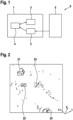
- Figure 1 shows a block diagram of a driver assistance system 6 comprising a device 1 for detecting and tracking objects in a surrounding of a vehicle.
- the device 1 comprises an interface 2 which communicates with one or more vehicle sensors 5 of the vehicle.
- the vehicle sensors may comprise at least one radar sensor.
- the vehicle sensors 5 can also comprise sensors like cameras, lidar sensors, infrared sensors and the like.
- the interface 2 may communicate with the vehicle sensors 5 via a CAN bus or the like.
- the device 1 receives via the interface 2 new measurement data from the vehicle sensor 5. That is, after each measurement cycle (time stamp), new measurement data is provided to the device 1.
- the device 1 may receive raw data from the radar sensor 5. According to other embodiments, the data may already be preprocessed.
- the device 1 comprises a computing device 4, such as a microprocessor, microcontroller, a field-programmable gate array, or the like.
- the computing device 4 determines time coordinates and spatial coordinates of newly identified candidate objects in a surrounding of the vehicle based on the newly acquired measurement data.
- the term "newly identified candidate object” relates to a particular measurement (i.e., within a present measurement cycle) of an object.
- the candidate object can be a candidate object (or real object) already tracked by the device 1 or a new object.
- the spatial coordinates of the newly identified candidate objects are defined relative to a global coordinate system, which may be given as a current pose of the vehicle, e.g., based on a current velocity of the vehicle.
- the computing device 4 associates each newly identified candidate object with one or none tracked candidate object of a plurality of tracked candidate objects. At each time, multiple objects may be tracked, e.g., corresponding to further vehicles, barriers, road signs, pedestrians and so on.
- the computing device 4 associates newly identified candidate objects with a tracked candidate object by computing for each tracked candidate object a distance between the newly identified candidate object and said tracked candidate object.
- the distance is computed based on both a difference between the spatial coordinates of the newly identified candidate object and the tracked candidate object and a difference between the time coordinates of the newly identified candidate object and the tracked candidate object.
- the distance can be computed using formula (1) above.
- the difference between the time coordinates of the newly identified candidate object and the tracked candidate object corresponds to the time difference between two subsequent measurements.
- the computing device 4 further updates the spatial coordinates of the tracked candidate objects using a Kalman filtering method.
- the computing device 4 may comprise a tracking pool for gathering the available Kalman filter instances, i.e., every tracked candidate object has one corresponding instance.
- the device 1 further comprises a first-in first-out, FIFO, memory device 3 which stores the time coordinates and spatial coordinates corresponding to several previously measured objects. Tracking means monitoring one stream that contains subsequent frames in which the detected objects are located. For the space-time representation, multiple past frames can be kept. If these frames are in the same global coordinate system, linear patterns can be captured. Further, the memory device 3 may store the global coordinate system.
- FIFO first-in first-out
- the computing device 4 detects at least one tracked real object of the tracked candidate objects based on a time behavior of the spatial coordinates of the candidate objects.
- real means that the object moves like an actual physical object and is therefore be identified as a real (physical) object.
- the computing device 4 may identify a tracked candidate object as a real object if the time behavior of the spatial coordinates of the candidate object corresponds to a straight line in the space-time representation (coordinate system).
- the computing device 4 may further classify the at least one real object based on a time behavior of the spatial coordinates of the candidate objects. For example, the computing device 4 may classify the at least one real object as a stationary object, if the time behavior of the spatial coordinates of the candidate object corresponds to an essentially linear line parallel to a time axis. Further, the computing device 4 may classify the at least one real object as a moving object, if the time behavior of the spatial coordinates of the candidate object corresponds to an essentially linear line tilted with respect to the time axis.
- the computing device 4 may further compute a velocity of the real object based on a tiltness of the essentially linear line with respect to the time axis.
- the computing device 4 can compute an angle between the time axis and the essentially linear line. E.g, based upon entries in a look up table, the computing device 4 determines the velocity of the real object based on the angle.
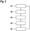
- Figure 2 shows a schematic illustration of tracked candidate objects.
- moving objects 21 and 22 and stationary objects 23 and 24.
- the stationary objects 23, 24 follow trajectories which are essentially parallel to the time coordinate t.
- Figure 3 shows a flow chart of a method for detecting and tracking objects in a surrounding of a vehicle. The method can be carried out using the device 1 described above. Likewise, the device 1 can be configured to carry out any of the following method steps or aspects of the method.
- tracking is initialized.
- a tracking pool is initialized which may have an instance count of 0.
- FIFO memory storage may be allocated. The size can be maximized, e.g., restricted to 5 frames.
- the current pose of the vehicle may be extracted and stored as a global coordinate system.
- the invention is not restricted to the vehicle coordinate system as a global coordinate system. According to other embodiments, different common global coordinate systems can be used.
- the memory storage may be relocated.
- the global coordinate system changes.
- the current ego vehicle is then again extracted as a global coordinate system.
- All tracked candidate objects from the tracking pool are transformed by transforming their spatial coordinates into the new global coordinate system.
- the new ego vehicle pose is stored as the global coordinate system.
- measurement initiates.
- the current ego vehicle speed is extracted.
- At least one vehicle sensor of the vehicle acquires measurement data.
- New measurement data is provided to the device 1 for tracking the objects.
- the device 1 may be located in the vehicle. At least some functions of the device 1 can also be located outside of the vehicle, e.g., in a distant server.
- the device 1 determines time coordinates and spatial coordinates (i.e., a measurement frame) of newly identified candidate objects in a surrounding of the vehicle based on the newly acquired measurement data.
- the time coordinates may simply be timestamps.
- the spatial coordinates of the newly identified candidate objects are defined relative to a global coordinate system.
- the spatial coordinates may first be defined in a non-global coordinate system and may then be transformed into the global coordinate system.
- the ego vehicle pose is tracked in the global coordinate system (i.e., common or "world” coordinate system) for each time instant where measurements are taken.
- a proper calibration may be required to be able to do affine transformation based coordination system changes between sensor coordinate systems, the space-time representation and the transformation into the global coordinate system.
- the device 1 associates each newly identified candidate object with at most one tracked candidate object of a plurality of tracked candidate objects based on distances between the newly identified candidate object and the plurality of tracked candidate objects.
- the distance depends on both a difference between the spatial coordinates of the newly identified candidate object and the tracked candidate object under consideration and a difference between the time coordinates of the newly identified candidate object and the tracked candidate object under consideration.
- the difference between the time coordinates can be set to 0 in the first iteration and can otherwise be set to the difference between a current timestamp and a stored timestamp.
- the transformed measurement frame ⁇ x, y, z, vt ⁇ is pushed into the memory storage 3.
- a fourth step S4 the spatial coordinates of the tracked candidate objects are updated, using a Kalman filtering method.
- the past information is used to stabilize the association step of the selected Kalman filter, by the movement derived from the state change of the continuously updated tracklet (tracked candidate object).
- Object detectors do have some noise arising from the measuring technique. Also, the tracking process can have ambiguity. These have to be modeled, a common choice is to use an additional normal distribution, and both have a dataset dependent hyperparameter (variance).
- the tracking is based on Kalman filtering.
- the state-transition model, the observation model, the measurement noise and the process noise are identical to the standard Kalman filtering method.
- the noises can be the above-mentioned normal distributions, e.g., with a variance of 0.01, and a constant state-transition model can be used.
- the current tracked state of the object is updated.
- the associated newly identified candidate object relates to new measurements taken into account in the Kalman method. If there is no match for some newly identified candidate object, a new tracked candidate object is generated. If none of the newly identified candidate objects is associated with one of the existing tracked candidate objects, the tracked candidate object is deleted.
- classification can be dynamic or stationary, depending on the tracked candidate object attributes available in Kalman filter inner states, e.g., momentum or speed.
- step S5 at least one tracked real object of the tracked candidate objects is detected based on a time behavior of the spatial coordinates of the candidate objects.
- the method may further comprise classifying the real objects (e.g. as stationary or moving objects).
- the method can then repeat again from step S1.
Landscapes
- Engineering & Computer Science (AREA)
- Radar, Positioning & Navigation (AREA)
- Remote Sensing (AREA)
- Physics & Mathematics (AREA)
- Computer Networks & Wireless Communication (AREA)
- General Physics & Mathematics (AREA)
- Electromagnetism (AREA)
- Image Analysis (AREA)
Abstract
Description
- The present invention relates to a method and a device for detecting and tracking objects in a surrounding of a vehicle. The invention further relates to a driver assistance system.
- Driver assistance systems rely on the detection of objects in a surrounding of the vehicle. Modern vehicles can comprise multiple sensors of different types, such as radar sensors, cameras, infrared sensors, lidar sensors and the like.
- Based on the sensor data, objects can be identified. For example, a radar sensor can emit radar signals which are reflected by objects in a surrounding of the vehicle. The coordinates of the reflecting objects can be determined by analyzing the received radar signals. Each of the recognized objects can be tracked over time. For example, the moving directions or velocities of the tracked candidate objects can be determined. Such information is important to estimate the likelihoods of possible events, such as a possible collision with another vehicle. Based on this information, the driver assistance systems can inform the driver of possibly dangerous situations or can control functions of the vehicle, such as an adjustment of the speed or the steering angle of the vehicle.
- For tracking objects, newly detected measurements must be associated with already tracked candidate objects, if possible. Tracking solutions are taking care of the association problem between objects detected in a subsequent frame by creating dynamic entities with a predefined lifespan. Although there are various solutions, due to the computation resource limitations, usually modeling assumptions have to be introduced. Filtering techniques (like Kalman filtering) can give a procedure-skeleton to such assumptions, in which the main steps are the following: prediction of the state of the observed objects for the next timestamp, the association between the predicted state of the object and the measurement at the next timestamp, and an update of the state of the observed object for further tracking.
- Implementation of radar detection systems may comprise rule-based filtering. Reliable locations may be identified as object candidates which are fed into a decision tree process to gain multi-layer probabilities. Bayesian classification methods can stabilize the output probabilities.
- An exemplary tracking method is known from
EP 1 557 693 B1 which can make use of a mean square deviation of curves. - The present invention provides a method and a device for classifying and tracking objects in a surrounding of a vehicle, and a driver assistance system, as recited in the independent claims.
- Preferred embodiments are set out in the dependent claims.
- According to a first aspect, the invention therefore relates to a device for detecting and tracking objects in a surrounding of a vehicle. An interface is configured to receive, from at least one vehicle sensor of the vehicle, new measurement data acquired at a current measurement cycle. A computing device is configured to determine time coordinates and spatial coordinates of newly identified candidate objects in a surrounding of the vehicle based on the new measurement data, wherein the spatial coordinates of the newly identified candidate objects are defined relative to a global coordinate system. The computing device further associates each newly identified candidate object with at most one tracked candidate object of a plurality of tracked candidate objects identified at earlier measurement cycles, based on distances between the newly identified candidate object and the tracked candidate objects of the plurality of tracked candidate objects. The distance depends on both a difference between the spatial coordinates of the newly identified candidate object and the tracked candidate object and a difference between the time coordinates of the newly identified candidate object and the tracked candidate object. The computing device is configured to update spatial coordinates of the tracked candidate objects using a Kalman filtering method, using the associated newly identified candidate objects. The computing device is further configured to detect at least one tracked real object of the tracked candidate objects based on a time behavior of the spatial coordinates of the candidate objects.
- According to a second aspect, the invention provides a driver assistance system for a vehicle, comprising at least one vehicle sensor of the vehicle configured to acquire measurement data, and a device for detecting and tracking objects in a surrounding of a vehicle according to the first aspect of the invention.
- According to a third aspect, the invention relates to a method for detecting and tracking objects in a surrounding of a vehicle. New measurement data acquired at a current measurement cycle are received from at least one vehicle sensor of the vehicle. Time coordinates and spatial coordinates of newly identified candidate objects in a surrounding of the vehicle are determined based on the new measurement data. The spatial coordinates of the newly identified candidate objects are defined relative to a global coordinate system. Each newly identified candidate object is associated with at most one tracked candidate object of a plurality of tracked candidate objects identified at earlier measurement cycles, based on distances between the newly identified candidate object and the plurality of tracked candidate objects. The distance depends on both a difference between the spatial coordinates of the newly identified candidate object and the tracked candidate object and a difference between the time coordinates of the newly identified candidate object and the tracked candidate object. Spatial coordinates of the tracked candidate objects are updated using a Kalman filtering method, using the associated newly identified candidate objects. At least one tracked real object of the tracked candidate objects is detected based on a time behavior of the spatial coordinates of the candidate objects.
- The present invention applies a space-time input representation and a modification to the association step. By using a distance which depends both on spatial coordinates and time coordinates, tracking is more robust to object movement. An improved object detector performance can be achieved. The tracking can be achieved in a space-time representation, where the distance metric is applied. The invention allows to detect objects based on the time behavior of the spatial coordinates of the candidate objects. For example, if a candidate object is found which follows a trajectory to be expected from a physical object, e.g. a straight line, the candidate object can be identified as a real object. The space-time representation allows to identify such straight movements, i.e. movement-dependent linear patterns.
- When the ego vehicle's movement is properly tracked by transforming the object detectors' frames (i.e., coordinates) taken at different time instants into a common coordinate system, and a proper multi-dimensional representation is chosen (2D/3D Cartesian coordinates and a time-like attribute), movement-dependent linear patterns can be formed for each object. Also, if these patterns are detected, their speed and momentum can be calculated to stabilize the classification itself.
- According to a further embodiment of the device, the computing device is configured to identify a candidate object as a real object if the time behavior of the spatial coordinates of the candidate object corresponds to an essentially linear (straight) line. By using a space-time representation in the global coordinate system, real objects follow (at least on not too long timescales) straight lines and can therefore be identified based on the time behavior of the spatial coordinates of candidate objects.
- According to a further embodiment of the device, the computing device is configured to classify the at least one real object based on a time behavior of the spatial coordinates of the candidate objects. Herein, classifying can comprise classifying the at least one real object as a moving object or a stationary object. The method combines object detection and a classification process where past information is used to stabilize the detection objective, and the classification is supported by the movement derived from the changing state of the continuously updated tracklet. When the ego vehicle's movement is properly tracked, by transforming the radar frames taken at different measurements into the common coordinate system and a proper 3D representation is chosen (e.g. planar radar coordinates and a time-like attribute), movement-dependent linear patterns are formed per object.
- According to a further embodiment of the device, the computing device is configured to classify the at least one real object as a stationary object, if the time behavior of the spatial coordinates of the candidate object corresponds to an essentially linear line parallel to a time axis. In a global coordinate system, stationary objects follow straight (linear) lines along the time axis. According to some embodiments, the at least one real object is identified as a stationary object if the time behavior of the spatial coordinates forms a line which includes an angle with the time axis which is smaller than a predefined threshold value.
- According to a further embodiment of the device, the computing device is configured to classify the at least one real object as a moving object, if the time behavior of the spatial coordinates of the candidate object corresponds to an essentially linear line tilted with respect to a time axis. According to some embodiments, the at least one real object is identified as a moving object if the time behavior of the spatial coordinates forms a line which includes an angle with the time axis which is greater than a predefined threshold value.
- According to a further embodiment of the device, the computing device is configured to compute a velocity of the real object based on an angle of the essentially linear line with respect to the time axis. In some embodiments, an angle between a line defined by the spatial coordinates of the real object at different time points and the time axis is computed. The velocity is computed based on the angle. In the space-time representation, each angle is uniquely related to a corresponding velocity.
- According to a further embodiment of the device, the distance D (i.e. metric) between a newly identified candidate object and a tracked candidate object is computed by the following formula:

- According to a further embodiment of the device, the computing device is configured to determine the global coordinate system as a current pose of the vehicle, based on a current velocity of the vehicle. After each measurement cycle, the global coordinate system can be recomputed.
- According to a further embodiment of the device, the computing device is configured to associate the newly identified candidate object with the at most one tracked candidate object using the Hungarian method. Herein, the above metric defined in formula (1) can be used instead of a conventional Euclidean metric.
- According to a further embodiment, the device further comprises a first-in first-out, FIFO, memory device, wherein the computing device is configured to store the time coordinates and spatial coordinates of newly identified candidate objects in the FIFO memory device. For an efficient space-time representation, multiple past frames (i.e., time coordinates and spatial coordinates) can be kept.
- According to a further embodiment of the device, the computing device is further configured to transform spatial coordinates of the plurality of tracked candidate objects into the global coordinate system before associating each newly identified candidate object with at most one tracked candidate object of the plurality of tracked candidate objects. Therefore, the newly identified candidate objects can easily be associated with the tracked candidate object.
- According to a further embodiment of the device, the computing device is further configured to generate a new tracked candidate object based on a newly identified candidate object if said newly identified candidate object is not associated with any tracked candidate object of the plurality of tracked candidate objects. Therefore, the list of tracked candidate objects can be extended.
- According to a further embodiment of the device, the computing device is further configured to delete a tracked candidate object of the plurality of tracked candidate objects if no newly identified candidate object is associated with the tracked candidate object. Therefore, objects no longer present in the field of view of the at least one vehicle sensor can be deleted. Such objects are generally no longer relevant for driver assistance systems or the like.
-
- Figure 1
- shows a block diagram of a driver assistance system comprising a device for detecting and tracking objects in a surrounding of a vehicle according to an embodiment of the invention;
- Figure 2
- shows a schematic illustration of tracked candidate objects; and
- Figure 3
- shows a flow chart of a method for detecting and tracking objects in a surrounding of a vehicle according to an embodiment of the invention.
- The numbering of process steps is for clarity and is generally not intended to imply any particular chronological order. In particular, several process steps can also be carried out simultaneously.
-
Figure 1 shows a block diagram of a driver assistance system 6 comprising a device 1 for detecting and tracking objects in a surrounding of a vehicle. The device 1 comprises aninterface 2 which communicates with one ormore vehicle sensors 5 of the vehicle. Preferably, the vehicle sensors may comprise at least one radar sensor. Thevehicle sensors 5 can also comprise sensors like cameras, lidar sensors, infrared sensors and the like. - The
interface 2 may communicate with thevehicle sensors 5 via a CAN bus or the like. The device 1 receives via theinterface 2 new measurement data from thevehicle sensor 5. That is, after each measurement cycle (time stamp), new measurement data is provided to the device 1. The device 1 may receive raw data from theradar sensor 5. According to other embodiments, the data may already be preprocessed. - The device 1 comprises a
computing device 4, such as a microprocessor, microcontroller, a field-programmable gate array, or the like. Thecomputing device 4 determines time coordinates and spatial coordinates of newly identified candidate objects in a surrounding of the vehicle based on the newly acquired measurement data. Herein, the term "newly identified candidate object" relates to a particular measurement (i.e., within a present measurement cycle) of an object. The candidate object can be a candidate object (or real object) already tracked by the device 1 or a new object. - The spatial coordinates of the newly identified candidate objects are defined relative to a global coordinate system, which may be given as a current pose of the vehicle, e.g., based on a current velocity of the vehicle.
- The
computing device 4 associates each newly identified candidate object with one or none tracked candidate object of a plurality of tracked candidate objects. At each time, multiple objects may be tracked, e.g., corresponding to further vehicles, barriers, road signs, pedestrians and so on. - The
computing device 4 associates newly identified candidate objects with a tracked candidate object by computing for each tracked candidate object a distance between the newly identified candidate object and said tracked candidate object. The distance is computed based on both a difference between the spatial coordinates of the newly identified candidate object and the tracked candidate object and a difference between the time coordinates of the newly identified candidate object and the tracked candidate object. For example, the distance can be computed using formula (1) above. In general, the difference between the time coordinates of the newly identified candidate object and the tracked candidate object corresponds to the time difference between two subsequent measurements. - The
computing device 4 further updates the spatial coordinates of the tracked candidate objects using a Kalman filtering method. - The
computing device 4 may comprise a tracking pool for gathering the available Kalman filter instances, i.e., every tracked candidate object has one corresponding instance. - The device 1 further comprises a first-in first-out, FIFO,
memory device 3 which stores the time coordinates and spatial coordinates corresponding to several previously measured objects. Tracking means monitoring one stream that contains subsequent frames in which the detected objects are located. For the space-time representation, multiple past frames can be kept. If these frames are in the same global coordinate system, linear patterns can be captured. Further, thememory device 3 may store the global coordinate system. - The
computing device 4 detects at least one tracked real object of the tracked candidate objects based on a time behavior of the spatial coordinates of the candidate objects. Herein "real" means that the object moves like an actual physical object and is therefore be identified as a real (physical) object. - The
computing device 4 may identify a tracked candidate object as a real object if the time behavior of the spatial coordinates of the candidate object corresponds to a straight line in the space-time representation (coordinate system). Thecomputing device 4 may further classify the at least one real object based on a time behavior of the spatial coordinates of the candidate objects. For example, thecomputing device 4 may classify the at least one real object as a stationary object, if the time behavior of the spatial coordinates of the candidate object corresponds to an essentially linear line parallel to a time axis. Further, thecomputing device 4 may classify the at least one real object as a moving object, if the time behavior of the spatial coordinates of the candidate object corresponds to an essentially linear line tilted with respect to the time axis. - The
computing device 4 may further compute a velocity of the real object based on a tiltness of the essentially linear line with respect to the time axis. Thecomputing device 4 can compute an angle between the time axis and the essentially linear line. E.g, based upon entries in a look up table, thecomputing device 4 determines the velocity of the real object based on the angle. -
Figure 2 shows a schematic illustration of tracked candidate objects. There are movingobjects stationary objects stationary objects -
Figure 3 shows a flow chart of a method for detecting and tracking objects in a surrounding of a vehicle. The method can be carried out using the device 1 described above. Likewise, the device 1 can be configured to carry out any of the following method steps or aspects of the method. - In a step S1, tracking is initialized. Further, a tracking pool is initialized which may have an instance count of 0. Further, FIFO memory storage may be allocated. The size can be maximized, e.g., restricted to 5 frames. The current pose of the vehicle may be extracted and stored as a global coordinate system. However, the invention is not restricted to the vehicle coordinate system as a global coordinate system. According to other embodiments, different common global coordinate systems can be used. The memory storage may be relocated.
- After a drift occurs in ego vehicle positioning, the global coordinate system changes. The current ego vehicle is then again extracted as a global coordinate system. All tracked candidate objects from the tracking pool are transformed by transforming their spatial coordinates into the new global coordinate system. The new ego vehicle pose is stored as the global coordinate system.
- Next, measurement initiates. The current ego vehicle speed is extracted. At least one vehicle sensor of the vehicle acquires measurement data. New measurement data is provided to the device 1 for tracking the objects. The device 1 may be located in the vehicle. At least some functions of the device 1 can also be located outside of the vehicle, e.g., in a distant server.
- In a second step S2, the device 1 determines time coordinates and spatial coordinates (i.e., a measurement frame) of newly identified candidate objects in a surrounding of the vehicle based on the newly acquired measurement data. The time coordinates may simply be timestamps. The spatial coordinates of the newly identified candidate objects are defined relative to a global coordinate system. The spatial coordinates may first be defined in a non-global coordinate system and may then be transformed into the global coordinate system.
- Together with the measurement data, the ego vehicle pose is tracked in the global coordinate system (i.e., common or "world" coordinate system) for each time instant where measurements are taken.
- Moreover, a proper calibration may be required to be able to do affine transformation based coordination system changes between sensor coordinate systems, the space-time representation and the transformation into the global coordinate system.
- In a step S3, the device 1 associates each newly identified candidate object with at most one tracked candidate object of a plurality of tracked candidate objects based on distances between the newly identified candidate object and the plurality of tracked candidate objects. The distance depends on both a difference between the spatial coordinates of the newly identified candidate object and the tracked candidate object under consideration and a difference between the time coordinates of the newly identified candidate object and the tracked candidate object under consideration.
- The difference between the time coordinates can be set to 0 in the first iteration and can otherwise be set to the difference between a current timestamp and a stored timestamp.
- It can also be possible to store a 4-dimensional vector {x, y, z, vt} associated with each newly acquired object, comprising the spatial coordinates x, y, z and a parameter

memory storage 3. - In a fourth step S4, the spatial coordinates of the tracked candidate objects are updated, using a Kalman filtering method. In space-time tracking, the past information is used to stabilize the association step of the selected Kalman filter, by the movement derived from the state change of the continuously updated tracklet (tracked candidate object).
- Object detectors do have some noise arising from the measuring technique. Also, the tracking process can have ambiguity. These have to be modeled, a common choice is to use an additional normal distribution, and both have a dataset dependent hyperparameter (variance). The tracking is based on Kalman filtering. Herein, the state-transition model, the observation model, the measurement noise and the process noise are identical to the standard Kalman filtering method. The noises can be the above-mentioned normal distributions, e.g., with a variance of 0.01, and a constant state-transition model can be used.
- In the Kalman-update step, the current tracked state of the object is updated. Herein, the associated newly identified candidate object relates to new measurements taken into account in the Kalman method. If there is no match for some newly identified candidate object, a new tracked candidate object is generated. If none of the newly identified candidate objects is associated with one of the existing tracked candidate objects, the tracked candidate object is deleted.
- Optionally, for currently available tracked candidate objects, further classification can be applied. The classification can be dynamic or stationary, depending on the tracked candidate object attributes available in Kalman filter inner states, e.g., momentum or speed.
- In step S5, at least one tracked real object of the tracked candidate objects is detected based on a time behavior of the spatial coordinates of the candidate objects. The method may further comprise classifying the real objects (e.g. as stationary or moving objects).
- The method can then repeat again from step S1.
Claims (10)
- A device (1) for detecting and tracking objects in a surrounding of a vehicle, comprising:an interface (2) configured to receive, from at least one vehicle sensor (5) of the vehicle, new measurement data acquired at a current measurement cycle; anda computing device (4) configured to:determine time coordinates and spatial coordinates of newly identified candidate objects in a surrounding of the vehicle based on the new measurement data, wherein the spatial coordinates of the newly identified candidate objects are defined relative to a global coordinate system;associate each newly identified candidate object with at most one tracked candidate object (21-24) of a plurality of tracked candidate objects (21-24) identified at earlier measurement cycles, based on distances between the newly identified candidate object and the plurality of tracked candidate objects (21-24), wherein the distance depends on both a difference between the spatial coordinates of the newly identified candidate object and the tracked candidate object and a difference between the time coordinates of the newly identified candidate object and the tracked candidate object;update spatial coordinates of the tracked candidate objects (21-24) using a Kalman filtering method, using the associated newly identified candidate objects; anddetect at least one tracked real object of the tracked candidate objects based on a time behavior of the spatial coordinates of the candidate objects (21-24).
- The device (1) according to claim 1, wherein the computing device (4) is configured to identify a candidate objects as a real object if the time behavior of the spatial coordinates of the candidate object (21-24) corresponds to an essentially linear line.
- The device (1) according to claim 1 or 2, wherein the computing device (4) is configured to classify the at least one real object based on a time behavior of the spatial coordinates of the candidate objects (21-24).
- The device (1) according to claim 3, wherein the computing device (4) is configured to classify the at least one real object as a stationary object, if the time behavior of the spatial coordinates of the candidate object (21-24) corresponds to an essentially linear line parallel to a time axis.
- The device (1) according to claim 3 or 4, wherein the computing device (4) is configured to classify the at least one real object as a moving object, if the time behavior of the spatial coordinates of the candidate object (21-24) corresponds to an essentially linear line tilted with respect to a time axis.
- The device (1) according to claim 5, wherein the computing device (4) is configured to compute a velocity of the real object based on an angle of the essentially linear line with respect to the time axis.
- The device (1) according to claim 1, wherein the distance D between a newly identified candidate object and a tracked candidate object (21-24) is computed by the following formula:

- The device (1) according to any of the preceding claims, wherein the computing device (4) is further configured to generate a new tracked candidate object (21-24) if a newly identified candidate object is not associated with a tracked candidate object (21-24) of the plurality of tracked candidate objects (21-24).
- A driver assistance system (6) for a vehicle, comprisingat least one vehicle sensor (5) of the vehicle, configured to acquire measurement data; anda device (1) for detecting and tracking objects in a surrounding of a vehicle according to any of the preceding claims.
- A method for detecting and tracking objects in a surrounding of a vehicle, comprising the following steps:receiving (S1), from at least one vehicle sensor (5) of the vehicle, new measurement data acquired at a current measurement cycle;determining (S2) time coordinates and spatial coordinates of newly identified candidate objects in a surrounding of the vehicle based on the new measurement data, wherein the spatial coordinates of the newly identified candidate objects are defined relative to a global coordinate system;associating (S3) each newly identified candidate object with at most one tracked candidate object (21-24) of a plurality of tracked candidate objects (21-24) identified at earlier measurement cycles, based on distances between the newly identified candidate object and the plurality of tracked candidate objects (21-24), wherein the distance depends on both a difference between the spatial coordinates of the newly identified candidate object and the tracked candidate object and a difference between the time coordinates of the newly identified candidate object and the tracked candidate object;updating (S4) spatial coordinates of the tracked candidate objects (21-24) using a Kalman filtering method, using the associated newly identified candidate objects; anddetecting (S5) at least one tracked real object of the tracked candidate objects based on a time behavior of the spatial coordinates of the candidate objects (21-24).
Priority Applications (1)
| Application Number | Priority Date | Filing Date | Title |
|---|---|---|---|
| EP22153358.1A EP4220224B1 (en) | 2022-01-26 | 2022-01-26 | Method and device for detecting and tracking objects and driver assistance system |
Applications Claiming Priority (1)
| Application Number | Priority Date | Filing Date | Title |
|---|---|---|---|
| EP22153358.1A EP4220224B1 (en) | 2022-01-26 | 2022-01-26 | Method and device for detecting and tracking objects and driver assistance system |
Publications (2)
| Publication Number | Publication Date |
|---|---|
| EP4220224A1 true EP4220224A1 (en) | 2023-08-02 |
| EP4220224B1 EP4220224B1 (en) | 2025-05-21 |
Family
ID=80034916
Family Applications (1)
| Application Number | Title | Priority Date | Filing Date |
|---|---|---|---|
| EP22153358.1A Active EP4220224B1 (en) | 2022-01-26 | 2022-01-26 | Method and device for detecting and tracking objects and driver assistance system |
Country Status (1)
| Country | Link |
|---|---|
| EP (1) | EP4220224B1 (en) |
Citations (4)
| Publication number | Priority date | Publication date | Assignee | Title |
|---|---|---|---|---|
| EP1557693B1 (en) | 2004-01-26 | 2009-05-20 | IBEO Automobile Sensor GmbH | Method for tracking objects |
| US20150198711A1 (en) * | 2014-01-16 | 2015-07-16 | GM Global Technology Operations LLC | Object fusion system of multiple radar imaging sensors |
| US20160018219A1 (en) * | 2013-03-04 | 2016-01-21 | Denso Corporation | Estimation apparatus |
| US20210080558A1 (en) * | 2019-09-13 | 2021-03-18 | Aptiv Technologies Limited | Extended Object Tracking Using RADAR |
-
2022
- 2022-01-26 EP EP22153358.1A patent/EP4220224B1/en active Active
Patent Citations (4)
| Publication number | Priority date | Publication date | Assignee | Title |
|---|---|---|---|---|
| EP1557693B1 (en) | 2004-01-26 | 2009-05-20 | IBEO Automobile Sensor GmbH | Method for tracking objects |
| US20160018219A1 (en) * | 2013-03-04 | 2016-01-21 | Denso Corporation | Estimation apparatus |
| US20150198711A1 (en) * | 2014-01-16 | 2015-07-16 | GM Global Technology Operations LLC | Object fusion system of multiple radar imaging sensors |
| US20210080558A1 (en) * | 2019-09-13 | 2021-03-18 | Aptiv Technologies Limited | Extended Object Tracking Using RADAR |
Also Published As
| Publication number | Publication date |
|---|---|
| EP4220224B1 (en) | 2025-05-21 |
Similar Documents
| Publication | Publication Date | Title |
|---|---|---|
| CN109564285A (en) | Method and system for detecting ground marks in a traffic environment of a mobile unit | |
| KR102168288B1 (en) | System and method for tracking multiple object using multi-LiDAR | |
| JP7056842B2 (en) | State estimator and program | |
| CN114002667A (en) | Multi-neighbor extended target tracking algorithm based on random matrix method | |
| CN115856872A (en) | Vehicle motion track continuous tracking method | |
| CN112036422B (en) | A track management method, system and computer-readable medium based on multi-sensor information fusion | |
| CN114119465B (en) | Point cloud data processing method and device | |
| CN118850119B (en) | Environment perception system based on intelligent driving | |
| EP3467545A1 (en) | Object classification | |
| CN109407086B (en) | Aircraft trajectory generation method and system and trapping system target guiding method | |
| CN115512542B (en) | A track restoration method and system based on roadside lidar considering occlusion | |
| EP4220224B1 (en) | Method and device for detecting and tracking objects and driver assistance system | |
| CN120913409A (en) | Highway monitoring method for radar and video fusion dynamic space-time alignment | |
| CN120612345A (en) | A target fusion tracking method, device, and computer program product | |
| EP4174520B1 (en) | Method and device for tracking objects and driver assistance system | |
| EP4246183A1 (en) | Method and device for segmenting radar data | |
| US20230408686A1 (en) | Method and apparatus for detecting static object by means of radar sensor of roadside unit | |
| JP7052404B2 (en) | State estimator and program | |
| Stellet et al. | Post processing of laser scanner measurements for testing advanced driver assistance systems | |
| JP6903955B2 (en) | Moving object state quantity estimation device and program | |
| CN117606500A (en) | Deceleration strip detection method, deceleration strip passing method, network training method and related device | |
| EP4220217A1 (en) | Method and device for segmenting radar data, and driver assistance system | |
| Domhof et al. | Multi-sensor object tracking performance limits by the cramer-rao lower bound | |
| EP3805987B1 (en) | Annotating a sparsely sampled data set | |
| Kim et al. | Multitarget tracking with lidar and stereo vision based on probabilistic data association fir filter |
Legal Events
| Date | Code | Title | Description |
|---|---|---|---|
| PUAI | Public reference made under article 153(3) epc to a published international application that has entered the european phase |
Free format text: ORIGINAL CODE: 0009012 |
|
| STAA | Information on the status of an ep patent application or granted ep patent |
Free format text: STATUS: THE APPLICATION HAS BEEN PUBLISHED |
|
| AK | Designated contracting states |
Kind code of ref document: A1 Designated state(s): AL AT BE BG CH CY CZ DE DK EE ES FI FR GB GR HR HU IE IS IT LI LT LU LV MC MK MT NL NO PL PT RO RS SE SI SK SM TR |
|
| STAA | Information on the status of an ep patent application or granted ep patent |
Free format text: STATUS: REQUEST FOR EXAMINATION WAS MADE |
|
| 17P | Request for examination filed |
Effective date: 20240202 |
|
| RBV | Designated contracting states (corrected) |
Designated state(s): AL AT BE BG CH CY CZ DE DK EE ES FI FR GB GR HR HU IE IS IT LI LT LU LV MC MK MT NL NO PL PT RO RS SE SI SK SM TR |
|
| GRAP | Despatch of communication of intention to grant a patent |
Free format text: ORIGINAL CODE: EPIDOSNIGR1 |
|
| STAA | Information on the status of an ep patent application or granted ep patent |
Free format text: STATUS: GRANT OF PATENT IS INTENDED |
|
| RIC1 | Information provided on ipc code assigned before grant |
Ipc: G01S 13/86 20060101ALN20250225BHEP Ipc: G01S 13/58 20060101ALN20250225BHEP Ipc: G01S 7/295 20060101ALI20250225BHEP Ipc: G01S 17/931 20200101ALI20250225BHEP Ipc: G01S 17/86 20200101ALI20250225BHEP Ipc: G01S 17/66 20060101ALI20250225BHEP Ipc: G01S 13/931 20200101ALI20250225BHEP Ipc: G01S 13/72 20060101AFI20250225BHEP |
|
| GRAS | Grant fee paid |
Free format text: ORIGINAL CODE: EPIDOSNIGR3 |
|
| INTG | Intention to grant announced |
Effective date: 20250314 |
|
| GRAA | (expected) grant |
Free format text: ORIGINAL CODE: 0009210 |
|
| STAA | Information on the status of an ep patent application or granted ep patent |
Free format text: STATUS: THE PATENT HAS BEEN GRANTED |
|
| AK | Designated contracting states |
Kind code of ref document: B1 Designated state(s): AL AT BE BG CH CY CZ DE DK EE ES FI FR GB GR HR HU IE IS IT LI LT LU LV MC MK MT NL NO PL PT RO RS SE SI SK SM TR |
|
| REG | Reference to a national code |
Ref country code: GB Ref legal event code: FG4D |
|
| REG | Reference to a national code |
Ref country code: CH Ref legal event code: EP |
|
| REG | Reference to a national code |
Ref country code: DE Ref legal event code: R096 Ref document number: 602022014805 Country of ref document: DE |
|
| REG | Reference to a national code |
Ref country code: IE Ref legal event code: FG4D |
|
| REG | Reference to a national code |
Ref country code: NL Ref legal event code: MP Effective date: 20250521 |
|
| PG25 | Lapsed in a contracting state [announced via postgrant information from national office to epo] |
Ref country code: PT Free format text: LAPSE BECAUSE OF FAILURE TO SUBMIT A TRANSLATION OF THE DESCRIPTION OR TO PAY THE FEE WITHIN THE PRESCRIBED TIME-LIMIT Effective date: 20250922 Ref country code: FI Free format text: LAPSE BECAUSE OF FAILURE TO SUBMIT A TRANSLATION OF THE DESCRIPTION OR TO PAY THE FEE WITHIN THE PRESCRIBED TIME-LIMIT Effective date: 20250521 Ref country code: ES Free format text: LAPSE BECAUSE OF FAILURE TO SUBMIT A TRANSLATION OF THE DESCRIPTION OR TO PAY THE FEE WITHIN THE PRESCRIBED TIME-LIMIT Effective date: 20250521 |
|
| REG | Reference to a national code |
Ref country code: LT Ref legal event code: MG9D |
|
| PG25 | Lapsed in a contracting state [announced via postgrant information from national office to epo] |
Ref country code: GR Free format text: LAPSE BECAUSE OF FAILURE TO SUBMIT A TRANSLATION OF THE DESCRIPTION OR TO PAY THE FEE WITHIN THE PRESCRIBED TIME-LIMIT Effective date: 20250822 Ref country code: NO Free format text: LAPSE BECAUSE OF FAILURE TO SUBMIT A TRANSLATION OF THE DESCRIPTION OR TO PAY THE FEE WITHIN THE PRESCRIBED TIME-LIMIT Effective date: 20250821 |
|
| PG25 | Lapsed in a contracting state [announced via postgrant information from national office to epo] |
Ref country code: NL Free format text: LAPSE BECAUSE OF FAILURE TO SUBMIT A TRANSLATION OF THE DESCRIPTION OR TO PAY THE FEE WITHIN THE PRESCRIBED TIME-LIMIT Effective date: 20250521 Ref country code: PL Free format text: LAPSE BECAUSE OF FAILURE TO SUBMIT A TRANSLATION OF THE DESCRIPTION OR TO PAY THE FEE WITHIN THE PRESCRIBED TIME-LIMIT Effective date: 20250521 |
|
| PG25 | Lapsed in a contracting state [announced via postgrant information from national office to epo] |
Ref country code: BG Free format text: LAPSE BECAUSE OF FAILURE TO SUBMIT A TRANSLATION OF THE DESCRIPTION OR TO PAY THE FEE WITHIN THE PRESCRIBED TIME-LIMIT Effective date: 20250521 |
|
| PG25 | Lapsed in a contracting state [announced via postgrant information from national office to epo] |
Ref country code: HR Free format text: LAPSE BECAUSE OF FAILURE TO SUBMIT A TRANSLATION OF THE DESCRIPTION OR TO PAY THE FEE WITHIN THE PRESCRIBED TIME-LIMIT Effective date: 20250521 |
|
| PG25 | Lapsed in a contracting state [announced via postgrant information from national office to epo] |
Ref country code: RS Free format text: LAPSE BECAUSE OF FAILURE TO SUBMIT A TRANSLATION OF THE DESCRIPTION OR TO PAY THE FEE WITHIN THE PRESCRIBED TIME-LIMIT Effective date: 20250821 |
|
| PG25 | Lapsed in a contracting state [announced via postgrant information from national office to epo] |
Ref country code: IS Free format text: LAPSE BECAUSE OF FAILURE TO SUBMIT A TRANSLATION OF THE DESCRIPTION OR TO PAY THE FEE WITHIN THE PRESCRIBED TIME-LIMIT Effective date: 20250921 |
|
| PG25 | Lapsed in a contracting state [announced via postgrant information from national office to epo] |
Ref country code: LV Free format text: LAPSE BECAUSE OF FAILURE TO SUBMIT A TRANSLATION OF THE DESCRIPTION OR TO PAY THE FEE WITHIN THE PRESCRIBED TIME-LIMIT Effective date: 20250521 |
|
| REG | Reference to a national code |
Ref country code: AT Ref legal event code: MK05 Ref document number: 1797203 Country of ref document: AT Kind code of ref document: T Effective date: 20250521 |
|
| PG25 | Lapsed in a contracting state [announced via postgrant information from national office to epo] |
Ref country code: AT Free format text: LAPSE BECAUSE OF FAILURE TO SUBMIT A TRANSLATION OF THE DESCRIPTION OR TO PAY THE FEE WITHIN THE PRESCRIBED TIME-LIMIT Effective date: 20250521 Ref country code: SM Free format text: LAPSE BECAUSE OF FAILURE TO SUBMIT A TRANSLATION OF THE DESCRIPTION OR TO PAY THE FEE WITHIN THE PRESCRIBED TIME-LIMIT Effective date: 20250521 Ref country code: DK Free format text: LAPSE BECAUSE OF FAILURE TO SUBMIT A TRANSLATION OF THE DESCRIPTION OR TO PAY THE FEE WITHIN THE PRESCRIBED TIME-LIMIT Effective date: 20250521 |
|
| PG25 | Lapsed in a contracting state [announced via postgrant information from national office to epo] |
Ref country code: CZ Free format text: LAPSE BECAUSE OF FAILURE TO SUBMIT A TRANSLATION OF THE DESCRIPTION OR TO PAY THE FEE WITHIN THE PRESCRIBED TIME-LIMIT Effective date: 20250521 |
|
| PG25 | Lapsed in a contracting state [announced via postgrant information from national office to epo] |
Ref country code: EE Free format text: LAPSE BECAUSE OF FAILURE TO SUBMIT A TRANSLATION OF THE DESCRIPTION OR TO PAY THE FEE WITHIN THE PRESCRIBED TIME-LIMIT Effective date: 20250521 |
|
| PG25 | Lapsed in a contracting state [announced via postgrant information from national office to epo] |
Ref country code: SK Free format text: LAPSE BECAUSE OF FAILURE TO SUBMIT A TRANSLATION OF THE DESCRIPTION OR TO PAY THE FEE WITHIN THE PRESCRIBED TIME-LIMIT Effective date: 20250521 |
|
| PG25 | Lapsed in a contracting state [announced via postgrant information from national office to epo] |
Ref country code: IT Free format text: LAPSE BECAUSE OF FAILURE TO SUBMIT A TRANSLATION OF THE DESCRIPTION OR TO PAY THE FEE WITHIN THE PRESCRIBED TIME-LIMIT Effective date: 20250521 |
|
| REG | Reference to a national code |
Ref country code: DE Ref legal event code: R097 Ref document number: 602022014805 Country of ref document: DE |
|
| PLBE | No opposition filed within time limit |
Free format text: ORIGINAL CODE: 0009261 |
|
| STAA | Information on the status of an ep patent application or granted ep patent |
Free format text: STATUS: NO OPPOSITION FILED WITHIN TIME LIMIT |
|
| REG | Reference to a national code |
Ref country code: CH Ref legal event code: L10 Free format text: ST27 STATUS EVENT CODE: U-0-0-L10-L00 (AS PROVIDED BY THE NATIONAL OFFICE) Effective date: 20260402 |
|
| PGFP | Annual fee paid to national office [announced via postgrant information from national office to epo] |
Ref country code: GB Payment date: 20260122 Year of fee payment: 5 |
|
| PGFP | Annual fee paid to national office [announced via postgrant information from national office to epo] |
Ref country code: DE Payment date: 20260319 Year of fee payment: 5 |
|
| PGFP | Annual fee paid to national office [announced via postgrant information from national office to epo] |
Ref country code: FR Payment date: 20260128 Year of fee payment: 5 |
|
| 26N | No opposition filed |
Effective date: 20260224 |