EP4220185A1 - Inspection chip - Google Patents
Inspection chip Download PDFInfo
- Publication number
- EP4220185A1 EP4220185A1 EP21872249.4A EP21872249A EP4220185A1 EP 4220185 A1 EP4220185 A1 EP 4220185A1 EP 21872249 A EP21872249 A EP 21872249A EP 4220185 A1 EP4220185 A1 EP 4220185A1
- Authority
- EP
- European Patent Office
- Prior art keywords
- channel
- state
- rotary valve
- adsorption
- inspection chip
- Prior art date
- Legal status (The legal status is an assumption and is not a legal conclusion. Google has not performed a legal analysis and makes no representation as to the accuracy of the status listed.)
- Pending
Links
Images






Classifications
-
- G—PHYSICS
- G01—MEASURING; TESTING
- G01N—INVESTIGATING OR ANALYSING MATERIALS BY DETERMINING THEIR CHEMICAL OR PHYSICAL PROPERTIES
- G01N30/00—Investigating or analysing materials by separation into components using adsorption, absorption or similar phenomena or using ion-exchange, e.g. chromatography or field flow fractionation
- G01N30/02—Column chromatography
- G01N30/26—Conditioning of the fluid carrier; Flow patterns
-
- B—PERFORMING OPERATIONS; TRANSPORTING
- B01—PHYSICAL OR CHEMICAL PROCESSES OR APPARATUS IN GENERAL
- B01L—CHEMICAL OR PHYSICAL LABORATORY APPARATUS FOR GENERAL USE
- B01L3/00—Containers or dishes for laboratory use, e.g. laboratory glassware; Droppers
- B01L3/50—Containers for the purpose of retaining a material to be analysed, e.g. test tubes
- B01L3/502—Containers for the purpose of retaining a material to be analysed, e.g. test tubes with fluid transport, e.g. in multi-compartment structures
- B01L3/5027—Containers for the purpose of retaining a material to be analysed, e.g. test tubes with fluid transport, e.g. in multi-compartment structures by integrated microfluidic structures, i.e. dimensions of channels and chambers are such that surface tension forces are important, e.g. lab-on-a-chip
- B01L3/502738—Containers for the purpose of retaining a material to be analysed, e.g. test tubes with fluid transport, e.g. in multi-compartment structures by integrated microfluidic structures, i.e. dimensions of channels and chambers are such that surface tension forces are important, e.g. lab-on-a-chip characterised by integrated valves
-
- G—PHYSICS
- G01—MEASURING; TESTING
- G01N—INVESTIGATING OR ANALYSING MATERIALS BY DETERMINING THEIR CHEMICAL OR PHYSICAL PROPERTIES
- G01N35/00—Automatic analysis not limited to methods or materials provided for in any single one of groups G01N1/00 - G01N33/00; Handling materials therefor
- G01N35/08—Automatic analysis not limited to methods or materials provided for in any single one of groups G01N1/00 - G01N33/00; Handling materials therefor using a stream of discrete samples flowing along a tube system, e.g. flow injection analysis
-
- B—PERFORMING OPERATIONS; TRANSPORTING
- B01—PHYSICAL OR CHEMICAL PROCESSES OR APPARATUS IN GENERAL
- B01L—CHEMICAL OR PHYSICAL LABORATORY APPARATUS FOR GENERAL USE
- B01L2200/00—Solutions for specific problems relating to chemical or physical laboratory apparatus
- B01L2200/06—Fluid handling related problems
- B01L2200/0684—Venting, avoiding backpressure, avoid gas bubbles
-
- B—PERFORMING OPERATIONS; TRANSPORTING
- B01—PHYSICAL OR CHEMICAL PROCESSES OR APPARATUS IN GENERAL
- B01L—CHEMICAL OR PHYSICAL LABORATORY APPARATUS FOR GENERAL USE
- B01L2200/00—Solutions for specific problems relating to chemical or physical laboratory apparatus
- B01L2200/06—Fluid handling related problems
- B01L2200/0689—Sealing
-
- B—PERFORMING OPERATIONS; TRANSPORTING
- B01—PHYSICAL OR CHEMICAL PROCESSES OR APPARATUS IN GENERAL
- B01L—CHEMICAL OR PHYSICAL LABORATORY APPARATUS FOR GENERAL USE
- B01L2200/00—Solutions for specific problems relating to chemical or physical laboratory apparatus
- B01L2200/14—Process control and prevention of errors
- B01L2200/141—Preventing contamination, tampering
-
- B—PERFORMING OPERATIONS; TRANSPORTING
- B01—PHYSICAL OR CHEMICAL PROCESSES OR APPARATUS IN GENERAL
- B01L—CHEMICAL OR PHYSICAL LABORATORY APPARATUS FOR GENERAL USE
- B01L2300/00—Additional constructional details
- B01L2300/06—Auxiliary integrated devices, integrated components
- B01L2300/0681—Filter
-
- B—PERFORMING OPERATIONS; TRANSPORTING
- B01—PHYSICAL OR CHEMICAL PROCESSES OR APPARATUS IN GENERAL
- B01L—CHEMICAL OR PHYSICAL LABORATORY APPARATUS FOR GENERAL USE
- B01L2300/00—Additional constructional details
- B01L2300/08—Geometry, shape and general structure
- B01L2300/0861—Configuration of multiple channels and/or chambers in a single devices
- B01L2300/0864—Configuration of multiple channels and/or chambers in a single devices comprising only one inlet and multiple receiving wells, e.g. for separation, splitting
-
- B—PERFORMING OPERATIONS; TRANSPORTING
- B01—PHYSICAL OR CHEMICAL PROCESSES OR APPARATUS IN GENERAL
- B01L—CHEMICAL OR PHYSICAL LABORATORY APPARATUS FOR GENERAL USE
- B01L2300/00—Additional constructional details
- B01L2300/08—Geometry, shape and general structure
- B01L2300/0861—Configuration of multiple channels and/or chambers in a single devices
- B01L2300/0867—Multiple inlets and one sample wells, e.g. mixing, dilution
-
- B—PERFORMING OPERATIONS; TRANSPORTING
- B01—PHYSICAL OR CHEMICAL PROCESSES OR APPARATUS IN GENERAL
- B01L—CHEMICAL OR PHYSICAL LABORATORY APPARATUS FOR GENERAL USE
- B01L2300/00—Additional constructional details
- B01L2300/08—Geometry, shape and general structure
- B01L2300/0861—Configuration of multiple channels and/or chambers in a single devices
- B01L2300/0874—Three dimensional network
-
- B—PERFORMING OPERATIONS; TRANSPORTING
- B01—PHYSICAL OR CHEMICAL PROCESSES OR APPARATUS IN GENERAL
- B01L—CHEMICAL OR PHYSICAL LABORATORY APPARATUS FOR GENERAL USE
- B01L2300/00—Additional constructional details
- B01L2300/08—Geometry, shape and general structure
- B01L2300/0887—Laminated structure
-
- B—PERFORMING OPERATIONS; TRANSPORTING
- B01—PHYSICAL OR CHEMICAL PROCESSES OR APPARATUS IN GENERAL
- B01L—CHEMICAL OR PHYSICAL LABORATORY APPARATUS FOR GENERAL USE
- B01L2300/00—Additional constructional details
- B01L2300/16—Surface properties and coatings
- B01L2300/161—Control and use of surface tension forces, e.g. hydrophobic, hydrophilic
- B01L2300/165—Specific details about hydrophobic, oleophobic surfaces
-
- B—PERFORMING OPERATIONS; TRANSPORTING
- B01—PHYSICAL OR CHEMICAL PROCESSES OR APPARATUS IN GENERAL
- B01L—CHEMICAL OR PHYSICAL LABORATORY APPARATUS FOR GENERAL USE
- B01L2400/00—Moving or stopping fluids
- B01L2400/04—Moving fluids with specific forces or mechanical means
- B01L2400/0403—Moving fluids with specific forces or mechanical means specific forces
- B01L2400/0442—Moving fluids with specific forces or mechanical means specific forces thermal energy, e.g. vaporisation, bubble jet
-
- B—PERFORMING OPERATIONS; TRANSPORTING
- B01—PHYSICAL OR CHEMICAL PROCESSES OR APPARATUS IN GENERAL
- B01L—CHEMICAL OR PHYSICAL LABORATORY APPARATUS FOR GENERAL USE
- B01L2400/00—Moving or stopping fluids
- B01L2400/06—Valves, specific forms thereof
- B01L2400/0622—Valves, specific forms thereof distribution valves, valves having multiple inlets and/or outlets, e.g. metering valves, multi-way valves
-
- B—PERFORMING OPERATIONS; TRANSPORTING
- B01—PHYSICAL OR CHEMICAL PROCESSES OR APPARATUS IN GENERAL
- B01L—CHEMICAL OR PHYSICAL LABORATORY APPARATUS FOR GENERAL USE
- B01L2400/00—Moving or stopping fluids
- B01L2400/06—Valves, specific forms thereof
- B01L2400/0633—Valves, specific forms thereof with moving parts
- B01L2400/0644—Valves, specific forms thereof with moving parts rotary valves
-
- B—PERFORMING OPERATIONS; TRANSPORTING
- B01—PHYSICAL OR CHEMICAL PROCESSES OR APPARATUS IN GENERAL
- B01L—CHEMICAL OR PHYSICAL LABORATORY APPARATUS FOR GENERAL USE
- B01L3/00—Containers or dishes for laboratory use, e.g. laboratory glassware; Droppers
- B01L3/50—Containers for the purpose of retaining a material to be analysed, e.g. test tubes
- B01L3/502—Containers for the purpose of retaining a material to be analysed, e.g. test tubes with fluid transport, e.g. in multi-compartment structures
- B01L3/5027—Containers for the purpose of retaining a material to be analysed, e.g. test tubes with fluid transport, e.g. in multi-compartment structures by integrated microfluidic structures, i.e. dimensions of channels and chambers are such that surface tension forces are important, e.g. lab-on-a-chip
- B01L3/50273—Containers for the purpose of retaining a material to be analysed, e.g. test tubes with fluid transport, e.g. in multi-compartment structures by integrated microfluidic structures, i.e. dimensions of channels and chambers are such that surface tension forces are important, e.g. lab-on-a-chip characterised by the means or forces applied to move the fluids
Definitions
- the present invention relates to an inspection chip provided with a channel switching structure.
- Patent Document 1 discloses an inspection chip in which a fine channel is provided in a plate-shaped base material.
- the plate-shaped base material is provided with a through hole connected to the fine channel.
- External channel means movable on an outer surface of the plate-shaped base material is provided.
- the external channel means has a channel. By moving the external channel means on the surface of the base material, a connection state between the channel of the external channel means and the through hole is changed. The channel is thus switched.
- Patent Document 1 JP 2005-214741 A
- An object of the present invention is to provide an inspection chip with simplified channel switching structure, which is generally complicated.
- An inspection chip includes a chip main body having a specimen introduction channel, an adsorption channel including an adsorption unit, a first waste liquid channel, a recovery liquid introduction channel, and a detection channel including a detection unit; and a rotary valve attached to the chip main body so as to be rotatable about a rotation axis, the rotary valve having a plurality of connection channels, the plurality of connection channels being arranged so that the rotary valve is capable of taking at least a first state and a second state when the rotary valve rotates about the rotation axis, the first state being a state in which the specimen introduction channel, the adsorption channel, and the first waste liquid channel are connected so as to be provided in this order from an upstream side, and the second state being a state in which the recovery liquid introduction channel, the adsorption channel, and the detection channel are connected so as to be provided in this order from the upstream side.
- one of the plurality of connection channels connects a downstream end of the adsorption channel and an upstream end of the detection channel.
- the chip main body further has a mixing channel; and in the second state, the recovery liquid introduction channel, the adsorption channel, the mixing channel, and the detection channel are connected so as to be provided in this order from the upstream side.
- the chip main body further has a second waste liquid channel; and in the second state, the recovery liquid introduction channel, the adsorption channel, the detection channel, and the second waste liquid channel are connected so as to be provided in this order from the upstream side.
- the chip main body further has a vent channel; and in the second state, the recovery liquid introduction channel, the adsorption channel, the detection channel, the second waste liquid channel, and the vent channel are connected so as to be provided in this order from the upstream side.
- the chip main body further has a washing liquid introduction channel; and the plurality of connection channels is arranged so that the rotary valve is capable of taking at least the first state, the second state, and a third state when the rotary valve rotates about the rotation axis, the third state being a state in which the washing liquid introduction channel, the adsorption channel, and the first waste liquid channel are connected so as to be provided in this order from the upstream side.
- the plurality of connection channels is arranged so that the rotary valve is capable of taking the first state, the third state, and the second state in this order when the rotary valve rotates about the rotation axis.
- the plurality of connection channels is arranged so that the rotary valve is capable of further taking a fourth state after the second state when the rotary valve rotates about the rotation axis, the fourth state being a state in which an upstream end and a downstream end of the detection channel are sealed.
- the plurality of connection channels is arranged so that the rotary valve is capable of further taking a fifth state after the second state when the rotary valve rotates about the rotation axis, the fifth state being a state in which an upstream end and a downstream end of the detection channel are sealed and an upstream end and a downstream end of the second waste liquid channel are sealed.
- the adsorption channel is provided at a position where the adsorption channel overlaps the rotary valve in plan view.
- a hydrophobic filter is connected to a downstream end of at least one of the first waste liquid channel and the second waste liquid channel.
- the inspection chip further includes an optical gas generation tape that generates gas upon irradiation of light, and liquid feeding is performed by the gas generated from the optical gas generation tape.
- Fig. 1 is a schematic perspective view illustrating an appearance of an inspection chip according to a first embodiment of the present invention.
- Fig. 2 is a schematic cross-sectional view of a portion taken along line A-A in Fig. 1 .
- the inspection chip 1 includes a chip main body 2 and a rotary valve 3.
- the chip main body 2 may have any shape, but has a rectangular plate shape.
- the chip main body 2 has a first surface 2a and a second surface 2b opposite to the first surface 2a.
- the rotary valve 3 is attached to the chip main body 2 so as to be rotatable about a central axis which is a rotation axis.
- the chip main body 2 includes a substrate 4 and a sealing sheet 5 laminated on the substrate 4.
- the substrate 4 is made of an appropriate material such as a synthetic resin.
- a surface of the substrate 4 opposite to the sealing sheet 5 is the first surface 2a of the chip main body 2.
- An outer surface of the sealing sheet 5 is the second surface 2b of the chip main body 2.
- the sealing sheet 5 is made of an appropriate sheet such as a synthetic resin sheet.
- a first channel 6, a second channel 7, and a third channel 8 are provided in the substrate 4.
- the first channel 6, the second channel 7, and the third channel 8 are opened in the first surface 2a.
- the first channel 6, the second channel 7, and the third channel 8 extend so as to connect the first surface 2a and the second surface 2b.
- a groove provided on the lower surface of the substrate 4 is sealed, and thus an adsorption unit 9 is provided.
- An adsorbent 9A is accommodated in the adsorption unit 9.
- the adsorption unit 9 is connected between the first channel 6 and the second channel 7.
- the adsorption unit 9, the first channel 6, and the second channel 7 constitute an adsorption channel 11.
- the rotary valve 3 is attached to the substrate 4 so as to be rotatable about a rotation axis B which is a central axis.
- the first channel 6 is provided so as to include the rotation axis B.
- the central axis of the first channel 6 coincides with the rotation axis B.
- a groove provided on the lower surface of the substrate 4 is sealed, and thus a fourth channel 10 is provided.
- the fourth channel 10 is connected to an end portion of the third channel 8 on a side opposite to an end portion thereof opened in the first surface 2a of the chip main body 2.
- the fourth channel 10 extends away from the rotation axis B in a radial direction of the rotary valve 3.
- the third channel 8 and the fourth channel 10 constitute a specimen introduction channel, a recovery liquid introduction channel, or a washing liquid introduction channel.
- the fourth channel 10 is provided on a same straight line as the adsorption unit 9 in Fig.
- the fourth channel 10 constituting the specimen introduction channel, the recovery liquid introduction channel, or the washing liquid introduction channel is not provided on the same straight line as the adsorption unit 9 in the present embodiment. Note, however, that the fourth channel 10 may be provided on the same straight line as the adsorption unit 9.
- Fig. 3 is a schematic plan view for explaining channels in a rotary valve in the inspection chip according to the first embodiment of the present invention.
- a first connection channel 12 and a plurality of second connection channels 13 to 15 are provided on a lower surface 3a of the rotary valve 3.
- the first connection channel 12 and the second connection channels 13 to 15 are provided by providing a groove having a shape like the one illustrated in Fig. 3 on the lower surface 3a of the rotary valve 3.
- the groove is sealed by the first surface 2a of the chip main body 2, and thus the first connection channel 12 and the second connection channel 13 are formed.
- the second connection channel 13 is illustrated in Fig. 2 , the other second connection channels 14 and 15 are similarly configured.
- one end of the first connection channel 12 reaches a portion where the rotation axis B exists, and is connected to the first channel 6.
- the first connection channel 12 extends outward in the radial direction of the rotary valve 3 from the rotation axis B of the rotary valve 3.
- the first connection channel 12 may have another planar shape such as a curved shape, a meander shape, or an L shape. Therefore, the first connection channel 12 is not limited to extending from the rotation axis B to the outside in the radial direction of the rotary valve 3, and needs to just extend from the rotation axis B to the outside.
- a radially outer end portion of the first connection channel 12 is connected to the third channel 8 in Fig. 2 . However, by rotating the rotary valve 3 about the rotation axis B, the radially outer end portion of the first connection channel 12 can also be connected to other channels.
- the second connection channel 13 is provided at a position separated from the first connection channel 12 and separated from the rotation axis B. In the state illustrated in Fig. 2 , the second connection channel 13 is connected to the second channel 7. By rotating the rotary valve 3 about the rotation axis B, the second channel 7 can be connected to other second connection channels 14 and 15 in the rotary valve 3. Alternatively, instead of the second connection channel 13, other second connection channels 14 and 15 can be connected to a channel such as the second channel 7 in the chip main body 2.
- Fig. 4 is a schematic perspective view for explaining channels provided in the chip main body in the inspection chip according to the first embodiment of the present invention.
- the rotary valve 3 On the first surface 2a side of the chip main body 2, the rotary valve 3 is attached at a position indicated by an alternate long and short dash line C.
- one end of the first channel 6, one end of the second channel 7, and one end of the third channel 8 are opened in the first surface 2a.
- the first channel 6, the second channel 7, and the third channel 8 extend from the first surface 2a toward the second surface 2b of the chip main body 2.
- the adsorption unit 9 is connected between the first channel 6 and the second channel 7.
- the end portion of the third channel 8 on the side opposite to the side opened in the first surface 2a is connected to the fourth channel 10.
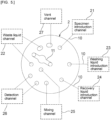
- a specimen introduction channel 21, a waste liquid channel 22, a washing liquid introduction channel 23, a recovery liquid introduction channel 24, a mixing channel 25, a detection channel 26, and a vent channel 27 illustrated in Fig. 5 are provided in the chip main body 2.
- a plurality of the fourth channels 10 described above is provided in the chip main body 2, and the fourth channels 10 constitute the specimen introduction channel 21, the washing liquid introduction channel 23, and the recovery liquid introduction channel 24.
- the fourth channels 10 may be connected to the specimen introduction channel 21, the washing liquid introduction channel 23, and the recovery liquid introduction channel 24.
- the first connection channel 12 can be connected to the specimen introduction channel 21, the washing liquid introduction channel 23, and the recovery liquid introduction channel 24.
- the second connection channels 13 to 15 can be connected to the waste liquid channel 22 and the mixing channel 25.
- a plurality of connection channels is arranged so that at least a first state and a second state described below can be taken when the rotary valve 3 is rotated about the rotation axis B.
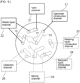
- the first state is a state in which the specimen introduction channel 21, the adsorption channel 11, and the waste liquid channel 22 are connected in this order from an upstream side.
- the specimen introduction channel 21 and the adsorption channel 11 are connected by the first connection channel 12.
- the adsorption channel 11 and the waste liquid channel 22 are connected by the second connection channel 13.
- the second state is a state in which the recovery liquid introduction channel 24, the adsorption channel 11, and the detection channel 26 are connected in this order from the upstream side.
- the recovery liquid introduction channel 24 and the adsorption channel 11 are connected by the first connection channel 12.
- the mixing channel 25 is provided between the adsorption channel 11 and the detection channel 26, and the adsorption channel 11 and the mixing channel 25 are connected by the second connection channel 15.
- the waste liquid channel 22 is connected to a downstream side of the detection channel 26.
- the vent channel 27 is connected to a downstream side of the waste liquid channel 22. Note, however, that the mixing channel 25 and the vent channel 27 need not necessarily be provided.
- the waste liquid channel 22 need not necessarily be connected to the downstream side of the detection channel 26.
- a nucleic acid extracted from a specimen by using an extraction liquid can be adsorbed to the adsorbent 9A, recovered, and subjected to a test such as PCR (Polymerase Chain Reaction) in the inspection chip 1.
- PCR Polymerase Chain Reaction
- the inspection chip 1 of the present embodiment can be also applied to various reaction tests and inspections requiring same or similar liquid feeding step by using suitable adsorbent and detection method.
- the rotary valve 3 is configured to be rotated about the rotation axis B so as to be able to take at least the first state and the second state.
- the rotary valve 3 may be configured to take a third state, a fourth state, and the like in addition to the first state and the second state.
- the rotary valve 3 may be configured to perform a third state of flowing a washing liquid between the first state of flowing a specimen and the second state of flowing a recovery liquid.
- the rotary valve 3 may be configured to perform a fourth state in which at least an upstream end and a downstream end of the detection channel 26 are sealed.
- the one first connection channel 12 and the three second connection channels 13 to 15 constitute a plurality of connection channels.
- a plurality of first connection channels may be provided.
- the number of first connection channels can be, for example, 1 or more and 3 or less.
- the number of second connection channels can be, for example, 1 or more and 10 or less.
- the total number of connection channels can be, for example, 2 or more and 13 or less.
- Fig. 6 is a schematic plan view for explaining a channel connection state in the first state of the inspection chip according to the first embodiment of the present invention.
- the rotary valve 3 is rotated to connect the specimen introduction channel 21, the adsorption channel 11, and the waste liquid channel 22 in this order as illustrated in Fig. 6 .
- the specimen introduction channel 21 and the adsorption channel 11 are connected by the first connection channel 12.
- the adsorption channel 11 and the waste liquid channel 22 are connected by the second connection channel 13.
- the vent channel 27 is connected to the downstream side of the waste liquid channel 22.
- a specimen can be supplied to the adsorption channel 11 by introducing the specimen from the specimen introduction channel 21. Then, a waste liquid reaches the waste liquid channel 22 and is discharged. Examples of the specimen include body fluids, viruses, bacteria, cells, and extracts thereof.
- the adsorption channel 11 has the adsorption unit 9 illustrated in Fig. 2 , and the adsorbent 9A for adsorbing, for example, a nucleic acid extracted from the specimen by using an extraction liquid is accommodated in the adsorption unit 9.
- FIG. 7 is a schematic plan view for explaining a channel connection state in the third state of the inspection chip according to the first embodiment of the present invention.
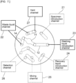
- the washing liquid introduction channel 23, the adsorption channel 11, and the waste liquid channel 22 are connected in this order.
- the washing liquid introduction channel 23 and the adsorption channel 11 are connected by the first connection channel 12.
- the adsorption channel 11 and the waste liquid channel 22 are connected by the second connection channel 14.
- the vent channel 27 is connected to the downstream side of the waste liquid channel 22.
- a washing liquid can be supplied to the adsorption channel 11 by introducing the washing liquid from the washing liquid introduction channel 23. Then, a waste liquid reaches the waste liquid channel 22 and is discharged. The nucleic acid adsorbed on the adsorbent 9A can be washed with the washing liquid supplied to the adsorption channel 11.
- Fig. 8 is a schematic plan view for explaining a channel connection state in the second state of the inspection chip according to the first embodiment of the present invention.
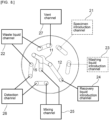
- the recovery liquid introduction channel 24, the adsorption channel 11, and the detection channel 26 are connected in this order.
- the recovery liquid introduction channel 24 and the adsorption channel 11 are connected by the first connection channel 12.
- the adsorption channel 11 and the detection channel 26 are connected by the second connection channel 15.
- a recovery liquid can be supplied to the adsorption channel 11 by introducing the recovery liquid from the recovery liquid introduction channel 24.
- the recovery liquid for example, the nucleic acid adsorbed on the adsorbent 9A can be recovered, and the recovered nucleic acid can be supplied to the detection channel 26.
- a waste liquid reaches the waste liquid channel 22 and is discharged.
- the detection channel 26 has a detection unit, and can perform a reaction such as PCR by using the supplied nucleic acid or the like.
- the recovery liquid for example, water can be used.
- the mixing channel 25 is provided between the second connection channel 15 and the detection channel 26.
- a recovery liquid containing the nucleic acid and a reaction reagent to be fed later can be merged and mixed. Thereafter, the mixed liquid is supplied to the detection channel 26, and thereby a test can be performed.
- the reaction reagent for example, a PCR reaction reagent can be used.
- the waste liquid channel 22 is connected to the downstream side of the detection channel 26. Furthermore, the vent channel 27 is connected to the downstream side of the waste liquid channel 22.
- the channel in the inspection chip 1 can be switched so that the first state and the second state can be taken. Therefore, introduction, washing, recovery, reaction, and the like of a specimen can be performed with a relatively simple structure.
- a recovery rate of the nucleic acid can be further increased by switching the channel in the inspection chip 1 so that the third state can be taken between the first state and the second state and performing cleaning.
- FIG. 9 is a schematic plan view for explaining a channel connection state in the fourth state of the inspection chip according to the first embodiment of the present invention.
- the upstream end and the downstream end of the detection channel 26, the upstream end and the downstream end of the mixing channel 25, and the upstream end and the downstream end of the waste liquid channel 22 are sealed.
- the upstream end and the downstream end of the detection channel 26 can be sealed. In this case, outflow of a reaction product to an outside can be further suppressed. Furthermore, by sealing the upstream end and the downstream end of the mixing channel 25, contamination can be further suppressed. Furthermore, when the vent channel 27 is provided as in the present embodiment, the upstream end and the downstream end of the waste liquid channel 22 can be sealed. In this case, outflow of the waste liquid to the outside can be suppressed with more certainty.
- dimensions of the channels are not particularly limited, but are preferably micro channels.
- the micro channels as used herein refer to fine channels in which a micro effect is generated when a fluid is conveyed. In such a micro channel, the fluid is strongly affected by surface tension, and exhibits behavior different from that of a fluid flowing through a channel having a typical large size.
- Cross-sectional shape and size of the micro channel are not particularly limited as long as the micro channel is a channel in which the micro effect is generated.
- a dimension of a shorter side of the micro channel is preferably 20 pm or more, more preferably 50 um or more, still more preferably 100 um or more from the viewpoint of further reducing channel resistance when the cross-sectional shape of the micro channel is substantially rectangular (including square).
- the dimension is preferably 5 mm or less, more preferably 1 mm or less, still more preferably 500 um or less.
- a diameter is preferably 20 um or more, more preferably 50 um or more, still more preferably 100 um or more. From the viewpoint of further reducing the size of the microfluidic device, the diameter (a minor axis in a case of an ellipse) is preferably 5 mm or less, more preferably 1 mm or less, still more preferably 500 pm or less.
- the dimension of the shorter side of the micro channel is preferably 5 pm or more, more preferably 10 um or more, still more preferably 20 pm or more when the cross-sectional shape of the micro channel is substantially rectangular (including square). Furthermore, the dimension of the shorter side is preferably 200 um or less, and more preferably 100 um or less.
- An appropriate liquid feeder can be used to feed the specimen, the washing liquid, or the recovery liquid.
- an optical gas generation tape that generates gas upon irradiation of light.
- Fig. 10 is a schematic cross-sectional view for explaining a liquid feeding method using the optical gas generation tape.
- the fourth channel 10 constituting the specimen introduction channel 21, the washing liquid introduction channel 23, and the recovery liquid introduction channel 24 is opened in the first surface 2a.
- An optical gas generation tape 31 is attached to the first surface 2a so as to seal this opened portion. Accordingly, the optical gas generation tape 31 is disposed on an upstream side relative to the fourth channel 10 constituting the specimen introduction channel 21, the washing liquid introduction channel 23, and the recovery liquid introduction channel 24.
- the optical gas generation tape 31 generates gas upon irradiation of light.
- the specimen, the washing liquid, or the recovery liquid can be fed by the gas thus generated.
- the adsorbent 9A is accommodated in the adsorption unit 9 in the adsorption channel 11 illustrated in Fig. 2 .
- the adsorbent 9A can be, for example, used in a form such as a membrane form, a filter form, a plate form, a fibrous form, a tube form, a particle form, or a porous form.
- the adsorbent 9A can be, for example, made of a silicon compound, a phosphate mineral, a silicate mineral, an aluminosilicate mineral, or the like.
- the adsorbent 9A is preferably silica fiber or glass fiber.
- the mixing channel 25 is not particularly limited, but for example, a first mixing channel illustrated in Fig. 11 can be used.
- the first mixing channel 32 is, for example, a channel for merging and mixing a recovery liquid containing nucleic acid and a reaction reagent to be fed later.
- the first mixing channel 32 has a zigzag structure in plan view. Furthermore, in the first mixing channel 32, a depth of the channel is increased in the hatched portions. Specifically, in the first mixing channel 32, a first channel portion 32a having a relatively deep channel and a second channel portion 32b having a relatively shallow channel are repeatedly and alternately provided.
- the first channel portion 32a extends in a first direction Xl, is bent at a first bent portion 32c, and is continuous with the second channel portion 32b.
- the second channel portion 32b extends in a second direction X2, is bent at a second bent portion 32d, and is continuous with the first channel portion 32a.
- the first bent portion 32c and the second bent portion 32d are bent portions that not only bend the channel but also change the depth of the channel.
- the first mixing channel 32 having a zigzag structure in plan view and having a repeated height difference is configured.
- a second mixing channel illustrated in Fig. 12 may be used.
- a second mixing channel 33 has a first channel portion 33a and a second channel portion 33b.
- the first channel portion 33a is a recessed portion in which the channel is enlarged toward one side surface of the inspection chip 1.
- the second channel portion 33b is a recessed portion in which the channel is enlarged toward the other side surface of the inspection chip 1.
- the first channel portion 33a and the second channel portion 33b are alternately provided in order, starting with the first channel portion 33a.
- first mixing channel 32 or the second mixing channel 33 may be used alone or the first mixing channel 32 and the second mixing channel 33 may be used in combination.
- the detection channel 26 is a channel having a detection unit that performs PCR or the like.
- Fig. 13 is a schematic plan view illustrating a channel structure as an example of a detection channel.
- the detection channel 41 has a main channel 42.
- One end of each of a plurality of branch channels 43 to 45 is connected to the main channel 42.
- the branch channels 43 to 45 are provided as, for example, reaction tanks for performing a reaction such as PCR.
- Channel resistance portions 46 to 48 having cross-sectional areas smaller than those of the branch channels 43 to 45 are provided at end portions of the branch channels 43 to 45 on a side opposite to the side connected to the main channel 42.
- the one end of each of the branch channels 43 to 45 is an inflow end and is open to the main channel 42.
- the other end of each of the branch channels 43 to 45 is an outflow end and is connected to corresponding one of the channel resistance portions 46 to 48.
- connection channel 49 Downstream ends of the channel resistance portions 46 to 48 are connected to a connection channel 49.
- the connection channel 49 is connected to the main channel 42.
- a sub branch channel 50 is connected to the main channel 42. Also between the adjacent branch channels 44 and 45, a sub branch channel 51 is connected to the main channel 42.
- the sub branch channels 50 and 51 have inflow ends connected to the main channel 42, but the sub branch channels 50 and 51 do not have an outlet for gas. The inflow ends of the sub branch channels 50 and 51 are open to the main channel 42.
- the sub branch channel 50 By providing the sub branch channel 50, contamination of a specimen and a reagent between the branch channels 43 and 44 can be suppressed.
- the sub branch channel 51 can also suppress contamination between the adjacent branch channels 44 and 45.
- a hydrophobic filter may be provided at the downstream end of the waste liquid channel.
- the hydrophobic filter for example, a polytetrafluoroethylene (PTFE) filter or the like can be used.
- PTFE polytetrafluoroethylene
- Examples of a commercially available hydrophobic filter include PF-020, PF-040, PF-050, and PF-060 (all manufactured by ADVANTEC CO., LTD.).
- Fig. 14 is a schematic plan view for explaining channels in a rotary valve in an inspection chip according to a second embodiment of the present invention.
- Fig. 15 is a schematic plan view for explaining channels in a chip main body in the inspection chip according to the second embodiment of the present invention.
- a first connection channel 72 and a plurality of second connection channels 73 to 75 are provided on a lower surface 63a of a rotary valve 63.
- the first connection channel 72 and the second connection channels 73 to 75 are configured in a similar manner to the first embodiment on the lower surface 63a of the rotary valve 63.
- a specimen introduction channel 81, a first waste liquid channel 82a, a washing liquid introduction channel 83, a recovery liquid introduction channel 84, a detection channel 86, and a second waste liquid channel 82b are provided in a chip main body 62.
- the first connection channel 72 can be connected to the specimen introduction channel 81, the washing liquid introduction channel 83, and the recovery liquid introduction channel 84.
- the second connection channels 73 to 75 can be connected to the first waste liquid channel 82a and the second waste liquid channel 82b and the detection channel 86.
- the plurality of connection channels is arranged so that at least a first state and a second state described below can be taken when the rotary valve 63 is rotated about the rotation axis.
- the first state is a state in which the specimen introduction channel 81, an adsorption channel 71, and the first waste liquid channel 82a are connected in this order from an upstream side.
- the specimen introduction channel 81 and the adsorption channel 71 are connected by the first connection channel 72.
- the adsorption channel 71 and the first waste liquid channel 82a are connected by the second connection channel 73.
- the second state is a state in which the recovery liquid introduction channel 84, the adsorption channel 71, and the detection channel 86 are connected in this order from the upstream side.
- the recovery liquid introduction channel 84 and the adsorption channel 71 are connected by the first connection channel 72.
- the adsorption channel 71 and the detection channel 86 are connected by the second connection channel 75.
- no mixing channel is provided between the second connection channel 75 and the detection channel 86.
- the second waste liquid channel 82b is connected to a downstream side of the detection channel 86. However, a vent channel is not connected to a downstream side of the second waste liquid channel 82b.
- a nucleic acid extracted from a specimen by using an extraction liquid can be adsorbed to an adsorbent, recovered, and subjected to a test such as PCR in the inspection chip according to the second embodiment.
- the rotary valve 63 is configured to be rotated about the rotation axis so as to be able to take at least the first state and the second state.
- the rotary valve 63 may be configured to take a third state, a fourth state, and the like in addition to the first state and the second state.
- the rotary valve 63 may be configured to perform a third state of flowing a washing liquid between the first state of flowing a specimen and the second state of flowing a recovery liquid.
- the rotary valve may be configured to perform a fourth state in which at least an upstream end and a downstream end of the detection channel 86 are sealed.
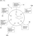
- Fig. 16 is a schematic plan view for explaining a channel connection state in the first state of the inspection chip according to the second embodiment of the present invention.
- the rotary valve 63 is rotated to connect the specimen introduction channel 81, the adsorption channel 71, and the first waste liquid channel 82a in this order as illustrated in Fig. 16 .
- the specimen introduction channel 81 and the adsorption channel 71 are connected by the first connection channel 72.
- the adsorption channel 71 and the first waste liquid channel 82a are connected by the second connection channel 73.
- a specimen can be supplied to the adsorption channel 71 by introducing the specimen from the specimen introduction channel 81. Then, the waste liquid reaches the first waste liquid channel 82a and is discharged.
- the adsorption channel 71 has an adsorption unit, and an adsorbent for adsorbing, for example, a nucleic acid extracted from the specimen by using an extraction liquid is accommodated in the adsorption unit.
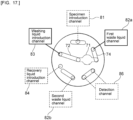
- FIG. 17 is a schematic plan view for explaining a channel connection state in the third state of the inspection chip according to the second embodiment of the present invention.
- the washing liquid introduction channel 83, the adsorption channel 71, and the first waste liquid channel 82a are connected in this order.
- the washing liquid introduction channel 83 and the adsorption channel 71 are connected by the first connection channel 72.
- the adsorption channel 71 and the first waste liquid channel 82a are connected by the second connection channel 74.
- a washing liquid can be supplied to the adsorption channel 71 by introducing the washing liquid from the washing liquid introduction channel 83. Then, the waste liquid reaches the first waste liquid channel 82a and is discharged. The nucleic acid adsorbed on the adsorbent can be washed with the washing liquid supplied to the adsorption channel 71.
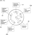
- Fig. 18 is a schematic plan view for explaining a channel connection state in the second state of the inspection chip according to the second embodiment of the present invention.
- the recovery liquid introduction channel 84, the adsorption channel 71, and the detection channel 86 is connected in this order.
- the recovery liquid introduction channel 84 and the adsorption channel 71 are connected by the first connection channel 72.
- the adsorption channel 71 and the detection channel 86 are connected by the second connection channel 75.
- the second waste liquid channel 82b is connected to a downstream side of the detection channel 86.
- a recovery liquid can be supplied to the adsorption channel 71 by introducing the recovery liquid from the recovery liquid introduction channel 84.
- the recovery liquid With the recovery liquid, the nucleic acid adsorbed on the adsorbent can be recovered, and the recovered nucleic acid can be supplied to the detection channel 86.
- the waste liquid reaches the second waste liquid channel 82b and is discharged.
- the detection channel 86 has a detection unit, and can perform a reaction such as PCR by using the supplied nucleic acid or the like.
- the channel in the inspection chip can be switched so that the first state and the second state can be taken. Therefore, introduction, washing, recovery, inspection, and the like of a specimen can be performed with a relatively simple structure.
- a recovery rate of the nucleic acid can be further increased by switching the channel in the inspection chip so that the third state can be taken between the first state and the second state and performing cleaning.
- FIG. 19 is a schematic plan view for explaining a channel connection state in the fourth state of the inspection chip according to the second embodiment of the present invention.
- the upstream end and the downstream end of the detection channel 86 are sealed.
- the upstream end and the downstream end of the detection channel 86 can be sealed. In this case, outflow of a reaction product to an outside can be further suppressed.
- the first waste liquid channel 82a used after feeding the specimen and the washing liquid and the second waste liquid channel 82b used after feeding the recovery liquid are separately provided.
- the first waste liquid channel 82a and the second waste liquid channel 82b may be the same waste liquid channel, as in the first embodiment.
Landscapes
- Chemical & Material Sciences (AREA)
- Health & Medical Sciences (AREA)
- General Health & Medical Sciences (AREA)
- Analytical Chemistry (AREA)
- Physics & Mathematics (AREA)
- Life Sciences & Earth Sciences (AREA)
- Biochemistry (AREA)
- General Physics & Mathematics (AREA)
- Immunology (AREA)
- Pathology (AREA)
- Hematology (AREA)
- Clinical Laboratory Science (AREA)
- Chemical Kinetics & Catalysis (AREA)
- Dispersion Chemistry (AREA)
- Automatic Analysis And Handling Materials Therefor (AREA)
- Multiple-Way Valves (AREA)
- Apparatus Associated With Microorganisms And Enzymes (AREA)
Abstract
Description
- The present invention relates to an inspection chip provided with a channel switching structure.
- Conventionally, tests such as blood tests and genetic tests have been attempted by controlling liquid feeding and reactions of various specimens or samples by using an inspection chip provided with a channel through which a fluid is delivered.
- For example,
Patent Document 1 below discloses an inspection chip in which a fine channel is provided in a plate-shaped base material. The plate-shaped base material is provided with a through hole connected to the fine channel. External channel means movable on an outer surface of the plate-shaped base material is provided. The external channel means has a channel. By moving the external channel means on the surface of the base material, a connection state between the channel of the external channel means and the through hole is changed. The channel is thus switched. - Patent Document 1:
JP 2005-214741 A - In an inspection chip like the one disclosed in
Patent Document 1, when analysis is performed by using a plurality of reagents or samples, switching of a channel becomes more complicated. - An object of the present invention is to provide an inspection chip with simplified channel switching structure, which is generally complicated.
- An inspection chip according to the present invention includes a chip main body having a specimen introduction channel, an adsorption channel including an adsorption unit, a first waste liquid channel, a recovery liquid introduction channel, and a detection channel including a detection unit; and a rotary valve attached to the chip main body so as to be rotatable about a rotation axis, the rotary valve having a plurality of connection channels, the plurality of connection channels being arranged so that the rotary valve is capable of taking at least a first state and a second state when the rotary valve rotates about the rotation axis, the first state being a state in which the specimen introduction channel, the adsorption channel, and the first waste liquid channel are connected so as to be provided in this order from an upstream side, and the second state being a state in which the recovery liquid introduction channel, the adsorption channel, and the detection channel are connected so as to be provided in this order from the upstream side.
- In a specific aspect of the inspection chip according to the present invention, in the second state, one of the plurality of connection channels connects a downstream end of the adsorption channel and an upstream end of the detection channel.
- In another specific aspect of the inspection chip according to the present invention, the chip main body further has a mixing channel; and in the second state, the recovery liquid introduction channel, the adsorption channel, the mixing channel, and the detection channel are connected so as to be provided in this order from the upstream side.
- In still another specific aspect of the inspection chip according to the present invention, the chip main body further has a second waste liquid channel; and in the second state, the recovery liquid introduction channel, the adsorption channel, the detection channel, and the second waste liquid channel are connected so as to be provided in this order from the upstream side.
- In still another specific aspect of the inspection chip according to the present invention, the chip main body further has a vent channel; and in the second state, the recovery liquid introduction channel, the adsorption channel, the detection channel, the second waste liquid channel, and the vent channel are connected so as to be provided in this order from the upstream side.
- In still another specific aspect of the inspection chip according to the present invention, the chip main body further has a washing liquid introduction channel; and the plurality of connection channels is arranged so that the rotary valve is capable of taking at least the first state, the second state, and a third state when the rotary valve rotates about the rotation axis, the third state being a state in which the washing liquid introduction channel, the adsorption channel, and the first waste liquid channel are connected so as to be provided in this order from the upstream side.
- In still another specific aspect of the inspection chip according to the present invention, the plurality of connection channels is arranged so that the rotary valve is capable of taking the first state, the third state, and the second state in this order when the rotary valve rotates about the rotation axis.
- In still another specific aspect of the inspection chip according to the present invention, the plurality of connection channels is arranged so that the rotary valve is capable of further taking a fourth state after the second state when the rotary valve rotates about the rotation axis, the fourth state being a state in which an upstream end and a downstream end of the detection channel are sealed.
- In still another specific aspect of the inspection chip according to the present invention, the plurality of connection channels is arranged so that the rotary valve is capable of further taking a fifth state after the second state when the rotary valve rotates about the rotation axis, the fifth state being a state in which an upstream end and a downstream end of the detection channel are sealed and an upstream end and a downstream end of the second waste liquid channel are sealed.
- In still another specific aspect of the inspection chip according to the present invention, the adsorption channel is provided at a position where the adsorption channel overlaps the rotary valve in plan view.
- In still another specific aspect of the inspection chip according to the present invention, a hydrophobic filter is connected to a downstream end of at least one of the first waste liquid channel and the second waste liquid channel.
- In still another specific aspect of the inspection chip according to the present invention, the inspection chip further includes an optical gas generation tape that generates gas upon irradiation of light, and liquid feeding is performed by the gas generated from the optical gas generation tape.
- According to the present invention, it is possible to provide an inspection chip with simplified channel switching structure, which is generally complicated.
-
- [
Fig. 1] Fig. 1 is a schematic perspective view illustrating an appearance of an inspection chip according to a first embodiment of the present invention. - [
Fig. 2] Fig. 2 is a schematic cross-sectional view of a portion taken along line A-A inFig. 1 . - [
Fig. 3] Fig. 3 is a schematic plan view for explaining channels in a rotary valve in the inspection chip according to the first embodiment of the present invention. - [
Fig. 4] Fig. 4 is a schematic perspective view for explaining channels provided in the chip main body in the inspection chip according to the first embodiment of the present invention. - [
Fig. 5] Fig. 5 is a schematic plan view for explaining details of the channels provided in the chip main body in the inspection chip according to the first embodiment of the present invention. - [
Fig. 6] Fig. 6 is a schematic plan view for explaining a channel connection state in a first state of the inspection chip according to the first embodiment of the present invention. - [
Fig. 7] Fig. 7 is a schematic plan view for explaining a channel connection state in a third state of the inspection chip according to the first embodiment of the present invention. - [
Fig. 8] Fig. 8 is a schematic plan view for explaining a channel connection state in a second state of the inspection chip according to the first embodiment of the present invention. - [
Fig. 9] Fig. 9 is a schematic plan view for explaining a channel connection state in a fourth state of the inspection chip according to the first embodiment of the present invention. - [
Fig. 10] Fig. 10 is a schematic cross-sectional view for explaining a liquid feeding method using an optical gas generation tape. - [
Fig. 11] Fig. 11 is a schematic plan view for explaining a first mixing channel used in the inspection chip according to the first embodiment of the present invention. - [
Fig. 12] Fig. 12 is a schematic plan view for explaining a second mixing channel used in the inspection chip according to the first embodiment of the present invention. - [
Fig. 13] Fig. 13 is a schematic plan view for explaining a detection channel used in the inspection chip according to the first embodiment of the present invention. - [
Fig. 14] Fig. 14 is a schematic plan view for explaining channels in a rotary valve in an inspection chip according to a second embodiment of the present invention. - [
Fig. 15] Fig. 15 is a schematic plan view for explaining channels in a chip main body in the inspection chip according to the second embodiment of the present invention. - [
Fig. 16] Fig. 16 is a schematic plan view for explaining a channel connection state in a first state of the inspection chip according to the second embodiment of the present invention. - [
Fig. 17] Fig. 17 is a schematic plan view for explaining a channel connection state in a third state of the inspection chip according to the second embodiment of the present invention. - [
Fig. 18] Fig. 18 is a schematic plan view for explaining a channel connection state in a second state of the inspection chip according to the second embodiment of the present invention. - [
Fig. 19] Fig. 19 is a schematic plan view for explaining a channel connection state in a fourth state of the inspection chip according to the second embodiment of the present invention. - Hereinafter, the present invention will be clarified by describing specific embodiments of the present invention with reference to the drawings.
-
Fig. 1 is a schematic perspective view illustrating an appearance of an inspection chip according to a first embodiment of the present invention.Fig. 2 is a schematic cross-sectional view of a portion taken along line A-A inFig. 1 . - The
inspection chip 1 includes a chipmain body 2 and arotary valve 3. The chipmain body 2 may have any shape, but has a rectangular plate shape. The chipmain body 2 has afirst surface 2a and asecond surface 2b opposite to thefirst surface 2a. On thefirst surface 2a side, therotary valve 3 is attached to the chipmain body 2 so as to be rotatable about a central axis which is a rotation axis. - The chip
main body 2 includes asubstrate 4 and asealing sheet 5 laminated on thesubstrate 4. Thesubstrate 4 is made of an appropriate material such as a synthetic resin. A surface of thesubstrate 4 opposite to thesealing sheet 5 is thefirst surface 2a of the chipmain body 2. An outer surface of thesealing sheet 5 is thesecond surface 2b of the chipmain body 2. Thesealing sheet 5 is made of an appropriate sheet such as a synthetic resin sheet. - In the
substrate 4, afirst channel 6, asecond channel 7, and athird channel 8 are provided. Thefirst channel 6, thesecond channel 7, and thethird channel 8 are opened in thefirst surface 2a. Thefirst channel 6, thesecond channel 7, and thethird channel 8 extend so as to connect thefirst surface 2a and thesecond surface 2b. - A groove provided on the lower surface of the
substrate 4 is sealed, and thus anadsorption unit 9 is provided. An adsorbent 9A is accommodated in theadsorption unit 9. - An end portion of the
first channel 6 on a side opposite to an end portion thereof opened in thefirst surface 2a is connected to theadsorption unit 9. An end portion of thesecond channel 7 on a side opposite to an end portion thereof opened in thefirst surface 2a is connected to theadsorption unit 9. As a result, theadsorption unit 9 is connected between thefirst channel 6 and thesecond channel 7. In the present embodiment, theadsorption unit 9, thefirst channel 6, and thesecond channel 7 constitute anadsorption channel 11. - The
rotary valve 3 is attached to thesubstrate 4 so as to be rotatable about a rotation axis B which is a central axis. Thefirst channel 6 is provided so as to include the rotation axis B. Preferably, the central axis of thefirst channel 6 coincides with the rotation axis B. - A groove provided on the lower surface of the
substrate 4 is sealed, and thus afourth channel 10 is provided. Thefourth channel 10 is connected to an end portion of thethird channel 8 on a side opposite to an end portion thereof opened in thefirst surface 2a of the chipmain body 2. Thefourth channel 10 extends away from the rotation axis B in a radial direction of therotary valve 3. In the present embodiment, thethird channel 8 and thefourth channel 10 constitute a specimen introduction channel, a recovery liquid introduction channel, or a washing liquid introduction channel. Although thefourth channel 10 is provided on a same straight line as theadsorption unit 9 inFig. 2 for convenience of description, thefourth channel 10 constituting the specimen introduction channel, the recovery liquid introduction channel, or the washing liquid introduction channel is not provided on the same straight line as theadsorption unit 9 in the present embodiment. Note, however, that thefourth channel 10 may be provided on the same straight line as theadsorption unit 9. -
Fig. 3 is a schematic plan view for explaining channels in a rotary valve in the inspection chip according to the first embodiment of the present invention. On alower surface 3a of therotary valve 3, afirst connection channel 12 and a plurality ofsecond connection channels 13 to 15 are provided. Thefirst connection channel 12 and thesecond connection channels 13 to 15 are provided by providing a groove having a shape like the one illustrated inFig. 3 on thelower surface 3a of therotary valve 3. As illustrated inFig. 2 , the groove is sealed by thefirst surface 2a of the chipmain body 2, and thus thefirst connection channel 12 and thesecond connection channel 13 are formed. Although thesecond connection channel 13 is illustrated inFig. 2 , the othersecond connection channels - As illustrated in
Fig. 2 , one end of thefirst connection channel 12 reaches a portion where the rotation axis B exists, and is connected to thefirst channel 6. Thefirst connection channel 12 extends outward in the radial direction of therotary valve 3 from the rotation axis B of therotary valve 3. Although thefirst connection channel 12 is linear in this case, thefirst connection channel 12 may have another planar shape such as a curved shape, a meander shape, or an L shape. Therefore, thefirst connection channel 12 is not limited to extending from the rotation axis B to the outside in the radial direction of therotary valve 3, and needs to just extend from the rotation axis B to the outside. A radially outer end portion of thefirst connection channel 12 is connected to thethird channel 8 inFig. 2 . However, by rotating therotary valve 3 about the rotation axis B, the radially outer end portion of thefirst connection channel 12 can also be connected to other channels. - The
second connection channel 13 is provided at a position separated from thefirst connection channel 12 and separated from the rotation axis B. In the state illustrated inFig. 2 , thesecond connection channel 13 is connected to thesecond channel 7. By rotating therotary valve 3 about the rotation axis B, thesecond channel 7 can be connected to othersecond connection channels rotary valve 3. Alternatively, instead of thesecond connection channel 13, othersecond connection channels second channel 7 in the chipmain body 2. -
Fig. 4 is a schematic perspective view for explaining channels provided in the chip main body in the inspection chip according to the first embodiment of the present invention. On thefirst surface 2a side of the chipmain body 2, therotary valve 3 is attached at a position indicated by an alternate long and short dash line C. In a region where therotary valve 3 is attached, one end of thefirst channel 6, one end of thesecond channel 7, and one end of thethird channel 8 are opened in thefirst surface 2a. As indicated by the broken line, thefirst channel 6, thesecond channel 7, and thethird channel 8 extend from thefirst surface 2a toward thesecond surface 2b of the chipmain body 2. Theadsorption unit 9 is connected between thefirst channel 6 and thesecond channel 7. The end portion of thethird channel 8 on the side opposite to the side opened in thefirst surface 2a is connected to thefourth channel 10. - Although not illustrated in
Figs. 1, 2 , and4 , aspecimen introduction channel 21, awaste liquid channel 22, a washingliquid introduction channel 23, a recoveryliquid introduction channel 24, a mixingchannel 25, adetection channel 26, and avent channel 27 illustrated inFig. 5 are provided in the chipmain body 2. Note that a plurality of thefourth channels 10 described above is provided in the chipmain body 2, and thefourth channels 10 constitute thespecimen introduction channel 21, the washingliquid introduction channel 23, and the recoveryliquid introduction channel 24. Alternatively, thefourth channels 10 may be connected to thespecimen introduction channel 21, the washingliquid introduction channel 23, and the recoveryliquid introduction channel 24. - By rotating the
rotary valve 3 about the rotation axis B, thefirst connection channel 12 can be connected to thespecimen introduction channel 21, the washingliquid introduction channel 23, and the recoveryliquid introduction channel 24. Furthermore, thesecond connection channels 13 to 15 can be connected to thewaste liquid channel 22 and the mixingchannel 25. - In the
inspection chip 1, a plurality of connection channels is arranged so that at least a first state and a second state described below can be taken when therotary valve 3 is rotated about the rotation axis B. - The first state is a state in which the
specimen introduction channel 21, theadsorption channel 11, and thewaste liquid channel 22 are connected in this order from an upstream side. In the present embodiment, thespecimen introduction channel 21 and theadsorption channel 11 are connected by thefirst connection channel 12. Furthermore, theadsorption channel 11 and thewaste liquid channel 22 are connected by thesecond connection channel 13. - The second state is a state in which the recovery
liquid introduction channel 24, theadsorption channel 11, and thedetection channel 26 are connected in this order from the upstream side. In the present embodiment, the recoveryliquid introduction channel 24 and theadsorption channel 11 are connected by thefirst connection channel 12. Furthermore, the mixingchannel 25 is provided between theadsorption channel 11 and thedetection channel 26, and theadsorption channel 11 and the mixingchannel 25 are connected by thesecond connection channel 15. Furthermore, in the present embodiment, thewaste liquid channel 22 is connected to a downstream side of thedetection channel 26. Furthermore, thevent channel 27 is connected to a downstream side of thewaste liquid channel 22. Note, however, that the mixingchannel 25 and thevent channel 27 need not necessarily be provided. Thewaste liquid channel 22 need not necessarily be connected to the downstream side of thedetection channel 26. - By rotating the
rotary valve 3 and performing the first state and the second state in this order, for example, a nucleic acid extracted from a specimen by using an extraction liquid can be adsorbed to the adsorbent 9A, recovered, and subjected to a test such as PCR (Polymerase Chain Reaction) in theinspection chip 1. Furthermore, theinspection chip 1 of the present embodiment can be also applied to various reaction tests and inspections requiring same or similar liquid feeding step by using suitable adsorbent and detection method. - In the present embodiment, the
rotary valve 3 is configured to be rotated about the rotation axis B so as to be able to take at least the first state and the second state. In this case, therotary valve 3 may be configured to take a third state, a fourth state, and the like in addition to the first state and the second state. For example, therotary valve 3 may be configured to perform a third state of flowing a washing liquid between the first state of flowing a specimen and the second state of flowing a recovery liquid. Furthermore, therotary valve 3 may be configured to perform a fourth state in which at least an upstream end and a downstream end of thedetection channel 26 are sealed. - In the present embodiment, the one
first connection channel 12 and the threesecond connection channels 13 to 15 constitute a plurality of connection channels. Note, however, that in the present invention, a plurality of first connection channels may be provided. The number of first connection channels can be, for example, 1 or more and 3 or less. The number of second connection channels can be, for example, 1 or more and 10 or less. The total number of connection channels can be, for example, 2 or more and 13 or less. - An example of a method of using the
inspection chip 1 is described with reference toFigs. 6 to 9 . -
Fig. 6 is a schematic plan view for explaining a channel connection state in the first state of the inspection chip according to the first embodiment of the present invention. Therotary valve 3 is rotated to connect thespecimen introduction channel 21, theadsorption channel 11, and thewaste liquid channel 22 in this order as illustrated inFig. 6 . In the present embodiment, thespecimen introduction channel 21 and theadsorption channel 11 are connected by thefirst connection channel 12. Theadsorption channel 11 and thewaste liquid channel 22 are connected by thesecond connection channel 13. Furthermore, thevent channel 27 is connected to the downstream side of thewaste liquid channel 22. - In the first state, a specimen can be supplied to the
adsorption channel 11 by introducing the specimen from thespecimen introduction channel 21. Then, a waste liquid reaches thewaste liquid channel 22 and is discharged. Examples of the specimen include body fluids, viruses, bacteria, cells, and extracts thereof. Theadsorption channel 11 has theadsorption unit 9 illustrated inFig. 2 , and the adsorbent 9A for adsorbing, for example, a nucleic acid extracted from the specimen by using an extraction liquid is accommodated in theadsorption unit 9. - Next, the
rotary valve 3 is rotated clockwise to enter the third state.Fig. 7 is a schematic plan view for explaining a channel connection state in the third state of the inspection chip according to the first embodiment of the present invention. In this state, the washingliquid introduction channel 23, theadsorption channel 11, and thewaste liquid channel 22 are connected in this order. In particular, in the present embodiment, the washingliquid introduction channel 23 and theadsorption channel 11 are connected by thefirst connection channel 12. Theadsorption channel 11 and thewaste liquid channel 22 are connected by thesecond connection channel 14. Furthermore, thevent channel 27 is connected to the downstream side of thewaste liquid channel 22. - In the third state, a washing liquid can be supplied to the
adsorption channel 11 by introducing the washing liquid from the washingliquid introduction channel 23. Then, a waste liquid reaches thewaste liquid channel 22 and is discharged. The nucleic acid adsorbed on theadsorbent 9A can be washed with the washing liquid supplied to theadsorption channel 11. - Next, the
rotary valve 3 is rotated clockwise to enter the second state.Fig. 8 is a schematic plan view for explaining a channel connection state in the second state of the inspection chip according to the first embodiment of the present invention. In this state, the recoveryliquid introduction channel 24, theadsorption channel 11, and thedetection channel 26 are connected in this order. In particular, in the present embodiment, the recoveryliquid introduction channel 24 and theadsorption channel 11 are connected by thefirst connection channel 12. Theadsorption channel 11 and thedetection channel 26 are connected by thesecond connection channel 15. - In the second state, a recovery liquid can be supplied to the
adsorption channel 11 by introducing the recovery liquid from the recoveryliquid introduction channel 24. With the recovery liquid, for example, the nucleic acid adsorbed on theadsorbent 9A can be recovered, and the recovered nucleic acid can be supplied to thedetection channel 26. Then, a waste liquid reaches thewaste liquid channel 22 and is discharged. Thedetection channel 26 has a detection unit, and can perform a reaction such as PCR by using the supplied nucleic acid or the like. As the recovery liquid, for example, water can be used. - In the present embodiment, in the second state, the mixing
channel 25 is provided between thesecond connection channel 15 and thedetection channel 26. In the mixingchannel 25, for example, a recovery liquid containing the nucleic acid and a reaction reagent to be fed later can be merged and mixed. Thereafter, the mixed liquid is supplied to thedetection channel 26, and thereby a test can be performed. As the reaction reagent, for example, a PCR reaction reagent can be used. - Furthermore, in the present embodiment, the
waste liquid channel 22 is connected to the downstream side of thedetection channel 26. Furthermore, thevent channel 27 is connected to the downstream side of thewaste liquid channel 22. - In the
inspection chip 1, as described above, by rotating therotary valve 3 about the rotation axis B, the channel in theinspection chip 1 can be switched so that the first state and the second state can be taken. Therefore, introduction, washing, recovery, reaction, and the like of a specimen can be performed with a relatively simple structure. - In addition, a recovery rate of the nucleic acid can be further increased by switching the channel in the
inspection chip 1 so that the third state can be taken between the first state and the second state and performing cleaning. - Note that the
rotary valve 3 may be rotated clockwise to enter the fourth state.Fig. 9 is a schematic plan view for explaining a channel connection state in the fourth state of the inspection chip according to the first embodiment of the present invention. In the fourth state, the upstream end and the downstream end of thedetection channel 26, the upstream end and the downstream end of the mixingchannel 25, and the upstream end and the downstream end of thewaste liquid channel 22 are sealed. - When the
waste liquid channel 22 is provided as in the present embodiment, the upstream end and the downstream end of thedetection channel 26 can be sealed. In this case, outflow of a reaction product to an outside can be further suppressed. Furthermore, by sealing the upstream end and the downstream end of the mixingchannel 25, contamination can be further suppressed. Furthermore, when thevent channel 27 is provided as in the present embodiment, the upstream end and the downstream end of thewaste liquid channel 22 can be sealed. In this case, outflow of the waste liquid to the outside can be suppressed with more certainty. - In the present invention, dimensions of the channels are not particularly limited, but are preferably micro channels. The micro channels as used herein refer to fine channels in which a micro effect is generated when a fluid is conveyed. In such a micro channel, the fluid is strongly affected by surface tension, and exhibits behavior different from that of a fluid flowing through a channel having a typical large size.
- Cross-sectional shape and size of the micro channel are not particularly limited as long as the micro channel is a channel in which the micro effect is generated. For example, when a pump or gravity is used when a fluid is caused to flow in the micro channel, a dimension of a shorter side of the micro channel is preferably 20 pm or more, more preferably 50 um or more, still more preferably 100 um or more from the viewpoint of further reducing channel resistance when the cross-sectional shape of the micro channel is substantially rectangular (including square). From the viewpoint of further reducing a size of the microfluidic device, the dimension is preferably 5 mm or less, more preferably 1 mm or less, still more preferably 500 um or less.
- When the cross-sectional shape of the micro channel is substantially circular, a diameter (a minor axis in a case of an ellipse) is preferably 20 um or more, more preferably 50 um or more, still more preferably 100 um or more. From the viewpoint of further reducing the size of the microfluidic device, the diameter (a minor axis in a case of an ellipse) is preferably 5 mm or less, more preferably 1 mm or less, still more preferably 500 pm or less.
- On the other hand, for example, when a capillary action is more effectively utilized when a fluid is caused to flow in the micro channel, the dimension of the shorter side of the micro channel is preferably 5 pm or more, more preferably 10 um or more, still more preferably 20 pm or more when the cross-sectional shape of the micro channel is substantially rectangular (including square). Furthermore, the dimension of the shorter side is preferably 200 um or less, and more preferably 100 um or less.
- An appropriate liquid feeder can be used to feed the specimen, the washing liquid, or the recovery liquid. In particular, it is preferable to use an optical gas generation tape that generates gas upon irradiation of light.
-
Fig. 10 is a schematic cross-sectional view for explaining a liquid feeding method using the optical gas generation tape. As illustrated inFig. 10 , in the present embodiment, thefourth channel 10 constituting thespecimen introduction channel 21, the washingliquid introduction channel 23, and the recoveryliquid introduction channel 24 is opened in thefirst surface 2a. An opticalgas generation tape 31 is attached to thefirst surface 2a so as to seal this opened portion. Accordingly, the opticalgas generation tape 31 is disposed on an upstream side relative to thefourth channel 10 constituting thespecimen introduction channel 21, the washingliquid introduction channel 23, and the recoveryliquid introduction channel 24. The opticalgas generation tape 31 generates gas upon irradiation of light. The specimen, the washing liquid, or the recovery liquid can be fed by the gas thus generated. By feeding a liquid by using the opticalgas generation tape 31 provided in theinspection chip 1, contamination from the outside can be further suppressed. - The adsorbent 9A is accommodated in the
adsorption unit 9 in theadsorption channel 11 illustrated inFig. 2 . Theadsorbent 9A can be, for example, used in a form such as a membrane form, a filter form, a plate form, a fibrous form, a tube form, a particle form, or a porous form. Furthermore, theadsorbent 9A can be, for example, made of a silicon compound, a phosphate mineral, a silicate mineral, an aluminosilicate mineral, or the like. In particular, the adsorbent 9A is preferably silica fiber or glass fiber. - The mixing
channel 25 is not particularly limited, but for example, a first mixing channel illustrated inFig. 11 can be used. Thefirst mixing channel 32 is, for example, a channel for merging and mixing a recovery liquid containing nucleic acid and a reaction reagent to be fed later. Thefirst mixing channel 32 has a zigzag structure in plan view. Furthermore, in thefirst mixing channel 32, a depth of the channel is increased in the hatched portions. Specifically, in thefirst mixing channel 32, afirst channel portion 32a having a relatively deep channel and asecond channel portion 32b having a relatively shallow channel are repeatedly and alternately provided. Thefirst channel portion 32a extends in a first direction Xl, is bent at a firstbent portion 32c, and is continuous with thesecond channel portion 32b. Thesecond channel portion 32b extends in a second direction X2, is bent at a secondbent portion 32d, and is continuous with thefirst channel portion 32a. The firstbent portion 32c and the secondbent portion 32d are bent portions that not only bend the channel but also change the depth of the channel. In this manner, thefirst mixing channel 32 having a zigzag structure in plan view and having a repeated height difference is configured. By providing thefirst mixing channel 32 having a repeated height difference and having a zigzag structure in plan view, a plurality of liquids can be mixed more accurately. - Alternatively, a second mixing channel illustrated in
Fig. 12 may be used. - In the present embodiment, a
second mixing channel 33 has afirst channel portion 33a and asecond channel portion 33b. Thefirst channel portion 33a is a recessed portion in which the channel is enlarged toward one side surface of theinspection chip 1. Thesecond channel portion 33b is a recessed portion in which the channel is enlarged toward the other side surface of theinspection chip 1. Thefirst channel portion 33a and thesecond channel portion 33b are alternately provided in order, starting with thefirst channel portion 33a. By thus alternately providing thefirst channel portion 33a and thesecond channel portion 33b, a plurality of liquids can be mixed more accurately. - Note that either the
first mixing channel 32 or thesecond mixing channel 33 may be used alone or thefirst mixing channel 32 and thesecond mixing channel 33 may be used in combination. - The
detection channel 26 is a channel having a detection unit that performs PCR or the like.Fig. 13 is a schematic plan view illustrating a channel structure as an example of a detection channel. - As illustrated in
Fig. 13 , the detection channel 41 has amain channel 42. One end of each of a plurality ofbranch channels 43 to 45 is connected to themain channel 42. Thebranch channels 43 to 45 are provided as, for example, reaction tanks for performing a reaction such as PCR.Channel resistance portions 46 to 48 having cross-sectional areas smaller than those of thebranch channels 43 to 45 are provided at end portions of thebranch channels 43 to 45 on a side opposite to the side connected to themain channel 42. The one end of each of thebranch channels 43 to 45 is an inflow end and is open to themain channel 42. The other end of each of thebranch channels 43 to 45 is an outflow end and is connected to corresponding one of thechannel resistance portions 46 to 48. - Downstream ends of the
channel resistance portions 46 to 48 are connected to aconnection channel 49. Theconnection channel 49 is connected to themain channel 42. - Between the
adjacent branch channels sub branch channel 50 is connected to themain channel 42. Also between theadjacent branch channels sub branch channel 51 is connected to themain channel 42. Thesub branch channels main channel 42, but thesub branch channels sub branch channels main channel 42. - By providing the
sub branch channel 50, contamination of a specimen and a reagent between thebranch channels sub branch channel 51 can also suppress contamination between theadjacent branch channels - Therefore, by providing the detection channel 41 illustrated in
Fig. 13 , contamination can be further suppressed. - A hydrophobic filter may be provided at the downstream end of the waste liquid channel. As the hydrophobic filter, for example, a polytetrafluoroethylene (PTFE) filter or the like can be used. By providing the hydrophobic filter, it is possible to prevent outflow of the waste liquid to the outside with more certainty
- Examples of a commercially available hydrophobic filter include PF-020, PF-040, PF-050, and PF-060 (all manufactured by ADVANTEC CO., LTD.).
-
Fig. 14 is a schematic plan view for explaining channels in a rotary valve in an inspection chip according to a second embodiment of the present invention.Fig. 15 is a schematic plan view for explaining channels in a chip main body in the inspection chip according to the second embodiment of the present invention. - As illustrated in
Fig. 14 , on alower surface 63a of a rotary valve 63, afirst connection channel 72 and a plurality ofsecond connection channels 73 to 75 are provided. Thefirst connection channel 72 and thesecond connection channels 73 to 75 are configured in a similar manner to the first embodiment on thelower surface 63a of the rotary valve 63. - As illustrated in
Fig. 15 , aspecimen introduction channel 81, a firstwaste liquid channel 82a, a washingliquid introduction channel 83, a recoveryliquid introduction channel 84, adetection channel 86, and a secondwaste liquid channel 82b are provided in a chipmain body 62. - As in the first embodiment, by rotating the rotary valve 63 about a rotation axis, the
first connection channel 72 can be connected to thespecimen introduction channel 81, the washingliquid introduction channel 83, and the recoveryliquid introduction channel 84. Furthermore, thesecond connection channels 73 to 75 can be connected to the firstwaste liquid channel 82a and the secondwaste liquid channel 82b and thedetection channel 86. - Also in the inspection chip according to the second embodiment, the plurality of connection channels is arranged so that at least a first state and a second state described below can be taken when the rotary valve 63 is rotated about the rotation axis.
- The first state is a state in which the
specimen introduction channel 81, anadsorption channel 71, and the firstwaste liquid channel 82a are connected in this order from an upstream side. In the present embodiment, thespecimen introduction channel 81 and theadsorption channel 71 are connected by thefirst connection channel 72. Furthermore, theadsorption channel 71 and the firstwaste liquid channel 82a are connected by thesecond connection channel 73. - The second state is a state in which the recovery
liquid introduction channel 84, theadsorption channel 71, and thedetection channel 86 are connected in this order from the upstream side. In the present embodiment, the recoveryliquid introduction channel 84 and theadsorption channel 71 are connected by thefirst connection channel 72. Theadsorption channel 71 and thedetection channel 86 are connected by thesecond connection channel 75. In the present embodiment, no mixing channel is provided between thesecond connection channel 75 and thedetection channel 86. The secondwaste liquid channel 82b is connected to a downstream side of thedetection channel 86. However, a vent channel is not connected to a downstream side of the secondwaste liquid channel 82b. - By rotating the rotary valve 63 and performing the first state and the second state in this order, for example, a nucleic acid extracted from a specimen by using an extraction liquid can be adsorbed to an adsorbent, recovered, and subjected to a test such as PCR in the inspection chip according to the second embodiment.
- In the present embodiment, the rotary valve 63 is configured to be rotated about the rotation axis so as to be able to take at least the first state and the second state. In this case, the rotary valve 63 may be configured to take a third state, a fourth state, and the like in addition to the first state and the second state. For example, the rotary valve 63 may be configured to perform a third state of flowing a washing liquid between the first state of flowing a specimen and the second state of flowing a recovery liquid. Furthermore, the rotary valve may be configured to perform a fourth state in which at least an upstream end and a downstream end of the
detection channel 86 are sealed. - An example of a method of using the inspection chip according to the second embodiment is described with reference to
Figs. 16 to 19 . -
Fig. 16 is a schematic plan view for explaining a channel connection state in the first state of the inspection chip according to the second embodiment of the present invention. The rotary valve 63 is rotated to connect thespecimen introduction channel 81, theadsorption channel 71, and the firstwaste liquid channel 82a in this order as illustrated inFig. 16 . In the present embodiment, thespecimen introduction channel 81 and theadsorption channel 71 are connected by thefirst connection channel 72. Theadsorption channel 71 and the firstwaste liquid channel 82a are connected by thesecond connection channel 73. - In the first state, a specimen can be supplied to the
adsorption channel 71 by introducing the specimen from thespecimen introduction channel 81. Then, the waste liquid reaches the firstwaste liquid channel 82a and is discharged. Theadsorption channel 71 has an adsorption unit, and an adsorbent for adsorbing, for example, a nucleic acid extracted from the specimen by using an extraction liquid is accommodated in the adsorption unit. - Next, the rotary valve 63 is rotated counterclockwise to enter the third state.
Fig. 17 is a schematic plan view for explaining a channel connection state in the third state of the inspection chip according to the second embodiment of the present invention. In this state, the washingliquid introduction channel 83, theadsorption channel 71, and the firstwaste liquid channel 82a are connected in this order. In particular, in the present embodiment, the washingliquid introduction channel 83 and theadsorption channel 71 are connected by thefirst connection channel 72. Theadsorption channel 71 and the firstwaste liquid channel 82a are connected by thesecond connection channel 74. - In the third state, a washing liquid can be supplied to the
adsorption channel 71 by introducing the washing liquid from the washingliquid introduction channel 83. Then, the waste liquid reaches the firstwaste liquid channel 82a and is discharged. The nucleic acid adsorbed on the adsorbent can be washed with the washing liquid supplied to theadsorption channel 71. - Next, the
rotary valve 3 is rotated counterclockwise to enter the second state.Fig. 18 is a schematic plan view for explaining a channel connection state in the second state of the inspection chip according to the second embodiment of the present invention. In this state, the recoveryliquid introduction channel 84, theadsorption channel 71, and thedetection channel 86 is connected in this order. In particular, in the present embodiment, the recoveryliquid introduction channel 84 and theadsorption channel 71 are connected by thefirst connection channel 72. Theadsorption channel 71 and thedetection channel 86 are connected by thesecond connection channel 75. Furthermore, the secondwaste liquid channel 82b is connected to a downstream side of thedetection channel 86. - In the second state, a recovery liquid can be supplied to the
adsorption channel 71 by introducing the recovery liquid from the recoveryliquid introduction channel 84. With the recovery liquid, the nucleic acid adsorbed on the adsorbent can be recovered, and the recovered nucleic acid can be supplied to thedetection channel 86. Then, the waste liquid reaches the secondwaste liquid channel 82b and is discharged. Thedetection channel 86 has a detection unit, and can perform a reaction such as PCR by using the supplied nucleic acid or the like. - In the inspection chip according to the second embodiment, as described above, by rotating the rotary valve 63 about the rotation axis, the channel in the inspection chip can be switched so that the first state and the second state can be taken. Therefore, introduction, washing, recovery, inspection, and the like of a specimen can be performed with a relatively simple structure.
- In addition, a recovery rate of the nucleic acid can be further increased by switching the channel in the inspection chip so that the third state can be taken between the first state and the second state and performing cleaning.
- Note that the rotary valve 63 may be further rotated counterclockwise to enter the fourth state.
Fig. 19 is a schematic plan view for explaining a channel connection state in the fourth state of the inspection chip according to the second embodiment of the present invention. In the fourth state, the upstream end and the downstream end of thedetection channel 86 are sealed. By providing the firstwaste liquid channel 82a and the secondwaste liquid channel 82b as in the present embodiment, the upstream end and the downstream end of thedetection channel 86 can be sealed. In this case, outflow of a reaction product to an outside can be further suppressed. - In the second embodiment, the matters described in the first embodiment can be similarly applied. For example, other configurations described in detail in the first embodiment can be applied.
- In the second embodiment, the first
waste liquid channel 82a used after feeding the specimen and the washing liquid and the secondwaste liquid channel 82b used after feeding the recovery liquid are separately provided. In this case, it is possible to suppress air entrainment between the waste liquid used after feeding the specimen and the washing liquid and the waste liquid used after feeding the recovery liquid, and it is possible to reduce a size of the inspection chip. Note, however, that the firstwaste liquid channel 82a and the secondwaste liquid channel 82b may be the same waste liquid channel, as in the first embodiment. -
- 1: Inspection chip
- 2, 62: Chip main body
- 2a, 2b: First, second surface
- 3, 63: Rotary valve
- 3a, 63a: Lower surface
- 4: Substrate
- 5: Sealing sheet
- 6, 7, 8: First, second, third channel
- 9: Adsorption unit
- 9A: Adsorbent
- 10: Fourth channel
- 11, 71: Adsorption channel
- 12, 72: First connection channel
- 13 to 15, 73 to 75: Second connection channel
- 21, 81: Specimen introduction channel
- 22: Waste liquid channel
- 23, 83: Washing liquid introduction channel
- 24, 84: Recovery liquid introduction channel
- 25: Mixing channel
- 26, 41, 86: Detection channel
- 27: Vent channel
- 31: Optical gas generation tape
- 32, 33: First, second mixing channel
- 32a, 33a: First channel portion
- 32b, 33b: Second channel portion
- 32c, 32d: First, second bent portion
- 41: Detection channel
- 42: Main channel
- 43, 44, 45: Branch channel
- 46, 47, 48: Channel resistance portion
- 49: Connection channel
- 50, 51: Sub branch channel
- 82a, 82b: First, second waste liquid channel
Claims (12)
- An inspection chip comprising:a chip main body having a specimen introduction channel, an adsorption channel including an adsorption unit, a first waste liquid channel, a recovery liquid introduction channel, and a detection channel including a detection unit; anda rotary valve attached to the chip main body so as to be rotatable about a rotation axis,the rotary valve having a plurality of connection channels,the plurality of connection channels being arranged so that the rotary valve is capable of taking at least a first state and a second state when the rotary valve rotates about the rotation axis,the first state being a state in which the specimen introduction channel, the adsorption channel, and the first waste liquid channel are connected so as to be provided in this order from an upstream side, andthe second state being a state in which the recovery liquid introduction channel, the adsorption channel, and the detection channel are connected so as to be provided in this order from the upstream side.
- The inspection chip according to claim 1, wherein, in the second state, one of the plurality of connection channels connects a downstream end of the adsorption channel and an upstream end of the detection channel.
- The inspection chip according to claim 1, whereinthe chip main body further has a mixing channel; andin the second state, the recovery liquid introduction channel, the adsorption channel, the mixing channel, and the detection channel are connected so as to be provided in this order from the upstream side.
- The inspection chip according to any one of claims 1 to 3, whereinthe chip main body further has a second waste liquid channel; andin the second state, the recovery liquid introduction channel, the adsorption channel, the detection channel, and the second waste liquid channel are connected so as to be provided in this order from the upstream side.
- The inspection chip according to claim 4, whereinthe chip main body further has a vent channel; andin the second state, the recovery liquid introduction channel, the adsorption channel, the detection channel, the second waste liquid channel, and the vent channel are connected so as to be provided in this order from the upstream side.
- The inspection chip according to any one of claims 1 to 5, whereinthe chip main body further has a washing liquid introduction channel; andthe plurality of connection channels is arranged so that the rotary valve is capable of taking at least the first state, the second state, and a third state when the rotary valve rotates about the rotation axis, the third state being a state in which the washing liquid introduction channel, the adsorption channel, and the first waste liquid channel are connected so as to be provided in this order from the upstream side.
- The inspection chip according to claim 6, wherein
the plurality of connection channels is arranged so that the rotary valve is capable of taking the first state, the third state, and the second state in this order when the rotary valve rotates about the rotation axis. - The inspection chip according to any one of claims 1 to 7, wherein
the plurality of connection channels is arranged so that the rotary valve is capable of further taking a fourth state after the second state when the rotary valve rotates about the rotation axis, the fourth state being a state in which an upstream end and a downstream end of the detection channel are sealed. - The inspection chip according to any one of claims 4 to 7, wherein
the plurality of connection channels is arranged so that the rotary valve is capable of further taking a fifth state after the second state when the rotary valve rotates about the rotation axis, the fifth state being a state in which an upstream end and a downstream end of the detection channel are sealed and an upstream end and a downstream end of the second waste liquid channel are sealed. - The inspection chip according to any one of claims 1 to 9, wherein the adsorption channel is provided at a position where the adsorption channel overlaps the rotary valve in plan view.
- The inspection chip according to any one of claims 1 to 10, wherein a hydrophobic filter is connected to a downstream end of at least one of the first waste liquid channel and the second waste liquid channel.
- The inspection chip according to any one of claims 1 to 11, further comprising an optical gas generation tape that generates gas upon irradiation of light, wherein liquid feeding is performed by the gas generated from the optical gas generation tape.
Applications Claiming Priority (2)
| Application Number | Priority Date | Filing Date | Title |
|---|---|---|---|
| JP2020162037 | 2020-09-28 | ||
| PCT/JP2021/033619 WO2022065119A1 (en) | 2020-09-28 | 2021-09-14 | Inspection chip |
Publications (2)
| Publication Number | Publication Date |
|---|---|
| EP4220185A1 true EP4220185A1 (en) | 2023-08-02 |
| EP4220185A4 EP4220185A4 (en) | 2024-10-23 |
Family
ID=80845297
Family Applications (1)
| Application Number | Title | Priority Date | Filing Date |
|---|---|---|---|
| EP21872249.4A Pending EP4220185A4 (en) | 2020-09-28 | 2021-09-14 | INSPECTION CHIP |
Country Status (5)
| Country | Link |
|---|---|
| US (1) | US12504406B2 (en) |
| EP (1) | EP4220185A4 (en) |
| JP (1) | JP7765394B2 (en) |
| CN (1) | CN116194783A (en) |
| WO (1) | WO2022065119A1 (en) |
Families Citing this family (4)
| Publication number | Priority date | Publication date | Assignee | Title |
|---|---|---|---|---|
| CN119895269A (en) * | 2022-12-23 | 2025-04-25 | 深圳华大生命科学研究院 | Microfluidic detection device |
| JPWO2024214721A1 (en) * | 2023-04-10 | 2024-10-17 | ||
| CN116747923B (en) * | 2023-07-19 | 2025-09-30 | 杭州德同生物技术有限公司 | A pump valve mechanism, centrifugal device and centrifuge for gas control of microfluidic chip |
| WO2025194440A1 (en) * | 2024-03-21 | 2025-09-25 | 深圳华大生命科学研究院 | Microfluidic device and microfluidic sensing system |
Family Cites Families (32)
| Publication number | Priority date | Publication date | Assignee | Title |
|---|---|---|---|---|
| US6779557B2 (en) * | 2002-08-22 | 2004-08-24 | Mego Afek Industrial Measuring Instruments | Rotary disc valve |
| US8048386B2 (en) * | 2002-02-25 | 2011-11-01 | Cepheid | Fluid processing and control |
| US7128876B2 (en) * | 2001-07-17 | 2006-10-31 | Agilent Technologies, Inc. | Microdevice and method for component separation in a fluid |
| US6702256B2 (en) * | 2001-07-17 | 2004-03-09 | Agilent Technologies, Inc. | Flow-switching microdevice |
| US7384602B2 (en) * | 2002-05-08 | 2008-06-10 | Hitachi High-Technologies Corporation | Chemical analysis apparatus and genetic diagnostic apparatus |
| JP2004283083A (en) | 2003-03-24 | 2004-10-14 | Hitachi Ltd | Online chemical reactor and analysis system |
| JP2005214741A (en) | 2004-01-28 | 2005-08-11 | Jasco Corp | Microchip |
| TW200714898A (en) * | 2005-08-02 | 2007-04-16 | 3M Innovative Properties Co | Apparatus and method for detecting an analyte |
| US8058072B2 (en) | 2006-10-19 | 2011-11-15 | Sekisui Chemical Co., Ltd. | Microanalysis measuring apparatus and microanalysis measuring method using the same |
| JP2008175798A (en) | 2006-12-19 | 2008-07-31 | Ngk Insulators Ltd | Cartridge for analysis, and absorbance measuring device |
| US8298763B2 (en) * | 2007-03-02 | 2012-10-30 | Lawrence Livermore National Security, Llc | Automated high-throughput flow-through real-time diagnostic system |
| EP2147302A1 (en) * | 2007-05-15 | 2010-01-27 | GE Healthcare Bio-Sciences AB | Random access rotary valve |
| US7811452B2 (en) * | 2008-01-30 | 2010-10-12 | Agilent Technologies, Inc. | Microfluidic device for sample analysis |
| JP4454694B2 (en) * | 2008-03-11 | 2010-04-21 | 積水化学工業株式会社 | Photoresponsive gas generating material, micropump and microfluidic device |
| CN102741559B (en) * | 2008-03-11 | 2014-12-10 | 积水化学工业株式会社 | microfluidic device |
| US20100190146A1 (en) * | 2009-01-29 | 2010-07-29 | Bynum Magdalena A | Microfluidic Glycan Analysis |
| EP2416160B1 (en) | 2009-03-31 | 2021-08-18 | Toppan Printing Co., Ltd. | Sample analysis chip, sample analyzer using sample analysis chip, sample analysis method, and method of producing sample analysis chip |
| US8813785B2 (en) * | 2012-01-09 | 2014-08-26 | Promochrom Technologies Ltd. | Fluid selection valve |
| EP2870391B1 (en) * | 2012-07-05 | 2019-03-27 | Meso Scale Technologies, LLC | Assay cartridge valve system |
| US9440233B2 (en) * | 2013-08-09 | 2016-09-13 | Shark Kabushiki Kaisha | Microfluidic device for serial fluidic operations |
| DE102014105437A1 (en) * | 2014-04-16 | 2015-10-22 | Amodia Bioservice Gmbh | Microfluidic module and cassette for immunological and molecular diagnostics in an automated analyzer |
| LT3669985T (en) | 2014-06-05 | 2022-06-10 | Illumina, Inc. | Systems including a rotary valve for at least one of sample preparation or sample analysis |
| DE102016101658B4 (en) * | 2016-01-29 | 2018-04-05 | Dionex Softron Gmbh | Sample pre-compression valve for liquid chromatography, especially for high performance liquid chromatography |
| US10478818B1 (en) * | 2016-03-24 | 2019-11-19 | National Technology & Engineering Solutions Of Sandia, Llc | Check valves for microfluidic systems and methods thereof |
| JPWO2018221576A1 (en) | 2017-05-30 | 2020-04-02 | 積水化学工業株式会社 | Microfluidic device and microfluidic device system |
| US10527192B2 (en) * | 2018-02-15 | 2020-01-07 | Talis Biomedical Corporation | Rotary valve |
| CA3095588A1 (en) * | 2018-04-02 | 2019-10-10 | Dropworks, Inc. | Systems and methods for serial flow emulsion processes |
| US11879878B2 (en) | 2019-02-19 | 2024-01-23 | Shimadzu Corporation | Gas separation system |
| CN110988228B (en) | 2019-11-25 | 2024-10-11 | 清华大学 | Automatic sampling and analysis device for multiple samples |
| US20220323963A1 (en) * | 2021-04-09 | 2022-10-13 | The Johns Hopkins University | Sample processing cartridge for use with a dna sequencer |
| WO2023286681A1 (en) * | 2021-07-12 | 2023-01-19 | 積水化学工業株式会社 | Tape laminate, microfluidic chip and microfluidic device |
| EP4425186A1 (en) * | 2021-10-26 | 2024-09-04 | Sekisui Chemical Co., Ltd. | Micro flow passage device |
-
2021
- 2021-09-14 US US18/026,659 patent/US12504406B2/en active Active
- 2021-09-14 EP EP21872249.4A patent/EP4220185A4/en active Pending
- 2021-09-14 WO PCT/JP2021/033619 patent/WO2022065119A1/en not_active Ceased
- 2021-09-14 JP JP2022551897A patent/JP7765394B2/en active Active
- 2021-09-14 CN CN202180065514.3A patent/CN116194783A/en active Pending
Also Published As
| Publication number | Publication date |
|---|---|
| CN116194783A (en) | 2023-05-30 |
| JPWO2022065119A1 (en) | 2022-03-31 |
| WO2022065119A1 (en) | 2022-03-31 |
| JP7765394B2 (en) | 2025-11-06 |
| US20230333070A1 (en) | 2023-10-19 |
| US12504406B2 (en) | 2025-12-23 |
| EP4220185A4 (en) | 2024-10-23 |
Similar Documents
| Publication | Publication Date | Title |
|---|---|---|
| US12504406B2 (en) | Inspection chip with simplified channel switching structure | |
| DE69634490T2 (en) | APPARATUS AND METHOD FOR MOVING FLUIDS BY CENTRIFUGAL ACCELERATION IN AUTOMATIC LABORATORY TREATMENT | |
| US7476361B2 (en) | Microfluidics devices and methods of diluting samples and reagents | |
| JP5504690B2 (en) | Analysis chip | |
| EP1489303B1 (en) | Reducing working fluid dilution in liquid systems | |
| US20020151078A1 (en) | Microfluidics devices and methods for high throughput screening | |
| EP1284817A2 (en) | Microfluidics devices and methods for performing cell based assays | |
| EP2214027B1 (en) | Analyzing method in liquid-feeding chip | |
| US20120230887A1 (en) | Devices and methods for interfacing microfluidic devices with macrofluidic devices | |
| EP3749452B1 (en) | Microfluidic probe head with barrier projections | |
| JP2007232673A (en) | Microfluidic chip | |
| JP2004501360A (en) | Microfluidic devices and methods for high-throughput screening | |
| KR102363347B1 (en) | Modular microfluidic device and method for fluid analisys using the same | |
| US20120009098A1 (en) | Microfluidic device with a filter | |
| CN116099578B (en) | Microfluidic detection chip | |
| CN102004161B (en) | Microarray reaction device | |
| EP1427530B1 (en) | Functional unit enabling controlled flow in a microfluidic device | |
| CN112292206A (en) | Microfluidic probe head with suction column | |
| KR20140015941A (en) | Microfluidic floating block, microfluidic sealing block, and an combining method of microfluidic floating device by using these | |
| KR101515403B1 (en) | Microfluidic Channel Using Hook-Shaped Structures, Manufacturing Method Thereof, and Analysis System Having the Same | |
| CN111389474B (en) | A microfluidic chip for sample dispersion and its preparation method and application | |
| JP4836272B2 (en) | Liquid introduction device | |
| US11623217B2 (en) | Liquid handling device and liquid handling method | |
| CN111545256B (en) | Centrifugal micro-fluidic chip | |
| JP4372701B2 (en) | Microchip |
Legal Events
| Date | Code | Title | Description |
|---|---|---|---|
| STAA | Information on the status of an ep patent application or granted ep patent |
Free format text: STATUS: THE INTERNATIONAL PUBLICATION HAS BEEN MADE |
|
| PUAI | Public reference made under article 153(3) epc to a published international application that has entered the european phase |
Free format text: ORIGINAL CODE: 0009012 |
|
| STAA | Information on the status of an ep patent application or granted ep patent |
Free format text: STATUS: REQUEST FOR EXAMINATION WAS MADE |
|
| 17P | Request for examination filed |
Effective date: 20221220 |
|
| AK | Designated contracting states |
Kind code of ref document: A1 Designated state(s): AL AT BE BG CH CY CZ DE DK EE ES FI FR GB GR HR HU IE IS IT LI LT LU LV MC MK MT NL NO PL PT RO RS SE SI SK SM TR |
|
| DAV | Request for validation of the european patent (deleted) | ||
| DAX | Request for extension of the european patent (deleted) | ||
| A4 | Supplementary search report drawn up and despatched |
Effective date: 20240920 |
|
| RIC1 | Information provided on ipc code assigned before grant |
Ipc: B01L 3/00 20060101ALI20240916BHEP Ipc: G01N 30/26 20060101ALI20240916BHEP Ipc: G01N 1/00 20060101ALI20240916BHEP Ipc: G01N 35/08 20060101ALI20240916BHEP Ipc: G01N 37/00 20060101AFI20240916BHEP |