EP4220079A1 - Radar altimeter inertial vertical loop - Google Patents
Radar altimeter inertial vertical loop Download PDFInfo
- Publication number
- EP4220079A1 EP4220079A1 EP23150824.3A EP23150824A EP4220079A1 EP 4220079 A1 EP4220079 A1 EP 4220079A1 EP 23150824 A EP23150824 A EP 23150824A EP 4220079 A1 EP4220079 A1 EP 4220079A1
- Authority
- EP
- European Patent Office
- Prior art keywords
- vehicle
- vertical
- filter
- ground
- velocity
- Prior art date
- Legal status (The legal status is an assumption and is not a legal conclusion. Google has not performed a legal analysis and makes no representation as to the accuracy of the status listed.)
- Granted
Links
Images




Classifications
-
- G—PHYSICS
- G01—MEASURING; TESTING
- G01C—MEASURING DISTANCES, LEVELS OR BEARINGS; SURVEYING; NAVIGATION; GYROSCOPIC INSTRUMENTS; PHOTOGRAMMETRY OR VIDEOGRAMMETRY
- G01C21/00—Navigation; Navigational instruments not provided for in groups G01C1/00 - G01C19/00
- G01C21/005—Navigation; Navigational instruments not provided for in groups G01C1/00 - G01C19/00 with correlation of navigation data from several sources, e.g. map or contour matching
-
- B—PERFORMING OPERATIONS; TRANSPORTING
- B64—AIRCRAFT; AVIATION; COSMONAUTICS
- B64D—EQUIPMENT FOR FITTING IN OR TO AIRCRAFT; FLIGHT SUITS; PARACHUTES; ARRANGEMENT OR MOUNTING OF POWER PLANTS OR PROPULSION TRANSMISSIONS IN AIRCRAFT
- B64D45/00—Aircraft indicators or protectors not otherwise provided for
- B64D45/04—Landing aids; Safety measures to prevent collision with earth's surface
-
- G—PHYSICS
- G01—MEASURING; TESTING
- G01C—MEASURING DISTANCES, LEVELS OR BEARINGS; SURVEYING; NAVIGATION; GYROSCOPIC INSTRUMENTS; PHOTOGRAMMETRY OR VIDEOGRAMMETRY
- G01C21/00—Navigation; Navigational instruments not provided for in groups G01C1/00 - G01C19/00
- G01C21/10—Navigation; Navigational instruments not provided for in groups G01C1/00 - G01C19/00 by using measurements of speed or acceleration
- G01C21/12—Navigation; Navigational instruments not provided for in groups G01C1/00 - G01C19/00 by using measurements of speed or acceleration executed aboard the object being navigated; Dead reckoning
- G01C21/16—Navigation; Navigational instruments not provided for in groups G01C1/00 - G01C19/00 by using measurements of speed or acceleration executed aboard the object being navigated; Dead reckoning by integrating acceleration or speed, i.e. inertial navigation
- G01C21/165—Navigation; Navigational instruments not provided for in groups G01C1/00 - G01C19/00 by using measurements of speed or acceleration executed aboard the object being navigated; Dead reckoning by integrating acceleration or speed, i.e. inertial navigation combined with non-inertial navigation instruments
-
- G—PHYSICS
- G01—MEASURING; TESTING
- G01C—MEASURING DISTANCES, LEVELS OR BEARINGS; SURVEYING; NAVIGATION; GYROSCOPIC INSTRUMENTS; PHOTOGRAMMETRY OR VIDEOGRAMMETRY
- G01C21/00—Navigation; Navigational instruments not provided for in groups G01C1/00 - G01C19/00
- G01C21/10—Navigation; Navigational instruments not provided for in groups G01C1/00 - G01C19/00 by using measurements of speed or acceleration
- G01C21/12—Navigation; Navigational instruments not provided for in groups G01C1/00 - G01C19/00 by using measurements of speed or acceleration executed aboard the object being navigated; Dead reckoning
- G01C21/16—Navigation; Navigational instruments not provided for in groups G01C1/00 - G01C19/00 by using measurements of speed or acceleration executed aboard the object being navigated; Dead reckoning by integrating acceleration or speed, i.e. inertial navigation
- G01C21/165—Navigation; Navigational instruments not provided for in groups G01C1/00 - G01C19/00 by using measurements of speed or acceleration executed aboard the object being navigated; Dead reckoning by integrating acceleration or speed, i.e. inertial navigation combined with non-inertial navigation instruments
- G01C21/1652—Navigation; Navigational instruments not provided for in groups G01C1/00 - G01C19/00 by using measurements of speed or acceleration executed aboard the object being navigated; Dead reckoning by integrating acceleration or speed, i.e. inertial navigation combined with non-inertial navigation instruments with ranging devices, e.g. LIDAR or RADAR
-
- G—PHYSICS
- G01—MEASURING; TESTING
- G01C—MEASURING DISTANCES, LEVELS OR BEARINGS; SURVEYING; NAVIGATION; GYROSCOPIC INSTRUMENTS; PHOTOGRAMMETRY OR VIDEOGRAMMETRY
- G01C5/00—Measuring height; Measuring distances transverse to line of sight; Levelling between separated points; Surveyors' levels
- G01C5/005—Measuring height; Measuring distances transverse to line of sight; Levelling between separated points; Surveyors' levels altimeters for aircraft
-
- G—PHYSICS
- G01—MEASURING; TESTING
- G01C—MEASURING DISTANCES, LEVELS OR BEARINGS; SURVEYING; NAVIGATION; GYROSCOPIC INSTRUMENTS; PHOTOGRAMMETRY OR VIDEOGRAMMETRY
- G01C5/00—Measuring height; Measuring distances transverse to line of sight; Levelling between separated points; Surveyors' levels
- G01C5/06—Measuring height; Measuring distances transverse to line of sight; Levelling between separated points; Surveyors' levels by using barometric means
-
- G—PHYSICS
- G01—MEASURING; TESTING
- G01S—RADIO DIRECTION-FINDING; RADIO NAVIGATION; DETERMINING DISTANCE OR VELOCITY BY USE OF RADIO WAVES; LOCATING OR PRESENCE-DETECTING BY USE OF THE REFLECTION OR RERADIATION OF RADIO WAVES; ANALOGOUS ARRANGEMENTS USING OTHER WAVES
- G01S13/00—Systems using the reflection or reradiation of radio waves, e.g. radar systems; Analogous systems using reflection or reradiation of waves whose nature or wavelength is irrelevant or unspecified
- G01S13/02—Systems using reflection of radio waves, e.g. primary radar systems; Analogous systems
- G01S13/50—Systems of measurement based on relative movement of target
- G01S13/58—Velocity or trajectory determination systems; Sense-of-movement determination systems
- G01S13/60—Velocity or trajectory determination systems; Sense-of-movement determination systems wherein the transmitter and receiver are mounted on the moving object, e.g. for determining ground speed, drift angle, ground track
-
- G—PHYSICS
- G01—MEASURING; TESTING
- G01S—RADIO DIRECTION-FINDING; RADIO NAVIGATION; DETERMINING DISTANCE OR VELOCITY BY USE OF RADIO WAVES; LOCATING OR PRESENCE-DETECTING BY USE OF THE REFLECTION OR RERADIATION OF RADIO WAVES; ANALOGOUS ARRANGEMENTS USING OTHER WAVES
- G01S13/00—Systems using the reflection or reradiation of radio waves, e.g. radar systems; Analogous systems using reflection or reradiation of waves whose nature or wavelength is irrelevant or unspecified
- G01S13/86—Combinations of radar systems with non-radar systems, e.g. sonar, direction finder
-
- G—PHYSICS
- G01—MEASURING; TESTING
- G01S—RADIO DIRECTION-FINDING; RADIO NAVIGATION; DETERMINING DISTANCE OR VELOCITY BY USE OF RADIO WAVES; LOCATING OR PRESENCE-DETECTING BY USE OF THE REFLECTION OR RERADIATION OF RADIO WAVES; ANALOGOUS ARRANGEMENTS USING OTHER WAVES
- G01S13/00—Systems using the reflection or reradiation of radio waves, e.g. radar systems; Analogous systems using reflection or reradiation of waves whose nature or wavelength is irrelevant or unspecified
- G01S13/88—Radar or analogous systems specially adapted for specific applications
- G01S13/882—Radar or analogous systems specially adapted for specific applications for altimeters
-
- G—PHYSICS
- G01—MEASURING; TESTING
- G01S—RADIO DIRECTION-FINDING; RADIO NAVIGATION; DETERMINING DISTANCE OR VELOCITY BY USE OF RADIO WAVES; LOCATING OR PRESENCE-DETECTING BY USE OF THE REFLECTION OR RERADIATION OF RADIO WAVES; ANALOGOUS ARRANGEMENTS USING OTHER WAVES
- G01S13/00—Systems using the reflection or reradiation of radio waves, e.g. radar systems; Analogous systems using reflection or reradiation of waves whose nature or wavelength is irrelevant or unspecified
- G01S13/88—Radar or analogous systems specially adapted for specific applications
- G01S13/93—Radar or analogous systems specially adapted for specific applications for anti-collision purposes
- G01S13/933—Radar or analogous systems specially adapted for specific applications for anti-collision purposes of aircraft or spacecraft
-
- G—PHYSICS
- G06—COMPUTING OR CALCULATING; COUNTING
- G06F—ELECTRIC DIGITAL DATA PROCESSING
- G06F17/00—Digital computing or data processing equipment or methods, specially adapted for specific functions
- G06F17/10—Complex mathematical operations
- G06F17/18—Complex mathematical operations for evaluating statistical data, e.g. average values, frequency distributions, probability functions, regression analysis
-
- B—PERFORMING OPERATIONS; TRANSPORTING
- B64—AIRCRAFT; AVIATION; COSMONAUTICS
- B64U—UNMANNED AERIAL VEHICLES [UAV]; EQUIPMENT THEREFOR
- B64U2101/00—UAVs specially adapted for particular uses or applications
- B64U2101/60—UAVs specially adapted for particular uses or applications for transporting passengers; for transporting goods other than weapons
-
- B—PERFORMING OPERATIONS; TRANSPORTING
- B64—AIRCRAFT; AVIATION; COSMONAUTICS
- B64U—UNMANNED AERIAL VEHICLES [UAV]; EQUIPMENT THEREFOR
- B64U2201/00—UAVs characterised by their flight controls
Definitions
- UAS Unmanned aircraft systems
- UAM for package delivery and air taxis in Urban Air Mobility (UAM) applications
- UAM applications have demanding navigation requirements during landing to support non-certified pilots, automatic systems with potential oversight by remote pilots, and autonomous systems.
- UAM applications require precision approach and landing to provide for passenger safety and comfort.
- GPS Global Positioning System
- INS inertial navigation systems
- the sensor sets of navigation systems for UAS or UAM applications have a need for additional aiding sensors to help satisfy the demanding navigation requirements.
- One such aiding sensor is the barometer, which has been incorporated into navigation systems using a dedicated vertical loop with complementary filter designs outside the navigation system's filter. This approach has various limitations in that estimation errors of vertical acceleration, and sensor measurement errors, are not used in complementary filter designs. Further, this system may not satisfy the vertical position requirements in the landing zone.
- a system to provide navigation solutions for landing guidance of a vehicle comprises one or more aiding sensors onboard the vehicle; an onboard inertial measurement unit (IMU) operative to produce inertial measurements for the vehicle; an onboard radar altimeter operative to produce radar altimeter measurements for the vehicle; and an onboard map database comprising one or more terrain and object maps.
- An onboard navigation system is operative to receive aiding data from the one or more aiding sensors and inertial data from the IMU.
- the navigation system includes a navigation filter operative to generate estimated kinematic state statistics for the vehicle based on the aiding data and the inertial data.
- At least one onboard processor is operative to execute processor readable instructions to perform a method comprising: inputting horizontal position statistics and vertical position statistics from the navigation filter into the map database; and computing an estimated ground/object height, an estimated ground/object velocity, an estimated ground/object acceleration, and error statistics thereof, based on terrain and object map data from the map database.
- the processer includes a radar altimeter inertial vertical loop (RIVL) filter that is operative to perform a method comprising: receiving the estimated ground/object height, the estimated ground/object velocity, the estimated ground/object acceleration, and the error statistics thereof; receiving radar altimeter measurements from the radar altimeter; determining a relative vertical acceleration based on a difference between a vehicle vertical acceleration and a ground/object vertical acceleration; determining a relative vertical velocity based on a difference between a vehicle vertical velocity and a ground/object vertical velocity; performing a consistency check on the relative vertical acceleration based on non-zero relative vertical acceleration conditions, and on conditions comparing an integrated relative vertical acceleration to the relative vertical velocity; performing a consistency check on the relative vertical velocity based on zero relative vertical acceleration conditions and non-zero relative vertical velocity conditions; and outputting estimated vertical position and vertical velocity statistics of the vehicle for compensation of estimated vertical position and vertical velocity statistics from the navigation filter.
- the navigation filter is configured to output the compensated estimated vertical position and vertical velocity statistics to provide landing guidance for the vehicle.
- a system and method for implementing a radar altimeter inertial vertical loop (RIVL) is described herein.
- the present system includes use of a radar altimeter, ground maps, and optionally a barometer, to estimate vehicle vertical position and velocity statistics relative to a landing site, where the landing site can be on top of a building or on the ground.
- the radar altimeter is incorporated into a navigation system using a vertical loop mechanism.
- the radar altimeter can be incorporated directly into the navigation system's filter to take advantage of the integrity structure of the navigation system, inertial measurement units (IMUs), and aiding sensors such as Global Positioning System (GPS) devices.
- IMUs inertial measurement units
- GPS Global Positioning System
- the present approach incorporates sensor, map, and navigation errors into the vertical loop mechanism to improve its performance over standard vertical loops.
- the vertical loop mechanism can be designed and implemented as a RIVL filter.
- the RIVL filter is used to fuse various measurements to estimate vertical position and velocity of a vehicle.
- the present approach provides various features in the RIVL filter, including incorporating maps of landing areas; modeling ground and ground objects (e.g., terrain features, buildings, etc.) using a logistics function; incorporating error models of the ground, ground structures, and sensors into the vertical loop design; and incorporating a switching input feature from relative vehicle vertical acceleration to relative vehicle vertical velocity during constant velocity descents over flat terrain.
- the present method incorporates modeling errors of the ground and ground objects, plus sensor errors, to enable estimation of vertical position errors for integrity, continuity, and availability analysis.
- the RIVL filter can be used as a standalone system, or can be integrated into a navigation system filter.
- the RIVL filter is used to track the vehicle altitude above an object level, h AOL , from vehicle approach to landing.
- h AOL object level
- WGS-84 is a reference coordinate system used by GPS, and is defined by a standard reference ellipsoid model.
- a terrain/object map of a landing zone is used to develop ground/object height/velocity/acceleration data, where terrain/object height refers to altitude above the WGS-84 Earth's surface.
- Ground variations can arise from terrain features on the ground surface, and from buildings or infrastructure on the ground surface.
- the present method addresses map errors and the effects of estimated vehicle kinematic statistics on h AOL using the RIVL filter.
- a preloaded map of a landing zone area includes fixed stationary and infrastructure objects.
- the RIVL filter operates using the fixed stationary and infrastructure objects. While the preloaded map of the landing zone area needs to be current, the preloaded map can be updated at the landing zone area by transmitting an updated map to an approaching vehicle.
- the RIVL filter is particularly useful in UAS vehicles for package delivery, and in air taxis such as UAM vehicles.
- the RIVL filter enables vehicle navigation systems to satisfy UAS and UAM landing zone requirements for both package delivery and air taxi landings using the same approach. This allows for navigating UAS and UAM vehicles in traditional and non-traditional landing zones.
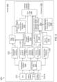
- FIGS 1A and 1B illustrate a system 100 for implementing a RIVL, according to one embodiment.
- the system 100 comprises one or more aiding sensors 110 onboard a vehicle 102; an onboard inertial measurement unit (IMU) 112 operative to produce inertial measurements for vehicle 102; and an onboard radar altimeter 114 operative to produce radar altimeter measurements for vehicle 102.
- a map database 116 onboard vehicle 102 comprises one or more terrain and object maps.
- An onboard navigation system 120 is configured to receive aiding data from aiding sensors 110, and inertial data from IMU 112.
- a navigation filter 121 of navigation system 120 is operative to generate estimated kinematic state statistics for vehicle 102 based on the aiding data and the inertial data.
- a processor 130 onboard vehicle 102 is configured to input horizontal position statistics and vertical position statistics from navigation system 120 into map database 116.
- the processor 130 is operative to compute, based on terrain and object map data from map database 116, an estimated ground/obj ect height and error statistics thereof (block 132); and an estimated ground/object velocity, estimated ground/object acceleration, and error statistics thereof (block 134).
- processer 130 includes a RIVL filter 140 that is configured to receive the estimated ground/object height and error statistics thereof (from block 132); and the estimated ground/object velocity, estimated ground/object acceleration, and error statistics thereof (from block 134).
- the RIVL filter 140 is also configured to receive radar altimeter measurements from radar altimeter 114.
- the RIVL filter 140 is also configured to receive vertical vehicle acceleration and velocity statistics from navigation system 120.
- the RIVL filter 140 is operative to calculate and output estimated vertical statistics for vehicle 102 for landing guidance.
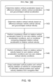
- RIVL filter 140 is generally operative to execute processor readable instructions to determine a relative vertical acceleration based on a difference between a vehicle vertical acceleration and a ground/object vertical acceleration block (142); determine a relative vertical velocity based on a difference between a vehicle vertical velocity and a ground/object vertical velocity (block 143); perform a consistency check on the relative vertical acceleration based on non-zero relative vertical acceleration conditions, and on conditions comparing an integrated relative vertical acceleration to the relative vertical velocity (block 144); and perform a consistency check on the relative vertical velocity based on zero relative vertical acceleration conditions and non-zero relative vertical velocity conditions (block 145).
- the RIVL filter 140 then outputs estimated vertical position and vertical velocity statistics of vehicle 102 for compensation of estimated vertical position and vertical velocity statistics from navigation filter 121 (block 146).
- the navigation filter 121 is configured to output the compensated estimated vertical position and vertical velocity statistics to provide landing guidance for vehicle 102.
- FIG. 2 illustrates a system 200 for implementing a RIVL, according to another embodiment.
- the system 200 comprises a set of aiding sensors 210-1, ... 210-N onboard a vehicle 202; an onboard IMU 212 operative to produce inertial measurements for vehicle 202; and an onboard radar altimeter 214 operative to produce radar altimeter measurements for vehicle 202.
- the aiding sensors include a GPS receiver, a camera, a light detection and ranging (LiDAR) device, a radar device, or the like.
- LiDAR light detection and ranging
- a map database 216 onboard vehicle 202 comprises one or more terrain and object maps.
- the terrain and object maps can include a local ground level map with altitude above the WGS-84 ellipsoid, and an object map with object altitude above the local ground level.
- An onboard barometer 218 is configured to produce barometric pressure measurements for vehicle 202.
- An onboard vehicle navigation system 220 is configured to receive aiding data from aiding sensors 210-1 to 210-N and inertial data from IMU 212.
- a navigation filter 221 of navigation system 220 is operative to generate estimated kinematic state statistics for vehicle 202 based on the aiding data and the inertial data.
- navigation filter 221 is configured to compute and output: horizontal position and standard deviation of the horizontal position estimates (horizontal position statistics) at 222; vertical position and standard deviation of the vertical position estimates (vertical position statistics) at 223; vertical velocity and standard deviation of the vertical velocity estimates (vertical velocity statistics) at 224, and vertical acceleration and standard deviation of the vertical acceleration estimates (vertical acceleration statistics) at 225.
- navigation filter 221 is configured to compute and output roll and pitch statistics at 226, which provide three-dimensional (3D) angular orientation and standard deviation of the angular orientation estimates for vehicle 202.
- the map database 216 is configured to receive the horizontal position and standard deviation of the horizontal position estimates (from 222) and the vertical position and standard deviation of the vertical position estimates (from 223) from navigation system 220.
- An onboard processor 230 is operative to compute, based on terrain/object data from map database 216 and the position statistics, an estimated ground/object height and standard deviation thereof (block 232); and an estimated ground/object velocity, estimated ground/object acceleration, and standard deviation thereof (block 234). These are used for ground modeling, which is described in further detail hereafter.
- processer 230 includes a RIVL filter 240, which is configured to receive ground modeling data based on the estimated ground/object height statistics thereof (from block 232); and ground modeling data based on the estimated ground/object velocity statistics and estimated ground/object acceleration statistics thereof (from block 234).
- the RIVL filter 240 is also configured to receive the vertical velocity statistics (from 224), the vertical acceleration statistics (from 225), and barometric pressure measurements from barometer 218.
- the roll/pitch statistics (from block 226), the radar altimeter measurements from radar altimeter 214, and a radar altimeter angular orientation on vehicle 202 (block 228) are fed to processor 230.
- the radar altimeter angular orientation on vehicle 202 has known measurement axes, and a direction cosine matrix from the radar altimeter measurement frame to the vehicle body axes is known.
- the processor 230 is configured to resolve the radar altimeter measurements into a local horizontal local vertical reference frame, such as a north-east-down (NED) frame (block 236), which is then fed to RIVL filter 240.
- NED north-east-down
- the RIVL filter 240 is operative to calculate and output estimated vertical statistics for vehicle 202 for landing guidance, based on a fusion of all the received input data, as described in further detail hereafter.
- FIG. 3 is a schematic representation of an exemplary operating environment 300 for a vehicle such as a UAM or UAS, implemented with a RIVL filter. As shown, a vehicle trajectory 310 is above a WGS-84 surface 314 and an object 316 such as a building. Various parameters are also shown, including:
- FIG 4 is a schematic representation of another exemplary operating environment 400 for a vehicle implemented with the RIVL filter, in which a vehicle trajectory 410 is above a ground surface 412, which is deviated from a WGS-84 surface 414.
- the ground surface 412 can be above the WGS-84 surface 414, at the WGS-84 surface 414, or below the WGS-84 surface. In this example, the ground surface 412 is elevated above the WGS-84 surface 414.
- An object 416 such as a building has its base located on the ground surface 412.
- Various parameters are also shown, including h veh , h Omap , and h AOL , along with F map and F LZ , which are described above with respect to Figure 3 .
- a radar altimeter measurement, h RA,m is a radar altimeter measured range 420, r RA , to ground surface 412 and object 416 along a boresight of an onboard radar altimeter as the vehicle travels. As shown in Figure 4 , the range measurement may not always be made to ground surface 412 or the top of object 416. Depending on the location and angular orientation of the vehicle, a range measurement can be made to the side of object 416.
- a barometer measurement, h b,m measures the vehicle altitude, h veh , above WGS-84 surface 414.
- the terrain/object maps used with the RIVL filter provide the ground/object altitude, h Omap , above WGS-84 surface 414 based on an estimated vehicle position, h ⁇ Omap .
- ground modeling is to approximate the ground elevation changes and stationary objects on the ground as ground velocities and ground accelerations.
- the ground and stationary objects can be modeled as either steps or ramps.
- the step modeling can be for buildings, trees, and other objects.
- the ramp modeling can be for ground elevation changes.
- the present method approximates steps and ramps using a differentiable function to estimate ground velocity and acceleration.
- the ground/object model function needs to be twice differentiable ( C 2 continuity).
- a general logistics function (sigmoid curve) can be employed as it is a twice differentiable function.
- the logistics function provides a good approximation of the heavyside step function, which is a good approximation for buildings.
- vehicle horizontal position statistics output at 222 are obtained from vehicle navigation system 220.
- An unscented transform is used to compute ground/object height, velocity, acceleration, and their error statistics from the map and the horizontal position statistics from 222.
- unscented transform weighting parameters are selected, and sigma points for the vehicle position statistics are formulated.
- the horizontal vehicle position is correlated to a landing zone map position: x i
- parameters of ground features are selected based on the map: L i , k i , and x 0, i .
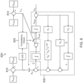
- FIG. 6 is a schematic representation of ground and vehicle position errors in an example operating environment 600 for a vehicle implemented with a RIVL filter.
- a vehicle trajectory 610 is above a ground surface 612, which is elevated over a WGS-84 surface 614.
- An object 616 such as a building is located on ground surface 612.
- an estimated vehicle position horizontal uncertainty ellipse 620 and an estimated vehicle mean horizontal position 622 are provided by vehicle navigation system 220.
- the ground/object height, h Omap , and the ground/object height uncertainties, ⁇ h Omap are determined from the projections of both the estimated vehicle mean horizontal position 622 and estimated vehicle position horizontal uncertainty ellipse 620, as indicated at 630.
- the projection of the estimated vehicle position horizontal uncertainty ellipse 620 on the map can include both the top of object 616 as well as ground surface 612.
- the ground/object height uncertainty, ⁇ h Omap is then a function of different ground terrain (ground surface and/or top of object) and uncertainties of the ground surface height and object height within the map itself.
- the RIVL filter is implemented as a two-input system, which provides input switching and consistency checks.
- the inputs include relative vertical velocity/acceleration, and vertical position of the vehicle.
- the relative vertical velocity, V in is defined as: (vehicle vertical velocity) - (ground/object vertical velocity).
- the relative vertical acceleration, A in is defined as (vehicle vertical acceleration) - (ground/object vertical acceleration).
- the RIVL filter is designed to maintain vertical velocity/acceleration and vertical position inputs consistent with the vehicle's operating environment.
- a changing vertical position can occur with constant relative vertical velocity such that there is zero relative vertical acceleration.
- the RIVL filter can switch to relative vertical velocity inputs to improve its performance.
- Figure 7A illustrates an exemplary design for a RIVL filter 700, implemented in the frequency domain.
- a first subtractor 710 is configured to receive a vehicle vertical acceleration, A veh , a ground/object vertical acceleration, A gnd , and to output the difference as a relative vertical acceleration, A in .
- a second subtractor 712 is configured to receive a vehicle vertical velocity, V veh , a ground/object vertical velocity, V gnd , and to output the difference as a relative vertical velocity, V in .
- the relative vertical acceleration, A in , and the relative vertical velocity, V in are then fed to a complementary filter that is adaptable to use either input for further processing.
- the complementary filter includes a consistency check module 720 and a third order loop 730 that operatively communicates with consistency check module 720 and that is adaptable to use either input.
- the inputs are based on vehicle motion, including non-zero relative acceleration conditions, and zero relative acceleration conditions with non-zero relative velocity conditions.
- the third order loop 730 includes a set of feedback control gains ( K 1 , K 2 , and K 3 ), along with various operators 1 s , s ⁇ D s + 1 and is operative to damp or control the instability of exponentially increasing vertical channel errors in navigation filter designs.
- the consistency check module 720 includes a set of consistency checks that determine whether third order loop 730 uses either the relative vertical acceleration, A in , or the relative vertical velocity, V in .
- N is a user selected number of time steps ( t i )
- ⁇ 1 is a user selected threshold to determine if there is non-zero relative vertical velocity with inputs of relative vertical acceleration integrated over N time steps
- ⁇ 2 is a user selected threshold to determine if the relative vertical velocity is consistent with the integrated vertical velocity.
- the third order loop 730 uses the relative vertical acceleration. If the first consistency check is satisfied, then the third order loop 730 uses the relative vertical acceleration. If the first consistency check is not satisfied, then a second consistency check is used to determine whether relative vertical velocity should be used by third order loop 730.
- the second consistency check can be expressed as: V in , k > ⁇ 3 , where ⁇ 3 is a user selected threshold to determine if there is non-zero relative vertical velocity. If the second consistency check is satisfied, then the third order loop 730 uses the relative vertical velocity as an input. If the second consistency check is not satisfied, then third order loop 730 uses a zero relative vertical acceleration as an input.
- the computed relative vertical acceleration, A in is sent to an integrator 714, which integrates A in to obtain the corresponding integrated vertical velocity, which is sent to consistency check module 720.
- the computed relative vertical velocity, V in is also sent to consistency check module 720.
- Two consistency checks are then performed using integrated A in and the relative vertical velocity, V in . If the first consistency check passes, then the relative vertical acceleration, A in , is directed by a first adaptable input switch 721 to a first input 722 and processed by third order loop 730. If the first consistency check fails and the second consistency check passes, then the relative vertical velocity, V in , is directed by a second adaptable input switch 723 to a second input 724 and processed by third order loop 730. If both consistency checks fail, then a zero relative vertical acceleration, A in , is directed to first input 722 and processed by third order loop 730.
- Figure 7B is a block diagram of a consistency check 750 used for the radar altimeter measurement, h RA,m , when a barometer is employed as an aiding sensor.
- a subtractor 760 is configured to receive a barometer measurement, h b,m , and a ground/ object altitude above the WGS-84 ellipsoid, h Omap , and to output a difference value to a comparator 764. If the difference value is not consistent with the radar altimeter measurement, h RA,m , then the radar altimeter measurement is not used as an input to third order loop 730 ( Fig. 7A ). If the difference value is consistent with the radar altimeter measurement, then the radar altimeter measurement is used as an input to the third order loop 730.
- FIG. 7A the design of the RIVL filter in the frequency domain ( Fig. 7A ) needs to be transitioned to the time domain.
- Figure 8 illustrates such a RIVL filter design 800 that is implemented in the time domain.
- a first subtractor 810 is configured to receive the vehicle vertical acceleration, A veh , the ground/object vertical acceleration, A gnd , and to output the difference as a relative vertical acceleration, A in .
- a second subtractor 812 is configured to receive the vehicle vertical velocity, V veh , the ground/object vertical velocity, V gnd , and to output the difference as a relative vertical velocity, V in .
- the relative vertical acceleration and the relative vertical velocity are then fed to adaptable inputs of the filter section for further processing.
- the filter section again includes a consistency check module 820 and a third order loop 830 that operatively communicates with the adaptable inputs.
- the third order loop section 830 includes a set of feedback control gains ( K 1 , K 2 , and K 3 ), along with various time domain operators.
- the consistency check module 820 again includes a first consistency check that is provided for non-zero relative vertical acceleration, with an input of relative vertical acceleration; and a second consistency check that is provided for near-zero relative vertical acceleration as defined by a user selected threshold and non-zero relative vertical velocity, with inputs of relative vertical acceleration and relative vertical velocity.
- a consistency check can also be used for the radar altimeter measurement when a barometer is employed as an aiding sensor, such as shown in Figure 7B .
- h ⁇ AOL V in + V ;
- V ⁇ A in ⁇ K 2 h AOL ⁇ h m ⁇ K 1 1 ⁇ D ⁇ 1 ⁇ D 2 e ⁇ t ⁇ D h AOL ⁇ h m ⁇ a ;
- a ⁇ K 3 h AOL ⁇ h m ;
- T ⁇ D 1 ⁇ D ⁇ 1 ⁇ D 2 e ⁇ t ⁇ D ;
- K ⁇ K 2 + K 1 T ⁇ D ;
- V ⁇ A in ⁇ K ⁇ h AOL ⁇ h m ⁇ a .
- the statistics of v map can be selected in multiple ways.
- H AOL ⁇ h m h AOL ⁇ h veh + h Omap ⁇ b b ⁇ S b h veh ⁇ v b + v map ;
- h AOL ⁇ h m ⁇ h AOL ⁇ ⁇ h m ;
- E h AOL ⁇ h m E h AOL ⁇ E h veh + E h Omap ⁇ E b b ⁇ E S b h veh ;
- ⁇ h AOL ⁇ ⁇ h m ⁇ h AOL ⁇ ⁇ h veh + ⁇ h Omap ⁇ b b ⁇ S b h veh ;
- ⁇ h AOL ⁇ ⁇ h m ⁇ h AOL ⁇ ⁇ h veh + ⁇ h Omap ⁇ b b ⁇ S b h veh + E S b h veh ⁇ v b + v map ⁇
- ⁇ h ⁇ AOL ⁇ V + ⁇ V in ;
- ⁇ V ⁇ ⁇ A in ⁇ K ⁇ ⁇ h AOL ⁇ ⁇ h veh + ⁇ h Omap ⁇ b b ⁇ ⁇ h veh S b ⁇ v b + v map ⁇ ⁇ a ;
- ⁇ a ⁇ K 3 ⁇ h AOL ⁇ ⁇ h veh + ⁇ h Omap ⁇ b b ⁇ ⁇ h veh S b ⁇ v b + v map ;
- the selection of uncertainty values can be done in multiple ways for the dynamic model.
- the contributing sources of error can be from the navigation filter, such as estimated vehicle height statistics computed by the navigation filter, and estimated vehicle vertical velocity statistics computed by navigation filter.
- FIG. 9 is a flow diagram of an example operational method 900 for a measurement model that can be employed in the RIVL filter.
- a chi-squared test is then performed based on a predicted h RA , m NED and the measured h RA , m NED (block 940). If the chi-squared test is passed, then a measurement update is carried out (block 950). If the chi-squared test is failed, then there is no measurement update (block 960).
- the dynamic model and measurement model described above are then used to estimate the vehicle's vertical velocity and position error statistics by a RIVL Kalman filter. These error statistics are used to compensate the vertical position (altitude) and vertical velocity statistics computed by the navigation filter.
- the Kalman filter is well known to those skilled in the art.
- the processing units and/or other computational devices used in the method and system described herein may be implemented using software, firmware, hardware, or appropriate combinations thereof.
- the processing unit and/or other computational devices may be supplemented by, or incorporated in, specially-designed application-specific integrated circuits (ASICs) or field programmable gate arrays (FPGAs).
- ASICs application-specific integrated circuits
- FPGAs field programmable gate arrays
- the processing unit and/or other computational devices may communicate through an additional transceiver with other computing devices outside of the system, such as those associated with a management system or computing devices associated with other subsystems controlled by the management system.
- the processing unit and/or other computational devices can also include or function with software programs, firmware, or other computer readable instructions for carrying out various process tasks, calculations, and control functions used in the methods and systems described herein.
- program modules include routines, programs, objects, data components, data structures, algorithms, and the like, which perform particular tasks or implement particular abstract data types.
- Instructions for carrying out the various process tasks, calculations, and generation of other data used in the operation of the methods described herein can be implemented in software, firmware, or other computer readable instructions. These instructions are typically stored on appropriate computer program products that include computer readable media used for storage of computer readable instructions or data structures. Such a computer readable medium may be available media that can be accessed by a general purpose or special purpose computer or processor, or any programmable logic device.
- Suitable computer readable storage media may include, for example, non-volatile memory devices including semi-conductor memory devices such as Random Access Memory (RAM), Read Only Memory (ROM), Electrically Erasable Programmable ROM (EEPROM), or flash memory devices; magnetic disks such as internal hard disks or removable disks; optical storage devices such as compact discs (CDs), digital versatile discs (DVDs), Blu-ray discs; or any other media that can be used to carry or store desired program code in the form of computer executable instructions or data structures.
- RAM Random Access Memory
- ROM Read Only Memory
- EEPROM Electrically Erasable Programmable ROM
- flash memory devices such as electrically Erasable Programmable ROM (EEPROM), or flash memory devices
- magnetic disks such as internal hard disks or removable disks
- optical storage devices such as compact discs (CDs), digital versatile discs (DVDs), Blu-ray discs
- CDs compact discs
- DVDs digital versatile discs
- Blu-ray discs any other media that can be used
- Example 1 includes a system comprising: one or more aiding sensors onboard a vehicle; an onboard inertial measurement unit (IMU) operative to produce inertial measurements for the vehicle; an onboard radar altimeter operative to produce radar altimeter measurements for the vehicle; an onboard map database comprising one or more terrain and object maps; an onboard navigation system operative to receive aiding data from the one or more aiding sensors and inertial data from the IMU, the navigation system including a navigation filter operative to generate estimated kinematic state statistics for the vehicle based on the aiding data and the inertial data; and at least one processor onboard the vehicle, the at least one processor operative to execute processor readable instructions to perform a method comprising: inputting horizontal position statistics and vertical position statistics from the navigation filter into the map database; and computing an estimated ground/object height, an estimated ground/object velocity, an estimated ground/object acceleration, and error statistics thereof, based on terrain and object map data from the map database; wherein the at least one processer includes a radar altimeter inertial
- Example 2 includes the system of Example 1, wherein the one or more aiding sensors comprise a global navigation satellite system (GNSS) receiver, a camera, a light detection and ranging (LiDAR) device, or a radar device.
- GNSS global navigation satellite system
- LiDAR light detection and ranging
- Example 3 includes the system of any of Examples 1-2, further comprising an onboard barometer configured to produce barometric pressure measurements for the vehicle, wherein the barometric pressure measurements are fed to the RIVL filter.
- Example 4 includes the system of any of Examples 1-3, wherein the one or more terrain and object maps include a terrain map of local ground level with altitude above, at, or below WGS-84 ellipsoid, and an object map with object altitude above the local ground level.
- Example 5 includes the system of any of Examples 1-4, wherein the estimated kinematic state statistics for the vehicle comprise horizontal position and error statistics, vertical position and error statistics, vertical velocity and error statistics, vertical acceleration and error statistics, and roll/pitch and error statistics.
- Example 6 includes the system of any of Examples 1-5, wherein the roll/pitch and error statistics, the radar altimeter measurements, and a radar altimeter angular orientation on the vehicle are fed to a processing module, which is operative to resolve the radar altimeter measurements into a north-east-down (NED) frame, which is then fed to the RIVL filter.
- a processing module which is operative to resolve the radar altimeter measurements into a north-east-down (NED) frame, which is then fed to the RIVL filter.
- NED north-east-down
- Example 7 includes the system of any of Examples 1-6, wherein the estimated ground/object velocity, ground/object acceleration, and error statistics thereof, are computed using ground modeling to approximate ground elevation changes and stationary objects as ground velocities and ground accelerations.
- Example 8 includes the system of Example 7, wherein the ground modeling uses ramp modeling for the ground elevation changes, and step modeling for the stationary objects.
- Example 9 includes the system of any of Examples 1-8, wherein the RIVL filter comprises: a first subtractor configured to calculate the difference between the vehicle vertical acceleration and the ground/object vertical acceleration, and to output the difference as the relative vertical acceleration; and a second subtractor configured to calculate the difference between the vehicle vertical velocity and the ground vertical velocity, and to output the difference as the relative vertical velocity.
- the RIVL filter comprises: a first subtractor configured to calculate the difference between the vehicle vertical acceleration and the ground/object vertical acceleration, and to output the difference as the relative vertical acceleration; and a second subtractor configured to calculate the difference between the vehicle vertical velocity and the ground vertical velocity, and to output the difference as the relative vertical velocity.
- Example 10 includes the system of Example 9, wherein the RIVL filter further comprises: a consistency check module operatively coupled to the first and second subtractors, the consistency check module operative to perform the consistency checks on the relative vertical acceleration and the relative vertical velocity; a set of adaptable input switches operatively coupled to the consistency check module, the adaptable input switches operative based on motion of the vehicle and changes to the ground terrain, including the non-zero relative acceleration conditions, and the zero relative acceleration conditions with non-zero relative velocity; and a third order loop that operatively communicates with the consistency check module through the adaptable input switches.
- the RIVL filter further comprises: a consistency check module operatively coupled to the first and second subtractors, the consistency check module operative to perform the consistency checks on the relative vertical acceleration and the relative vertical velocity; a set of adaptable input switches operatively coupled to the consistency check module, the adaptable input switches operative based on motion of the vehicle and changes to the ground terrain, including the non-zero relative acceleration conditions, and the zero relative acceleration conditions with non-zero relative
- Example 11 includes the system of Example 10, wherein the third order loop includes a set of feedback control gains, along with associated operators, and is operative to damp or control instability of vertical channel errors.
- Example 12 includes the system of any of Examples 10-11, wherein: the relative vertical acceleration is sent from the first subtractor to an integrator, which integrates the relative vertical acceleration to obtain a corresponding integrated vertical velocity that is sent to the consistency check module; the relative vertical velocity is sent from the second subtractor to the consistency check module; wherein the consistency check module is operative to perform a first consistency check to confirm that the relative vertical acceleration is non-zero, the first consistency check performed between the corresponding integrated vertical velocity and the relative vertical velocity; wherein if the first consistency check is passed, then the non-zero relative vertical acceleration is directed by the adaptable input switches to the third order loop; wherein if the first consistency check fails, then the relative vertical velocity is passed to a second consistency check to confirm that the relative vertical velocity is non-zero; wherein if the second consistency check passes, then the relative vertical velocity is directed by the adaptable input switches to the third order loop; wherein if all the consistency checks fail, then a zero relative vertical acceleration is input to the third order loop.
- Example 13 includes the system of any of Examples 10-12, wherein the consistency check module is further operative to perform a consistency check on the radar altimeter measurements when a barometer is onboard the vehicle.
- Example 14 includes the system of any of Examples 1-13, wherein the RIVL filter is configured for use with a Kalman filter by implementing the RIVL filter with sensor models, map models, vertical motion dynamic models, and sensor measurement models.
- Example 15 includes the system of any of Examples 1-14, wherein the vehicle is an unmanned aircraft system (UAS) vehicle, or an urban air mobility (UAM) vehicle.
- UAS unmanned aircraft system
- UAM urban air mobility
- Example 16 includes a method for providing landing guidance, the method comprising: providing at least one processer onboard a vehicle, the at least one processer including a radar altimeter inertial vertical loop (RIVL) filter; inputting horizontal position statistics and vertical position statistics from an onboard navigation filter into an onboard map database, wherein the navigation filter receives aiding data from one or more aiding sensors onboard the vehicle and inertial data from an inertial measurement unit (IMU) onboard the vehicle; computing an estimated ground/object height, an estimated ground/object velocity, an estimated ground/object acceleration, and error statistics thereof, based on terrain and object map data from the map database; inputting the estimated ground/object height, the estimated ground/object velocity, the estimated ground/object acceleration, and the error statistics thereof into the RIVL filter; inputting radar altimeter measurements from an onboard radar altimeter into the RIVL filter; determining, in the RIVL filter, a relative vertical acceleration based on a difference between a vehicle vertical acceleration and a ground/object vertical acceleration; determining, in
- Example 17 includes the method of Example 16, further comprising: inputting barometric pressure measurements from an onboard barometer into the RIVL filter; and performing a consistency check on the radar altimeter measurements based on the barometric pressure measurements and a terrain map in the map database.
- Example 18 includes the method of any of Examples 16-17, further comprising: resolving the radar altimeter measurements into a north-east-down (NED) frame prior to inputting the radar altimeter measurements into the RIVL filter.
- NED north-east-down
- Example 19 includes the method of any of Examples 16-18, wherein the RIVL filter is configured for use with a Kalman filter by implementing the RIVL filter with sensor models, map models, vertical motion dynamic models, and sensor measurement models.
- Example 20 includes the method of any of Examples 16-19, wherein the vehicle is an unmanned aircraft system (UAS) vehicle, or an urban air mobility (UAM) vehicle.
- UAS unmanned aircraft system
- UAM urban air mobility
Landscapes
- Engineering & Computer Science (AREA)
- Radar, Positioning & Navigation (AREA)
- Remote Sensing (AREA)
- Physics & Mathematics (AREA)
- General Physics & Mathematics (AREA)
- Computer Networks & Wireless Communication (AREA)
- Electromagnetism (AREA)
- Aviation & Aerospace Engineering (AREA)
- Data Mining & Analysis (AREA)
- Automation & Control Theory (AREA)
- Mathematical Physics (AREA)
- Pure & Applied Mathematics (AREA)
- Computational Mathematics (AREA)
- Theoretical Computer Science (AREA)
- Mathematical Optimization (AREA)
- Mathematical Analysis (AREA)
- Evolutionary Biology (AREA)
- Operations Research (AREA)
- Probability & Statistics with Applications (AREA)
- Bioinformatics & Computational Biology (AREA)
- Algebra (AREA)
- Life Sciences & Earth Sciences (AREA)
- Databases & Information Systems (AREA)
- Software Systems (AREA)
- General Engineering & Computer Science (AREA)
- Bioinformatics & Cheminformatics (AREA)
- Navigation (AREA)
- Radar Systems Or Details Thereof (AREA)
Abstract
Description
- Unmanned aircraft systems (UAS) for package delivery and air taxis in Urban Air Mobility (UAM) applications have demanding navigation requirements during landing to support non-certified pilots, automatic systems with potential oversight by remote pilots, and autonomous systems. For example, UAM applications require precision approach and landing to provide for passenger safety and comfort.
- Vehicle vertical position and velocity requirements are extremely demanding for landing zone operations. A hybrid (or operational) mode of Global Positioning System (GPS) aided strapdown inertial navigation systems (INS) cannot satisfy such landing zone requirements without ground-based, differential GPS systems. These systems require power systems and landing zone maintenance personnel to maintain operations, and are subject to jamming.
- The sensor sets of navigation systems for UAS or UAM applications have a need for additional aiding sensors to help satisfy the demanding navigation requirements. One such aiding sensor is the barometer, which has been incorporated into navigation systems using a dedicated vertical loop with complementary filter designs outside the navigation system's filter. This approach has various limitations in that estimation errors of vertical acceleration, and sensor measurement errors, are not used in complementary filter designs. Further, this system may not satisfy the vertical position requirements in the landing zone.
- A system to provide navigation solutions for landing guidance of a vehicle comprises one or more aiding sensors onboard the vehicle; an onboard inertial measurement unit (IMU) operative to produce inertial measurements for the vehicle; an onboard radar altimeter operative to produce radar altimeter measurements for the vehicle; and an onboard map database comprising one or more terrain and object maps. An onboard navigation system is operative to receive aiding data from the one or more aiding sensors and inertial data from the IMU. The navigation system includes a navigation filter operative to generate estimated kinematic state statistics for the vehicle based on the aiding data and the inertial data. At least one onboard processor is operative to execute processor readable instructions to perform a method comprising: inputting horizontal position statistics and vertical position statistics from the navigation filter into the map database; and computing an estimated ground/object height, an estimated ground/object velocity, an estimated ground/object acceleration, and error statistics thereof, based on terrain and object map data from the map database. The processer includes a radar altimeter inertial vertical loop (RIVL) filter that is operative to perform a method comprising: receiving the estimated ground/object height, the estimated ground/object velocity, the estimated ground/object acceleration, and the error statistics thereof; receiving radar altimeter measurements from the radar altimeter; determining a relative vertical acceleration based on a difference between a vehicle vertical acceleration and a ground/object vertical acceleration; determining a relative vertical velocity based on a difference between a vehicle vertical velocity and a ground/object vertical velocity; performing a consistency check on the relative vertical acceleration based on non-zero relative vertical acceleration conditions, and on conditions comparing an integrated relative vertical acceleration to the relative vertical velocity; performing a consistency check on the relative vertical velocity based on zero relative vertical acceleration conditions and non-zero relative vertical velocity conditions; and outputting estimated vertical position and vertical velocity statistics of the vehicle for compensation of estimated vertical position and vertical velocity statistics from the navigation filter. The navigation filter is configured to output the compensated estimated vertical position and vertical velocity statistics to provide landing guidance for the vehicle.
- Features of the present invention will become apparent to those skilled in the art from the following description with reference to the drawings. Understanding that the drawings depict only typical embodiments and are not therefore to be considered limiting in scope, the invention will be described with additional specificity and detail through the use of the accompanying drawings, in which:
-
Figure 1A is a block diagram of a system for implementing a radar altimeter inertial vertical loop (RIVL) filter, according to one embodiment; -
Figure 1B is a flow diagram of a method for operating the RIVL filter in the system ofFigure 1A ; -
Figure 2 is a block diagram of a system for implementing a RIVL filter, according to another embodiment; -
Figure 3 is a schematic representation of an exemplary operating environment for a vehicle implemented with a RIVL filter; -
Figure 4 is a schematic representation of another exemplary operating environment for a vehicle implemented with a RIVL filter; -
Figure 5 is a graphical representation of a step approximation using a logistics function, which can be implemented in a RIVL filter; -
Figure 6 is a schematic representation of ground and vehicle position errors in an example operating environment for a vehicle implemented with a RIVL filter; -
Figure 7A is a block diagram of a RIVL filter, according to one implementation; -
Figure 7B is a block diagram of an optional consistency check used for radar altimeter measurements in the RIVL filter ofFigure 7A ; -
Figure 8 is a block diagram of a RIVL filter, according to another implementation; and -
Figure 9 is a flow diagram of an example operational method for a measurement model that can be employed in a RIVL filter. - In the following detailed description, embodiments are described in sufficient detail to enable those skilled in the art to practice the invention. It is to be understood that other embodiments may be utilized without departing from the scope of the invention. The following detailed description is, therefore, not to be taken in a limiting sense.
- A system and method for implementing a radar altimeter inertial vertical loop (RIVL) is described herein.
- The present system includes use of a radar altimeter, ground maps, and optionally a barometer, to estimate vehicle vertical position and velocity statistics relative to a landing site, where the landing site can be on top of a building or on the ground. The radar altimeter is incorporated into a navigation system using a vertical loop mechanism. In another embodiment, the radar altimeter can be incorporated directly into the navigation system's filter to take advantage of the integrity structure of the navigation system, inertial measurement units (IMUs), and aiding sensors such as Global Positioning System (GPS) devices. The present approach incorporates sensor, map, and navigation errors into the vertical loop mechanism to improve its performance over standard vertical loops.
- As described further hereafter, the vertical loop mechanism can be designed and implemented as a RIVL filter. The RIVL filter is used to fuse various measurements to estimate vertical position and velocity of a vehicle. The present approach provides various features in the RIVL filter, including incorporating maps of landing areas; modeling ground and ground objects (e.g., terrain features, buildings, etc.) using a logistics function; incorporating error models of the ground, ground structures, and sensors into the vertical loop design; and incorporating a switching input feature from relative vehicle vertical acceleration to relative vehicle vertical velocity during constant velocity descents over flat terrain.
- The present method incorporates modeling errors of the ground and ground objects, plus sensor errors, to enable estimation of vertical position errors for integrity, continuity, and availability analysis. The RIVL filter can be used as a standalone system, or can be integrated into a navigation system filter.
- During operation, the RIVL filter is used to track the vehicle altitude above an object level, hAOL, from vehicle approach to landing. There are two contributions to changes in hAOL , including vertical vehicle velocity/acceleration, and ground variations from the World Geodetic System (WGS)-84 surface. WGS-84 is a reference coordinate system used by GPS, and is defined by a standard reference ellipsoid model. A terrain/object map of a landing zone is used to develop ground/object height/velocity/acceleration data, where terrain/object height refers to altitude above the WGS-84 Earth's surface. Ground variations can arise from terrain features on the ground surface, and from buildings or infrastructure on the ground surface. The present method addresses map errors and the effects of estimated vehicle kinematic statistics on hAOL using the RIVL filter.
- With respect to the terrain/object map, a preloaded map of a landing zone area includes fixed stationary and infrastructure objects. The RIVL filter operates using the fixed stationary and infrastructure objects. While the preloaded map of the landing zone area needs to be current, the preloaded map can be updated at the landing zone area by transmitting an updated map to an approaching vehicle.
- The RIVL filter is particularly useful in UAS vehicles for package delivery, and in air taxis such as UAM vehicles. The RIVL filter enables vehicle navigation systems to satisfy UAS and UAM landing zone requirements for both package delivery and air taxi landings using the same approach. This allows for navigating UAS and UAM vehicles in traditional and non-traditional landing zones.
- Further details related to the present system and method are described as follows and with reference to the drawings.
-
Figures 1A and1B illustrate asystem 100 for implementing a RIVL, according to one embodiment. Thesystem 100 comprises one ormore aiding sensors 110 onboard avehicle 102; an onboard inertial measurement unit (IMU) 112 operative to produce inertial measurements forvehicle 102; and anonboard radar altimeter 114 operative to produce radar altimeter measurements forvehicle 102. Amap database 116onboard vehicle 102 comprises one or more terrain and object maps. Anonboard navigation system 120 is configured to receive aiding data from aidingsensors 110, and inertial data from IMU 112. Anavigation filter 121 ofnavigation system 120 is operative to generate estimated kinematic state statistics forvehicle 102 based on the aiding data and the inertial data. - A
processor 130 onboardvehicle 102 is configured to input horizontal position statistics and vertical position statistics fromnavigation system 120 intomap database 116. Theprocessor 130 is operative to compute, based on terrain and object map data frommap database 116, an estimated ground/obj ect height and error statistics thereof (block 132); and an estimated ground/object velocity, estimated ground/object acceleration, and error statistics thereof (block 134). - As depicted in
Figure 1A ,processer 130 includes aRIVL filter 140 that is configured to receive the estimated ground/object height and error statistics thereof (from block 132); and the estimated ground/object velocity, estimated ground/object acceleration, and error statistics thereof (from block 134). TheRIVL filter 140 is also configured to receive radar altimeter measurements fromradar altimeter 114. TheRIVL filter 140 is also configured to receive vertical vehicle acceleration and velocity statistics fromnavigation system 120. TheRIVL filter 140 is operative to calculate and output estimated vertical statistics forvehicle 102 for landing guidance. - For example, as shown in
Figure 1B ,RIVL filter 140 is generally operative to execute processor readable instructions to determine a relative vertical acceleration based on a difference between a vehicle vertical acceleration and a ground/object vertical acceleration block (142); determine a relative vertical velocity based on a difference between a vehicle vertical velocity and a ground/object vertical velocity (block 143); perform a consistency check on the relative vertical acceleration based on non-zero relative vertical acceleration conditions, and on conditions comparing an integrated relative vertical acceleration to the relative vertical velocity (block 144); and perform a consistency check on the relative vertical velocity based on zero relative vertical acceleration conditions and non-zero relative vertical velocity conditions (block 145). TheRIVL filter 140 then outputs estimated vertical position and vertical velocity statistics ofvehicle 102 for compensation of estimated vertical position and vertical velocity statistics from navigation filter 121 (block 146). Thenavigation filter 121 is configured to output the compensated estimated vertical position and vertical velocity statistics to provide landing guidance forvehicle 102. -
Figure 2 illustrates asystem 200 for implementing a RIVL, according to another embodiment. Thesystem 200 comprises a set of aiding sensors 210-1, ... 210-N onboard avehicle 202; anonboard IMU 212 operative to produce inertial measurements forvehicle 202; and anonboard radar altimeter 214 operative to produce radar altimeter measurements forvehicle 202. Examples of the aiding sensors include a GPS receiver, a camera, a light detection and ranging (LiDAR) device, a radar device, or the like. - A
map database 216onboard vehicle 202 comprises one or more terrain and object maps. For example, the terrain and object maps can include a local ground level map with altitude above the WGS-84 ellipsoid, and an object map with object altitude above the local ground level. Anonboard barometer 218 is configured to produce barometric pressure measurements forvehicle 202. - An onboard
vehicle navigation system 220 is configured to receive aiding data from aiding sensors 210-1 to 210-N and inertial data fromIMU 212. Anavigation filter 221 ofnavigation system 220 is operative to generate estimated kinematic state statistics forvehicle 202 based on the aiding data and the inertial data. In particular,navigation filter 221 is configured to compute and output: horizontal position and standard deviation of the horizontal position estimates (horizontal position statistics) at 222; vertical position and standard deviation of the vertical position estimates (vertical position statistics) at 223; vertical velocity and standard deviation of the vertical velocity estimates (vertical velocity statistics) at 224, and vertical acceleration and standard deviation of the vertical acceleration estimates (vertical acceleration statistics) at 225. In addition,navigation filter 221 is configured to compute and output roll and pitch statistics at 226, which provide three-dimensional (3D) angular orientation and standard deviation of the angular orientation estimates forvehicle 202. - The
map database 216 is configured to receive the horizontal position and standard deviation of the horizontal position estimates (from 222) and the vertical position and standard deviation of the vertical position estimates (from 223) fromnavigation system 220. Anonboard processor 230 is operative to compute, based on terrain/object data frommap database 216 and the position statistics, an estimated ground/object height and standard deviation thereof (block 232); and an estimated ground/object velocity, estimated ground/object acceleration, and standard deviation thereof (block 234). These are used for ground modeling, which is described in further detail hereafter. - As depicted in
Figure 2 ,processer 230 includes aRIVL filter 240, which is configured to receive ground modeling data based on the estimated ground/object height statistics thereof (from block 232); and ground modeling data based on the estimated ground/object velocity statistics and estimated ground/object acceleration statistics thereof (from block 234). TheRIVL filter 240 is also configured to receive the vertical velocity statistics (from 224), the vertical acceleration statistics (from 225), and barometric pressure measurements frombarometer 218. - In addition, the roll/pitch statistics (from block 226), the radar altimeter measurements from
radar altimeter 214, and a radar altimeter angular orientation on vehicle 202 (block 228) are fed toprocessor 230. The radar altimeter angular orientation onvehicle 202 has known measurement axes, and a direction cosine matrix from the radar altimeter measurement frame to the vehicle body axes is known. Theprocessor 230 is configured to resolve the radar altimeter measurements into a local horizontal local vertical reference frame, such as a north-east-down (NED) frame (block 236), which is then fed toRIVL filter 240. - The
RIVL filter 240 is operative to calculate and output estimated vertical statistics forvehicle 202 for landing guidance, based on a fusion of all the received input data, as described in further detail hereafter. -
Figure 3 is a schematic representation of anexemplary operating environment 300 for a vehicle such as a UAM or UAS, implemented with a RIVL filter. As shown, avehicle trajectory 310 is above a WGS-84surface 314 and anobject 316 such as a building. Various parameters are also shown, including: - hveh = vehicle altitude above WGS-84 ellipsoid;
- hOmap ≡ object altitude above WGS-84 ellipsoid; and
- hAOL ≡ vehicle altitude above object level.
-
Figure 4 is a schematic representation of anotherexemplary operating environment 400 for a vehicle implemented with the RIVL filter, in which avehicle trajectory 410 is above aground surface 412, which is deviated from a WGS-84surface 414. Theground surface 412 can be above the WGS-84surface 414, at the WGS-84surface 414, or below the WGS-84 surface. In this example, theground surface 412 is elevated above the WGS-84surface 414. Anobject 416 such as a building has its base located on theground surface 412. Various parameters are also shown, including hveh, hOmap, and hAOL, along with Fmap and FLZ , which are described above with respect toFigure 3 . - A radar altimeter measurement, hRA,m, is a radar altimeter measured
range 420, rRA, to groundsurface 412 and object 416 along a boresight of an onboard radar altimeter as the vehicle travels. As shown inFigure 4 , the range measurement may not always be made toground surface 412 or the top ofobject 416. Depending on the location and angular orientation of the vehicle, a range measurement can be made to the side ofobject 416. - When a barometer is used with the RIVL filter, a barometer measurement, hb,m, measures the vehicle altitude, hveh, above WGS-84
surface 414. The terrain/object maps used with the RIVL filter provide the ground/object altitude, hOmap , above WGS-84surface 414 based on an estimated vehicle position, h̃Omap. - Additional details related to implementing the RIVL filter are described as follows.
- The objective of ground modeling is to approximate the ground elevation changes and stationary objects on the ground as ground velocities and ground accelerations. The ground and stationary objects can be modeled as either steps or ramps. The step modeling can be for buildings, trees, and other objects. The ramp modeling can be for ground elevation changes. The present method approximates steps and ramps using a differentiable function to estimate ground velocity and acceleration.
- The ground/object model function needs to be twice differentiable (C2 continuity). In this regard, a general logistics function (sigmoid curve) can be employed as it is a twice differentiable function. The general logistics function can be expressed as:

- L ≡ maximum value of curve ;
- x 0 ≡ horizontal mid-point of curve ; and
- k = growth rate of curve.
- In one example of a step approximation using a logistics function:
- L ≡ building/tree height; and
- k ≡ steepness of curve.
- In one example of a ramp approximation using a logistics function:
- L ≡ ground elevation change from local level to the top of the ramp; and
- k ≡ slope of ramp.
- The logistics function provides a good approximation of the heavyside step function, which is a good approximation for buildings. For example, assume: L = 1, k = 1, and x 0 = 0 so that the logistics function can be written as:


- Initially, vehicle horizontal position statistics output at 222 (
Fig. 2 ) are obtained fromvehicle navigation system 220. An unscented transform is used to compute ground/object height, velocity, acceleration, and their error statistics from the map and the horizontal position statistics from 222. - In an example implementation, unscented transform weighting parameters are selected, and sigma points for the vehicle position statistics are formulated. For each sigma point, the horizontal vehicle position is correlated to a landing zone map position: xi , and parameters of ground features are selected based on the map: Li , ki , and x 0,i . For each sigma point, a ground height is computed as:

- a ground velocity is computed as:

- a ground acceleration is computed as:

- ground/object height: hOmap and δhOmap ;
- ground/object velocity: Vgnd and δVgnd ; and
- ground/object acceleration: Agnd and δAgnd.
-
Figure 6 is a schematic representation of ground and vehicle position errors in anexample operating environment 600 for a vehicle implemented with a RIVL filter. As shown, avehicle trajectory 610 is above aground surface 612, which is elevated over a WGS-84surface 614. Anobject 616 such as a building is located onground surface 612. Also shown is an estimated vehicle positionhorizontal uncertainty ellipse 620 and an estimated vehicle meanhorizontal position 622, both of which are provided byvehicle navigation system 220. The ground/object height, hOmap, and the ground/object height uncertainties, δhOmap , are determined from the projections of both the estimated vehicle meanhorizontal position 622 and estimated vehicle positionhorizontal uncertainty ellipse 620, as indicated at 630. The projection of the estimated vehicle positionhorizontal uncertainty ellipse 620 on the map can include both the top ofobject 616 as well asground surface 612. The ground/object height uncertainty, δhOmap , is then a function of different ground terrain (ground surface and/or top of object) and uncertainties of the ground surface height and object height within the map itself. - The RIVL filter is implemented as a two-input system, which provides input switching and consistency checks. The inputs include relative vertical velocity/acceleration, and vertical position of the vehicle. The relative vertical velocity, Vin , is defined as: (vehicle vertical velocity) - (ground/object vertical velocity). The relative vertical acceleration, Ain , is defined as (vehicle vertical acceleration) - (ground/object vertical acceleration).
- The RIVL filter is designed to maintain vertical velocity/acceleration and vertical position inputs consistent with the vehicle's operating environment. A changing vertical position can occur with constant relative vertical velocity such that there is zero relative vertical acceleration. In this case, the RIVL filter can switch to relative vertical velocity inputs to improve its performance.
-
Figure 7A illustrates an exemplary design for aRIVL filter 700, implemented in the frequency domain. As shown, afirst subtractor 710 is configured to receive a vehicle vertical acceleration, Aveh , a ground/object vertical acceleration, Agnd , and to output the difference as a relative vertical acceleration, Ain . Asecond subtractor 712 is configured to receive a vehicle vertical velocity, Vveh , a ground/object vertical velocity, Vgnd , and to output the difference as a relative vertical velocity, Vin . The relative vertical acceleration, Ain , and the relative vertical velocity, Vin , are then fed to a complementary filter that is adaptable to use either input for further processing. - The complementary filter includes a
consistency check module 720 and athird order loop 730 that operatively communicates withconsistency check module 720 and that is adaptable to use either input. The inputs are based on vehicle motion, including non-zero relative acceleration conditions, and zero relative acceleration conditions with non-zero relative velocity conditions. Thethird order loop 730 includes a set of feedback control gains (K 1, K 2, and K 3), along with various operators
- The
consistency check module 720 includes a set of consistency checks that determine whetherthird order loop 730 uses either the relative vertical acceleration, Ain , or the relative vertical velocity, Vin . A first consistency check can be expressed as:

third order loop 730 uses the relative vertical acceleration. If the first consistency check is not satisfied, then a second consistency check is used to determine whether relative vertical velocity should be used bythird order loop 730. The second consistency check can be expressed as:
third order loop 730 uses the relative vertical velocity as an input. If the second consistency check is not satisfied, thenthird order loop 730 uses a zero relative vertical acceleration as an input. - During operation, the computed relative vertical acceleration, Ain , is sent to an
integrator 714, which integrates Ain to obtain the corresponding integrated vertical velocity, which is sent toconsistency check module 720. The computed relative vertical velocity, Vin , is also sent toconsistency check module 720. Two consistency checks are then performed using integrated Ain and the relative vertical velocity, Vin . If the first consistency check passes, then the relative vertical acceleration, Ain , is directed by a first adaptable input switch 721 to afirst input 722 and processed bythird order loop 730. If the first consistency check fails and the second consistency check passes, then the relative vertical velocity, Vin , is directed by a secondadaptable input switch 723 to asecond input 724 and processed bythird order loop 730. If both consistency checks fail, then a zero relative vertical acceleration, Ain , is directed tofirst input 722 and processed bythird order loop 730. -
Figure 7B is a block diagram of aconsistency check 750 used for the radar altimeter measurement, hRA,m , when a barometer is employed as an aiding sensor. Asubtractor 760 is configured to receive a barometer measurement, hb,m , and a ground/ object altitude above the WGS-84 ellipsoid, hOmap , and to output a difference value to acomparator 764. If the difference value is not consistent with the radar altimeter measurement, hRA,m , then the radar altimeter measurement is not used as an input to third order loop 730 (Fig. 7A ). If the difference value is consistent with the radar altimeter measurement, then the radar altimeter measurement is used as an input to thethird order loop 730. - In order to provide for modeling and use with a Kalman filter, the design of the RIVL filter in the frequency domain (
Fig. 7A ) needs to be transitioned to the time domain.Figure 8 illustrates such aRIVL filter design 800 that is implemented in the time domain. Correspondingly, afirst subtractor 810 is configured to receive the vehicle vertical acceleration, Aveh , the ground/object vertical acceleration, Agnd , and to output the difference as a relative vertical acceleration, Ain . Asecond subtractor 812 is configured to receive the vehicle vertical velocity, Vveh , the ground/object vertical velocity, Vgnd , and to output the difference as a relative vertical velocity, Vin . The relative vertical acceleration and the relative vertical velocity are then fed to adaptable inputs of the filter section for further processing. - The filter section again includes a
consistency check module 820 and athird order loop 830 that operatively communicates with the adaptable inputs. The thirdorder loop section 830 includes a set of feedback control gains (K 1, K 2, and K 3), along with various time domain operators. Theconsistency check module 820 again includes a first consistency check that is provided for non-zero relative vertical acceleration, with an input of relative vertical acceleration; and a second consistency check that is provided for near-zero relative vertical acceleration as defined by a user selected threshold and non-zero relative vertical velocity, with inputs of relative vertical acceleration and relative vertical velocity. A consistency check can also be used for the radar altimeter measurement when a barometer is employed as an aiding sensor, such as shown inFigure 7B . - Further details related to various models for use of the RIVL filter with a Kalman filter are described as follows.
- The following equations can be used to provide a transition to filter models in the RIVL filter.


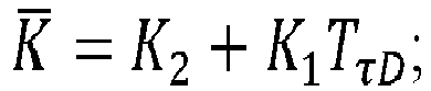


- δhAOL = hAOL - E{hAOL };
- δV = V - E{V};
- δa = a - E{a};
- δhm = hm - E{hm };
- δVin = Vin - E{Vin }; and
- δAin = Ain - E{Ain }.
- A barometer model, which provides vehicle height above the WGS-84 ellipsoid, can expressed by the following equations:


- where bb ≡ barometer bias;
- E{bb (t)} = 0;
-

- where wb ≡ barometer bias, driving white noise; and
vb ≡ barometer, measurement white noise;- E{vSb (t)} = 0;
-

- where wsb ≡ barometer scale factor, driving white noise;
- E{wSb (t)} = 0;
-

- A map model, which provides object height above the WGS-84 ellipsoid, can be expressed by the following equation:

- For the radar altimeter measurement consistency check, the height above object level, hm , is equal to the barometer measurement, hb,m , minus the map measurement, h̃Omap , expressed as:



- The following additional equations for the HAOL - hm term can be used in the transition to filter models in the RIVL filter.


- The following equations can be used to provide a dynamic model for the RIVL filter.


- The selection of uncertainty values can be done in multiple ways for the dynamic model. The contributing sources of error can be from the navigation filter, such as estimated vehicle height statistics computed by the navigation filter, and estimated vehicle vertical velocity statistics computed by navigation filter. Other sources of error can be from the computed ground velocity and ground acceleration. Examples of error terms include:



-
Figure 9 is a flow diagram of an exampleoperational method 900 for a measurement model that can be employed in the RIVL filter. Initially, estimated vehicle roll and pitch statistics (block 910) are received from a vehicle navigation system, along with vehicle radar altimeter measurements,


- The following equations can be used to provide the measurement model in the RIVL filter.


- The dynamic model and measurement model described above are then used to estimate the vehicle's vertical velocity and position error statistics by a RIVL Kalman filter. These error statistics are used to compensate the vertical position (altitude) and vertical velocity statistics computed by the navigation filter. The Kalman filter is well known to those skilled in the art.
- The processing units and/or other computational devices used in the method and system described herein may be implemented using software, firmware, hardware, or appropriate combinations thereof. The processing unit and/or other computational devices may be supplemented by, or incorporated in, specially-designed application-specific integrated circuits (ASICs) or field programmable gate arrays (FPGAs). In some implementations, the processing unit and/or other computational devices may communicate through an additional transceiver with other computing devices outside of the system, such as those associated with a management system or computing devices associated with other subsystems controlled by the management system. The processing unit and/or other computational devices can also include or function with software programs, firmware, or other computer readable instructions for carrying out various process tasks, calculations, and control functions used in the methods and systems described herein.
- The methods described herein may be implemented by computer executable instructions, such as program modules or components, which are executed by at least one processor or processing unit. Generally, program modules include routines, programs, objects, data components, data structures, algorithms, and the like, which perform particular tasks or implement particular abstract data types.
- Instructions for carrying out the various process tasks, calculations, and generation of other data used in the operation of the methods described herein can be implemented in software, firmware, or other computer readable instructions. These instructions are typically stored on appropriate computer program products that include computer readable media used for storage of computer readable instructions or data structures. Such a computer readable medium may be available media that can be accessed by a general purpose or special purpose computer or processor, or any programmable logic device.
- Suitable computer readable storage media may include, for example, non-volatile memory devices including semi-conductor memory devices such as Random Access Memory (RAM), Read Only Memory (ROM), Electrically Erasable Programmable ROM (EEPROM), or flash memory devices; magnetic disks such as internal hard disks or removable disks; optical storage devices such as compact discs (CDs), digital versatile discs (DVDs), Blu-ray discs; or any other media that can be used to carry or store desired program code in the form of computer executable instructions or data structures.
- Example 1 includes a system comprising: one or more aiding sensors onboard a vehicle; an onboard inertial measurement unit (IMU) operative to produce inertial measurements for the vehicle; an onboard radar altimeter operative to produce radar altimeter measurements for the vehicle; an onboard map database comprising one or more terrain and object maps; an onboard navigation system operative to receive aiding data from the one or more aiding sensors and inertial data from the IMU, the navigation system including a navigation filter operative to generate estimated kinematic state statistics for the vehicle based on the aiding data and the inertial data; and at least one processor onboard the vehicle, the at least one processor operative to execute processor readable instructions to perform a method comprising: inputting horizontal position statistics and vertical position statistics from the navigation filter into the map database; and computing an estimated ground/object height, an estimated ground/object velocity, an estimated ground/object acceleration, and error statistics thereof, based on terrain and object map data from the map database; wherein the at least one processer includes a radar altimeter inertial vertical loop (RIVL) filter, wherein the RIVL filter is operative to perform a method comprising: receiving the estimated ground/obj ect height, the estimated ground/obj ect velocity, the estimated ground/object acceleration, and the error statistics thereof; receiving radar altimeter measurements from the radar altimeter; determining a relative vertical acceleration based on a difference between a vehicle vertical acceleration and a ground/object vertical acceleration; determining a relative vertical velocity based on a difference between a vehicle vertical velocity and a ground/object vertical velocity; performing a consistency check on the relative vertical acceleration based on non-zero relative vertical acceleration conditions, and on conditions comparing an integrated relative vertical acceleration to the relative vertical velocity; performing a consistency check on the relative vertical velocity based on zero relative vertical acceleration conditions and non-zero relative vertical velocity conditions; and outputting estimated vertical position and vertical velocity statistics of the vehicle for compensation of estimated vertical position and vertical velocity statistics from the navigation filter; wherein the navigation filter is configured to output the compensated estimated vertical position and vertical velocity statistics to provide landing guidance for the vehicle.
- Example 2 includes the system of Example 1, wherein the one or more aiding sensors comprise a global navigation satellite system (GNSS) receiver, a camera, a light detection and ranging (LiDAR) device, or a radar device.
- Example 3 includes the system of any of Examples 1-2, further comprising an onboard barometer configured to produce barometric pressure measurements for the vehicle, wherein the barometric pressure measurements are fed to the RIVL filter.
- Example 4 includes the system of any of Examples 1-3, wherein the one or more terrain and object maps include a terrain map of local ground level with altitude above, at, or below WGS-84 ellipsoid, and an object map with object altitude above the local ground level.
- Example 5 includes the system of any of Examples 1-4, wherein the estimated kinematic state statistics for the vehicle comprise horizontal position and error statistics, vertical position and error statistics, vertical velocity and error statistics, vertical acceleration and error statistics, and roll/pitch and error statistics.
- Example 6 includes the system of any of Examples 1-5, wherein the roll/pitch and error statistics, the radar altimeter measurements, and a radar altimeter angular orientation on the vehicle are fed to a processing module, which is operative to resolve the radar altimeter measurements into a north-east-down (NED) frame, which is then fed to the RIVL filter.
- Example 7 includes the system of any of Examples 1-6, wherein the estimated ground/object velocity, ground/object acceleration, and error statistics thereof, are computed using ground modeling to approximate ground elevation changes and stationary objects as ground velocities and ground accelerations.
- Example 8 includes the system of Example 7, wherein the ground modeling uses ramp modeling for the ground elevation changes, and step modeling for the stationary objects.
- Example 9 includes the system of any of Examples 1-8, wherein the RIVL filter comprises: a first subtractor configured to calculate the difference between the vehicle vertical acceleration and the ground/object vertical acceleration, and to output the difference as the relative vertical acceleration; and a second subtractor configured to calculate the difference between the vehicle vertical velocity and the ground vertical velocity, and to output the difference as the relative vertical velocity.
- Example 10 includes the system of Example 9, wherein the RIVL filter further comprises: a consistency check module operatively coupled to the first and second subtractors, the consistency check module operative to perform the consistency checks on the relative vertical acceleration and the relative vertical velocity; a set of adaptable input switches operatively coupled to the consistency check module, the adaptable input switches operative based on motion of the vehicle and changes to the ground terrain, including the non-zero relative acceleration conditions, and the zero relative acceleration conditions with non-zero relative velocity; and a third order loop that operatively communicates with the consistency check module through the adaptable input switches.
- Example 11 includes the system of Example 10, wherein the third order loop includes a set of feedback control gains, along with associated operators, and is operative to damp or control instability of vertical channel errors.
- Example 12 includes the system of any of Examples 10-11, wherein: the relative vertical acceleration is sent from the first subtractor to an integrator, which integrates the relative vertical acceleration to obtain a corresponding integrated vertical velocity that is sent to the consistency check module; the relative vertical velocity is sent from the second subtractor to the consistency check module; wherein the consistency check module is operative to perform a first consistency check to confirm that the relative vertical acceleration is non-zero, the first consistency check performed between the corresponding integrated vertical velocity and the relative vertical velocity; wherein if the first consistency check is passed, then the non-zero relative vertical acceleration is directed by the adaptable input switches to the third order loop; wherein if the first consistency check fails, then the relative vertical velocity is passed to a second consistency check to confirm that the relative vertical velocity is non-zero; wherein if the second consistency check passes, then the relative vertical velocity is directed by the adaptable input switches to the third order loop; wherein if all the consistency checks fail, then a zero relative vertical acceleration is input to the third order loop.
- Example 13 includes the system of any of Examples 10-12, wherein the consistency check module is further operative to perform a consistency check on the radar altimeter measurements when a barometer is onboard the vehicle.
- Example 14 includes the system of any of Examples 1-13, wherein the RIVL filter is configured for use with a Kalman filter by implementing the RIVL filter with sensor models, map models, vertical motion dynamic models, and sensor measurement models.
- Example 15 includes the system of any of Examples 1-14, wherein the vehicle is an unmanned aircraft system (UAS) vehicle, or an urban air mobility (UAM) vehicle.
- Example 16 includes a method for providing landing guidance, the method comprising: providing at least one processer onboard a vehicle, the at least one processer including a radar altimeter inertial vertical loop (RIVL) filter; inputting horizontal position statistics and vertical position statistics from an onboard navigation filter into an onboard map database, wherein the navigation filter receives aiding data from one or more aiding sensors onboard the vehicle and inertial data from an inertial measurement unit (IMU) onboard the vehicle; computing an estimated ground/object height, an estimated ground/object velocity, an estimated ground/object acceleration, and error statistics thereof, based on terrain and object map data from the map database; inputting the estimated ground/object height, the estimated ground/object velocity, the estimated ground/object acceleration, and the error statistics thereof into the RIVL filter; inputting radar altimeter measurements from an onboard radar altimeter into the RIVL filter; determining, in the RIVL filter, a relative vertical acceleration based on a difference between a vehicle vertical acceleration and a ground/object vertical acceleration; determining, in the RIVL filter, a relative vertical velocity based on a difference between a vehicle vertical velocity and a ground/object vertical velocity; performing, in the RIVL filter, a consistency check on the relative vertical acceleration based on non-zero relative vertical acceleration conditions, and on conditions comparing an integrated relative vertical acceleration to the relative vertical velocity; performing, in the RIVL filter, a consistency check on the relative vertical velocity based on zero relative vertical acceleration conditions and non-zero relative vertical velocity conditions; outputting, from the RIVL filter, estimated vertical position and vertical velocity statistics of the vehicle for compensation of estimated vertical position and vertical velocity statistics from the navigation filter; and outputting, from compensated navigation filter outputs, the compensated estimated vertical position and vertical velocity statistics to provide for landing guidance of the vehicle.
- Example 17 includes the method of Example 16, further comprising: inputting barometric pressure measurements from an onboard barometer into the RIVL filter; and performing a consistency check on the radar altimeter measurements based on the barometric pressure measurements and a terrain map in the map database.
- Example 18 includes the method of any of Examples 16-17, further comprising: resolving the radar altimeter measurements into a north-east-down (NED) frame prior to inputting the radar altimeter measurements into the RIVL filter.
- Example 19 includes the method of any of Examples 16-18, wherein the RIVL filter is configured for use with a Kalman filter by implementing the RIVL filter with sensor models, map models, vertical motion dynamic models, and sensor measurement models.
- Example 20 includes the method of any of Examples 16-19, wherein the vehicle is an unmanned aircraft system (UAS) vehicle, or an urban air mobility (UAM) vehicle.
- From the foregoing, it will be appreciated that, although specific embodiments have been described herein for purposes of illustration, various modifications may be made without deviating from the scope of the disclosure. Thus, the described embodiments are to be considered in all respects only as illustrative and not restrictive. In addition, all changes that come within the meaning and range of equivalency of the claims are to be embraced within their scope.

Claims (10)
- A system comprising:one or more aiding sensors onboard a vehicle;an onboard inertial measurement unit (IMU) operative to produce inertial measurements for the vehicle;an onboard radar altimeter operative to produce radar altimeter measurements for the vehicle;an onboard map database comprising one or more terrain and object maps;an onboard navigation system operative to receive aiding data from the one or more aiding sensors and inertial data from the IMU, the navigation system including a navigation filter operative to generate estimated kinematic state statistics for the vehicle based on the aiding data and the inertial data; andat least one processor onboard the vehicle, the at least one processor operative to execute processor readable instructions to perform a method comprising:inputting horizontal position statistics and vertical position statistics from the navigation filter into the map database; andcomputing an estimated ground/object height, an estimated ground/object velocity, an estimated ground/object acceleration, and error statistics thereof, based on terrain and object map data from the map database;wherein the at least one processer includes a radar altimeter inertial vertical loop (RIVL) filter, wherein the RIVL filter is operative to perform a method comprising:receiving the estimated ground/object height, the estimated ground/object velocity, the estimated ground/object acceleration, and the error statistics thereof;receiving radar altimeter measurements from the radar altimeter;determining a relative vertical acceleration based on a difference between a vehicle vertical acceleration and a ground/object vertical acceleration;determining a relative vertical velocity based on a difference between a vehicle vertical velocity and a ground/object vertical velocity;performing a consistency check on the relative vertical acceleration based on non-zero relative vertical acceleration conditions, and on conditions comparing an integrated relative vertical acceleration to the relative vertical velocity;performing a consistency check on the relative vertical velocity based on zero relative vertical acceleration conditions and non-zero relative vertical velocity conditions; andoutputting estimated vertical position and vertical velocity statistics of the vehicle for compensation of estimated vertical position and vertical velocity statistics from the navigation filter;wherein the navigation filter is configured to output the compensated estimated vertical position and vertical velocity statistics to provide landing guidance for the vehicle.
- The system of claim 1, further comprising an onboard barometer configured to produce barometric pressure measurements for the vehicle, wherein the barometric pressure measurements are fed to the RIVL filter.
- The system of claim 1, wherein:the one or more terrain and object maps include a terrain map of local ground level with altitude above, at, or below WGS-84 ellipsoid, and an object map with object altitude above the local ground level; andthe estimated kinematic state statistics for the vehicle comprise horizontal position and error statistics, vertical position and error statistics, vertical velocity and error statistics, vertical acceleration and error statistics, and roll/pitch and error statistics.
- The system of claim 1, wherein the roll/pitch and error statistics, the radar altimeter measurements, and a radar altimeter angular orientation on the vehicle are fed to a processing module, which is operative to resolve the radar altimeter measurements into a north-east-down (NED) frame, which is then fed to the RIVL filter.
- The system of claim 1, wherein the RIVL filter comprises:a first subtractor configured to calculate the difference between the vehicle vertical acceleration and the ground/object vertical acceleration, and to output the difference as the relative vertical acceleration;a second subtractor configured to calculate the difference between the vehicle vertical velocity and the ground vertical velocity, and to output the difference as the relative vertical velocity;a consistency check module operatively coupled to the first and second subtractors, the consistency check module operative to perform the consistency checks on the relative vertical acceleration and the relative vertical velocity;a set of adaptable input switches operatively coupled to the consistency check module, the adaptable input switches operative based on motion of the vehicle and changes to the ground terrain, including the non-zero relative acceleration conditions, and the zero relative acceleration conditions with non-zero relative velocity; anda third order loop that operatively communicates with the consistency check module through the adaptable input switches.
- The system of claim 5, wherein:the relative vertical acceleration is sent from the first subtractor to an integrator, which integrates the relative vertical acceleration to obtain a corresponding integrated vertical velocity that is sent to the consistency check module;the relative vertical velocity is sent from the second subtractor to the consistency check module;wherein the consistency check module is operative to perform a first consistency check to confirm that the relative vertical acceleration is non-zero, the first consistency check performed between the corresponding integrated vertical velocity and the relative vertical velocity;wherein if the first consistency check is passed, then the non-zero relative vertical acceleration is directed by the adaptable input switches to the third order loop;wherein if the first consistency check fails, then the relative vertical velocity is passed to a second consistency check to confirm that the relative vertical velocity is non-zero;wherein if the second consistency check passes, then the relative vertical velocity is directed by the adaptable input switches to the third order loop;wherein if all the consistency checks fail, then a zero relative vertical acceleration is input to the third order loop.
- The system of claim 5, wherein the consistency check module is further operative to perform a consistency check on the radar altimeter measurements when a barometer is onboard the vehicle.
- The system of claim 1, wherein the RIVL filter is configured for use with a Kalman filter by implementing the RIVL filter with sensor models, map models, vertical motion dynamic models, and sensor measurement models.
- The system of claim 1, wherein the vehicle is an unmanned aircraft system (UAS) vehicle, or an urban air mobility (UAM) vehicle.
- A method for providing landing guidance, the method comprising:providing at least one processer onboard a vehicle, the at least one processer including a radar altimeter inertial vertical loop (RIVL) filter;inputting horizontal position statistics and vertical position statistics from an onboard navigation filter into an onboard map database, wherein the navigation filter receives aiding data from one or more aiding sensors onboard the vehicle and inertial data from an inertial measurement unit (IMU) onboard the vehicle;computing an estimated ground/object height, an estimated ground/object velocity, an estimated ground/object acceleration, and error statistics thereof, based on terrain and object map data from the map database;inputting the estimated ground/object height, the estimated ground/object velocity, the estimated ground/object acceleration, and the error statistics thereof into the RIVL filter;inputting radar altimeter measurements from an onboard radar altimeter into the RIVL filter;determining, in the RIVL filter, a relative vertical acceleration based on a difference between a vehicle vertical acceleration and a ground/object vertical acceleration;determining, in the RIVL filter, a relative vertical velocity based on a difference between a vehicle vertical velocity and a ground/object vertical velocity;performing, in the RIVL filter, a consistency check on the relative vertical acceleration based on non-zero relative vertical acceleration conditions, and on conditions comparing an integrated relative vertical acceleration to the relative vertical velocity;performing, in the RIVL filter, a consistency check on the relative vertical velocity based on zero relative vertical acceleration conditions and non-zero relative vertical velocity conditions;outputting, from the RIVL filter, estimated vertical position and vertical velocity statistics of the vehicle for compensation of estimated vertical position and vertical velocity statistics from the navigation filter; andoutputting, from compensated navigation filter outputs, the compensated estimated vertical position and vertical velocity statistics to provide for landing guidance of the vehicle.
Applications Claiming Priority (1)
| Application Number | Priority Date | Filing Date | Title |
|---|---|---|---|
| US17/586,545 US11879969B2 (en) | 2022-01-27 | 2022-01-27 | Radar altimeter inertial vertical loop |
Publications (2)
| Publication Number | Publication Date |
|---|---|
| EP4220079A1 true EP4220079A1 (en) | 2023-08-02 |
| EP4220079B1 EP4220079B1 (en) | 2026-03-04 |
Family
ID=84901729
Family Applications (1)
| Application Number | Title | Priority Date | Filing Date |
|---|---|---|---|
| EP23150824.3A Active EP4220079B1 (en) | 2022-01-27 | 2023-01-09 | Radar altimeter inertial vertical loop |
Country Status (3)
| Country | Link |
|---|---|
| US (1) | US11879969B2 (en) |
| EP (1) | EP4220079B1 (en) |
| CN (1) | CN116559861A (en) |
Cited By (2)
| Publication number | Priority date | Publication date | Assignee | Title |
|---|---|---|---|---|
| CN116700319A (en) * | 2023-08-04 | 2023-09-05 | 西安交通大学 | Aerial robot autonomous take-off and landing system and method based on micro-radar array |
| EP4498113A1 (en) * | 2023-07-27 | 2025-01-29 | Honeywell International s.r.o | Radar inertial vertical hybrid filter scheme resistant to terrain variations |
Families Citing this family (2)
| Publication number | Priority date | Publication date | Assignee | Title |
|---|---|---|---|---|
| EP4439014A1 (en) * | 2023-03-30 | 2024-10-02 | Zenseact AB | Vehicle localization |
| GB2630148B (en) * | 2023-05-19 | 2026-04-22 | Modini Ltd | Unmanned aerial vehicle electronics |
Citations (2)
| Publication number | Priority date | Publication date | Assignee | Title |
|---|---|---|---|---|
| US20040267444A1 (en) * | 2001-11-27 | 2004-12-30 | Jacques Coatantiec | Hybrid intertial navigation unit with improved altitude integrity |
| DE102004040249A1 (en) * | 2003-08-30 | 2005-05-25 | Eads Deutschland Gmbh | Low-level guidance system, low-level guidance warning system, low-level command warning generator and low-level guidance method |
Family Cites Families (18)
| Publication number | Priority date | Publication date | Assignee | Title |
|---|---|---|---|---|
| US4882697A (en) | 1987-04-16 | 1989-11-21 | Honeywell Inc. | Stabilization control circuit for vertical position in an inertial navigator |
| US4884697A (en) | 1988-06-21 | 1989-12-05 | Takacs Peter Z | Surface profiling interferometer |
| US6492934B1 (en) | 2001-08-06 | 2002-12-10 | Rockwell Collins | Method of deriving ground speed for descending aircraft |
| US7145501B1 (en) | 2005-09-26 | 2006-12-05 | Honeywell International Inc. | Methods and systems for measuring terrain height |
| US8509965B2 (en) * | 2006-12-12 | 2013-08-13 | American Gnc Corporation | Integrated collision avoidance system for air vehicle |
| FR2961897B1 (en) | 2010-06-25 | 2012-07-13 | Thales Sa | NAVIGATION FILTER FOR A FIELD CORRELATION NAVIGATION SYSTEM |
| US9404754B2 (en) | 2013-03-25 | 2016-08-02 | Raytheon Company | Autonomous range-only terrain aided navigation |
| US10473466B2 (en) | 2016-12-09 | 2019-11-12 | Honeywell International Inc. | Apparatus and method for data-based referenced navigation |
| US10641885B2 (en) * | 2017-07-21 | 2020-05-05 | Honeywell International Inc. | Systems and methods for measuring velocity and acceleration with a radar altimeter |
| US10946979B2 (en) * | 2018-04-13 | 2021-03-16 | The Boeing Company | Apparatus for controlling vehicle impact absorption systems and related methods |
| GB2575971A (en) | 2018-07-23 | 2020-02-05 | Atlantic Inertial Systems Ltd | A navigation system |
| US11783707B2 (en) * | 2018-10-09 | 2023-10-10 | Ford Global Technologies, Llc | Vehicle path planning |
| US11495030B1 (en) * | 2019-12-12 | 2022-11-08 | Amazon Technologies, Inc. | Systems and methods for creating an occupancy map based on an objective function |
| US11821733B2 (en) | 2020-01-21 | 2023-11-21 | The Boeing Company | Terrain referenced navigation system with generic terrain sensors for correcting an inertial navigation solution |
| US11535394B2 (en) * | 2020-08-10 | 2022-12-27 | The Boeing Company | Aircraft landing assistance method and memory storage device including instructions for performing an aircraft landing assistance method |
| US11987382B2 (en) * | 2021-02-17 | 2024-05-21 | Merlin Labs, Inc. | Method for aircraft localization and control |
| EP4327317A1 (en) * | 2021-04-20 | 2024-02-28 | Alauda Aeronautics Pty Ltd | System infrastructure for manned vertical take-off and landing aerial vehicles |
| US12065158B2 (en) * | 2021-08-09 | 2024-08-20 | Lyft, Inc. | Systems and methods for detecting an environment external to a personal mobile vehicle in a fleet management system |
-
2022
- 2022-01-27 US US17/586,545 patent/US11879969B2/en active Active
- 2022-12-23 CN CN202211663673.6A patent/CN116559861A/en active Pending
-
2023
- 2023-01-09 EP EP23150824.3A patent/EP4220079B1/en active Active
Patent Citations (2)
| Publication number | Priority date | Publication date | Assignee | Title |
|---|---|---|---|---|
| US20040267444A1 (en) * | 2001-11-27 | 2004-12-30 | Jacques Coatantiec | Hybrid intertial navigation unit with improved altitude integrity |
| DE102004040249A1 (en) * | 2003-08-30 | 2005-05-25 | Eads Deutschland Gmbh | Low-level guidance system, low-level guidance warning system, low-level command warning generator and low-level guidance method |
Cited By (4)
| Publication number | Priority date | Publication date | Assignee | Title |
|---|---|---|---|---|
| EP4498113A1 (en) * | 2023-07-27 | 2025-01-29 | Honeywell International s.r.o | Radar inertial vertical hybrid filter scheme resistant to terrain variations |
| US12644708B2 (en) | 2023-07-27 | 2026-06-02 | Honeywell International S.R.O. | Radar inertial vertical hybrid filter scheme resistant to terrain variations |
| CN116700319A (en) * | 2023-08-04 | 2023-09-05 | 西安交通大学 | Aerial robot autonomous take-off and landing system and method based on micro-radar array |
| CN116700319B (en) * | 2023-08-04 | 2023-10-20 | 西安交通大学 | Autonomous take-off and landing system and method for aerial robot based on micro radar array |
Also Published As
| Publication number | Publication date |
|---|---|
| US11879969B2 (en) | 2024-01-23 |
| EP4220079B1 (en) | 2026-03-04 |
| CN116559861A (en) | 2023-08-08 |
| US20230236316A1 (en) | 2023-07-27 |
Similar Documents
| Publication | Publication Date | Title |
|---|---|---|
| EP4220079B1 (en) | Radar altimeter inertial vertical loop | |
| Karlsson et al. | The future of automotive localization algorithms: Available, reliable, and scalable localization: Anywhere and anytime | |
| Abosekeen et al. | A novel multi-level integrated navigation system for challenging GNSS environments | |
| KR20210111180A (en) | Method, apparatus, computing device and computer-readable storage medium for positioning | |
| CN112292581A (en) | Relative Atlas of Self-Driving Vehicles and Their Generation | |
| US20230406320A1 (en) | Method for detecting surface gradient of unstructured road based on lidar | |
| Dill et al. | 3D Multi‐copter navigation and mapping using GPS, inertial, and LiDAR | |
| Wang et al. | UGV‐UAV robust cooperative positioning algorithm with object detection | |
| JP7396472B2 (en) | Position measuring device, positioning method, and program | |
| Iqbal et al. | Experimental results on an integrated GPS and multisensor system for land vehicle positioning | |
| Xu et al. | An enhanced positioning algorithm module for low-cost GNSS/MEMS integration based on matching straight lane lines in HD maps | |
| Mahmoud et al. | Land vehicle navigation using low-cost integrated smartphone GNSS mems and map matching technique | |
| Klein et al. | LiDAR and INS fusion in periods of GPS outages for mobile laser scanning mapping systems | |
| Qu et al. | Enhancing GNSS and INS integration for high-precision and continuous positioning using odometer trained with TSFNN | |
| US20230314141A1 (en) | Terrain referenced navigation system with generic terrain sensors for correcting an inertial navigation solution | |
| Anhalt et al. | Concept, implementation, and performance comparison of a particle filter for accurate vehicle localization using road profile data | |
| Elsheikh et al. | Multisensor precise positioning for automated and connected vehicles | |
| Campbell et al. | Terrain‐Referenced Positioning Using Airborne Laser Scanner | |
| Noureldin et al. | A framework for multi-sensor positioning and mapping for autonomous vehicles | |
| Barrios et al. | Predicting vehicle trajectory | |
| Wankerl et al. | Evaluation of a segmented navigation filter approach for vehicle self-localization in urban environment | |
| Weber et al. | Analysis and testing of data link time of flight measurements in data fusion algorithms for positioning of UAV | |
| Mikov et al. | Map-Aided Automotive Dead-Reckoning using Rao-Blackwellized Particle Filter | |
| CN113324539A (en) | SINS/SRS/CNS multi-source fusion autonomous integrated navigation method | |
| Salmon | An experimental exploration of low-cost sensor and vehicle model solutions for precision ground vehicle navigation |
Legal Events
| Date | Code | Title | Description |
|---|---|---|---|
| PUAI | Public reference made under article 153(3) epc to a published international application that has entered the european phase |
Free format text: ORIGINAL CODE: 0009012 |
|
| STAA | Information on the status of an ep patent application or granted ep patent |
Free format text: STATUS: THE APPLICATION HAS BEEN PUBLISHED |
|
| AK | Designated contracting states |
Kind code of ref document: A1 Designated state(s): AL AT BE BG CH CY CZ DE DK EE ES FI FR GB GR HR HU IE IS IT LI LT LU LV MC ME MK MT NL NO PL PT RO RS SE SI SK SM TR |
|
| STAA | Information on the status of an ep patent application or granted ep patent |
Free format text: STATUS: REQUEST FOR EXAMINATION WAS MADE |
|
| 17P | Request for examination filed |
Effective date: 20230904 |
|
| RBV | Designated contracting states (corrected) |
Designated state(s): AL AT BE BG CH CY CZ DE DK EE ES FI FR GB GR HR HU IE IS IT LI LT LU LV MC ME MK MT NL NO PL PT RO RS SE SI SK SM TR |
|
| STAA | Information on the status of an ep patent application or granted ep patent |
Free format text: STATUS: EXAMINATION IS IN PROGRESS |
|
| 17Q | First examination report despatched |
Effective date: 20250704 |
|
| GRAP | Despatch of communication of intention to grant a patent |
Free format text: ORIGINAL CODE: EPIDOSNIGR1 |
|
| STAA | Information on the status of an ep patent application or granted ep patent |
Free format text: STATUS: GRANT OF PATENT IS INTENDED |
|
| RIC1 | Information provided on ipc code assigned before grant |
Ipc: G01C 5/00 20060101AFI20250831BHEP Ipc: B64D 45/04 20060101ALI20250831BHEP Ipc: G06F 17/00 20190101ALI20250831BHEP Ipc: G01C 21/16 20060101ALI20250831BHEP Ipc: G01C 21/00 20060101ALI20250831BHEP Ipc: G01C 5/06 20060101ALI20250831BHEP Ipc: B64U 101/60 20230101ALI20250831BHEP Ipc: G06F 17/18 20060101ALI20250831BHEP Ipc: G01S 13/86 20060101ALI20250831BHEP Ipc: G01S 13/88 20060101ALI20250831BHEP Ipc: G01S 13/933 20200101ALI20250831BHEP |
|
| INTG | Intention to grant announced |
Effective date: 20250918 |
|
| GRAS | Grant fee paid |
Free format text: ORIGINAL CODE: EPIDOSNIGR3 |
|
| GRAA | (expected) grant |
Free format text: ORIGINAL CODE: 0009210 |
|
| STAA | Information on the status of an ep patent application or granted ep patent |
Free format text: STATUS: THE PATENT HAS BEEN GRANTED |
|
| AK | Designated contracting states |
Kind code of ref document: B1 Designated state(s): AL AT BE BG CH CY CZ DE DK EE ES FI FR GB GR HR HU IE IS IT LI LT LU LV MC ME MK MT NL NO PL PT RO RS SE SI SK SM TR |
|
| P01 | Opt-out of the competence of the unified patent court (upc) registered |
Free format text: CASE NUMBER: UPC_APP_0003092_4220079/2026 Effective date: 20260128 |
|
| REG | Reference to a national code |
Ref country code: CH Ref legal event code: F10 Free format text: ST27 STATUS EVENT CODE: U-0-0-F10-F00 (AS PROVIDED BY THE NATIONAL OFFICE) Effective date: 20260304 Ref country code: GB Ref legal event code: FG4D |
|
| REG | Reference to a national code |
Ref country code: IE Ref legal event code: FG4D |
|
| REG | Reference to a national code |
Ref country code: DE Ref legal event code: R096 Ref document number: 602023012797 Country of ref document: DE |
|
| PG25 | Lapsed in a contracting state [announced via postgrant information from national office to epo] |
Ref country code: RS Free format text: LAPSE BECAUSE OF FAILURE TO SUBMIT A TRANSLATION OF THE DESCRIPTION OR TO PAY THE FEE WITHIN THE PRESCRIBED TIME-LIMIT Effective date: 20260604 |
|
| PG25 | Lapsed in a contracting state [announced via postgrant information from national office to epo] |
Ref country code: ES Free format text: LAPSE BECAUSE OF FAILURE TO SUBMIT A TRANSLATION OF THE DESCRIPTION OR TO PAY THE FEE WITHIN THE PRESCRIBED TIME-LIMIT Effective date: 20260304 |
|
| REG | Reference to a national code |
Ref country code: NL Ref legal event code: MP Effective date: 20260304 |
|
| PG25 | Lapsed in a contracting state [announced via postgrant information from national office to epo] |
Ref country code: PL Free format text: LAPSE BECAUSE OF FAILURE TO SUBMIT A TRANSLATION OF THE DESCRIPTION OR TO PAY THE FEE WITHIN THE PRESCRIBED TIME-LIMIT Effective date: 20260304 |
|
| PG25 | Lapsed in a contracting state [announced via postgrant information from national office to epo] |
Ref country code: GR Free format text: LAPSE BECAUSE OF FAILURE TO SUBMIT A TRANSLATION OF THE DESCRIPTION OR TO PAY THE FEE WITHIN THE PRESCRIBED TIME-LIMIT Effective date: 20260605 |
|
| REG | Reference to a national code |
Ref country code: LT Ref legal event code: MG9D |
|
| PG25 | Lapsed in a contracting state [announced via postgrant information from national office to epo] |
Ref country code: LT Free format text: LAPSE BECAUSE OF FAILURE TO SUBMIT A TRANSLATION OF THE DESCRIPTION OR TO PAY THE FEE WITHIN THE PRESCRIBED TIME-LIMIT Effective date: 20260304 |
|
| PG25 | Lapsed in a contracting state [announced via postgrant information from national office to epo] |
Ref country code: NO Free format text: LAPSE BECAUSE OF FAILURE TO SUBMIT A TRANSLATION OF THE DESCRIPTION OR TO PAY THE FEE WITHIN THE PRESCRIBED TIME-LIMIT Effective date: 20260604 |
|
| PG25 | Lapsed in a contracting state [announced via postgrant information from national office to epo] |
Ref country code: FI Free format text: LAPSE BECAUSE OF FAILURE TO SUBMIT A TRANSLATION OF THE DESCRIPTION OR TO PAY THE FEE WITHIN THE PRESCRIBED TIME-LIMIT Effective date: 20260304 Ref country code: SE Free format text: LAPSE BECAUSE OF FAILURE TO SUBMIT A TRANSLATION OF THE DESCRIPTION OR TO PAY THE FEE WITHIN THE PRESCRIBED TIME-LIMIT Effective date: 20260304 |
|
| PG25 | Lapsed in a contracting state [announced via postgrant information from national office to epo] |
Ref country code: HR Free format text: LAPSE BECAUSE OF FAILURE TO SUBMIT A TRANSLATION OF THE DESCRIPTION OR TO PAY THE FEE WITHIN THE PRESCRIBED TIME-LIMIT Effective date: 20260304 |
|
| PG25 | Lapsed in a contracting state [announced via postgrant information from national office to epo] |
Ref country code: LV Free format text: LAPSE BECAUSE OF FAILURE TO SUBMIT A TRANSLATION OF THE DESCRIPTION OR TO PAY THE FEE WITHIN THE PRESCRIBED TIME-LIMIT Effective date: 20260304 |
|
| PG25 | Lapsed in a contracting state [announced via postgrant information from national office to epo] |
Ref country code: BG Free format text: LAPSE BECAUSE OF FAILURE TO SUBMIT A TRANSLATION OF THE DESCRIPTION OR TO PAY THE FEE WITHIN THE PRESCRIBED TIME-LIMIT Effective date: 20260304 |