EP4219955A1 - Impact-resistant fan casing - Google Patents
Impact-resistant fan casing Download PDFInfo
- Publication number
- EP4219955A1 EP4219955A1 EP23150232.9A EP23150232A EP4219955A1 EP 4219955 A1 EP4219955 A1 EP 4219955A1 EP 23150232 A EP23150232 A EP 23150232A EP 4219955 A1 EP4219955 A1 EP 4219955A1
- Authority
- EP
- European Patent Office
- Prior art keywords
- blocks
- gfrp
- fan casing
- cfrp
- plane
- Prior art date
- Legal status (The legal status is an assumption and is not a legal conclusion. Google has not performed a legal analysis and makes no representation as to the accuracy of the status listed.)
- Pending
Links
Images






Classifications
-
- F—MECHANICAL ENGINEERING; LIGHTING; HEATING; WEAPONS; BLASTING
- F04—POSITIVE - DISPLACEMENT MACHINES FOR LIQUIDS; PUMPS FOR LIQUIDS OR ELASTIC FLUIDS
- F04D—NON-POSITIVE-DISPLACEMENT PUMPS
- F04D29/00—Details, component parts, or accessories
- F04D29/40—Casings; Connections of working fluid
- F04D29/52—Casings; Connections of working fluid for axial pumps
- F04D29/522—Casings; Connections of working fluid for axial pumps especially adapted for elastic fluid pumps
- F04D29/526—Details of the casing section radially opposing blade tips
-
- F—MECHANICAL ENGINEERING; LIGHTING; HEATING; WEAPONS; BLASTING
- F04—POSITIVE - DISPLACEMENT MACHINES FOR LIQUIDS; PUMPS FOR LIQUIDS OR ELASTIC FLUIDS
- F04D—NON-POSITIVE-DISPLACEMENT PUMPS
- F04D19/00—Axial-flow pumps
- F04D19/002—Axial flow fans
-
- F—MECHANICAL ENGINEERING; LIGHTING; HEATING; WEAPONS; BLASTING
- F01—MACHINES OR ENGINES IN GENERAL; ENGINE PLANTS IN GENERAL; STEAM ENGINES
- F01D—NON-POSITIVE DISPLACEMENT MACHINES OR ENGINES, e.g. STEAM TURBINES
- F01D25/00—Component parts, details, or accessories, not provided for in, or of interest apart from, other groups
- F01D25/005—Selecting particular materials
-
- F—MECHANICAL ENGINEERING; LIGHTING; HEATING; WEAPONS; BLASTING
- F01—MACHINES OR ENGINES IN GENERAL; ENGINE PLANTS IN GENERAL; STEAM ENGINES
- F01D—NON-POSITIVE DISPLACEMENT MACHINES OR ENGINES, e.g. STEAM TURBINES
- F01D21/00—Shutting-down of machines or engines, e.g. in emergency; Regulating, controlling, or safety means not otherwise provided for
- F01D21/04—Shutting-down of machines or engines, e.g. in emergency; Regulating, controlling, or safety means not otherwise provided for responsive to undesired position of rotor relative to stator or to breaking-off of a part of the rotor, e.g. indicating such position
- F01D21/045—Shutting-down of machines or engines, e.g. in emergency; Regulating, controlling, or safety means not otherwise provided for responsive to undesired position of rotor relative to stator or to breaking-off of a part of the rotor, e.g. indicating such position special arrangements in stators or in rotors dealing with breaking-off of part of rotor
-
- F—MECHANICAL ENGINEERING; LIGHTING; HEATING; WEAPONS; BLASTING
- F01—MACHINES OR ENGINES IN GENERAL; ENGINE PLANTS IN GENERAL; STEAM ENGINES
- F01D—NON-POSITIVE DISPLACEMENT MACHINES OR ENGINES, e.g. STEAM TURBINES
- F01D25/00—Component parts, details, or accessories, not provided for in, or of interest apart from, other groups
- F01D25/24—Casings; Casing parts, e.g. diaphragms, casing fastenings
-
- F—MECHANICAL ENGINEERING; LIGHTING; HEATING; WEAPONS; BLASTING
- F04—POSITIVE - DISPLACEMENT MACHINES FOR LIQUIDS; PUMPS FOR LIQUIDS OR ELASTIC FLUIDS
- F04D—NON-POSITIVE-DISPLACEMENT PUMPS
- F04D29/00—Details, component parts, or accessories
- F04D29/002—Details, component parts, or accessories especially adapted for elastic fluid pumps
-
- F—MECHANICAL ENGINEERING; LIGHTING; HEATING; WEAPONS; BLASTING
- F04—POSITIVE - DISPLACEMENT MACHINES FOR LIQUIDS; PUMPS FOR LIQUIDS OR ELASTIC FLUIDS
- F04D—NON-POSITIVE-DISPLACEMENT PUMPS
- F04D29/00—Details, component parts, or accessories
- F04D29/02—Selection of particular materials
- F04D29/023—Selection of particular materials especially adapted for elastic fluid pumps
-
- F—MECHANICAL ENGINEERING; LIGHTING; HEATING; WEAPONS; BLASTING
- F04—POSITIVE - DISPLACEMENT MACHINES FOR LIQUIDS; PUMPS FOR LIQUIDS OR ELASTIC FLUIDS
- F04D—NON-POSITIVE-DISPLACEMENT PUMPS
- F04D29/00—Details, component parts, or accessories
- F04D29/26—Rotors specially for elastic fluids
- F04D29/32—Rotors specially for elastic fluids for axial flow pumps
- F04D29/38—Blades
-
- F—MECHANICAL ENGINEERING; LIGHTING; HEATING; WEAPONS; BLASTING
- F04—POSITIVE - DISPLACEMENT MACHINES FOR LIQUIDS; PUMPS FOR LIQUIDS OR ELASTIC FLUIDS
- F04D—NON-POSITIVE-DISPLACEMENT PUMPS
- F04D29/00—Details, component parts, or accessories
- F04D29/40—Casings; Connections of working fluid
- F04D29/52—Casings; Connections of working fluid for axial pumps
- F04D29/522—Casings; Connections of working fluid for axial pumps especially adapted for elastic fluid pumps
-
- F—MECHANICAL ENGINEERING; LIGHTING; HEATING; WEAPONS; BLASTING
- F05—INDEXING SCHEMES RELATING TO ENGINES OR PUMPS IN VARIOUS SUBCLASSES OF CLASSES F01-F04
- F05D—INDEXING SCHEME FOR ASPECTS RELATING TO NON-POSITIVE-DISPLACEMENT MACHINES OR ENGINES, GAS-TURBINES OR JET-PROPULSION PLANTS
- F05D2220/00—Application
- F05D2220/30—Application in turbines
- F05D2220/32—Application in turbines in gas turbines
- F05D2220/323—Application in turbines in gas turbines for aircraft propulsion, e.g. jet engines
-
- F—MECHANICAL ENGINEERING; LIGHTING; HEATING; WEAPONS; BLASTING
- F05—INDEXING SCHEMES RELATING TO ENGINES OR PUMPS IN VARIOUS SUBCLASSES OF CLASSES F01-F04
- F05D—INDEXING SCHEME FOR ASPECTS RELATING TO NON-POSITIVE-DISPLACEMENT MACHINES OR ENGINES, GAS-TURBINES OR JET-PROPULSION PLANTS
- F05D2240/00—Components
- F05D2240/10—Stators
- F05D2240/14—Casings or housings protecting or supporting assemblies within
-
- F—MECHANICAL ENGINEERING; LIGHTING; HEATING; WEAPONS; BLASTING
- F05—INDEXING SCHEMES RELATING TO ENGINES OR PUMPS IN VARIOUS SUBCLASSES OF CLASSES F01-F04
- F05D—INDEXING SCHEME FOR ASPECTS RELATING TO NON-POSITIVE-DISPLACEMENT MACHINES OR ENGINES, GAS-TURBINES OR JET-PROPULSION PLANTS
- F05D2300/00—Materials; Properties thereof
- F05D2300/20—Oxide or non-oxide ceramics
- F05D2300/22—Non-oxide ceramics
- F05D2300/224—Carbon, e.g. graphite
-
- F—MECHANICAL ENGINEERING; LIGHTING; HEATING; WEAPONS; BLASTING
- F05—INDEXING SCHEMES RELATING TO ENGINES OR PUMPS IN VARIOUS SUBCLASSES OF CLASSES F01-F04
- F05D—INDEXING SCHEME FOR ASPECTS RELATING TO NON-POSITIVE-DISPLACEMENT MACHINES OR ENGINES, GAS-TURBINES OR JET-PROPULSION PLANTS
- F05D2300/00—Materials; Properties thereof
- F05D2300/40—Organic materials
- F05D2300/43—Synthetic polymers, e.g. plastics; Rubber
-
- F—MECHANICAL ENGINEERING; LIGHTING; HEATING; WEAPONS; BLASTING
- F05—INDEXING SCHEMES RELATING TO ENGINES OR PUMPS IN VARIOUS SUBCLASSES OF CLASSES F01-F04
- F05D—INDEXING SCHEME FOR ASPECTS RELATING TO NON-POSITIVE-DISPLACEMENT MACHINES OR ENGINES, GAS-TURBINES OR JET-PROPULSION PLANTS
- F05D2300/00—Materials; Properties thereof
- F05D2300/60—Properties or characteristics given to material by treatment or manufacturing
- F05D2300/603—Composites; e.g. fibre-reinforced
-
- F—MECHANICAL ENGINEERING; LIGHTING; HEATING; WEAPONS; BLASTING
- F05—INDEXING SCHEMES RELATING TO ENGINES OR PUMPS IN VARIOUS SUBCLASSES OF CLASSES F01-F04
- F05D—INDEXING SCHEME FOR ASPECTS RELATING TO NON-POSITIVE-DISPLACEMENT MACHINES OR ENGINES, GAS-TURBINES OR JET-PROPULSION PLANTS
- F05D2300/00—Materials; Properties thereof
- F05D2300/60—Properties or characteristics given to material by treatment or manufacturing
- F05D2300/603—Composites; e.g. fibre-reinforced
- F05D2300/6031—Functionally graded composites
-
- F—MECHANICAL ENGINEERING; LIGHTING; HEATING; WEAPONS; BLASTING
- F05—INDEXING SCHEMES RELATING TO ENGINES OR PUMPS IN VARIOUS SUBCLASSES OF CLASSES F01-F04
- F05D—INDEXING SCHEME FOR ASPECTS RELATING TO NON-POSITIVE-DISPLACEMENT MACHINES OR ENGINES, GAS-TURBINES OR JET-PROPULSION PLANTS
- F05D2300/00—Materials; Properties thereof
- F05D2300/60—Properties or characteristics given to material by treatment or manufacturing
- F05D2300/603—Composites; e.g. fibre-reinforced
- F05D2300/6034—Orientation of fibres, weaving, ply angle
-
- Y—GENERAL TAGGING OF NEW TECHNOLOGICAL DEVELOPMENTS; GENERAL TAGGING OF CROSS-SECTIONAL TECHNOLOGIES SPANNING OVER SEVERAL SECTIONS OF THE IPC; TECHNICAL SUBJECTS COVERED BY FORMER USPC CROSS-REFERENCE ART COLLECTIONS [XRACs] AND DIGESTS
- Y02—TECHNOLOGIES OR APPLICATIONS FOR MITIGATION OR ADAPTATION AGAINST CLIMATE CHANGE
- Y02T—CLIMATE CHANGE MITIGATION TECHNOLOGIES RELATED TO TRANSPORTATION
- Y02T50/00—Aeronautics or air transport
- Y02T50/60—Efficient propulsion technologies, e.g. for aircraft
Definitions
- the present invention provides a fan casing for an aircraft engine.
- One of the important functions of the casing around an aircraft engine is to absorb the impact of all or part of a fan blade in the event of fracture or damage, for example caused by a bird being ingested into the engine.
- the casing must be able to absorb large amounts of energy so as to prevent any debris, such as blade fragments, from exiting the engine.
- the design of the fan casing is also constrained by weight, as the heavier a fan casing is, the more costly it is to fly. Therefore when it comes to fragment capture, the goal is to provide the best safety performance with the lightest possible hardware.
- the present invention provides a fan casing which improves upon designs of the prior art, providing improved debris retention properties whilst also being lightweight in design.
- the present invention concerns a fan casing for a gas turbine engine as set out in claim 1, an engine as set out in claim 14, and an aircraft comprising such a fan casing as set out in claim 15.
- a fan casing for an engine having a fan with fan blades that each have a centre of gravity (CoG) that lies on a fan blade CoG plane, the fan casing having a central axis, a forward end, a rearward end, and comprising a main impact region, the main impact region having an axial extent with respect to the central axis of the fan casing such that, when installed on an engine with a fan having fan blades, the minimum axial extent of the main impact region is from a first boundary plane to a second boundary plane, wherein the first boundary plane is a plane normal to the central axis of the fan casing extending from the points where a forward limiting plane intersects a fan casing interior surface, the forward limiting plane being a conical plane with the base of the cone being the point where the forward limiting plane intersects the central axis of the fan casing, with the cone of the forward limiting plane having an angle ⁇ 1 to the fan blade CoG plane, where the angle ⁇ 1
- CFRP blocks at the bounds of the region provides high strength blocks which prevent any debris that impacts on the case from exiting the case; the different thicknesses of GFRP blocks within the region provide lower stiffnesses but allow increased deflection when impacted by debris.
- a fan case having a combination of such features can exhibit improved energy dispersion within the impact region.
- the arrangement of the thicknesses of the GFRP and CFRP blocks in the fan casing may be symmetrical about the neutral axis of the main impact region.
- the neutral axis of the fan casing may pass through one of the GFRP blocks. Having a central GFRP block enveloping the neutral axis can amplify the flexural modulus of the impact region, leading to a region of fan casing with an improved energy dispersion rate for enhanced impact resistance.
- the main impact region of the fan casing may consist of four CFRP blocks and three GFRP blocks.
- the thickest of the plurality of GFRP blocks of the fan casing may be bisected by the neutral axis.
- the GFRP blocks furthest from the neutral axis of the fan casing may be the thinnest of the plurality of GFRP blocks.
- the CFRP blocks sandwiching the thickest of the plurality of GFRP blocks of the fan casing may be the same thickness as the thickest of the plurality of GFRP blocks.
- the GFRP blocks furthest from the neutral axis of the fan casing may be half as thick as the GFRP block bisected by the neutral axis.
- the CFRP blocks of the fan casing may be the same thickness.
- the thickness of at least one of the at least three CFRP blocks of the fan casing may be different to the thickness of another of the at least three CFRP blocks.
- the CFRP blocks furthest from the neutral axis of the fan casing may be the thinnest of the CFRP blocks.
- the GFRP blocks adjacent to the CFRP blocks furthest from the neutral axis of the main impact region of the fan casing may be the same thickness as the CFRP blocks furthest from the neutral axis of the main impact region.
- the CFRP blocks and/or the GFRP blocks of the fan casing may be composed of 2D interwoven ply tapes.
- an engine comprising a fan casing according to the first aspect, wherein the fan casing is positioned such that the fan blade centre of gravity (CoG) plane of the fan of the engine passes through the main impact region of the fan casing.
- CoG fan blade centre of gravity
- an aircraft comprising an engine according to the second aspect.
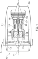
- FIG. 1 shows an example of an aircraft engine, in this case a gas turbine engine.
- the engine is generally indicated at 10.
- the engine 10 comprises, in axial flow series, an air intake 12, a fan 13 for propulsion, an intermediate pressure compressor 14, a high-pressure compressor 15, combustion equipment 16, a high-pressure turbine 17, an intermediate pressure turbine 18, a low-pressure turbine 19 and an exhaust nozzle 20.
- a nacelle 21 generally surrounds the engine 10 and defines both the intake 12 and the exhaust nozzle 20.
- the fan casing has a generally cylindrical form, and as such has a central axis 11 running through the centre of the cylindrical form.
- a forward end of the fan casing is the end nearest to the air intake 12, and the rearward end of the fan casing is the end nearest to the exhaust nozzle 20.
- the central axis 11 of the fan casing 100 will generally overlap, and be coincident with, the rotational axis of the engine it is fitted to.
- the engine 10 shown in figure 1 works in the conventional manner for a gas turbine engine, so that air entering the intake 12 is accelerated by the fan 13 to produce two air flows: a first air flow into the intermediate pressure compressor 14 and a second air flow which passes through a bypass duct 22 to provide propulsive thrust.
- the intermediate pressure compressor 14 compresses the air flow directed into it before delivering that air to the high pressure compressor 15 where further compression takes place.
- the compressed air exhausted from the high-pressure compressor 15 is directed into the combustion equipment 16 where it is mixed with fuel and the mixture combusted.
- the resultant hot combustion products then expand through, and thereby drive the high, intermediate, and low-pressure turbines 17, 18, 19 before being exhausted through the exhaust nozzle 20 to provide additional propulsive thrust.
- the high 17, intermediate 18 and low 19 pressure turbines drive respectively the high pressure compressor 15, intermediate pressure compressor 14 and fan 13, each by suitable interconnecting shaft.
- engines to which the present invention may be applied may have alternative configurations.
- such engines may have an alternative number of interconnecting shafts (e.g. two) and/or an alternative number of compressors and/or turbines.
- the engine may comprise a gearbox provided in the drive train from a turbine to a compressor and/or fan.
- Further engines may be electric, and as such the gas turbine components are replaced with an electric motor, as illustrated in figure 2 .
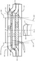
- Figure 3 is a sectional view of the region indicated by box A in figures 1 & 2 , and shows the section of the engine around the fan 13, which includes the sections at the top and bottom of the nacelle 21, including sections of the fan casing 100. If a fragment of a fan blade detaches during operation, then it will travel towards the surrounding region, contacting the impact region 104, of the fan casing 100. Within the impact region 104 is a main impact region 106 adjacent to the fan, which is designed to absorb the released blade fragment impact energy ensuring that any debris is safely contained within the fan casing 100.
- the main impact region 106 is schematically shown as being slightly thicker than the neighbouring regions of the fan containment casing 100. For composite containment casings this is physically accurate, as the main impact region 106 comprises more material than the regions surrounding it in order to better contain and absorb energy from fan blade fragments.
- the nature of the impact region surrounding the main impact region can comprise various configurations as known in the art.
- This invention is concerned with the configuration of the main impact region, as defined below.
- Figure 4 shows a similar sectional view of an engine 10 to that of figure 3 .
- figure 4 shows two fan blades 400 of the fan 13.
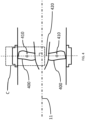
- Each of the fan blades 400 has a centre of gravity (CoG) 410, which, within manufacturing tolerances of the blades, is in the same relative position for each of the fan blades 400.
- CoG centre of gravity
- the central axis 11 is normal to the blade CoG plane 420 on which all of the CoGs of the fan blades 400 lie.
- the axial extent of the main impact region 106 is defined as shown in figure 5 , which shows the area highlighted by the box C in Figure 4 .
- the central axis 11 and the blade CoG plane 420 are shown.
- the fan blade CoG plane passes through the main impact region 106 of the fan casing 100.
- a forward limiting plane 430, and a rearward limiting plane 440 are indicated.
- the forward limiting plane 430 is a conical plane, with the vertex of the cone being at the point where the forward limiting plane 430 intersects the central axis 11 of the fan casing 100 (which is the same point as where the blade CoG plane 420 intersects the central axis), and the sides of the cone being angled forwards, towards the section of the fan casing 100 nearest to the intake 12 of the engine 10, by an angle ⁇ 1 from the blade CoG plane 420.
- the rearward limiting plane 440 is also a conical plane, with the vertex of the cone again being at the point where the rearward limiting plane 440 intersects the central axis 11 of the fan casing 100 (which is the same point where the forward limiting plane 430 intersects the central axis 11 of the fan casing 100), with the sides of the cone angled backwards, towards the section of the fan casing 100 nearest to the exhaust nozzle 20 of the engine 10, by an angle ⁇ 2 from the blade CoG plane 420.
- the minimum angle ⁇ 1 between the forward limiting plane 430 and the blade CoG plane 420 equals 8 degrees
- the minimum angle ⁇ 2 between the rearward limiting plane 440 and the blade CoG plane 420 equals 9 degrees.
- the axial extent of the main impact region can be adjusted for different engine designs, depending on at least necessary angular coverage and desired fan casing 100 mass.
- the point where the forward limiting plane 430 intersects the fan casing interior surface 110 marks the position of a first boundary plane 450 for that section of the fan casing.
- the first boundary plane 450 is a flat plane normal to the central axis 11 of the casing 100.
- the point where the rearward limiting plane 440 intersects the fan casing interior surface 110 marks the position of a second boundary plane 460, which is also a flat plane normal to the central axis 11 of the casing 100.
- the minimum axial extent of the main impact region 106 is from the first boundary plane 450 to the second boundary plane 460.
- the main impact region encompasses the expected trajectories, based on ⁇ 1 , ⁇ 2 , and the CoG of the fan blades, of any blade fragments that may inadvertently be released from the fan 13.
- the fan casing can have various configurations.
- the fan casing sections are shown as having parallel fan casing interior surfaces, such as would be the case for a substantially cylindrical fan case. It will however be clear to the skilled person that the fan casing interior surfaces may be divergent, convergent, parallel, or some combination of the three, depending on the design of the fan case. Regardless, the definitions used to determine the minimum axial extent of the main impact region are still applicable.
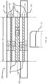
- Figure 6 shows a sectional view of the region D of figure 5 for a first example embodiment of the present invention, specifically how the materials used to make the fan casing 100 in the main impact region 106 can be arranged to provide improved debris containment whilst also being lightweight in design.
- the fan casing 100 generally has an interior abradable liner adjacent to the fan as is known in the prior art. For purposes of clarity, the abradable lining is not shown in the examples, and does not count towards the arrangements of materials described herein.
- Figures 6 to 16 also show the neutral axis, which is a ring around the fan casing which marks the boundary between the radially inner 50% of the main impact region and the radially outer 50% of the main impact region, the radial extent of the main impact region being bounded by the fan casing interior surface 110 and fan casing exterior surface 120 in figures 6 to 16 .
- the fan casing 100 is shown as having five layers of two types: carbon-fibre reinforced polymer (CFRP) layers 210 (shown as solid shapes), and glass-fibre reinforced polymer (GFRP) layers 310 (shown as shapes with diagonal lines through them). Other examples have different numbers of layers. Whist it is possible for the thickness of each layer to vary in different locations, for the purposes of this invention, the thicknesses of the CFRP layers and the GFRP layers are constant within the main impact region 106. As such, the part of each layer within the bounds of the main impact region is referred to as a "block", such that each block's thickness does not vary within the axial extent of the main impact region.
- the CFRP blocks 200 alternate with the GFRP blocks 300, such that each GFRP block is sandwiched between two CFRP blocks.
- the main impact region 106 is shown as extending axially between the first boundary plane 450 and the second boundary plane 460, even though the CFRP layers 210 and GFRP layers 310 extend axially beyond the first boundary plane 450 and second boundary plane 460.
- the first boundary plane 450 and second boundary plane 460 mark the minimum axial extent of the main impact region 106, meaning it is perfectly acceptable for the CFRP layers 210 and/or the GFRP layers 310 to extend axially beyond the first boundary plane 450 and/or second boundary plane 460 whilst the CFRP blocks 200 and GFRP block 300 still fulfil the requirements of the invention.
- the GFRP layers 310 which comprise both the GFRP blocks 300 (i.e. the sections of each of the GFRP layers within the main impact region) and the sections of GFRP layers outside of the main impact region, are shown as terminating just outside of the main impact region, whereas the CFRP layers 210, which comprise both the CFRP blocks 200 (i.e. the sections of each of the CFRP layers within the main impact region) and the sections of CFRP layers outside of the main impact region, continue on axially forward and rearward after the GFRP layers have terminated, and therefore are brought into contact with each other outside of the main impact region 106.
- the CFRP blocks 200 are part of the outermost layers, i.e. the block closest to the fan casing interior surface 110, and the block closest to the fan casing exterior surface 120, as shown in the figures.
- the flexural modulus of the laminate is enhanced compared with an impact region consisting entirely of CFRP blocks.
- the CFRP blocks 200 are positioned at the outermost layers where high strength is required, whilst the GFRP blocks 300 have been divided into blocks having thicknesses G1, G2 which are not the same. Such an arrangement can improve energy dispersion within the impact region.
- the CFRP blocks have thicknesses C1, C2, C3 which are all the same.
- the blocks consist of 2D interwoven ply tapes, wherein the tapes making up the blocks are laid up on top of one another with spaces between the tapes making up a sublayer, and the tapes of one sublayer being laid at an angle compared to tapes of a different sublayer.
- An example of such a construction method can be found in United Kingdom patent GB 2485215 B , herein incorporated by reference. The skilled person will understand that this is not an essential feature, and that any suitable method for constructing the blocks 200, 300 can be used. Equally, the blocks themselves are not interlocked, but rather they are separate and laid on top of one another, prior to curing.
- the plies used to make up the CFRP blocks 200 and GFRP blocks 300 are made using the same resin, so that the once the CFRP and GFRP blocks have been arranged, they can be cured as one in a single curing process.
- Figures 7 to 16 are sectional views of further different examples of embodiments of the present invention, which are shown with reference to the region indicated by box D in Figure 5 .
- Figure 7 shows an example of an alternative embodiment, which varies from the embodiment of figure 6 in that the CFRP blocks 200 do not all have the same thickness.
- the CFRP block nearest the fan casing interior surface 110 has a first thickness C1 which is less than the thicknesses C2, C3 of the remaining two CFRP blocks.
- the GFRP blocks 300 are again not of the same thickness.
- Figure 8 shows an example of an alternative embodiment where the GFRP has been further split, so that in this example it comprises four blocks 300.
- the GFRP blocks have been distributed symmetrically around the impact region's neutral axis 350.
- the CFRP blocks 200 do not all have the same thickness.
- the middle CFRP block has a thickness C3 greater than the thicknesses C1, C2, C4, C5 of the remaining CFRP blocks.
- the GFRP blocks 300 do also not all have the same thickness, the thicknesses G2, G3 of the GFRP blocks nearest the neutral axis 350 being greater than the thicknesses G1, G4 of the GFRP blocks furthest from the neutral axis.
- the CFRP blocks 200 and GFRP blocks 300 are once again arranged symmetrically about the neutral axis 350, but in this example it is a GFRP block that has the neutral axis passing through it. Having a GFRP block enveloping the neutral axis 350 amplifies the flexural modulus of the main impact region 106, further improving its impact capability.
- both the CFRP blocks 200 and the GFRP blocks 300 are made up of blocks not all having the same thickness.
- the thinnest CFRP blocks are nearest to the neutral axis, and the thickest CFRP blocks are furthest from the neutral axis.
- the thinnest GFRP block is nearest the neutral axis (in this example, enveloping the neutral axis)
- the thickest GFRP blocks are the GFRP blocks furthest from the neutral axis.
- Figure 10 shows an example of an embodiment where the GFRP block enveloping the neutral axis 350 is the thickest of the GFRP blocks in the main impact region 106.
- the CFRP blocks 200 and GFRP blocks 300 are not all of the same thickness, and are arranged symmetrically around the neutral axis 350.
- GFRP blocks 300 having thicknesses G1, G2, G3, G4 and G5, where the GFRP block enveloping the neutral axis 350 has a thickness G3 which is greater than the thicknesses G1, G5 of each of the GFRP blocks furthest from the neutral axis, and greater than the thicknesses G2, G4 of each of the GFRP blocks intermediate between the GFRP block enveloping the neutral axis and the GFRP blocks furthest from the neutral axis.
- CFRP blocks 200 having thicknesses C1, C2, C3, C4, C5 and C6, the CFRP blocks closest to the neutral axis having thicknesses C3, C4 which are equal to the thicknesses C1, C6 of the CFRP blocks of the outermost layers, i.e. the layer closest to the fan casing interior surface 110 and the layer closest to the fan casing exterior surface 120 as seen in figure 10 .
- Figure 11 shows an example of an embodiment where the GFRP blocks which are furthest from the neutral axis 350 are the thinnest of the GFRP blocks within the main impact region 106.
- the GFRP block enveloping the neutral axis 350 has a thickness G2 which is greater than the thicknesses G1 and G3 of the GFRP blocks which are furthest from the neutral axis 350 within the impact region.
- GFRP blocks could be incorporated into the impact region, but in this embodiment they would be closer to the neutral axis, and thicker than, the GFRP blocks furthest from the neutral axis, so that the GFRP blocks furthest from the neutral axis would continue to be the thinnest of the plurality of GFRP blocks.
- Figure 12 shows an example of an embodiment sharing many of the same features as Figure 11 , in that the GFRP blocks which are furthest from the neutral axis 350 are the thinnest of the GFRP blocks within the main impact region 106, the GFRP block enveloping the neutral axis 350 has a thickness G2 which is greater than the thicknesses G1 and G3 of the GFRP blocks which are furthest from the neutral axis 350 within the impact region, and the CFRP blocks 200 and GFRP blocks 300 are arranged symmetrically around the neutral axis 350, with the thickest of the GFRP blocks 200 enveloping the neutral axis.
- the CFRP blocks furthest from the neutral axis 350 are the thinnest of the CFRP blocks 200 included within the main impact region 106.
- Figure 13 shows an example of an embodiment where the GFRP blocks which are furthest from the neutral axis 350 are the thinnest of the GFRP blocks within the main impact region 106, the GFRP block enveloping the neutral axis 350 has a thickness G2 which is greater than the thicknesses G1 and G3 of the GFRP blocks which are furthest from the neutral axis 350 within the impact region, and the CFRP blocks 200 and GFRP blocks 300 are arranged symmetrically around the neutral axis 350, with the thickest of the GFRP blocks 200 enveloping the neutral axis.
- the thicknesses G1, G3 of the GFRP blocks furthest from the neutral axis 350 are the same as the thicknesses C1, C4 of the CFRP blocks furthest from the neutral axis within the main impact region 106.
- Figure 14 shows an example of a further embodiment where the GFRP blocks which are furthest from the neutral axis 350 are the thinnest of the GFRP blocks within the main impact region 106, the GFRP block enveloping the neutral axis 350 has a thickness G2 which is greater than the thicknesses G1 and G3 of the GFRP blocks which are furthest from the neutral axis 350 within the impact region, and the CFRP blocks 200 and GFRP blocks 300 are arranged symmetrically around the neutral axis 350, with the thickest of the GFRP blocks 200 enveloping the neutral axis.
- the CFRP blocks sandwiching the thickest of the plurality of GFRP blocks have thicknesses C2, C3 equal to the thickness G2 of the thickest of the plurality of GFRP blocks.
- the thickest of the GFRP blocks in the main impact region 106 has a thickness G2.
- the CFRP blocks sandwiching it have thicknesses C2, C3 which are equal to each other and G2.
- FIG 15 shows an example of a further embodiment where each of the CFRP blocks 200 are equal in thickness.
- the CFRP blocks 200 have thicknesses C1, C2, C3, C4 equal to each other and the thickness G2 of the thickest GFRP block, but each of the CFRP blocks having the same thickness as the thickest of the GFRP blocks is not an essential feature of this embodiment.
- the CFRP blocks and the GFRP blocks are shown as being symmetrically arranged around the neutral axis, but this is also not an essential feature of this embodiment.
- Figure 16 shows an example of a further embodiment where there are three GFRP blocks 300.
- the GFRP blocks furthest from the neutral axis 350 have thicknesses G1, G3 which are equal to each other, and half as thick as the thickness G2 of the GFRP block nearest the neutral axis 350, which in this example is bisected by the neutral axis, and therefore centrally located within the radial extent of the main impact region 106 between the fan casing interior surface 110 and fan casing exterior surface 120.
- the arrangement of the CFRP blocks 200 and the GFRP blocks 300 are such that they are symmetrical about the neutral axis 350.
- the CFRP blocks at the bounds of the region provide high strength regions to prevent any debris that impacts on the case from exiting the case; the GFRP blocks provide regions of lower stiffness but higher deflection; and the central GFRP block enveloping the neutral axis 350 amplifies the flexural modulus of the impact region, leading to a region of fan casing with an improved energy dispersion rate for enhanced impact resistance.
Landscapes
- Engineering & Computer Science (AREA)
- Mechanical Engineering (AREA)
- General Engineering & Computer Science (AREA)
- Chemical & Material Sciences (AREA)
- Materials Engineering (AREA)
- Structures Of Non-Positive Displacement Pumps (AREA)
Abstract
Description
- The present invention provides a fan casing for an aircraft engine.
- One of the important functions of the casing around an aircraft engine is to absorb the impact of all or part of a fan blade in the event of fracture or damage, for example caused by a bird being ingested into the engine. To fulfil this function, the casing must be able to absorb large amounts of energy so as to prevent any debris, such as blade fragments, from exiting the engine. However, the design of the fan casing is also constrained by weight, as the heavier a fan casing is, the more costly it is to fly. Therefore when it comes to fragment capture, the goal is to provide the best safety performance with the lightest possible hardware.
- The present invention provides a fan casing which improves upon designs of the prior art, providing improved debris retention properties whilst also being lightweight in design.
- The present invention concerns a fan casing for a gas turbine engine as set out in claim 1, an engine as set out in
claim 14, and an aircraft comprising such a fan casing as set out inclaim 15. - According to a first aspect there is provided a fan casing for an engine having a fan with fan blades that each have a centre of gravity (CoG) that lies on a fan blade CoG plane, the fan casing having a central axis, a forward end, a rearward end, and comprising a main impact region, the main impact region having an axial extent with respect to the central axis of the fan casing such that, when installed on an engine with a fan having fan blades, the minimum axial extent of the main impact region is from a first boundary plane to a second boundary plane, wherein the first boundary plane is a plane normal to the central axis of the fan casing extending from the points where a forward limiting plane intersects a fan casing interior surface, the forward limiting plane being a conical plane with the base of the cone being the point where the forward limiting plane intersects the central axis of the fan casing, with the cone of the forward limiting plane having an angle θ1 to the fan blade CoG plane, where the angle θ1 equals 8 degrees, and wherein the second boundary plane is a plane also normal to the central axis of the fan casing extending from the points where a rearward limiting plane intersects a fan casing interior surface, the rearward limiting plane being a conical plane with the base of the cone being the point where the rearward limiting plane and the forward limiting plane intersect the central axis of the fan casing, with the cone of the rearward limiting plane having an angle θ2 to the fan blade CoG plane, where the angle θ2 equals 9 degrees;
- the main impact region comprising:
- at least three carbon-fibre reinforced polymer (CFRP) blocks having a constant thickness throughout the axial extent of the main impact region when viewed in cross-section;
- a first plurality of glass-fibre reinforced polymer (GFRP) blocks having a constant thickness throughout the axial extent of the main impact region when viewed in cross-section; and
- a neutral axis extending across the axial extent of the main impact region, the neutral axis being positioned at half the total depth of the main impact region, wherein the total depth of the main impact region is equal to the sum of the thicknesses of the CFRP blocks and GFRP blocks within the main impact region;
- wherein, each of the plurality of GFRP blocks is positioned between two CFRP blocks; and the thickness of at least one of the plurality of GFRP blocks is different to the thickness of another of the plurality of GFRP blocks.
- Having CFRP blocks at the bounds of the region provides high strength blocks which prevent any debris that impacts on the case from exiting the case; the different thicknesses of GFRP blocks within the region provide lower stiffnesses but allow increased deflection when impacted by debris. A fan case having a combination of such features can exhibit improved energy dispersion within the impact region.
- The arrangement of the thicknesses of the GFRP and CFRP blocks in the fan casing may be symmetrical about the neutral axis of the main impact region.
- The neutral axis of the fan casing may pass through one of the GFRP blocks. Having a central GFRP block enveloping the neutral axis can amplify the flexural modulus of the impact region, leading to a region of fan casing with an improved energy dispersion rate for enhanced impact resistance.
- The main impact region of the fan casing may consist of four CFRP blocks and three GFRP blocks.
- The thickest of the plurality of GFRP blocks of the fan casing may be bisected by the neutral axis.
- The GFRP blocks furthest from the neutral axis of the fan casing may be the thinnest of the plurality of GFRP blocks.
- The CFRP blocks sandwiching the thickest of the plurality of GFRP blocks of the fan casing may be the same thickness as the thickest of the plurality of GFRP blocks.
- The GFRP blocks furthest from the neutral axis of the fan casing may be half as thick as the GFRP block bisected by the neutral axis.
- The CFRP blocks of the fan casing may be the same thickness.
- The thickness of at least one of the at least three CFRP blocks of the fan casing may be different to the thickness of another of the at least three CFRP blocks.
- The CFRP blocks furthest from the neutral axis of the fan casing may be the thinnest of the CFRP blocks.
- The GFRP blocks adjacent to the CFRP blocks furthest from the neutral axis of the main impact region of the fan casing may be the same thickness as the CFRP blocks furthest from the neutral axis of the main impact region.
- The CFRP blocks and/or the GFRP blocks of the fan casing may be composed of 2D interwoven ply tapes.
- According to a second aspect there is provided an engine comprising a fan casing according to the first aspect, wherein the fan casing is positioned such that the fan blade centre of gravity (CoG) plane of the fan of the engine passes through the main impact region of the fan casing.
- According to a third aspect, there is provided an aircraft comprising an engine according to the second aspect.
- The skilled person will appreciate that except where mutually exclusive, a feature described in relation to any one of the above aspects may be applied mutatis mutandis to any other aspect. Furthermore except where mutually exclusive any feature described herein may be applied to any aspect and/or combined with any other feature described herein.
- Embodiments will now be described by way of example only, with reference to the Figures, in which:
-
Figure 1 is a sectional side view of a gas turbine engine; -
Figure 2 is a sectional side view of an electric aircraft engine; -
Figure 3 is a sectional view of region A outlined infigures 1 and2 ; -
Figure 4 is a second sectional view of region A outlined infigures 1 and2 ; -
Figure 5 is a sectional view of region C outlined infigure 4 ; -
Figure 6 is a sectional view of region B outlined infigure 3 showing a first embodiment of the present invention; -
Figure 7 is a sectional view of region B outlined infigure 3 showing a second embodiment of the present invention; -
Figure 8 is a sectional view of region B outlined infigure 3 showing a third embodiment of the present invention; -
Figure 9 is a sectional view of region B outlined infigure 3 showing a fourth embodiment of the present invention; -
Figure 10 is a sectional view of region B outlined infigure 3 showing a fifth embodiment of the present invention; -
Figure 11 is a sectional view of region B outlined infigure 3 showing a sixth embodiment of the present invention; -
Figure 12 is a sectional view of region B outlined infigure 3 showing a seventh embodiment of the present invention; -
Figure 13 is a sectional view of region B outlined infigure 3 showing an eighth embodiment of the present invention; -
Figure 14 is a sectional view of region B outlined infigure 3 showing a ninth embodiment of the present invention; -
Figure 15 is a sectional view of region B outlined infigure 3 showing a tenth embodiment of the present invention; and -
Figure 16 is a sectional view of region B outlined infigure 3 showing an eleventh embodiment of the present invention. - Aspects and embodiments of the present invention will now be discussed with reference to the accompanying figures. Further aspects and embodiments will be apparent to those skilled in the art.
-
Figure 1 shows an example of an aircraft engine, in this case a gas turbine engine. The engine is generally indicated at 10. Theengine 10 comprises, in axial flow series, anair intake 12, afan 13 for propulsion, anintermediate pressure compressor 14, a high-pressure compressor 15,combustion equipment 16, a high-pressure turbine 17, anintermediate pressure turbine 18, a low-pressure turbine 19 and anexhaust nozzle 20. Anacelle 21 generally surrounds theengine 10 and defines both theintake 12 and theexhaust nozzle 20. Within thenacelle 21 adjacent to thefan 13 there is a section of fan casing 100 (seefigure 3 ). The fan casing has a generally cylindrical form, and as such has acentral axis 11 running through the centre of the cylindrical form. When installed on anengine 10 as part of thenacelle 21, a forward end of the fan casing is the end nearest to theair intake 12, and the rearward end of the fan casing is the end nearest to theexhaust nozzle 20. When installed on anengine 10 as part of thenacelle 21, thecentral axis 11 of thefan casing 100 will generally overlap, and be coincident with, the rotational axis of the engine it is fitted to. - The
engine 10 shown infigure 1 works in the conventional manner for a gas turbine engine, so that air entering theintake 12 is accelerated by thefan 13 to produce two air flows: a first air flow into theintermediate pressure compressor 14 and a second air flow which passes through abypass duct 22 to provide propulsive thrust. Theintermediate pressure compressor 14 compresses the air flow directed into it before delivering that air to thehigh pressure compressor 15 where further compression takes place. - The compressed air exhausted from the high-
pressure compressor 15 is directed into thecombustion equipment 16 where it is mixed with fuel and the mixture combusted. The resultant hot combustion products then expand through, and thereby drive the high, intermediate, and low-pressure turbines exhaust nozzle 20 to provide additional propulsive thrust. The high 17, intermediate 18 and low 19 pressure turbines drive respectively thehigh pressure compressor 15,intermediate pressure compressor 14 andfan 13, each by suitable interconnecting shaft. - Other engines to which the present invention may be applied may have alternative configurations. By way of example such engines may have an alternative number of interconnecting shafts (e.g. two) and/or an alternative number of compressors and/or turbines. Further the engine may comprise a gearbox provided in the drive train from a turbine to a compressor and/or fan. Further engines may be electric, and as such the gas turbine components are replaced with an electric motor, as illustrated in
figure 2 . -
Figure 3 is a sectional view of the region indicated by box A infigures 1 &2 , and shows the section of the engine around thefan 13, which includes the sections at the top and bottom of thenacelle 21, including sections of thefan casing 100. If a fragment of a fan blade detaches during operation, then it will travel towards the surrounding region, contacting theimpact region 104, of thefan casing 100. Within theimpact region 104 is amain impact region 106 adjacent to the fan, which is designed to absorb the released blade fragment impact energy ensuring that any debris is safely contained within thefan casing 100. Infigure 3 , themain impact region 106 is schematically shown as being slightly thicker than the neighbouring regions of thefan containment casing 100. For composite containment casings this is physically accurate, as themain impact region 106 comprises more material than the regions surrounding it in order to better contain and absorb energy from fan blade fragments. - For the purposes of this invention, the nature of the impact region surrounding the main impact region can comprise various configurations as known in the art. This invention is concerned with the configuration of the main impact region, as defined below.
-
Figure 4 shows a similar sectional view of anengine 10 to that offigure 3 . For clarity,figure 4 shows twofan blades 400 of thefan 13. Each of thefan blades 400 has a centre of gravity (CoG) 410, which, within manufacturing tolerances of the blades, is in the same relative position for each of thefan blades 400. As the fan blades are all mounted around thefan 13 in a similar manner, the fan blade CoGs will all lie on ablade CoG plane 420. Because the fan is designed to rotate around a rotational axis, which is coincident with thecentral axis 11 of thefan casing 100 when the fan casing is installed upon theengine 10, thecentral axis 11 is normal to theblade CoG plane 420 on which all of the CoGs of thefan blades 400 lie. - The axial extent of the
main impact region 106 is defined as shown infigure 5 , which shows the area highlighted by the box C inFigure 4 . Thecentral axis 11 and theblade CoG plane 420 are shown. As can be seen, the fan blade CoG plane passes through themain impact region 106 of thefan casing 100. A forward limitingplane 430, and a rearward limitingplane 440 are indicated. Theforward limiting plane 430 is a conical plane, with the vertex of the cone being at the point where theforward limiting plane 430 intersects thecentral axis 11 of the fan casing 100 (which is the same point as where theblade CoG plane 420 intersects the central axis), and the sides of the cone being angled forwards, towards the section of thefan casing 100 nearest to theintake 12 of theengine 10, by an angle θ1 from theblade CoG plane 420. The rearward limitingplane 440 is also a conical plane, with the vertex of the cone again being at the point where the rearward limitingplane 440 intersects thecentral axis 11 of the fan casing 100 (which is the same point where theforward limiting plane 430 intersects thecentral axis 11 of the fan casing 100), with the sides of the cone angled backwards, towards the section of thefan casing 100 nearest to theexhaust nozzle 20 of theengine 10, by an angle θ2 from theblade CoG plane 420. In this exemplary embodiment, the minimum angle θ1 between the forward limitingplane 430 and theblade CoG plane 420, equals 8 degrees, while the minimum angle θ2 between the rearward limitingplane 440 and theblade CoG plane 420, equals 9 degrees. It will be understood that the axial extent of the main impact region can be adjusted for different engine designs, depending on at least necessary angular coverage and desiredfan casing 100 mass. For each section of the fan casing, the point where theforward limiting plane 430 intersects the fan casinginterior surface 110 marks the position of afirst boundary plane 450 for that section of the fan casing. Thefirst boundary plane 450 is a flat plane normal to thecentral axis 11 of thecasing 100. Equally, the point where the rearward limitingplane 440 intersects the fan casinginterior surface 110 marks the position of asecond boundary plane 460, which is also a flat plane normal to thecentral axis 11 of thecasing 100. For a given section of the fan casing, the minimum axial extent of themain impact region 106 is from thefirst boundary plane 450 to thesecond boundary plane 460. In this way the main impact region encompasses the expected trajectories, based on θ1, θ2, and the CoG of the fan blades, of any blade fragments that may inadvertently be released from thefan 13. - It will be understood by the skilled person that the fan casing can have various configurations. For simplicity, in the figures the fan casing sections are shown as having parallel fan casing interior surfaces, such as would be the case for a substantially cylindrical fan case. It will however be clear to the skilled person that the fan casing interior surfaces may be divergent, convergent, parallel, or some combination of the three, depending on the design of the fan case. Regardless, the definitions used to determine the minimum axial extent of the main impact region are still applicable.
-
Figure 6 shows a sectional view of the region D offigure 5 for a first example embodiment of the present invention, specifically how the materials used to make thefan casing 100 in themain impact region 106 can be arranged to provide improved debris containment whilst also being lightweight in design. It will be understood that whilst box D and the examples shown are with relation to the top of the fan casing section, the same design will apply to the full 360° circumference of the fan casing. Thefan casing 100 generally has an interior abradable liner adjacent to the fan as is known in the prior art. For purposes of clarity, the abradable lining is not shown in the examples, and does not count towards the arrangements of materials described herein. -
Figures 6 to 16 also show the neutral axis, which is a ring around the fan casing which marks the boundary between the radially inner 50% of the main impact region and the radially outer 50% of the main impact region, the radial extent of the main impact region being bounded by the fan casinginterior surface 110 and fan casingexterior surface 120 infigures 6 to 16 . - In the example of
figure 6 , thefan casing 100 is shown as having five layers of two types: carbon-fibre reinforced polymer (CFRP) layers 210 (shown as solid shapes), and glass-fibre reinforced polymer (GFRP) layers 310 (shown as shapes with diagonal lines through them). Other examples have different numbers of layers. Whist it is possible for the thickness of each layer to vary in different locations, for the purposes of this invention, the thicknesses of the CFRP layers and the GFRP layers are constant within themain impact region 106. As such, the part of each layer within the bounds of the main impact region is referred to as a "block", such that each block's thickness does not vary within the axial extent of the main impact region. The CFRP blocks 200 alternate with the GFRP blocks 300, such that each GFRP block is sandwiched between two CFRP blocks. Infigure 6 , themain impact region 106 is shown as extending axially between thefirst boundary plane 450 and thesecond boundary plane 460, even though the CFRP layers 210 andGFRP layers 310 extend axially beyond thefirst boundary plane 450 andsecond boundary plane 460. As explained above, thefirst boundary plane 450 andsecond boundary plane 460 mark the minimum axial extent of themain impact region 106, meaning it is perfectly acceptable for the CFRP layers 210 and/or the GFRP layers 310 to extend axially beyond thefirst boundary plane 450 and/orsecond boundary plane 460 whilst the CFRP blocks 200 and GFRP block 300 still fulfil the requirements of the invention. - In the embodiment of
Figure 6 , the GFRP layers 310, which comprise both the GFRP blocks 300 (i.e. the sections of each of the GFRP layers within the main impact region) and the sections of GFRP layers outside of the main impact region, are shown as terminating just outside of the main impact region, whereas the CFRP layers 210, which comprise both the CFRP blocks 200 (i.e. the sections of each of the CFRP layers within the main impact region) and the sections of CFRP layers outside of the main impact region, continue on axially forward and rearward after the GFRP layers have terminated, and therefore are brought into contact with each other outside of themain impact region 106. Infigures 7 to 16 illustrating further example embodiments of the invention, the parts of the CRFP layers 210 andGFRP layers 310 outside of themain impact region 106 have been omitted for clarity, as the invention is only concerned with the arrangement of the blocks 200,300 within themain impact region 106. - In the example of
figure 6 , the CFRP blocks 200 are part of the outermost layers, i.e. the block closest to the fan casinginterior surface 110, and the block closest to the fan casingexterior surface 120, as shown in the figures. By combining the greater ductility of the GFRP blocks with the high strength and stiffness of the CFRP blocks, the flexural modulus of the laminate is enhanced compared with an impact region consisting entirely of CFRP blocks. Specifically, infigure 6 , the CFRP blocks 200 are positioned at the outermost layers where high strength is required, whilst the GFRP blocks 300 have been divided into blocks having thicknesses G1, G2 which are not the same. Such an arrangement can improve energy dispersion within the impact region. Infigure 6 , the CFRP blocks have thicknesses C1, C2, C3 which are all the same. - In the example embodiments described herein, the blocks consist of 2D interwoven ply tapes, wherein the tapes making up the blocks are laid up on top of one another with spaces between the tapes making up a sublayer, and the tapes of one sublayer being laid at an angle compared to tapes of a different sublayer. An example of such a construction method can be found in
United Kingdom patent GB 2485215 B blocks GFRP blocks 300 are made using the same resin, so that the once the CFRP and GFRP blocks have been arranged, they can be cured as one in a single curing process. -
Figures 7 to 16 are sectional views of further different examples of embodiments of the present invention, which are shown with reference to the region indicated by box D inFigure 5 . -
Figure 7 shows an example of an alternative embodiment, which varies from the embodiment offigure 6 in that the CFRP blocks 200 do not all have the same thickness. In the example shown, the CFRP block nearest the fan casinginterior surface 110 has a first thickness C1 which is less than the thicknesses C2, C3 of the remaining two CFRP blocks. The GFRP blocks 300 are again not of the same thickness. -
Figure 8 shows an example of an alternative embodiment where the GFRP has been further split, so that in this example it comprises fourblocks 300. The GFRP blocks have been distributed symmetrically around the impact region'sneutral axis 350. The CFRP blocks 200 do not all have the same thickness. In this case the middle CFRP block has a thickness C3 greater than the thicknesses C1, C2, C4, C5 of the remaining CFRP blocks. As with the example ofFigures 6 and7 , the GFRP blocks 300 do also not all have the same thickness, the thicknesses G2, G3 of the GFRP blocks nearest theneutral axis 350 being greater than the thicknesses G1, G4 of the GFRP blocks furthest from the neutral axis. - In the exemplary embodiment of
figure 9 , the CFRP blocks 200 andGFRP blocks 300 are once again arranged symmetrically about theneutral axis 350, but in this example it is a GFRP block that has the neutral axis passing through it. Having a GFRP block enveloping theneutral axis 350 amplifies the flexural modulus of themain impact region 106, further improving its impact capability. As with the examples offigures 7 and8 , both the CFRP blocks 200 and the GFRP blocks 300 are made up of blocks not all having the same thickness. In this example, the thinnest CFRP blocks are nearest to the neutral axis, and the thickest CFRP blocks are furthest from the neutral axis. Also, the thinnest GFRP block is nearest the neutral axis (in this example, enveloping the neutral axis), whereas the thickest GFRP blocks are the GFRP blocks furthest from the neutral axis. -
Figure 10 shows an example of an embodiment where the GFRP block enveloping theneutral axis 350 is the thickest of the GFRP blocks in themain impact region 106. As with the examples offigures 7 ,8 , and9 , the CFRP blocks 200 andGFRP blocks 300 are not all of the same thickness, and are arranged symmetrically around theneutral axis 350. In the example offigure 10 , there are fiveGFRP blocks 300 having thicknesses G1, G2, G3, G4 and G5, where the GFRP block enveloping theneutral axis 350 has a thickness G3 which is greater than the thicknesses G1, G5 of each of the GFRP blocks furthest from the neutral axis, and greater than the thicknesses G2, G4 of each of the GFRP blocks intermediate between the GFRP block enveloping the neutral axis and the GFRP blocks furthest from the neutral axis. There are sixCFRP blocks 200 having thicknesses C1, C2, C3, C4, C5 and C6, the CFRP blocks closest to the neutral axis having thicknesses C3, C4 which are equal to the thicknesses C1, C6 of the CFRP blocks of the outermost layers, i.e. the layer closest to the fan casinginterior surface 110 and the layer closest to the fan casingexterior surface 120 as seen infigure 10 . -
Figure 11 shows an example of an embodiment where the GFRP blocks which are furthest from theneutral axis 350 are the thinnest of the GFRP blocks within themain impact region 106. The GFRP block enveloping theneutral axis 350 has a thickness G2 which is greater than the thicknesses G1 and G3 of the GFRP blocks which are furthest from theneutral axis 350 within the impact region. In this embodiment there are no further GFRP blocks within the impact region, and as such the GFRP blocks furthest from the neutral axis are the thinnest of the plurality of GFRP blocks. Equally, additional GFRP blocks could be incorporated into the impact region, but in this embodiment they would be closer to the neutral axis, and thicker than, the GFRP blocks furthest from the neutral axis, so that the GFRP blocks furthest from the neutral axis would continue to be the thinnest of the plurality of GFRP blocks. -
Figure 12 shows an example of an embodiment sharing many of the same features asFigure 11 , in that the GFRP blocks which are furthest from theneutral axis 350 are the thinnest of the GFRP blocks within themain impact region 106, the GFRP block enveloping theneutral axis 350 has a thickness G2 which is greater than the thicknesses G1 and G3 of the GFRP blocks which are furthest from theneutral axis 350 within the impact region, and the CFRP blocks 200 andGFRP blocks 300 are arranged symmetrically around theneutral axis 350, with the thickest of the GFRP blocks 200 enveloping the neutral axis. In contrast tofigure 11 , in the example embodiment shown infigure 12 the CFRP blocks furthest from theneutral axis 350 are the thinnest of the CFRP blocks 200 included within themain impact region 106. -
Figure 13 shows an example of an embodiment where the GFRP blocks which are furthest from theneutral axis 350 are the thinnest of the GFRP blocks within themain impact region 106, the GFRP block enveloping theneutral axis 350 has a thickness G2 which is greater than the thicknesses G1 and G3 of the GFRP blocks which are furthest from theneutral axis 350 within the impact region, and the CFRP blocks 200 andGFRP blocks 300 are arranged symmetrically around theneutral axis 350, with the thickest of the GFRP blocks 200 enveloping the neutral axis. In addition, the thicknesses G1, G3 of the GFRP blocks furthest from theneutral axis 350 are the same as the thicknesses C1, C4 of the CFRP blocks furthest from the neutral axis within themain impact region 106. -
Figure 14 shows an example of a further embodiment where the GFRP blocks which are furthest from theneutral axis 350 are the thinnest of the GFRP blocks within themain impact region 106, the GFRP block enveloping theneutral axis 350 has a thickness G2 which is greater than the thicknesses G1 and G3 of the GFRP blocks which are furthest from theneutral axis 350 within the impact region, and the CFRP blocks 200 andGFRP blocks 300 are arranged symmetrically around theneutral axis 350, with the thickest of the GFRP blocks 200 enveloping the neutral axis. In addition, the CFRP blocks sandwiching the thickest of the plurality of GFRP blocks have thicknesses C2, C3 equal to the thickness G2 of the thickest of the plurality of GFRP blocks. The thickest of the GFRP blocks in themain impact region 106 has a thickness G2. The CFRP blocks sandwiching it have thicknesses C2, C3 which are equal to each other and G2. -
Figure 15 shows an example of a further embodiment where each of the CFRP blocks 200 are equal in thickness. In this example of the embodiment, the CFRP blocks 200 have thicknesses C1, C2, C3, C4 equal to each other and the thickness G2 of the thickest GFRP block, but each of the CFRP blocks having the same thickness as the thickest of the GFRP blocks is not an essential feature of this embodiment. As withFigure 14 , the CFRP blocks and the GFRP blocks are shown as being symmetrically arranged around the neutral axis, but this is also not an essential feature of this embodiment. -
Figure 16 shows an example of a further embodiment where there are three GFRP blocks 300. The GFRP blocks furthest from theneutral axis 350 have thicknesses G1, G3 which are equal to each other, and half as thick as the thickness G2 of the GFRP block nearest theneutral axis 350, which in this example is bisected by the neutral axis, and therefore centrally located within the radial extent of themain impact region 106 between the fan casinginterior surface 110 and fan casingexterior surface 120. In this example, the arrangement of the CFRP blocks 200 and the GFRP blocks 300 are such that they are symmetrical about theneutral axis 350. There are four CFRP blocks, and their thicknesses C1, C2, C3, C4 are all equal. Having the thickest of the GFRP blocks radially centrally located within the impact region, and additional, GFRP blocks of half the thickness of the thickest GFRP block situated further towards the edges of themain impact region 106, but with CFRP blocks bounding the impact region (i.e. being the blocks nearest to the fan casinginterior surface 110 and fan casing exterior surface 120), has been found to provide improved energy dispersion and debris retention compared to fan casings of the prior art. The CFRP blocks at the bounds of the region provide high strength regions to prevent any debris that impacts on the case from exiting the case; the GFRP blocks provide regions of lower stiffness but higher deflection; and the central GFRP block enveloping theneutral axis 350 amplifies the flexural modulus of the impact region, leading to a region of fan casing with an improved energy dispersion rate for enhanced impact resistance.
Claims (15)
- A fan casing (100) for an engine (10) having a fan (13) with fan blades (400) that each have a centre of gravity (CoG) (410) that lies on a fan blade CoG plane (420), the fan casing having a central axis (11), a forward end, a rearward end, and comprising a main impact region (106), the main impact region having an axial extent with respect to the central axis of the fan casing such that, when installed on an engine with a fan having fan blades, the minimum axial extent of the main impact region is from a first boundary plane (450) to a second boundary plane (460), wherein the first boundary plane (450) is a plane normal to the central axis of the fan casing, extending from the points where a forward limiting plane (430) intersects a fan casing interior surface (110), the forward limiting plane (430) being a conical plane with the vertex of the cone being the point where the fan blade CoG plane (420) intersects the central axis (11) of the fan casing (100), with the cone of the forward limiting plane (430) having an angle θ1 to the fan blade CoG plane (420), where the angle θ1 equals 8 degrees, and wherein the second boundary plane (460) is a plane also normal to the central axis of the fan casing, extending from the points where a rearward limiting plane (440) intersects a fan casing interior surface (110), the rearward limiting plane (440) being a conical plane with the vertex of the cone being the point where the fan blade CoG plane (420) and the forward limiting plane (430) intersect the central axis (11) of the fan casing (100), with the cone of the rearward limiting plane (440) having an angle θ2 to the fan blade CoG plane (420), where the angle θ2 equals 9 degrees;the main impact region (106) comprising:at least three carbon-fibre reinforced polymer (CFRP) blocks (200) having a constant thickness throughout the axial extent of the main impact region when viewed in cross-section;a first plurality of glass-fibre reinforced polymer (GFRP) blocks (300) having a constant thickness throughout the axial extent of the main impact region when viewed in cross-section; anda neutral axis (350) extending across the axial extent of the main impact region, the neutral axis being positioned at half the total depth of the main impact region, wherein the total depth of the main impact region is equal to the sum of the thicknesses of the CFRP blocks (200) and GFRP blocks (300) within the main impact region;wherein, each of the plurality of GFRP blocks is positioned between two CFRP blocks; and
the thickness of at least one of the plurality of GFRP blocks is different to the thickness of another of the plurality of GFRP blocks. - The fan casing of claim 1, wherein the arrangement of the thicknesses of the GFRP blocks (300) and CFRP blocks (200) is symmetrical about the neutral axis (350) of the main impact region.
- The fan casing of claim 1 or 2, wherein the neutral axis (350) passes through one of the GFRP blocks.
- The fan casing of any preceding claim, wherein the main impact region (106) consists of four CFRP blocks (200) and three GFRP blocks (300).
- The fan casing of any preceding claim, wherein the thickest of the plurality of GFRP blocks is bisected by the neutral axis (350).
- The fan casing of any preceding claim, wherein the GFRP blocks furthest from the neutral axis are the thinnest of the plurality of GFRP blocks (300).
- The fan casing of any preceding claim, wherein the CFRP blocks sandwiching the thickest of the plurality of GFRP blocks are the same thickness as the thickest of the plurality of GFRP blocks.
- The fan casing of any preceding claim, wherein the GFRP blocks furthest from the neutral axis (350) are half as thick as the GFRP block bisected by the neutral axis.
- The fan casing of any preceding claim, wherein all the CFRP blocks (200) are of the same thickness.
- The fan casing of any one of claims 1 to 8, wherein the thickness of at least one of the at least three CFRP blocks is different to the thickness of another of the at least three CFRP blocks.
- The fan casing of claim 10, wherein the CFRP blocks furthest from the neutral axis are the thinnest of the CFRP blocks.
- The fan casing of any preceding claim, wherein the GFRP blocks adjacent to the CFRP blocks furthest from the neutral axis (350) of the main impact region (106) are the same thickness as the CFRP blocks furthest from the neutral axis of the main impact region.
- The fan casing of any preceding claim, wherein the CFRP blocks (200) and/or the GFRP blocks (300) are composed of 2D interwoven ply tapes.
- An engine (10) comprising a fan casing (100) according to any preceding claim, wherein the fan casing is positioned such that the fan blade CoG plane (420) of the fan (13) of the engine (10) passes through the main impact region (106) of the fan casing.
- An aircraft comprising an engine (10) according to claim 14.
Applications Claiming Priority (1)
| Application Number | Priority Date | Filing Date | Title |
|---|---|---|---|
| GBGB2200980.7A GB202200980D0 (en) | 2022-01-26 | 2022-01-26 | Impact-resistant fan casing |
Publications (1)
| Publication Number | Publication Date |
|---|---|
| EP4219955A1 true EP4219955A1 (en) | 2023-08-02 |
Family
ID=80507314
Family Applications (1)
| Application Number | Title | Priority Date | Filing Date |
|---|---|---|---|
| EP23150232.9A Pending EP4219955A1 (en) | 2022-01-26 | 2023-01-04 | Impact-resistant fan casing |
Country Status (4)
| Country | Link |
|---|---|
| US (1) | US20230235682A1 (en) |
| EP (1) | EP4219955A1 (en) |
| CN (1) | CN116498578A (en) |
| GB (1) | GB202200980D0 (en) |
Families Citing this family (1)
| Publication number | Priority date | Publication date | Assignee | Title |
|---|---|---|---|---|
| DE102022113843A1 (en) * | 2022-06-01 | 2023-12-07 | Reiner Brach | Engine arrangement for an aircraft and aircraft |
Citations (4)
| Publication number | Priority date | Publication date | Assignee | Title |
|---|---|---|---|---|
| GB2485215B (en) | 2010-11-05 | 2013-12-25 | Gkn Aerospace Services Ltd | Laminate Structure |
| US20180230855A1 (en) * | 2016-09-06 | 2018-08-16 | Rolls-Royce Corporation | Reinforced Fan Containment Case for a Gas Turbine Engine |
| US20190136711A1 (en) * | 2017-11-07 | 2019-05-09 | General Electric Company | Fan casing with annular shell |
| WO2020011617A1 (en) * | 2018-07-13 | 2020-01-16 | Rolls-Royce Plc | Fan blade containment |
-
2022
- 2022-01-26 GB GBGB2200980.7A patent/GB202200980D0/en not_active Ceased
- 2022-12-22 CN CN202211656870.5A patent/CN116498578A/en active Pending
-
2023
- 2023-01-04 EP EP23150232.9A patent/EP4219955A1/en active Pending
- 2023-01-20 US US18/157,392 patent/US20230235682A1/en not_active Abandoned
Patent Citations (4)
| Publication number | Priority date | Publication date | Assignee | Title |
|---|---|---|---|---|
| GB2485215B (en) | 2010-11-05 | 2013-12-25 | Gkn Aerospace Services Ltd | Laminate Structure |
| US20180230855A1 (en) * | 2016-09-06 | 2018-08-16 | Rolls-Royce Corporation | Reinforced Fan Containment Case for a Gas Turbine Engine |
| US20190136711A1 (en) * | 2017-11-07 | 2019-05-09 | General Electric Company | Fan casing with annular shell |
| WO2020011617A1 (en) * | 2018-07-13 | 2020-01-16 | Rolls-Royce Plc | Fan blade containment |
Also Published As
| Publication number | Publication date |
|---|---|
| GB202200980D0 (en) | 2022-03-09 |
| US20230235682A1 (en) | 2023-07-27 |
| CN116498578A (en) | 2023-07-28 |
Similar Documents
| Publication | Publication Date | Title |
|---|---|---|
| CN108457900B (en) | Fan with cooling device | |
| EP2096269B1 (en) | Fan track liner assembly for a gas turbine engine | |
| EP4365409A1 (en) | Gas turbine engine with acoustic spacing of the fan blades and outlet guide vanes | |
| US8403624B2 (en) | Composite containment casings having an integral fragment catcher | |
| US10578115B2 (en) | Composite component with hollow reinforcing pins | |
| US12292017B1 (en) | Gas turbine engine with acoustic spacing of the fan blades and outlet guide vanes | |
| US11396820B2 (en) | Hybridization of fibers of the fibrous reinforcement of a fan blade | |
| GB2557956B (en) | A composite component comprising reinforcing pins | |
| EP3517732A1 (en) | Reinforced composite blade and method of making a blade | |
| US11913346B2 (en) | Multiple layer structure | |
| GB2542893B (en) | A composite component | |
| US20230235682A1 (en) | Impact-resistant fan casing | |
| US20190218920A1 (en) | Blade for a gas turbine engine | |
| EP3023602A1 (en) | Turbine engine assembly and corresponding manufacturing method | |
| US20090151162A1 (en) | Methods for making composite containment casings having an integral fragment catcher | |
| US10385869B2 (en) | Composite component | |
| US20180237120A1 (en) | Aircraft with Under Wing Direct Drive Low Pressure Turbine | |
| US12415333B2 (en) | Containment structure | |
| US12510104B2 (en) | Gas turbine engine with acoustic spacing of the fan blades and outlet guide vanes | |
| GB2567659A (en) | Turbofan engine |
Legal Events
| Date | Code | Title | Description |
|---|---|---|---|
| PUAI | Public reference made under article 153(3) epc to a published international application that has entered the european phase |
Free format text: ORIGINAL CODE: 0009012 |
|
| STAA | Information on the status of an ep patent application or granted ep patent |
Free format text: STATUS: THE APPLICATION HAS BEEN PUBLISHED |
|
| AK | Designated contracting states |
Kind code of ref document: A1 Designated state(s): AL AT BE BG CH CY CZ DE DK EE ES FI FR GB GR HR HU IE IS IT LI LT LU LV MC ME MK MT NL NO PL PT RO RS SE SI SK SM TR |
|
| STAA | Information on the status of an ep patent application or granted ep patent |
Free format text: STATUS: REQUEST FOR EXAMINATION WAS MADE |
|
| 17P | Request for examination filed |
Effective date: 20240115 |
|
| RBV | Designated contracting states (corrected) |
Designated state(s): AL AT BE BG CH CY CZ DE DK EE ES FI FR GB GR HR HU IE IS IT LI LT LU LV MC ME MK MT NL NO PL PT RO RS SE SI SK SM TR |
|
| STAA | Information on the status of an ep patent application or granted ep patent |
Free format text: STATUS: EXAMINATION IS IN PROGRESS |
|
| 17Q | First examination report despatched |
Effective date: 20250507 |