EP4219936A1 - Containerized mobile wind power generation apparatus - Google Patents
Containerized mobile wind power generation apparatus Download PDFInfo
- Publication number
- EP4219936A1 EP4219936A1 EP21872443.3A EP21872443A EP4219936A1 EP 4219936 A1 EP4219936 A1 EP 4219936A1 EP 21872443 A EP21872443 A EP 21872443A EP 4219936 A1 EP4219936 A1 EP 4219936A1
- Authority
- EP
- European Patent Office
- Prior art keywords
- support
- wind turbine
- slider
- column
- end member
- Prior art date
- Legal status (The legal status is an assumption and is not a legal conclusion. Google has not performed a legal analysis and makes no representation as to the accuracy of the status listed.)
- Granted
Links
Images




Classifications
-
- F—MECHANICAL ENGINEERING; LIGHTING; HEATING; WEAPONS; BLASTING
- F03—MACHINES OR ENGINES FOR LIQUIDS; WIND, SPRING, OR WEIGHT MOTORS; PRODUCING MECHANICAL POWER OR A REACTIVE PROPULSIVE THRUST, NOT OTHERWISE PROVIDED FOR
- F03D—WIND MOTORS
- F03D13/00—Assembly, mounting or commissioning of wind motors; Arrangements specially adapted for transporting wind motor components
- F03D13/20—Arrangements for mounting or supporting wind motors; Masts or towers for wind motors
- F03D13/2005—Masts or poles
-
- F—MECHANICAL ENGINEERING; LIGHTING; HEATING; WEAPONS; BLASTING
- F03—MACHINES OR ENGINES FOR LIQUIDS; WIND, SPRING, OR WEIGHT MOTORS; PRODUCING MECHANICAL POWER OR A REACTIVE PROPULSIVE THRUST, NOT OTHERWISE PROVIDED FOR
- F03D—WIND MOTORS
- F03D13/00—Assembly, mounting or commissioning of wind motors; Arrangements specially adapted for transporting wind motor components
- F03D13/20—Arrangements for mounting or supporting wind motors; Masts or towers for wind motors
-
- F—MECHANICAL ENGINEERING; LIGHTING; HEATING; WEAPONS; BLASTING
- F03—MACHINES OR ENGINES FOR LIQUIDS; WIND, SPRING, OR WEIGHT MOTORS; PRODUCING MECHANICAL POWER OR A REACTIVE PROPULSIVE THRUST, NOT OTHERWISE PROVIDED FOR
- F03D—WIND MOTORS
- F03D9/00—Adaptations of wind motors for special use; Combinations of wind motors with apparatus driven thereby; Wind motors specially adapted for installation in particular locations
- F03D9/20—Wind motors characterised by the driven apparatus
- F03D9/25—Wind motors characterised by the driven apparatus the apparatus being an electrical generator
-
- F—MECHANICAL ENGINEERING; LIGHTING; HEATING; WEAPONS; BLASTING
- F05—INDEXING SCHEMES RELATING TO ENGINES OR PUMPS IN VARIOUS SUBCLASSES OF CLASSES F01-F04
- F05B—INDEXING SCHEME RELATING TO WIND, SPRING, WEIGHT, INERTIA OR LIKE MOTORS, TO MACHINES OR ENGINES FOR LIQUIDS COVERED BY SUBCLASSES F03B, F03D AND F03G
- F05B2240/00—Components
- F05B2240/10—Stators
- F05B2240/14—Casings, housings, nacelles, gondels or the like, protecting or supporting assemblies there within
- F05B2240/142—Casings, housings, nacelles, gondels or the like, protecting or supporting assemblies there within in the form of a standard ISO container
-
- F—MECHANICAL ENGINEERING; LIGHTING; HEATING; WEAPONS; BLASTING
- F05—INDEXING SCHEMES RELATING TO ENGINES OR PUMPS IN VARIOUS SUBCLASSES OF CLASSES F01-F04
- F05B—INDEXING SCHEME RELATING TO WIND, SPRING, WEIGHT, INERTIA OR LIKE MOTORS, TO MACHINES OR ENGINES FOR LIQUIDS COVERED BY SUBCLASSES F03B, F03D AND F03G
- F05B2240/00—Components
- F05B2240/20—Rotors
- F05B2240/21—Rotors for wind turbines
- F05B2240/211—Rotors for wind turbines with vertical axis
- F05B2240/214—Rotors for wind turbines with vertical axis of the Musgrove or "H"-type
-
- F—MECHANICAL ENGINEERING; LIGHTING; HEATING; WEAPONS; BLASTING
- F05—INDEXING SCHEMES RELATING TO ENGINES OR PUMPS IN VARIOUS SUBCLASSES OF CLASSES F01-F04
- F05B—INDEXING SCHEME RELATING TO WIND, SPRING, WEIGHT, INERTIA OR LIKE MOTORS, TO MACHINES OR ENGINES FOR LIQUIDS COVERED BY SUBCLASSES F03B, F03D AND F03G
- F05B2240/00—Components
- F05B2240/90—Mounting on supporting structures or systems
- F05B2240/91—Mounting on supporting structures or systems on a stationary structure
- F05B2240/915—Mounting on supporting structures or systems on a stationary structure which is vertically adjustable
-
- F—MECHANICAL ENGINEERING; LIGHTING; HEATING; WEAPONS; BLASTING
- F05—INDEXING SCHEMES RELATING TO ENGINES OR PUMPS IN VARIOUS SUBCLASSES OF CLASSES F01-F04
- F05B—INDEXING SCHEME RELATING TO WIND, SPRING, WEIGHT, INERTIA OR LIKE MOTORS, TO MACHINES OR ENGINES FOR LIQUIDS COVERED BY SUBCLASSES F03B, F03D AND F03G
- F05B2240/00—Components
- F05B2240/90—Mounting on supporting structures or systems
- F05B2240/91—Mounting on supporting structures or systems on a stationary structure
- F05B2240/915—Mounting on supporting structures or systems on a stationary structure which is vertically adjustable
- F05B2240/9151—Mounting on supporting structures or systems on a stationary structure which is vertically adjustable telescopically
-
- Y—GENERAL TAGGING OF NEW TECHNOLOGICAL DEVELOPMENTS; GENERAL TAGGING OF CROSS-SECTIONAL TECHNOLOGIES SPANNING OVER SEVERAL SECTIONS OF THE IPC; TECHNICAL SUBJECTS COVERED BY FORMER USPC CROSS-REFERENCE ART COLLECTIONS [XRACs] AND DIGESTS
- Y02—TECHNOLOGIES OR APPLICATIONS FOR MITIGATION OR ADAPTATION AGAINST CLIMATE CHANGE
- Y02E—REDUCTION OF GREENHOUSE GAS [GHG] EMISSIONS, RELATED TO ENERGY GENERATION, TRANSMISSION OR DISTRIBUTION
- Y02E10/00—Energy generation through renewable energy sources
- Y02E10/70—Wind energy
- Y02E10/728—Onshore wind turbines
-
- Y—GENERAL TAGGING OF NEW TECHNOLOGICAL DEVELOPMENTS; GENERAL TAGGING OF CROSS-SECTIONAL TECHNOLOGIES SPANNING OVER SEVERAL SECTIONS OF THE IPC; TECHNICAL SUBJECTS COVERED BY FORMER USPC CROSS-REFERENCE ART COLLECTIONS [XRACs] AND DIGESTS
- Y02—TECHNOLOGIES OR APPLICATIONS FOR MITIGATION OR ADAPTATION AGAINST CLIMATE CHANGE
- Y02E—REDUCTION OF GREENHOUSE GAS [GHG] EMISSIONS, RELATED TO ENERGY GENERATION, TRANSMISSION OR DISTRIBUTION
- Y02E10/00—Energy generation through renewable energy sources
- Y02E10/70—Wind energy
- Y02E10/74—Wind turbines with rotation axis perpendicular to the wind direction
Definitions
- the present invention relates to a containerized mobile wind power generation apparatus that can be moved with a wind turbine housed in a container and to a containerized mobile wind power generation apparatus that can be easily installed and easily fixed as a power supply source in unelectrified areas as well as disaster-affected areas or the like.
- Patent Document 1 JP Laid-open Patent Publication No. 2020-60113
- the containerized mobile wind power generation apparatus of Patent Document 1 is excellent in terms of ease of transport, ease of installation, as well as power generation capacity.
- a non-published proposed example as shown in Fig. 10 is provided, in which a linear-motion guiding device 111 is disposed on the wall of the container 101, and the lower end of the support column 106 of the wind turbine 102 is attached to a vertically movable slider of the linear-motion guiding device 111.
- the wind turbine 102 is brought to the attachment position by using a manual lift 140 or the like as shown in Fig. 11 .
- the support column 106 is provided with a support-column lower end member 110 at the lower end thereof, and bolts (not illustrated) are inserted through the bolt insertion holes 118 in the support-column lower end member 110 and then are fastened to the threaded holes 117 in the slider 112 to fix the lower end of the support column to the slider.
- the wind turbine when the wind turbine is to be fixed to the slider 112 of the linear-motion guiding device 111 with bolts, in some cases, it may take time to attach the wind turbine if the wind turbine 102 is inclined due to unevenness of the ground or the like, and thus the bolt insertion holes 118 do not come into alignment with the threaded holes 117.
- the wind turbine 102 when the wind turbine 102 is to be fixed to the container 101 with bolts in order to enhance fixation after the wind turbine 102 is fixed to the linear-motion guiding device 111 with bolts and is brought up by using the manual lift 140 or the like, in some cases, it may take time to attach the wind turbine if the holes in wind turbine 102 do not come into alignment with the holes in the container 101.
- An object of the present invention is to provide a containerized mobile wind power generation apparatus that is excellent in terms of ease of transport and ease of installation, in particular, is further enhanced in terms of ease of installation in that it is possible to eliminate the time required for attachment due to misalignment with the threaded hole when the lower end of the support column of the wind turbine is to be fixed to the slider of the linear-motion guiding device with a bolt.
- the present invention provides a containerized mobile wind power generation apparatus including:
- the wind turbine includes a rotary blade assembly which is disposed at an upper end of a support column, and a support-column lower end member which is disposed at a lower end of the support column and can be fixed to the slider, and the wind turbine can be moved vertically along with the slider when the support-column lower end member is fixed to the slider.
- the slider is provided with a guide member, and the wind turbine can be fixed to the slider by inserting a bolt through a bolt insertion hole in the support-column lower end member and screwing the bolt into a threaded hole in the guide member.
- the containerized mobile wind power generation apparatus includes an attachment guide part configured to guide the support-column lower end member to a position and an attitude in which the bolt insertion hole in the support-column lower end member is aligned with the threaded hole in the guide member when the support-column lower end member is not fixed to the slider.
- This containerized mobile wind power generation apparatus includes a linear-motion guiding device disposed on a wall of the container, the linear-motion guiding device including a slider which is vertically movable.
- the wind turbine includes, at a lower end of the support column, a support-column lower end member which can be fixed to the slider, the wind turbine can be moved vertically along with the slider when the support-column lower end member is fixed to the slider, and the wind turbine can be fixed to the slider by inserting a bolt through a bolt insertion hole in the support-column lower end member and screwing the bolt into a threaded hole in the guide member.
- installation operation is facilitated.
- the containerized mobile wind power generation apparatus includes the attachment guide part configured to guide the support-column lower end member to a position and an attitude in which the bolt insertion hole in the support-column lower end member is aligned with the threaded hole in the guide member when the support-column lower end member is not fixed to the slider, the support-column lower end member of the wind turbine is guided by the attachment guide part such that the bolt insertion hole in the support-column lower end member is aligned with the threaded hole in the slider, when the wind turbine is to be fixed by a bolt to the threaded hole in the linear-motion guiding device.
- installation can be further facilitated in that it is possible to eliminate the time required for attachment due to misalignment with the threaded hole.
- the wind turbine guided by the linear-motion guiding device to the upper part of the container is to be fastened to the container with a bolt so as to be maintained at this position, the wind turbine assumes an upright attitude at the attachment guide part, so that alignment with the threaded hole can be easily attained even at this position, making it very easy to fix the wind turbine with a bolt.
- the attachment guide part may include: a stepped bolt including a shaft part and a head part having a larger diameter than that of the shaft part; a hook slot provided in the support-column lower end member, the hook slot having, in a lower part thereof, a large diameter part through which the head part of the stepped bolt can pass and, in an upper part thereof, a narrow part having a width that permits the shaft part of the stepped bolt to pass through but does not permit the head part to pass through; and a flanged step part including a receiving part configured to receive a lower face of the support-column lower end member and a flange part extending upward from an end of the receiving part opposite from the container so as to engage with a side face of the support-column lower end member opposite from the container.
- the attachment guide part can guide the support-column lower end member to a position and an attitude in which the bolt insertion hole in the support-column lower end member is aligned with the threaded hole in the guide member when the support-column lower end member is not fixed to the slider, the attachment guide part may have various forms.
- the attachment guide part including a stepped bolt, a hook slot, and a flanged step part as described above has a simple configuration and is excellent in operability. Stated another way, in order to make the column part of the wind turbine upright with respect to the container regardless of unevenness of the ground, the wind turbine could be positioned using a guide pin in an example.
- the attachment guide part includes the stepped bolt and the hook slot as well as the flanged step part
- the structure including the stepped bolt and the flanged step part configured to receive the wind turbine requires only that the wind turbine be brought into engagement with the stepped bolt, so that the wind turbine can be hooked on the stepped bolt under its own weight and be stably held temporarily. Therefore, the operation can be performed safely.
- the "stepped bolt” may have a form including a head part, a male thread and a non-threaded shaft part between the head part and the male thread or, simply, a form including a shaft part that is threaded entirely and a head part having a larger diameter than that of the shaft part.
- the wind turbine may be a vertical wind turbine including a central rotary member disposed so as to be rotatable about a vertical axis and a plurality of blades extending vertically around the central rotary member.
- the wind turbine can rotate without being affected by the wind direction, can rotate even in light wind, and is also excellent in noise reduction performance.
- the containerized mobile wind power generation apparatus may include upper and lower to-be-engaged parts in an upper part of the container and a lower part of the support column of the wind turbine, respectively, and a winder including upper and lower hook parts configured to be engaged with the upper and lower to-be-engaged parts, respectively, and change a distance between the upper and lower hook parts.
- the containerized mobile wind power generation apparatus includes a winder in combination with a linear-motion guiding device, the operations to lift and lower the wind turbine can be facilitated when the wind turbine is lifted to the upper part of the container to be set up on the container and when the wind turbine is lowered from the upper part of container to be housed therein.
- the configuration in which the to-be-engaged parts are provided at the upper part of the container and the lower part of the support column of the wind turbine, and the upper and lower to-be-engaged parts are configured to be engaged with the upper and lower hook parts of the winder, respectively, can eliminate the necessity of fixing the winder to the container or the like, so that the winder can be easily arranged.
- the winder may be an electric winder. Either a manual or electric winder may be used. However, winding operation using a manual winder may not be so easy in the case where the winder is designed to be used with the upper and lower hook parts engaged. Therefore, it is preferable to use an electric winder.
- the containerized mobile wind power generation apparatus includes a container 1, a wind turbine 2 which can be housed in the container 1, and a generator 3 which is driven by the wind turbine 2 to generate power.
- the container 1 has narrower dimensions than the standard dimensions, so that the container 1 can be carried by, for example, a general 4-ton truck.
- the container 1, however, may be a container having the standard dimensions for freight transport.
- the wind turbine 2 is a vertical-axis wind turbine including a central rotary member 5 disposed in an upper part of a support column 6 in a rotatable manner about the vertical axis, a plurality of blades 7 extending vertically around the central rotary member 5 with coupling the blades 7 to the central rotary member 5 via arms 8.
- the plurality of blades 7 and the arms 8 constitute a rotary blade assembly 9.
- the central rotary member 5 may be the main shaft or the like.
- the support column 6 is formed from a round steel pipe or the like, and the central rotary member 5 of the wind turbine 2 is disposed at the upper end of the support column in a rotatable manner through a bearing (not illustrated).
- the generator 3 and the bearing are disposed inside the central rotary member 5 and are coupled thereto in such a way that rotation of the central rotary member 5 can be transferred to the rotor of the generator 3.
- a linear-motion guiding device 11 is disposed on the wall 1a of one end of the container 1 along the vertical direction, and the wind turbine 2 is attached to a slider 12 (see Fig. 8 ) of the linear-motion guiding device 11 by a support-column lower end member 10 disposed at the lower end of the support column 6.
- the linear-motion guiding device 11 includes a rail 13 and the slider 12 that can slide vertically along the rail 13, as shown in Fig. 8 in a partly enlarged manner.
- the linear-motion guiding device 11 includes a linear rolling bearing in this embodiment and has, inside the slider 12, circulation paths (none illustrated) for moving a plurality of rolling elements (none illustrated) which roll on and contact with the rail 13, so that the rolling elements can circulate. There are a plurality of circulation paths, so that the rolling elements roll in the raceway grooves on the opposite side surfaces of the rail 13.
- the winder 31 is an electric winder in this embodiment.
- the winder 31 includes a winder case 32, a rotary drum disposed therein, wire members such as wire ropes extending vertically and wound around the rotary drum (none illustrated), and hooks 33, 34 provided to the ends of the upper and lower wire members, respectively.
- the rotary drum can be rotated backward and forward by a motor (not illustrated) disposed in the winder case 32 to wind or unwind, i.e., shorten or extend the distance between the upper and lower hooks 33, 34.
- the upper and lower wire members may be separate from each other or continuous as a single piece.
- the wind turbine 2 is attached to the slider 12 of the linear-motion guiding device 11 in the following manner.
- a guide member 15 is disposed on the front face of the slider 12.
- the guide member 15 includes, in this example, two parallel guide plates 15a in the form of thin plates extending in the direction of linear motion of the linear-motion guiding device 11.
- the guide member 15 is attached to the slider 12 by fasteners 16 such as bolts.
- the guide member 15 has threaded holes 17 at a plurality of positions.
- the threaded holes 17 may be formed by directly threading the guide member 15 or by welding nuts or the like.
- the support-column lower end member 10 has bolt insertion holes 18 corresponding to the threaded holes 17, and respective bolts 19 ( Fig. 6 , Fig. 9 ) inserted through the bolt insertion holes 18 are screwed into and fastened to the threaded holes 17 to fix the support-column lower end member 10 of the wind turbine 2 to the slider 12.
- the support-column lower end member 10 includes, for example, as shown in e.g. Fig. 9 , a base plate part 10a, a support-column joining plate part 10b protruding from the base plate part 10a toward the support column 6, and reinforcing plate parts 10c which are respective two parts joined adjacent to the base plate part 10a and the support-column joining plate part 10b.
- the support-column joining plate part 10b shown in Fig. 9 is omitted in Fig. 6 and Fig. 8 .
- the drawings in Fig. 6 and Fig. 8 have different dimensional relations from that of the drawing in Fig. 9 .
- the support-column lower end member 10 includes, at the lower part thereof, a protruding part 10d to which the lower to-be-engaged part 36 is attached. Illustration of the protruding part 10d is omitted in Fig. 9 .
- the attachment guide part 20 is a part for guiding the support-column lower end member 10 to a position and an attitude in which the bolt insertion holes 18 of the support-column lower end member 10 are aligned with the threaded holes 17 of the guide member 20 when the support-column lower end member 10 is not fixed to the slider 12.
- the attachment guide part 20 includes a plurality of stepped bolts 21, a plurality of hook slots 22, and one flanged step part 23.
- Each stepped bolt 21 includes a shaft part 21a and a head part 21b having a larger diameter than that of the shaft part 21a.
- the hook slots 22 are formed in the support-column lower end member 10.
- Each hook slot has, in the lower part thereof, a large diameter part 22b through which the head part 21b of a stepped bolt 21 can pass and, in the upper part thereof, a narrow part having a width that permits the shaft part 21a of the stepped bolt 21 to pass through but does not permit the head part 21b to pass through.
- Each hook slot 22 has a so-called keyhole like shape.
- the flanged step part 23 includes a receiving part 23a for receiving the lower face of the support-column lower end member 10 and a flange part 23b extending upward from the end of the receiving part 23a opposite from the container so as to engage with the side face of the support-column lower end member 10 opposite from the container.
- the wind turbine 2 received in the container 1 can be more easily set up, so that power demand can be immediately met even in areas affected by disasters or the like.
- This containerized mobile wind power generation apparatus includes a linear-motion guiding device 11 disposed on the wall of the container 1, the linear-motion guiding device including the slider 12 which can be moved vertically. And the wind turbine 2 can be moved vertically along with the slider 12 with the support-column lower end member 10 at the lower end of the support column 6 fixed to the slider 12, and the wind turbine 2 can be fixed to the slider 12 by inserting the bolts 19 ( Fig. 6 ) through the bolt insertion holes 18 ( Fig. 8 ) in the support-column lower end member 10 and screwing the bolts into threaded holes 17 ( Fig. 8 ) in the guide member 15. Thus, installation operation is facilitated.
- the linear-motion guiding device 11 is provided with the attachment guide part 20 in order to facilitate attachment of the wind turbine 2 to the linear-motion guiding device 11.
- the attachment guide part 20 includes the stepped bolts 21 and the flanged step part 23 for receiving the wind turbine 2.
- the attachment guide part also includes, on the side facing toward the wind turbine 2, the keyhole-like-shaped hook slots 22 for hooking on the stepped bolts 21.
- the wind turbine 2 can be hooked on the stepped bolts 21 and temporarily placed on the flanged step part 23 of the attachment guide part 20, so that the wind turbine 2 can be brought upright and the threaded holes 17 are aligned. In this way, the wind turbine can be fixed with bolts very easily.
- the wind turbine 2 is set upright by the attachment guide part 20, so that the threaded holes are aligned. In this way, the wind turbine can be fixed with bolts very easily.
Landscapes
- Engineering & Computer Science (AREA)
- Life Sciences & Earth Sciences (AREA)
- Sustainable Development (AREA)
- Sustainable Energy (AREA)
- Chemical & Material Sciences (AREA)
- Combustion & Propulsion (AREA)
- Mechanical Engineering (AREA)
- General Engineering & Computer Science (AREA)
- Power Engineering (AREA)
- Wind Motors (AREA)
Abstract
Description
- This application is based on and claims Convention priority to
Japanese patent application No. 2020-162167, filed September 28, 2020 - The present invention relates to a containerized mobile wind power generation apparatus that can be moved with a wind turbine housed in a container and to a containerized mobile wind power generation apparatus that can be easily installed and easily fixed as a power supply source in unelectrified areas as well as disaster-affected areas or the like.
- Ease of transport, ease of installation, and power generation capacity are important requirements for a power source system for supplying power in unelectrified areas and disaster-affected areas or the like. As a wind power generation device that meets such requirements, a containerized mobile wind power generation apparatus has been proposed which can be moved with a vertical wind turbine housed in a shipping container of standard dimensions (for example, Patent Document 1).
- [Patent Document 1]
JP Laid-open Patent Publication No. 2020-60113 - The containerized mobile wind power generation apparatus of
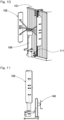
Patent Document 1 is excellent in terms of ease of transport, ease of installation, as well as power generation capacity. In order to further enhance ease of installation of such a wind power generation apparatus, a non-published proposed example as shown inFig. 10 is provided, in which a linear-motion guidingdevice 111 is disposed on the wall of thecontainer 101, and the lower end of thesupport column 106 of thewind turbine 102 is attached to a vertically movable slider of the linear-motion guidingdevice 111. In this proposed example, to attach thewind turbine 102 to the linear-motion guidingdevice 111, thewind turbine 102 is brought to the attachment position by using amanual lift 140 or the like as shown inFig. 11 . - As shown in the exploded perspective view of
Fig. 12 , in order to attach the lower end of thesupport column 106 of thewind turbine 102 to theslider 112 of the linear-motion guidingdevice 111, thesupport column 106 is provided with a support-columnlower end member 110 at the lower end thereof, and bolts (not illustrated) are inserted through thebolt insertion holes 118 in the support-columnlower end member 110 and then are fastened to the threadedholes 117 in theslider 112 to fix the lower end of the support column to the slider. - However, when the wind turbine is to be fixed to the
slider 112 of the linear-motion guidingdevice 111 with bolts, in some cases, it may take time to attach the wind turbine if thewind turbine 102 is inclined due to unevenness of the ground or the like, and thus thebolt insertion holes 118 do not come into alignment with the threadedholes 117. In addition, when thewind turbine 102 is to be fixed to thecontainer 101 with bolts in order to enhance fixation after thewind turbine 102 is fixed to the linear-motion guidingdevice 111 with bolts and is brought up by using themanual lift 140 or the like, in some cases, it may take time to attach the wind turbine if the holes inwind turbine 102 do not come into alignment with the holes in thecontainer 101. - An object of the present invention is to provide a containerized mobile wind power generation apparatus that is excellent in terms of ease of transport and ease of installation, in particular, is further enhanced in terms of ease of installation in that it is possible to eliminate the time required for attachment due to misalignment with the threaded hole when the lower end of the support column of the wind turbine is to be fixed to the slider of the linear-motion guiding device with a bolt.
- The present invention provides a containerized mobile wind power generation apparatus including:
- a container;
- a wind turbine capable of being housed in the container; and
- a generator configured to be driven by the wind turbine to generate power,
- wherein the containerized mobile wind power generation apparatus further includes a linear-motion guiding device on a wall of the container, the linear-motion guiding device including a slider which is vertically movable.
- The wind turbine includes a rotary blade assembly which is disposed at an upper end of a support column, and a support-column lower end member which is disposed at a lower end of the support column and can be fixed to the slider, and the wind turbine can be moved vertically along with the slider when the support-column lower end member is fixed to the slider.
- The slider is provided with a guide member, and the wind turbine can be fixed to the slider by inserting a bolt through a bolt insertion hole in the support-column lower end member and screwing the bolt into a threaded hole in the guide member.
- The containerized mobile wind power generation apparatus includes an attachment guide part configured to guide the support-column lower end member to a position and an attitude in which the bolt insertion hole in the support-column lower end member is aligned with the threaded hole in the guide member when the support-column lower end member is not fixed to the slider.
- According to this configuration, the wind turbine of the wind power generator housed in the container can be set up more easily, so that power demand can be immediately met even in areas affected by disasters or the like. This containerized mobile wind power generation apparatus includes a linear-motion guiding device disposed on a wall of the container, the linear-motion guiding device including a slider which is vertically movable. And the wind turbine includes, at a lower end of the support column, a support-column lower end member which can be fixed to the slider, the wind turbine can be moved vertically along with the slider when the support-column lower end member is fixed to the slider, and the wind turbine can be fixed to the slider by inserting a bolt through a bolt insertion hole in the support-column lower end member and screwing the bolt into a threaded hole in the guide member. Thus, installation operation is facilitated.
- In particular, since the containerized mobile wind power generation apparatus includes the attachment guide part configured to guide the support-column lower end member to a position and an attitude in which the bolt insertion hole in the support-column lower end member is aligned with the threaded hole in the guide member when the support-column lower end member is not fixed to the slider, the support-column lower end member of the wind turbine is guided by the attachment guide part such that the bolt insertion hole in the support-column lower end member is aligned with the threaded hole in the slider, when the wind turbine is to be fixed by a bolt to the threaded hole in the linear-motion guiding device. Thus, installation can be further facilitated in that it is possible to eliminate the time required for attachment due to misalignment with the threaded hole. Also in the case where the wind turbine guided by the linear-motion guiding device to the upper part of the container is to be fastened to the container with a bolt so as to be maintained at this position, the wind turbine assumes an upright attitude at the attachment guide part, so that alignment with the threaded hole can be easily attained even at this position, making it very easy to fix the wind turbine with a bolt.
- In the present invention, the attachment guide part may include: a stepped bolt including a shaft part and a head part having a larger diameter than that of the shaft part; a hook slot provided in the support-column lower end member, the hook slot having, in a lower part thereof, a large diameter part through which the head part of the stepped bolt can pass and, in an upper part thereof, a narrow part having a width that permits the shaft part of the stepped bolt to pass through but does not permit the head part to pass through; and a flanged step part including a receiving part configured to receive a lower face of the support-column lower end member and a flange part extending upward from an end of the receiving part opposite from the container so as to engage with a side face of the support-column lower end member opposite from the container.
- As long as the attachment guide part can guide the support-column lower end member to a position and an attitude in which the bolt insertion hole in the support-column lower end member is aligned with the threaded hole in the guide member when the support-column lower end member is not fixed to the slider, the attachment guide part may have various forms. However, the attachment guide part including a stepped bolt, a hook slot, and a flanged step part as described above has a simple configuration and is excellent in operability. Stated another way, in order to make the column part of the wind turbine upright with respect to the container regardless of unevenness of the ground, the wind turbine could be positioned using a guide pin in an example. In such a case, however, it is difficult to bring the heavy wind turbine that is not upright into alignment and engagement aligning with a guide pin, and it is also difficult to hold the wind turbine in the engaged state. In contrast, in the case where the attachment guide part includes the stepped bolt and the hook slot as well as the flanged step part, the structure including the stepped bolt and the flanged step part configured to receive the wind turbine requires only that the wind turbine be brought into engagement with the stepped bolt, so that the wind turbine can be hooked on the stepped bolt under its own weight and be stably held temporarily. Therefore, the operation can be performed safely. As used herein, the "stepped bolt" may have a form including a head part, a male thread and a non-threaded shaft part between the head part and the male thread or, simply, a form including a shaft part that is threaded entirely and a head part having a larger diameter than that of the shaft part.
- In the present invention, the wind turbine may be a vertical wind turbine including a central rotary member disposed so as to be rotatable about a vertical axis and a plurality of blades extending vertically around the central rotary member. In the case where the wind turbine is a vertical wind turbine, the wind turbine can rotate without being affected by the wind direction, can rotate even in light wind, and is also excellent in noise reduction performance.
- In the present invention, the containerized mobile wind power generation apparatus may include upper and lower to-be-engaged parts in an upper part of the container and a lower part of the support column of the wind turbine, respectively, and a winder including upper and lower hook parts configured to be engaged with the upper and lower to-be-engaged parts, respectively, and change a distance between the upper and lower hook parts. In the case where the containerized mobile wind power generation apparatus includes a winder in combination with a linear-motion guiding device, the operations to lift and lower the wind turbine can be facilitated when the wind turbine is lifted to the upper part of the container to be set up on the container and when the wind turbine is lowered from the upper part of container to be housed therein. The configuration in which the to-be-engaged parts are provided at the upper part of the container and the lower part of the support column of the wind turbine, and the upper and lower to-be-engaged parts are configured to be engaged with the upper and lower hook parts of the winder, respectively, can eliminate the necessity of fixing the winder to the container or the like, so that the winder can be easily arranged.
- The winder may be an electric winder. Either a manual or electric winder may be used. However, winding operation using a manual winder may not be so easy in the case where the winder is designed to be used with the upper and lower hook parts engaged. Therefore, it is preferable to use an electric winder.
- The present invention encompasses any combination of at least two features disclosed in the claims and/or the specification and/or the drawings. In particular, any combination of two or more of the appended claims should be equally construed as included within the scope of the present invention.
- The present invention will be more clearly understood from the following description of preferred embodiments thereof, when taken in conjunction with the accompanying drawings. However, the embodiments and the drawings are given only for the purpose of illustration and explanation, and are not to be taken as limiting the scope of the present invention in any way whatsoever, which scope is to be determined by the appended claims. In the accompanying drawings, like reference numerals are used to denote like or corresponding parts throughout the several views.
-
Fig. 1 is a perspective view showing a use state of a containerized mobile wind power generation apparatus according to one embodiment of the present invention; -
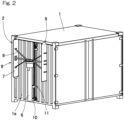
Fig. 2 is a perspective view showing a state of the containerized mobile wind power generation apparatus with the wind turbine lowered; -
Fig. 3 is a front view showing a use state of the containerized mobile wind power generation apparatus; -
Fig. 4 is an enlarged front view showing a winder of the containerized mobile wind power generation apparatus and the surrounding part thereof; -
Fig. 5 is an enlarged perspective view showing a state of the container front part of the containerized mobile wind power generation apparatus with the wind turbine lowered; -
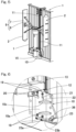
Fig. 6 is an enlarged perspective view showing part VI ofFig. 5 ; -
Fig. 7 is an exploded perspective view showing the same part of the containerized mobile wind power generation apparatus as the part shown inFig. 5 ; -
Fig. 8 is an exploded perspective view showing the same part of the containerized mobile wind power generation apparatus as the part shown inFig. 6 ; -
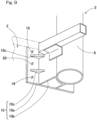
Fig. 9 is a bird's eye perspective view showing a support-column lower end member of the containerized mobile wind power generation apparatus and the surrounding part thereof; -
Fig. 10 is a front view showing a state of the container front part of a containerized mobile wind power generation apparatus according to a proposed example, with the wind turbine lowered; -
Fig. 11 is a side view of a manual lift of the containerized mobile wind power generation apparatus according to the proposed example; and -
Fig. 12 is a perspective view showing a fixing structure for the lower part of the wind turbine support column of the containerized mobile wind power generation apparatus according to the proposed example. - A containerized mobile wind power generation apparatus according to one embodiment of the present invention is described with reference to
Fig. 1 to Fig. 9 . InFig. 1 , the containerized mobile wind power generation apparatus includes acontainer 1, awind turbine 2 which can be housed in thecontainer 1, and agenerator 3 which is driven by thewind turbine 2 to generate power. - The
container 1 has narrower dimensions than the standard dimensions, so that thecontainer 1 can be carried by, for example, a general 4-ton truck. Thecontainer 1, however, may be a container having the standard dimensions for freight transport. - The
wind turbine 2 is a vertical-axis wind turbine including acentral rotary member 5 disposed in an upper part of asupport column 6 in a rotatable manner about the vertical axis, a plurality ofblades 7 extending vertically around thecentral rotary member 5 with coupling theblades 7 to thecentral rotary member 5 viaarms 8. The plurality ofblades 7 and thearms 8 constitute arotary blade assembly 9. Thecentral rotary member 5 may be the main shaft or the like. Thesupport column 6 is formed from a round steel pipe or the like, and thecentral rotary member 5 of thewind turbine 2 is disposed at the upper end of the support column in a rotatable manner through a bearing (not illustrated). Thegenerator 3 and the bearing are disposed inside thecentral rotary member 5 and are coupled thereto in such a way that rotation of thecentral rotary member 5 can be transferred to the rotor of thegenerator 3. - A linear-
motion guiding device 11 is disposed on thewall 1a of one end of thecontainer 1 along the vertical direction, and thewind turbine 2 is attached to a slider 12 (seeFig. 8 ) of the linear-motion guiding device 11 by a support-columnlower end member 10 disposed at the lower end of thesupport column 6. The linear-motion guiding device 11 includes arail 13 and theslider 12 that can slide vertically along therail 13, as shown inFig. 8 in a partly enlarged manner. The linear-motion guiding device 11 includes a linear rolling bearing in this embodiment and has, inside theslider 12, circulation paths (none illustrated) for moving a plurality of rolling elements (none illustrated) which roll on and contact with therail 13, so that the rolling elements can circulate. There are a plurality of circulation paths, so that the rolling elements roll in the raceway grooves on the opposite side surfaces of therail 13. - Vertical movement of the
wind turbine 2 along the linear-motion guiding device 11 is enabled by awinder 31 shown inFig. 4 . Thewinder 31 is an electric winder in this embodiment. Thewinder 31 includes awinder case 32, a rotary drum disposed therein, wire members such as wire ropes extending vertically and wound around the rotary drum (none illustrated), and hooks 33, 34 provided to the ends of the upper and lower wire members, respectively. The rotary drum can be rotated backward and forward by a motor (not illustrated) disposed in thewinder case 32 to wind or unwind, i.e., shorten or extend the distance between the upper andlower hooks lower hooks winder case 32. The upper andlower hooks winder 31 are hooked on upper and lower to-be-engaged parts container 1 and to the support-columnlower end member 10 of thewind turbine 2, respectively. The upper and lower to-be-engaged parts - As shown in
Fig. 5 to Fig. 8 , thewind turbine 2 is attached to theslider 12 of the linear-motion guiding device 11 in the following manner. - As shown in the exploded perspective view of
Fig. 8 , aguide member 15 is disposed on the front face of theslider 12. Theguide member 15 includes, in this example, twoparallel guide plates 15a in the form of thin plates extending in the direction of linear motion of the linear-motion guiding device 11. Theguide member 15 is attached to theslider 12 byfasteners 16 such as bolts. Theguide member 15 has threadedholes 17 at a plurality of positions. The threaded holes 17 may be formed by directly threading theguide member 15 or by welding nuts or the like. The support-columnlower end member 10 has bolt insertion holes 18 corresponding to the threadedholes 17, and respective bolts 19 (Fig. 6 ,Fig. 9 ) inserted through the bolt insertion holes 18 are screwed into and fastened to the threadedholes 17 to fix the support-columnlower end member 10 of thewind turbine 2 to theslider 12. - The support-column
lower end member 10 includes, for example, as shown in e.g.Fig. 9 , abase plate part 10a, a support-column joiningplate part 10b protruding from thebase plate part 10a toward thesupport column 6, and reinforcingplate parts 10c which are respective two parts joined adjacent to thebase plate part 10a and the support-column joiningplate part 10b. The support-column joiningplate part 10b shown inFig. 9 is omitted inFig. 6 andFig. 8 . For the sake of expedience, the drawings inFig. 6 andFig. 8 have different dimensional relations from that of the drawing inFig. 9 . The support-columnlower end member 10 includes, at the lower part thereof, a protrudingpart 10d to which the lower to-be-engaged part 36 is attached. Illustration of theprotruding part 10d is omitted inFig. 9 . - In order to facilitate the operation of screwing the
bolts 19, anattachment guide part 20 is provided. The attachment guidepart 20 is a part for guiding the support-columnlower end member 10 to a position and an attitude in which the bolt insertion holes 18 of the support-columnlower end member 10 are aligned with the threadedholes 17 of theguide member 20 when the support-columnlower end member 10 is not fixed to theslider 12. - The attachment guide
part 20 includes a plurality of steppedbolts 21, a plurality ofhook slots 22, and oneflanged step part 23. Each steppedbolt 21 includes ashaft part 21a and ahead part 21b having a larger diameter than that of theshaft part 21a. Thehook slots 22 are formed in the support-columnlower end member 10. Each hook slot has, in the lower part thereof, a large diameter part 22b through which thehead part 21b of a steppedbolt 21 can pass and, in the upper part thereof, a narrow part having a width that permits theshaft part 21a of the steppedbolt 21 to pass through but does not permit thehead part 21b to pass through. Eachhook slot 22 has a so-called keyhole like shape. Theflanged step part 23 includes a receivingpart 23a for receiving the lower face of the support-columnlower end member 10 and aflange part 23b extending upward from the end of the receivingpart 23a opposite from the container so as to engage with the side face of the support-columnlower end member 10 opposite from the container. - According to the configuration of this embodiment, the
wind turbine 2 received in thecontainer 1 can be more easily set up, so that power demand can be immediately met even in areas affected by disasters or the like. This containerized mobile wind power generation apparatus includes a linear-motion guiding device 11 disposed on the wall of thecontainer 1, the linear-motion guiding device including theslider 12 which can be moved vertically. And thewind turbine 2 can be moved vertically along with theslider 12 with the support-columnlower end member 10 at the lower end of thesupport column 6 fixed to theslider 12, and thewind turbine 2 can be fixed to theslider 12 by inserting the bolts 19 (Fig. 6 ) through the bolt insertion holes 18 (Fig. 8 ) in the support-columnlower end member 10 and screwing the bolts into threaded holes 17 (Fig. 8 ) in theguide member 15. Thus, installation operation is facilitated. - In particular, the linear-
motion guiding device 11 is provided with theattachment guide part 20 in order to facilitate attachment of thewind turbine 2 to the linear-motion guiding device 11. The attachment guidepart 20 includes the steppedbolts 21 and theflanged step part 23 for receiving thewind turbine 2. The attachment guide part also includes, on the side facing toward thewind turbine 2, the keyhole-like-shapedhook slots 22 for hooking on the steppedbolts 21. Thus, on attaching thewind turbine 2 to the linear-motion guiding device 11, thewind turbine 2 can be hooked on the steppedbolts 21 and temporarily placed on theflanged step part 23 of theattachment guide part 20, so that thewind turbine 2 can be brought upright and the threadedholes 17 are aligned. In this way, the wind turbine can be fixed with bolts very easily. - Furthermore, even on lifting the
wind turbine 2 using the winder 31 (Fig. 4 ) to the upper end as shown inFig. 9 and fixing it to thecontainer 1 with bolts, thewind turbine 2 is set upright by theattachment guide part 20, so that the threaded holes are aligned. In this way, the wind turbine can be fixed with bolts very easily. - Although the present invention has been described in terms of the preferred embodiments thereof with reference to the drawings, various additions, modifications, or deletions may be made without departing from the scope of the invention. Accordingly, such variants are included within the scope of the present invention.
-
- 1
- container
- 2
- wind turbine
- 3
- generator
- 6
- support column
- 9
- rotary blade assembly
- 10
- support-column lower end member
- 11
- linear-motion guiding device
- 12
- slider
- 13
- rail
- 15
- guide member
- 15a, 15a
- guide plate
- 17
- threaded hole
- 18
- bolt insertion hole
- 19
- bolt
- 20
- attachment guide part
- 21
- stepped bolt
- 21a
- shaft part
- 21b
- head part
- 22
- hook slot
- 23
- flanged step part
- 23a
- receiving part
- 23b
- flange part
- 31
- winder
- 33, 34
- hook
- 35, 36
- to-be-engaged part
Claims (5)
- A containerized mobile wind power generation apparatus comprising:a container;a wind turbine capable of being housed in the container; anda generator configured to be driven by the wind turbine to generate power,the containerized mobile wind power generation apparatus further comprising a linear-motion guiding device disposed on a wall of the container, the linear-motion guiding device including a slider capable of being moved vertically,wherein the wind turbine includes a rotary blade assembly disposed at an upper end of a support column, and a support-column lower end member disposed at a lower end of the support column and capable of being fixed to the slider, and the wind turbine can be moved vertically along with the slider when the support-column lower end member is fixed to the slider,the slider is provided with a guide member, and the wind turbine can be fixed to the slider by inserting a bolt through a bolt insertion hole in the support-column lower end member and screwing the bolt into a threaded hole in the guide member, andthe containerized mobile wind power generation apparatus includes an attachment guide part configured to guide the support-column lower end member to a position and an attitude in which the bolt insertion hole in the support-column lower end member is aligned with the threaded hole in the guide member when the support-column lower end member is not fixed to the slider.
- The containerized mobile wind power generation apparatus as claimed in claim 1, wherein the attachment guide part includes: a stepped bolt including a shaft part and a head part having a larger diameter than that of the shaft part; a hook slot provided in the support-column lower end member, the hook slot having, in a lower part thereof, a large diameter part through which the head part of the stepped bolt can pass and, in an upper part thereof, a narrow part having a width that permits the shaft part of the stepped bolt to pass through but does not permit the head part to pass through; and a flanged step part including a receiving part configured to receive a lower face of the support-column lower end member and a flange part extending upward from an end of the receiving part opposite from the container so as to engage with a side face of the support-column lower end member opposite from the container.
- The containerized mobile wind power generation apparatus as claimed in claim 1 or 2, wherein the wind turbine is a vertical wind turbine including a central rotary member disposed so as to be rotatable about a vertical axis and a plurality of blades extending vertically around the central rotary member.
- The containerized mobile wind power generation apparatus as claimed in any one of claims 1 to 3, comprisingupper and lower to-be-engaged parts in an upper part of the container and a lower part of the support column of the wind turbine, respectively, anda winder including upper and lower hook parts configured to be engaged with the upper and lower to-be-engaged parts, respectively, and change a distance between the upper and lower hook parts.
- The containerized mobile wind power generation apparatus as claimed in claim 4, wherein the winder is an electric winder.
Applications Claiming Priority (2)
| Application Number | Priority Date | Filing Date | Title |
|---|---|---|---|
| JP2020162167A JP7432476B2 (en) | 2020-09-28 | 2020-09-28 | Mobile wind power generator stored in a container |
| PCT/JP2021/034621 WO2022065314A1 (en) | 2020-09-28 | 2021-09-21 | Containerized mobile wind power generation apparatus |
Publications (3)
| Publication Number | Publication Date |
|---|---|
| EP4219936A1 true EP4219936A1 (en) | 2023-08-02 |
| EP4219936A4 EP4219936A4 (en) | 2024-10-02 |
| EP4219936B1 EP4219936B1 (en) | 2026-01-28 |
Family
ID=80845516
Family Applications (1)
| Application Number | Title | Priority Date | Filing Date |
|---|---|---|---|
| EP21872443.3A Active EP4219936B1 (en) | 2020-09-28 | 2021-09-21 | Containerized mobile wind power generation apparatus |
Country Status (5)
| Country | Link |
|---|---|
| US (1) | US12180927B2 (en) |
| EP (1) | EP4219936B1 (en) |
| JP (1) | JP7432476B2 (en) |
| CN (1) | CN116249830A (en) |
| WO (1) | WO2022065314A1 (en) |
Families Citing this family (4)
| Publication number | Priority date | Publication date | Assignee | Title |
|---|---|---|---|---|
| JPWO2023189844A1 (en) | 2022-03-30 | 2023-10-05 | ||
| JP2024121592A (en) * | 2023-02-27 | 2024-09-06 | Ntn株式会社 | Power Supplies |
| US12385471B2 (en) * | 2023-06-12 | 2025-08-12 | BDE Inventions, LLC | Portable and retractable off-grid turbine system |
| CN116928030A (en) * | 2023-06-28 | 2023-10-24 | 四川华能康定水电有限责任公司 | Power supply device of hydropower station collector |
Family Cites Families (15)
| Publication number | Priority date | Publication date | Assignee | Title |
|---|---|---|---|---|
| DE3405466A1 (en) * | 1984-02-16 | 1985-08-22 | Josef 7918 Illertissen Holzner | Mobile solar station which can be combined with a wind-energy generator |
| JP3014093B1 (en) | 1998-09-22 | 2000-02-28 | 株式会社スイデン | Wind power generator |
| CH695707A5 (en) * | 2003-04-07 | 2006-07-31 | Robert Niederer | Supply unit for electricity and water on the basis of renewable energies. |
| CN201228615Y (en) * | 2008-07-24 | 2009-04-29 | 崨豹科技有限公司 | Mobile wind power generation plant |
| US20100032955A1 (en) * | 2008-08-06 | 2010-02-11 | Chen Shih H | Mobile wind power generating device |
| US20110027100A1 (en) * | 2009-07-30 | 2011-02-03 | Daniel Francis Cummane | Mobile wind power station |
| US10711476B2 (en) | 2012-02-17 | 2020-07-14 | Future Proof, LLC | Modular utilities unit structure |
| US20190326846A1 (en) | 2016-10-14 | 2019-10-24 | HCI Eneergy, LLC | Hybrid utility system and method |
| WO2017066669A1 (en) | 2015-10-14 | 2017-04-20 | Ansari Reza | Transportable hybrid power system |
| US9780720B2 (en) | 2012-02-17 | 2017-10-03 | Hci Energy, Llc | Transportable hybrid power system |
| US9221136B2 (en) | 2012-02-17 | 2015-12-29 | Reza Ansari | Transportable hybrid power system |
| CN203571563U (en) * | 2013-11-29 | 2014-04-30 | 四川新力光源股份有限公司 | Ceiling lamp with directional mounting structure |
| JP7191627B2 (en) | 2018-10-09 | 2022-12-19 | Ntn株式会社 | vertical axis wind turbine |
| WO2020075617A1 (en) * | 2018-10-09 | 2020-04-16 | Ntn株式会社 | Vertical shaft wind power generation device and hydropower generation device accommodated in container |
| CN112840122A (en) | 2018-10-09 | 2021-05-25 | Ntn株式会社 | Vertical axis wind power generation device and container storage hydroelectric power generation device |
-
2020
- 2020-09-28 JP JP2020162167A patent/JP7432476B2/en active Active
-
2021
- 2021-09-21 WO PCT/JP2021/034621 patent/WO2022065314A1/en not_active Ceased
- 2021-09-21 CN CN202180062833.9A patent/CN116249830A/en active Pending
- 2021-09-21 EP EP21872443.3A patent/EP4219936B1/en active Active
-
2023
- 2023-03-14 US US18/121,341 patent/US12180927B2/en active Active
Also Published As
| Publication number | Publication date |
|---|---|
| US12180927B2 (en) | 2024-12-31 |
| CN116249830A (en) | 2023-06-09 |
| WO2022065314A1 (en) | 2022-03-31 |
| JP7432476B2 (en) | 2024-02-16 |
| EP4219936B1 (en) | 2026-01-28 |
| EP4219936A4 (en) | 2024-10-02 |
| US20230213019A1 (en) | 2023-07-06 |
| JP2022054905A (en) | 2022-04-07 |
Similar Documents
| Publication | Publication Date | Title |
|---|---|---|
| EP4219936B1 (en) | Containerized mobile wind power generation apparatus | |
| CN103210211B (en) | Wind turbine blade is arranged on the Apparatus and method on wind turbine tower | |
| US9476403B2 (en) | Wind turbine blade lowering apparatus | |
| US8083212B2 (en) | Wind-turbine rotor-blade hoisting apparatus, method for attaching wind-turbine rotor blade, and method for constructing wind power generator | |
| US11255312B2 (en) | Flange frame and assembly set for pre-assembling and/or transporting and/or assembling a tower segment for a wind turbine, and methods | |
| CN107923361B (en) | Method of moving wind turbine components and transport system for moving wind turbine components | |
| US20190181730A1 (en) | Method for removing or installing a stator segment of a generator being installed in a nacelle of a wind turbine | |
| US7475867B1 (en) | Fairleads for building platforms | |
| US12404148B2 (en) | Adaptor for providing an adjustable connection between an endpiece of a lifting apparatus and a nacelle, and method of using same | |
| EP4392671B1 (en) | Handling a power cable of a wind turbine | |
| US12276264B2 (en) | Cable guiding structure for a tower for a wind turbine, method for mounting a cable guiding structure, and wind turbine | |
| US12270384B2 (en) | Connection system for attaching a blade access system to a nacelle of a wind turbine and method of using same | |
| US11754049B2 (en) | Platform for a wind turbine, wind turbine with the platform and method for assembling a wind turbine | |
| US11098697B2 (en) | Equipment for handling a wind turbine component and method of assembling such equipment and handling a wind turbine component using such equipment | |
| BE1028770B1 (en) | Swimming pool cover mechanism | |
| CN223688006U (en) | Tower climbing assistance devices and tower climbing wearable equipment | |
| US20250122744A1 (en) | Stabilized wind turbines, systems for stabilizing wind turbines, and methods for installing same | |
| US20260062260A1 (en) | A lifting system for lifting components to an elongated structure | |
| CN114214941A (en) | Reverse lifting equipment for mounting separated suspension bridge steel beam and construction method thereof |
Legal Events
| Date | Code | Title | Description |
|---|---|---|---|
| STAA | Information on the status of an ep patent application or granted ep patent |
Free format text: STATUS: THE INTERNATIONAL PUBLICATION HAS BEEN MADE |
|
| PUAI | Public reference made under article 153(3) epc to a published international application that has entered the european phase |
Free format text: ORIGINAL CODE: 0009012 |
|
| STAA | Information on the status of an ep patent application or granted ep patent |
Free format text: STATUS: REQUEST FOR EXAMINATION WAS MADE |
|
| 17P | Request for examination filed |
Effective date: 20230315 |
|
| AK | Designated contracting states |
Kind code of ref document: A1 Designated state(s): AL AT BE BG CH CY CZ DE DK EE ES FI FR GB GR HR HU IE IS IT LI LT LU LV MC MK MT NL NO PL PT RO RS SE SI SK SM TR |
|
| DAV | Request for validation of the european patent (deleted) | ||
| DAX | Request for extension of the european patent (deleted) | ||
| A4 | Supplementary search report drawn up and despatched |
Effective date: 20240903 |
|
| RIC1 | Information provided on ipc code assigned before grant |
Ipc: F03D 13/40 20160101ALI20240828BHEP Ipc: F03D 3/06 20060101ALI20240828BHEP Ipc: F03D 13/20 20160101AFI20240828BHEP |
|
| STAA | Information on the status of an ep patent application or granted ep patent |
Free format text: STATUS: EXAMINATION IS IN PROGRESS |
|
| 17Q | First examination report despatched |
Effective date: 20250327 |
|
| GRAP | Despatch of communication of intention to grant a patent |
Free format text: ORIGINAL CODE: EPIDOSNIGR1 |
|
| STAA | Information on the status of an ep patent application or granted ep patent |
Free format text: STATUS: GRANT OF PATENT IS INTENDED |
|
| INTG | Intention to grant announced |
Effective date: 20250910 |
|
| GRAS | Grant fee paid |
Free format text: ORIGINAL CODE: EPIDOSNIGR3 |
|
| GRAA | (expected) grant |
Free format text: ORIGINAL CODE: 0009210 |
|
| STAA | Information on the status of an ep patent application or granted ep patent |
Free format text: STATUS: THE PATENT HAS BEEN GRANTED |
|
| AK | Designated contracting states |
Kind code of ref document: B1 Designated state(s): AL AT BE BG CH CY CZ DE DK EE ES FI FR GB GR HR HU IE IS IT LI LT LU LV MC MK MT NL NO PL PT RO RS SE SI SK SM TR |
|
| REG | Reference to a national code |
Ref country code: CH Ref legal event code: F10 Free format text: ST27 STATUS EVENT CODE: U-0-0-F10-F00 (AS PROVIDED BY THE NATIONAL OFFICE) Effective date: 20260128 Ref country code: GB Ref legal event code: FG4D |
|
| REG | Reference to a national code |
Ref country code: DE Ref legal event code: R096 Ref document number: 602021047267 Country of ref document: DE |
|
| REG | Reference to a national code |
Ref country code: IE Ref legal event code: FG4D |
|
| REG | Reference to a national code |
Ref country code: NL Ref legal event code: MP Effective date: 20260128 |
|
| PG25 | Lapsed in a contracting state [announced via postgrant information from national office to epo] |
Ref country code: NL Free format text: LAPSE BECAUSE OF FAILURE TO SUBMIT A TRANSLATION OF THE DESCRIPTION OR TO PAY THE FEE WITHIN THE PRESCRIBED TIME-LIMIT Effective date: 20260128 |
|
| REG | Reference to a national code |
Ref country code: AT Ref legal event code: MK05 Ref document number: 1881542 Country of ref document: AT Kind code of ref document: T Effective date: 20260128 |
|
| PG25 | Lapsed in a contracting state [announced via postgrant information from national office to epo] |
Ref country code: RS Free format text: LAPSE BECAUSE OF FAILURE TO SUBMIT A TRANSLATION OF THE DESCRIPTION OR TO PAY THE FEE WITHIN THE PRESCRIBED TIME-LIMIT Effective date: 20260428 |
|
| PG25 | Lapsed in a contracting state [announced via postgrant information from national office to epo] |
Ref country code: ES Free format text: LAPSE BECAUSE OF FAILURE TO SUBMIT A TRANSLATION OF THE DESCRIPTION OR TO PAY THE FEE WITHIN THE PRESCRIBED TIME-LIMIT Effective date: 20260128 |
|
| PG25 | Lapsed in a contracting state [announced via postgrant information from national office to epo] |
Ref country code: PL Free format text: LAPSE BECAUSE OF FAILURE TO SUBMIT A TRANSLATION OF THE DESCRIPTION OR TO PAY THE FEE WITHIN THE PRESCRIBED TIME-LIMIT Effective date: 20260128 |
|
| PG25 | Lapsed in a contracting state [announced via postgrant information from national office to epo] |
Ref country code: GR Free format text: LAPSE BECAUSE OF FAILURE TO SUBMIT A TRANSLATION OF THE DESCRIPTION OR TO PAY THE FEE WITHIN THE PRESCRIBED TIME-LIMIT Effective date: 20260429 |
|
| REG | Reference to a national code |
Ref country code: LT Ref legal event code: MG9D |
|
| PG25 | Lapsed in a contracting state [announced via postgrant information from national office to epo] |
Ref country code: LT Free format text: LAPSE BECAUSE OF FAILURE TO SUBMIT A TRANSLATION OF THE DESCRIPTION OR TO PAY THE FEE WITHIN THE PRESCRIBED TIME-LIMIT Effective date: 20260128 |
|
| PG25 | Lapsed in a contracting state [announced via postgrant information from national office to epo] |
Ref country code: NO Free format text: LAPSE BECAUSE OF FAILURE TO SUBMIT A TRANSLATION OF THE DESCRIPTION OR TO PAY THE FEE WITHIN THE PRESCRIBED TIME-LIMIT Effective date: 20260428 |
|
| PG25 | Lapsed in a contracting state [announced via postgrant information from national office to epo] |
Ref country code: SE Free format text: LAPSE BECAUSE OF FAILURE TO SUBMIT A TRANSLATION OF THE DESCRIPTION OR TO PAY THE FEE WITHIN THE PRESCRIBED TIME-LIMIT Effective date: 20260128 Ref country code: FI Free format text: LAPSE BECAUSE OF FAILURE TO SUBMIT A TRANSLATION OF THE DESCRIPTION OR TO PAY THE FEE WITHIN THE PRESCRIBED TIME-LIMIT Effective date: 20260128 Ref country code: AT Free format text: LAPSE BECAUSE OF FAILURE TO SUBMIT A TRANSLATION OF THE DESCRIPTION OR TO PAY THE FEE WITHIN THE PRESCRIBED TIME-LIMIT Effective date: 20260128 |
|
| PG25 | Lapsed in a contracting state [announced via postgrant information from national office to epo] |
Ref country code: HR Free format text: LAPSE BECAUSE OF FAILURE TO SUBMIT A TRANSLATION OF THE DESCRIPTION OR TO PAY THE FEE WITHIN THE PRESCRIBED TIME-LIMIT Effective date: 20260128 |
|
| PG25 | Lapsed in a contracting state [announced via postgrant information from national office to epo] |
Ref country code: IS Free format text: LAPSE BECAUSE OF FAILURE TO SUBMIT A TRANSLATION OF THE DESCRIPTION OR TO PAY THE FEE WITHIN THE PRESCRIBED TIME-LIMIT Effective date: 20260528 Ref country code: PT Free format text: LAPSE BECAUSE OF FAILURE TO SUBMIT A TRANSLATION OF THE DESCRIPTION OR TO PAY THE FEE WITHIN THE PRESCRIBED TIME-LIMIT Effective date: 20260528 |
|
| PG25 | Lapsed in a contracting state [announced via postgrant information from national office to epo] |
Ref country code: LV Free format text: LAPSE BECAUSE OF FAILURE TO SUBMIT A TRANSLATION OF THE DESCRIPTION OR TO PAY THE FEE WITHIN THE PRESCRIBED TIME-LIMIT Effective date: 20260128 |
|
| PG25 | Lapsed in a contracting state [announced via postgrant information from national office to epo] |
Ref country code: BG Free format text: LAPSE BECAUSE OF FAILURE TO SUBMIT A TRANSLATION OF THE DESCRIPTION OR TO PAY THE FEE WITHIN THE PRESCRIBED TIME-LIMIT Effective date: 20260128 |