EP4219934A1 - Verfahren zur reduzierung einer geräuschemission eines windenergieanlagen-rotorblattes und windenergieanlagen-rotorblatt - Google Patents
Verfahren zur reduzierung einer geräuschemission eines windenergieanlagen-rotorblattes und windenergieanlagen-rotorblatt Download PDFInfo
- Publication number
- EP4219934A1 EP4219934A1 EP22153587.5A EP22153587A EP4219934A1 EP 4219934 A1 EP4219934 A1 EP 4219934A1 EP 22153587 A EP22153587 A EP 22153587A EP 4219934 A1 EP4219934 A1 EP 4219934A1
- Authority
- EP
- European Patent Office
- Prior art keywords
- pressure
- transition
- rotor blade
- trailing edge
- area
- Prior art date
- Legal status (The legal status is an assumption and is not a legal conclusion. Google has not performed a legal analysis and makes no representation as to the accuracy of the status listed.)
- Granted
Links
Images


Classifications
-
- B—PERFORMING OPERATIONS; TRANSPORTING
- B05—SPRAYING OR ATOMISING IN GENERAL; APPLYING FLUENT MATERIALS TO SURFACES, IN GENERAL
- B05C—APPARATUS FOR APPLYING FLUENT MATERIALS TO SURFACES, IN GENERAL
- B05C1/00—Apparatus in which liquid or other fluent material is applied to the surface of the work by contact with a member carrying the liquid or other fluent material, e.g. a porous member loaded with a liquid to be applied as a coating
- B05C1/02—Apparatus in which liquid or other fluent material is applied to the surface of the work by contact with a member carrying the liquid or other fluent material, e.g. a porous member loaded with a liquid to be applied as a coating for applying liquid or other fluent material to separate articles
- B05C1/025—Apparatus in which liquid or other fluent material is applied to the surface of the work by contact with a member carrying the liquid or other fluent material, e.g. a porous member loaded with a liquid to be applied as a coating for applying liquid or other fluent material to separate articles to flat rectangular articles, e.g. flat sheets
-
- F—MECHANICAL ENGINEERING; LIGHTING; HEATING; WEAPONS; BLASTING
- F03—MACHINES OR ENGINES FOR LIQUIDS; WIND, SPRING, OR WEIGHT MOTORS; PRODUCING MECHANICAL POWER OR A REACTIVE PROPULSIVE THRUST, NOT OTHERWISE PROVIDED FOR
- F03D—WIND MOTORS
- F03D1/00—Wind motors with rotation axis substantially parallel to the air flow entering the rotor
- F03D1/06—Rotors
- F03D1/0608—Rotors characterised by their aerodynamic shape
- F03D1/0633—Rotors characterised by their aerodynamic shape of the blades
-
- F—MECHANICAL ENGINEERING; LIGHTING; HEATING; WEAPONS; BLASTING
- F03—MACHINES OR ENGINES FOR LIQUIDS; WIND, SPRING, OR WEIGHT MOTORS; PRODUCING MECHANICAL POWER OR A REACTIVE PROPULSIVE THRUST, NOT OTHERWISE PROVIDED FOR
- F03D—WIND MOTORS
- F03D1/00—Wind motors with rotation axis substantially parallel to the air flow entering the rotor
- F03D1/06—Rotors
- F03D1/065—Rotors characterised by their construction elements
- F03D1/0675—Rotors characterised by their construction elements of the blades
-
- F—MECHANICAL ENGINEERING; LIGHTING; HEATING; WEAPONS; BLASTING
- F03—MACHINES OR ENGINES FOR LIQUIDS; WIND, SPRING, OR WEIGHT MOTORS; PRODUCING MECHANICAL POWER OR A REACTIVE PROPULSIVE THRUST, NOT OTHERWISE PROVIDED FOR
- F03D—WIND MOTORS
- F03D7/00—Controlling wind motors
- F03D7/02—Controlling wind motors the wind motors having rotation axis substantially parallel to the air flow entering the rotor
- F03D7/0296—Controlling wind motors the wind motors having rotation axis substantially parallel to the air flow entering the rotor to prevent, counteract or reduce noise emissions
-
- F—MECHANICAL ENGINEERING; LIGHTING; HEATING; WEAPONS; BLASTING
- F05—INDEXING SCHEMES RELATING TO ENGINES OR PUMPS IN VARIOUS SUBCLASSES OF CLASSES F01-F04
- F05B—INDEXING SCHEME RELATING TO WIND, SPRING, WEIGHT, INERTIA OR LIKE MOTORS, TO MACHINES OR ENGINES FOR LIQUIDS COVERED BY SUBCLASSES F03B, F03D AND F03G
- F05B2230/00—Manufacture
- F05B2230/90—Coating; Surface treatment
-
- F—MECHANICAL ENGINEERING; LIGHTING; HEATING; WEAPONS; BLASTING
- F05—INDEXING SCHEMES RELATING TO ENGINES OR PUMPS IN VARIOUS SUBCLASSES OF CLASSES F01-F04
- F05B—INDEXING SCHEME RELATING TO WIND, SPRING, WEIGHT, INERTIA OR LIKE MOTORS, TO MACHINES OR ENGINES FOR LIQUIDS COVERED BY SUBCLASSES F03B, F03D AND F03G
- F05B2240/00—Components
- F05B2240/20—Rotors
- F05B2240/30—Characteristics of rotor blades, i.e. of any element transforming dynamic fluid energy to or from rotational energy and being attached to a rotor
- F05B2240/304—Details of the trailing edge
-
- F—MECHANICAL ENGINEERING; LIGHTING; HEATING; WEAPONS; BLASTING
- F05—INDEXING SCHEMES RELATING TO ENGINES OR PUMPS IN VARIOUS SUBCLASSES OF CLASSES F01-F04
- F05B—INDEXING SCHEME RELATING TO WIND, SPRING, WEIGHT, INERTIA OR LIKE MOTORS, TO MACHINES OR ENGINES FOR LIQUIDS COVERED BY SUBCLASSES F03B, F03D AND F03G
- F05B2240/00—Components
- F05B2240/20—Rotors
- F05B2240/30—Characteristics of rotor blades, i.e. of any element transforming dynamic fluid energy to or from rotational energy and being attached to a rotor
- F05B2240/304—Details of the trailing edge
- F05B2240/3042—Serrated trailing edge
-
- F—MECHANICAL ENGINEERING; LIGHTING; HEATING; WEAPONS; BLASTING
- F05—INDEXING SCHEMES RELATING TO ENGINES OR PUMPS IN VARIOUS SUBCLASSES OF CLASSES F01-F04
- F05B—INDEXING SCHEME RELATING TO WIND, SPRING, WEIGHT, INERTIA OR LIKE MOTORS, TO MACHINES OR ENGINES FOR LIQUIDS COVERED BY SUBCLASSES F03B, F03D AND F03G
- F05B2240/00—Components
- F05B2240/20—Rotors
- F05B2240/30—Characteristics of rotor blades, i.e. of any element transforming dynamic fluid energy to or from rotational energy and being attached to a rotor
- F05B2240/305—Flaps, slats or spoilers
-
- F—MECHANICAL ENGINEERING; LIGHTING; HEATING; WEAPONS; BLASTING
- F05—INDEXING SCHEMES RELATING TO ENGINES OR PUMPS IN VARIOUS SUBCLASSES OF CLASSES F01-F04
- F05B—INDEXING SCHEME RELATING TO WIND, SPRING, WEIGHT, INERTIA OR LIKE MOTORS, TO MACHINES OR ENGINES FOR LIQUIDS COVERED BY SUBCLASSES F03B, F03D AND F03G
- F05B2260/00—Function
- F05B2260/96—Preventing, counteracting or reducing vibration or noise
-
- Y—GENERAL TAGGING OF NEW TECHNOLOGICAL DEVELOPMENTS; GENERAL TAGGING OF CROSS-SECTIONAL TECHNOLOGIES SPANNING OVER SEVERAL SECTIONS OF THE IPC; TECHNICAL SUBJECTS COVERED BY FORMER USPC CROSS-REFERENCE ART COLLECTIONS [XRACs] AND DIGESTS
- Y02—TECHNOLOGIES OR APPLICATIONS FOR MITIGATION OR ADAPTATION AGAINST CLIMATE CHANGE
- Y02E—REDUCTION OF GREENHOUSE GAS [GHG] EMISSIONS, RELATED TO ENERGY GENERATION, TRANSMISSION OR DISTRIBUTION
- Y02E10/00—Energy generation through renewable energy sources
- Y02E10/70—Wind energy
- Y02E10/72—Wind turbines with rotation axis in wind direction
Definitions
- the present invention relates to a method for reducing noise emissions from a wind turbine rotor blade and wind turbine rotor blade.
- an attachment such.
- a trailing edge comb (serration) can be attached or glued to a trailing edge of a rotor blade.
- the object of the present invention is to further reduce the noise emission of a wind turbine rotor blade during operation.
- This object is achieved by a method for reducing noise emissions from a wind turbine rotor blade according to claim 1 and by a wind turbine rotor blade according to claim 8 .
- the rotor blade has a rotor blade root, a rotor blade tip, a leading edge, a trailing edge, a suction side and a pressure side.
- An add-on part or add-on element can be provided in the area of the pressure side and in particular in the area of the rear edge.
- At the trailing edge z. B. at least one trailing edge comb can be provided with a plurality of teeth.
- first transition between the suction side and the attachment and a second transition between the pressure side and the attachment.
- the transition between the pressure side and the attachment is filled with a leveling compound.
- the attachment can be designed as a trailing edge comb.
- a spatula is applied to a surface of the pressure side and covers the pressure side (second) transition, and particularly a step at the pressure side (second) transition.
- the point on a pressure side of the attachment e.g. the rear edge comb
- the balancing mass can be provided to allow the surface of the pressure side to be lengthened without transition or step.
- a first adhesive tape may be provided at the transition between the suction side and the attachment (e.g. a trailing edge comb). Furthermore, a second adhesive tape may be provided on the surface of the pressure side adjacent to the transition. A third adhesive tape can be provided in the area of the marking. A leveling compound can be applied between the second and third tapes.
- a compensating material for example in the form of an adhesive bead, can be provided in the area of the transition.
- the material can then be distributed using a spatula. All adhesive tapes can then be removed so that a rotor blade is obtained which has a transition between a pressure side and an attachment (e.g. a trailing edge comb), which has been compensated for by a compensation material, so that in the area of the compensation material an extension of a Surface of the pressure side is provided.
- the pressure-side (second) transition can be in the form of an edge, step, depression, recess or recess.
- the (second) transition on the pressure side can be compensated for by applying the leveling compound.
- Such a transition can have a negative effect in a frequency range from 800 Hz. This means that the approved noise level can be exceeded.
- the attachment may be a trailing edge comb, brushes, flat plates, porous flat plates, curved plates, curved serrations or the like.
- a wind turbine rotor blade having a leading edge, a trailing edge, a suction side, a pressure side and an attachment is provided at least partially on the pressure side. There is a pressure-side transition between the pressure side and the add-on part and this is compensated for by applying a leveling compound.
- a recess or a projection is provided in the area of the transition on the pressure side, and the balancing mass is applied in the area of the transition on the pressure side and in the area of the recess or step.
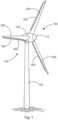
- the wind turbine 100 has a tower 102 and a nacelle 104 on the tower 102 .
- An aerodynamic rotor 106 with three rotor blades 200 and a spinner 110 is provided on the nacelle 104 .
- the aerodynamic rotor 106 is caused to rotate by the wind and thus also rotates a rotor or rotor of a generator, which is directly or indirectly coupled to the aerodynamic rotor 106 .
- the electrical generator is arranged in the nacelle 104 and generates electrical energy.
- the pitch angles of the rotor blades 200 can be changed by pitch motors on the rotor blade roots 210 of the respective rotor blades 200.
- the rotor blade 200 has a rotor blade root 210 , a rotor blade tip 220 , a rotor blade leading edge 230 , a rotor blade trailing edge 240 , a suction side 250 and a pressure side 260 .
- an attachment 300 such. B. a trailing edge comb 300 with a plurality of teeth 320 may be provided.
- the add-on part 300 can also not be provided on the trailing edge 240 but at least partially on the pressure side 260 .
- FIG. 12 shows an illustration of a cross section of a rotor blade according to an aspect of the present invention.
- the rotor blade of 2 can according to a rotor blade 1 are equivalent to.
- An attachment 300 z. B. in the form of a trailing edge comb 300 may be attached to the trailing edge 240 of the rotor blade 200.
- a first (suction-side) transition 241 between the suction side 250 and the attachment 300 (e.g. a trailing edge comb) and a second (pressure-side) transition 242 between a pressure side 260 and the attachment 300 (e.g. a trailing edge comb) can be provided be.
- the second transition 242 can have a recess 263 or a projection 263 . This has the consequence, for example, that the thickness of the trailing edge 240 decreases or increases (suddenly) in the direction of the trailing edge.
- the pressure side 200 has a surface 261 which can be substantially straight in the region of the trailing edge 240 .
- a step backwards or a step 262 can be provided, which is to be compensated for by a balancing mass 400.
- a balancing mass is provided in the area of the second transition between the pressure side and the crest of the trailing edge in order to compensate for the second transition. This leads to a significant reduction in noise emissions, which are caused when the rotor blade is in operation.
- the second transition 242 can optionally have a step back or recess 262 with a step 263 and a length 264 .
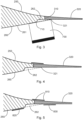
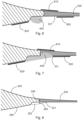
- FIG. 3 to 8 shows a schematic cross-section of a rotor blade of a wind turbine when applying a compensating material on a pressure side of the rotor blade according to an aspect of the present invention.
- the rotor blade 200 has a suction side 250, a pressure side 260, a trailing edge 240 and an attachment z. B. in the form of a trailing edge comb 300 on.
- the pressure side 260 has a surface 261 which can be essentially straight in the region of the trailing edge 240 .
- a first suction-side transition 241 can be provided between the suction side 250 and the trailing edge ridge 300
- a second pressure-side transition 242 can be provided between the pressure side 260 and the trailing edge ridge 300 .
- a setback 262 can be provided in the material of the rotor blade in the area of the trailing edge 240, which is to be compensated for by a balancing mass.
- the second transition 242 may include a recess 262 with a step 263 and a length 264 in the material of the rotor blade.
- a spatula 700 with a first straight end 710 can be provided. The spatula 700 can be placed in the area of the second transition 242 in such a way that the end 210 rests both on a surface 261 of the pressure side and on a pressure side of the trailing edge ridge.
- the point of contact between the end 710 and the pressure side of the trailing edge comb can be provided with a marking 321 . It can thus be determined up to which point the leveling compound 400 should be applied. This is intended to compensate for the transition between the pressure side 260 and the trailing edge ridge 300 .
- a first adhesive tape 810 can be provided in the area of the first transition 241 between the suction side 250 and the trailing edge comb 300 .
- a second adhesive tape 820 may be provided on the pressure side 260 adjacent the second transition 242.
- FIG. A third adhesive tape 830 can be provided in the area of the marking 321 .
- a compensating material 400 can be applied, for example in the form of an adhesive bead.
- the material 400 can then be applied and distributed between the adhesive tapes 820, 830, for example using a spatula 700.
- the surface of the compensating material is then adapted to the surface 261 of the pressure side 260 of the rotor blade in the area of the trailing edge.
- the second transition 242 has been balanced by the balancing mass.
- FIG 9 shows a schematic cross section of a rotor blade according to a further embodiment of the invention.
- the rotor blade according to 9 can in accordance with the rotor blade 2 are equivalent to.
- the rotor blade 200 has a suction side 250 and a pressure side 260 with a surface 261 .
- the rotor blade 200 also has a trailing edge 240 .
- an add-on part 300 can be provided, for example in the form of a trailing edge comb 300 . While according to the embodiment of 2 If there is a recess in the area of the pressure side 260 of the rotor blade, such a recess is not in the rotor blade according to FIG 9 available.
- a first suction-side transition 241 is provided in the area of the suction side 250 and the attachment 300 .
- a second pressure-side transition is provided between the pressure side 260 and the attachment 300 .
- the attachment 300 has a first end 310 with a first, second and third section 311, 312, 313.
- the second and third section 312, 313 extends at least partially along the surface 261 of the pressure side 260.
- This projection 313 has a negative effect on the aerodynamic properties of the rotor blade 200 and in particular on the acoustic properties of the rotor blade.
- a balancing mass 400 is provided in the area of the second pressure-side transition 242 in order to obtain an aerodynamically more favorable transition.
- attachment 300 may represent a trailing edge comb, brushes, flat plates, porous flat plates, curved plates, curved serrations, or the like.
- the decisive factor here is that a recess (as in 3 ) or a protrusion (as in 9 ) is present on the pressure side, so that there is an aerodynamically unfavorable transition.
- the aerodynamically unfavorable transition is processed by means of a balancing mass 400 in order to obtain an aerodynamically more favorable transition.
Landscapes
- Engineering & Computer Science (AREA)
- Life Sciences & Earth Sciences (AREA)
- Sustainable Development (AREA)
- Sustainable Energy (AREA)
- Chemical & Material Sciences (AREA)
- Combustion & Propulsion (AREA)
- Mechanical Engineering (AREA)
- General Engineering & Computer Science (AREA)
- Physics & Mathematics (AREA)
- Fluid Mechanics (AREA)
- Wind Motors (AREA)
- Turbine Rotor Nozzle Sealing (AREA)
Abstract
Description
- Die vorliegende Erfindung betrifft ein Verfahren zur Reduzierung einer Geräuschemission eines Windenergieanlagen-Rotorblattes und Windenergieanlagen-Rotorblatt.
- Zur Reduzierung einer Geräuschemission eines Windenergieanlagen-Rotorblattes beim Betrieb des Rotorblattes kann ein Anbauteil wie z. B. ein Hinterkantenkamm (Serration) an einer Hinterkante eines Rotorblattes angebracht oder angeklebt werden.
- Die Aufgabe der vorliegenden Erfindung besteht darin, die Geräuschemission eines Windenergieanlagen-Rotorblattes beim Betrieb weiter zu reduzieren.
- Diese Aufgabe wird durch ein Verfahren zur Reduktion einer Geräuschemission eines Windenergieanlagen-Rotorblattes nach Anspruch 1 und durch ein Windenergieanlagen-Rotorblatt nach Anspruch 8 gelöst.
- Somit wird ein Verfahren zur Reduzierung einer Geräuschemission eines Windenergieanlagen-Rotorblattes beim Betrieb des Rotorblattes vorgesehen. Das Rotorblatt weist eine Rotorblattwurzel, eine Rotorblattspitze, eine Vorderkante, eine Hinterkante, eine Saugseite und eine Druckseite auf. Im Bereich der Druckseite und insbesondere im Bereich der Hinterkante kann ein Anbauteil oder Anbauelement vorgesehen sein. An der Hinterkante kann z. B. mindestens ein Hinterkantenkamm mit einer Mehrzahl von Zacken vorgesehen sein.
- Ferner ist ein erster Übergang zwischen der Saugseite und dem Anbauteil sowie ein zweiter Übergang zwischen der Druckseite und dem Anbauteil vorhanden. Der Übergang zwischen der Druckseite und dem Anbauteil wird mit einer Ausgleichsmasse aufgefüllt. Das Anbauteil kann als Hinterkantenkamm ausgestaltet sein.
- Gemäß einem Aspekt der vorliegenden Erfindung wird ein Spachtel an eine Oberfläche der Druckseite angelegt und überdeckt den druckseitigen (zweiten) Übergang und insbesondere eine Stufe am druckseitigen (zweiten) Übergang. Der Punkt an einer Druckseite des Anbauteils (z. B. des Hinterkantenkamms), an welchem das freie Ende des Spachtels anliegt, wird markiert und beschreibt denjenigen Bereich, bis zu welchem die Ausgleichsmasse aufzutragen ist. Somit kann die Ausgleichsmasse so vorgesehen werden, dass sie eine Verlängerung der Oberfläche der Druckseite ohne Übergang oder Stufe ermöglicht.
- Gemäß einem Aspekt der vorliegenden Erfindung kann ein erstes Klebeband am Übergang zwischen der Saugseite und dem Anbauteil (z. B. ein Hinterkantenkamm) vorgesehen sein. Ferner kann ein zweites Klebeband auf der Oberfläche der Druckseite benachbart zu dem Übergang vorgesehen sein. Ein dritten Klebeband kann im Bereich der Markierung vorgesehen sein. Eine Ausgleichsmasse kann zwischen dem zweiten und dritten Klebeband aufgetragen werden.
- Gemäß einem weiteren Aspekt kann ein Ausgleichsmaterial beispielsweise in Form einer Klebstoffraupe im Bereich des Übergangs vorgesehen sein. Anschließend kann mittels eines Spachtels das Material verteilt werden. Anschließend können alle Klebebänder entfernt werden, so dass ein Rotorblatt erhalten wird, welches einen Übergang zwischen einer Druckseite und einem Anbauteil (z. B. ein Hinterkantenkamm) aufweist, welcher durch ein Ausgleichsmaterial ausgeglichen worden ist, so dass im Bereich des Ausgleichsmaterials eine Verlängerung einer Oberfläche der Druckseite vorgesehen ist.
- Der druckseitige (zweite) Übergang kann in Form einer Kante, Stufe, Senke, Aussparung oder Ausnehmung vorhanden sein. Durch Aufbringen der Ausgleichsmasse kann der druckseitige (zweite) Übergang ausgeglichen werden. Ein derartiger Übergang kann sich in einem Frequenzbereich ab 800 Hz negativ auswirken. Damit kann der genehmigte Schallpegel überschritten werden.
- Gemäß der Erfindung kann das Anbauteil ein Hinterkantenkamm, Bürsten, flache Platten, poröse flache Platten, gewölbte Platten, gewölbte Serrations oder dergleichen darstellen.
- Gemäß einem Aspekt der vorliegenden Erfindung wird ein Windenergieanlagen-Rotorblatt mit einer Vorderkante, einer Hinterkante, einer Saugseite, einer Druckseite und einem Anbauteil zumindest teilweise an der Druckseite vorgesehen. Ein druckseitiger Übergang zwischen der Druckseite und dem Anbauteil ist vorhanden und wird durch Auftragen einer Ausgleichsmasse ausgeglichen.
- Gemäß einem Aspekt der vorliegenden Erfindung ist im Bereich des druckseitigen Übergangs eine Ausnehmung oder ein Vorsprung vorgesehen und die Ausgleichsmasse wird im Bereich des druckseitigen Übergangs und im Bereich der Ausnehmung bzw. der Stufe aufgetragen.
- Weitere Ausgestaltungen der Erfindung sind Gegenstand der Unteransprüche.
- Vorteile und Ausführungsbeispiele der Erfindung werden nachstehend unter Bezugnahme auf die Zeichnung näher erläutert.
- Fig. 1
- zeigt eine schematische Darstellung einer Windenergieanlage gemäß einem Aspekt der vorliegenden Erfindung,
- Fig. 2
- zeigt eine Darstellung eines Querschnitts eines Rotorblattes gemäß einem Aspekt der vorliegenden Erfindung,
- Fig. 3 bis Fig. 8
- zeigen jeweils einen schematischen Querschnitt eines Rotorblattes einer Windenergieanlage bei Aufbringen eines Ausgleichsmaterials auf einer Druckseite des Rotorblattes gemäß einem Aspekt der vorliegenden Erfindung, und
- Fig. 9
- zeigt einen schematischen Querschnitt eines Rotorblattes gemäß einem weiteren Ausführungsbeispiel.
-
Fig. 1 zeigt eine schematische Darstellung einer Windenergieanlage gemäß einem Aspekt der vorliegenden Erfindung. Die Windenergieanlage 100 weist einen Turm 102 und eine Gondel 104 auf dem Turm 102 auf. An der Gondel 104 ist ein aerodynamischer Rotor 106 mit drei Rotorblättern 200 und einem Spinner 110 vorgesehen. Der aerodynamische Rotor 106 wird im Betrieb der Windenergieanlage durch den Wind in eine Drehbewegung versetzt und dreht somit auch einen Rotor oder Läufer eines Generators, welcher direkt oder indirekt mit dem aerodynamischen Rotor 106 gekoppelt ist. Der elektrische Generator ist in der Gondel 104 angeordnet und erzeugt elektrische Energie. Die Pitchwinkel der Rotorblätter 200 können durch Pitchmotoren an den Rotorblattwurzeln 210 der jeweiligen Rotorblätter 200 verändert werden. - Das Rotorblatt 200 weist eine Rotorblattwurzel 210, eine Rotorblattspitze 220, eine Rotorblattvorderkante 230, eine Rotorblatthinterkante 240, eine Saugseite 250 und eine Druckseite 260 auf. An der Hinterkante 240 kann zumindest teilweise ein Anbauteil 300 wie z. B. ein Hinterkantenkamm 300 mit einer Mehrzahl von Zacken 320 vorgesehen sein.
- Das Anbauteil 300 kann auch nicht an der Hinterkante 240, sondern zumindest teilweise an der Druckseite 260 vorgesehen sein.
-
Fig. 2 zeigt eine Darstellung eines Querschnitts eines Rotorblattes gemäß einem Aspekt der vorliegenden Erfindung. Das Rotorblatt vonFig. 2 kann einem Rotorblatt gemäßFig. 1 entsprechen. Ein Anbauteil 300 z. B. in Form eines Hinterkantenkamms 300 kann an der Hinterkante 240 des Rotorblattes 200 befestigt sein. Hierbei kann ein erster (saugseitiger) Übergang 241 zwischen der Saugseite 250 und dem Anbauteil 300 (z. B. ein Hinterkantenkamm) sowie ein zweiter (druckseitiger) Übergang 242 zwischen einer Druckseite 260 und dem Anbauteil 300 (z. B. ein Hinterkantenkamm) vorgesehen sein. Der zweite Übergang 242 kann einen Rücksprung 263 oder einen Vorsprung 263 aufweisen. Dies hat beispielsweise zur Folge, dass die Dicke der Hinterkante 240 in der Richtung der Hinterkante (sprunghaft) abnimmt oder zunimmt. - Bei der Untersuchung eines erfindungsgemäßen Rotorblattes wurde festgestellt, dass sich der druckseitige (zweite) Übergang an der Druckseite auf unerwartete Art und Weise negativ auf die Geräuschemission des Rotorblattes beim Betrieb auswirkt. Bislang war davon ausgegangen worden, dass lediglich ein derartiger Übergang an der Saugseite sich negativ auf die Geräuschemission auswirkt.
- Gemäß einem Aspekt der Erfindung weist die Druckseite 200 eine Oberfläche 261 auf, welche im Bereich der Hinterkante 240 im Wesentlichen gerade sein kann. Im Bereich des zweiten Übergangs 242 kann ein Rückschritt oder eine Stufe 262 vorgesehen sein, welcher durch eine Ausgleichsmasse 400 auszugleichen ist.
- Erfindungsgemäß wird eine Ausgleichsmasse im Bereich des zweiten Übergangs zwischen Druckseite und Hinterkantenkamm vorgesehen, um den zweiten Übergang auszugleichen. Dies führt zu einer erheblichen Reduzierung der Geräuschemissionen, welche im Betrieb des Rotorblattes hervorgerufen werden.
- Der zweite Übergang 242 kann optional einen Rückschritt bzw. eine Ausnehmung 262 mit einer Stufe 263 und einer Länge 264 aufweisen.
-
Fig. 3 bis Fig. 8 zeigt einen schematischen Querschnitt eines Rotorblattes einer Windenergieanlage bei Aufbringen eines Ausgleichsmaterials auf einer Druckseite des Rotorblattes gemäß einem Aspekt der vorliegenden Erfindung. Das Rotorblatt 200 weist eine Saugseite 250, eine Druckseite 260, eine Hinterkante 240 sowie ein Anbauteil z. B. in Form eines Hinterkantenkamms 300 auf. Die Druckseite 260 weist eine Oberfläche 261 auf, welche im Bereich der Hinterkante 240 im Wesentlichen gerade sein kann. Zwischen der Saugseite 250 und dem Hinterkantenkamm 300 kann ein erster saugseitiger Übergang 241 und zwischen der Druckseite 260 und dem Hinterkantenkamm 300 kann ein zweiter druckseitiger Übergang 242 vorgesehen sein. Im Bereich des zweiten Übergangs 242 kann ein Rückschritt 262 in dem Material des Rotorblattes im Bereich der Hinterkante 240 vorgesehen sein, welcher durch eine Ausgleichsmasse auszugleichen ist. Der zweite Übergang 242 kann einen Rückschritt bzw. eine Ausnehmung 262 mit einer Stufe 263 und einer Länge 264 in dem Material des Rotorblattes aufweisen. Zum Ausgleichen des Rückschritts bzw. im Übergang 262 kann ein Spachtel 700 mit einem ersten geraden Ende 710 vorgesehen sein. Der Spachtel 700 kann dabei derart im Bereich des zweiten Übergangs 242 angelegt werden, dass das Ende 210 sowohl an einer Oberfläche 261 der Druckseite anliegt als auch an einer Druckseite des Hinterkantenkamms anliegt. Wie inFig. 3 zu sehen, ist damit - im Querschnitt - die auszugleichende Fläche durch den Rückschritt 262 und das Ende 710 des Spachtels 700 begrenzt. Optional kann der Berührungspunkt zwischen dem Ende 710 und der Druckseite des Hinterkantenkamms mit einer Markierung 321 versehen werden. Damit kann festgelegt werden, bis zu welchem Punkt die Ausgleichsmasse 400 aufgetragen werden soll. Damit soll der Übergang zwischen der Druckseite 260 und dem Hinterkantenkamm 300 ausgeglichen werden. - Dazu kann beispielsweise wie in
Fig. 4 zu sehen ein erstes Klebeband 810 im Bereich des ersten Übergangs 241 zwischen der Saugseite 250 und dem Hinterkantenkamm 300 vorgesehen sein. - Wie in
Fig. 5 zu sehen, kann ein zweites Klebeband 820 an der Druckseite 260 benachbart zum zweiten Übergang 242 vorgesehen sein. Ein drittes Klebeband 830 kann im Bereich der Markierung 321 vorgesehen sein. - Anschließend kann wie in
Fig. 6 gezeigt ein Ausgleichsmaterial 400 beispielsweise in Form einer Klebstoffraupe aufgetragen werden. Das Material 400 kann dann beispielsweise mittels eines Spachtels 700 zwischen den Klebebändern 820, 830 aufgetragen und verteilt werden. - In
Fig. 8 ist dann das Endergebnis zu sehen. Hierbei ist dann die Oberfläche des Ausgleichsmaterials an die Oberfläche 261 der Druckseite 260 des Rotorblattes im Bereich der Hinterkante angepasst. - Der zweite Übergang 242 ist durch die Ausgleichsmasse ausgeglichen worden.
-
Fig. 9 zeigt einen schematischen Querschnitt eines Rotorblattes gemäß einem weiteren Ausführungsbeispiel der Erfindung. Das Rotorblatt gemäßFig. 9 kann dabei dem Rotorblatt gemäßFig. 2 entsprechen. Das Rotorblatt 200 weist eine Saugseite 250 und eine Druckseite 260 mit einer Oberfläche 261 auf. Das Rotorblatt 200 weist ferner eine Hinterkante 240 auf. Im Bereich der Hinterkante 240 kann ein Anbauteil 300 beispielsweise in Form eines Hinterkantenkamms 300 vorgesehen sein. Während gemäß dem Ausführungsbeispiel vonFig. 2 im Bereich der Druckseite 260 des Rotorblattes eine Ausnehmung vorhanden ist, ist eine derartige Ausnehmung nicht in dem Rotorblatt gemäßFig. 9 vorhanden. Ein erster saugseitiger Übergang 241 ist im Bereich der Saugseite 250 und dem Anbauteil 300 vorgesehen. Ein zweiter druckseitiger Übergang ist zwischen der Druckseite 260 und dem Anbauteil 300 vorgesehen. Gemäß dem Ausführungsbeispiel vonFig. 9 weist das Anbauteil 300 ein erstes Ende 310 mit einem ersten, zweiten und dritten Abschnitt 311, 312, 313 auf. Hierbei erstreckt sich der zweite und dritte Abschnitt 312, 313 zumindest teilweise entlang der Oberfläche 261 der Druckseite 260. Somit ist im Bereich des zweiten druckseitigen Übergangs 242 zwischen der Druckseite 260 und dem Anbauteil 300 eine Stufe oder ein Vorsprung 313 vorhanden. Dieser Vorsprung 313 wirkt sich negativ auf die aerodynamischen Eigenschaften des Rotorblattes 200 und insbesondere auf die akustischen Eigenschaften des Rotorblattes aus. Somit wird analog zu dem Ausführungsbeispiel vonFig. 3 bis Fig. 8 eine Ausgleichsmasse 400 im Bereich des zweiten druckseitigen Übergangs 242 vorgesehen, um einen aerodynamisch günstigeren Übergang zu erhalten. - Gemäß der Erfindung kann das Anbauteil 300 ein Hinterkantenkamm, Bürsten, flache Platten, poröse flache Platten, gewölbte Platten, gewölbte Serrations oder dergleichen darstellen. Maßgeblich ist hierbei, dass eine Ausnehmung (wie in
Fig. 3 ) oder ein Vorsprung (wie inFig. 9 ) an der Druckseite vorhanden ist, so dass ein aerodynamisch ungünstiger Übergang vorhanden ist. - Gemäß einem Aspekt der vorliegenden Erfindung wird mittels einer Ausgleichsmasse 400 der aerodynamisch ungünstige Übergang bearbeitet, um einen aerodynamisch günstigeren Übergang zu erhalten.
-
- 100
- Windenergieanlage
- 102
- Turm
- 104
- Gondel
- 106
- aerodynamischer Rotor
- 110
- Spinner
- 200
- Rotorblätter
- 200b
- Rotorblattwurzeln
- 210
- Rotorblattwurzel
- 220
- Rotorblattspitze
- 230
- Rotorblattvorderkante
- 240
- Rotorblatthinterkante
- 241
- erster Übergang
- 242
- zweiter Übergang
- 250
- Saugseite
- 260
- Druckseite
- 261
- Oberfläche
- 262
- Rückschritt
- 263
- Stufe
- 264
- Ausgleichslänge
- 300
- Anbauteil
- 310
- erstes Ende
- 311
- erster Abschnitt
- 312
- zweiter Abschnitt
- 313
- dritter Abschnitt
- 320
- Zacken
- 321
- Markierung
- 400
- Klebstoff / Ausgleichsmasse
- 700
- Spachtel
- 710
- erstes Ende
- 810
- erstes Klebeband
- 820
- zweites Klebeband
- 830
- drittes Klebeband
Claims (10)
- Verfahren zur Reduzierung einer Geräuschemission eines Windenergieanlagen-Rotorblattes (200), wobei das Windenergieanlagen-Rotorblatt eine Vorderkante (230), eine Hinterkante (240), eine Saugseite (250), eine Druckseite (260) und einen Anbauteil (300) zumindest teilweise an der Druckseite (260) aufweist,wobei ein druckseitiger Übergang (242) zwischen der Druckseite (260) und dem Anbauteil (300) vorhanden ist, mit dem Schritt:Ausgleichen des druckseitigen Übergangs (242) durch Auftragen einer Ausgleichsmasse (400).
- Verfahren nach Anspruch 1, wobeidas Anbauteil (300) als ein Hinterkantenkamm (300) ausgestaltet ist,wobei ein saugseitiger Übergang (241) zwischen der Saugseite (250) und dem Hinterkantenkamm (300) vorhanden ist.
- Verfahren nach Anspruch 1, wobei
im Bereich des druckseitigen Übergangs (242) eine Ausnehmung, insbesondere in Form einer Stufe (262), in einem Material des Rotorblattes (200) an der Druckseite (260) der Hinterkante (240) vorhanden ist. - Verfahren nach Anspruch 2, wobei
zum Ausgleichen des druckseitigen Übergangs (242) ein Spachtel (700) an eine Oberfläche (261) der Druckseite (260) angelegt wird und den druckseitigen Übergang (242) derart überdeckt, dass ein Bereich (321) an einer Druckseite (260) des Hinterkantenkamms (300), an welchem das freie Ende des Spachtels (700) anliegt, einen Ausgleichsmasse-Bereich darstellt, bis zu welchem die Ausgleichsmasse (400) aufzutragen ist. - Verfahren nach Anspruch 3, wobeiein erstes Klebeband (810) am saugseitigen Übergang zwischen der Saugseite und dem Hinterkantenkamm (300) vorgesehen wird,wobei ein zweites Klebeband (820) auf der Oberfläche (261) der Druckseite (260) benachbart zu dem zweiten Übergang (242) vorgesehen wird und wobei ein drittes Klebeband (30) im Ausgleichsmasse-Bereich vorgesehen wird.
- Verfahren nach einem der Ansprüche 1 bis 4, wobei
ein Ausgleichsmaterial (400) im Bereich des druckseitigen Übergangs (242) aufgetragen wird und mittels eines Spachtels (700) verteilt wird. - Verfahren nach Anspruch 1 oder 2, wobeidas Anbauteil (300) zumindest teilweise an der Druckseite (260) angeordnet ist,wobei das Anbauteil (300) ein erstes Ende (310) aufweist,wobei im Bereich des druckseitigen Übergangs (242) ein Vorsprung oder eine Stufe (313) zwischen der Druckseite (260) und dem ersten Ende (310) des Anbauteils (300) vorhanden ist,wobei die Ausgleichsmasse (400) im Bereich des druckseitigen Übergangs (242) aufgetragen ist.
- Windenergieanlagen-Rotorblatt (200), miteiner Vorderkante (230),einer Hinterkante (240),einer Saugseite (250),einer Druckseite (260), undeinem Anbauteil (300) zumindest teilweise an der Druckseite (260),wobei ein druckseitiger Übergang (242) zwischen der Druckseite (260) und dem Anbauteil (300) vorhanden ist,wobei eine Ausgleichsmasse (400) im Bereich des druckseitigen Übergangs (242) vorgesehen ist.
- Windenergieanlagen-Rotorblatt (200) nach Anspruch 8, wobei
im Bereich des druckseitigen Übergangs (242) eine Ausnehmung in einem Material des Rotorblattes (200) an der Druckseite (260) der Hinterkante (240) vorhanden ist, welche durch die Ausgleichsmasse (400) ausgeglichen ist. - Windenergieanlagen-Rotorblatt (200) nach Anspruch 8, wobei
im Bereich des druckseitigen Übergangs (242) ein Vorsprung oder eine Stufe zwischen der Druckseite (260) und einem ersten Ende (310) des Anbauteils (300) vorhanden ist, wobei die Ausgleichsmasse im Bereich des druckseitigen Übergangs aufgetragen ist.
Priority Applications (3)
| Application Number | Priority Date | Filing Date | Title |
|---|---|---|---|
| EP22153587.5A EP4219934B1 (de) | 2022-01-27 | 2022-01-27 | Verfahren zur reduzierung einer geräuschemission eines windenergieanlagen-rotorblattes und windenergieanlagen-rotorblatt |
| CN202310050929.4A CN116498485A (zh) | 2022-01-27 | 2023-01-20 | 风能设备转子叶片和降低其噪音排放的方法 |
| US18/158,846 US20230235722A1 (en) | 2022-01-27 | 2023-01-24 | Method for reducing the noise emission of a wind turbine rotor blade and wind turbine rotor blade |
Applications Claiming Priority (1)
| Application Number | Priority Date | Filing Date | Title |
|---|---|---|---|
| EP22153587.5A EP4219934B1 (de) | 2022-01-27 | 2022-01-27 | Verfahren zur reduzierung einer geräuschemission eines windenergieanlagen-rotorblattes und windenergieanlagen-rotorblatt |
Publications (3)
| Publication Number | Publication Date |
|---|---|
| EP4219934A1 true EP4219934A1 (de) | 2023-08-02 |
| EP4219934B1 EP4219934B1 (de) | 2025-12-24 |
| EP4219934C0 EP4219934C0 (de) | 2025-12-24 |
Family
ID=80121691
Family Applications (1)
| Application Number | Title | Priority Date | Filing Date |
|---|---|---|---|
| EP22153587.5A Active EP4219934B1 (de) | 2022-01-27 | 2022-01-27 | Verfahren zur reduzierung einer geräuschemission eines windenergieanlagen-rotorblattes und windenergieanlagen-rotorblatt |
Country Status (3)
| Country | Link |
|---|---|
| US (1) | US20230235722A1 (de) |
| EP (1) | EP4219934B1 (de) |
| CN (1) | CN116498485A (de) |
Families Citing this family (1)
| Publication number | Priority date | Publication date | Assignee | Title |
|---|---|---|---|---|
| JP2025532083A (ja) * | 2022-09-23 | 2025-09-29 | エスジェーケー エナジー ソリューションズ, エルエルシー | 補助偏向器を伴うタービンブレード |
Citations (2)
| Publication number | Priority date | Publication date | Assignee | Title |
|---|---|---|---|---|
| WO2014048437A1 (en) * | 2012-09-25 | 2014-04-03 | Vestas Wind Systems A/S | Noise attenuator for a wind turbine blade and a method for reducing wind turbine noise |
| EP3129645B1 (de) * | 2014-04-02 | 2021-10-13 | Wobben Properties GmbH | Verfahren zum anbringen einer zackenhinterkante an einer blatthinterkante eines rotorblattes |
Family Cites Families (2)
| Publication number | Priority date | Publication date | Assignee | Title |
|---|---|---|---|---|
| ES2270058T3 (es) * | 2003-03-06 | 2007-04-01 | Vestas Wind Systems A/S | Conexion entre elementos. |
| WO2020231828A1 (en) * | 2019-05-10 | 2020-11-19 | Blade Dynamics Limited | Longitudinal edge extension |
-
2022
- 2022-01-27 EP EP22153587.5A patent/EP4219934B1/de active Active
-
2023
- 2023-01-20 CN CN202310050929.4A patent/CN116498485A/zh not_active Withdrawn
- 2023-01-24 US US18/158,846 patent/US20230235722A1/en not_active Abandoned
Patent Citations (2)
| Publication number | Priority date | Publication date | Assignee | Title |
|---|---|---|---|---|
| WO2014048437A1 (en) * | 2012-09-25 | 2014-04-03 | Vestas Wind Systems A/S | Noise attenuator for a wind turbine blade and a method for reducing wind turbine noise |
| EP3129645B1 (de) * | 2014-04-02 | 2021-10-13 | Wobben Properties GmbH | Verfahren zum anbringen einer zackenhinterkante an einer blatthinterkante eines rotorblattes |
Also Published As
| Publication number | Publication date |
|---|---|
| EP4219934B1 (de) | 2025-12-24 |
| US20230235722A1 (en) | 2023-07-27 |
| EP4219934C0 (de) | 2025-12-24 |
| CN116498485A (zh) | 2023-07-28 |
Similar Documents
| Publication | Publication Date | Title |
|---|---|---|
| EP3129645B1 (de) | Verfahren zum anbringen einer zackenhinterkante an einer blatthinterkante eines rotorblattes | |
| EP0990090B1 (de) | Rotor-schaufelblatt einer axialströmungsmaschine | |
| DE102011005467B4 (de) | Gleitlagerschale mit einer Sammelnut | |
| DE2621982C2 (de) | ||
| DE102017110797A1 (de) | Windenergieanlagen-Rotorblatt | |
| EP2337950A2 (de) | Profil eines rotorsblatts und rotorblatt einer windenergieanlage | |
| DE3527122A1 (de) | Schaufel und beschaufelte scheibenbaugruppe fuer ein gasturbinentriebwerk | |
| DE102008007908A1 (de) | Rotorflügelabströmkantenanordnung und Verfahren zur Verwendung | |
| DE2753773A1 (de) | Laufschaufel | |
| DE2552123A1 (de) | Hubschrauberrotor mit trimmstreifen zum ausgleichen der dynamischen ungleichheit des blattverstellmomentes sowie verfahren zum ausgleichen derselben | |
| DE102015120113A1 (de) | Windenergieanlagen-Rotorblatt und Windenergieanlage | |
| EP3510275B1 (de) | Windenergieanlagen-rotorblatt | |
| EP4219934B1 (de) | Verfahren zur reduzierung einer geräuschemission eines windenergieanlagen-rotorblattes und windenergieanlagen-rotorblatt | |
| EP3147499B1 (de) | Rotorblatt mit einem schalloptimierten profil sowie verfahren zum herstellen eines rotorblatts | |
| EP3963204B1 (de) | Rotor für eine windenergieanlage und windenergieanlage | |
| EP3997330B1 (de) | Rotorblatt und windenergieanlage | |
| EP0297321A1 (de) | Propeller, dessen Blätter mit einem Vorflügel versehen sind | |
| DE967498C (de) | Laufschaufelbefestigung bei Axialstroemungsmaschinen | |
| DE2951176A1 (de) | Turbinenschaufel-befestigungsanordnung | |
| EP3969743B1 (de) | Rotorblatt und verfahren zum auslegen eines rotorblatts einer windenergieanlage. | |
| EP3735533B1 (de) | Verfahren zum steuern einer windenergieanlage sowie windenergieanlage | |
| DE102017216620A1 (de) | Schaufel für eine Strömungsmaschine | |
| EP3615792B1 (de) | Windenergieanlagen-rotorblatt und verfahren zum herstellen eines windenergieanlagen-rotorblattes | |
| DE102015217331A1 (de) | Verfahren zum Nachrüsten einer Zackeneinheit an einer Hinterkante eines Windenergieanlagen-Rotorblattes und Zacken-Nachrüsteinheit für ein Windenergieanlagen-Rotorblatt | |
| EP4534276A1 (de) | Windenergieanlagen-rotorblatt-hinterkantenkamm und verfahren zum herstellen eines windenergieanlagen-rotorblattes |
Legal Events
| Date | Code | Title | Description |
|---|---|---|---|
| PUAI | Public reference made under article 153(3) epc to a published international application that has entered the european phase |
Free format text: ORIGINAL CODE: 0009012 |
|
| STAA | Information on the status of an ep patent application or granted ep patent |
Free format text: STATUS: THE APPLICATION HAS BEEN PUBLISHED |
|
| AK | Designated contracting states |
Kind code of ref document: A1 Designated state(s): AL AT BE BG CH CY CZ DE DK EE ES FI FR GB GR HR HU IE IS IT LI LT LU LV MC MK MT NL NO PL PT RO RS SE SI SK SM TR |
|
| STAA | Information on the status of an ep patent application or granted ep patent |
Free format text: STATUS: REQUEST FOR EXAMINATION WAS MADE |
|
| 17P | Request for examination filed |
Effective date: 20240202 |
|
| RBV | Designated contracting states (corrected) |
Designated state(s): AL AT BE BG CH CY CZ DE DK EE ES FI FR GB GR HR HU IE IS IT LI LT LU LV MC MK MT NL NO PL PT RO RS SE SI SK SM TR |
|
| STAA | Information on the status of an ep patent application or granted ep patent |
Free format text: STATUS: EXAMINATION IS IN PROGRESS |
|
| 17Q | First examination report despatched |
Effective date: 20241212 |
|
| GRAP | Despatch of communication of intention to grant a patent |
Free format text: ORIGINAL CODE: EPIDOSNIGR1 |
|
| STAA | Information on the status of an ep patent application or granted ep patent |
Free format text: STATUS: GRANT OF PATENT IS INTENDED |
|
| INTG | Intention to grant announced |
Effective date: 20250813 |
|
| GRAS | Grant fee paid |
Free format text: ORIGINAL CODE: EPIDOSNIGR3 |
|
| GRAA | (expected) grant |
Free format text: ORIGINAL CODE: 0009210 |
|
| STAA | Information on the status of an ep patent application or granted ep patent |
Free format text: STATUS: THE PATENT HAS BEEN GRANTED |
|
| AK | Designated contracting states |
Kind code of ref document: B1 Designated state(s): AL AT BE BG CH CY CZ DE DK EE ES FI FR GB GR HR HU IE IS IT LI LT LU LV MC MK MT NL NO PL PT RO RS SE SI SK SM TR |
|
| REG | Reference to a national code |
Ref country code: CH Ref legal event code: F10 Free format text: ST27 STATUS EVENT CODE: U-0-0-F10-F00 (AS PROVIDED BY THE NATIONAL OFFICE) Effective date: 20251224 Ref country code: GB Ref legal event code: FG4D Free format text: NOT ENGLISH |
|
| REG | Reference to a national code |
Ref country code: DE Ref legal event code: R096 Ref document number: 502022006515 Country of ref document: DE |
|
| U01 | Request for unitary effect filed |
Effective date: 20251224 |
|
| U07 | Unitary effect registered |
Designated state(s): AT BE BG DE DK EE FI FR IT LT LU LV MT NL PT RO SE SI Effective date: 20260107 |
|
| U20 | Renewal fee for the european patent with unitary effect paid |
Year of fee payment: 5 Effective date: 20260107 |
|
| PG25 | Lapsed in a contracting state [announced via postgrant information from national office to epo] |
Ref country code: NO Free format text: LAPSE BECAUSE OF FAILURE TO SUBMIT A TRANSLATION OF THE DESCRIPTION OR TO PAY THE FEE WITHIN THE PRESCRIBED TIME-LIMIT Effective date: 20260324 |
|
| PG25 | Lapsed in a contracting state [announced via postgrant information from national office to epo] |
Ref country code: HR Free format text: LAPSE BECAUSE OF FAILURE TO SUBMIT A TRANSLATION OF THE DESCRIPTION OR TO PAY THE FEE WITHIN THE PRESCRIBED TIME-LIMIT Effective date: 20251224 |
|
| PG25 | Lapsed in a contracting state [announced via postgrant information from national office to epo] |
Ref country code: RS Free format text: LAPSE BECAUSE OF FAILURE TO SUBMIT A TRANSLATION OF THE DESCRIPTION OR TO PAY THE FEE WITHIN THE PRESCRIBED TIME-LIMIT Effective date: 20260324 |