EP4219910A1 - Cmc honeycomb base for abradable coating on cmc boas - Google Patents
Cmc honeycomb base for abradable coating on cmc boas Download PDFInfo
- Publication number
- EP4219910A1 EP4219910A1 EP23166176.0A EP23166176A EP4219910A1 EP 4219910 A1 EP4219910 A1 EP 4219910A1 EP 23166176 A EP23166176 A EP 23166176A EP 4219910 A1 EP4219910 A1 EP 4219910A1
- Authority
- EP
- European Patent Office
- Prior art keywords
- cavities
- cavity layer
- outer air
- blade outer
- abradable coating
- Prior art date
- Legal status (The legal status is an assumption and is not a legal conclusion. Google has not performed a legal analysis and makes no representation as to the accuracy of the status listed.)
- Granted
Links
Images


Classifications
-
- F—MECHANICAL ENGINEERING; LIGHTING; HEATING; WEAPONS; BLASTING
- F01—MACHINES OR ENGINES IN GENERAL; ENGINE PLANTS IN GENERAL; STEAM ENGINES
- F01D—NON-POSITIVE DISPLACEMENT MACHINES OR ENGINES, e.g. STEAM TURBINES
- F01D11/00—Preventing or minimising internal leakage of working-fluid, e.g. between stages
- F01D11/08—Preventing or minimising internal leakage of working-fluid, e.g. between stages for sealing space between rotor blade tips and stator
- F01D11/12—Preventing or minimising internal leakage of working-fluid, e.g. between stages for sealing space between rotor blade tips and stator using a rubstrip, e.g. erodible. deformable or resiliently-biased part
- F01D11/122—Preventing or minimising internal leakage of working-fluid, e.g. between stages for sealing space between rotor blade tips and stator using a rubstrip, e.g. erodible. deformable or resiliently-biased part with erodable or abradable material
-
- F—MECHANICAL ENGINEERING; LIGHTING; HEATING; WEAPONS; BLASTING
- F01—MACHINES OR ENGINES IN GENERAL; ENGINE PLANTS IN GENERAL; STEAM ENGINES
- F01D—NON-POSITIVE DISPLACEMENT MACHINES OR ENGINES, e.g. STEAM TURBINES
- F01D11/00—Preventing or minimising internal leakage of working-fluid, e.g. between stages
- F01D11/08—Preventing or minimising internal leakage of working-fluid, e.g. between stages for sealing space between rotor blade tips and stator
- F01D11/12—Preventing or minimising internal leakage of working-fluid, e.g. between stages for sealing space between rotor blade tips and stator using a rubstrip, e.g. erodible. deformable or resiliently-biased part
- F01D11/122—Preventing or minimising internal leakage of working-fluid, e.g. between stages for sealing space between rotor blade tips and stator using a rubstrip, e.g. erodible. deformable or resiliently-biased part with erodable or abradable material
- F01D11/125—Preventing or minimising internal leakage of working-fluid, e.g. between stages for sealing space between rotor blade tips and stator using a rubstrip, e.g. erodible. deformable or resiliently-biased part with erodable or abradable material with a reinforcing structure
-
- C—CHEMISTRY; METALLURGY
- C04—CEMENTS; CONCRETE; ARTIFICIAL STONE; CERAMICS; REFRACTORIES
- C04B—LIME, MAGNESIA; SLAG; CEMENTS; COMPOSITIONS THEREOF, e.g. MORTARS, CONCRETE OR LIKE BUILDING MATERIALS; ARTIFICIAL STONE; CERAMICS; REFRACTORIES; TREATMENT OF NATURAL STONE
- C04B38/00—Porous mortars, concrete, artificial stone or ceramic ware; Preparation thereof
- C04B38/0006—Honeycomb structures
-
- F—MECHANICAL ENGINEERING; LIGHTING; HEATING; WEAPONS; BLASTING
- F05—INDEXING SCHEMES RELATING TO ENGINES OR PUMPS IN VARIOUS SUBCLASSES OF CLASSES F01-F04
- F05D—INDEXING SCHEME FOR ASPECTS RELATING TO NON-POSITIVE-DISPLACEMENT MACHINES OR ENGINES, GAS-TURBINES OR JET-PROPULSION PLANTS
- F05D2230/00—Manufacture
- F05D2230/90—Coating; Surface treatment
-
- F—MECHANICAL ENGINEERING; LIGHTING; HEATING; WEAPONS; BLASTING
- F05—INDEXING SCHEMES RELATING TO ENGINES OR PUMPS IN VARIOUS SUBCLASSES OF CLASSES F01-F04
- F05D—INDEXING SCHEME FOR ASPECTS RELATING TO NON-POSITIVE-DISPLACEMENT MACHINES OR ENGINES, GAS-TURBINES OR JET-PROPULSION PLANTS
- F05D2240/00—Components
- F05D2240/10—Stators
- F05D2240/11—Shroud seal segments
-
- F—MECHANICAL ENGINEERING; LIGHTING; HEATING; WEAPONS; BLASTING
- F05—INDEXING SCHEMES RELATING TO ENGINES OR PUMPS IN VARIOUS SUBCLASSES OF CLASSES F01-F04
- F05D—INDEXING SCHEME FOR ASPECTS RELATING TO NON-POSITIVE-DISPLACEMENT MACHINES OR ENGINES, GAS-TURBINES OR JET-PROPULSION PLANTS
- F05D2250/00—Geometry
- F05D2250/10—Two-dimensional
- F05D2250/13—Two-dimensional trapezoidal
- F05D2250/132—Two-dimensional trapezoidal hexagonal
-
- F—MECHANICAL ENGINEERING; LIGHTING; HEATING; WEAPONS; BLASTING
- F05—INDEXING SCHEMES RELATING TO ENGINES OR PUMPS IN VARIOUS SUBCLASSES OF CLASSES F01-F04
- F05D—INDEXING SCHEME FOR ASPECTS RELATING TO NON-POSITIVE-DISPLACEMENT MACHINES OR ENGINES, GAS-TURBINES OR JET-PROPULSION PLANTS
- F05D2250/00—Geometry
- F05D2250/10—Two-dimensional
- F05D2250/14—Two-dimensional elliptical
- F05D2250/141—Two-dimensional elliptical circular
-
- F—MECHANICAL ENGINEERING; LIGHTING; HEATING; WEAPONS; BLASTING
- F05—INDEXING SCHEMES RELATING TO ENGINES OR PUMPS IN VARIOUS SUBCLASSES OF CLASSES F01-F04
- F05D—INDEXING SCHEME FOR ASPECTS RELATING TO NON-POSITIVE-DISPLACEMENT MACHINES OR ENGINES, GAS-TURBINES OR JET-PROPULSION PLANTS
- F05D2250/00—Geometry
- F05D2250/10—Two-dimensional
- F05D2250/19—Two-dimensional machined; miscellaneous
- F05D2250/191—Two-dimensional machined; miscellaneous perforated
-
- F—MECHANICAL ENGINEERING; LIGHTING; HEATING; WEAPONS; BLASTING
- F05—INDEXING SCHEMES RELATING TO ENGINES OR PUMPS IN VARIOUS SUBCLASSES OF CLASSES F01-F04
- F05D—INDEXING SCHEME FOR ASPECTS RELATING TO NON-POSITIVE-DISPLACEMENT MACHINES OR ENGINES, GAS-TURBINES OR JET-PROPULSION PLANTS
- F05D2250/00—Geometry
- F05D2250/20—Three-dimensional
- F05D2250/28—Three-dimensional patterned
- F05D2250/283—Three-dimensional patterned honeycomb
-
- F—MECHANICAL ENGINEERING; LIGHTING; HEATING; WEAPONS; BLASTING
- F05—INDEXING SCHEMES RELATING TO ENGINES OR PUMPS IN VARIOUS SUBCLASSES OF CLASSES F01-F04
- F05D—INDEXING SCHEME FOR ASPECTS RELATING TO NON-POSITIVE-DISPLACEMENT MACHINES OR ENGINES, GAS-TURBINES OR JET-PROPULSION PLANTS
- F05D2260/00—Function
- F05D2260/94—Functionality given by mechanical stress related aspects such as low cycle fatigue [LCF] of high cycle fatigue [HCF]
- F05D2260/941—Functionality given by mechanical stress related aspects such as low cycle fatigue [LCF] of high cycle fatigue [HCF] particularly aimed at mechanical or thermal stress reduction
-
- F—MECHANICAL ENGINEERING; LIGHTING; HEATING; WEAPONS; BLASTING
- F05—INDEXING SCHEMES RELATING TO ENGINES OR PUMPS IN VARIOUS SUBCLASSES OF CLASSES F01-F04
- F05D—INDEXING SCHEME FOR ASPECTS RELATING TO NON-POSITIVE-DISPLACEMENT MACHINES OR ENGINES, GAS-TURBINES OR JET-PROPULSION PLANTS
- F05D2300/00—Materials; Properties thereof
- F05D2300/60—Properties or characteristics given to material by treatment or manufacturing
- F05D2300/603—Composites; e.g. fibre-reinforced
- F05D2300/6033—Ceramic matrix composites [CMC]
-
- F—MECHANICAL ENGINEERING; LIGHTING; HEATING; WEAPONS; BLASTING
- F05—INDEXING SCHEMES RELATING TO ENGINES OR PUMPS IN VARIOUS SUBCLASSES OF CLASSES F01-F04
- F05D—INDEXING SCHEME FOR ASPECTS RELATING TO NON-POSITIVE-DISPLACEMENT MACHINES OR ENGINES, GAS-TURBINES OR JET-PROPULSION PLANTS
- F05D2300/00—Materials; Properties thereof
- F05D2300/60—Properties or characteristics given to material by treatment or manufacturing
- F05D2300/611—Coating
-
- Y—GENERAL TAGGING OF NEW TECHNOLOGICAL DEVELOPMENTS; GENERAL TAGGING OF CROSS-SECTIONAL TECHNOLOGIES SPANNING OVER SEVERAL SECTIONS OF THE IPC; TECHNICAL SUBJECTS COVERED BY FORMER USPC CROSS-REFERENCE ART COLLECTIONS [XRACs] AND DIGESTS
- Y02—TECHNOLOGIES OR APPLICATIONS FOR MITIGATION OR ADAPTATION AGAINST CLIMATE CHANGE
- Y02T—CLIMATE CHANGE MITIGATION TECHNOLOGIES RELATED TO TRANSPORTATION
- Y02T50/00—Aeronautics or air transport
- Y02T50/60—Efficient propulsion technologies, e.g. for aircraft
Definitions
- This application relates to a blade outer air seal having a unique structure.
- Gas turbine engines typically include a compressor for compressing air and delivering it into a combustor.
- the air is mixed with fuel in the combustor and ignited. Products of the combustion pass downstream over turbine rotors, driving them to rotate.
- Blade outer air seals have been proposed made of ceramic matrix composite fiber layers.
- a method of forming a blade outer air seal includes applying a cavity layer that has a plurality of cavities to a radially inner side of a seal body.
- the cavity layer is coated with an abradable coating.
- the seal body and cavity layer is densified before coating the cavity layer with the abradable coating.
- the cavity layer and the seal body are the same material.
- the seal body and the cavity layer are a ceramic matrix composite material.
- the cavity layer is formed as a continuous sheet and cut to size before being applied to the seal body.
- the coating is a geometrically segmented abradable coating formed from a ceramic material.
- the plurality of cavities is a plurality of hexagonal cavities.
- the cavity layer has a solidity between about 20% and about 80% or between 20% and 80%.
- the plurality of cavities is a plurality of circular cavities.
- the plurality of cavities are evenly spaced over the entire cavity layer.
- the abradable coating fills each of the plurality of cavities.
- the abradable coating forms a smooth radially inner surface.
- the method does not require drilling of the radially inner side of the seal body.
- the method includes drilling the plurality of cavities into the radially inner side of the seal body.
- a blade outer air seal in another aspect, includes a blade outer air seal body that has a radially inner side and a radially outer side.
- the radially inner side has a cavity layer that has a plurality of cavities and an abradable coating over the cavity layer.
- the plurality of cavities is a plurality of hexagonal cavities.
- the plurality of cavities are evenly spaced over the entire cavity layer and wherein the cavity layer has a solidity between about 20% and about 80%.
- the abradable coating fills each of the plurality of cavities.
- the seal body and the cavity layer are both a ceramic matrix composite material.
- the abradable coating is a geometrically segmented abradable coating formed from a ceramic material.
- FIG. 1 schematically illustrates a gas turbine engine 20.
- the gas turbine engine 20 is disclosed herein as a two-spool turbofan that generally incorporates a fan section 22, a compressor section 24, a combustor section 26 and a turbine section 28.
- the fan section 22 drives air along a bypass flow path B in a bypass duct defined within a nacelle 15, and also drives air along a core flow path C for compression and communication into the combustor section 26 then expansion through the turbine section 28.
- FIG. 1 schematically illustrates a gas turbine engine 20.
- the gas turbine engine 20 is disclosed herein as a two-spool turbofan that generally incorporates a fan section 22, a compressor section 24, a combustor section 26 and a turbine section 28.
- the fan section 22 drives air along a bypass flow path B in a bypass duct defined within a nacelle 15, and also drives air along a core flow path C for compression and communication into the combustor section 26 then expansion through the turbine section 28.
- FIG. 1 schematic
- the exemplary engine 20 generally includes a low speed spool 30 and a high speed spool 32 mounted for rotation about an engine central longitudinal axis A relative to an engine static structure 36 via several bearing systems 38. It should be understood that various bearing systems 38 at various locations may alternatively or additionally be provided, and the location of bearing systems 38 may be varied as appropriate to the application.
- the low speed spool 30 generally includes an inner shaft 40 that interconnects, a first (or low) pressure compressor 44 and a first (or low) pressure turbine 46.
- the inner shaft 40 is connected to the fan 42 through a speed change mechanism, which in exemplary gas turbine engine 20 is illustrated as a geared architecture 48 to drive a fan 42 at a lower speed than the low speed spool 30.
- the high speed spool 32 includes an outer shaft 50 that interconnects a second (or high) pressure compressor 52 and a second (or high) pressure turbine 54.
- a combustor 56 is arranged in exemplary gas turbine 20 between the high pressure compressor 52 and the high pressure turbine 54.
- a mid-turbine frame 57 of the engine static structure 36 may be arranged generally between the high pressure turbine 54 and the low pressure turbine 46.
- the mid-turbine frame 57 further supports bearing systems 38 in the turbine section 28.
- the inner shaft 40 and the outer shaft 50 are concentric and rotate via bearing systems 38 about the engine central longitudinal axis A which is colline
- the core airflow is compressed by the low pressure compressor 44 then the high pressure compressor 52, mixed and burned with fuel in the combustor 56, then expanded over the high pressure turbine 54 and low pressure turbine 46.
- the mid-turbine frame 57 includes airfoils 59 which are in the core airflow path C.
- the turbines 46, 54 rotationally drive the respective low speed spool 30 and high speed spool 32 in response to the expansion.
- gear system 48 may be located aft of the low pressure compressor, or aft of the combustor section 26 or even aft of turbine section 28, and fan 42 may be positioned forward or aft of the location of gear system 48.
- the engine 20 in one example is a high-bypass geared aircraft engine.
- the engine 20 bypass ratio is greater than about six, with an example embodiment being greater than about ten
- the geared architecture 48 is an epicyclic gear train, such as a planetary gear system or other gear system, with a gear reduction ratio of greater than about 2.3 and the low pressure turbine 46 has a pressure ratio that is greater than about five.
- the engine 20 bypass ratio is greater than about ten
- the fan diameter is significantly larger than that of the low pressure compressor 44
- the low pressure turbine 46 has a pressure ratio that is greater than about five.
- Low pressure turbine 46 pressure ratio is pressure measured prior to inlet of low pressure turbine 46 as related to the pressure at the outlet of the low pressure turbine 46 prior to an exhaust nozzle.
- the geared architecture 48 may be an epicycle gear train, such as a planetary gear system or other gear system, with a gear reduction ratio of greater than about 2.3:1 and less than about 5:1. It should be understood, however, that the above parameters are only exemplary of one embodiment of a geared architecture engine and that the present invention is applicable to other gas turbine engines including direct drive turbofans.
- the fan section 22 of the engine 20 is designed for a particular flight condition -- typically cruise at about 0.8 Mach and about 35,000 feet (10,668 meters).
- the flight condition of 0.8 Mach and 35,000 ft (10,668 meters), with the engine at its best fuel consumption - also known as "bucket cruise Thrust Specific Fuel Consumption ('TSFC')" - is the industry standard parameter of lbm of fuel being burned divided by lbf of thrust the engine produces at that minimum point.
- "Low fan pressure ratio” is the pressure ratio across the fan blade alone, without a Fan Exit Guide Vane (“FEGV”) system.
- the low fan pressure ratio as disclosed herein according to one non-limiting embodiment is less than about 1.45.
- the "Low corrected fan tip speed” as disclosed herein according to one non-limiting embodiment is less than about 1150 ft / second (350.5 meters/second).
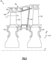
- FIG. 2 schematically illustrates a portion of the turbine section 28.
- the turbine section 28 includes alternating series of rotating blades 102 and stationary vanes 104 that extend into the core flow path C of the gas turbine engine 20.
- Turbine blades 102 rotate and extract energy from the hot combustion gases that are communicated along the core flow path C of the gas turbine engine 20.
- the turbine vanes 104 which generally do not rotate, guide the airflow and prepare it for the next set of blades 102.
- a blade outer air seal (“BOAS”) 106 is positioned slightly radially outwardly of the outer tip of the blades 102.
- BOAS blade outer air seal
- the BOAS 106 is made up of a plurality of BOAS seal segments 105 arranged circumferentially about the axis of rotation A.
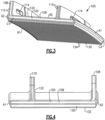
- FIG 3 illustrates an exemplary BOAS seal segment 105.
- Each seal segment 105 is a body that defines radially inner and outer sides R1, R2, respectively, first and second circumferential sides C1, C2, respectively, and first and second axial sides A1, A2, respectively.
- the radially inner side R1 faces in a direction toward the engine central axis A.
- the radially inner side R1 is thus the hotwall or gas path side of the seal segment 105 that bounds a portion of the core flow path C.
- the first axial side A1 faces in a forward direction toward the front of the engine 20 (i.e., toward the fan 42), and the second axial side A2 faces in an aft direction toward the rear of the engine 20 (i.e., toward the exhaust end).
- the BOAS seal segment 105 has attachment members 108 and 110 and a central web 109.
- the attachment members 108, 110 secure the BOAS seal segment 105 to an engine structure, such as the engine static structure 36.
- an engine structure such as the engine static structure 36.
- the BOAS seal segment 105 is formed of a ceramic matrix composite ("CMC") material.
- the BOAS seal segment 105 is formed of a plurality of CMC laminates 122.
- the laminates may be silicon carbide fibers, formed into a woven fabric in each layer.
- the fibers may be coated by a boron nitride.
- the seal segment 105 may have a central reinforcement laminate 120 including a plurality of layers.
- An overwrap 122 also includes a plurality of layers or laminates, and spans a central web 109 which is defined axially between radially extending attachment members 108 and 110, and may extend axially outwardly of one or both attachment members 108, 110.
- attachment members 108, 110 extend radially from the central web and have holes 114 for attachment to the engine structure 36.
- the attachment members 108, 110 may be hooks, for example.
- Other BOAS seal segments 105 and/or structures for attachment of the BOAS seal segment 105 to the engine structure 36 may be contemplated within the scope of this disclosure.
- the BOAS seal segment 105 may be formed from a metallic material or monolithic ceramic, for example.
- the seal segment 105 includes a cavity layer or honeycomb layer 130 and a geometrically segmented abradable coating ("GSAC") 132 on the radially inner side R1.
- GSAC geometrically segmented abradable coating
- An abradable coating on a BOAS seal segment 105 contacts tips of the turbine blades 102 such that the blades 102 abrade the coating upon operation of the engine 20. This provides a minimum clearance between the BOAS seal segment 105 and the tip of the blade 102.
- internal stresses can develop in the coating that may make the coating vulnerable to erosion and spalling. When the coating is spalling, small fragments or chips wear off the BOAS. In some known coatings, the BOAS needs to be replaced after a period of use. The use of a GSAC can help reduce this spalling.
- a GSAC forms segmentation cracks within the coating at corners of the underlying component upon sintering. These segmentation cracks provide locations to accommodate the strain associated with internal stresses. That is, the energy associated with the internal stresses is maintained at a lower level due to the cracks such that there is less energy available for causing delamination cracking and spallation.
- the GSAC is a ceramic material.
- the cavity layer or honeycomb layer 130 has a plurality of cavities 134 that facilitate the cracks in the GSAC 132 for spallation reduction.
- the cavities 134 are all the same size and shape.
- the cavities 134 are evenly spaced from one another and span the entire honeycomb layer 130.
- the GSAC 132 fills each of the cavities 134, and has an additional thickness radially inward of the honeycomb layer 130.
- the GSAC 132 provides a generally smooth radially inner surface for the BOAS seal segment 105. That is, the GSAC 132 provides the hot wall surface immediately adjacent the tips of the turbine blades 102.
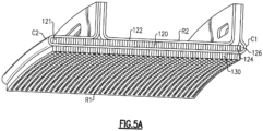
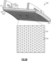
- FIGS 5A and 5B show method steps of forming a BOAS seal segment 105.
- the BOAS seal segment 105 is formed of a ceramic matrix composite ("CMC") material.
- CMC ceramic matrix composite
- a seal body 121 is formed, such as from a plurality of laminates.
- the seal body 121 is formed from a central reinforcement laminate 120 including a plurality of layers and an overwrap 122, which also includes a plurality of laminates.
- a CMC honeycomb layer 130 is added to the radially inner side R1.
- the CMC honeycomb is 3D woven and produced in sheets.
- a CMC honeycomb sheet is then cut to size and applied to the radially inner side R1 of the seal body 121 to form the honeycomb layer 130, as shown in Figure 5A .
- the seal body 121 and CMC honeycomb layer 130 are then densified.
- the CMC honeycomb layer 130 is densified onto the gaspath location on the BOAS seal segment 105.
- a densification process is utilized to increase the density of the laminate material after forming the seal body 121. This makes the laminates more stiff than their free woven fiber state.
- materials such as a silicon carbide matrix material, are injected into spaces between the fibers in the woven layers. Spaces 124 and 126 or the honeycomb layer 130 may be filled with loose fibers during densification, for example.
- This densification process may be utilized to provide 100% of the desired densification, or only some percentage.
- the densification may be utilized to form between 10 and 90% of a desired densification.
- One hundred percent densification may be defined as the layers being completely saturated with the matrix and about the fibers.
- One hundred percent densification may be defined as the theoretical upper limit of layers being completely saturated with the matrix and about the fibers, such that no additional material may be deposited. In practice, 100% may be difficult to achieve.
- This method of densifying the honeycomb layer 130 with the BOAS seal segment 105 allows the honeycomb layer 130 to act as an additional structural layer of the BOAS hotwall and no additional machining steps are necessary to create the cavities 134.
- the abradable coating 132 is applied. In some embodiments, the coating 132 is applied after all machining operations are completed on the seal segment 105. Individual cavities 134 of the honeycomb layer 130 are filled with the abradable coating, and additional abradable coating thickness 132 is applied on the radially inner side R1.
- the honeycomb layer 130 provides a base for the abradable coating to have GSAC properties.
- Known methods of making a BOAS with a GSAC include drilling divots into the BOAS gaspath surface before applying the GSAC.
- the present disclosure eliminates the drilling step, by using a woven honeycomb sheet to form the honeycomb layer 130. Once the cavities 134 are filled with GSAC 132, additional GSAC thickness provides further environmental and thermal protection to the BOAS seal segment 105.
- the honeycomb layer 130 is initially formed as a continuous sheet.
- Figures 6A and 6B illustrate exemplary CMC honeycomb sheets 131.
- the honeycomb sheet 131 has a plurality of hexagonal cavities 134.
- the sheet 131 may be a silicon carbide sheet.
- the sheet 131 is a carbon fiber reinforced silicon carbide composite.
- the sheet 131 may be 3D woven with the honeycomb structure, and may be adapted for chemical vapor infiltration. In other embodiments, the sheet 131 may be woven as a solid CMC sheet, with cavities 134 drilled in.
- each cavity 134 may have a width 136 of between about 0.010 and 0.200 inches (0.254-5.08 mm). In a further example, each cavity 134 has a width 136 of about 0.030 inches (0.762 mm).
- the sheet 131 may have a solidity of between about 20% and about 80%. In some examples, the sheet 131 has about 50% solidity. This means the about 50% of the area is solid structure, while 50% is cavities 134. However, greater or smaller solidities may be used.
- the hexagonal cavities 134 in the honeycomb sheet 131 may provide better spallation-mitigation properties than traditional machined circular divots, as there are additional faces for bonding of the GSAC 132.
- Figure 6B shows an alternative CMC sheet 231.
- the sheet 231 has a plurality of round cavities 234.
- the CMC sheet 231 is a full continuous CMC sheet with cavities 234 drilled in.
- Circular cavities 234 may be easier to manufacture than hexagonal cavities, while still providing faults for segmentation of the GSAC 132.
- Other shaped cavities may also be used, such as rectangular or triangular, for example.
- the honeycomb sheet is lightweight and structural, while providing cavities for insulation, cooling, or void space.
- the honeycomb structure may provide internal, film and/or perspiration cooling.
- the honeycomb sheet 131 provides a base for cracks to propagate with a lower risk of coating spallation.
- the honeycomb structure and GSAC coating may also provide a lower CMC bulk temperature.
Landscapes
- Engineering & Computer Science (AREA)
- Mechanical Engineering (AREA)
- General Engineering & Computer Science (AREA)
- Turbine Rotor Nozzle Sealing (AREA)
Abstract
Description
- This application relates to a blade outer air seal having a unique structure.
- Gas turbine engines are known and typically include a compressor for compressing air and delivering it into a combustor. The air is mixed with fuel in the combustor and ignited. Products of the combustion pass downstream over turbine rotors, driving them to rotate.
- It is desirable to ensure that the bulk of the products of combustion pass over turbine blades on the turbine rotor. As such, it is known to provide blade outer air seals radially outwardly of the blades.
- Blade outer air seals have been proposed made of ceramic matrix composite fiber layers.
- In one aspect, a method of forming a blade outer air seal includes applying a cavity layer that has a plurality of cavities to a radially inner side of a seal body. The cavity layer is coated with an abradable coating.
- In an embodiment of the above, the seal body and cavity layer is densified before coating the cavity layer with the abradable coating.
- In a further embodiment of any of the above, the cavity layer and the seal body are the same material.
- In a further embodiment of any of the above, the seal body and the cavity layer are a ceramic matrix composite material.
- In a further embodiment of any of the above, the cavity layer is formed as a continuous sheet and cut to size before being applied to the seal body.
- In a further embodiment of any of the above, the coating is a geometrically segmented abradable coating formed from a ceramic material.
- In a further embodiment of any of the above, the plurality of cavities is a plurality of hexagonal cavities.
- In a further embodiment of any of the above, the cavity layer has a solidity between about 20% and about 80% or between 20% and 80%.
- In a further embodiment of any of the above, the plurality of cavities is a plurality of circular cavities.
- In a further embodiment of any of the above, the plurality of cavities are evenly spaced over the entire cavity layer.
- In a further embodiment of any of the above, the abradable coating fills each of the plurality of cavities.
- In a further embodiment of any of the above, the abradable coating forms a smooth radially inner surface.
- In a further embodiment of any of the above, the method does not require drilling of the radially inner side of the seal body.
- In a further embodiment of any of the above, the method includes drilling the plurality of cavities into the radially inner side of the seal body.
- In another aspect, a blade outer air seal includes a blade outer air seal body that has a radially inner side and a radially outer side. The radially inner side has a cavity layer that has a plurality of cavities and an abradable coating over the cavity layer.
- In an embodiment of the above, the plurality of cavities is a plurality of hexagonal cavities.
- In a further embodiment of any of the above, the plurality of cavities are evenly spaced over the entire cavity layer and wherein the cavity layer has a solidity between about 20% and about 80%.
- In a further embodiment of any of the above, the abradable coating fills each of the plurality of cavities.
- In a further embodiment of any of the above, the seal body and the cavity layer are both a ceramic matrix composite material.
- In a further embodiment of any of the above, the abradable coating is a geometrically segmented abradable coating formed from a ceramic material.
- These and other features may be best understood from the following drawings and specification.
-
-
Figure 1 schematically shows a gas turbine engine. -
Figure 2 schematically shows a portion of a turbine section. -
Figure 3 shows a blade outer air seal according to exemplary embodiment. -
Figure 4 shows a cross-sectional view through a blade outer air seal. -
Figure 5A shows a method step in forming a blade outer air seal. -
Figure 5B shows a subsequent method step in forming a blade outer air seal. -
Figure 6A shows a honeycomb sheet according to an exemplary embodiment. -
Figure 6B shows a honeycomb sheet according to an exemplary embodiment. -
Figure 1 schematically illustrates agas turbine engine 20. Thegas turbine engine 20 is disclosed herein as a two-spool turbofan that generally incorporates afan section 22, acompressor section 24, acombustor section 26 and aturbine section 28. Thefan section 22 drives air along a bypass flow path B in a bypass duct defined within anacelle 15, and also drives air along a core flow path C for compression and communication into thecombustor section 26 then expansion through theturbine section 28. Although depicted as a two-spool turbofan gas turbine engine in the disclosed non-limiting embodiment, it should be understood that the concepts described herein are not limited to use with two-spool turbofans as the teachings may be applied to other types of turbine engines including three-spool architectures. - The
exemplary engine 20 generally includes alow speed spool 30 and ahigh speed spool 32 mounted for rotation about an engine central longitudinal axis A relative to an enginestatic structure 36 viaseveral bearing systems 38. It should be understood thatvarious bearing systems 38 at various locations may alternatively or additionally be provided, and the location ofbearing systems 38 may be varied as appropriate to the application. - The
low speed spool 30 generally includes aninner shaft 40 that interconnects, a first (or low) pressure compressor 44 and a first (or low)pressure turbine 46. Theinner shaft 40 is connected to thefan 42 through a speed change mechanism, which in exemplarygas turbine engine 20 is illustrated as a gearedarchitecture 48 to drive afan 42 at a lower speed than thelow speed spool 30. Thehigh speed spool 32 includes anouter shaft 50 that interconnects a second (or high)pressure compressor 52 and a second (or high)pressure turbine 54. Acombustor 56 is arranged inexemplary gas turbine 20 between thehigh pressure compressor 52 and thehigh pressure turbine 54. Amid-turbine frame 57 of the enginestatic structure 36 may be arranged generally between thehigh pressure turbine 54 and thelow pressure turbine 46. Themid-turbine frame 57 further supports bearingsystems 38 in theturbine section 28. Theinner shaft 40 and theouter shaft 50 are concentric and rotate viabearing systems 38 about the engine central longitudinal axis A which is collinear with their longitudinal axes. - The core airflow is compressed by the low pressure compressor 44 then the
high pressure compressor 52, mixed and burned with fuel in thecombustor 56, then expanded over thehigh pressure turbine 54 andlow pressure turbine 46. Themid-turbine frame 57 includesairfoils 59 which are in the core airflow path C. Theturbines low speed spool 30 andhigh speed spool 32 in response to the expansion. It will be appreciated that each of the positions of thefan section 22,compressor section 24,combustor section 26,turbine section 28, and fandrive gear system 48 may be varied. For example,gear system 48 may be located aft of the low pressure compressor, or aft of thecombustor section 26 or even aft ofturbine section 28, andfan 42 may be positioned forward or aft of the location ofgear system 48. - The
engine 20 in one example is a high-bypass geared aircraft engine. In a further example, theengine 20 bypass ratio is greater than about six, with an example embodiment being greater than about ten, the gearedarchitecture 48 is an epicyclic gear train, such as a planetary gear system or other gear system, with a gear reduction ratio of greater than about 2.3 and thelow pressure turbine 46 has a pressure ratio that is greater than about five. In one disclosed embodiment, theengine 20 bypass ratio is greater than about ten, the fan diameter is significantly larger than that of the low pressure compressor 44, and thelow pressure turbine 46 has a pressure ratio that is greater than about five.Low pressure turbine 46 pressure ratio is pressure measured prior to inlet oflow pressure turbine 46 as related to the pressure at the outlet of thelow pressure turbine 46 prior to an exhaust nozzle. The gearedarchitecture 48 may be an epicycle gear train, such as a planetary gear system or other gear system, with a gear reduction ratio of greater than about 2.3:1 and less than about 5:1. It should be understood, however, that the above parameters are only exemplary of one embodiment of a geared architecture engine and that the present invention is applicable to other gas turbine engines including direct drive turbofans. - A significant amount of thrust is provided by the bypass flow B due to the high bypass ratio. The
fan section 22 of theengine 20 is designed for a particular flight condition -- typically cruise at about 0.8 Mach and about 35,000 feet (10,668 meters). The flight condition of 0.8 Mach and 35,000 ft (10,668 meters), with the engine at its best fuel consumption - also known as "bucket cruise Thrust Specific Fuel Consumption ('TSFC')" - is the industry standard parameter of lbm of fuel being burned divided by lbf of thrust the engine produces at that minimum point. "Low fan pressure ratio" is the pressure ratio across the fan blade alone, without a Fan Exit Guide Vane ("FEGV") system. The low fan pressure ratio as disclosed herein according to one non-limiting embodiment is less than about 1.45. "Low corrected fan tip speed" is the actual fan tip speed in ft/sec divided by an industry standard temperature correction of [(Tram °R) / (518.7 °R)]0.5 (where °R = K x 9/5). The "Low corrected fan tip speed" as disclosed herein according to one non-limiting embodiment is less than about 1150 ft / second (350.5 meters/second). -
Figure 2 schematically illustrates a portion of theturbine section 28. Theturbine section 28 includes alternating series ofrotating blades 102 andstationary vanes 104 that extend into the core flow path C of thegas turbine engine 20.Turbine blades 102 rotate and extract energy from the hot combustion gases that are communicated along the core flow path C of thegas turbine engine 20. Theturbine vanes 104, which generally do not rotate, guide the airflow and prepare it for the next set ofblades 102. As is known, it is desirable to pass the bulk of products of combustion downstream of thecombustor section 26 across theturbine blades 102. Thus, a blade outer air seal ("BOAS") 106 is positioned slightly radially outwardly of the outer tip of theblades 102. It should be understood that theturbine section 28 could be utilized in other gas turbine engines, and even gas turbine engines not having a fan section at all. TheBOAS 106 is made up of a plurality ofBOAS seal segments 105 arranged circumferentially about the axis of rotation A. -
Figure 3 illustrates an exemplaryBOAS seal segment 105. Eachseal segment 105 is a body that defines radially inner and outer sides R1, R2, respectively, first and second circumferential sides C1, C2, respectively, and first and second axial sides A1, A2, respectively. The radially inner side R1 faces in a direction toward the engine central axis A. The radially inner side R1 is thus the hotwall or gas path side of theseal segment 105 that bounds a portion of the core flow path C. The first axial side A1 faces in a forward direction toward the front of the engine 20 (i.e., toward the fan 42), and the second axial side A2 faces in an aft direction toward the rear of the engine 20 (i.e., toward the exhaust end). - As shown in
Figure 4 and with continuing reference toFigure 3 , theBOAS seal segment 105 hasattachment members central web 109. Theattachment members BOAS seal segment 105 to an engine structure, such as the enginestatic structure 36. Although a particularBOAS seal segment 105 is shown, this disclosure may apply to other BOAS or attachment configurations. - In the illustrated embodiment, the
BOAS seal segment 105 is formed of a ceramic matrix composite ("CMC") material. TheBOAS seal segment 105 is formed of a plurality of CMC laminates 122. The laminates may be silicon carbide fibers, formed into a woven fabric in each layer. The fibers may be coated by a boron nitride. - In one embodiment, the
seal segment 105 may have acentral reinforcement laminate 120 including a plurality of layers. Anoverwrap 122 also includes a plurality of layers or laminates, and spans acentral web 109 which is defined axially between radially extendingattachment members attachment members attachment members holes 114 for attachment to theengine structure 36. In other embodiments, theattachment members BOAS seal segments 105 and/or structures for attachment of theBOAS seal segment 105 to theengine structure 36 may be contemplated within the scope of this disclosure. In other embodiments, theBOAS seal segment 105 may be formed from a metallic material or monolithic ceramic, for example. - The
seal segment 105 includes a cavity layer orhoneycomb layer 130 and a geometrically segmented abradable coating ("GSAC") 132 on the radially inner side R1. An abradable coating on aBOAS seal segment 105 contacts tips of theturbine blades 102 such that theblades 102 abrade the coating upon operation of theengine 20. This provides a minimum clearance between theBOAS seal segment 105 and the tip of theblade 102. Over time, internal stresses can develop in the coating that may make the coating vulnerable to erosion and spalling. When the coating is spalling, small fragments or chips wear off the BOAS. In some known coatings, the BOAS needs to be replaced after a period of use. The use of a GSAC can help reduce this spalling. A GSAC forms segmentation cracks within the coating at corners of the underlying component upon sintering. These segmentation cracks provide locations to accommodate the strain associated with internal stresses. That is, the energy associated with the internal stresses is maintained at a lower level due to the cracks such that there is less energy available for causing delamination cracking and spallation. In one embodiment, the GSAC is a ceramic material. - The cavity layer or
honeycomb layer 130 has a plurality ofcavities 134 that facilitate the cracks in theGSAC 132 for spallation reduction. In an example embodiment, thecavities 134 are all the same size and shape. In an embodiment, thecavities 134 are evenly spaced from one another and span theentire honeycomb layer 130. TheGSAC 132 fills each of thecavities 134, and has an additional thickness radially inward of thehoneycomb layer 130. In one example, theGSAC 132 provides a generally smooth radially inner surface for theBOAS seal segment 105. That is, theGSAC 132 provides the hot wall surface immediately adjacent the tips of theturbine blades 102. -
Figures 5A and5B show method steps of forming aBOAS seal segment 105. TheBOAS seal segment 105 is formed of a ceramic matrix composite ("CMC") material. First, aseal body 121 is formed, such as from a plurality of laminates. In some embodiments, theseal body 121 is formed from acentral reinforcement laminate 120 including a plurality of layers and anoverwrap 122, which also includes a plurality of laminates. Next, aCMC honeycomb layer 130 is added to the radially inner side R1. The CMC honeycomb is 3D woven and produced in sheets. A CMC honeycomb sheet is then cut to size and applied to the radially inner side R1 of theseal body 121 to form thehoneycomb layer 130, as shown inFigure 5A . Theseal body 121 andCMC honeycomb layer 130 are then densified. TheCMC honeycomb layer 130 is densified onto the gaspath location on theBOAS seal segment 105. - A densification process is utilized to increase the density of the laminate material after forming the
seal body 121. This makes the laminates more stiff than their free woven fiber state. During densification, materials, such as a silicon carbide matrix material, are injected into spaces between the fibers in the woven layers.Spaces honeycomb layer 130 may be filled with loose fibers during densification, for example. - This densification process may be utilized to provide 100% of the desired densification, or only some percentage. As an example, the densification may be utilized to form between 10 and 90% of a desired densification. One hundred percent densification may be defined as the layers being completely saturated with the matrix and about the fibers. One hundred percent densification may be defined as the theoretical upper limit of layers being completely saturated with the matrix and about the fibers, such that no additional material may be deposited. In practice, 100% may be difficult to achieve. This method of densifying the
honeycomb layer 130 with theBOAS seal segment 105 allows thehoneycomb layer 130 to act as an additional structural layer of the BOAS hotwall and no additional machining steps are necessary to create thecavities 134. - After the
seal body 121 andCMC honeycomb layer 130 have been densified, theabradable coating 132 is applied. In some embodiments, thecoating 132 is applied after all machining operations are completed on theseal segment 105.Individual cavities 134 of thehoneycomb layer 130 are filled with the abradable coating, and additionalabradable coating thickness 132 is applied on the radially inner side R1. Thehoneycomb layer 130 provides a base for the abradable coating to have GSAC properties. - Known methods of making a BOAS with a GSAC include drilling divots into the BOAS gaspath surface before applying the GSAC. The present disclosure eliminates the drilling step, by using a woven honeycomb sheet to form the
honeycomb layer 130. Once thecavities 134 are filled withGSAC 132, additional GSAC thickness provides further environmental and thermal protection to theBOAS seal segment 105. - The
honeycomb layer 130 is initially formed as a continuous sheet.Figures 6A and 6B illustrate exemplaryCMC honeycomb sheets 131. As shown inFigure 6A , thehoneycomb sheet 131 has a plurality ofhexagonal cavities 134. Thesheet 131 may be a silicon carbide sheet. In some examples, thesheet 131 is a carbon fiber reinforced silicon carbide composite. Thesheet 131 may be 3D woven with the honeycomb structure, and may be adapted for chemical vapor infiltration. In other embodiments, thesheet 131 may be woven as a solid CMC sheet, withcavities 134 drilled in. - In some examples, each
cavity 134 may have awidth 136 of between about 0.010 and 0.200 inches (0.254-5.08 mm). In a further example, eachcavity 134 has awidth 136 of about 0.030 inches (0.762 mm). Thesheet 131 may have a solidity of between about 20% and about 80%. In some examples, thesheet 131 has about 50% solidity. This means the about 50% of the area is solid structure, while 50% iscavities 134. However, greater or smaller solidities may be used. Thehexagonal cavities 134 in thehoneycomb sheet 131 may provide better spallation-mitigation properties than traditional machined circular divots, as there are additional faces for bonding of theGSAC 132. -
Figure 6B shows analternative CMC sheet 231. In this example, thesheet 231 has a plurality ofround cavities 234. In some embodiments, theCMC sheet 231 is a full continuous CMC sheet withcavities 234 drilled in.Circular cavities 234 may be easier to manufacture than hexagonal cavities, while still providing faults for segmentation of theGSAC 132. Other shaped cavities may also be used, such as rectangular or triangular, for example. - The honeycomb sheet is lightweight and structural, while providing cavities for insulation, cooling, or void space. The honeycomb structure may provide internal, film and/or perspiration cooling. The
honeycomb sheet 131 provides a base for cracks to propagate with a lower risk of coating spallation. The honeycomb structure and GSAC coating may also provide a lower CMC bulk temperature. - Although an embodiment of this invention has been disclosed, a worker of ordinary skill in this art would recognize that certain modifications would come within the scope of this disclosure. For that reason, the following claims should be studied to determine the true scope and content of this disclosure.
Claims (15)
- A blade outer air seal (106), comprising:
a blade outer air seal body (121) having a radially inner side (R1) and a radially outer side (R2), wherein the radially inner side (R1) has a cavity layer (130) having a plurality of cavities (134; 234) and an abradable coating (132) over the cavity layer (130). - A method of forming a blade outer air seal (106), comprising:applying a cavity layer (130) having a plurality of cavities (134; 234) to a radially inner side (R1) of a seal body (121); andcoating the cavity layer (130) with an abradable coating (132).
- The method or blade outer air seal of claim 1 or 2, wherein the plurality of cavities (234) is a plurality of circular cavities (234).
- The method or blade outer air seal of claim 1 or 2, wherein the plurality of cavities (134) is a plurality of hexagonal cavities (134).
- The method or blade outer air seal of any preceding claim, wherein the plurality of cavities (134; 234) are evenly spaced over the entire cavity layer (130).
- The method or blade outer air seal of any preceding claim, wherein the cavity layer (130) has a solidity between about 20% and about 80%.
- The method or blade outer air seal of any preceding claim, wherein the abradable coating (132) fills each of the plurality of cavities (134; 234).
- The method or blade outer air seal of any preceding claim, wherein the seal body (121) and the cavity layer (130) are both a ceramic matrix composite material.
- The method or blade outer air seal of any preceding claim, wherein the abradable coating (132) is a geometrically segmented abradable coating (132) formed from a ceramic material.
- The method of any preceding claim, comprising densifying the seal body (121) and cavity layer (130) before coating the cavity layer (130) with the abradable coating (132).
- The method of any preceding claim, wherein the cavity layer (130) and the seal body (121) are the same material.
- The method of any preceding claim, wherein the cavity layer (130) is formed as a continuous sheet and is cut to size before being applied to the seal body (121).
- The method of any preceding claim, wherein the abradable coating (132) forms a smooth radially inner surface.
- The method of any preceding claim, wherein the method does not require drilling of the radially inner side of the seal body (121).
- The method of any of claims 1 to 13, wherein the method includes drilling the plurality of cavities into the radially inner side of the seal body (121).
Applications Claiming Priority (2)
| Application Number | Priority Date | Filing Date | Title |
|---|---|---|---|
| US16/207,918 US11187100B2 (en) | 2018-12-03 | 2018-12-03 | CMC honeycomb base for abradable coating on CMC BOAS |
| EP19213267.8A EP3663533B1 (en) | 2018-12-03 | 2019-12-03 | Method of forming a boas |
Related Parent Applications (1)
| Application Number | Title | Priority Date | Filing Date |
|---|---|---|---|
| EP19213267.8A Division EP3663533B1 (en) | 2018-12-03 | 2019-12-03 | Method of forming a boas |
Publications (2)
| Publication Number | Publication Date |
|---|---|
| EP4219910A1 true EP4219910A1 (en) | 2023-08-02 |
| EP4219910B1 EP4219910B1 (en) | 2025-02-12 |
Family
ID=68766689
Family Applications (2)
| Application Number | Title | Priority Date | Filing Date |
|---|---|---|---|
| EP23166176.0A Active EP4219910B1 (en) | 2018-12-03 | 2019-12-03 | Cmc honeycomb base for abradable coating on cmc boas |
| EP19213267.8A Active EP3663533B1 (en) | 2018-12-03 | 2019-12-03 | Method of forming a boas |
Family Applications After (1)
| Application Number | Title | Priority Date | Filing Date |
|---|---|---|---|
| EP19213267.8A Active EP3663533B1 (en) | 2018-12-03 | 2019-12-03 | Method of forming a boas |
Country Status (2)
| Country | Link |
|---|---|
| US (1) | US11187100B2 (en) |
| EP (2) | EP4219910B1 (en) |
Families Citing this family (6)
| Publication number | Priority date | Publication date | Assignee | Title |
|---|---|---|---|---|
| US10934878B2 (en) * | 2018-12-05 | 2021-03-02 | Raytheon Technologies Corporation | CMC loop boas |
| FR3111941B1 (en) * | 2020-06-29 | 2025-03-21 | Safran Aircraft Engines | CASING FOR AN AIRCRAFT TURBOMACHINE |
| US11732598B2 (en) * | 2021-12-17 | 2023-08-22 | Rolls-Royce Corporation | Ceramic matrix composite turbine shroud shaped for minimizing abradable coating layer |
| US11913340B2 (en) | 2022-06-17 | 2024-02-27 | Rtx Corporation | Air seal system with backside abradable layer |
| US12467629B1 (en) * | 2025-01-15 | 2025-11-11 | Rtx Corporation | CMC component with cover plate |
| US12613034B1 (en) * | 2025-01-29 | 2026-04-28 | Rtx Corporation | Ceramic matrix composite component with corrugated wall |
Citations (4)
| Publication number | Priority date | Publication date | Assignee | Title |
|---|---|---|---|---|
| EP2325347A1 (en) * | 2009-11-19 | 2011-05-25 | United Technologies Corporation | Segmented thermally insulating coating |
| WO2011085376A1 (en) * | 2010-01-11 | 2011-07-14 | Rolls-Royce Corporation | Features for mitigating thermal or mechanical stress on an environmental barrier coating |
| US20160040551A1 (en) * | 2014-08-06 | 2016-02-11 | United Technologies Corporation | Geometrically segmented coating on contoured surfaces |
| US20180066527A1 (en) * | 2015-02-18 | 2018-03-08 | Siemens Aktiengesellschaft | Turbine component thermal barrier coating with vertically aligned, engineered surface and multifurcated groove features |
Family Cites Families (12)
| Publication number | Priority date | Publication date | Assignee | Title |
|---|---|---|---|---|
| FR2817994B1 (en) | 2000-12-08 | 2003-02-28 | Eads Airbus Sa | SANDWICH ACOUSTIC PANEL |
| US7550189B1 (en) | 2004-08-13 | 2009-06-23 | Hrl Laboratories, Llc | Variable stiffness structure |
| DE102006016147A1 (en) * | 2006-04-06 | 2007-10-11 | Mtu Aero Engines Gmbh | Method for producing a honeycomb seal |
| US7819625B2 (en) | 2007-05-07 | 2010-10-26 | Siemens Energy, Inc. | Abradable CMC stacked laminate ring segment for a gas turbine |
| EP3058183B1 (en) | 2013-10-02 | 2019-02-27 | United Technologies Corporation | Segmented ceramic coating interlayer |
| US10443444B2 (en) * | 2014-05-21 | 2019-10-15 | United Technologies Corporation | Cost effective manufacturing method for GSAC incorporating a stamped preform |
| EP3029274B1 (en) | 2014-10-30 | 2020-03-11 | United Technologies Corporation | Thermal-sprayed bonding of a ceramic structure to a substrate |
| US9755819B2 (en) | 2015-07-01 | 2017-09-05 | Rambus Inc. | Phase calibration of clock signals |
| US10711624B2 (en) | 2016-11-17 | 2020-07-14 | Raytheon Technologies Corporation | Airfoil with geometrically segmented coating section |
| US10711794B2 (en) | 2016-11-17 | 2020-07-14 | Raytheon Technologies Corporation | Airfoil with geometrically segmented coating section having mechanical secondary bonding feature |
| US10480331B2 (en) | 2016-11-17 | 2019-11-19 | United Technologies Corporation | Airfoil having panel with geometrically segmented coating |
| US11261750B2 (en) * | 2018-03-26 | 2022-03-01 | Rolls-Royce North American Technologies Inc. | CMC blade track with integral abradable |
-
2018
- 2018-12-03 US US16/207,918 patent/US11187100B2/en active Active
-
2019
- 2019-12-03 EP EP23166176.0A patent/EP4219910B1/en active Active
- 2019-12-03 EP EP19213267.8A patent/EP3663533B1/en active Active
Patent Citations (4)
| Publication number | Priority date | Publication date | Assignee | Title |
|---|---|---|---|---|
| EP2325347A1 (en) * | 2009-11-19 | 2011-05-25 | United Technologies Corporation | Segmented thermally insulating coating |
| WO2011085376A1 (en) * | 2010-01-11 | 2011-07-14 | Rolls-Royce Corporation | Features for mitigating thermal or mechanical stress on an environmental barrier coating |
| US20160040551A1 (en) * | 2014-08-06 | 2016-02-11 | United Technologies Corporation | Geometrically segmented coating on contoured surfaces |
| US20180066527A1 (en) * | 2015-02-18 | 2018-03-08 | Siemens Aktiengesellschaft | Turbine component thermal barrier coating with vertically aligned, engineered surface and multifurcated groove features |
Also Published As
| Publication number | Publication date |
|---|---|
| EP3663533B1 (en) | 2023-04-12 |
| US11187100B2 (en) | 2021-11-30 |
| EP4219910B1 (en) | 2025-02-12 |
| EP3663533A1 (en) | 2020-06-10 |
| US20200173299A1 (en) | 2020-06-04 |
Similar Documents
| Publication | Publication Date | Title |
|---|---|---|
| EP3819477B1 (en) | Feather seal slot arrangement for a cmc blade outer air seal assembly | |
| EP3663533B1 (en) | Method of forming a boas | |
| US11125096B2 (en) | CMC boas arrangement | |
| US11319827B2 (en) | Intersegment seal for blade outer air seal | |
| US11255208B2 (en) | Feather seal for CMC BOAS | |
| EP3626934A1 (en) | Turbine section comprising a featherseal formed of cmc material | |
| EP3626427A2 (en) | Constant cross section mandrel for cmc components | |
| EP3613951B1 (en) | Blade outer air seal with circumferential hook assembly | |
| EP3617459B1 (en) | Method of forming a gas turbine component formed of laminate | |
| EP3628824A1 (en) | Blade outer air seal laminate t-joint | |
| US12123307B2 (en) | Air seal system with backside abradable layer | |
| US11073037B2 (en) | CMC BOAS arrangement | |
| US20210017872A1 (en) | Cmc boas arrangement | |
| EP3608513B1 (en) | Blade outer air seal reinforcement laminate | |
| US11242991B2 (en) | CMC component arrangement and method of manufacture | |
| EP3712384A1 (en) | Blade outer air seal with seal carrier | |
| US11098608B2 (en) | CMC BOAS with internal support structure | |
| EP3736410A1 (en) | Nesting components | |
| EP3708784A1 (en) | Boas carrier with cooling supply | |
| EP3660275B1 (en) | Abradable coating for grooved boas | |
| EP3712383A1 (en) | Cmc blade outer air seal |
Legal Events
| Date | Code | Title | Description |
|---|---|---|---|
| PUAI | Public reference made under article 153(3) epc to a published international application that has entered the european phase |
Free format text: ORIGINAL CODE: 0009012 |
|
| STAA | Information on the status of an ep patent application or granted ep patent |
Free format text: STATUS: THE APPLICATION HAS BEEN PUBLISHED |
|
| AC | Divisional application: reference to earlier application |
Ref document number: 3663533 Country of ref document: EP Kind code of ref document: P |
|
| AK | Designated contracting states |
Kind code of ref document: A1 Designated state(s): AL AT BE BG CH CY CZ DE DK EE ES FI FR GB GR HR HU IE IS IT LI LT LU LV MC MK MT NL NO PL PT RO RS SE SI SK SM TR |
|
| RAP3 | Party data changed (applicant data changed or rights of an application transferred) |
Owner name: RTX CORPORATION |
|
| STAA | Information on the status of an ep patent application or granted ep patent |
Free format text: STATUS: REQUEST FOR EXAMINATION WAS MADE |
|
| 17P | Request for examination filed |
Effective date: 20240202 |
|
| RBV | Designated contracting states (corrected) |
Designated state(s): AL AT BE BG CH CY CZ DE DK EE ES FI FR GB GR HR HU IE IS IT LI LT LU LV MC MK MT NL NO PL PT RO RS SE SI SK SM TR |
|
| GRAP | Despatch of communication of intention to grant a patent |
Free format text: ORIGINAL CODE: EPIDOSNIGR1 |
|
| STAA | Information on the status of an ep patent application or granted ep patent |
Free format text: STATUS: GRANT OF PATENT IS INTENDED |
|
| RIC1 | Information provided on ipc code assigned before grant |
Ipc: F01D 11/12 20060101AFI20240802BHEP |
|
| INTG | Intention to grant announced |
Effective date: 20240906 |
|
| GRAS | Grant fee paid |
Free format text: ORIGINAL CODE: EPIDOSNIGR3 |
|
| GRAA | (expected) grant |
Free format text: ORIGINAL CODE: 0009210 |
|
| STAA | Information on the status of an ep patent application or granted ep patent |
Free format text: STATUS: THE PATENT HAS BEEN GRANTED |
|
| AC | Divisional application: reference to earlier application |
Ref document number: 3663533 Country of ref document: EP Kind code of ref document: P |
|
| AK | Designated contracting states |
Kind code of ref document: B1 Designated state(s): AL AT BE BG CH CY CZ DE DK EE ES FI FR GB GR HR HU IE IS IT LI LT LU LV MC MK MT NL NO PL PT RO RS SE SI SK SM TR |
|
| REG | Reference to a national code |
Ref country code: GB Ref legal event code: FG4D |
|
| REG | Reference to a national code |
Ref country code: CH Ref legal event code: EP |
|
| REG | Reference to a national code |
Ref country code: DE Ref legal event code: R096 Ref document number: 602019066031 Country of ref document: DE |
|
| REG | Reference to a national code |
Ref country code: IE Ref legal event code: FG4D |
|
| REG | Reference to a national code |
Ref country code: NL Ref legal event code: MP Effective date: 20250212 |
|
| PG25 | Lapsed in a contracting state [announced via postgrant information from national office to epo] |
Ref country code: RS Free format text: LAPSE BECAUSE OF FAILURE TO SUBMIT A TRANSLATION OF THE DESCRIPTION OR TO PAY THE FEE WITHIN THE PRESCRIBED TIME-LIMIT Effective date: 20250512 |
|
| PG25 | Lapsed in a contracting state [announced via postgrant information from national office to epo] |
Ref country code: FI Free format text: LAPSE BECAUSE OF FAILURE TO SUBMIT A TRANSLATION OF THE DESCRIPTION OR TO PAY THE FEE WITHIN THE PRESCRIBED TIME-LIMIT Effective date: 20250212 |
|
| PG25 | Lapsed in a contracting state [announced via postgrant information from national office to epo] |
Ref country code: PL Free format text: LAPSE BECAUSE OF FAILURE TO SUBMIT A TRANSLATION OF THE DESCRIPTION OR TO PAY THE FEE WITHIN THE PRESCRIBED TIME-LIMIT Effective date: 20250212 |
|
| PG25 | Lapsed in a contracting state [announced via postgrant information from national office to epo] |
Ref country code: ES Free format text: LAPSE BECAUSE OF FAILURE TO SUBMIT A TRANSLATION OF THE DESCRIPTION OR TO PAY THE FEE WITHIN THE PRESCRIBED TIME-LIMIT Effective date: 20250212 |
|
| REG | Reference to a national code |
Ref country code: LT Ref legal event code: MG9D |
|
| PG25 | Lapsed in a contracting state [announced via postgrant information from national office to epo] |
Ref country code: IS Free format text: LAPSE BECAUSE OF FAILURE TO SUBMIT A TRANSLATION OF THE DESCRIPTION OR TO PAY THE FEE WITHIN THE PRESCRIBED TIME-LIMIT Effective date: 20250612 Ref country code: NO Free format text: LAPSE BECAUSE OF FAILURE TO SUBMIT A TRANSLATION OF THE DESCRIPTION OR TO PAY THE FEE WITHIN THE PRESCRIBED TIME-LIMIT Effective date: 20250512 |
|
| PG25 | Lapsed in a contracting state [announced via postgrant information from national office to epo] |
Ref country code: NL Free format text: LAPSE BECAUSE OF FAILURE TO SUBMIT A TRANSLATION OF THE DESCRIPTION OR TO PAY THE FEE WITHIN THE PRESCRIBED TIME-LIMIT Effective date: 20250212 |
|
| PG25 | Lapsed in a contracting state [announced via postgrant information from national office to epo] |
Ref country code: HR Free format text: LAPSE BECAUSE OF FAILURE TO SUBMIT A TRANSLATION OF THE DESCRIPTION OR TO PAY THE FEE WITHIN THE PRESCRIBED TIME-LIMIT Effective date: 20250212 |
|
| PG25 | Lapsed in a contracting state [announced via postgrant information from national office to epo] |
Ref country code: PT Free format text: LAPSE BECAUSE OF FAILURE TO SUBMIT A TRANSLATION OF THE DESCRIPTION OR TO PAY THE FEE WITHIN THE PRESCRIBED TIME-LIMIT Effective date: 20250612 Ref country code: LV Free format text: LAPSE BECAUSE OF FAILURE TO SUBMIT A TRANSLATION OF THE DESCRIPTION OR TO PAY THE FEE WITHIN THE PRESCRIBED TIME-LIMIT Effective date: 20250212 |
|
| PG25 | Lapsed in a contracting state [announced via postgrant information from national office to epo] |
Ref country code: BG Free format text: LAPSE BECAUSE OF FAILURE TO SUBMIT A TRANSLATION OF THE DESCRIPTION OR TO PAY THE FEE WITHIN THE PRESCRIBED TIME-LIMIT Effective date: 20250212 Ref country code: GR Free format text: LAPSE BECAUSE OF FAILURE TO SUBMIT A TRANSLATION OF THE DESCRIPTION OR TO PAY THE FEE WITHIN THE PRESCRIBED TIME-LIMIT Effective date: 20250513 |
|
| REG | Reference to a national code |
Ref country code: AT Ref legal event code: MK05 Ref document number: 1766207 Country of ref document: AT Kind code of ref document: T Effective date: 20250212 |
|
| PG25 | Lapsed in a contracting state [announced via postgrant information from national office to epo] |
Ref country code: SE Free format text: LAPSE BECAUSE OF FAILURE TO SUBMIT A TRANSLATION OF THE DESCRIPTION OR TO PAY THE FEE WITHIN THE PRESCRIBED TIME-LIMIT Effective date: 20250212 |
|
| PG25 | Lapsed in a contracting state [announced via postgrant information from national office to epo] |
Ref country code: SM Free format text: LAPSE BECAUSE OF FAILURE TO SUBMIT A TRANSLATION OF THE DESCRIPTION OR TO PAY THE FEE WITHIN THE PRESCRIBED TIME-LIMIT Effective date: 20250212 |
|
| PG25 | Lapsed in a contracting state [announced via postgrant information from national office to epo] |
Ref country code: DK Free format text: LAPSE BECAUSE OF FAILURE TO SUBMIT A TRANSLATION OF THE DESCRIPTION OR TO PAY THE FEE WITHIN THE PRESCRIBED TIME-LIMIT Effective date: 20250212 |
|
| PG25 | Lapsed in a contracting state [announced via postgrant information from national office to epo] |
Ref country code: IT Free format text: LAPSE BECAUSE OF FAILURE TO SUBMIT A TRANSLATION OF THE DESCRIPTION OR TO PAY THE FEE WITHIN THE PRESCRIBED TIME-LIMIT Effective date: 20250212 |
|
| PG25 | Lapsed in a contracting state [announced via postgrant information from national office to epo] |
Ref country code: AT Free format text: LAPSE BECAUSE OF FAILURE TO SUBMIT A TRANSLATION OF THE DESCRIPTION OR TO PAY THE FEE WITHIN THE PRESCRIBED TIME-LIMIT Effective date: 20250212 |
|
| PG25 | Lapsed in a contracting state [announced via postgrant information from national office to epo] |
Ref country code: EE Free format text: LAPSE BECAUSE OF FAILURE TO SUBMIT A TRANSLATION OF THE DESCRIPTION OR TO PAY THE FEE WITHIN THE PRESCRIBED TIME-LIMIT Effective date: 20250212 Ref country code: CZ Free format text: LAPSE BECAUSE OF FAILURE TO SUBMIT A TRANSLATION OF THE DESCRIPTION OR TO PAY THE FEE WITHIN THE PRESCRIBED TIME-LIMIT Effective date: 20250212 |
|
| PG25 | Lapsed in a contracting state [announced via postgrant information from national office to epo] |
Ref country code: RO Free format text: LAPSE BECAUSE OF FAILURE TO SUBMIT A TRANSLATION OF THE DESCRIPTION OR TO PAY THE FEE WITHIN THE PRESCRIBED TIME-LIMIT Effective date: 20250212 |
|
| PG25 | Lapsed in a contracting state [announced via postgrant information from national office to epo] |
Ref country code: SK Free format text: LAPSE BECAUSE OF FAILURE TO SUBMIT A TRANSLATION OF THE DESCRIPTION OR TO PAY THE FEE WITHIN THE PRESCRIBED TIME-LIMIT Effective date: 20250212 |
|
| REG | Reference to a national code |
Ref country code: DE Ref legal event code: R097 Ref document number: 602019066031 Country of ref document: DE |
|
| PLBE | No opposition filed within time limit |
Free format text: ORIGINAL CODE: 0009261 |
|
| STAA | Information on the status of an ep patent application or granted ep patent |
Free format text: STATUS: NO OPPOSITION FILED WITHIN TIME LIMIT |
|
| PGFP | Annual fee paid to national office [announced via postgrant information from national office to epo] |
Ref country code: DE Payment date: 20251126 Year of fee payment: 7 |
|
| PGFP | Annual fee paid to national office [announced via postgrant information from national office to epo] |
Ref country code: GB Payment date: 20251119 Year of fee payment: 7 |
|
| PGFP | Annual fee paid to national office [announced via postgrant information from national office to epo] |
Ref country code: FR Payment date: 20251120 Year of fee payment: 7 |
|
| 26N | No opposition filed |
Effective date: 20251113 |