EP4219837A1 - Method for tilting construction and tilting structure - Google Patents
Method for tilting construction and tilting structure Download PDFInfo
- Publication number
- EP4219837A1 EP4219837A1 EP23152147.7A EP23152147A EP4219837A1 EP 4219837 A1 EP4219837 A1 EP 4219837A1 EP 23152147 A EP23152147 A EP 23152147A EP 4219837 A1 EP4219837 A1 EP 4219837A1
- Authority
- EP
- European Patent Office
- Prior art keywords
- construction
- tilting
- water
- towing
- floating
- Prior art date
- Legal status (The legal status is an assumption and is not a legal conclusion. Google has not performed a legal analysis and makes no representation as to the accuracy of the status listed.)
- Granted
Links
Images






Classifications
-
- E—FIXED CONSTRUCTIONS
- E02—HYDRAULIC ENGINEERING; FOUNDATIONS; SOIL SHIFTING
- E02B—HYDRAULIC ENGINEERING
- E02B17/00—Artificial islands mounted on piles or like supports, e.g. platforms on raisable legs or offshore constructions; Construction methods therefor
- E02B17/04—Equipment specially adapted for raising, lowering, or immobilising the working platform relative to the supporting construction
-
- B—PERFORMING OPERATIONS; TRANSPORTING
- B23—MACHINE TOOLS; METAL-WORKING NOT OTHERWISE PROVIDED FOR
- B23D—PLANING; SLOTTING; SHEARING; BROACHING; SAWING; FILING; SCRAPING; LIKE OPERATIONS FOR WORKING METAL BY REMOVING MATERIAL, NOT OTHERWISE PROVIDED FOR
- B23D57/00—Sawing machines or sawing devices not covered by one of the preceding groups B23D45/00 - B23D55/00
- B23D57/0084—Sawing machines or sawing devices not covered by one of the preceding groups B23D45/00 - B23D55/00 specially adapted for sawing under water or at places accessible with difficulty
-
- E—FIXED CONSTRUCTIONS
- E02—HYDRAULIC ENGINEERING; FOUNDATIONS; SOIL SHIFTING
- E02B—HYDRAULIC ENGINEERING
- E02B17/00—Artificial islands mounted on piles or like supports, e.g. platforms on raisable legs or offshore constructions; Construction methods therefor
- E02B17/02—Artificial islands mounted on piles or like supports, e.g. platforms on raisable legs or offshore constructions; Construction methods therefor placed by lowering the supporting construction to the bottom, e.g. with subsequent fixing thereto
-
- E—FIXED CONSTRUCTIONS
- E02—HYDRAULIC ENGINEERING; FOUNDATIONS; SOIL SHIFTING
- E02B—HYDRAULIC ENGINEERING
- E02B17/00—Artificial islands mounted on piles or like supports, e.g. platforms on raisable legs or offshore constructions; Construction methods therefor
- E02B2017/0052—Removal or dismantling of offshore structures from their offshore location
-
- Y—GENERAL TAGGING OF NEW TECHNOLOGICAL DEVELOPMENTS; GENERAL TAGGING OF CROSS-SECTIONAL TECHNOLOGIES SPANNING OVER SEVERAL SECTIONS OF THE IPC; TECHNICAL SUBJECTS COVERED BY FORMER USPC CROSS-REFERENCE ART COLLECTIONS [XRACs] AND DIGESTS
- Y02—TECHNOLOGIES OR APPLICATIONS FOR MITIGATION OR ADAPTATION AGAINST CLIMATE CHANGE
- Y02E—REDUCTION OF GREENHOUSE GAS [GHG] EMISSIONS, RELATED TO ENERGY GENERATION, TRANSMISSION OR DISTRIBUTION
- Y02E10/00—Energy generation through renewable energy sources
- Y02E10/70—Wind energy
- Y02E10/72—Wind turbines with rotation axis in wind direction
-
- Y—GENERAL TAGGING OF NEW TECHNOLOGICAL DEVELOPMENTS; GENERAL TAGGING OF CROSS-SECTIONAL TECHNOLOGIES SPANNING OVER SEVERAL SECTIONS OF THE IPC; TECHNICAL SUBJECTS COVERED BY FORMER USPC CROSS-REFERENCE ART COLLECTIONS [XRACs] AND DIGESTS
- Y02—TECHNOLOGIES OR APPLICATIONS FOR MITIGATION OR ADAPTATION AGAINST CLIMATE CHANGE
- Y02E—REDUCTION OF GREENHOUSE GAS [GHG] EMISSIONS, RELATED TO ENERGY GENERATION, TRANSMISSION OR DISTRIBUTION
- Y02E10/00—Energy generation through renewable energy sources
- Y02E10/70—Wind energy
- Y02E10/727—Offshore wind turbines
Definitions
- the present disclosure relates to a method for tilting a construction and a tilting structure.
- a method of cutting, on the base side, collapsing, and then demolishing the construction is considered as an inexpensive demolishing method that avoids high-place work as much as possible (for example, Japanese Patent No. 4828314 ).
- Cutting of a construction is performed by using explosion or other mechanical cutting, for example.
- Japanese Patent No. 4828314 is an example of the related art.
- the present disclosure has been made in view of such circumstances and intends to provide a method for tilting a construction and a tilting structure that can control at least one of the tilting speed and the tilting direction of the construction.
- the method for tilting a construction and the tilting structure of the present disclosure employ the following solution.
- a method for tilting a construction is a method for tilting a construction to tilt a bottom-mounted construction extending upward from a ground, and the method includes: an installation step of mounting a resistive member to the construction, the resistive member being subjected to fluid force from a fluid surrounding the construction; and a tilting step of tilting the construction to which the resistive member is mounted.
- a tilting structure includes: a bottom-mounted construction extending upward from a ground; and a resistive member mounted to the construction and subjected to fluid force from a fluid surrounding the construction.
- the tilting method and the tilting structure according to each embodiment of the present disclosure are a method and a structure used when a construction 200 is demolished.
- ground 401 is a term including not only land but also a bottom of water such as a sea bed or a lake bed. In each embodiment described below, when the type of the ground 401 is not particularly referred to, the ground 401 can include land and a bottom of water.
- the construction 200 is a bottom-mounted construction extending perpendicularly upward from the ground 401 (that is, having a longitudinal direction in the perpendicular direction) in a state of being installed on the ground 401.
- Examples of the construction 200 may be a weather observation tower, a leg structure of an offshore facility, a lighthouse, a transmission line tower, a wind turbine for power generation, or the like.
- the construction 200 has a foundation 210 and a construction body 220.
- the foundation 210 extends perpendicularly, and the lower part thereof has been driven in the ground 401.
- a jacket type, a tri-pot type, a tri-pile type, or the like may be employed for the foundation 210, and the specific form of the construction is not limited as long as it is a bottom-mounted type.
- the construction body 220 is provided on the top of the foundation 210 in the perpendicular direction.
- the construction body 220 is a portion that exerts the substantial function as the construction 200. Since the construction body 220 contains devices required for exerting the function thereof, the weight of the construction body 220 is often greater than the weight of the foundation 210.
- a tilting structure 310 formed such that a resistive member 110 is mounted to the construction 200 is tilted, and thereby the construction 200 is tilted.
- the tilting structure 310 has the construction 200 and the resistive member 110.
- the construction 200 is an aquatic construction erected from a bottom of water, for example, and the foundation 210 and the lower part of the construction body 220 are present in a surrounding water 402. Further, the upper part of the construction body 220 is present in a surrounding air 404.
- the resistive member 110 is a member mounted to the construction 200 (for example, the side surface of the construction body 220) and subjected to fluid force as a resistance from a fluid surrounding the construction 200.
- the fluid surrounding the construction 200 refers to water of the surrounding water 402 (see Fig. 2 and Fig. 3 ) or air of the surrounding air 404 (see Fig. 4 and Fig. 5 ) or both of the water and air. Further, when the construction 200 is a land construction, the fluid surrounding the construction 200 refers to air of the surrounding air 404.
- the resistive member 110 is preferably a member that is lightweight but still has a large area of a portion subjected to resistance from a fluid or a member that can be efficiently subjected to resistance from a fluid and may be, for example, a sail, a board, a vane wheel, or the like.
- the resistive member 110 has poles 111 and sail bodies 112.
- Each pole 111 is a long bar-like component mounted on the side surface of the construction body 220 and protruding in the horizontal direction.
- each pole 111 is mounted at each of positions that are symmetrical by 180 degrees with respect to the construction body 220. Accordingly, the construction 200 will be subjected to fluid force evenly in the horizontal direction (the lateral direction in Fig. 2 ) via the resistive member 110.
- Each sail body 112 is a curtain-like component stretched between the pole 111 and the construction body 220.
- the sail body 112 is a component is subjected to the most part of resistance from a fluid in the resistive member 110.
- the sail body 112 is stretched by being connected to three points of the tip of the pole 111, the base of the pole 111, and the side surface of the construction body 220, for example. In such a case, the sail body 112 is substantially triangular.
- the form of the pole 111 and the sail body 112 of the resistive member 110 is not limited to the specific example described above, and may be any form as long as the sail body 112 is stretched so as to be subjected to fluid force from water of the surrounding water 402 and/or air of the surrounding air 404.
- the resistive member 110 has vane wheel bodies 116 and ducts 117.
- Each vane wheel body 116 is housed inside each cylindrical duct 117 and is rotatable about the rotary axis Xf extending along the axis Xd of the duct 117.
- the vane wheel body 116 may be driven by a drive unit (not illustrated) such as an electric motor or may be merely installed to be rotatable.
- a drive unit such as an electric motor or may be merely installed to be rotatable.
- the vane wheel body 116 In the case of the former, it is possible to efficiently adjust the tilting speed by controlling the rotational rate of the vane wheel body 116. In the case of the latter, the vane wheel body 116 will be rotated by fluid force to generate resistance.
- Each duct 117 housing the vane wheel body 116 is fixed and connected to the construction body 220 by a pole 118 and mounted at each of positions that are symmetrical by 180 degrees with respect to the construction body 220, for example.
- the resistive member 110 may be configured to be rotatable and movable with respect to the construction 200 so as to be able to change the direction in which the sail or the vane wheel is subjected to fluid force from water of the surrounding water 402 and/or air of the surrounding air 404.
- the resistive member 110 may be mounted in advance during construction of the construction 200 or may be mounted immediately before demolition of the construction 200. Further, the pole 111 or the pole 118 may be mounted in advance during construction of the construction 200, and the sail body 112 or the vane wheel body 116 and the duct 117 may be mounted immediately before demolition.
- the whole or a part of the construction 200 is cut at a cutting plane 230 set near the base of the construction 200 to tilt the tilting structure 310.
- the resistive member 110 is subjected to fluid force as resistance from water of the surrounding water 402 and/or air of the surrounding air 404, and thereby the tilting speed of the tilting structure 310 is reduced.
- a notch 200a is formed in the side surface of the construction 200.
- the notch 200a is formed in a direction intended to tilt the tilting structure 310.
- a backcut 200b is formed horizontally toward the notch 200a from the side surface of the construction 200 on the opposite side from the notch 200a.
- a hinge 200c serving as a fulcrum for tilting is left.
- a load serving as a trigger is applied so that the tilting structure 310 is tilted in a direction of closing the notch 200a. This makes it possible to tilt the tilting structure 310 in a desired direction.
- a tool to apply a load serving as a trigger may be a winch 130 (a wire 132) as an example that will be described in a third embodiment.
- the embodiment includes an installation step of mounting the resistive member 110 to the construction 200 and a tilting step of tilting the construction 200 to which the resistive member 110 is mounted (that is, the tilting structure 310), the tilting speed of the construction 200 can be reduced by fluid force that the resistive member 110 is subjected to when the construction 200 is tilted.
- the construction 200 can be safely tilted. Further, the impact when the construction 200 collides with the water surface 403 or the surface of land can be reduced.
- sail bodies 112 may be stretched between the blades.
- the sail bodies 112 are stretched by being connected to three points, that is, the tip of a blade, the tip of an adjacent blade, and a hub, for example.
- a tilting structure 320 according to the present embodiment differs from the tilting structure 310 according to the first embodiment in that the tilting structure 320 does not have the resistive member 110 but has a floating member 120.
- the same configurations are labeled with the same reference, and the description thereof will be omitted.
- the method for tilting a construction of the present embodiment tilts the tilting structure 320 formed such that the floating member 120 is mounted to the construction 200 and thereby tilts the construction 200.
- the tilting structure 320 has the construction 200 and the floating member 120.
- the construction 200 is an aquatic construction erected from a bottom of water such as a sea bed.
- the floating member 120 is a member mounted to the construction 200 (for example, the side surface of the construction body 220) and subjected to floating force from water surrounding the construction 200.
- the floating force obtained by the floating member 120 supports the construction 200 that is separate from the bottom of water.
- the specification of the floating member 120 is designed so that floating force that supports the construction 200 that is separate from the bottom of water is generated.
- the floating member 120 may be provided over the whole circumference of the construction 200 or may be provided to a part of the circumference.
- the floating member 120 is formed of a bag-like object made of a material such as nylon, rubber, or the like with a gas being filled inside the object, for example.
- the floating member 120 may be mounted during construction of the construction 200 or may be mounted immediately before demolition of the construction 200.
- the whole or a part of the construction 200 is cut at the cutting plane 230 set near the base of the construction 200.
- the floating member 120 is subjected to floating force from the water, and this can prevent the tilting structure 310 from falling or being tilted due to its own weight. That is, even after the construction 200 is separated from the bottom of water, the construction 200 can be made self-supporting as a floating object.
- the tilting structure 320 is tilted by a predetermined tool. At this time, since the construction 200 relies on the floating member 120 to maintain the self-supporting state, the tilting speed of the construction 200 can be adjusted when the construction 200 is tilted.
- the tool for tilting the tilting structure 320 may be the winch 130 (the wire 132) as an example that will be described in the third embodiment.
- the embodiment includes an installation step of mounting the floating member 120 to the construction 200 and a tilting step of tilting the construction 200 to which the floating member 120 is mounted (that is, the tilting structure 320), the construction 200 can be made self-supporting as a floating object even after the construction 200 is separated from the bottom of water.
- the tilting speed of the construction 200 can be adjusted, and the construction 200 can be safely tilted. Further, the impact when the construction 200 collides with the water surface 403 can be reduced.
- a tilting structure 330 according to the present embodiment differs from the tilting structure 310 according to the first embodiment in that the tilting structure 330 does not have the resistive member 110 but has towing members 132.
- the same configurations are labeled with the same reference, and the description thereof will be omitted.
- the method for tilting a construction of the present embodiment is a method for tilting the tilting structure 330 having the towing members 132 connected to the construction 200.
- the towing members 132 are towed, and thereby the construction 200 is tilted.
- the tilting structure 330 has the construction 200 and the towing members 132.
- the towing members 132 are wires 132 of winches 130, for example.
- Each of the winches 130 has a winch body 131 in addition to the wire 132.
- the winch body 131 is a portion to unwind/wind up the wire 132 therefrom/thereon.
- One end of the wire 132 is connected to the winch body 131, and the other end is connected to the upper part of the construction 200 (specifically, the upper part of the construction body 220).
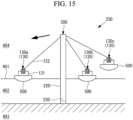
- the winch 130 may be installed to a vessel 500 as illustrated in Fig. 15 or may be installed to the bottom of water as illustrated in Fig. 16 . Further, as illustrated in Fig. 17 , the winch 130 installed to the vessel 500 and the winch 130 installed to the bottom of water may be combined.
- a plurality of winches 130 are installed.
- three winches 130 (a winch 130a, a winch 130b, and a winch 130c) are installed.
- the whole or a part of the construction 200 is cut at the cutting plane 230 set near the base of the construction 200 to tilt the tilting structure 330.
- One winch 130 (for example, the winch 130a) out of the winches 130 tows the tilting structure 330 in a predetermined direction (a direction intended for tilting), and the remaining two winches 130 (for example, the winch 130b and the winch 130c) adjust the tilting speed by making a balance with the towing force of the winch 130a.
- the towing force of the winch 130a serves as a trigger to tilt the tilting structure 330.
- the embodiment tilts the construction 200 by towing the upper part of the construction 200, it is possible to control the tilting speed or the tilting direction by the towing direction or the towing force.
- connection member 141 connecting one construction 200 (first construction 200) and another construction 200 (second construction 200) to each other may be installed, as illustrated in Fig. 18 .
- the connection member 141 is a wire 141, for example.
- tilting the tilting structure 330 including the first construction 200 it is possible to tilt the tilting structure 330 including the second construction 200 in a chain reaction. That is, towing force of the wire 141 generated by tilting the tilting structure 330 can be utilized as a load serving as a trigger to tilt the other tilting structure 330.
- one tilting structure 330 and another tilting structure 330 will support each other by the wire 141, a fall that would otherwise occur immediately after separated from the bottom of water can be prevented.
- the method for tilting a construction (200) is a method for tilting a construction to tilt a bottom-mounted construction extending upward from a ground (401), and the method includes: an installation step of mounting a resistive member (110) to the construction, the resistive member being subjected to fluid force from a fluid surrounding the construction; and a tilting step of tilting the construction to which the resistive member is mounted.
- the method for tilting a construction since the method includes the installation step of mounting, to the construction, the resistive member subjected to fluid force from a fluid surrounding the construction and the tilting step of tilting the construction to which the resistive member is mounted, the tilting speed of the construction can be reduced by fluid force that the resistive member is subjected to when the construction is tilted. This makes it possible to safely tilt the construction. Further, the impact when the construction collides with the water surface or the surface of land can be reduced.
- ground is a term including not only land but also a bottom of water such as a sea bed or a lake bed. That is, the construction targeted in the present aspect may be installed on land or may be installed to a bottom of water such as a sea bed.
- the resistive member is preferably a member that is lightweight but still has a large area of a portion subjected to resistance from a fluid or a member that can be efficiently subjected to resistance from a fluid.
- Examples of the resistive member may be a sail, a board, a vane wheel, or the like.
- the construction is an aquatic construction extending from a bottom of water, and the resistive member is located in surrounding water and/or surrounding air.
- the construction is an aquatic construction extending from a bottom of water, and the resistive member is located in the surrounding water and/or the surrounding air and thus can be subjected to the fluid force from water of the surrounding water and/or air of the surrounding air.
- the method for tilting the construction is a method for tilting a construction to tilt a bottom-mounted construction extending upward from a bottom of water, and the method includes: an installation step of mounting a floating member (120) to the construction, the floating member being subjected to floating force from water; and a tilting step of tilting the construction to which the floating member is mounted.
- the method for tilting the construction of the present aspect since the method includes the installation step of mounting, to the construction, the floating member subjected to floating force from water and the tilting step of tilting the construction to which the floating member is mounted, it is possible to prevent the construction from falling immediately after separated from the bottom of water by using floating force that the floating member is subjected to, and the construction can be made self-supporting as a floating object. Accordingly, the tilting speed can be adjusted when the construction is tilted. This allows the construction to be safely tilted. Further, the impact when the construction collides with the water surface can be reduced.
- the tilting step includes towing an upper part of the construction to tilt the construction.
- the tilting speed or the tilting direction can be controlled by the towing direction or the towing force.
- the construction has a first construction and a second construction installed spaced away from each other
- the method includes a connection step of connecting the first construction and the second construction before the tilting step, and the tilting step including tilting the first construction to tilt the second construction in a chain reaction.
- the construction has the first construction and the second construction installed spaced away from each other
- the method includes the connection step of connecting the first construction and the second construction before the tilting step, and in the tilting step, the first construction is tilted to tilt the second construction in a chain reaction, and thus, by tilting one construction out of a plurality of constructions, it is possible to tilt the remaining construction in a chain reaction.
- first construction and the second construction support each other and thus are prevented from falling immediately after separated from the bottom of water.
- the method for tilting the construction is a method for tilting a construction to tilt a bottom-mounted construction extending upward from a bottom of water, and the method includes: an installation step of mounting a towing member (132) to an upper part of the construction, the towing member being configured to tow the construction; and a tilting step of tilting the construction by towing the construction to which the towing member is mounted.
- the method for tilting the construction includes, before the tilting step, a cutting step of forming a cutting part that divides the construction into a ground side portion of the construction and a portion above the ground side portion of the construction.
- the method for tilting the construction includes, before the tilting step, a cutting step of partially forming a cutting part that divides the construction into a ground side portion of the construction and a portion above the ground side portion of the construction.
- the tilting structure (310) includes a bottom-mounted construction extending upward from a ground; and a resistive member mounted to the construction and subjected to fluid force from a fluid surrounding the construction.
- the tilting structure (320) includes a bottom-mounted construction extending upward from a bottom of water; and a floating member mounted to the construction and subjected to floating force from water.
- the tilting structure (330) includes a bottom-mounted construction extending upward from a ground; and a towing member (132) mounted to an upper part of the construction and configured to tow the construction.
Landscapes
- Engineering & Computer Science (AREA)
- General Engineering & Computer Science (AREA)
- Mechanical Engineering (AREA)
- Civil Engineering (AREA)
- Structural Engineering (AREA)
- Foundations (AREA)
- Working Measures On Existing Buildindgs (AREA)
Abstract
Description
- The present disclosure relates to a method for tilting a construction and a tilting structure.
- When demolishing a construction on land extending perpendicularly, such as a tower type construction, for example, a method of cutting, on the base side, collapsing, and then demolishing the construction is considered as an inexpensive demolishing method that avoids high-place work as much as possible (for example,
Japanese Patent No. 4828314 -
Japanese Patent No. 4828314 - When such a demolishing method is applied to a bottom-mounted aquatic construction, however, (1) waves rise on the water surface when the construction falls and this may be hazardous to vessels or the like nearby, (2) contaminants (debris, dust, oil, or the like of the construction) attached to the construction when the construction is falling and after the construction falls or contaminants included in the construction may be scattered or flow out in water, and this may cause contamination, and (3) the fallen construction may sink into water and may no longer be collected.
- Further, to safely tilt a construction when demolishing a tower type construction without being limited to an aquatic construction, it is preferable to control at least one of the tilting speed and the tilting direction of the construction.
- The present disclosure has been made in view of such circumstances and intends to provide a method for tilting a construction and a tilting structure that can control at least one of the tilting speed and the tilting direction of the construction.
- To solve the above problem, the method for tilting a construction and the tilting structure of the present disclosure employ the following solution.
- That is, a method for tilting a construction according to one aspect of the present disclosure is a method for tilting a construction to tilt a bottom-mounted construction extending upward from a ground, and the method includes: an installation step of mounting a resistive member to the construction, the resistive member being subjected to fluid force from a fluid surrounding the construction; and a tilting step of tilting the construction to which the resistive member is mounted.
- Further, a tilting structure according to one aspect of the present disclosure includes: a bottom-mounted construction extending upward from a ground; and a resistive member mounted to the construction and subjected to fluid force from a fluid surrounding the construction.
- According to the present disclosure, it is possible to control at least one of the tilting speed and the tilting direction of a construction.
-
-
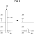
Fig. 1 is a diagram illustrating a view before and after removal of an aquatic construction. -
Fig. 2 is a front view of a tilting structure according to a first embodiment of the present disclosure. -
Fig. 3 is a side view of the tilting structure according to the first embodiment of the present disclosure. -
Fig. 4 is a front view of the tilting structure according to the first embodiment of the present disclosure. -
Fig. 5 is a side view of the tilting structure according to the first embodiment of the present disclosure. -
Fig. 6 is a front view of a tilting structure according to another example of the first embodiment of the present disclosure. -
Fig. 7 is a side view of the tilting structure according to another example of the first embodiment of the present disclosure. -
Fig. 8 is a diagram illustrating a method of cutting a structure. -
Fig. 9 is a diagram illustrating the method of cutting the structure. -
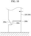
Fig. 10 is a diagram illustrating the method of cutting the structure. -
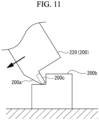
Fig. 11 is a diagram illustrating the method of cutting the structure. -
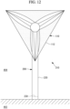
Fig. 12 is a front view of a tilting structure according to a modified example of the first embodiment of the present disclosure. -
Fig. 13 is a front view of a tilting structure according to a second embodiment of the present disclosure. -
Fig. 14 is a front view of the tilting structure according to the second embodiment of the present disclosure. -
Fig. 15 is a front view of a tilting structure according to a third embodiment of the present disclosure. -
Fig. 16 is a front view of the tilting structure according to the third embodiment of the present disclosure. -
Fig. 17 is a front view of the tilting structure according to the third embodiment of the present disclosure. -
Fig. 18 is a front view of a tilting structure according to a modified example of the third embodiment of the present disclosure. - As illustrated in
Fig. 1 , the tilting method and the tilting structure according to each embodiment of the present disclosure are a method and a structure used when aconstruction 200 is demolished. - Note that "demolish" as used herein does not mean an operation to dismantle the
construction 200 itself but means an operation to disconnect theconstruction 200 from aground 401 and put the disconnectedconstruction 200 to be ready to be moved from the installation place. - Further, "
ground 401" is a term including not only land but also a bottom of water such as a sea bed or a lake bed. In each embodiment described below, when the type of theground 401 is not particularly referred to, theground 401 can include land and a bottom of water. - The
construction 200 is a bottom-mounted construction extending perpendicularly upward from the ground 401 (that is, having a longitudinal direction in the perpendicular direction) in a state of being installed on theground 401. - Examples of the
construction 200 may be a weather observation tower, a leg structure of an offshore facility, a lighthouse, a transmission line tower, a wind turbine for power generation, or the like. - The
construction 200 has afoundation 210 and aconstruction body 220. - Note that the boundary between the
foundation 210 and theconstruction body 220 is not required to be a distinct separation in theconstruction 200. - The
foundation 210 extends perpendicularly, and the lower part thereof has been driven in theground 401. - Besides the monopile type as depicted, a jacket type, a tri-pot type, a tri-pile type, or the like may be employed for the
foundation 210, and the specific form of the construction is not limited as long as it is a bottom-mounted type. - The
construction body 220 is provided on the top of thefoundation 210 in the perpendicular direction. - When the
ground 401 is a bottom of water, that is, when theconstruction 200 is an aquatic construction, a portion including the upper end of theconstruction body 220 appears above thewater surface 403. - The
construction body 220 is a portion that exerts the substantial function as theconstruction 200. Since theconstruction body 220 contains devices required for exerting the function thereof, the weight of theconstruction body 220 is often greater than the weight of thefoundation 210. - The method for tilting the
construction 200 and a tilting structure will be specifically described below with examples of a plurality of embodiments. - A method for tilting the construction and a tilting structure according to a first embodiment of the present disclosure will be described with reference to
Fig. 2 to Fig. 12 . - In the method for tilting a construction of the present embodiment, a
tilting structure 310 formed such that aresistive member 110 is mounted to theconstruction 200 is tilted, and thereby theconstruction 200 is tilted. - As illustrated in
Fig. 2 andFig. 3 ,Fig. 4 andFig. 5 , andFig. 6 andFig. 7 , thetilting structure 310 has theconstruction 200 and theresistive member 110. - The
construction 200 is an aquatic construction erected from a bottom of water, for example, and thefoundation 210 and the lower part of theconstruction body 220 are present in a surroundingwater 402. Further, the upper part of theconstruction body 220 is present in a surroundingair 404. - Note that, for example, in a case of a land construction having the
construction 200 erected from the land, the entire part of thefoundation 210 and theconstruction body 220 are present in the surroundingair 404. - The
resistive member 110 is a member mounted to the construction 200 (for example, the side surface of the construction body 220) and subjected to fluid force as a resistance from a fluid surrounding theconstruction 200. - When the
construction 200 is an aquatic construction, the fluid surrounding theconstruction 200 refers to water of the surrounding water 402 (seeFig. 2 andFig. 3 ) or air of the surrounding air 404 (seeFig. 4 andFig. 5 ) or both of the water and air. Further, when theconstruction 200 is a land construction, the fluid surrounding theconstruction 200 refers to air of the surroundingair 404. - The
resistive member 110 is preferably a member that is lightweight but still has a large area of a portion subjected to resistance from a fluid or a member that can be efficiently subjected to resistance from a fluid and may be, for example, a sail, a board, a vane wheel, or the like. - The structure of a specific example when the
resistive member 110 is a sail will be described below. - As illustrated in
Fig. 2 andFig. 3 and alsoFig. 4 andFig. 5 , theresistive member 110 haspoles 111 andsail bodies 112. - Each
pole 111 is a long bar-like component mounted on the side surface of theconstruction body 220 and protruding in the horizontal direction. - For example, each
pole 111 is mounted at each of positions that are symmetrical by 180 degrees with respect to theconstruction body 220. Accordingly, theconstruction 200 will be subjected to fluid force evenly in the horizontal direction (the lateral direction inFig. 2 ) via theresistive member 110. - Each
sail body 112 is a curtain-like component stretched between thepole 111 and theconstruction body 220. Thesail body 112 is a component is subjected to the most part of resistance from a fluid in theresistive member 110. - The
sail body 112 is stretched by being connected to three points of the tip of thepole 111, the base of thepole 111, and the side surface of theconstruction body 220, for example. In such a case, thesail body 112 is substantially triangular. - Note that the form of the
pole 111 and thesail body 112 of theresistive member 110 is not limited to the specific example described above, and may be any form as long as thesail body 112 is stretched so as to be subjected to fluid force from water of the surroundingwater 402 and/or air of the surroundingair 404. - The structure of a specific example when the
resistive member 110 is a vane wheel will be described below. - As illustrated in
Fig. 6 andFig. 7 , theresistive member 110 has vanewheel bodies 116 andducts 117. - Each
vane wheel body 116 is housed inside eachcylindrical duct 117 and is rotatable about the rotary axis Xf extending along the axis Xd of theduct 117. - The
vane wheel body 116 may be driven by a drive unit (not illustrated) such as an electric motor or may be merely installed to be rotatable. - In the case of the former, it is possible to efficiently adjust the tilting speed by controlling the rotational rate of the
vane wheel body 116. In the case of the latter, thevane wheel body 116 will be rotated by fluid force to generate resistance. - Each
duct 117 housing thevane wheel body 116 is fixed and connected to theconstruction body 220 by apole 118 and mounted at each of positions that are symmetrical by 180 degrees with respect to theconstruction body 220, for example. - In the
resistive member 110 configured as described above, for example, theresistive member 110 may be configured to be rotatable and movable with respect to theconstruction 200 so as to be able to change the direction in which the sail or the vane wheel is subjected to fluid force from water of the surroundingwater 402 and/or air of the surroundingair 404. - Further, the
resistive member 110 may be mounted in advance during construction of theconstruction 200 or may be mounted immediately before demolition of theconstruction 200. Further, thepole 111 or thepole 118 may be mounted in advance during construction of theconstruction 200, and thesail body 112 or thevane wheel body 116 and theduct 117 may be mounted immediately before demolition. - In the tilting
structure 310 configured as described above, the whole or a part of theconstruction 200 is cut at a cuttingplane 230 set near the base of theconstruction 200 to tilt the tiltingstructure 310. - At this time, the
resistive member 110 is subjected to fluid force as resistance from water of the surroundingwater 402 and/or air of the surroundingair 404, and thereby the tilting speed of the tiltingstructure 310 is reduced. - Note that, when a sail is employed as the
resistive member 110, it is possible to adjust the tilting speed by increasing or decreasing the area of the surface of thesail body 112 to be subjected to the resistance, for example. - Further, when a vane wheel is employed as the
resistive member 110, it is possible to efficiently adjust the tilting speed by controlling the rotational rate of the vane wheel, for example. - When cutting the
construction 200, it is possible to adjust the tilting direction of the tiltingstructure 310 by undergoing the same steps as those for felling a tree, as illustrated inFig. 8 to Fig. 11 . - Specifically, first, as illustrated in
Fig. 8 andFig. 9 , anotch 200a is formed in the side surface of theconstruction 200. - The
notch 200a is formed in a direction intended to tilt the tiltingstructure 310. - Next, as illustrated in
Fig. 10 , abackcut 200b is formed horizontally toward thenotch 200a from the side surface of theconstruction 200 on the opposite side from thenotch 200a. At this time, ahinge 200c serving as a fulcrum for tilting is left. - Finally, as illustrated in
Fig. 10 andFig. 11 , a load serving as a trigger is applied so that the tiltingstructure 310 is tilted in a direction of closing thenotch 200a. This makes it possible to tilt the tiltingstructure 310 in a desired direction. - Note that a tool to apply a load serving as a trigger may be a winch 130 (a wire 132) as an example that will be described in a third embodiment.
- According to the present embodiment, the following advantageous effects are achieved.
- Since the embodiment includes an installation step of mounting the
resistive member 110 to theconstruction 200 and a tilting step of tilting theconstruction 200 to which theresistive member 110 is mounted (that is, the tilting structure 310), the tilting speed of theconstruction 200 can be reduced by fluid force that theresistive member 110 is subjected to when theconstruction 200 is tilted. - Accordingly, the
construction 200 can be safely tilted. Further, the impact when theconstruction 200 collides with thewater surface 403 or the surface of land can be reduced. - As illustrated in
Fig. 12 , when theconstruction 200 is a wind wheel, for example, sailbodies 112 may be stretched between the blades. - In such a case, the
sail bodies 112 are stretched by being connected to three points, that is, the tip of a blade, the tip of an adjacent blade, and a hub, for example. - A method for tilting a construction and a tilting structure according to a second embodiment of the present disclosure will be described with reference to
Fig. 13 andFig. 14 . - Note that a tilting
structure 320 according to the present embodiment differs from the tiltingstructure 310 according to the first embodiment in that the tiltingstructure 320 does not have theresistive member 110 but has a floatingmember 120. Thus, the same configurations are labeled with the same reference, and the description thereof will be omitted. - The method for tilting a construction of the present embodiment tilts the tilting
structure 320 formed such that the floatingmember 120 is mounted to theconstruction 200 and thereby tilts theconstruction 200. - As illustrated in
Fig. 13 andFig. 14 , the tiltingstructure 320 has theconstruction 200 and the floatingmember 120. - Note that, in the case of the present embodiment, the
construction 200 is an aquatic construction erected from a bottom of water such as a sea bed. - The floating
member 120 is a member mounted to the construction 200 (for example, the side surface of the construction body 220) and subjected to floating force from water surrounding theconstruction 200. - The floating force obtained by the floating
member 120 supports theconstruction 200 that is separate from the bottom of water. In other words, the specification of the floatingmember 120 is designed so that floating force that supports theconstruction 200 that is separate from the bottom of water is generated. - The floating
member 120 may be provided over the whole circumference of theconstruction 200 or may be provided to a part of the circumference. - The floating
member 120 is formed of a bag-like object made of a material such as nylon, rubber, or the like with a gas being filled inside the object, for example. - The floating
member 120 may be mounted during construction of theconstruction 200 or may be mounted immediately before demolition of theconstruction 200. - In the tilting
structure 320 configured as described above, the whole or a part of theconstruction 200 is cut at the cuttingplane 230 set near the base of theconstruction 200. - At this time, the floating
member 120 is subjected to floating force from the water, and this can prevent thetilting structure 310 from falling or being tilted due to its own weight. That is, even after theconstruction 200 is separated from the bottom of water, theconstruction 200 can be made self-supporting as a floating object. - Once the
construction 200 is separated from the bottom of water, the tiltingstructure 320 is tilted by a predetermined tool. At this time, since theconstruction 200 relies on the floatingmember 120 to maintain the self-supporting state, the tilting speed of theconstruction 200 can be adjusted when theconstruction 200 is tilted. - Note that the tool for tilting the tilting
structure 320 may be the winch 130 (the wire 132) as an example that will be described in the third embodiment. - According to the present embodiment, the following advantageous effects are achieved.
- Since the embodiment includes an installation step of mounting the floating
member 120 to theconstruction 200 and a tilting step of tilting theconstruction 200 to which the floatingmember 120 is mounted (that is, the tilting structure 320), theconstruction 200 can be made self-supporting as a floating object even after theconstruction 200 is separated from the bottom of water. - Accordingly, when the
construction 200 is tilted, the tilting speed of theconstruction 200 can be adjusted, and theconstruction 200 can be safely tilted. Further, the impact when theconstruction 200 collides with thewater surface 403 can be reduced. - A method for tilting a construction and a tilting structure according to a third embodiment of the present disclosure will be described with reference to
Fig. 15 to Fig. 17 . - Note that a tilting
structure 330 according to the present embodiment differs from the tiltingstructure 310 according to the first embodiment in that the tiltingstructure 330 does not have theresistive member 110 but has towingmembers 132. Thus, the same configurations are labeled with the same reference, and the description thereof will be omitted. - The method for tilting a construction of the present embodiment is a method for tilting the tilting
structure 330 having the towingmembers 132 connected to theconstruction 200. In the method for tilting a construction of the present embodiment, the towingmembers 132 are towed, and thereby theconstruction 200 is tilted. - As illustrated in
Fig. 15 , the tiltingstructure 330 has theconstruction 200 and the towingmembers 132. - The towing
members 132 arewires 132 ofwinches 130, for example. - Each of the
winches 130 has awinch body 131 in addition to thewire 132. - The
winch body 131 is a portion to unwind/wind up thewire 132 therefrom/thereon. - One end of the
wire 132 is connected to thewinch body 131, and the other end is connected to the upper part of the construction 200 (specifically, the upper part of the construction body 220). - The
winch 130 may be installed to avessel 500 as illustrated inFig. 15 or may be installed to the bottom of water as illustrated inFig. 16 . Further, as illustrated inFig. 17 , thewinch 130 installed to thevessel 500 and thewinch 130 installed to the bottom of water may be combined. - In any case, a plurality of
winches 130 are installed. In the case ofFig. 15 , three winches 130 (awinch 130a, awinch 130b, and awinch 130c) are installed. - It is preferable to mount the
wire 132 of thewinch 130 immediately before demolishing theconstruction 200. - In the tilting
structure 330 configured as described above, the whole or a part of theconstruction 200 is cut at the cuttingplane 230 set near the base of theconstruction 200 to tilt the tiltingstructure 330. - One winch 130 (for example, the
winch 130a) out of thewinches 130 tows the tiltingstructure 330 in a predetermined direction (a direction intended for tilting), and the remaining two winches 130 (for example, thewinch 130b and thewinch 130c) adjust the tilting speed by making a balance with the towing force of thewinch 130a. - This makes it possible to adjust the tilting speed while tilting the tilting
structure 330 in a desired direction. - Note that, when cutting the
construction 200, the same steps as those for felling a tree as illustrated inFig. 8 to Fig. 11 may be applied. In such a case, the towing force of thewinch 130a serves as a trigger to tilt the tiltingstructure 330. - According to the present embodiment, the following advantageous effects are achieved.
- Since the embodiment tilts the
construction 200 by towing the upper part of theconstruction 200, it is possible to control the tilting speed or the tilting direction by the towing direction or the towing force. - For example, instead of
respective wires 132 of thewinch 130b and thewinch 130c illustrated inFig. 15 , aconnection member 141 connecting one construction 200 (first construction 200) and another construction 200 (second construction 200) to each other may be installed, as illustrated inFig. 18 . Theconnection member 141 is awire 141, for example. - Accordingly, by tilting the tilting
structure 330 including thefirst construction 200, it is possible to tilt the tiltingstructure 330 including thesecond construction 200 in a chain reaction. That is, towing force of thewire 141 generated by tilting the tiltingstructure 330 can be utilized as a load serving as a trigger to tilt theother tilting structure 330. - Further, since one
tilting structure 330 and another tiltingstructure 330 will support each other by thewire 141, a fall that would otherwise occur immediately after separated from the bottom of water can be prevented. - The method for tilting a construction and the tilting structure according to each embodiment as described above are understood as follows, for example.
- That is, the method for tilting a construction (200) according to one aspect of the present disclosure is a method for tilting a construction to tilt a bottom-mounted construction extending upward from a ground (401), and the method includes: an installation step of mounting a resistive member (110) to the construction, the resistive member being subjected to fluid force from a fluid surrounding the construction; and a tilting step of tilting the construction to which the resistive member is mounted.
- According to the method for tilting a construction according to the present aspect, since the method includes the installation step of mounting, to the construction, the resistive member subjected to fluid force from a fluid surrounding the construction and the tilting step of tilting the construction to which the resistive member is mounted, the tilting speed of the construction can be reduced by fluid force that the resistive member is subjected to when the construction is tilted. This makes it possible to safely tilt the construction. Further, the impact when the construction collides with the water surface or the surface of land can be reduced.
- Note that the "ground" as used herein is a term including not only land but also a bottom of water such as a sea bed or a lake bed. That is, the construction targeted in the present aspect may be installed on land or may be installed to a bottom of water such as a sea bed.
- The resistive member is preferably a member that is lightweight but still has a large area of a portion subjected to resistance from a fluid or a member that can be efficiently subjected to resistance from a fluid. Examples of the resistive member may be a sail, a board, a vane wheel, or the like.
- Further, in the method for tilting the construction according to one aspect of the present disclosure, the construction is an aquatic construction extending from a bottom of water, and the resistive member is located in surrounding water and/or surrounding air.
- According to the method for tilting the construction of the present aspect, the construction is an aquatic construction extending from a bottom of water, and the resistive member is located in the surrounding water and/or the surrounding air and thus can be subjected to the fluid force from water of the surrounding water and/or air of the surrounding air.
- Further, the method for tilting the construction according to one aspect of the present disclosure is a method for tilting a construction to tilt a bottom-mounted construction extending upward from a bottom of water, and the method includes: an installation step of mounting a floating member (120) to the construction, the floating member being subjected to floating force from water; and a tilting step of tilting the construction to which the floating member is mounted.
- According to the method for tilting the construction of the present aspect, since the method includes the installation step of mounting, to the construction, the floating member subjected to floating force from water and the tilting step of tilting the construction to which the floating member is mounted, it is possible to prevent the construction from falling immediately after separated from the bottom of water by using floating force that the floating member is subjected to, and the construction can be made self-supporting as a floating object. Accordingly, the tilting speed can be adjusted when the construction is tilted. This allows the construction to be safely tilted. Further, the impact when the construction collides with the water surface can be reduced.
- Further, in the method for tilting the construction according to one aspect of the present disclosure, the tilting step includes towing an upper part of the construction to tilt the construction.
- According to the method for tilting the construction of the present aspect, since the construction is tilted by towing the upper part of the construction in the tilting step, the tilting speed or the tilting direction can be controlled by the towing direction or the towing force.
- Note that it is preferable to perform towing from a plurality of directions.
- Further, in the method for tilting the construction according to one aspect of the present disclosure, the construction has a first construction and a second construction installed spaced away from each other, the method includes a connection step of connecting the first construction and the second construction before the tilting step, and the tilting step including tilting the first construction to tilt the second construction in a chain reaction.
- According to the method for tilting the construction of the present aspect, the construction has the first construction and the second construction installed spaced away from each other, the method includes the connection step of connecting the first construction and the second construction before the tilting step, and in the tilting step, the first construction is tilted to tilt the second construction in a chain reaction, and thus, by tilting one construction out of a plurality of constructions, it is possible to tilt the remaining construction in a chain reaction.
- Further, the first construction and the second construction support each other and thus are prevented from falling immediately after separated from the bottom of water.
- Further, the method for tilting the construction according to one aspect of the present disclosure is a method for tilting a construction to tilt a bottom-mounted construction extending upward from a bottom of water, and the method includes: an installation step of mounting a towing member (132) to an upper part of the construction, the towing member being configured to tow the construction; and a tilting step of tilting the construction by towing the construction to which the towing member is mounted.
- Further, the method for tilting the construction according to one aspect of the present disclosure includes, before the tilting step, a cutting step of forming a cutting part that divides the construction into a ground side portion of the construction and a portion above the ground side portion of the construction.
- Further, the method for tilting the construction according to one aspect of the present disclosure includes, before the tilting step, a cutting step of partially forming a cutting part that divides the construction into a ground side portion of the construction and a portion above the ground side portion of the construction.
- Further, the tilting structure (310) according to one aspect of the present disclosure includes a bottom-mounted construction extending upward from a ground; and a resistive member mounted to the construction and subjected to fluid force from a fluid surrounding the construction.
- Further, the tilting structure (320) according to one aspect of the present disclosure includes a bottom-mounted construction extending upward from a bottom of water; and a floating member mounted to the construction and subjected to floating force from water.
- Further, the tilting structure (330) according to one aspect of the present disclosure includes a bottom-mounted construction extending upward from a ground; and a towing member (132) mounted to an upper part of the construction and configured to tow the construction.
-
- 110
- resistive member
- 111
- pole
- 112
- sail body
- 116
- vane wheel body
- 117
- duct
- 118
- pole
- 120
- floating member
- 130
- winch
- 131
- winch body
- 132
- wire (towing member)
- 141
- wire (connection member)
- 200
- construction
- 200a
- notch
- 200b
- backcut
- 200c
- hinge
- 210
- foundation
- 220
- construction body
- 230
- cutting plane
- 310, 320, 330
- tilting structure
- 401
- ground
- 402
- surrounding water
- 403
- water surface
- 404
- surrounding air
- 500
- vessel
Claims (11)
- A method for tilting a construction to tilt a bottom-mounted construction extending upward from a ground, the method comprising:an installation step of mounting a resistive member to the construction, the resistive member being subjected to fluid force from a fluid surrounding the construction; anda tilting step of tilting the construction to which the resistive member is mounted.
- The method for tilting the construction according to claim 1,wherein the construction is an aquatic construction extending from a bottom of water, andwherein the resistive member is located in surrounding water and/or surrounding air.
- A method for tilting a construction to tilt a bottom-mounted construction extending upward from a bottom of water, the method comprising:an installation step of mounting a floating member to the construction, the floating member being subjected to floating force from water; anda tilting step of tilting the construction to which the floating member is mounted.
- The method for tilting the construction according to any one of claims 1 to 3,
wherein the tilting step includes towing an upper part of the construction to tilt the construction. - The method for tilting the construction according to any one of claims 1 to 4,
wherein the construction has a first construction and a second construction installed spaced away from each other,
the method further comprising:a connection step of connecting the first construction and the second construction before the tilting step,wherein the tilting step includes tilting the first construction to tilt the second construction in a chain reaction. - A method for tilting a construction to tilt a bottom-mounted construction extending upward from a bottom of water, the method comprising:an installation step of mounting a towing member to an upper part of the construction, the towing member being configured to tow the construction; anda tilting step of tilting the construction by towing the construction to which the towing member is mounted.
- The method for tilting the construction according to any one of claims 1 to 6 further comprising, before the tilting step, a cutting step of forming a cutting part that divides the construction into a ground side portion of the construction and a portion above the ground side portion of the construction.
- The method for tilting the construction according to any one of claims 1 to 6 further comprising, before the tilting step, a cutting step of partially forming a cutting part that divides the construction into a ground side portion of the construction and a portion above the ground side portion of the construction.
- A tilting structure comprising:a bottom-mounted construction extending upward from a ground; anda resistive member mounted to the construction and subjected to fluid force from a fluid surrounding the construction.
- A tilting structure comprising:a bottom-mounted construction extending upward from a bottom of water; anda floating member mounted to the construction and subjected to floating force from water.
- A tilting structure comprising:a bottom-mounted construction extending upward from a ground; anda towing member mounted to an upper part of the construction and configured to tow the construction.
Applications Claiming Priority (1)
| Application Number | Priority Date | Filing Date | Title |
|---|---|---|---|
| JP2022012955A JP7798592B2 (en) | 2022-01-31 | 2022-01-31 | Method for tilting a structure and tilting structure |
Publications (2)
| Publication Number | Publication Date |
|---|---|
| EP4219837A1 true EP4219837A1 (en) | 2023-08-02 |
| EP4219837B1 EP4219837B1 (en) | 2025-12-10 |
Family
ID=84982608
Family Applications (1)
| Application Number | Title | Priority Date | Filing Date |
|---|---|---|---|
| EP23152147.7A Active EP4219837B1 (en) | 2022-01-31 | 2023-01-18 | Method for tilting construction and tilting structure |
Country Status (2)
| Country | Link |
|---|---|
| EP (1) | EP4219837B1 (en) |
| JP (1) | JP7798592B2 (en) |
Families Citing this family (1)
| Publication number | Priority date | Publication date | Assignee | Title |
|---|---|---|---|---|
| WO2024157454A1 (en) * | 2023-01-27 | 2024-08-02 | 三菱重工業株式会社 | Method for dismantling construction structure |
Citations (4)
| Publication number | Priority date | Publication date | Assignee | Title |
|---|---|---|---|---|
| US6269761B1 (en) * | 1996-05-16 | 2001-08-07 | Controlled Variable Buoyancy Systems Limited | Buoyancy device |
| US6550411B1 (en) * | 1999-06-14 | 2003-04-22 | Excalibur Engineering B.V. | Method for removing a jacket of a drilling or production rig and vessel provided with a device therefor |
| JP4828314B2 (en) | 2006-06-09 | 2011-11-30 | ベステラ株式会社 | Method of defeating steel tower supported chimney structure |
| US20150167646A1 (en) * | 2012-07-26 | 2015-06-18 | Vestas Wind Systems As | Tilting wind turbine |
Family Cites Families (3)
| Publication number | Priority date | Publication date | Assignee | Title |
|---|---|---|---|---|
| WO2016092609A1 (en) | 2014-12-08 | 2016-06-16 | ベステラ株式会社 | Method for bringing down power generation wind turbine |
| DE102017124412A1 (en) | 2017-10-19 | 2019-04-25 | Innogy Se | Soft-Soft foundation for offshore structures |
| EP3674199A1 (en) * | 2018-12-24 | 2020-07-01 | UK Decom Limited | Decommissioning of offshore structures |
-
2022
- 2022-01-31 JP JP2022012955A patent/JP7798592B2/en active Active
-
2023
- 2023-01-18 EP EP23152147.7A patent/EP4219837B1/en active Active
Patent Citations (4)
| Publication number | Priority date | Publication date | Assignee | Title |
|---|---|---|---|---|
| US6269761B1 (en) * | 1996-05-16 | 2001-08-07 | Controlled Variable Buoyancy Systems Limited | Buoyancy device |
| US6550411B1 (en) * | 1999-06-14 | 2003-04-22 | Excalibur Engineering B.V. | Method for removing a jacket of a drilling or production rig and vessel provided with a device therefor |
| JP4828314B2 (en) | 2006-06-09 | 2011-11-30 | ベステラ株式会社 | Method of defeating steel tower supported chimney structure |
| US20150167646A1 (en) * | 2012-07-26 | 2015-06-18 | Vestas Wind Systems As | Tilting wind turbine |
Also Published As
| Publication number | Publication date |
|---|---|
| EP4219837B1 (en) | 2025-12-10 |
| JP7798592B2 (en) | 2026-01-14 |
| JP2023111211A (en) | 2023-08-10 |
Similar Documents
| Publication | Publication Date | Title |
|---|---|---|
| JP7008705B2 (en) | Offshore vessels, wave-induced motion-induced motion cranes for use in vessels, and cargo hauling methods. | |
| JP4335214B2 (en) | Rotor blade mounting method and wind turbine rotor blade | |
| CN110719886B (en) | Motion compensated crane for use on a marine vessel | |
| JP5760133B2 (en) | Column-stabilized offshore platform with water entrapment plate and asymmetric mooring system for offshore wind turbine support | |
| WO2013051167A1 (en) | Blade attaching and detaching device and method for wind turbine generator | |
| JP7566885B2 (en) | Method for lifting an object from a ship deck | |
| EP4219837B1 (en) | Method for tilting construction and tilting structure | |
| GB2372783A (en) | Turbine means to generate energy from wind and water on a sailing vessel | |
| CA2995076C (en) | Pile removal system | |
| US9739267B2 (en) | Wind turbine on a floating support stabilized by a raised anchoring system | |
| CN110985308A (en) | Offshore foundation structure and offshore wind turbine system | |
| EP1346154A1 (en) | Mast construction and erection method for offshore installation | |
| JP2008308328A (en) | Mobile crane | |
| JP7753090B2 (en) | Disassembly method | |
| EP4166722B1 (en) | Method for disassembling offshore structure | |
| JP2022183904A (en) | Method for assembling water wind power generation facility and floating structure | |
| JP2023124020A (en) | Tension mooring floating body, floating structure for mooring preparation, detachable column, offshore wind power generation equipment, and tension mooring method for tension mooring floating body | |
| AU2020206885B2 (en) | Excavator | |
| JP3240432U (en) | Typhoon force weakening and suppression device | |
| US6766980B1 (en) | Prop wash deflector | |
| KR100591855B1 (en) | Submersible Hydraulic Wire Cutting Machine | |
| WO2002048482A1 (en) | Apparatus for demolition at great height with means for controlling the rotation in a horizontal plane | |
| CA2438041A1 (en) | Apparatus for production of energy from currents in bodies of water, a foundation, and a method for the installation of the apparatus | |
| CN116857125B (en) | Wind driven generator blade posture adjusting device and method | |
| EP4636199A1 (en) | Method for dismantling construction structure |
Legal Events
| Date | Code | Title | Description |
|---|---|---|---|
| PUAI | Public reference made under article 153(3) epc to a published international application that has entered the european phase |
Free format text: ORIGINAL CODE: 0009012 |
|
| STAA | Information on the status of an ep patent application or granted ep patent |
Free format text: STATUS: THE APPLICATION HAS BEEN PUBLISHED |
|
| AK | Designated contracting states |
Kind code of ref document: A1 Designated state(s): AL AT BE BG CH CY CZ DE DK EE ES FI FR GB GR HR HU IE IS IT LI LT LU LV MC ME MK MT NL NO PL PT RO RS SE SI SK SM TR |
|
| STAA | Information on the status of an ep patent application or granted ep patent |
Free format text: STATUS: REQUEST FOR EXAMINATION WAS MADE |
|
| 17P | Request for examination filed |
Effective date: 20240131 |
|
| RBV | Designated contracting states (corrected) |
Designated state(s): AL AT BE BG CH CY CZ DE DK EE ES FI FR GB GR HR HU IE IS IT LI LT LU LV MC ME MK MT NL NO PL PT RO RS SE SI SK SM TR |
|
| GRAP | Despatch of communication of intention to grant a patent |
Free format text: ORIGINAL CODE: EPIDOSNIGR1 |
|
| STAA | Information on the status of an ep patent application or granted ep patent |
Free format text: STATUS: GRANT OF PATENT IS INTENDED |
|
| RIC1 | Information provided on ipc code assigned before grant |
Ipc: E02B 17/02 20060101AFI20250625BHEP Ipc: B23D 57/00 20060101ALI20250625BHEP Ipc: E02B 17/04 20060101ALI20250625BHEP Ipc: E02B 17/00 20060101ALN20250625BHEP |
|
| INTG | Intention to grant announced |
Effective date: 20250709 |
|
| GRAS | Grant fee paid |
Free format text: ORIGINAL CODE: EPIDOSNIGR3 |
|
| GRAA | (expected) grant |
Free format text: ORIGINAL CODE: 0009210 |
|
| STAA | Information on the status of an ep patent application or granted ep patent |
Free format text: STATUS: THE PATENT HAS BEEN GRANTED |
|
| AK | Designated contracting states |
Kind code of ref document: B1 Designated state(s): AL AT BE BG CH CY CZ DE DK EE ES FI FR GB GR HR HU IE IS IT LI LT LU LV MC ME MK MT NL NO PL PT RO RS SE SI SK SM TR |
|
| REG | Reference to a national code |
Ref country code: CH Ref legal event code: F10 Free format text: ST27 STATUS EVENT CODE: U-0-0-F10-F00 (AS PROVIDED BY THE NATIONAL OFFICE) Effective date: 20251210 Ref country code: GB Ref legal event code: FG4D |
|
| REG | Reference to a national code |
Ref country code: DE Ref legal event code: R096 Ref document number: 602023009399 Country of ref document: DE |
|
| REG | Reference to a national code |
Ref country code: IE Ref legal event code: FG4D |
|
| PG25 | Lapsed in a contracting state [announced via postgrant information from national office to epo] |
Ref country code: ES Free format text: LAPSE BECAUSE OF FAILURE TO SUBMIT A TRANSLATION OF THE DESCRIPTION OR TO PAY THE FEE WITHIN THE PRESCRIBED TIME-LIMIT Effective date: 20251210 |
|
| REG | Reference to a national code |
Ref country code: LT Ref legal event code: MG9D |
|
| PG25 | Lapsed in a contracting state [announced via postgrant information from national office to epo] |
Ref country code: NO Free format text: LAPSE BECAUSE OF FAILURE TO SUBMIT A TRANSLATION OF THE DESCRIPTION OR TO PAY THE FEE WITHIN THE PRESCRIBED TIME-LIMIT Effective date: 20260310 |
|
| PGFP | Annual fee paid to national office [announced via postgrant information from national office to epo] |
Ref country code: DE Payment date: 20260127 Year of fee payment: 4 |
|
| PG25 | Lapsed in a contracting state [announced via postgrant information from national office to epo] |
Ref country code: FI Free format text: LAPSE BECAUSE OF FAILURE TO SUBMIT A TRANSLATION OF THE DESCRIPTION OR TO PAY THE FEE WITHIN THE PRESCRIBED TIME-LIMIT Effective date: 20251210 Ref country code: HR Free format text: LAPSE BECAUSE OF FAILURE TO SUBMIT A TRANSLATION OF THE DESCRIPTION OR TO PAY THE FEE WITHIN THE PRESCRIBED TIME-LIMIT Effective date: 20251210 |
|
| PGFP | Annual fee paid to national office [announced via postgrant information from national office to epo] |
Ref country code: AT Payment date: 20260301 Year of fee payment: 4 |
|
| REG | Reference to a national code |
Ref country code: NL Ref legal event code: MP Effective date: 20251210 |
|
| PG25 | Lapsed in a contracting state [announced via postgrant information from national office to epo] |
Ref country code: RS Free format text: LAPSE BECAUSE OF FAILURE TO SUBMIT A TRANSLATION OF THE DESCRIPTION OR TO PAY THE FEE WITHIN THE PRESCRIBED TIME-LIMIT Effective date: 20260310 |
|
| PG25 | Lapsed in a contracting state [announced via postgrant information from national office to epo] |
Ref country code: LV Free format text: LAPSE BECAUSE OF FAILURE TO SUBMIT A TRANSLATION OF THE DESCRIPTION OR TO PAY THE FEE WITHIN THE PRESCRIBED TIME-LIMIT Effective date: 20251210 |
|
| PG25 | Lapsed in a contracting state [announced via postgrant information from national office to epo] |
Ref country code: BG Free format text: LAPSE BECAUSE OF FAILURE TO SUBMIT A TRANSLATION OF THE DESCRIPTION OR TO PAY THE FEE WITHIN THE PRESCRIBED TIME-LIMIT Effective date: 20251210 |