EP4219317A1 - Fluid module - Google Patents
Fluid module Download PDFInfo
- Publication number
- EP4219317A1 EP4219317A1 EP23154526.0A EP23154526A EP4219317A1 EP 4219317 A1 EP4219317 A1 EP 4219317A1 EP 23154526 A EP23154526 A EP 23154526A EP 4219317 A1 EP4219317 A1 EP 4219317A1
- Authority
- EP
- European Patent Office
- Prior art keywords
- fluid
- coupling
- module
- manifold
- inlet
- Prior art date
- Legal status (The legal status is an assumption and is not a legal conclusion. Google has not performed a legal analysis and makes no representation as to the accuracy of the status listed.)
- Pending
Links
Images





Classifications
-
- F—MECHANICAL ENGINEERING; LIGHTING; HEATING; WEAPONS; BLASTING
- F15—FLUID-PRESSURE ACTUATORS; HYDRAULICS OR PNEUMATICS IN GENERAL
- F15B—SYSTEMS ACTING BY MEANS OF FLUIDS IN GENERAL; FLUID-PRESSURE ACTUATORS, e.g. SERVOMOTORS; DETAILS OF FLUID-PRESSURE SYSTEMS, NOT OTHERWISE PROVIDED FOR
- F15B21/00—Common features of fluid actuator systems; Fluid-pressure actuator systems or details thereof, not covered by any other group of this subclass
- F15B21/04—Special measures taken in connection with the properties of the fluid
- F15B21/041—Removal or measurement of solid or liquid contamination, e.g. filtering
-
- B—PERFORMING OPERATIONS; TRANSPORTING
- B01—PHYSICAL OR CHEMICAL PROCESSES OR APPARATUS IN GENERAL
- B01D—SEPARATION
- B01D35/00—Filtering devices having features not specifically covered by groups B01D24/00 - B01D33/00, or for applications not specifically covered by groups B01D24/00 - B01D33/00; Auxiliary devices for filtration; Filter housing constructions
- B01D35/02—Filters adapted for location in special places, e.g. pipe-lines, pumps, stop-cocks
-
- B—PERFORMING OPERATIONS; TRANSPORTING
- B01—PHYSICAL OR CHEMICAL PROCESSES OR APPARATUS IN GENERAL
- B01D—SEPARATION
- B01D37/00—Processes of filtration
- B01D37/04—Controlling the filtration
- B01D37/046—Controlling the filtration by pressure measuring
-
- B—PERFORMING OPERATIONS; TRANSPORTING
- B64—AIRCRAFT; AVIATION; COSMONAUTICS
- B64C—AEROPLANES; HELICOPTERS
- B64C13/00—Control systems or transmitting systems for actuating flying-control surfaces, lift-increasing flaps, air brakes, or spoilers
- B64C13/24—Transmitting means
- B64C13/26—Transmitting means without power amplification or where power amplification is irrelevant
- B64C13/36—Transmitting means without power amplification or where power amplification is irrelevant fluid
-
- B—PERFORMING OPERATIONS; TRANSPORTING
- B64—AIRCRAFT; AVIATION; COSMONAUTICS
- B64D—EQUIPMENT FOR FITTING IN OR TO AIRCRAFT; FLIGHT SUITS; PARACHUTES; ARRANGEMENT OR MOUNTING OF POWER PLANTS OR PROPULSION TRANSMISSIONS IN AIRCRAFT
- B64D41/00—Power installations for auxiliary purposes
-
- B—PERFORMING OPERATIONS; TRANSPORTING
- B64—AIRCRAFT; AVIATION; COSMONAUTICS
- B64F—GROUND OR AIRCRAFT-CARRIER-DECK INSTALLATIONS SPECIALLY ADAPTED FOR USE IN CONNECTION WITH AIRCRAFT; DESIGNING, MANUFACTURING, ASSEMBLING, CLEANING, MAINTAINING OR REPAIRING AIRCRAFT, NOT OTHERWISE PROVIDED FOR; HANDLING, TRANSPORTING, TESTING OR INSPECTING AIRCRAFT COMPONENTS, NOT OTHERWISE PROVIDED FOR
- B64F5/00—Designing, manufacturing, assembling, cleaning, maintaining or repairing aircraft, not otherwise provided for; Handling, transporting, testing or inspecting aircraft components, not otherwise provided for
- B64F5/40—Maintaining or repairing aircraft
-
- B—PERFORMING OPERATIONS; TRANSPORTING
- B01—PHYSICAL OR CHEMICAL PROCESSES OR APPARATUS IN GENERAL
- B01D—SEPARATION
- B01D2201/00—Details relating to filtering apparatus
- B01D2201/30—Filter housing constructions
- B01D2201/301—Details of removable closures, lids, caps, filter heads
- B01D2201/302—Details of removable closures, lids, caps, filter heads having inlet or outlet ports
- B01D2201/303—Details of removable closures, lids, caps, filter heads having inlet or outlet ports not arranged concentrically
-
- B—PERFORMING OPERATIONS; TRANSPORTING
- B64—AIRCRAFT; AVIATION; COSMONAUTICS
- B64F—GROUND OR AIRCRAFT-CARRIER-DECK INSTALLATIONS SPECIALLY ADAPTED FOR USE IN CONNECTION WITH AIRCRAFT; DESIGNING, MANUFACTURING, ASSEMBLING, CLEANING, MAINTAINING OR REPAIRING AIRCRAFT, NOT OTHERWISE PROVIDED FOR; HANDLING, TRANSPORTING, TESTING OR INSPECTING AIRCRAFT COMPONENTS, NOT OTHERWISE PROVIDED FOR
- B64F1/00—Ground or aircraft-carrier-deck installations
- B64F1/36—Other airport installations
-
- F—MECHANICAL ENGINEERING; LIGHTING; HEATING; WEAPONS; BLASTING
- F15—FLUID-PRESSURE ACTUATORS; HYDRAULICS OR PNEUMATICS IN GENERAL
- F15B—SYSTEMS ACTING BY MEANS OF FLUIDS IN GENERAL; FLUID-PRESSURE ACTUATORS, e.g. SERVOMOTORS; DETAILS OF FLUID-PRESSURE SYSTEMS, NOT OTHERWISE PROVIDED FOR
- F15B1/00—Installations or systems with accumulators; Supply reservoir or sump assemblies
- F15B1/26—Supply reservoir or sump assemblies
-
- F—MECHANICAL ENGINEERING; LIGHTING; HEATING; WEAPONS; BLASTING
- F15—FLUID-PRESSURE ACTUATORS; HYDRAULICS OR PNEUMATICS IN GENERAL
- F15B—SYSTEMS ACTING BY MEANS OF FLUIDS IN GENERAL; FLUID-PRESSURE ACTUATORS, e.g. SERVOMOTORS; DETAILS OF FLUID-PRESSURE SYSTEMS, NOT OTHERWISE PROVIDED FOR
- F15B13/00—Details of servomotor systems ; Valves for servomotor systems
- F15B13/02—Fluid distribution or supply devices characterised by their adaptation to the control of servomotors
- F15B13/06—Fluid distribution or supply devices characterised by their adaptation to the control of servomotors for use with two or more servomotors
- F15B13/08—Assemblies of units, each for the control of a single servomotor only
- F15B13/0803—Modular units
- F15B13/0807—Manifolds
- F15B13/0814—Monoblock manifolds
-
- F—MECHANICAL ENGINEERING; LIGHTING; HEATING; WEAPONS; BLASTING
- F15—FLUID-PRESSURE ACTUATORS; HYDRAULICS OR PNEUMATICS IN GENERAL
- F15B—SYSTEMS ACTING BY MEANS OF FLUIDS IN GENERAL; FLUID-PRESSURE ACTUATORS, e.g. SERVOMOTORS; DETAILS OF FLUID-PRESSURE SYSTEMS, NOT OTHERWISE PROVIDED FOR
- F15B13/00—Details of servomotor systems ; Valves for servomotor systems
- F15B13/02—Fluid distribution or supply devices characterised by their adaptation to the control of servomotors
- F15B13/06—Fluid distribution or supply devices characterised by their adaptation to the control of servomotors for use with two or more servomotors
- F15B13/08—Assemblies of units, each for the control of a single servomotor only
- F15B13/0803—Modular units
- F15B13/0878—Assembly of modular units
- F15B13/0885—Assembly of modular units using valves combined with other components
- F15B13/0892—Valves combined with fluid components
-
- F—MECHANICAL ENGINEERING; LIGHTING; HEATING; WEAPONS; BLASTING
- F15—FLUID-PRESSURE ACTUATORS; HYDRAULICS OR PNEUMATICS IN GENERAL
- F15B—SYSTEMS ACTING BY MEANS OF FLUIDS IN GENERAL; FLUID-PRESSURE ACTUATORS, e.g. SERVOMOTORS; DETAILS OF FLUID-PRESSURE SYSTEMS, NOT OTHERWISE PROVIDED FOR
- F15B19/00—Testing; Calibrating; Fault detection or monitoring; Simulation or modelling of fluid-pressure systems or apparatus not otherwise provided for
- F15B19/005—Fault detection or monitoring
-
- F—MECHANICAL ENGINEERING; LIGHTING; HEATING; WEAPONS; BLASTING
- F15—FLUID-PRESSURE ACTUATORS; HYDRAULICS OR PNEUMATICS IN GENERAL
- F15B—SYSTEMS ACTING BY MEANS OF FLUIDS IN GENERAL; FLUID-PRESSURE ACTUATORS, e.g. SERVOMOTORS; DETAILS OF FLUID-PRESSURE SYSTEMS, NOT OTHERWISE PROVIDED FOR
- F15B2211/00—Circuits for servomotor systems
- F15B2211/60—Circuit components or control therefor
- F15B2211/615—Filtering means
-
- F—MECHANICAL ENGINEERING; LIGHTING; HEATING; WEAPONS; BLASTING
- F15—FLUID-PRESSURE ACTUATORS; HYDRAULICS OR PNEUMATICS IN GENERAL
- F15B—SYSTEMS ACTING BY MEANS OF FLUIDS IN GENERAL; FLUID-PRESSURE ACTUATORS, e.g. SERVOMOTORS; DETAILS OF FLUID-PRESSURE SYSTEMS, NOT OTHERWISE PROVIDED FOR
- F15B2211/00—Circuits for servomotor systems
- F15B2211/60—Circuit components or control therefor
- F15B2211/63—Electronic controllers
- F15B2211/6303—Electronic controllers using input signals
- F15B2211/6306—Electronic controllers using input signals representing a pressure
-
- F—MECHANICAL ENGINEERING; LIGHTING; HEATING; WEAPONS; BLASTING
- F15—FLUID-PRESSURE ACTUATORS; HYDRAULICS OR PNEUMATICS IN GENERAL
- F15B—SYSTEMS ACTING BY MEANS OF FLUIDS IN GENERAL; FLUID-PRESSURE ACTUATORS, e.g. SERVOMOTORS; DETAILS OF FLUID-PRESSURE SYSTEMS, NOT OTHERWISE PROVIDED FOR
- F15B2211/00—Circuits for servomotor systems
- F15B2211/80—Other types of control related to particular problems or conditions
- F15B2211/87—Detection of failures
Definitions
- the present disclosure generally relates to fluid modules, including fluid modules that may be utilized in connection with aircraft.
- a fluid module may comprise a manifold including a filter port, a first inlet in fluid communication with the filter port, a second inlet in fluid communication with the filter port, and/or an outlet in fluid communication with the filter port; a first coupling connected to the first inlet; a second coupling connected to the second inlet; and/or a fluid interface connected to the outlet.
- a body of the manifold may be cylindrical.
- the fluid module may include a third coupling.
- the manifold may include a flange.
- the third coupling may be connected to the flange.
- the fluid module may include a filter connected to the filter port.
- the fluid module may include a second fluid interface (e.g., an aircraft return interface).
- the fluid interface and the second fluid interface may be disposed at a first side of the manifold.
- the first coupling, the second coupling, and/or the third coupling may be disposed at a second side of the manifold.
- inventive aspects can relate to individual features and to combinations of features. It is to be understood that both the forgoing general description and the following detailed description are exemplary and explanatory only and are not restrictive of the broad inventive concepts upon which the embodiments disclosed herein are based.
- Described herein is a fluid module configured to be attached to an aircraft to provide fluid from a ground source of fluid to an aircraft.
- Conventional solutions often include numerous bulky components for ground service of an aircraft.
- This disclosure contemplates a fluid module configured to combine all components necessary for ground service of the aircraft into a single module that is optimized for size and weight efficiency without compromising functionality.
- the fluid module can include a manifold defining a filter port for mounting a replaceable filter used to filter hydraulic fluid directed through the manifold from the source of hydraulic fluid to the hydraulic system of the aircraft.
- the manifold can include one or more inlets (e.g., first and second inlets) for connecting the source of hydraulic fluid to the manifold.
- the manifold can define one or more fluid inlet paths for directing hydraulic fluid from the inlet or inlets to the filtration location defined by the filter port.
- the inlet fluid paths can be configured to direct fluid to a "dirty" side of a filter media of the filter at which contamination can be collected.
- One-way valves can be provided for allowing flow through the manifold to travel through the inlet passage or passages only in a direct toward the filtration location thereby preventing back-flow toward the source of hydraulic fluid.
- the manifold also defines an outlet connected in fluid communication with the filtration location by an outlet path defined by the manifold. The outlet path can be configured to receive filtered fluid that has passed from the inlet passage through the filter media of the filter.
- the fluid module can also include a connection device (e.g., an adapter) for allowing a fluid return line from the hydraulic system of the aircraft to be connected to the source of hydraulic fluid (e.g., to a reservoir of the source of hydraulic fluid).
- the connection device can include a one-way valve for preventing back-flow from the source of hydraulic fluid toward the fluid return line of the aircraft.
- the connection device is mounted to an exterior flange of the fluid module.
- the connection device can include a first fluid connection interface for connecting the fluid return line to the connection device and a second fluid connection interface for connecting the source of hydraulic fluid to the connection device.
- Example fluid connection interfaces can include couplers, fittings, threaded connections, ferrules, hose clamp locations, or other structures.
- the first fluid connection interface provides a more permanent connection (e.g., a threaded connection) than the second fluid connection interface.
- the second fluid connection interface includes a quick-disconnect coupling (e.g., a coupling that can be coupled/decoupled without threading).
- an outlet fluid connection interface is provided at the outlet and inlet fluid connection interfaces are provided at the inlet or inlets.
- example fluid connection interfaces include couplers, ferrules, fittings, threaded connections, hose clamp locations and the like.
- the outlet fluid connection interface is more permanent (e.g., a threaded connection) than the inlet fluid connection interfaces.
- the inlet connection interfaces include quick-disconnect couplings (e.g., a coupling that can be coupled/decoupled without threading).
- the first fluid connection interface of the connection device and the outlet fluid connection interface face in a first direction, while the second fluid connection interface of the connection device and the inlet fluid connection interfaces face in an opposite second direction.
- the fluid module is configured such that when the fluid module is mounted to the aircraft, the first direction faces inwardly toward the aircraft while the second direction faces outwardly from the aircraft.
- the outlet/outlet passage of the manifold include a one-way valve that prevents back-flow from the hydraulic system of the aircraft to the manifold. This can protect the manifold and its components from pressure surges during flight.
- a fluid module 20 may include a manifold 30 and/or a filter unit 32.
- a manifold 30 may include a fluid chamber 40, a first inlet 42, a second inlet 44, a filter port 46, and/or an outlet 50.
- the first inlet 42 and/or the second inlet 44 may be in fluid communication with the fluid chamber 40 and/or the filter port 46.
- fluid provided to the first inlet 42 and/or the second inlet 44 may be provided to the fluid chamber 40.
- the fluid chamber 40 may be in fluid communication with the filter port 46.
- the filter port 46 may be configured for connection with the filter unit 32, such as to facilitate filtering of the fluid received via the first inlet 42 and/or the second inlet 44.
- the filter unit 32 and/or the filter port 46 may be in fluid communication with the outlet 50.
- fluid that has been filtered by the filter unit 32 may be provided to the outlet 50.
- the filter unit 32 may include a filter element 34 (see, e.g., FIG. 6 ).
- the filter port 46 may, in some configurations include threads for engaging a filter bowl of the filter unit 32 and/or a shuttle valve to facilitate removal of the filter bowl (e.g., to limit/prevent leaks).
- a manifold 30 may include one or more of a variety of shapes, sizes, configurations, and/or materials.
- the manifold 30 may include a substantially cylindrical body 60 and/or a flange 62 that may extend from the body 60.
- the flange 62 at least in some configurations, may be substantially planar, and/or may extend axially from an axial end of the body 60.
- the flange 62 may, for example, be parallel to a plane that bisects the body 60 (e.g., into inner and outer sides).
- the flange 62 may be shorter, in an axial direction, than the body 60.
- the axial length of the flange 62 may be between about 25% and about 75% of the axial length of the body 60. In some instances, the axial length of the flange 62 may be about half of the axial length of the body 60.
- the width of the flange 62 may be about the same as or less than the diameter of the body 60, or larger than the diameter of the body 60.
- the manifold 30 may, for example and without limitation, comprise metal (e.g., stainless steel) and/or may be formed via machining and/or additive manufacturing.
- the manifold 30 may include a central axis C (see, e.g., FIG. 3 ) that may be aligned with and/or parallel to an axial direction of the fluid module 20.
- a fluid module 20 may include one or more couplings, such as a first coupling 70, a second coupling 72, and/or a third coupling 74.
- the first coupling 70 may be connected to the first inlet 42.
- the second coupling 72 may be connected to the second inlet 44.
- the first coupling 70 may, for example, include a quick-disconnect (QD) coupling and/or may be configured for connection with a fluid source 80 that may be configured to provide pressurized fluid for an aircraft 100 (see, e.g., FIGS. 7 and 8 ).
- an aircraft 100 may include one or more actuators 102 that may utilize and/or be powered via pressurized fluid.
- the fluid source 80 which may include a ground cart, may be configured to provide such pressurized fluid instead of via aircraft fluid systems that may rely on the engines/power sources 104.
- the fluid source 80 may include a pump and/or a pressurized tank.
- the second coupling 72 may, for example, include a fill valve, a QD coupling, and/or may be configured for connection with the fluid source 80, which may be configured to provide low pressure or unpressurized fluid to the aircraft 100.
- the fluid source 80 may provide fluid to the aircraft 100 via the second coupling 72 to increase the fluid level.
- a fluid module 20 may not include a second inlet 44/a second coupling 72 and/or the first coupling 70 may be utilized to fill a reservoir 108.
- the third coupling 74 may be connected to the flange 62 and/or may include a QD coupling, among other configurations.
- the third coupling 74 may, for example, be configured for connection with a fluid source 80, such as to provide return fluid from the aircraft 100 to the fluid source 80.
- a fluid module 20 may include one or more fluid interfaces, such as a first interface 90 and/or a second interface 92.
- An interface 90, 92 may include a coupling or other component/formation to facilitate fluid communication (e.g., a ferrule, fitting, etc.), such as with a fluid conduit 106 of an aircraft 100.
- the first interface 90 may be connected to the outlet 50 of the manifold 30 and may be configured to provide filtered fluid (e.g., pressurized or fill) from the manifold to one or more fluid conduits 106, reservoirs, and/or to one or more actuators 102 of the aircraft.
- the second interface 92 may be connected to the flange 62 and/or the third coupling 74, such as to receive return fluid from the aircraft 100 for providing/returning to the fluid source 80.
- a fluid module 20 may include an indicator 120 that may be configured to provide an indication regarding the status of the filter unit 32 and/or the differential pressure across the filter unit 32, which may correspond to how full/clogged the filter unit 32 is.
- the indicator 120 may be in fluid communication with the chamber 40/the first inlet 42/the second inlet 44 and the outlet 50, such to sense a differential pressure between the chamber 40/the first inlet 42/the second inlet 44 and the outlet 50 (e.g., the indicator 120 may include a pressure sensor/indicator).
- the differential pressure may increase as the filter unit 32 fills up with particles filtered out from the fluid.
- the indicator may provide a visual indication (e.g., color change, movement, etc.), which may suggest that the filter element 34 should be cleaned or replaced.
- a manifold 30 may include a first side 130 and a second side 132.
- the first side 130 may be configured to face outward, such as for connection with the fluid source 80.
- the second side 132 may be configured to face inward, such as for connection with one or more actuators 102 and/or fluid conduits 106.
- the first coupling 70, the second coupling 72, the third coupling 74, and/or the indicator 120 may extend from the first side 130, and/or the first interface 90 and/or the second interface 92 may extend from the second side 132.
- first coupling 70 and the second coupling 72 may extend from the body 60 of the manifold 30 at an angle relative to each other (e.g., an acute or right angle), the third coupling 7 4 and/or the indicator 120 may extend outward (e.g., perpendicular to the flange 62), and/or the first interface 90 and/or the second interface 92 may extend inward (e.g., perpendicular to the flange 62 and/or anti parallel to the third coupling 74).
- the third coupling 74, the first interface 90, the second interface 92, and/or the indicator 120 may be aligned in an axial direction such that their centerlines are aligned with a plane B extending in the axial direction and perpendicular to the flange 62.
- the third coupling 74 and the second interface 92 may extend in opposite directions from the flange 62.
- the first coupling 70, the second coupling 72, and the third coupling 74 may extend in three different directions.
- Embodiments of a fluid module 20 may be smaller, lighter, and/or less complex than other designs.
- one possible embodiment of a fluid module 20 may have a length (e.g., in the axial direction) of about 12-14 inches or less, a width (e.g., in a radial direction aligned with the flange 62) of about 4-6 inches or less, and/or a depth (e.g., in an inward/outward radial direction perpendicular to the flange 62) of about 6-8 inches or less.
- a fluid module 20 may be less than 14 inches in a first direction, less than 6 inches in a second direction, and less than 8 inches in a third direction.
- the volume of an envelope (e.g., a rectangular prism encompassing the fluid module 20) of such an example embodiment may be about 700 cubic inches or less, about 500 cubic inches or less, or other volumes.
- a manifold 30 may include one or more mounting tabs, such as mounting tabs 140A, 140B, 140C, and 140D.
- the mounting tabs 140A-D may be configured for mounting a module 20 to a mounting surface, such as with an aircraft 100.
- the mounting tabs 140A-D may, for example, extend outward from the body 60, such as in a generally radial direction.
- the mounting tabs 140A-D may, for example and without limitation, include respective through holes, and/or may be generally rectangular, may include a first pair of mounting tabs 140A-B and a second pair of mounting tabs 140C-D that extend in opposite directions from the manifold 30.
- the mounting tabs 140A-D may be substantially aligned with a plane of and/or parallel with the flange 62.
- a manifold 30 may include one or more internal fluid passages, such as internal fluid passages 1 50A-E.
- a first fluid passage 150A may extend from the first inlet 42 to the filter port 46, such as to provide fluid F (e.g., pressurized fluid) from the first inlet 42 and/or the first coupling 70 to the filter unit 32.
- a second fluid passage 150B may extend from the second inlet 44 to the filter port 46, such as to provide fluid F (e.g., fill fluid) from the second inlet 44 and/or the second coupling 72 to the filter unit 32.
- a third fluid passage 1 50C may extend from the first fluid passage 150A, the second fluid passage 150B, and/or the filter unit 32 (e.g., at or about an input) to the indicator 120.
- a fourth fluid passage 150D may extend from a fifth fluid passage 150E and/or the filter unit 32 (e.g., at or about an output) to the indicator 120.
- the fluid passages 150C-D may be configured to allow the indicator 120 to sense a differential pressure across the filter unit 32.
- the fifth fluid passage 150E may extend from the filter unit 32 to the outlet 50 and/or the first interface 90, such as to provide filtered fluid FF from the filter unit 32 to the aircraft 100, one or more actuators 102, and/or one or more fluid conduits 106.
- a chamber 40 may be formed, at least in part, via one or more fluid passages, such as fluid passages 150A, 150B.
- a fluid source 80 which may include a ground cart (e.g., an airport hydraulic fluid cart), may be connected for fluid communication with a first inlet 42 of the module 20 via a first coupling 70, a second inlet 44 of the module 20 via a second coupling 72, and/or a second/return interface 92 via a third coupling 74.
- One or more of the first coupling 70, the second coupling 72, and/or the third coupling 74 may include a check valve and/or a QD connection.
- An input of the filter unit 32 may be connected for fluid communication with the first inlet 42 via the first passage 150A and/or to the second inlet 44 via the second passage 150B.
- An indicator 120 may be connected at or about the input of the filter unit 32 and at or about the output of the filter unit 32.
- the output of the filter unit 32 may be connected for fluid communication with a first interface 90 that may be connected to an aircraft 100 and/or a fluid conduit 106 and/or an actuator 102 thereof.
- a second interface 92 of the fluid module 20 may be connected for fluid communication with the aircraft 100 and/or a third coupling 74 of the fluid module 20.
- the fluid module 20 may be mounted on or in an aircraft 100 to facilitate fluid communication with a fluid source 80.
- a fluid module may include one or more fluid components 160, such as one or more sampling valves, pressure relief switches, gauges, and/or displays, among others.
- the one or more fluid component 160 may, in some configurations, be connected and/or mounted to the flange 62.
- a method 200 of utilizing a fluid module 20, which may be mounted in/on an aircraft 100 may include connecting the fluid module 20 to a fluid source 80 (block 202). Connecting the fluid module 20 to the fluid source 80 may include connecting one or more fluid conduits 82 (e.g., hoses, tubes, etc.) to a first coupling 70, a second coupling 72, and/or a third coupling 74 of the fluid module 20.
- the method 200 may include providing fluid F from the fluid source 80 (e.g., a ground fluid source) to the module 20, such as to the first coupling 70 or the second coupling 72 (block 204).
- the provided fluid F may include pressurized fluid or fill fluid.
- the method 200 may include providing fluid F from the first coupling 70 or the second coupling 72 to a filter unit 32 (block 206), such as via one or more internal passages 150A-E and/or a chamber 40 of a manifold 30 of the fluid module 20.
- the method 200 may include filtering the fluid via the filter unit 32 (block 208) and/or providing the filtered fluid FF to an outlet 50 of the manifold 30, one or more actuators 102 of the aircraft 100 (e.g., for pressurized fluid), one or more fluid conduits 106 of the aircraft 100, and/or a reservoir 108 of the aircraft (e.g., for fill fluid) (block 210).
- the method 200 may include operating one or more actuators 102 (e.g., hydraulic motors, cylinders, pistons, etc.) with the filtered fluid FF (block 212), such as if the fluid source 80 provides pressurized fluid.
- the method 200 may include providing return fluid RF (e.g., from the one or more actuators 102) to the fluid module 20 (block 214) and/or from the fluid module 20 to the fluid source 80 (block 216).
- return fluid RF may be provided from an actuator 102 to a second interface 92 of the fluid module 20, from the second interface 92 to a third coupling 74, and/or from the third coupling 74 to the fluid source 80.
- One or more blocks of the method 200 may be repeated (see, e.g., arrow 220), such as to continue to provide filtered and pressurized fluid to an aircraft 100 from a ground-based fluid source 80 to avoid utilizing the engines or other power sources 104 (e.g., batteries) of the aircraft 100. Additionally or alternatively, one or more blocks of the method 200 may be omitted. For example, if a fluid module 20 is being utilized to fill a reservoir 108 of an aircraft 100 and not to operate one or more actuators 102, the method 200 may not include blocks 212-216 and/or blocks 204-210 may be repeated (see, e.g., arrow 222). In some configurations, block 210 may include providing fluid to one or more actuators 102 and one or more reservoirs 108.
- references to a single element are not necessarily so limited and may include one or more of such element.
- Any directional references e.g., plus, minus, upper, lower, upward, downward, left, right, leftward, rightward, top, bottom, above, below, vertical, horizontal, clockwise, and counterclockwise
- Any directional references are only used for identification purposes to aid the reader's understanding of the present disclosure, and do not create limitations, particularly as to the position, orientation, or use of examples/embodiments.
- joinder references are to be construed broadly and may include intermediate members between a connection of elements, relative movement between elements, direct connections, indirect connections, fixed connections, movable connections, operative connections, indirect contact, and/or direct contact. As such, joinder references do not necessarily imply that two elements are directly connected/coupled and in fixed relation to each other. Connections of electrical components, if any, may include mechanical connections, electrical connections, wired connections, and/or wireless connections, among others. Uses of "e.g.” and “such as” in the specification are to be construed broadly and are used to provide non-limiting examples of embodiments of the disclosure, and the disclosure is not limited to such examples.
Landscapes
- Engineering & Computer Science (AREA)
- Aviation & Aerospace Engineering (AREA)
- Chemical & Material Sciences (AREA)
- Physics & Mathematics (AREA)
- Analytical Chemistry (AREA)
- Fluid Mechanics (AREA)
- Mechanical Engineering (AREA)
- General Engineering & Computer Science (AREA)
- Chemical Kinetics & Catalysis (AREA)
- Transportation (AREA)
- Manufacturing & Machinery (AREA)
- Automation & Control Theory (AREA)
- Fluid-Pressure Circuits (AREA)
Abstract
Description
- The present disclosure generally relates to fluid modules, including fluid modules that may be utilized in connection with aircraft.
- This background description is set forth below for the purpose of providing context only. Therefore, any aspect of this background description, to the extent that it does not otherwise qualify as prior art, is neither expressly nor impliedly admitted as prior art against the instant disclosure.
- Some fluid modules are large, heavy, and/or complicated to assemble. There is a desire for solutions/options that minimize or eliminate one or more challenges or shortcomings of fluid modules. The foregoing discussion is intended only to illustrate examples of the present field and is not a disavowal of scope.
- In embodiments, a fluid module may comprise a manifold including a filter port, a first inlet in fluid communication with the filter port, a second inlet in fluid communication with the filter port, and/or an outlet in fluid communication with the filter port; a first coupling connected to the first inlet; a second coupling connected to the second inlet; and/or a fluid interface connected to the outlet. A body of the manifold may be cylindrical. The fluid module may include a third coupling. The manifold may include a flange. The third coupling may be connected to the flange. The fluid module may include a filter connected to the filter port. The fluid module may include a second fluid interface (e.g., an aircraft return interface). The fluid interface and the second fluid interface may be disposed at a first side of the manifold. The first coupling, the second coupling, and/or the third coupling may be disposed at a second side of the manifold.
- The foregoing and other potential aspects, features, details, utilities, and/or advantages of examples/embodiments of the present disclosure will be apparent from reading the following description, and from reviewing the accompanying drawings.
- A variety of additional inventive aspects will be set forth in the description that follows. The inventive aspects can relate to individual features and to combinations of features. It is to be understood that both the forgoing general description and the following detailed description are exemplary and explanatory only and are not restrictive of the broad inventive concepts upon which the embodiments disclosed herein are based.
- The accompanying drawings, which are incorporated in and constitute a part of the description, illustrate several aspects of the present disclosure. A brief description of the drawings is as follows:
- While the claims are not limited to a specific illustration, an appreciation of various aspects may be gained through a discussion of various examples. The drawings are not necessarily to scale, and certain features may be exaggerated or hidden to better illustrate and explain an innovative aspect of an example. Further, the exemplary illustrations described herein are not exhaustive or otherwise limiting, and embodiments are not restricted to the precise form and configuration shown in the drawings or disclosed in the following detailed description. Exemplary illustrations are described in detail by referring to the drawings as follows:
-
FIG. 1 is a perspective view generally illustrating an embodiment of a fluid module according to teachings of the present disclosure. -
FIG. 2 is a top view generally illustrating an embodiment of a fluid module according to teachings of the present disclosure. -
FIG. 3 is a front view generally illustrating an embodiment of a fluid module according to teachings of the present disclosure. -
FIG. 4 is a rear view generally illustrating an embodiment of a fluid module according to teachings of the present disclosure. -
FIG. 5 is a side view generally illustrating an embodiment of a fluid module according to teachings of the present disclosure. -
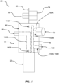
FIG. 6 is a cross-sectional view along line A-A ofFIG. 2 . -
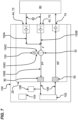
FIG. 7 is a schematic view generally illustrating portions of an embodiment of a fluid module according to teachings of the present disclosure. -
FIG. 8 is a representation generally illustrating embodiments of a fluid module, an aircraft, and a fluid source according to teachings of the present disclosure. -
FIG. 9 is a flow diagram generally illustrating an embodiment of a method of utilizing a fluid module according to teachings of the present disclosure. - Reference will now be made in detail to exemplary aspects of the present disclosure that are illustrated in the accompanying drawings. Wherever possible, the same reference numbers will be used throughout the drawings to refer to the same or like parts.
- Reference will now be made in detail to embodiments of the present disclosure, examples of which are described herein and illustrated in the accompanying drawings. While the present disclosure will be described in conjunction with embodiments and/or examples, they do not limit the present disclosure to these embodiments and/or examples. On the contrary, the present disclosure covers alternatives, modifications, and equivalents.
- Described herein is a fluid module configured to be attached to an aircraft to provide fluid from a ground source of fluid to an aircraft. Conventional solutions often include numerous bulky components for ground service of an aircraft. This disclosure contemplates a fluid module configured to combine all components necessary for ground service of the aircraft into a single module that is optimized for size and weight efficiency without compromising functionality.
- Certain aspects of the present disclosure relate to a fluid module that in certain examples can be mounted to an aircraft to provide a readily accessible and compact interface between a hydraulic system of the aircraft and a ground located source of hydraulic fluid. In certain examples, the fluid module can include a manifold defining a filter port for mounting a replaceable filter used to filter hydraulic fluid directed through the manifold from the source of hydraulic fluid to the hydraulic system of the aircraft. The manifold can include one or more inlets (e.g., first and second inlets) for connecting the source of hydraulic fluid to the manifold. The manifold can define one or more fluid inlet paths for directing hydraulic fluid from the inlet or inlets to the filtration location defined by the filter port. The inlet fluid paths can be configured to direct fluid to a "dirty" side of a filter media of the filter at which contamination can be collected. One-way valves can be provided for allowing flow through the manifold to travel through the inlet passage or passages only in a direct toward the filtration location thereby preventing back-flow toward the source of hydraulic fluid. The manifold also defines an outlet connected in fluid communication with the filtration location by an outlet path defined by the manifold. The outlet path can be configured to receive filtered fluid that has passed from the inlet passage through the filter media of the filter. The fluid module can also include a connection device (e.g., an adapter) for allowing a fluid return line from the hydraulic system of the aircraft to be connected to the source of hydraulic fluid (e.g., to a reservoir of the source of hydraulic fluid). The connection device can include a one-way valve for preventing back-flow from the source of hydraulic fluid toward the fluid return line of the aircraft. In one example, the connection device is mounted to an exterior flange of the fluid module. The connection device can include a first fluid connection interface for connecting the fluid return line to the connection device and a second fluid connection interface for connecting the source of hydraulic fluid to the connection device. Example fluid connection interfaces can include couplers, fittings, threaded connections, ferrules, hose clamp locations, or other structures. In one example, the first fluid connection interface provides a more permanent connection (e.g., a threaded connection) than the second fluid connection interface. In one example, the second fluid connection interface includes a quick-disconnect coupling (e.g., a coupling that can be coupled/decoupled without threading). In certain examples, an outlet fluid connection interface is provided at the outlet and inlet fluid connection interfaces are provided at the inlet or inlets. As described above, example fluid connection interfaces include couplers, ferrules, fittings, threaded connections, hose clamp locations and the like. In one example, the outlet fluid connection interface is more permanent (e.g., a threaded connection) than the inlet fluid connection interfaces. In one example, the inlet connection interfaces include quick-disconnect couplings (e.g., a coupling that can be coupled/decoupled without threading). In one example, the first fluid connection interface of the connection device and the outlet fluid connection interface face in a first direction, while the second fluid connection interface of the connection device and the inlet fluid connection interfaces face in an opposite second direction. In certain examples, the fluid module is configured such that when the fluid module is mounted to the aircraft, the first direction faces inwardly toward the aircraft while the second direction faces outwardly from the aircraft. In one example, the outlet/outlet passage of the manifold include a one-way valve that prevents back-flow from the hydraulic system of the aircraft to the manifold. This can protect the manifold and its components from pressure surges during flight.
- In embodiments, such as generally illustrated in
FIGS. 1-5 , afluid module 20 may include a manifold 30 and/or afilter unit 32. A manifold 30 may include afluid chamber 40, afirst inlet 42, asecond inlet 44, afilter port 46, and/or anoutlet 50. Thefirst inlet 42 and/or thesecond inlet 44 may be in fluid communication with thefluid chamber 40 and/or thefilter port 46. For example, fluid provided to thefirst inlet 42 and/or thesecond inlet 44 may be provided to thefluid chamber 40. Thefluid chamber 40 may be in fluid communication with thefilter port 46. Thefilter port 46 may be configured for connection with thefilter unit 32, such as to facilitate filtering of the fluid received via thefirst inlet 42 and/or thesecond inlet 44. Thefilter unit 32 and/or thefilter port 46 may be in fluid communication with theoutlet 50. For example, fluid that has been filtered by thefilter unit 32 may be provided to theoutlet 50. Thefilter unit 32 may include a filter element 34 (see, e.g.,FIG. 6 ). Thefilter port 46 may, in some configurations include threads for engaging a filter bowl of thefilter unit 32 and/or a shuttle valve to facilitate removal of the filter bowl (e.g., to limit/prevent leaks). - With embodiments, a manifold 30 may include one or more of a variety of shapes, sizes, configurations, and/or materials. For example, the manifold 30 may include a substantially
cylindrical body 60 and/or aflange 62 that may extend from thebody 60. Theflange 62, at least in some configurations, may be substantially planar, and/or may extend axially from an axial end of thebody 60. Theflange 62 may, for example, be parallel to a plane that bisects the body 60 (e.g., into inner and outer sides). Theflange 62 may be shorter, in an axial direction, than thebody 60. For example and without limitation, the axial length of theflange 62 may be between about 25% and about 75% of the axial length of thebody 60. In some instances, the axial length of theflange 62 may be about half of the axial length of thebody 60. The width of theflange 62 may be about the same as or less than the diameter of thebody 60, or larger than the diameter of thebody 60. The manifold 30 may, for example and without limitation, comprise metal (e.g., stainless steel) and/or may be formed via machining and/or additive manufacturing. The manifold 30 may include a central axis C (see, e.g.,FIG. 3 ) that may be aligned with and/or parallel to an axial direction of thefluid module 20. - With embodiments, a
fluid module 20 may include one or more couplings, such as afirst coupling 70, asecond coupling 72, and/or athird coupling 74. Thefirst coupling 70 may be connected to thefirst inlet 42. Thesecond coupling 72 may be connected to thesecond inlet 44. Thefirst coupling 70 may, for example, include a quick-disconnect (QD) coupling and/or may be configured for connection with afluid source 80 that may be configured to provide pressurized fluid for an aircraft 100 (see, e.g.,FIGS. 7 and8 ). For example and without limitation, anaircraft 100 may include one ormore actuators 102 that may utilize and/or be powered via pressurized fluid. When theaircraft 100 is on the ground, it may be desirable to operate the one ormore actuators 102 without using the engines orother power sources 104 of theaircraft 100. Thefluid source 80, which may include a ground cart, may be configured to provide such pressurized fluid instead of via aircraft fluid systems that may rely on the engines/power sources 104. For example, thefluid source 80 may include a pump and/or a pressurized tank. Thesecond coupling 72 may, for example, include a fill valve, a QD coupling, and/or may be configured for connection with thefluid source 80, which may be configured to provide low pressure or unpressurized fluid to theaircraft 100. For example, if an aircraft fluid system/reservoir 108 has a low fluid level, thefluid source 80 may provide fluid to theaircraft 100 via thesecond coupling 72 to increase the fluid level. In some configurations, afluid module 20 may not include asecond inlet 44/asecond coupling 72 and/or thefirst coupling 70 may be utilized to fill areservoir 108. Thethird coupling 74 may be connected to theflange 62 and/or may include a QD coupling, among other configurations. Thethird coupling 74 may, for example, be configured for connection with afluid source 80, such as to provide return fluid from theaircraft 100 to thefluid source 80. - In embodiments, a
fluid module 20 may include one or more fluid interfaces, such as afirst interface 90 and/or asecond interface 92. Aninterface fluid conduit 106 of anaircraft 100. Thefirst interface 90 may be connected to theoutlet 50 of the manifold 30 and may be configured to provide filtered fluid (e.g., pressurized or fill) from the manifold to one or morefluid conduits 106, reservoirs, and/or to one ormore actuators 102 of the aircraft. Thesecond interface 92 may be connected to theflange 62 and/or thethird coupling 74, such as to receive return fluid from theaircraft 100 for providing/returning to thefluid source 80. - With embodiments, a
fluid module 20 may include anindicator 120 that may be configured to provide an indication regarding the status of thefilter unit 32 and/or the differential pressure across thefilter unit 32, which may correspond to how full/clogged thefilter unit 32 is. For example, theindicator 120 may be in fluid communication with thechamber 40/thefirst inlet 42/thesecond inlet 44 and theoutlet 50, such to sense a differential pressure between thechamber 40/thefirst inlet 42/thesecond inlet 44 and the outlet 50 (e.g., theindicator 120 may include a pressure sensor/indicator). The differential pressure may increase as thefilter unit 32 fills up with particles filtered out from the fluid. When the differential pressure reaches a threshold, the indicator may provide a visual indication (e.g., color change, movement, etc.), which may suggest that thefilter element 34 should be cleaned or replaced. - In embodiments, such as generally illustrated in
FIG. 2 , a manifold 30 may include afirst side 130 and asecond side 132. Thefirst side 130 may be configured to face outward, such as for connection with thefluid source 80. Thesecond side 132 may be configured to face inward, such as for connection with one ormore actuators 102 and/orfluid conduits 106. In some configurations, thefirst coupling 70, thesecond coupling 72, thethird coupling 74, and/or theindicator 120 may extend from thefirst side 130, and/or thefirst interface 90 and/or thesecond interface 92 may extend from thesecond side 132. For example and without limitation, thefirst coupling 70 and thesecond coupling 72 may extend from thebody 60 of the manifold 30 at an angle relative to each other (e.g., an acute or right angle), the third coupling 7 4 and/or theindicator 120 may extend outward (e.g., perpendicular to the flange 62), and/or thefirst interface 90 and/or thesecond interface 92 may extend inward (e.g., perpendicular to theflange 62 and/or anti parallel to the third coupling 74). Thethird coupling 74, thefirst interface 90, thesecond interface 92, and/or theindicator 120 may be aligned in an axial direction such that their centerlines are aligned with a plane B extending in the axial direction and perpendicular to theflange 62. Thethird coupling 74 and thesecond interface 92 may extend in opposite directions from theflange 62. In some instances, thefirst coupling 70, thesecond coupling 72, and thethird coupling 74 may extend in three different directions. - Embodiments of a
fluid module 20 may be smaller, lighter, and/or less complex than other designs. For example and without limitation, one possible embodiment of afluid module 20 may have a length (e.g., in the axial direction) of about 12-14 inches or less, a width (e.g., in a radial direction aligned with the flange 62) of about 4-6 inches or less, and/or a depth (e.g., in an inward/outward radial direction perpendicular to the flange 62) of about 6-8 inches or less. In an embodiment, afluid module 20 may be less than 14 inches in a first direction, less than 6 inches in a second direction, and less than 8 inches in a third direction. Additionally or alternatively, the volume of an envelope (e.g., a rectangular prism encompassing the fluid module 20) of such an example embodiment may be about 700 cubic inches or less, about 500 cubic inches or less, or other volumes. - With embodiments, such as generally illustrated in
FIGS. 1-5 , a manifold 30 may include one or more mounting tabs, such as mountingtabs tabs 140A-D may be configured for mounting amodule 20 to a mounting surface, such as with anaircraft 100. The mountingtabs 140A-D may, for example, extend outward from thebody 60, such as in a generally radial direction. The mountingtabs 140A-D may, for example and without limitation, include respective through holes, and/or may be generally rectangular, may include a first pair of mountingtabs 140A-B and a second pair of mountingtabs 140C-D that extend in opposite directions from the manifold 30. In some configurations, the mountingtabs 140A-D may be substantially aligned with a plane of and/or parallel with theflange 62. - In embodiments, such as generally illustrated in
FIG. 6 , a manifold 30 may include one or more internal fluid passages, such as internal fluid passages 1 50A-E. Afirst fluid passage 150A may extend from thefirst inlet 42 to thefilter port 46, such as to provide fluid F (e.g., pressurized fluid) from thefirst inlet 42 and/or thefirst coupling 70 to thefilter unit 32. Asecond fluid passage 150B may extend from thesecond inlet 44 to thefilter port 46, such as to provide fluid F (e.g., fill fluid) from thesecond inlet 44 and/or thesecond coupling 72 to thefilter unit 32. A third fluid passage 1 50C may extend from thefirst fluid passage 150A, thesecond fluid passage 150B, and/or the filter unit 32 (e.g., at or about an input) to theindicator 120. Afourth fluid passage 150D may extend from afifth fluid passage 150E and/or the filter unit 32 (e.g., at or about an output) to theindicator 120. For example and without limitation, thefluid passages 150C-D may be configured to allow theindicator 120 to sense a differential pressure across thefilter unit 32. Thefifth fluid passage 150E may extend from thefilter unit 32 to theoutlet 50 and/or thefirst interface 90, such as to provide filtered fluid FF from thefilter unit 32 to theaircraft 100, one ormore actuators 102, and/or one or morefluid conduits 106. Achamber 40 may be formed, at least in part, via one or more fluid passages, such asfluid passages - With embodiments, such as generally illustrated in
FIGS. 7 and8 , afluid source 80, which may include a ground cart (e.g., an airport hydraulic fluid cart), may be connected for fluid communication with afirst inlet 42 of themodule 20 via afirst coupling 70, asecond inlet 44 of themodule 20 via asecond coupling 72, and/or a second/return interface 92 via athird coupling 74. One or more of thefirst coupling 70, thesecond coupling 72, and/or thethird coupling 74 may include a check valve and/or a QD connection. An input of thefilter unit 32 may be connected for fluid communication with thefirst inlet 42 via thefirst passage 150A and/or to thesecond inlet 44 via thesecond passage 150B. Anindicator 120 may be connected at or about the input of thefilter unit 32 and at or about the output of thefilter unit 32. The output of thefilter unit 32 may be connected for fluid communication with afirst interface 90 that may be connected to anaircraft 100 and/or afluid conduit 106 and/or anactuator 102 thereof. Asecond interface 92 of thefluid module 20 may be connected for fluid communication with theaircraft 100 and/or athird coupling 74 of thefluid module 20. Thefluid module 20 may be mounted on or in anaircraft 100 to facilitate fluid communication with afluid source 80. - Referring again to
FIG. 3 , in embodiments, a fluid module may include one or morefluid components 160, such as one or more sampling valves, pressure relief switches, gauges, and/or displays, among others. The one or morefluid component 160 may, in some configurations, be connected and/or mounted to theflange 62. - With embodiments, such as generally illustrated in
FIG. 9 , amethod 200 of utilizing afluid module 20, which may be mounted in/on anaircraft 100, may include connecting thefluid module 20 to a fluid source 80 (block 202). Connecting thefluid module 20 to thefluid source 80 may include connecting one or more fluid conduits 82 (e.g., hoses, tubes, etc.) to afirst coupling 70, asecond coupling 72, and/or athird coupling 74 of thefluid module 20. Themethod 200 may include providing fluid F from the fluid source 80 (e.g., a ground fluid source) to themodule 20, such as to thefirst coupling 70 or the second coupling 72 (block 204). The provided fluid F may include pressurized fluid or fill fluid. Themethod 200 may include providing fluid F from thefirst coupling 70 or thesecond coupling 72 to a filter unit 32 (block 206), such as via one or moreinternal passages 150A-E and/or achamber 40 of amanifold 30 of thefluid module 20. Themethod 200 may include filtering the fluid via the filter unit 32 (block 208) and/or providing the filtered fluid FF to anoutlet 50 of the manifold 30, one ormore actuators 102 of the aircraft 100 (e.g., for pressurized fluid), one or morefluid conduits 106 of theaircraft 100, and/or areservoir 108 of the aircraft (e.g., for fill fluid) (block 210). Themethod 200 may include operating one or more actuators 102 (e.g., hydraulic motors, cylinders, pistons, etc.) with the filtered fluid FF (block 212), such as if thefluid source 80 provides pressurized fluid. Themethod 200 may include providing return fluid RF (e.g., from the one or more actuators 102) to the fluid module 20 (block 214) and/or from thefluid module 20 to the fluid source 80 (block 216). For example, return fluid RF may be provided from anactuator 102 to asecond interface 92 of thefluid module 20, from thesecond interface 92 to athird coupling 74, and/or from thethird coupling 74 to thefluid source 80. One or more blocks of themethod 200 may be repeated (see, e.g., arrow 220), such as to continue to provide filtered and pressurized fluid to anaircraft 100 from a ground-basedfluid source 80 to avoid utilizing the engines or other power sources 104 (e.g., batteries) of theaircraft 100. Additionally or alternatively, one or more blocks of themethod 200 may be omitted. For example, if afluid module 20 is being utilized to fill areservoir 108 of anaircraft 100 and not to operate one ormore actuators 102, themethod 200 may not include blocks 212-216 and/or blocks 204-210 may be repeated (see, e.g., arrow 222). In some configurations, block 210 may include providing fluid to one ormore actuators 102 and one ormore reservoirs 108. - Various examples/embodiments are described herein for various apparatuses, systems, and/or methods. Numerous specific details are set forth to provide a thorough understanding of the overall structure, function, manufacture, and use of the examples/embodiments as described in the specification and illustrated in the accompanying drawings. It will be understood by those skilled in the art, however, that the examples/embodiments may be practiced without such specific details. In other instances, well-known operations, components, and elements have not been described in detail so as not to obscure the examples/embodiments described in the specification. Those of ordinary skill in the art will understand that the examples/embodiments described and illustrated herein are non-limiting examples, and thus it can be appreciated that the specific structural and functional details disclosed herein may be representative and do not necessarily limit the scope of the embodiments.
- Reference throughout the specification to "examples, "in examples," "with examples," "various embodiments," "with embodiments," "in embodiments," or "an embodiment," or the like, means that a particular feature, structure, or characteristic described in connection with the example/embodiment is included in at least one embodiment. Thus, appearances of the phrases "examples, "in examples," "with examples," "in various embodiments," "with embodiments," "in embodiments," or "an embodiment," or the like, in places throughout the specification are not necessarily all referring to the same embodiment. Furthermore, the particular features, structures, or characteristics may be combined in any suitable manner in one or more examples/embodiments. Thus, the particular features, structures, or characteristics illustrated or described in connection with one embodiment/example may be combined, in whole or in part, with the features, structures, functions, and/or characteristics of one or more other embodiments/examples without limitation given that such combination is not illogical or non-functional. Moreover, many modifications may be made to adapt a particular situation or material to the teachings of the present disclosure without departing from the scope thereof.
- It should be understood that references to a single element are not necessarily so limited and may include one or more of such element. Any directional references (e.g., plus, minus, upper, lower, upward, downward, left, right, leftward, rightward, top, bottom, above, below, vertical, horizontal, clockwise, and counterclockwise) are only used for identification purposes to aid the reader's understanding of the present disclosure, and do not create limitations, particularly as to the position, orientation, or use of examples/embodiments.
- Joinder references (e.g., attached, coupled, connected, and the like) are to be construed broadly and may include intermediate members between a connection of elements, relative movement between elements, direct connections, indirect connections, fixed connections, movable connections, operative connections, indirect contact, and/or direct contact. As such, joinder references do not necessarily imply that two elements are directly connected/coupled and in fixed relation to each other. Connections of electrical components, if any, may include mechanical connections, electrical connections, wired connections, and/or wireless connections, among others. Uses of "e.g." and "such as" in the specification are to be construed broadly and are used to provide non-limiting examples of embodiments of the disclosure, and the disclosure is not limited to such examples. Uses of "and" and "or" are to be construed broadly (e.g., to be treated as "and/or"). For example and without limitation, uses of "and" do not necessarily require all elements or features listed, and uses of "or" are inclusive unless such a construction would be illogical.
- While processes, systems, and methods may be described herein in connection with one or more steps in a particular sequence, it should be understood that such methods may be practiced with the steps in a different order, with certain steps performed simultaneously, with additional steps, and/or with certain described steps omitted.
- All matter contained in the above description or shown in the accompanying drawings shall be interpreted as illustrative only and not limiting. Changes in detail or structure may be made without departing from the present disclosure.
- Having described the preferred aspects and implementations of the present disclosure, modifications and equivalents of the disclosed concepts may readily occur to one skilled in the art. However, it is intended that such modifications and equivalents be included within the scope of the claims which are appended hereto.
- Inventive aspects of the disclosure are further listed below:
- Aspect 1. A fluid module configured to be connected to an aircraft, comprising: a manifold configured to direct fluid flow from an inlet to an outlet, the outlet configured to be connected to a hydraulic system of the aircraft and the inlet configured to be connected to a source of fluid such as a ground cart, the manifold comprising: a filter port adapted to receive a filter unit; the first inlet in fluid communication with the filter port; and the outlet in fluid communication with the filter port.
- Aspect 2. The fluid module of aspect 1, wherein there is a first coupling at the first inlet and a fluid connection interface at the outlet.
- Aspect 3. The fluid module of aspect 1 or aspect 2, further comprising a second inlet connected to a second coupling, the first inlet configured to be connected to a first pressure source and the second inlet configured to be connected to a second pressure source, the first pressure source and the second pressure source having different pressures.
- Aspect 4. The fluid module of any of aspects 1-3, further comprising a flange extending from a main body of the manifold, the flange comprising a third coupling configured to be connected to the fluid source to provide return fluid from the aircraft to the fluid source.
- Aspect 5. The fluid module of aspect 4, wherein the first coupling, the second coupling, and the third coupling are quick-disconnect couplings.
- Aspect 6. The fluid module of any of aspects 1-5, wherein the fluid module is part of the ground cart.
- Aspect 7. The fluid module of any of aspects 3-6, wherein the filter port is connected to a filter unit, wherein the filter unit is in fluid communication with at least one of the first inlet and the second inlet.
- Aspect 8. The fluid module of any of aspects 1-7, wherein the manifold is cylindrical.
- Aspect 9. The fluid module of any of aspects 4-8, wherein the flange is planar and extends axially from an axial end of the manifold.
- Aspect 10. The fluid module of any of aspects 1-9, wherein the fluid module has a weight of less than 12 pounds.
- Aspect 11. The fluid module of any of aspects 1-10, wherein fluid module is less than 14 inches in a first direction, less than 6 inches in a second direction, and less than 8 inches in a third direction.
- Aspect 12. The fluid module of any of aspects 3-11, wherein the first coupling and the second coupling are disposed at an acute angle relative to each other.
- Aspect 13. The fluid module of any of aspects 1-12, wherein the manifold includes a plurality of mounting tabs extending radially outward from the manifold, the mounting tabs configured to mount the fluid module to an aircraft.
- Aspect 14. The fluid module of any of aspects 3-13, wherein the first inlet is in fluid communication with the filter port via a first internal fluid passage of the manifold; the second inlet is in fluid communication with the filter port via a second internal fluid passage of the manifold; and the outlet is in fluid communication with the filter port via a third internal fluid passage of the manifold.
- Aspect 15. The fluid module of any of aspects 7-14, further comprising an indicator configured to provide an indication regarding a status of the filter unit or a differential pressure across the filter unit.
- Aspect 16. The fluid module of aspect 15, wherein the indicator is in fluid communication with the outlet and at least one of the first inlet and the second inlet.
- Aspect 17. A method of utilizing the fluid module of any of aspects 7-16 comprising: providing fluid from the fluid source to the first coupling or the second coupling; providing the fluid from the first coupling or the second coupling to the filter unit; filtering the fluid via the filter unit; providing the filtered fluid from the filter unit to the outlet; and providing the filtered fluid from the outlet to one or more components, a reservoir of the aircraft, or combinations thereof.
- Aspect 18. The method of aspect 17, wherein the fluid includes hydraulic fluid, and the one or more components comprise one or more hydraulic actuators.
- Aspect 19. The method of aspect 17 or aspect 18, further comprising providing return fluid from the one or more hydraulic actuators or the aircraft reservoir to the fluid source via the third coupling of the fluid module.
-
Aspect 20. The method of any of aspects 17-19, wherein the fluid provided from the first coupling is pressurized fluid and the fluid provided from the second coupling is low pressure or unpressurized fluid. - Aspect 21. The method of any of aspect 17-20, further comprising performing the method one or more times to continually provide fluid to the one or more components, a reservoir of the aircraft, or combinations thereof.
- Aspect 22. The method of aspect 18, wherein the one or more actuators comprise hydraulic motors, cylinders, pistons, or combinations thereof.
Claims (15)
- A fluid module, comprisinga manifold including:a filter port adapted for mounting a filter unit to the manifold;a first inlet in fluid communication with the filter port; andan outlet in fluid communication with the filter port;a first coupling connected to the first inlet; anda fluid interface connected to the outlet.
- The fluid module of claim 1, including a second coupling;wherein the manifold includes a second inlet; andthe second coupling is connected to the second inlet.
- The fluid module of claim 2, including a third coupling;wherein the manifold includes a flange; andthe third coupling is connected to the flange.
- The fluid module of claim 3, including a second fluid interface;wherein the fluid interface and the second fluid interface are disposed at a first side of the manifold; andthe first coupling, the second coupling, and the third coupling are disposed at a second side of the manifold,wherein the flange is planar and extends axially from an axial end of the manifold.
- The fluid module of claim 1, wherein the fluid module has a weight of less than 12 pounds.
- The fluid module of claim 1, wherein fluid module is less than 14 inches in a first direction, less than 6 inches in a second direction, and less than 8 inches in a third direction.
- The fluid module of claim 1, wherein the manifold includes a plurality of mounting tabs extending radially outward from the manifold.
- The fluid module of claim 7, wherein the plurality of mounting tabs are aligned with the flange.
- The fluid module of claim 1, wherein the first inlet is in fluid communication with the filter port via a first internal fluid passage of the manifold;the second inlet is in fluid communication with the filter port via a second internal fluid passage of the manifold; andthe outlet is in fluid communication with the filter port via a third internal fluid passage of the manifold.
- The fluid module of claim 1, including an indicator connected to the manifold and in fluid communication with the outlet and at least one of the first inlet and the second inlet; wherein the indicator is configured to provide an indication of a differential pressure across the filter.
- An aircraft including the fluid module of claim 1.
- The aircraft including the fluid module of any of claims 1-11, comprising one or more hydraulic actuators;
wherein the fluid interface is in fluid communication with the one or more hydraulic actuators. - A method of utilizing the fluid module of claim 2, the fluid module mounted to an aircraft, the method comprising:providing fluid from a ground fluid source to the first coupling or the second coupling;providing the fluid from the first coupling or the second coupling to the filter;filtering the fluid via the filter;providing the filtered fluid from the filter to the outlet and the fluid interface; andproviding the filtered fluid from the fluid interface to one or more components and/or a reservoir of the aircraft.
- The method of claim 13, wherein the fluid includes hydraulic fluid; and
the one or more components include comprise one or more hydraulic actuators. - The method of claim 14, comprising operating the one or more components via the filtered fluid; and
providing return fluid from the one or more components to the ground fluid source via a second interface of the fluid module and the third coupling.
Applications Claiming Priority (1)
| Application Number | Priority Date | Filing Date | Title |
|---|---|---|---|
| US202263305382P | 2022-02-01 | 2022-02-01 |
Publications (1)
| Publication Number | Publication Date |
|---|---|
| EP4219317A1 true EP4219317A1 (en) | 2023-08-02 |
Family
ID=85158825
Family Applications (1)
| Application Number | Title | Priority Date | Filing Date |
|---|---|---|---|
| EP23154526.0A Pending EP4219317A1 (en) | 2022-02-01 | 2023-02-01 | Fluid module |
Country Status (2)
| Country | Link |
|---|---|
| US (1) | US12416320B2 (en) |
| EP (1) | EP4219317A1 (en) |
Citations (2)
| Publication number | Priority date | Publication date | Assignee | Title |
|---|---|---|---|---|
| KR20050011223A (en) * | 2003-07-22 | 2005-01-29 | 국방과학연구소 | Hydraulic power package for aircraft |
| US20200340504A1 (en) * | 2019-04-23 | 2020-10-29 | The Boeing Company | Prediction of hydraulic pump health and failure |
Family Cites Families (6)
| Publication number | Priority date | Publication date | Assignee | Title |
|---|---|---|---|---|
| US4690621A (en) | 1986-04-15 | 1987-09-01 | Advanced Control Engineering | Filter pump head assembly |
| GB8909592D0 (en) | 1989-04-26 | 1989-06-14 | Starling Andrew | Portable water filter |
| US5705065A (en) | 1996-09-06 | 1998-01-06 | Conbraco Industries, Inc. | Sea water strainer |
| GB201516591D0 (en) | 2015-09-18 | 2015-11-04 | Fresh Water Filter Company The Ltd | Filter head |
| US11725781B2 (en) | 2019-02-11 | 2023-08-15 | Watts Regulator Co. | Pressure relief cover assembly |
| EP4082898B1 (en) * | 2021-04-30 | 2024-07-17 | Airbus Operations GmbH | Control system for an aircraft |
-
2023
- 2023-02-01 EP EP23154526.0A patent/EP4219317A1/en active Pending
- 2023-02-01 US US18/104,677 patent/US12416320B2/en active Active
Patent Citations (2)
| Publication number | Priority date | Publication date | Assignee | Title |
|---|---|---|---|---|
| KR20050011223A (en) * | 2003-07-22 | 2005-01-29 | 국방과학연구소 | Hydraulic power package for aircraft |
| US20200340504A1 (en) * | 2019-04-23 | 2020-10-29 | The Boeing Company | Prediction of hydraulic pump health and failure |
Non-Patent Citations (1)
| Title |
|---|
| "Rücklauf-Saugfilter RKM. Die neue Generation", 1 April 2010 (2010-04-01), 66280 Sulzbach (Saar), Germany, pages 1 - 10, XP055060984, Retrieved from the Internet <URL:www.hydac.com> [retrieved on 20130424] * |
Also Published As
| Publication number | Publication date |
|---|---|
| US20230242278A1 (en) | 2023-08-03 |
| US12416320B2 (en) | 2025-09-16 |
Similar Documents
| Publication | Publication Date | Title |
|---|---|---|
| US20180058631A1 (en) | Split pressure vessel for two flow processing | |
| US8202422B2 (en) | Fluid system | |
| US20140373940A1 (en) | Fluid drain manifold | |
| EP3423353A1 (en) | Redundant vehicle control systems | |
| US20050142012A1 (en) | Rodder pump | |
| US8211302B2 (en) | Filter assembly | |
| US12416320B2 (en) | Fluid module | |
| CN201333348Y (en) | Pipeline filter | |
| US12421962B2 (en) | Hydraulic power pack with adjustable mounting arrangement | |
| CN217055758U (en) | Hydraulic station | |
| CN217056541U (en) | Compact servo electro-hydraulic actuator | |
| CN101400998B (en) | Hydraulic circuit control element for spring applied-hydraulically released brake | |
| CN113994103B (en) | Hydraulic control block and servo hydraulic axis having the same | |
| CN214499638U (en) | A test device for hydraulic steering wheel of aircraft control | |
| US20070209983A1 (en) | Hydraulic lubrication filter assembly | |
| EP3060806A1 (en) | Scalable pumping mechanism utilizing anti-synchronized poly-diaphragm stack | |
| CN108506266B (en) | Plug-in type proportional valve | |
| EP4646533A1 (en) | Integrated hydraulic pump-manifold assembly | |
| US11583792B2 (en) | Fluid filter device | |
| CN221471122U (en) | Compatible filter | |
| RU2296884C2 (en) | Submersible hydraulic pumping unit | |
| CN213685365U (en) | Multifunctional valve for petroleum equipment | |
| CN109078379B (en) | Oil supply device | |
| US11401957B2 (en) | Integrated gear pump in remote mounted hydraulic control unit | |
| CN209020030U (en) | A kind of fueller |
Legal Events
| Date | Code | Title | Description |
|---|---|---|---|
| PUAI | Public reference made under article 153(3) epc to a published international application that has entered the european phase |
Free format text: ORIGINAL CODE: 0009012 |
|
| STAA | Information on the status of an ep patent application or granted ep patent |
Free format text: STATUS: REQUEST FOR EXAMINATION WAS MADE |
|
| 17P | Request for examination filed |
Effective date: 20230201 |
|
| AK | Designated contracting states |
Kind code of ref document: A1 Designated state(s): AL AT BE BG CH CY CZ DE DK EE ES FI FR GB GR HR HU IE IS IT LI LT LU LV MC ME MK MT NL NO PL PT RO RS SE SI SK SM TR |
|
| STAA | Information on the status of an ep patent application or granted ep patent |
Free format text: STATUS: EXAMINATION IS IN PROGRESS |
|
| 17Q | First examination report despatched |
Effective date: 20240709 |
|
| GRAP | Despatch of communication of intention to grant a patent |
Free format text: ORIGINAL CODE: EPIDOSNIGR1 |
|
| STAA | Information on the status of an ep patent application or granted ep patent |
Free format text: STATUS: GRANT OF PATENT IS INTENDED |
|
| RIC1 | Information provided on ipc code assigned before grant |
Ipc: B64D 41/00 20060101AFI20260211BHEP Ipc: F15B 19/00 20060101ALN20260211BHEP |
|
| INTG | Intention to grant announced |
Effective date: 20260310 |