EP4219315A1 - Aircraft skin heat exchanger - Google Patents
Aircraft skin heat exchanger Download PDFInfo
- Publication number
- EP4219315A1 EP4219315A1 EP23152943.9A EP23152943A EP4219315A1 EP 4219315 A1 EP4219315 A1 EP 4219315A1 EP 23152943 A EP23152943 A EP 23152943A EP 4219315 A1 EP4219315 A1 EP 4219315A1
- Authority
- EP
- European Patent Office
- Prior art keywords
- heat exchanger
- aircraft
- skin
- assembly
- aircraft structure
- Prior art date
- Legal status (The legal status is an assumption and is not a legal conclusion. Google has not performed a legal analysis and makes no representation as to the accuracy of the status listed.)
- Granted
Links
Images

Classifications
-
- F—MECHANICAL ENGINEERING; LIGHTING; HEATING; WEAPONS; BLASTING
- F02—COMBUSTION ENGINES; HOT-GAS OR COMBUSTION-PRODUCT ENGINE PLANTS
- F02C—GAS-TURBINE PLANTS; AIR INTAKES FOR JET-PROPULSION PLANTS; CONTROLLING FUEL SUPPLY IN AIR-BREATHING JET-PROPULSION PLANTS
- F02C7/00—Features, components parts, details or accessories, not provided for in, or of interest apart form groups F02C1/00 - F02C6/00; Air intakes for jet-propulsion plants
- F02C7/12—Cooling of plants
-
- B—PERFORMING OPERATIONS; TRANSPORTING
- B64—AIRCRAFT; AVIATION; COSMONAUTICS
- B64D—EQUIPMENT FOR FITTING IN OR TO AIRCRAFT; FLIGHT SUITS; PARACHUTES; ARRANGEMENT OR MOUNTING OF POWER PLANTS OR PROPULSION TRANSMISSIONS IN AIRCRAFT
- B64D33/00—Arrangement in aircraft of power plant parts or auxiliaries not otherwise provided for
- B64D33/08—Arrangement in aircraft of power plant parts or auxiliaries not otherwise provided for of power plant cooling systems
- B64D33/10—Radiator arrangement
-
- B—PERFORMING OPERATIONS; TRANSPORTING
- B64—AIRCRAFT; AVIATION; COSMONAUTICS
- B64D—EQUIPMENT FOR FITTING IN OR TO AIRCRAFT; FLIGHT SUITS; PARACHUTES; ARRANGEMENT OR MOUNTING OF POWER PLANTS OR PROPULSION TRANSMISSIONS IN AIRCRAFT
- B64D33/00—Arrangement in aircraft of power plant parts or auxiliaries not otherwise provided for
- B64D33/08—Arrangement in aircraft of power plant parts or auxiliaries not otherwise provided for of power plant cooling systems
-
- F—MECHANICAL ENGINEERING; LIGHTING; HEATING; WEAPONS; BLASTING
- F28—HEAT EXCHANGE IN GENERAL
- F28D—HEAT-EXCHANGE APPARATUS, NOT PROVIDED FOR IN ANOTHER SUBCLASS, IN WHICH THE HEAT-EXCHANGE MEDIA DO NOT COME INTO DIRECT CONTACT
- F28D7/00—Heat-exchange apparatus having stationary tubular conduit assemblies for both heat-exchange media, the media being in contact with different sides of a conduit wall
- F28D7/0041—Heat-exchange apparatus having stationary tubular conduit assemblies for both heat-exchange media, the media being in contact with different sides of a conduit wall the conduits for only one medium being tubes having parts touching each other or tubes assembled in panel form
-
- B—PERFORMING OPERATIONS; TRANSPORTING
- B64—AIRCRAFT; AVIATION; COSMONAUTICS
- B64C—AEROPLANES; HELICOPTERS
- B64C1/00—Fuselages; Constructional features common to fuselages, wings, stabilising surfaces or the like
- B64C1/06—Frames; Stringers; Longerons ; Fuselage sections
- B64C1/12—Construction or attachment of skin panels
-
- B—PERFORMING OPERATIONS; TRANSPORTING
- B64—AIRCRAFT; AVIATION; COSMONAUTICS
- B64C—AEROPLANES; HELICOPTERS
- B64C3/00—Wings
- B64C3/26—Construction, shape, or attachment of separate skins, e.g. panels
-
- B—PERFORMING OPERATIONS; TRANSPORTING
- B64—AIRCRAFT; AVIATION; COSMONAUTICS
- B64D—EQUIPMENT FOR FITTING IN OR TO AIRCRAFT; FLIGHT SUITS; PARACHUTES; ARRANGEMENT OR MOUNTING OF POWER PLANTS OR PROPULSION TRANSMISSIONS IN AIRCRAFT
- B64D15/00—De-icing or preventing icing on exterior surfaces of aircraft
- B64D15/02—De-icing or preventing icing on exterior surfaces of aircraft by ducted hot gas or liquid
-
- B—PERFORMING OPERATIONS; TRANSPORTING
- B64—AIRCRAFT; AVIATION; COSMONAUTICS
- B64D—EQUIPMENT FOR FITTING IN OR TO AIRCRAFT; FLIGHT SUITS; PARACHUTES; ARRANGEMENT OR MOUNTING OF POWER PLANTS OR PROPULSION TRANSMISSIONS IN AIRCRAFT
- B64D33/00—Arrangement in aircraft of power plant parts or auxiliaries not otherwise provided for
- B64D33/02—Arrangement in aircraft of power plant parts or auxiliaries not otherwise provided for of combustion air intakes
- B64D2033/024—Arrangement in aircraft of power plant parts or auxiliaries not otherwise provided for of combustion air intakes comprising cooling means
-
- F—MECHANICAL ENGINEERING; LIGHTING; HEATING; WEAPONS; BLASTING
- F05—INDEXING SCHEMES RELATING TO ENGINES OR PUMPS IN VARIOUS SUBCLASSES OF CLASSES F01-F04
- F05D—INDEXING SCHEME FOR ASPECTS RELATING TO NON-POSITIVE-DISPLACEMENT MACHINES OR ENGINES, GAS-TURBINES OR JET-PROPULSION PLANTS
- F05D2260/00—Function
- F05D2260/20—Heat transfer, e.g. cooling
- F05D2260/213—Heat transfer, e.g. cooling by the provision of a heat exchanger within the cooling circuit
Definitions
- Aircraft propulsion systems use a gas turbine engine that burns carbon based fuels.
- the aircraft industry desires to significantly reduce carbon emissions produced by aircraft propulsion systems.
- Engine systems disposed in an aircraft structure provides several benefits to engine operational efficiencies.
- incorporation of propulsion systems in an airframe present challenges to existing engine architectures.
- engine systems in an aircraft structure require ducts to communicate air to a propulsion system and exhaust waste gases and airflow. The size of such ducts are constrained by the aircraft structures and therefore may not provide a desired amount of airflow for cooling.
- An aircraft heat exchanger system includes a first heat exchanger assembly that is disposed in an inlet duct assembly, and a skin heat exchanger assembly is in thermal communication with an outer surface of an aircraft structure.
- the skin heat exchanger is in fluid communication with the first heat exchanger such that a working fluid is communicated therebetween.
- the skin heat exchanger is disposed along a bottom surface of the aircraft structure.
- the aircraft skin is in communication with a boundary layer flow of air.
- the first heat exchanger assembly includes a first outlet that communicates the working flow to an inlet of the skin heat exchanger.
- the skin heat exchanger includes a second outlet that communicates the working flow to the first heat exchanger assembly.
- the outer surface of the aircraft structure includes a bottom facing surface of the aircraft structure.
- the skin heat exchanger assembly is black.
- the heat exchanger assembly includes a second heat exchanger assembly that is disposed in the aircraft structure.
- the second heat exchanger is in fluid communication with the skin heat exchanger assembly.
- the aircraft structure includes at least one of an aircraft fuselage or an aircraft wing.
- An aircraft propulsion system includes a propulsor assembly that is disposed in an aircraft structure, an inlet duct for communicating airflow to the propulsor assembly.
- the inlet duct is disposed in the aircraft structure.
- a first heat exchanger assembly is disposed in the inlet duct assembly and in thermal transfer communication with airflow through the inlet duct.
- a skin heat exchanger assembly is in thermal communication with an outer surface of the aircraft structure.
- the skin heat exchanger assembly is in fluid communication with the first heat exchanger such that a working fluid is in communication therebetween.
- the skin heat exchanger is disposed along a bottom surface of the aircraft structure.
- the aircraft skin is in communication with a boundary layer flow of air.
- the first heat exchanger assembly includes a first outlet that communicates the working flow to an inlet of the skin heat exchanger.
- the skin heat exchanger includes a second outlet that communicates the working flow to the first heat exchanger assembly.
- the outer surface of the aircraft structure includes a bottom facing surface of the aircraft structure.
- the skin heat exchanger assembly is black.
- the aircraft propulsion system includes a second heat exchanger assembly that is disposed in the aircraft structure.
- the second heat exchanger is in fluid communication with the skin heat exchanger assembly.
- the aircraft structure includes at least one of an aircraft fuselage or an aircraft wing.
- a method of transferring thermal energy from an aircraft system working fluid includes transferring a first quantity of thermal energy with a first heat exchanger that is exposed to an inlet airflow through an air inlet of a propulsion system, and transferring a second quantity of thermal energy with a skin heat exchanger that is exposed to a boundary layer airflow along a surface of an aircraft structure.
- Figure 1 is a schematic view of an example aircraft heat exchanger system 20 disposed in an aircraft structure 22.
- the aircraft structure 22 may be the aircraft fuselage, a wing or other lifting structure.
- the disclosed example aircraft structure 22 includes an imbedded propulsor assembly 34 that receives air flow through an inlet duct 38.
- the propulsor assembly 34 creates a high energy propulsive flow that is exhausted through an exhaust duct 36.
- the propulsor assembly 34 is electrically powered
- the propulsor assembly 34 is a hybrid system that combines conventional combustion with electric power. It should be understood that although several types of propulsor assemblies are disclosed by way of example that any propulsor assembly would benefit from the heat exchanger system of this disclosure and are within the contemplation of this disclosure.
- the inlet duct 38 is sized to provide a desired amount of airflow to the propulsor assembly 34.
- the size over the inlet duct 38 is constrained by the size and shape of the aircraft structure 22. Accordingly, exposure to inlet airflow is limited by the size of the inlet duct 38.
- the constrained amount of airflow may limit a thermal capacity of a heat exchanger system required to cool and transfer heat produced by various aircraft systems 24.
- the aircraft systems 24 are shown schematically and may include lubricant, cooled cooling air, buffer cooling air and any other aircraft systems that transfer thermal energy to operate efficiently.
- a disclosed example heat exchanger system embodiment provides for increased thermal transfer capacity without modifications to the inlet duct 38.
- the example heat exchanger system 20 includes a first heat exchanger assembly 26 that is disposed in the inlet duct 38 and in thermal communication with an airflow 30 such that some airflow portion 35 is ingested into inlet duct 38.
- a skin heat exchanger assembly 28 is disposed along an outer bottom surface 40 of the aircraft structure 22 and in thermal communication with the airflow 30.
- the first heat exchanger assembly 26 and the skin heat exchanger assembly 28 are in fluid communication such that a working fluid 32 flows between the first heat exchanger assembly 26 and the skin heat exchanger 28.
- the working fluid 32 may include lubricant, fuel, hydraulic fluid as well as other flows that require thermal transfer of heat for efficient operation.
- a working fluid 32 is communicated first through the first heat exchanger assembly 26.
- the first heat exchanger assembly 26 transfers some quantity of thermal energy into the ingest airflow 35. The amount of thermal energy transferred may be sufficient to provide efficient operation. However, should additional thermal energy transfer be required, the working fluid 32 may be communicated to the skin heat exchanger assembly 26.
- the first heat exchanger 26 provides between 80% and 100% of the required thermal transfer capacity desired to sufficiently cool the working fluid 32 and the skin heat exchanger assembly provides the remaining thermal transfer capacity.
- the first heat exchanger 26 provides between 85% and 90% of the required thermal transfer capacity and the skin heat exchanger assembly provides the remaining 15% to 10%.
- other combinations of heat transfer capacity may be utilized and are within the contemplation of this disclosure.
- the example heat transfer system 20 includes the skin heat exchanger 28 disposed on a bottom surface of the aircraft structure 22.
- the skin heat exchanger 28 may have any shape, width and length that provides a desired thermal transfer capacity.
- the bottom surface 40 is typically not exposed to sunlight for extended periods of time and therefore is where the example skin heat exchanger 28 is mounted.
- the skin heat exchanger 28 is disposed on either side of the inlet 38.
- the offset placement of the skin heat exchanger 28 provides for non-heated boundary layer airflow 35 to be communicated into the inlet 38. Accordingly, airflow that has accepted heat through contact with the skin heat exchanger 28 is not substantially communicated into the inlet 38.
- the inlet 38 and thereby the first heat exchanger 26 is not provided with preheated air. It should be appreciated that it is within the contemplation and scope of this disclosure that the skin heat exchanger 28 may be located in other portions of the aircraft structure 22 that do not result in preheated air being communicated into the inlet 38.
- the thermal transfer of heat through the skin 44 provided by the disclosed skin heat exchanger 28 may be utilized to provide additional functions that make use of the communicated thermal energy.
- the skin heat exchanger 28 may provide anti-icing functions to prevent ice build up on portions of the aircraft structure 22.
- the skin heat exchanger 28 may be located, at least partially, on a leading edge of a wing or other lift generating structure of the aircraft structure 22 to provide an anti-icing function.
- other beneficial uses of the thermal energy transferred through the skin 44 may be utilized by providing a specific location of the skin heat exchanger 28 and are within the scope and contemplation of this disclosure.
- the skin heat exchanger 28 is placed in direct thermal transfer contact with a skin 44 of the aircraft structure 22.
- the direct contact with the skin 44 provides for thermal contact with the boundary layer flow 30 generated during aircraft operation.
- the working fluid 32 is flowed through the skin heat exchanger 28 in a forward direction that opposes the boundary layer flow 30. Stated another way, the working fluid 32 is flowed from an aft position toward a forward location that is opposite the flow 30 along the outer skin 44. Thermal energy illustrated by arrows 42 is transferred into the flow 30 and the cooled working fluid 32 is communicated back to the corresponding aircraft system 24.
- the skin heat exchanger 28 may be configured with multiple channels and passages for the working fluid 32 that are placed in thermal communication with the skin 44 and thereby the flow 30. It should be appreciated, that the skin heat exchanger 28 may be constructed of any applicable, known, thermal transfer materials and structures and all such materials and configurations are within the contemplation and scope of this disclosure.
- the disclosed example skin heat exchanger 28 is black to provide the advantageous thermal absorption properties associated with black body radiation.
- the black body of the skin heat exchanger is schematically indicated at 50.
- the skin heat exchanger 28 provides the increased thermal transfer capacity without introducing any additional aerodynamic drag. Furthermore, the skin heat exchanger is advantageous for cooling working fluids 32 that operate most efficiently when brought to ambient temperatures due to the large surface areas and high convective cooling rates during aircraft operation.
- the example heat exchange system 20 is shown with the working fluid 32 first being communicated to an inlet 46 of the skin heat exchanger assembly 28.
- the working fluid 32 is communicated forward and then back to the first heat exchanger assembly 26 disposed in the inlet duct 38. Accordingly, in this disclosed embodiment, the working fluid 32 is initially cooled and then cooled completely by the first heat exchanger assembly 26.
- the different configurations of working fluid flow 32 are possible to combine the thermal transfer capacities of the first heat exchanger assembly 26 and the skin heat exchanger assembly 28.
- other routing and communication of the working fluid between the first heat exchanger assembly 26 and the skin heat exchanger assembly 28 are possible and within the scope and contemplation of this disclosure.
- another heat exchanger system 52 is schematically shown and includes a second heat exchanger 54.
- the second heat exchanger 54 is in thermal communication with another cooling flow 56 and with the working fluid 32.
- the second heat exchanger assembly 54 may include a single heat exchanger or multiple heat exchangers that are utilized to further transfer thermal energy.
- the working fluid 32 is communicated from the aircraft systems 24 to the second heat exchanger 54 where it is cooled by the cooling flow 56.
- the working fluid 32 is then communicated to an inlet 48 of the first heat exchanger 26 for additional transfer of thermal energy.
- the working fluid 32 is then routed to inlet 46 for further thermal transfer by the skin heat exchanger 28.
- routing of the working fluid 32 may be controlled by various valves and conduits to select some combination of the heat exchangers required to transfer thermal energy as desired.
- the disclosed example heat exchanger systems provide for increased thermal efficiencies within the size constraint arising from alternate propulsor mounting and limited inlet duct size. Additionally, disclosed heat exchanger system embodiments provide for use of smaller heat exchangers in engine inlet ducts while the skin heat exchanger assembly 28 does not increase drag and thereby further provides for increased engine efficiencies.
Landscapes
- Engineering & Computer Science (AREA)
- Mechanical Engineering (AREA)
- Chemical & Material Sciences (AREA)
- Combustion & Propulsion (AREA)
- General Engineering & Computer Science (AREA)
- Aviation & Aerospace Engineering (AREA)
- Physics & Mathematics (AREA)
- Thermal Sciences (AREA)
- Heat-Exchange Devices With Radiators And Conduit Assemblies (AREA)
Abstract
Description
- Aircraft propulsion systems use a gas turbine engine that burns carbon based fuels. The aircraft industry desires to significantly reduce carbon emissions produced by aircraft propulsion systems. Engine systems disposed in an aircraft structure provides several benefits to engine operational efficiencies. However, incorporation of propulsion systems in an airframe present challenges to existing engine architectures. Moreover, engine systems in an aircraft structure require ducts to communicate air to a propulsion system and exhaust waste gases and airflow. The size of such ducts are constrained by the aircraft structures and therefore may not provide a desired amount of airflow for cooling.
- Although current engine systems have improved propulsive efficiency, aircraft engine manufacturers continue to seek further improvements to engine performance including improvements to thermal, transfer and propulsive efficiencies.
- An aircraft heat exchanger system according to an exemplary embodiment of this disclosure, among other possible things includes a first heat exchanger assembly that is disposed in an inlet duct assembly, and a skin heat exchanger assembly is in thermal communication with an outer surface of an aircraft structure. The skin heat exchanger is in fluid communication with the first heat exchanger such that a working fluid is communicated therebetween.
- In a further embodiment of the foregoing, the skin heat exchanger is disposed along a bottom surface of the aircraft structure.
- In a further embodiment of any of the foregoing, the aircraft skin is in communication with a boundary layer flow of air.
- In a further embodiment of any of the foregoing, the first heat exchanger assembly includes a first outlet that communicates the working flow to an inlet of the skin heat exchanger.
- In a further embodiment of any of the foregoing, the skin heat exchanger includes a second outlet that communicates the working flow to the first heat exchanger assembly.
- In a further embodiment of any of the foregoing, the outer surface of the aircraft structure includes a bottom facing surface of the aircraft structure.
- In a further embodiment of any of the foregoing, the skin heat exchanger assembly is black.
- In a further embodiment of any of the foregoing, the heat exchanger assembly includes a second heat exchanger assembly that is disposed in the aircraft structure. The second heat exchanger is in fluid communication with the skin heat exchanger assembly.
- In a further embodiment of any of the foregoing, the aircraft structure includes at least one of an aircraft fuselage or an aircraft wing.
- An aircraft propulsion system according to an exemplary embodiment of this disclosure, among other possible things includes a propulsor assembly that is disposed in an aircraft structure, an inlet duct for communicating airflow to the propulsor assembly. The inlet duct is disposed in the aircraft structure. A first heat exchanger assembly is disposed in the inlet duct assembly and in thermal transfer communication with airflow through the inlet duct. A skin heat exchanger assembly is in thermal communication with an outer surface of the aircraft structure.
- In a further embodiment of the foregoing, the skin heat exchanger assembly is in fluid communication with the first heat exchanger such that a working fluid is in communication therebetween.
- In a further embodiment of any of the foregoing, the skin heat exchanger is disposed along a bottom surface of the aircraft structure.
- In a further embodiment of any of the foregoing, the aircraft skin is in communication with a boundary layer flow of air.
- In a further embodiment of any of the foregoing, the first heat exchanger assembly includes a first outlet that communicates the working flow to an inlet of the skin heat exchanger.
- In a further embodiment of any of the foregoing, the skin heat exchanger includes a second outlet that communicates the working flow to the first heat exchanger assembly.
- In a further embodiment of any of the foregoing, the outer surface of the aircraft structure includes a bottom facing surface of the aircraft structure.
- In a further embodiment of any of the foregoing, the skin heat exchanger assembly is black.
- In a further embodiment of any of the foregoing, the aircraft propulsion system includes a second heat exchanger assembly that is disposed in the aircraft structure. The second heat exchanger is in fluid communication with the skin heat exchanger assembly.
- In a further embodiment of any of the foregoing, the aircraft structure includes at least one of an aircraft fuselage or an aircraft wing.
- A method of transferring thermal energy from an aircraft system working fluid, the method, according to an exemplary embodiment of this disclosure, among other possible things includes transferring a first quantity of thermal energy with a first heat exchanger that is exposed to an inlet airflow through an air inlet of a propulsion system, and transferring a second quantity of thermal energy with a skin heat exchanger that is exposed to a boundary layer airflow along a surface of an aircraft structure.
- Although the different examples have the specific components shown in the illustrations, embodiments of this disclosure are not limited to those particular combinations. It is possible to use some of the components or features from one of the examples in combination with features or components from another one of the examples.
- These and other features disclosed herein can be best understood from the following specification and drawings, the following of which is a brief description.
-
-
Figure 1 is a schematic view of an example aircraft heat exchanger system. -
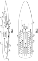
Figure 2 is is a schematic view of a bottom surface of an example aircraft structure including a skin heat exchanger assembly. -
Figure 3 is an enlarged view of a portion of an example skin heat exchanger assembly. -
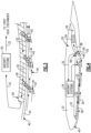
Figure 4 is a schematic view of another example aircraft heat exchanger system. -
Figure 5 is a schematic view of another example aircraft heat exchanger system. -
Figure 1 is a schematic view of an example aircraftheat exchanger system 20 disposed in anaircraft structure 22. Theaircraft structure 22 may be the aircraft fuselage, a wing or other lifting structure. The disclosedexample aircraft structure 22 includes an imbeddedpropulsor assembly 34 that receives air flow through aninlet duct 38. Thepropulsor assembly 34 creates a high energy propulsive flow that is exhausted through anexhaust duct 36. In one disclosed example, thepropulsor assembly 34 is electrically powered In another disclosed example embodiment, thepropulsor assembly 34 is a hybrid system that combines conventional combustion with electric power. It should be understood that although several types of propulsor assemblies are disclosed by way of example that any propulsor assembly would benefit from the heat exchanger system of this disclosure and are within the contemplation of this disclosure. - The
inlet duct 38 is sized to provide a desired amount of airflow to thepropulsor assembly 34. The size over theinlet duct 38 is constrained by the size and shape of theaircraft structure 22. Accordingly, exposure to inlet airflow is limited by the size of theinlet duct 38. The constrained amount of airflow may limit a thermal capacity of a heat exchanger system required to cool and transfer heat produced byvarious aircraft systems 24. Theaircraft systems 24 are shown schematically and may include lubricant, cooled cooling air, buffer cooling air and any other aircraft systems that transfer thermal energy to operate efficiently. A disclosed example heat exchanger system embodiment provides for increased thermal transfer capacity without modifications to theinlet duct 38. - The example
heat exchanger system 20 includes a firstheat exchanger assembly 26 that is disposed in theinlet duct 38 and in thermal communication with anairflow 30 such that someairflow portion 35 is ingested intoinlet duct 38. A skinheat exchanger assembly 28 is disposed along anouter bottom surface 40 of theaircraft structure 22 and in thermal communication with theairflow 30. The firstheat exchanger assembly 26 and the skinheat exchanger assembly 28 are in fluid communication such that a workingfluid 32 flows between the firstheat exchanger assembly 26 and theskin heat exchanger 28. The workingfluid 32 may include lubricant, fuel, hydraulic fluid as well as other flows that require thermal transfer of heat for efficient operation. - In one disclosed example, a working
fluid 32 is communicated first through the firstheat exchanger assembly 26. The firstheat exchanger assembly 26 transfers some quantity of thermal energy into theingest airflow 35. The amount of thermal energy transferred may be sufficient to provide efficient operation. However, should additional thermal energy transfer be required, the workingfluid 32 may be communicated to the skinheat exchanger assembly 26. In one disclosed example, thefirst heat exchanger 26 provides between 80% and 100% of the required thermal transfer capacity desired to sufficiently cool the workingfluid 32 and the skin heat exchanger assembly provides the remaining thermal transfer capacity. In another disclosed embodiment, thefirst heat exchanger 26 provides between 85% and 90% of the required thermal transfer capacity and the skin heat exchanger assembly provides the remaining 15% to 10%. As appreciated, other combinations of heat transfer capacity may be utilized and are within the contemplation of this disclosure. - Referring to
Figures 2 and3 with continued reference toFigure 1 , the exampleheat transfer system 20 includes theskin heat exchanger 28 disposed on a bottom surface of theaircraft structure 22. Theskin heat exchanger 28 may have any shape, width and length that provides a desired thermal transfer capacity. Thebottom surface 40 is typically not exposed to sunlight for extended periods of time and therefore is where the exampleskin heat exchanger 28 is mounted. - In this disclosed example, the
skin heat exchanger 28 is disposed on either side of theinlet 38. The offset placement of theskin heat exchanger 28 provides for non-heatedboundary layer airflow 35 to be communicated into theinlet 38. Accordingly, airflow that has accepted heat through contact with theskin heat exchanger 28 is not substantially communicated into theinlet 38. Theinlet 38 and thereby thefirst heat exchanger 26 is not provided with preheated air. It should be appreciated that it is within the contemplation and scope of this disclosure that theskin heat exchanger 28 may be located in other portions of theaircraft structure 22 that do not result in preheated air being communicated into theinlet 38. - Moreover, the thermal transfer of heat through the skin 44 provided by the disclosed
skin heat exchanger 28 may be utilized to provide additional functions that make use of the communicated thermal energy. In one disclosed example, theskin heat exchanger 28 may provide anti-icing functions to prevent ice build up on portions of theaircraft structure 22. Theskin heat exchanger 28 may be located, at least partially, on a leading edge of a wing or other lift generating structure of theaircraft structure 22 to provide an anti-icing function. Moreover, other beneficial uses of the thermal energy transferred through the skin 44 may be utilized by providing a specific location of theskin heat exchanger 28 and are within the scope and contemplation of this disclosure. - The
skin heat exchanger 28 is placed in direct thermal transfer contact with a skin 44 of theaircraft structure 22. The direct contact with the skin 44 provides for thermal contact with theboundary layer flow 30 generated during aircraft operation. The workingfluid 32 is flowed through theskin heat exchanger 28 in a forward direction that opposes theboundary layer flow 30. Stated another way, the workingfluid 32 is flowed from an aft position toward a forward location that is opposite theflow 30 along the outer skin 44. Thermal energy illustrated byarrows 42 is transferred into theflow 30 and the cooled workingfluid 32 is communicated back to thecorresponding aircraft system 24. - The
skin heat exchanger 28 may be configured with multiple channels and passages for the workingfluid 32 that are placed in thermal communication with the skin 44 and thereby theflow 30. It should be appreciated, that theskin heat exchanger 28 may be constructed of any applicable, known, thermal transfer materials and structures and all such materials and configurations are within the contemplation and scope of this disclosure. - The disclosed example
skin heat exchanger 28 is black to provide the advantageous thermal absorption properties associated with black body radiation. In this disclosed example, the black body of the skin heat exchanger is schematically indicated at 50. - Moreover, the
skin heat exchanger 28 provides the increased thermal transfer capacity without introducing any additional aerodynamic drag. Furthermore, the skin heat exchanger is advantageous for cooling workingfluids 32 that operate most efficiently when brought to ambient temperatures due to the large surface areas and high convective cooling rates during aircraft operation. - Referring to
Figure 4 , the exampleheat exchange system 20 is shown with the workingfluid 32 first being communicated to aninlet 46 of the skinheat exchanger assembly 28. The workingfluid 32 is communicated forward and then back to the firstheat exchanger assembly 26 disposed in theinlet duct 38. Accordingly, in this disclosed embodiment, the workingfluid 32 is initially cooled and then cooled completely by the firstheat exchanger assembly 26. The different configurations of workingfluid flow 32 are possible to combine the thermal transfer capacities of the firstheat exchanger assembly 26 and the skinheat exchanger assembly 28. As appreciated, other routing and communication of the working fluid between the firstheat exchanger assembly 26 and the skinheat exchanger assembly 28 are possible and within the scope and contemplation of this disclosure. - Referring to
Figure 5 , anotherheat exchanger system 52 is schematically shown and includes asecond heat exchanger 54. Thesecond heat exchanger 54 is in thermal communication with another coolingflow 56 and with the workingfluid 32. The secondheat exchanger assembly 54 may include a single heat exchanger or multiple heat exchangers that are utilized to further transfer thermal energy. In this disclosed example, the workingfluid 32 is communicated from theaircraft systems 24 to thesecond heat exchanger 54 where it is cooled by the coolingflow 56. The workingfluid 32 is then communicated to aninlet 48 of thefirst heat exchanger 26 for additional transfer of thermal energy. The workingfluid 32 is then routed toinlet 46 for further thermal transfer by theskin heat exchanger 28. As appreciated, routing of the workingfluid 32 may be controlled by various valves and conduits to select some combination of the heat exchangers required to transfer thermal energy as desired. - Accordingly, the disclosed example heat exchanger systems provide for increased thermal efficiencies within the size constraint arising from alternate propulsor mounting and limited inlet duct size. Additionally, disclosed heat exchanger system embodiments provide for use of smaller heat exchangers in engine inlet ducts while the skin
heat exchanger assembly 28 does not increase drag and thereby further provides for increased engine efficiencies. - Although an example embodiment has been disclosed, a worker of ordinary skill in this art would recognize that certain modifications would come within the scope of this disclosure. For that reason, the following claims should be studied to determine the scope and content of this disclosure.
Claims (13)
- An aircraft heat exchanger system (20) comprising:a first heat exchanger assembly (26) disposed in an inlet duct assembly (38); anda skin heat exchanger assembly (28) in thermal communication with an outer surface (40) of an aircraft structure (22), the skin heat exchanger (28) in fluid communication with the first heat exchanger (26) such that a working fluid (32) is communicated therebetween.
- An aircraft propulsion system comprising:a propulsor assembly (34) disposed in an aircraft structure (22);an inlet duct (38) for communicating airflow to the propulsor assembly (34), the inlet duct (38) disposed in the aircraft structure (22);a first heat exchanger assembly (26) disposed in the inlet duct assembly (38) and in thermal transfer communication with airflow through the inlet duct (38); anda skin heat exchanger assembly (28) in thermal communication with an outer surface (40) of the aircraft structure (22).
- The aircraft propulsion system as recited in claim 2, wherein the skin heat exchanger assembly (28) is in fluid communication with the first heat exchanger (26) such that a working fluid (32) is communicated therebetween.
- The heat exchanger system (20) or aircraft propulsion system as recited in any of claims 1 to 3, wherein the skin heat exchanger (28) is disposed along a bottom surface (40) of the aircraft structure (22).
- The heat exchanger system (20) or aircraft propulsion system as recited in any of claims 1 to 3, wherein the outer surface (40) of the aircraft structure (22) comprises a bottom facing surface of the aircraft structure (22).
- The heat exchanger system (20) or aircraft propulsion system as recited in any preceding claim, wherein an aircraft skin (44) is communication with a boundary layer flow of air.
- The heat exchanger system (20) or aircraft propulsion system as recited in any preceding claim, wherein the first heat exchanger assembly (26) includes a first outlet that communicates the working flow (32) to an inlet of the skin heat exchanger (28).
- The heat exchanger system (20) or aircraft propulsion system as recited in any preceding claim, wherein the skin heat exchanger (28) includes a second outlet that communicates the working flow (32) to the first heat exchanger assembly (26).
- The heat exchanger system (20) or aircraft propulsion system as recited in any preceding claim, wherein the outer surface (40) of the aircraft structure (22) comprises a bottom facing surface of the aircraft structure (22).
- The heat exchanger system (20) or aircraft propulsion system as recited in any preceding claim, wherein the skin heat exchanger assembly (28) is black.
- The heat exchanger system (52) or aircraft propulsion system as recited in any preceding claim, including a second heat exchanger assembly (54) disposed in the aircraft structure (22), the second heat exchanger (54) in fluid communication with the skin heat exchanger assembly (28).
- The heat exchanger system (20) or aircraft propulsion system as recited in any preceding claim, wherein the aircraft structure (22) comprises at least one of an aircraft fuselage or an aircraft wing.
- A method of transferring thermal energy from an aircraft system working fluid (32), the method comprising:transferring a first quantity of thermal energy with a first heat exchanger (26) exposed to an inlet airflow (35) through an air inlet (38) of a propulsion system; andtransferring a second quantity of thermal energy with a skin heat exchanger (28) exposed to a boundary layer airflow along a surface (40) of an aircraft structure (22).
Priority Applications (1)
| Application Number | Priority Date | Filing Date | Title |
|---|---|---|---|
| EP25186799.0A EP4603390A3 (en) | 2022-01-26 | 2023-01-23 | Aircraft skin heat exchanger |
Applications Claiming Priority (1)
| Application Number | Priority Date | Filing Date | Title |
|---|---|---|---|
| US17/584,909 US11891953B2 (en) | 2022-01-26 | 2022-01-26 | Aircraft skin heat exchanger |
Related Child Applications (1)
| Application Number | Title | Priority Date | Filing Date |
|---|---|---|---|
| EP25186799.0A Division EP4603390A3 (en) | 2022-01-26 | 2023-01-23 | Aircraft skin heat exchanger |
Publications (2)
| Publication Number | Publication Date |
|---|---|
| EP4219315A1 true EP4219315A1 (en) | 2023-08-02 |
| EP4219315B1 EP4219315B1 (en) | 2025-07-02 |
Family
ID=85036363
Family Applications (2)
| Application Number | Title | Priority Date | Filing Date |
|---|---|---|---|
| EP25186799.0A Pending EP4603390A3 (en) | 2022-01-26 | 2023-01-23 | Aircraft skin heat exchanger |
| EP23152943.9A Active EP4219315B1 (en) | 2022-01-26 | 2023-01-23 | Aircraft skin heat exchanger |
Family Applications Before (1)
| Application Number | Title | Priority Date | Filing Date |
|---|---|---|---|
| EP25186799.0A Pending EP4603390A3 (en) | 2022-01-26 | 2023-01-23 | Aircraft skin heat exchanger |
Country Status (2)
| Country | Link |
|---|---|
| US (1) | US11891953B2 (en) |
| EP (2) | EP4603390A3 (en) |
Families Citing this family (1)
| Publication number | Priority date | Publication date | Assignee | Title |
|---|---|---|---|---|
| EP4286279B1 (en) * | 2022-05-13 | 2025-07-02 | Airbus S.A.S. | Structural cooling system for an aircraft |
Citations (5)
| Publication number | Priority date | Publication date | Assignee | Title |
|---|---|---|---|---|
| US20170036775A1 (en) * | 2015-08-07 | 2017-02-09 | Pratt & Whitney Canada Corp. | Aircraft heating assembly with liquid cooled internal combustion engine and heating element using waste heat |
| US20170167382A1 (en) * | 2015-12-09 | 2017-06-15 | General Electric Company | Thermal Management System |
| US20180051716A1 (en) * | 2016-08-19 | 2018-02-22 | General Electric Company | Thermal management system for an electric propulsion engine |
| GB2581795A (en) * | 2019-02-26 | 2020-09-02 | Bae Systems Plc | Thermal management system |
| WO2021032476A1 (en) * | 2019-08-21 | 2021-02-25 | Airbus Operations Gmbh | Primary structural assembly for an aircraft outside-skin heat exchanger, aircraft having a primary structural assembly, and method for attaching an aircraft outside-skin heat exchanger |
Family Cites Families (4)
| Publication number | Priority date | Publication date | Assignee | Title |
|---|---|---|---|---|
| US20030029607A1 (en) * | 2001-08-10 | 2003-02-13 | Otter James William | Black layer coated heat exchanger |
| DE102008026536A1 (en) | 2008-06-03 | 2009-12-17 | Airbus Deutschland Gmbh | System and method for cooling a heat-fogged device in a vehicle, in particular an aircraft |
| DE102008035823A1 (en) | 2008-07-31 | 2010-02-25 | Airbus Deutschland Gmbh | Heat exchanger for the outer skin of an aircraft |
| DE102010051517A1 (en) | 2010-11-16 | 2012-05-16 | Airbus Operations Gmbh | An aircraft exterior skin heat exchanger, aircraft cooling system, and method of operating an aircraft exterior skin heat exchanger |
-
2022
- 2022-01-26 US US17/584,909 patent/US11891953B2/en active Active
-
2023
- 2023-01-23 EP EP25186799.0A patent/EP4603390A3/en active Pending
- 2023-01-23 EP EP23152943.9A patent/EP4219315B1/en active Active
Patent Citations (5)
| Publication number | Priority date | Publication date | Assignee | Title |
|---|---|---|---|---|
| US20170036775A1 (en) * | 2015-08-07 | 2017-02-09 | Pratt & Whitney Canada Corp. | Aircraft heating assembly with liquid cooled internal combustion engine and heating element using waste heat |
| US20170167382A1 (en) * | 2015-12-09 | 2017-06-15 | General Electric Company | Thermal Management System |
| US20180051716A1 (en) * | 2016-08-19 | 2018-02-22 | General Electric Company | Thermal management system for an electric propulsion engine |
| GB2581795A (en) * | 2019-02-26 | 2020-09-02 | Bae Systems Plc | Thermal management system |
| WO2021032476A1 (en) * | 2019-08-21 | 2021-02-25 | Airbus Operations Gmbh | Primary structural assembly for an aircraft outside-skin heat exchanger, aircraft having a primary structural assembly, and method for attaching an aircraft outside-skin heat exchanger |
Also Published As
| Publication number | Publication date |
|---|---|
| EP4219315B1 (en) | 2025-07-02 |
| US20230235699A1 (en) | 2023-07-27 |
| EP4603390A2 (en) | 2025-08-20 |
| EP4603390A3 (en) | 2025-10-15 |
| US11891953B2 (en) | 2024-02-06 |
Similar Documents
| Publication | Publication Date | Title |
|---|---|---|
| EP3931093B1 (en) | Aircraft having hybrid-electric propulsion system with electric storage located in fuselage | |
| US11807371B2 (en) | Aircraft having hybrid-electric propulsion system with electric storage located in fuselage | |
| CN101903245B (en) | Aircraft with aircraft cooling system | |
| EP3931095A2 (en) | Aircraft having hybrid-electric propulsion system with electric storage located in wings | |
| EP3666570B1 (en) | Battery thermal management system for a vehicle | |
| US11174816B2 (en) | Bypass duct conformal heat exchanger array | |
| CN113914945A (en) | Thermal management system | |
| EP2500270B1 (en) | Aircraft capable of hovering | |
| EP4286279B1 (en) | Structural cooling system for an aircraft | |
| US20230074603A1 (en) | Aircraft propeller blade radiator | |
| US20200239152A1 (en) | Thermal management system | |
| EP3931099B1 (en) | Cooling system configurations for an aircraft having hybrid-electric propulsion system | |
| EP4219315B1 (en) | Aircraft skin heat exchanger | |
| KR20250025584A (en) | Fuel cell aircraft thermal management system | |
| CN118083141A (en) | Heat dissipation structure and heat dissipation method of aviation hybrid electric propulsion system | |
| US20100326049A1 (en) | Cooling systems for rotorcraft engines | |
| EP3981688A1 (en) | Air cooling | |
| KR20250025585A (en) | Low temperature proton exchange membrane charge air heat exchanger | |
| CN120077496A (en) | Aircraft with fuel cell propulsion system | |
| EP3715603B1 (en) | Fuel heat exchanger with a barrier | |
| EP4219316B1 (en) | Off-set duct heat exchanger | |
| US20260125160A1 (en) | Wing cooling system for fuel cell | |
| KR102732661B1 (en) | Flight vehicle | |
| US20260081554A1 (en) | Thermophotovoltaic (tpv) power generator | |
| KR20250025583A (en) | Start-up of high temperature proton exchange membrane (htpem) fuel cell aircraft with multiple power generating units |
Legal Events
| Date | Code | Title | Description |
|---|---|---|---|
| PUAI | Public reference made under article 153(3) epc to a published international application that has entered the european phase |
Free format text: ORIGINAL CODE: 0009012 |
|
| STAA | Information on the status of an ep patent application or granted ep patent |
Free format text: STATUS: THE APPLICATION HAS BEEN PUBLISHED |
|
| AK | Designated contracting states |
Kind code of ref document: A1 Designated state(s): AL AT BE BG CH CY CZ DE DK EE ES FI FR GB GR HR HU IE IS IT LI LT LU LV MC ME MK MT NL NO PL PT RO RS SE SI SK SM TR |
|
| RAP3 | Party data changed (applicant data changed or rights of an application transferred) |
Owner name: RTX CORPORATION |
|
| STAA | Information on the status of an ep patent application or granted ep patent |
Free format text: STATUS: REQUEST FOR EXAMINATION WAS MADE |
|
| 17P | Request for examination filed |
Effective date: 20240202 |
|
| RBV | Designated contracting states (corrected) |
Designated state(s): AL AT BE BG CH CY CZ DE DK EE ES FI FR GB GR HR HU IE IS IT LI LT LU LV MC ME MK MT NL NO PL PT RO RS SE SI SK SM TR |
|
| GRAP | Despatch of communication of intention to grant a patent |
Free format text: ORIGINAL CODE: EPIDOSNIGR1 |
|
| STAA | Information on the status of an ep patent application or granted ep patent |
Free format text: STATUS: GRANT OF PATENT IS INTENDED |
|
| RIC1 | Information provided on ipc code assigned before grant |
Ipc: B64D 15/02 20060101ALN20241220BHEP Ipc: B64D 33/02 20060101ALN20241220BHEP Ipc: B64C 3/26 20060101ALN20241220BHEP Ipc: B64C 1/12 20060101ALN20241220BHEP Ipc: B64D 33/10 20060101AFI20241220BHEP |
|
| INTG | Intention to grant announced |
Effective date: 20250128 |
|
| GRAS | Grant fee paid |
Free format text: ORIGINAL CODE: EPIDOSNIGR3 |
|
| GRAA | (expected) grant |
Free format text: ORIGINAL CODE: 0009210 |
|
| STAA | Information on the status of an ep patent application or granted ep patent |
Free format text: STATUS: THE PATENT HAS BEEN GRANTED |
|
| AK | Designated contracting states |
Kind code of ref document: B1 Designated state(s): AL AT BE BG CH CY CZ DE DK EE ES FI FR GB GR HR HU IE IS IT LI LT LU LV MC ME MK MT NL NO PL PT RO RS SE SI SK SM TR |
|
| REG | Reference to a national code |
Ref country code: GB Ref legal event code: FG4D |
|
| REG | Reference to a national code |
Ref country code: CH Ref legal event code: EP |
|
| REG | Reference to a national code |
Ref country code: DE Ref legal event code: R096 Ref document number: 602023004367 Country of ref document: DE |
|
| REG | Reference to a national code |
Ref country code: IE Ref legal event code: FG4D |
|
| REG | Reference to a national code |
Ref country code: NL Ref legal event code: MP Effective date: 20250702 |
|
| PG25 | Lapsed in a contracting state [announced via postgrant information from national office to epo] |
Ref country code: PT Free format text: LAPSE BECAUSE OF FAILURE TO SUBMIT A TRANSLATION OF THE DESCRIPTION OR TO PAY THE FEE WITHIN THE PRESCRIBED TIME-LIMIT Effective date: 20251103 |
|
| PG25 | Lapsed in a contracting state [announced via postgrant information from national office to epo] |
Ref country code: NL Free format text: LAPSE BECAUSE OF FAILURE TO SUBMIT A TRANSLATION OF THE DESCRIPTION OR TO PAY THE FEE WITHIN THE PRESCRIBED TIME-LIMIT Effective date: 20250702 |
|
| REG | Reference to a national code |
Ref country code: AT Ref legal event code: MK05 Ref document number: 1808998 Country of ref document: AT Kind code of ref document: T Effective date: 20250702 |
|
| PG25 | Lapsed in a contracting state [announced via postgrant information from national office to epo] |
Ref country code: IS Free format text: LAPSE BECAUSE OF FAILURE TO SUBMIT A TRANSLATION OF THE DESCRIPTION OR TO PAY THE FEE WITHIN THE PRESCRIBED TIME-LIMIT Effective date: 20251102 |
|
| PG25 | Lapsed in a contracting state [announced via postgrant information from national office to epo] |
Ref country code: NO Free format text: LAPSE BECAUSE OF FAILURE TO SUBMIT A TRANSLATION OF THE DESCRIPTION OR TO PAY THE FEE WITHIN THE PRESCRIBED TIME-LIMIT Effective date: 20251002 |
|
| REG | Reference to a national code |
Ref country code: LT Ref legal event code: MG9D |
|
| PG25 | Lapsed in a contracting state [announced via postgrant information from national office to epo] |
Ref country code: AT Free format text: LAPSE BECAUSE OF FAILURE TO SUBMIT A TRANSLATION OF THE DESCRIPTION OR TO PAY THE FEE WITHIN THE PRESCRIBED TIME-LIMIT Effective date: 20250702 |
|
| PG25 | Lapsed in a contracting state [announced via postgrant information from national office to epo] |
Ref country code: FI Free format text: LAPSE BECAUSE OF FAILURE TO SUBMIT A TRANSLATION OF THE DESCRIPTION OR TO PAY THE FEE WITHIN THE PRESCRIBED TIME-LIMIT Effective date: 20250702 |
|
| PG25 | Lapsed in a contracting state [announced via postgrant information from national office to epo] |
Ref country code: HR Free format text: LAPSE BECAUSE OF FAILURE TO SUBMIT A TRANSLATION OF THE DESCRIPTION OR TO PAY THE FEE WITHIN THE PRESCRIBED TIME-LIMIT Effective date: 20250702 |
|
| PGFP | Annual fee paid to national office [announced via postgrant information from national office to epo] |
Ref country code: FR Payment date: 20251217 Year of fee payment: 4 |
|
| PG25 | Lapsed in a contracting state [announced via postgrant information from national office to epo] |
Ref country code: GR Free format text: LAPSE BECAUSE OF FAILURE TO SUBMIT A TRANSLATION OF THE DESCRIPTION OR TO PAY THE FEE WITHIN THE PRESCRIBED TIME-LIMIT Effective date: 20251003 |
|
| PG25 | Lapsed in a contracting state [announced via postgrant information from national office to epo] |
Ref country code: SE Free format text: LAPSE BECAUSE OF FAILURE TO SUBMIT A TRANSLATION OF THE DESCRIPTION OR TO PAY THE FEE WITHIN THE PRESCRIBED TIME-LIMIT Effective date: 20250702 Ref country code: CZ Free format text: LAPSE BECAUSE OF FAILURE TO SUBMIT A TRANSLATION OF THE DESCRIPTION OR TO PAY THE FEE WITHIN THE PRESCRIBED TIME-LIMIT Effective date: 20250702 |
|
| PG25 | Lapsed in a contracting state [announced via postgrant information from national office to epo] |
Ref country code: LV Free format text: LAPSE BECAUSE OF FAILURE TO SUBMIT A TRANSLATION OF THE DESCRIPTION OR TO PAY THE FEE WITHIN THE PRESCRIBED TIME-LIMIT Effective date: 20250702 |
|
| PG25 | Lapsed in a contracting state [announced via postgrant information from national office to epo] |
Ref country code: BG Free format text: LAPSE BECAUSE OF FAILURE TO SUBMIT A TRANSLATION OF THE DESCRIPTION OR TO PAY THE FEE WITHIN THE PRESCRIBED TIME-LIMIT Effective date: 20250702 Ref country code: PL Free format text: LAPSE BECAUSE OF FAILURE TO SUBMIT A TRANSLATION OF THE DESCRIPTION OR TO PAY THE FEE WITHIN THE PRESCRIBED TIME-LIMIT Effective date: 20250702 |
|
| PG25 | Lapsed in a contracting state [announced via postgrant information from national office to epo] |
Ref country code: RS Free format text: LAPSE BECAUSE OF FAILURE TO SUBMIT A TRANSLATION OF THE DESCRIPTION OR TO PAY THE FEE WITHIN THE PRESCRIBED TIME-LIMIT Effective date: 20251002 |
|
| PG25 | Lapsed in a contracting state [announced via postgrant information from national office to epo] |
Ref country code: ES Free format text: LAPSE BECAUSE OF FAILURE TO SUBMIT A TRANSLATION OF THE DESCRIPTION OR TO PAY THE FEE WITHIN THE PRESCRIBED TIME-LIMIT Effective date: 20250702 |
|
| PG25 | Lapsed in a contracting state [announced via postgrant information from national office to epo] |
Ref country code: SM Free format text: LAPSE BECAUSE OF FAILURE TO SUBMIT A TRANSLATION OF THE DESCRIPTION OR TO PAY THE FEE WITHIN THE PRESCRIBED TIME-LIMIT Effective date: 20250702 |
|
| PG25 | Lapsed in a contracting state [announced via postgrant information from national office to epo] |
Ref country code: DK Free format text: LAPSE BECAUSE OF FAILURE TO SUBMIT A TRANSLATION OF THE DESCRIPTION OR TO PAY THE FEE WITHIN THE PRESCRIBED TIME-LIMIT Effective date: 20250702 |
|
| PGFP | Annual fee paid to national office [announced via postgrant information from national office to epo] |
Ref country code: DE Payment date: 20251217 Year of fee payment: 4 |
|
| PG25 | Lapsed in a contracting state [announced via postgrant information from national office to epo] |
Ref country code: IT Free format text: LAPSE BECAUSE OF FAILURE TO SUBMIT A TRANSLATION OF THE DESCRIPTION OR TO PAY THE FEE WITHIN THE PRESCRIBED TIME-LIMIT Effective date: 20250702 |
|
| PG25 | Lapsed in a contracting state [announced via postgrant information from national office to epo] |
Ref country code: SK Free format text: LAPSE BECAUSE OF FAILURE TO SUBMIT A TRANSLATION OF THE DESCRIPTION OR TO PAY THE FEE WITHIN THE PRESCRIBED TIME-LIMIT Effective date: 20250702 Ref country code: EE Free format text: LAPSE BECAUSE OF FAILURE TO SUBMIT A TRANSLATION OF THE DESCRIPTION OR TO PAY THE FEE WITHIN THE PRESCRIBED TIME-LIMIT Effective date: 20250702 |
|
| PLBE | No opposition filed within time limit |
Free format text: ORIGINAL CODE: 0009261 |
|
| STAA | Information on the status of an ep patent application or granted ep patent |
Free format text: STATUS: NO OPPOSITION FILED WITHIN TIME LIMIT |