EP4219313A1 - Autothrottle control for turboprop engines - Google Patents
Autothrottle control for turboprop engines Download PDFInfo
- Publication number
- EP4219313A1 EP4219313A1 EP23164482.4A EP23164482A EP4219313A1 EP 4219313 A1 EP4219313 A1 EP 4219313A1 EP 23164482 A EP23164482 A EP 23164482A EP 4219313 A1 EP4219313 A1 EP 4219313A1
- Authority
- EP
- European Patent Office
- Prior art keywords
- power
- engine
- thrust
- aircraft
- powerplant
- Prior art date
- Legal status (The legal status is an assumption and is not a legal conclusion. Google has not performed a legal analysis and makes no representation as to the accuracy of the status listed.)
- Granted
Links
Images


Classifications
-
- B—PERFORMING OPERATIONS; TRANSPORTING
- B64—AIRCRAFT; AVIATION; COSMONAUTICS
- B64D—EQUIPMENT FOR FITTING IN OR TO AIRCRAFT; FLIGHT SUITS; PARACHUTES; ARRANGEMENT OR MOUNTING OF POWER PLANTS OR PROPULSION TRANSMISSIONS IN AIRCRAFT
- B64D31/00—Power plant control systems; Arrangement of power plant control systems in aircraft
- B64D31/02—Initiating means
- B64D31/06—Initiating means actuated automatically
-
- B—PERFORMING OPERATIONS; TRANSPORTING
- B64—AIRCRAFT; AVIATION; COSMONAUTICS
- B64C—AEROPLANES; HELICOPTERS
- B64C11/00—Propellers, e.g. of ducted type; Features common to propellers and rotors for rotorcraft
- B64C11/30—Blade pitch-changing mechanisms
-
- B—PERFORMING OPERATIONS; TRANSPORTING
- B64—AIRCRAFT; AVIATION; COSMONAUTICS
- B64C—AEROPLANES; HELICOPTERS
- B64C11/00—Propellers, e.g. of ducted type; Features common to propellers and rotors for rotorcraft
- B64C11/30—Blade pitch-changing mechanisms
- B64C11/303—Blade pitch-changing mechanisms characterised by comprising a governor
-
- B—PERFORMING OPERATIONS; TRANSPORTING
- B64—AIRCRAFT; AVIATION; COSMONAUTICS
- B64D—EQUIPMENT FOR FITTING IN OR TO AIRCRAFT; FLIGHT SUITS; PARACHUTES; ARRANGEMENT OR MOUNTING OF POWER PLANTS OR PROPULSION TRANSMISSIONS IN AIRCRAFT
- B64D27/00—Arrangement or mounting of power plants in aircraft; Aircraft characterised by the type or position of power plants
- B64D27/02—Aircraft characterised by the type or position of power plants
- B64D27/10—Aircraft characterised by the type or position of power plants of gas-turbine type
-
- F—MECHANICAL ENGINEERING; LIGHTING; HEATING; WEAPONS; BLASTING
- F02—COMBUSTION ENGINES; HOT-GAS OR COMBUSTION-PRODUCT ENGINE PLANTS
- F02C—GAS-TURBINE PLANTS; AIR INTAKES FOR JET-PROPULSION PLANTS; CONTROLLING FUEL SUPPLY IN AIR-BREATHING JET-PROPULSION PLANTS
- F02C9/00—Controlling gas-turbine plants; Controlling fuel supply in air- breathing jet-propulsion plants
- F02C9/48—Control of fuel supply conjointly with another control of the plant
- F02C9/56—Control of fuel supply conjointly with another control of the plant with power transmission control
- F02C9/58—Control of fuel supply conjointly with another control of the plant with power transmission control with control of a variable-pitch propeller
-
- F—MECHANICAL ENGINEERING; LIGHTING; HEATING; WEAPONS; BLASTING
- F05—INDEXING SCHEMES RELATING TO ENGINES OR PUMPS IN VARIOUS SUBCLASSES OF CLASSES F01-F04
- F05D—INDEXING SCHEME FOR ASPECTS RELATING TO NON-POSITIVE-DISPLACEMENT MACHINES OR ENGINES, GAS-TURBINES OR JET-PROPULSION PLANTS
- F05D2220/00—Application
- F05D2220/30—Application in turbines
- F05D2220/32—Application in turbines in gas turbines
- F05D2220/325—Application in turbines in gas turbines to drive unshrouded, high solidity propeller
-
- F—MECHANICAL ENGINEERING; LIGHTING; HEATING; WEAPONS; BLASTING
- F05—INDEXING SCHEMES RELATING TO ENGINES OR PUMPS IN VARIOUS SUBCLASSES OF CLASSES F01-F04
- F05D—INDEXING SCHEME FOR ASPECTS RELATING TO NON-POSITIVE-DISPLACEMENT MACHINES OR ENGINES, GAS-TURBINES OR JET-PROPULSION PLANTS
- F05D2270/00—Control
- F05D2270/01—Purpose of the control system
- F05D2270/05—Purpose of the control system to affect the output of the engine
- F05D2270/051—Thrust
-
- F—MECHANICAL ENGINEERING; LIGHTING; HEATING; WEAPONS; BLASTING
- F05—INDEXING SCHEMES RELATING TO ENGINES OR PUMPS IN VARIOUS SUBCLASSES OF CLASSES F01-F04
- F05D—INDEXING SCHEME FOR ASPECTS RELATING TO NON-POSITIVE-DISPLACEMENT MACHINES OR ENGINES, GAS-TURBINES OR JET-PROPULSION PLANTS
- F05D2270/00—Control
- F05D2270/01—Purpose of the control system
- F05D2270/12—Purpose of the control system to maintain desired vehicle trajectory parameters
- F05D2270/122—Speed or Mach number
Definitions
- the disclosure relates generally to the integration of an autothrottle function into a propeller-driven aircraft between the aircraft systems and the powerplant systems (i.e. engine and propeller).
- Modern large commuter turbofan-powered aircraft incorporate a high level of automation in regards to flight management. This includes autopilot, flight director, and autothrust systems. Similar systems exist in high-end business jet aircraft.
- a method for controlling a propeller-driven aircraft powered by at least one gas turbine engine comprises obtaining a thrust change corresponding to a difference between an actual thrust of the at least one engine and a desired thrust for the at least one engine.
- a setting change to at least one control input of the at least one engine is determined.
- At least one command is output to cause the setting change of the at least one control input.
- the method may further comprise converting the thrust change into an engine power value and determining the setting change as a function of the engine power value.
- the at least one control input may be for a power throttle associated with the at least one engine.
- Outputting at least one command may comprise outputting at least one of a power lever angle command and a power lever angle trim command.
- the power lever angle command and the power lever angle trim command may be dependent on a mode of operation of the aircraft.
- the at least one control input may correspond to at least one of an engine fuel flow and a propeller pitch angle for the at least one engine.
- Obtaining the thrust change may comprise: determining the actual thrust from a measured engine output power and a measured propeller speed; and determining the desired thrust from a requested engine power and a reference propeller governing speed.
- Obtaining the thrust change may comprise receiving at least one aircraft operating condition and using the at least one aircraft operating condition to determine the actual thrust.
- Outputting at least one command may comprise transmitting the at least one command from aircraft avionics to an engine controller for the at least one engine.
- an autothrottle system for at least one gas turbine engine of a propeller-driven aircraft.
- the system comprises a processing unit and a non-transitory computer-readable memory having stored thereon program instructions.
- the program instructions are executable by the processing unit for obtaining a thrust change corresponding to a difference between an actual thrust of the at least one engine and a desired thrust for the at least one engine.
- a thrust change is greater than a threshold, a setting change to at least one control input of the at least one engine is determined and at least one command is output to cause the setting change of the at least one control input.
- the program instructions may be further executable for converting the thrust change into an engine power value and determining the setting change as a function of the engine power value.
- the at least one control input may be for a power throttle associated with the at least one engine.
- Outputting at least one command may comprise outputting at least one of a power lever angle command and a power lever angle trim command.
- the power lever angle command and the power lever angle trim command may be dependent on a mode of operation of the aircraft.
- the at least one control input may correspond to at least one of an engine fuel flow and a propeller pitch angle for the at least one engine.
- Obtaining the thrust change may comprise: determining the actual thrust from a measured engine output power and a measured propeller speed; and determining the desired thrust from a requested engine power and a reference propeller governing speed.
- Obtaining the thrust change may comprise receiving at least one aircraft operating condition and using the at least one aircraft operating condition to determine the actual thrust.
- Outputting at least one command may comprise transmitting the at least one command from aircraft avionics to an engine controller for the at least one engine.
- a computer readable medium having stored thereon program code for controlling a propeller-driven aircraft powered by at least one gas turbine engine.
- the program code comprises instructions executable by a process for obtaining a thrust change corresponding to a difference between an actual thrust of the at least one engine and a desired thrust for the at least one engine.
- a thrust change is greater than a threshold, a setting change to at least one control input of the at least one engine is determined and at least one command is output to cause the setting change of the at least one control input.
- the program code may further comprise instructions executable by a processor for converting the thrust change into an engine power value and determining the setting change as a function of the engine power value
- a powerplant 100 for a propeller-driven aircraft generally comprising an engine 110 and a propeller 120.
- the propeller 120 converts rotary motion from a shaft of the engine 110 to provide propulsive force, i.e. thrust, for the aircraft.
- the thrust generated by the powerplant 100 can be broken down into two contributors: the propeller thrust (FNP) and the engine jet thrust (FENJ).
- FNP propeller thrust
- FENJ engine jet thrust
- the propeller thrust is a function of many factors, such as ambient temperature, ambient pressure/altitude, airspeed, propeller rotational speed, and power input to the propeller by the engine, and the airfoil design of the propeller blades.
- the powerplant 100 of Figure 1 is a turboprop engine, but it could also be any other type of engine comprising a propeller 120, such as a piston engine, a turboshaft engine, and the like.
- the engine 110 and the propeller 120 are regulated by a pilot or other operator by way of various control inputs.
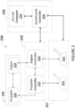
- an example aircraft control system 208 comprising a powerplant control system (PCS) 200.
- the PCS 200 is configured for controlling operation of the powerplant 100, comprising engine 110 and propeller 120.
- An engine controller 210 regulates fuel flow to the engine 110 in order to generate a desired engine output power.
- a propeller controller 220 sets blade pitch angle and/or propeller rotational speed of the propeller 120, so as to convert the engine output power from the engine 110 into thrust.
- a power throttle 201 is controlled by the pilot or other operator in order to provide engine and propeller settings to the powerplant 100 via the PCS 200.
- the power throttle comprises a throttle lever 202 to regulate the output power of the engine 110 and a condition lever 203 to regulate the thrust produced by the propeller 120.
- the power throttle comprises a single lever 202 to control both the engine 110 and the propeller 120.
- An autothrottle controller 204 is operatively connected to the PCS 200 and the power throttle 201.
- the autothrottle controller 204 modulates engine power without pilot input. It may be used, for example, when the aircraft is set to autopilot, but may also be used outside of the autopilot mode.
- the autothrottle controller 204 is integrated into aircraft avionics 206, for example as part of an aircraft computer. Alternatively, the autothrottle controller communicates with the aircraft avionics 206 but is provided externally thereto, such as in the PCS 200 or as another separate component of the aircraft control system 208.
- a required thrust change is obtained.
- the thrust change corresponds to a difference between an actual thrust generated by the powerplant 100 and a desired thrust in accordance with the inputs provided to the powerplant 100.
- the current position of the power throttle 201 also referred to as the power lever angle (PLA)
- PPA power lever angle
- the actual thrust may be determined using a measured engine output power and a measured propeller speed. It should be understood that all thrust determinations are estimated thrust as thrust has no measurement system per se on an aircraft.
- the autothrottle controller 204 receives the thrust change as already determined, for example from an aircraft computer 210.
- the autothrottle controller 204 calculates the thrust change based on various parameters as received from the aircraft computer 210, the PCS 200, the power throttle 201, and/or various sensors on the aircraft and/or powerplant 100.
- the actual thrust is determined from the measured engine output power and the measured propeller speed as received from sensors provided on the engine 110 and/or propeller 120.
- the desired thrust is determined from the requested engine power and the corresponding reference propeller governing speed, as determined from the PLA.
- the autothrottle controller 204 receives the actual thrust and the desired thrust and determines the difference in order to obtain the thrust change.
- the autothrottle controller 204 receives as input one or more aircraft operating condition, such as aircraft speed, ambient temperature, ambient temperature, altitude, and the like.
- ⁇ prop is the propeller efficiency, which is determined by the propeller supplier and may vary as a function of flight phase and speed of the aircraft. Other factors that may affect propeller efficiency are aircraft angle of attack, propeller speed, power, altitude, and ambient temperature. Other factors may also apply. For example, ⁇ prop may be in the order of 60% at takeoff power and typical V1 speed of the aircraft, in the range of 80% to 83% in climb rotational speed and power, and 85% to 87% in cruise rotational speed and power. Other values may also apply, as propeller efficiency is specific to propeller blade design and the design points that the propeller blade has been optimized for.
- the thrust change is converted to a power value.
- a conversion is made to determine what difference in input power is needed to cause the thrust change.
- the power generated by the engine 110 is then converted into thrust by the propeller 120. Therefore in order to speak to the engine 110, the autothrottle controller 204 communicates in terms of power.
- method 300 may be performed without step 304.
- the conversion from thrust to power allows for an easier determination of a setting change at step 306, due to the mapping of engine power and throttle position.
- a setting change is determined for at least one control input of the powerplant 100 when the thrust change or power value is greater than a threshold.
- the setting change corresponds to a change in one or more powerplant input control so as to cause a change in engine power proportional to the thrust change or power value.
- the setting change may cause an increase or a decrease to a currently requested engine power.
- the input control is for the power throttle 201 associated with the PCS 200.
- the input control may be the position of the power throttle, i.e. the PLA.
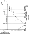
- Figure 4 illustrates an example lookup table 400 for mapping requested engine power to PLA.
- a curve 402 shows a relationship between the PLA (horizontal axis) and the requested power (vertical axis).
- Another curve 450 shows the relationship between the lever angle (horizontal axis) and the reference propeller governing speed (vertical axis).
- the curve 402 is aligned with the curve 450, which share a common horizontal axis, and points on the curve 402 can be mapped with points on the curve 450.
- the power value as converted from the thrust change corresponds to a change in requested power to be applied to the engine.
- a new requested power is found by adding the power value to the current requested power. For example, if the power value is +50 hp and the current requested engine power is 650 hp, then the new requested power used in the table 400 to determine PLA is 700 hp. If the power value is -35 hp and the current requested engine power is 650 hp, then the new requested power used in the table 400 to determine PLA is 615 hp. The corresponding PLA is found on the horizontal axis using the curve 402.
- the input control corresponds to a PLA trim, which is a fine adjustment of the PLA sent to the controller PCS 200 that does not require a physical change in the position of the throttle 202.
- PLA trim is used for small adjustments in commanded power in order to achieve the requested engine power.
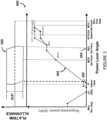
- Figure 5 illustrates an example lookup table 500 for mapping PLA trim to PLA.
- the autothrottle controller 204 may adjust PLA trim only when the PLA is between two defined settings, identified as 502 and 504 on the horizontal axis, for example Flight Idle (FI) and maximum climb (MCL). These settings may be customizable.
- PLA trim may be enabled/disabled by a pilot or other operator through a cockpit command. PLA trim may also be disabled in circumstances where fault accommodation is activated for loss of inputs.
- the input control corresponds to both PLA and PLA trim. In other embodiments, the input control corresponds to engine fuel flow and/or propeller pitch angle. Any control input that affects the amount of power generated by the engine 110 and converted into thrust by the propeller 120 may be varied in accordance with the power value. If the power value is lower than the threshold, the method 300 returns to 302 where a new thrust change is determined.
- At least one command is output by the autothrottle controller 204 to cause the setting change, as per 308.
- the command may be one or more of a PLA command, a PLA trim command, a fuel flow valve command, a propeller speed command, a propeller blade pitch angle command, and the like.
- the autothrottle controller 204 may be configured to output a PLA command directly to a throttle quadrant controller (TQC) comprising a servo-motor and a rotary variable differential transformer (RVDT), which in turn controls the power throttle 201.
- TQC throttle quadrant controller
- RVDT rotary variable differential transformer
- the servo-motor physically moves the power throttle 201 to a given position in accordance with the control command.
- the RVDT sends electrical signals of the throttle position to the engine controller 210.
- a PLA trim command may be sent to the PCS 200, for example to the engine controller 210.
- the use of the PLA trim added to the physical PLA position modulated with servo-motors is to minimize the throttle movement to accommodate for the uncertainties and variability related to the propeller efficiency ⁇ prop determination.
- the autothrottle controller 204 only interfaces with the engine controller 210 and no direct communication is needed with the propeller controller 220.
- the PLA trim is added to the electrical signals sent by RVDT containing the PLA position. The resulting signal is used to determine a power request command to the engine controller 210.
- the PLA setting will also set the propellers to govern at a corresponding reference rotational speed.
- the autothrottle controller 204 is activated by the pilot upon confirmation that the system is capable of operating in an autothrottle mode.
- System capability may be dictated by various conditions. For example, the local throttle position is within specified boundaries, such as flight idle and maximum climb. Local and remote throttles are within a specified tolerance of each other, and the take-off phase of the aircraft is complete and the aircraft is safely in the air.
- certain functionalities are also tested before the system is deemed capable of operating in autothrottle mode, such as the data input interface with the aircraft, the channels of the engine controller 210 (in a multi-channel controller), and the throttle position signal to the engine controller 210.
- the pilot may set aircraft operating targets for autothrottle. These commands are sent from the pilot interface to the autothrottle controller 204. In some embodiments, this is done through the aircraft avionics. Alternatively, the autothrottle controller 204 may be connected directly to the pilot interface. Once operating targets are set, the pilot may enable autothrottle through an autothrottle request signal sent from the pilot interface to the autothrottle controller 204.
- Additional indications provided by the engine controller 210 may be used to dictate whether the autothrottle controller 204 is limited by either an engine limitation or a trim limitation.
- An engine limitation prevents and increase and/or decrease of requested engine power due to a high/low end engine limit being attained.
- a trim limitation prevents and increase and/or decrease of requested engine power due to a high/low end trim limit being attained.
- the PLA trim value is set to a default value of 0° when autothrottle is not enabled or when the system is not capable of operating in an autothrottle mode.
- the PLA trim value is frozen, i.e. held constant to a last value, during propeller reference speed setting changes when the autothrottle is engaged, or if the PLA signal is moving at a rate greater than a predetermined amount.
- the PLA trim value is rate limited to a rate deemed necessary to maintain a smooth aircraft operation when transitioning to/from an engaged to a disengaged autothrottle mode, or when unfrozen following propeller speed reference changes or following the PLA signal moving at rate greater than a predetermined amount.
- the engine controller 210 is implemented as a single-channel or dual-channel full-authority digital engine controls (FADEC), an electronic engine controller (EEC), an engine control unit (ECU), or any other suitable engine controller.
- the propeller controller 220 is implemented as a propeller electronic control (PEC) unit.
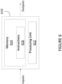
- FIG. 6 illustrates an example embodiment to implement the autothrottle controller 204, so as to perform the method 300.
- a computing device 610 comprises a processing unit 612 and a memory 614 which has stored therein computer-executable instructions 616.
- the processing unit 612 may comprise any suitable devices configured to implement the autothrottle controller 204 such that instructions 616, when executed by the computing device 610 or other programmable apparatus, may cause the functions/acts/steps attributed to the autothrottle controller 204 as described herein to be executed.
- the processing unit 612 may comprise, for example, any type of general-purpose microprocessor or microcontroller, a digital signal processing (DSP) processor, a central processing unit (CPU), an integrated circuit, a field programmable gate array (FPGA), a reconfigurable processor, other suitably programmed or programmable logic circuits, or any combination thereof.
- DSP digital signal processing
- CPU central processing unit
- FPGA field programmable gate array
- reconfigurable processor other suitably programmed or programmable logic circuits, or any combination thereof.
- the memory 614 may comprise any suitable known or other machine-readable storage medium.
- the memory 614 may comprise non-transitory computer readable storage medium, for example, but not limited to, an electronic, magnetic, optical, electromagnetic, infrared, or semiconductor system, apparatus, or device, or any suitable combination of the foregoing.
- the memory 614 may include a suitable combination of any type of computer memory that is located either internally or externally to device, for example random-access memory (RAM), read-only memory (ROM), compact disc read-only memory (CDROM), electro-optical memory, magneto-optical memory, erasable programmable read-only memory (EPROM), and electrically-erasable programmable read-only memory (EEPROM), Ferroelectric RAM (FRAM) or the like.
- Memory 614 may comprise any storage means (e.g., devices) suitable for retrievably storing machine-readable instructions 616 executable by processing unit 612.
- the methods and systems for autothrottle in a propeller-driven aircraft described herein may be implemented in a high level procedural or object oriented programming or scripting language, or a combination thereof, to communicate with or assist in the operation of a computer system, for example the computing device 610.
- the methods and systems for autothrottle in a propeller-driven aircraft may be implemented in assembly or machine language.
- the language may be a compiled or interpreted language.
- Program code for implementing the methods and systems for controlling operation of aircraft engines may be stored on a storage media or a device, for example a ROM, a magnetic disk, an optical disc, a flash drive, or any other suitable storage media or device.
- the program code may be readable by a general or special-purpose programmable computer for configuring and operating the computer when the storage media or device is read by the computer to perform the procedures described herein.
- Embodiments of the methods and systems for autothrottle in a propeller-driven aircraft may also be considered to be implemented by way of a non-transitory computer-readable storage medium having a computer program stored thereon.
- the computer program may comprise computer-readable instructions which cause a computer, or more specifically the processing unit 612 of the computing device 610, to operate in a specific and predefined manner to perform the functions described herein.
- Computer-executable instructions may be in many forms, including program modules, executed by one or more computers or other devices.
- program modules include routines, programs, objects, components, data structures, etc., that perform particular tasks or implement particular abstract data types.
- functionality of the program modules may be combined or distributed as desired in various embodiments.
Landscapes
- Engineering & Computer Science (AREA)
- Aviation & Aerospace Engineering (AREA)
- Chemical & Material Sciences (AREA)
- Combustion & Propulsion (AREA)
- Mechanical Engineering (AREA)
- General Engineering & Computer Science (AREA)
- Combined Controls Of Internal Combustion Engines (AREA)
- Feedback Control In General (AREA)
Abstract
Description
- The disclosure relates generally to the integration of an autothrottle function into a propeller-driven aircraft between the aircraft systems and the powerplant systems (i.e. engine and propeller).
- Modern large commuter turbofan-powered aircraft incorporate a high level of automation in regards to flight management. This includes autopilot, flight director, and autothrust systems. Similar systems exist in high-end business jet aircraft.
- The increased complexity of dealing with the two powerplant components that make up the turboprop powerplant system, namely the engine and the propeller, have made it more difficult to introduce such systems. Therefore, there is a need for improvement.
- In accordance with a first broad aspect, there is provided a method for controlling a propeller-driven aircraft powered by at least one gas turbine engine. The method comprises obtaining a thrust change corresponding to a difference between an actual thrust of the at least one engine and a desired thrust for the at least one engine. When the thrust change is greater than a threshold, a setting change to at least one control input of the at least one engine is determined. At least one command is output to cause the setting change of the at least one control input.
- The method may further comprise converting the thrust change into an engine power value and determining the setting change as a function of the engine power value.
- The at least one control input may be for a power throttle associated with the at least one engine.
- Outputting at least one command may comprise outputting at least one of a power lever angle command and a power lever angle trim command.
- The power lever angle command and the power lever angle trim command may be dependent on a mode of operation of the aircraft.
- The at least one control input may correspond to at least one of an engine fuel flow and a propeller pitch angle for the at least one engine.
- Obtaining the thrust change may comprise: determining the actual thrust from a measured engine output power and a measured propeller speed; and determining the desired thrust from a requested engine power and a reference propeller governing speed.
- Obtaining the thrust change may comprise receiving at least one aircraft operating condition and using the at least one aircraft operating condition to determine the actual thrust.
- Outputting at least one command may comprise transmitting the at least one command from aircraft avionics to an engine controller for the at least one engine.
- In accordance with another broad aspect, there is provided an autothrottle system for at least one gas turbine engine of a propeller-driven aircraft. The system comprises a processing unit and a non-transitory computer-readable memory having stored thereon program instructions. The program instructions are executable by the processing unit for obtaining a thrust change corresponding to a difference between an actual thrust of the at least one engine and a desired thrust for the at least one engine. When the thrust change is greater than a threshold, a setting change to at least one control input of the at least one engine is determined and at least one command is output to cause the setting change of the at least one control input.
- The program instructions may be further executable for converting the thrust change into an engine power value and determining the setting change as a function of the engine power value.
- The at least one control input may be for a power throttle associated with the at least one engine.
- Outputting at least one command may comprise outputting at least one of a power lever angle command and a power lever angle trim command.
- The power lever angle command and the power lever angle trim command may be dependent on a mode of operation of the aircraft.
- The at least one control input may correspond to at least one of an engine fuel flow and a propeller pitch angle for the at least one engine.
- Obtaining the thrust change may comprise: determining the actual thrust from a measured engine output power and a measured propeller speed; and determining the desired thrust from a requested engine power and a reference propeller governing speed.
- Obtaining the thrust change may comprise receiving at least one aircraft operating condition and using the at least one aircraft operating condition to determine the actual thrust.
- Outputting at least one command may comprise transmitting the at least one command from aircraft avionics to an engine controller for the at least one engine.
- In accordance with another broad aspect, there is provided a computer readable medium having stored thereon program code for controlling a propeller-driven aircraft powered by at least one gas turbine engine. The program code comprises instructions executable by a process for obtaining a thrust change corresponding to a difference between an actual thrust of the at least one engine and a desired thrust for the at least one engine. When the thrust change is greater than a threshold, a setting change to at least one control input of the at least one engine is determined and at least one command is output to cause the setting change of the at least one control input.
- The program code may further comprise instructions executable by a processor for converting the thrust change into an engine power value and determining the setting change as a function of the engine power value
- Reference is now made to the accompanying figures in which:
-
Fig. 1 a schematic cross-sectional view of an example powerplant of a propeller-driven aircraft; -
Fig. 2 is a block diagram of an example aircraft control system; -
Fig. 3 is a flowchart of an example method for autothrottle in a propeller-driven aircraft -
Fig. 4 is a graphical representation of an example relationship between requested power/requested propeller governing speed and power lever angle; -
Fig. 5 is a graphical representation of an example relationship between requested power/PLA trim scheduling and power lever angle; and -
Fig. 6 is an example embodiment of an autothrottle controller. - There is described herein systems and methods for an autothrottle system on a propeller-driven aircraft. With reference to
Figure 1 , there is illustrated apowerplant 100 for a propeller-driven aircraft, generally comprising anengine 110 and apropeller 120. Thepropeller 120 converts rotary motion from a shaft of theengine 110 to provide propulsive force, i.e. thrust, for the aircraft. The thrust generated by thepowerplant 100 can be broken down into two contributors: the propeller thrust (FNP) and the engine jet thrust (FENJ). For a turboprop engine, about 95% to 97% of the total thrust is attributable to FNP while 5% to 3% of the total thrust is attributable to FENJ. The propeller thrust is a function of many factors, such as ambient temperature, ambient pressure/altitude, airspeed, propeller rotational speed, and power input to the propeller by the engine, and the airfoil design of the propeller blades. - The
powerplant 100 ofFigure 1 is a turboprop engine, but it could also be any other type of engine comprising apropeller 120, such as a piston engine, a turboshaft engine, and the like. - In regular operation, the
engine 110 and thepropeller 120 are regulated by a pilot or other operator by way of various control inputs. With reference toFigure 2 , there is illustrated an exampleaircraft control system 208 comprising a powerplant control system (PCS) 200. The PCS 200 is configured for controlling operation of thepowerplant 100, comprisingengine 110 andpropeller 120. Anengine controller 210 regulates fuel flow to theengine 110 in order to generate a desired engine output power. Apropeller controller 220 sets blade pitch angle and/or propeller rotational speed of thepropeller 120, so as to convert the engine output power from theengine 110 into thrust. - A
power throttle 201 is controlled by the pilot or other operator in order to provide engine and propeller settings to thepowerplant 100 via the PCS 200. In some embodiments, the power throttle comprises athrottle lever 202 to regulate the output power of theengine 110 and acondition lever 203 to regulate the thrust produced by thepropeller 120. In other embodiments, the power throttle comprises asingle lever 202 to control both theengine 110 and thepropeller 120. - An
autothrottle controller 204 is operatively connected to the PCS 200 and thepower throttle 201. Theautothrottle controller 204 modulates engine power without pilot input. It may be used, for example, when the aircraft is set to autopilot, but may also be used outside of the autopilot mode. In some embodiments, theautothrottle controller 204 is integrated intoaircraft avionics 206, for example as part of an aircraft computer. Alternatively, the autothrottle controller communicates with theaircraft avionics 206 but is provided externally thereto, such as in thePCS 200 or as another separate component of theaircraft control system 208. - Referring to
Figure 3 , there is illustrated a flowchart of anexample method 300 for autothrottle as performed by theautothrottle controller 204. At 302, a required thrust change is obtained. The thrust change corresponds to a difference between an actual thrust generated by thepowerplant 100 and a desired thrust in accordance with the inputs provided to thepowerplant 100. For example, in a single lever configuration, the current position of thepower throttle 201, also referred to as the power lever angle (PLA), will dictate a requested engine power and a corresponding reference propeller governing speed, which may be used to determine the desired thrust. Similarly, the actual thrust may be determined using a measured engine output power and a measured propeller speed. It should be understood that all thrust determinations are estimated thrust as thrust has no measurement system per se on an aircraft. - In some embodiments, the
autothrottle controller 204 receives the thrust change as already determined, for example from anaircraft computer 210. Alternatively, theautothrottle controller 204 calculates the thrust change based on various parameters as received from theaircraft computer 210, thePCS 200, thepower throttle 201, and/or various sensors on the aircraft and/orpowerplant 100. For example, the actual thrust is determined from the measured engine output power and the measured propeller speed as received from sensors provided on theengine 110 and/orpropeller 120. The desired thrust is determined from the requested engine power and the corresponding reference propeller governing speed, as determined from the PLA. In yet another embodiment, theautothrottle controller 204 receives the actual thrust and the desired thrust and determines the difference in order to obtain the thrust change. - In some embodiments, the
autothrottle controller 204 receives as input one or more aircraft operating condition, such as aircraft speed, ambient temperature, ambient temperature, altitude, and the like. The operating conditions may also be used to calculate an estimated thrust, for example using the following equation:
- Where ηprop is the propeller efficiency, which is determined by the propeller supplier and may vary as a function of flight phase and speed of the aircraft. Other factors that may affect propeller efficiency are aircraft angle of attack, propeller speed, power, altitude, and ambient temperature. Other factors may also apply. For example, ηprop may be in the order of 60% at takeoff power and typical V1 speed of the aircraft, in the range of 80% to 83% in climb rotational speed and power, and 85% to 87% in cruise rotational speed and power. Other values may also apply, as propeller efficiency is specific to propeller blade design and the design points that the propeller blade has been optimized for.
- Referring back to
method 300, optionally at 304, the thrust change is converted to a power value. In other words, a conversion is made to determine what difference in input power is needed to cause the thrust change. Indeed, while the output of the engine may be measured via the propulsion force, what is input to the engine is measured in terms of power. The power generated by theengine 110 is then converted into thrust by thepropeller 120. Therefore in order to speak to theengine 110, theautothrottle controller 204 communicates in terms of power. Note thatmethod 300 may be performed withoutstep 304. The conversion from thrust to power allows for an easier determination of a setting change atstep 306, due to the mapping of engine power and throttle position. - At 306, a setting change is determined for at least one control input of the
powerplant 100 when the thrust change or power value is greater than a threshold. The setting change corresponds to a change in one or more powerplant input control so as to cause a change in engine power proportional to the thrust change or power value. The setting change may cause an increase or a decrease to a currently requested engine power. - In some embodiments, the input control is for the
power throttle 201 associated with thePCS 200. For example, the input control may be the position of the power throttle, i.e. the PLA.Figure 4 illustrates an example lookup table 400 for mapping requested engine power to PLA. Acurve 402 shows a relationship between the PLA (horizontal axis) and the requested power (vertical axis). Anothercurve 450 shows the relationship between the lever angle (horizontal axis) and the reference propeller governing speed (vertical axis). Thecurve 402 is aligned with thecurve 450, which share a common horizontal axis, and points on thecurve 402 can be mapped with points on thecurve 450. - As defined above, the power value as converted from the thrust change corresponds to a change in requested power to be applied to the engine. For a given power value, a new requested power is found by adding the power value to the current requested power. For example, if the power value is +50 hp and the current requested engine power is 650 hp, then the new requested power used in the table 400 to determine PLA is 700 hp. If the power value is -35 hp and the current requested engine power is 650 hp, then the new requested power used in the table 400 to determine PLA is 615 hp. The corresponding PLA is found on the horizontal axis using the
curve 402. - In some embodiments, the input control corresponds to a PLA trim, which is a fine adjustment of the PLA sent to the
controller PCS 200 that does not require a physical change in the position of thethrottle 202. PLA trim is used for small adjustments in commanded power in order to achieve the requested engine power.Figure 5 illustrates an example lookup table 500 for mapping PLA trim to PLA. In this example, theautothrottle controller 204 may adjust PLA trim only when the PLA is between two defined settings, identified as 502 and 504 on the horizontal axis, for example Flight Idle (FI) and maximum climb (MCL). These settings may be customizable. In some embodiments, PLA trim may be enabled/disabled by a pilot or other operator through a cockpit command. PLA trim may also be disabled in circumstances where fault accommodation is activated for loss of inputs. - In some embodiments, the input control corresponds to both PLA and PLA trim. In other embodiments, the input control corresponds to engine fuel flow and/or propeller pitch angle. Any control input that affects the amount of power generated by the
engine 110 and converted into thrust by thepropeller 120 may be varied in accordance with the power value. If the power value is lower than the threshold, themethod 300 returns to 302 where a new thrust change is determined. - Once the setting change is determined, at least one command is output by the
autothrottle controller 204 to cause the setting change, as per 308. The command may be one or more of a PLA command, a PLA trim command, a fuel flow valve command, a propeller speed command, a propeller blade pitch angle command, and the like. - The
autothrottle controller 204 may be configured to output a PLA command directly to a throttle quadrant controller (TQC) comprising a servo-motor and a rotary variable differential transformer (RVDT), which in turn controls thepower throttle 201. The servo-motor physically moves thepower throttle 201 to a given position in accordance with the control command. The RVDT sends electrical signals of the throttle position to theengine controller 210. - A PLA trim command may be sent to the
PCS 200, for example to theengine controller 210. The use of the PLA trim added to the physical PLA position modulated with servo-motors is to minimize the throttle movement to accommodate for the uncertainties and variability related to the propeller efficiency ηprop determination. In some embodiments, theautothrottle controller 204 only interfaces with theengine controller 210 and no direct communication is needed with thepropeller controller 220. In some embodiments, the PLA trim is added to the electrical signals sent by RVDT containing the PLA position. The resulting signal is used to determine a power request command to theengine controller 210. The PLA setting will also set the propellers to govern at a corresponding reference rotational speed. - In some embodiments, the
autothrottle controller 204 is activated by the pilot upon confirmation that the system is capable of operating in an autothrottle mode. System capability may be dictated by various conditions. For example, the local throttle position is within specified boundaries, such as flight idle and maximum climb. Local and remote throttles are within a specified tolerance of each other, and the take-off phase of the aircraft is complete and the aircraft is safely in the air. In some embodiments, certain functionalities are also tested before the system is deemed capable of operating in autothrottle mode, such as the data input interface with the aircraft, the channels of the engine controller 210 (in a multi-channel controller), and the throttle position signal to theengine controller 210. - The pilot may set aircraft operating targets for autothrottle. These commands are sent from the pilot interface to the
autothrottle controller 204. In some embodiments, this is done through the aircraft avionics. Alternatively, theautothrottle controller 204 may be connected directly to the pilot interface. Once operating targets are set, the pilot may enable autothrottle through an autothrottle request signal sent from the pilot interface to theautothrottle controller 204. - Additional indications provided by the
engine controller 210 may be used to dictate whether theautothrottle controller 204 is limited by either an engine limitation or a trim limitation. An engine limitation prevents and increase and/or decrease of requested engine power due to a high/low end engine limit being attained. A trim limitation prevents and increase and/or decrease of requested engine power due to a high/low end trim limit being attained. - In some embodiments, the PLA trim value is set to a default value of 0° when autothrottle is not enabled or when the system is not capable of operating in an autothrottle mode.
- In some embodiments, the PLA trim value is frozen, i.e. held constant to a last value, during propeller reference speed setting changes when the autothrottle is engaged, or if the PLA signal is moving at a rate greater than a predetermined amount.
- In some embodiments, the PLA trim value is rate limited to a rate deemed necessary to maintain a smooth aircraft operation when transitioning to/from an engaged to a disengaged autothrottle mode, or when unfrozen following propeller speed reference changes or following the PLA signal moving at rate greater than a predetermined amount.
- In some embodiments, the
engine controller 210 is implemented as a single-channel or dual-channel full-authority digital engine controls (FADEC), an electronic engine controller (EEC), an engine control unit (ECU), or any other suitable engine controller. In some embodiments, thepropeller controller 220 is implemented as a propeller electronic control (PEC) unit. -
Figure 6 illustrates an example embodiment to implement theautothrottle controller 204, so as to perform themethod 300. Acomputing device 610 comprises aprocessing unit 612 and amemory 614 which has stored therein computer-executable instructions 616. Theprocessing unit 612 may comprise any suitable devices configured to implement theautothrottle controller 204 such thatinstructions 616, when executed by thecomputing device 610 or other programmable apparatus, may cause the functions/acts/steps attributed to theautothrottle controller 204 as described herein to be executed. Theprocessing unit 612 may comprise, for example, any type of general-purpose microprocessor or microcontroller, a digital signal processing (DSP) processor, a central processing unit (CPU), an integrated circuit, a field programmable gate array (FPGA), a reconfigurable processor, other suitably programmed or programmable logic circuits, or any combination thereof. - The
memory 614 may comprise any suitable known or other machine-readable storage medium. Thememory 614 may comprise non-transitory computer readable storage medium, for example, but not limited to, an electronic, magnetic, optical, electromagnetic, infrared, or semiconductor system, apparatus, or device, or any suitable combination of the foregoing. Thememory 614 may include a suitable combination of any type of computer memory that is located either internally or externally to device, for example random-access memory (RAM), read-only memory (ROM), compact disc read-only memory (CDROM), electro-optical memory, magneto-optical memory, erasable programmable read-only memory (EPROM), and electrically-erasable programmable read-only memory (EEPROM), Ferroelectric RAM (FRAM) or the like.Memory 614 may comprise any storage means (e.g., devices) suitable for retrievably storing machine-readable instructions 616 executable by processingunit 612. - The methods and systems for autothrottle in a propeller-driven aircraft described herein may be implemented in a high level procedural or object oriented programming or scripting language, or a combination thereof, to communicate with or assist in the operation of a computer system, for example the
computing device 610. Alternatively, the methods and systems for autothrottle in a propeller-driven aircraft may be implemented in assembly or machine language. The language may be a compiled or interpreted language. Program code for implementing the methods and systems for controlling operation of aircraft engines may be stored on a storage media or a device, for example a ROM, a magnetic disk, an optical disc, a flash drive, or any other suitable storage media or device. The program code may be readable by a general or special-purpose programmable computer for configuring and operating the computer when the storage media or device is read by the computer to perform the procedures described herein. Embodiments of the methods and systems for autothrottle in a propeller-driven aircraft may also be considered to be implemented by way of a non-transitory computer-readable storage medium having a computer program stored thereon. The computer program may comprise computer-readable instructions which cause a computer, or more specifically theprocessing unit 612 of thecomputing device 610, to operate in a specific and predefined manner to perform the functions described herein. - Computer-executable instructions may be in many forms, including program modules, executed by one or more computers or other devices. Generally, program modules include routines, programs, objects, components, data structures, etc., that perform particular tasks or implement particular abstract data types. Typically the functionality of the program modules may be combined or distributed as desired in various embodiments.
- The above description is meant to be exemplary only, and one skilled in the art will recognize that changes may be made to the embodiments described without departing from the scope of the invention disclosed. Still other modifications which fall within the scope of the present invention will be apparent to those skilled in the art, in light of a review of this disclosure, and such modifications are intended to fall within the appended claims.
Claims (14)
- An aircraft control system (208) comprising:a powerplant control system (200) configured for controlling operation of a powerplant (100) comprising an engine (110) and a propeller (120);an engine controller (210) configured to regulate a fuel flow to the engine (110) in order to generate a desired engine output power;a power throttle (201) comprising a throttle lever (202) to regulate the engine output power and the thrust produced by the propeller (120); andan autothrottle controller (204) operatively connected to the powerplant control system (200) and the power throttle (201), and configured to modulate engine power without pilot input and to output a command to cause a setting change of the power throttle (201).
- The aircraft control system (200) of claim 1, wherein the setting change corresponds to a power lever angle of the power throttle (201).
- The aircraft control system (200) of claim 1, wherein the setting change corresponds to a power lever angle trim of the power throttle (201).
- The aircraft control system (200) of claim 1, 2 or 3, wherein the autothrottle controller (204) is integrated into aircraft avionics (206).
- The aircraft control system (200) of any preceding claim, wherein the autothrottle controller (204) is configured to obtain a thrust change corresponding to a difference between an actual thrust generated by the powerplant (100) and a desired thrust in accordance with inputs provided to the powerplant (100), and the setting change corresponds to a change in one or more powerplant input control so as to cause a change in engine power proportional to the thrust change.
- The aircraft control system (200) of claim 5, wherein the autothrottle controller (204) is configured to receive as input one or more aircraft operating conditions which are used to calculate the actual thrust.
- The aircraft control system (200) of claim 5 or 6, wherein the autothrottle controller (204) is configured to convert the thrust change into a power value.
- A method of controlling an aircraft, the method comprising:controlling, via a powerplant control system (200), operation of a powerplant (100) comprising an engine (110) and a propeller (120);regulating, via an engine controller (210), a fuel flow to the engine (110) in order to generate a desired engine output power;regulating, via a throttle lever (202) of a power throttle (201), the engine output power and the thrust produced by the propeller (120); andmodulating, via an autothrottle controller (204) operatively connected to the powerplant control system (200) and the power throttle (201), the engine power without pilot input, the autothrottle controller (204) outputting a command causing a setting change of the power throttle (201).
- The method of claim 8, wherein the setting change corresponds to a power lever angle of the power throttle (201).
- The method of claim 8, wherein the setting change corresponds to a power lever angle trim of the power throttle (201).
- The method of claim 8, 9 or 10, wherein the autothrottle controller (204) is integrated into aircraft avionics (206).
- The method of any of claims 8 to 11, further comprising obtaining a thrust change corresponding to a difference between an actual thrust generated by the powerplant (100) and a desired thrust in accordance with inputs provided to the powerplant (100), the setting change corresponding to a change in one or more powerplant input control so as to cause a change in engine power proportional to the thrust change.
- The method of claim 12, further comprising the autothrottle controller (204) receiving as input one or more aircraft operating conditions which are used to calculate the actual thrust.
- The method of claim 12 or 13, further comprising converting the thrust change into a power value.
Applications Claiming Priority (3)
| Application Number | Priority Date | Filing Date | Title |
|---|---|---|---|
| US201762461918P | 2017-02-22 | 2017-02-22 | |
| US15/446,262 US10604268B2 (en) | 2017-02-22 | 2017-03-01 | Autothrottle control for turboprop engines |
| EP18157834.5A EP3366590B1 (en) | 2017-02-22 | 2018-02-21 | Autothrottle control for turboprop engines |
Related Parent Applications (1)
| Application Number | Title | Priority Date | Filing Date |
|---|---|---|---|
| EP18157834.5A Division EP3366590B1 (en) | 2017-02-22 | 2018-02-21 | Autothrottle control for turboprop engines |
Publications (2)
| Publication Number | Publication Date |
|---|---|
| EP4219313A1 true EP4219313A1 (en) | 2023-08-02 |
| EP4219313B1 EP4219313B1 (en) | 2025-06-11 |
Family
ID=61258159
Family Applications (2)
| Application Number | Title | Priority Date | Filing Date |
|---|---|---|---|
| EP23164482.4A Active EP4219313B1 (en) | 2017-02-22 | 2018-02-21 | Autothrottle control for turboprop engines |
| EP18157834.5A Active EP3366590B1 (en) | 2017-02-22 | 2018-02-21 | Autothrottle control for turboprop engines |
Family Applications After (1)
| Application Number | Title | Priority Date | Filing Date |
|---|---|---|---|
| EP18157834.5A Active EP3366590B1 (en) | 2017-02-22 | 2018-02-21 | Autothrottle control for turboprop engines |
Country Status (5)
| Country | Link |
|---|---|
| US (2) | US10604268B2 (en) |
| EP (2) | EP4219313B1 (en) |
| CN (1) | CN108454866B (en) |
| CA (1) | CA2991843A1 (en) |
| PL (2) | PL3366590T3 (en) |
Families Citing this family (29)
| Publication number | Priority date | Publication date | Assignee | Title |
|---|---|---|---|---|
| US10604268B2 (en) * | 2017-02-22 | 2020-03-31 | Pratt & Whitney Canada Corp. | Autothrottle control for turboprop engines |
| CN110886661B (en) * | 2018-09-11 | 2024-05-28 | 普拉特-惠特尼加拿大公司 | Method and system for setting engine start fuel flow as a function of aircraft speed |
| CN110884653B (en) * | 2018-09-11 | 2024-10-29 | 普拉特-惠特尼加拿大公司 | System and method for aircraft propeller control |
| US11427304B2 (en) * | 2018-10-15 | 2022-08-30 | Pratt & Whitney Canada Corp. | System and method for slowing down aircraft |
| US11377223B2 (en) * | 2018-10-29 | 2022-07-05 | Pratt & Whitney Canada Corp. | Autothrottle control system on turbopropeller-powered aircraft |
| US11313286B2 (en) | 2018-11-23 | 2022-04-26 | Pratt & Whitney Canada Corp. | Integrated propeller and engine controller |
| US11852083B2 (en) | 2018-11-23 | 2023-12-26 | Pratt & Whitney Canada Corp. | Engine and propeller control system |
| CA3060755A1 (en) * | 2018-11-23 | 2020-05-23 | Pratt & Whitney Canada Corp. | Integrated propeller and engine controller |
| US11408357B2 (en) * | 2018-11-23 | 2022-08-09 | Pratt & Whitney Canada Corp. | Engine and propeller control system |
| CN109677588A (en) * | 2018-12-11 | 2019-04-26 | 中国航空工业集团公司西安航空计算技术研究所 | A kind of propeller and Match control method, device and storage medium |
| US20200247552A1 (en) * | 2019-02-06 | 2020-08-06 | Pratt & Whitney Canada Corp. | System and method for controlling propeller-driven aircraft |
| DE102019112387B4 (en) * | 2019-05-13 | 2022-10-20 | Deutsches Zentrum für Luft- und Raumfahrt e.V. | Apparatus and method for power control of aircraft engines |
| US12078074B2 (en) * | 2019-05-13 | 2024-09-03 | Pratt & Whitney Canada Corp. | System and method for detecting an uncommanded or uncontrollable high thrust event in an aircraft |
| US12435674B2 (en) * | 2019-07-26 | 2025-10-07 | Pratt & Whitney Canada Corp. | System and method for operating a turboprop engine |
| US12535014B2 (en) * | 2019-09-06 | 2026-01-27 | Hamilton Sundstrand Corporation | Vortex turbines for a hybrid-electric aircraft |
| CN112664274A (en) * | 2019-10-15 | 2021-04-16 | 通用电气公司 | Forward ratio for a single unducted rotor engine |
| US11649038B2 (en) * | 2020-07-10 | 2023-05-16 | Pratt & Whitney Canada Corp. | Hybrid electric powerplant (HEP) control architecture |
| US11548654B2 (en) | 2020-10-05 | 2023-01-10 | Honeywell International Inc. | Piston engine powered aircraft actuation system |
| US11866151B2 (en) * | 2020-12-23 | 2024-01-09 | Pratt & Whitney Canada Corp. | System and method for detecting propeller malfunction |
| US11821325B2 (en) * | 2021-02-01 | 2023-11-21 | Pratt & Whitney Canada Corp. | System and method for detecting failure of a propeller control unit |
| CN113002760A (en) * | 2021-04-13 | 2021-06-22 | 北京北航天宇长鹰无人机科技有限公司 | Automatic control method for rotating speed of propeller |
| CN113062801B (en) * | 2021-04-19 | 2022-07-22 | 中国航发湖南动力机械研究所 | Power rear output type turboprop engine and airplane |
| CN113006940B (en) * | 2021-05-06 | 2022-03-29 | 中国航发湖南动力机械研究所 | Micro turboprop engine without external speed reducer |
| US11828247B2 (en) | 2021-05-20 | 2023-11-28 | Textron Innovations Inc. | Automatic aircraft powerplant control |
| US12583603B2 (en) | 2021-09-24 | 2026-03-24 | Textron Innovations Inc. | Autothrottle system for aircraft |
| US20230150681A1 (en) * | 2021-11-15 | 2023-05-18 | General Electric Company | Gas turbine engine noise reduction |
| US20240300662A1 (en) * | 2023-03-08 | 2024-09-12 | General Electric Company | Power management system and controls for hybrid electric aircraft |
| CN116931434B (en) * | 2023-08-28 | 2025-11-25 | 融通航空发动机科技有限公司 | Modeling method for matching control parameters of unmanned aerial vehicles, engines and propellers |
| US12509217B2 (en) * | 2023-09-13 | 2025-12-30 | Pipistrel D.O.O. | Direct thrust control method for aircraft thruster |
Citations (3)
| Publication number | Priority date | Publication date | Assignee | Title |
|---|---|---|---|---|
| US5315819A (en) * | 1991-09-17 | 1994-05-31 | Allied-Signal Inc. | Power management system for turbine engines |
| US6171055B1 (en) * | 1998-04-03 | 2001-01-09 | Aurora Flight Sciences Corporation | Single lever power controller for manned and unmanned aircraft |
| WO2015053930A1 (en) * | 2013-10-11 | 2015-04-16 | Unison Industries, Llc | Method and apparatus for controlling a turboprop engine |
Family Cites Families (58)
| Publication number | Priority date | Publication date | Assignee | Title |
|---|---|---|---|---|
| DE3380420D1 (en) * | 1982-01-22 | 1989-09-21 | British Aerospace | Control apparatus |
| JPS58132812A (en) * | 1982-01-22 | 1983-08-08 | ブリテイツシユ・エアロスペイス・パブリツク・リミテツド・カンパニ− | Controller |
| US5006993A (en) * | 1988-11-18 | 1991-04-09 | The Boeing Company | Automatic throttle controller for aircraft with intermixed engines |
| US5029091A (en) | 1989-04-11 | 1991-07-02 | United Technologies Corporation | Ground mode control of aircraft propeller speed and pitch |
| US5039037A (en) * | 1989-09-11 | 1991-08-13 | The Boeing Company | Throttle control system having manual and automatic modes of operation |
| GB2237899B (en) * | 1989-11-10 | 1994-05-11 | Fokker Aircraft Bv | Automated approach speed control for an airplane |
| US5331559A (en) * | 1991-09-18 | 1994-07-19 | Alliedsignal Inc. | Apparatus for preventing propeller overshoot |
| US5416699A (en) * | 1992-11-18 | 1995-05-16 | United Technologies Corporation | Propeller speed control having control parameters based on system dynamic characteristics |
| JPH11255199A (en) * | 1998-03-10 | 1999-09-21 | Toyota Motor Corp | Aircraft thrust control device |
| US9506405B2 (en) * | 1998-04-03 | 2016-11-29 | Rockwell Collins Control Technologies, Inc. | Apparatus and method for controlling power generation system |
| DE19926563A1 (en) * | 1999-06-11 | 2000-12-14 | Wittenstein Gmbh & Co Kg | Device for controlling an engine |
| DE19926800A1 (en) * | 1999-06-11 | 2000-12-14 | Wittenstein Gmbh & Co Kg | Device for controlling an engine |
| US6459963B1 (en) * | 2000-07-31 | 2002-10-01 | General Electric Company | Methods and apparatus for trimming engine control systems |
| US6468035B1 (en) * | 2000-08-31 | 2002-10-22 | Toyota Jidosha Kabushiki Kaisha | Method and apparatus for controlling airplane engine |
| US6748744B2 (en) * | 2001-11-21 | 2004-06-15 | Pratt & Whitney Canada Corp. | Method and apparatus for the engine control of output shaft speed |
| US20080019804A1 (en) * | 2004-06-14 | 2008-01-24 | Hirata Corporation | Container Opening-Closing Apparatus and Container-Placement-Position Adjustment Method for the Same |
| US8651811B2 (en) * | 2005-11-16 | 2014-02-18 | Hamilton Sundstrand | Control logic for a propeller system |
| US8414260B2 (en) * | 2006-07-25 | 2013-04-09 | Lockheed Martin Corporation | Control system for controlling propeller aircraft engine during takeoff |
| US7949440B2 (en) * | 2006-12-22 | 2011-05-24 | Embraer-Empresa Brasileira De Aeronautica S.A. | Aircraft cruise speed control |
| US7774106B2 (en) * | 2006-12-22 | 2010-08-10 | Pratt - Whitney Canada Corp. | Cruise control FADEC logic |
| US8271151B2 (en) * | 2008-03-31 | 2012-09-18 | Sikorsky Aircraft Corporation | Flight control system for rotary wing aircraft |
| US8682562B2 (en) * | 2009-05-08 | 2014-03-25 | Rolls-Royce Corporation | Turbine engine thrust scheduling |
| US8566000B2 (en) | 2010-02-23 | 2013-10-22 | Williams International Co., L.L.C. | System and method for controlling a single-spool turboshaft engine |
| US20120149516A1 (en) * | 2010-07-29 | 2012-06-14 | The Regents Of The University Of Colorado, A Body Corporate | Hybrid transmission using planetary gearset for multiple sources of torque for aeronautical vehicles |
| CA2740452A1 (en) * | 2010-05-18 | 2011-11-18 | Hamilton Sundstrand Corporation | Counter-rotating open-rotor (cror) |
| DE102010021026A1 (en) * | 2010-05-19 | 2011-11-24 | Eads Deutschland Gmbh | Hybrid propulsion and power system for aircraft |
| EP2691297B1 (en) * | 2011-03-31 | 2016-08-17 | BAE Systems PLC | Method and appartus for operating an aircraft propeller |
| GB201117692D0 (en) * | 2011-10-13 | 2011-11-23 | Rolls Royce Plc | A distributed propulsion system and method of control |
| US9002615B2 (en) * | 2012-01-18 | 2015-04-07 | General Electric Company | Methods and systems for managing power of an engine |
| EP2814733B1 (en) * | 2012-02-15 | 2022-02-02 | Rolls-Royce Corporation | Gas turbine engine performance seeking control |
| US9254922B2 (en) * | 2012-03-05 | 2016-02-09 | Embry-Riddle Aeronautical University, Inc. | Hybrid clutch assembly for an aircraft |
| US9199722B2 (en) * | 2012-10-09 | 2015-12-01 | Robert Dennis Kennedy | Electronic flight controls with parallel processed torque and positioning for pilot or astronaut touch feedback |
| FR2998866B1 (en) * | 2012-11-30 | 2017-01-13 | Snecma | CONTROL DEVICE FOR AN ENGINE |
| FR3006764B1 (en) * | 2013-06-10 | 2017-02-10 | Snecma | MONITORING THE ENGINE FUEL SUPPLY CUT-OFF VALVE |
| FR3008457B1 (en) * | 2013-07-15 | 2015-07-24 | Eurocopter France | COUPLING MECHANISM BETWEEN A MANUAL FLIGHT CONTROL ARRANGEMENT AND A "TRIM" CYLINDER EQUIPPED WITH AN AIRCRAFT |
| FR3012418B1 (en) * | 2013-10-30 | 2016-12-30 | Snecma | METHOD FOR DETECTING A FAILURE OF A FUEL RETURN VALVE OF A FUEL CIRCUIT OF AN AIRCRAFT ENGINE |
| FR3012420B1 (en) * | 2013-10-30 | 2015-10-23 | Snecma | METHOD FOR DETECTING A FAILURE OF A FUEL RETURN VALVE OF A FUEL CIRCUIT OF AN AIRCRAFT ENGINE |
| FR3015574B1 (en) * | 2013-12-20 | 2019-05-03 | Safran Helicopter Engines | METHOD FOR AUTOMATICALLY CONTROLLING THE OPERATING REGIME OF A TURBOMOTOR OF A HELICOPTER, CORRESPONDING CONTROL DEVICE AND HELICOPTER EQUIPPED WITH SUCH A DEVICE |
| US10287028B2 (en) * | 2014-01-10 | 2019-05-14 | United Technologies Corporation | System and method to detect shutoff valve failures |
| US10316760B2 (en) * | 2014-02-24 | 2019-06-11 | United Technologies Corporation | Turboshaft engine control |
| US9631606B2 (en) * | 2014-04-14 | 2017-04-25 | General Electric Company | System and method for thrust-speed control of a wind turbine |
| FR3022357B1 (en) * | 2014-06-16 | 2016-07-15 | Thales Sa | METHOD AND DEVICE FOR GENERATING AN AIRCRAFT RESPONSE TRACK, COMPUTER PROGRAM PRODUCT AND ASSOCIATED AIRCRAFT |
| WO2016093905A1 (en) * | 2014-08-29 | 2016-06-16 | Tzunum Aircraft Llc | System and methods for implementing regional air transit network using hybrid-electric aircraft |
| US9845145B2 (en) * | 2014-09-30 | 2017-12-19 | General Electric Company | Method and system for model based control for variable pitch fan engines and turbo-shaft, turbo-propeller engines |
| US20160122001A1 (en) * | 2014-11-01 | 2016-05-05 | Robert Dennis Kennedy | Electronic flight controls with parallel processed torque & positioning for pilot or astronaut touch feedback |
| US9732625B2 (en) * | 2015-01-19 | 2017-08-15 | United Technologies Corporation | System and method for controlling a gas turbine engine |
| US9440747B1 (en) * | 2015-05-06 | 2016-09-13 | Aviation Safety Advancements, Inc. | Aircraft recovery control |
| US9564056B1 (en) * | 2015-09-03 | 2017-02-07 | General Electric Company | Flight path optimization using nonlinear programming |
| US10040565B2 (en) * | 2015-09-22 | 2018-08-07 | Honeywell International Inc. | Single lever turboprop control systems and methods utilizing torque-based and power based scheduling |
| US10099795B2 (en) * | 2015-11-04 | 2018-10-16 | Innovative Solutions & Support, Inc. | Precision operator for an aircraft autothrottle or autopilot system |
| US10072796B2 (en) * | 2016-07-13 | 2018-09-11 | Pratt & Whitney Canada Corp. | Metering of oil flow to engine propeller |
| US10604268B2 (en) * | 2017-02-22 | 2020-03-31 | Pratt & Whitney Canada Corp. | Autothrottle control for turboprop engines |
| US10106269B1 (en) * | 2017-03-17 | 2018-10-23 | Rockwell Collins, Inc. | System and method for inadvertent engine shutdown prevention |
| EP3434598B1 (en) * | 2017-07-28 | 2021-11-03 | GE Avio S.r.l. | Method of controlling gas generator power and torque output |
| US11124309B2 (en) * | 2018-01-09 | 2021-09-21 | General Electric Company | Single lever control system for engines with multiple control modes |
| US11542883B2 (en) * | 2018-12-07 | 2023-01-03 | Textron Innovations, Inc. | Throttle system |
| US20200385133A1 (en) * | 2019-06-06 | 2020-12-10 | Gulfstream Aerospace Corporation | Engine and thrust control of aircraft in no dwell zone |
| US11828247B2 (en) * | 2021-05-20 | 2023-11-28 | Textron Innovations Inc. | Automatic aircraft powerplant control |
-
2017
- 2017-03-01 US US15/446,262 patent/US10604268B2/en active Active
-
2018
- 2018-01-12 CA CA2991843A patent/CA2991843A1/en active Pending
- 2018-02-21 EP EP23164482.4A patent/EP4219313B1/en active Active
- 2018-02-21 PL PL18157834.5T patent/PL3366590T3/en unknown
- 2018-02-21 PL PL23164482.4T patent/PL4219313T3/en unknown
- 2018-02-21 EP EP18157834.5A patent/EP3366590B1/en active Active
- 2018-02-22 CN CN201810153817.0A patent/CN108454866B/en active Active
-
2020
- 2020-01-29 US US16/775,489 patent/US11999499B2/en active Active
Patent Citations (3)
| Publication number | Priority date | Publication date | Assignee | Title |
|---|---|---|---|---|
| US5315819A (en) * | 1991-09-17 | 1994-05-31 | Allied-Signal Inc. | Power management system for turbine engines |
| US6171055B1 (en) * | 1998-04-03 | 2001-01-09 | Aurora Flight Sciences Corporation | Single lever power controller for manned and unmanned aircraft |
| WO2015053930A1 (en) * | 2013-10-11 | 2015-04-16 | Unison Industries, Llc | Method and apparatus for controlling a turboprop engine |
Also Published As
| Publication number | Publication date |
|---|---|
| PL3366590T3 (en) | 2023-08-14 |
| EP3366590A1 (en) | 2018-08-29 |
| PL4219313T3 (en) | 2025-09-08 |
| US20180237125A1 (en) | 2018-08-23 |
| EP3366590B1 (en) | 2023-03-29 |
| US11999499B2 (en) | 2024-06-04 |
| US20200164996A1 (en) | 2020-05-28 |
| CA2991843A1 (en) | 2018-08-22 |
| CN108454866B (en) | 2023-03-14 |
| CN108454866A (en) | 2018-08-28 |
| EP4219313B1 (en) | 2025-06-11 |
| US10604268B2 (en) | 2020-03-31 |
Similar Documents
| Publication | Publication Date | Title |
|---|---|---|
| US11999499B2 (en) | Autothrottle control for turboprop engines | |
| US10800514B2 (en) | Single lever powerplant control on twin turbopropeller aircraft | |
| EP3147220A1 (en) | Single lever turboprop control systems and methods utilizing torque-based and power-based scheduling | |
| EP3357810A1 (en) | Power demand anticipation systems for rotorcraft | |
| US11408357B2 (en) | Engine and propeller control system | |
| EP3447269B1 (en) | Method and system for limiting power of a gas turbine engine | |
| US11313286B2 (en) | Integrated propeller and engine controller | |
| EP3693573A1 (en) | System and method for controlling propeller-driven aircraft | |
| CN106014650A (en) | Method and device for stopping turboshaft engine in nominal operation | |
| US20200232395A1 (en) | Method and system for operating a gas turbine engine coupled to an aircraft propeller | |
| US11852083B2 (en) | Engine and propeller control system | |
| US20200362723A1 (en) | System and method for detecting an uncommanded or uncontrollable high thrust event in an aircraft | |
| WO2020079675A1 (en) | Systems and methods of controlling engines of an aircraft | |
| EP3647568B1 (en) | Autothrottle control system on turbopropeller-powered aircraft | |
| EP3656999B1 (en) | Engine and propeller control system | |
| US6698181B2 (en) | System for regulating the output of an engine of a helicopter | |
| EP3623608B1 (en) | Method and system for adjusting a variable geometry mechanism | |
| US12180901B2 (en) | Method and system for operating an aircraft powerplant |
Legal Events
| Date | Code | Title | Description |
|---|---|---|---|
| PUAI | Public reference made under article 153(3) epc to a published international application that has entered the european phase |
Free format text: ORIGINAL CODE: 0009012 |
|
| STAA | Information on the status of an ep patent application or granted ep patent |
Free format text: STATUS: THE APPLICATION HAS BEEN PUBLISHED |
|
| AC | Divisional application: reference to earlier application |
Ref document number: 3366590 Country of ref document: EP Kind code of ref document: P |
|
| AK | Designated contracting states |
Kind code of ref document: A1 Designated state(s): AL AT BE BG CH CY CZ DE DK EE ES FI FR GB GR HR HU IE IS IT LI LT LU LV MC MK MT NL NO PL PT RO RS SE SI SK SM TR |
|
| STAA | Information on the status of an ep patent application or granted ep patent |
Free format text: STATUS: REQUEST FOR EXAMINATION WAS MADE |
|
| 17P | Request for examination filed |
Effective date: 20240202 |
|
| RBV | Designated contracting states (corrected) |
Designated state(s): AL AT BE BG CH CY CZ DE DK EE ES FI FR GB GR HR HU IE IS IT LI LT LU LV MC MK MT NL NO PL PT RO RS SE SI SK SM TR |
|
| RIC1 | Information provided on ipc code assigned before grant |
Ipc: B64C 11/30 20060101ALN20241106BHEP Ipc: F02C 9/58 20060101ALI20241106BHEP Ipc: B64D 31/06 20060101AFI20241106BHEP |
|
| GRAP | Despatch of communication of intention to grant a patent |
Free format text: ORIGINAL CODE: EPIDOSNIGR1 |
|
| STAA | Information on the status of an ep patent application or granted ep patent |
Free format text: STATUS: GRANT OF PATENT IS INTENDED |
|
| INTG | Intention to grant announced |
Effective date: 20250107 |
|
| GRAS | Grant fee paid |
Free format text: ORIGINAL CODE: EPIDOSNIGR3 |
|
| GRAA | (expected) grant |
Free format text: ORIGINAL CODE: 0009210 |
|
| STAA | Information on the status of an ep patent application or granted ep patent |
Free format text: STATUS: THE PATENT HAS BEEN GRANTED |
|
| AC | Divisional application: reference to earlier application |
Ref document number: 3366590 Country of ref document: EP Kind code of ref document: P |
|
| AK | Designated contracting states |
Kind code of ref document: B1 Designated state(s): AL AT BE BG CH CY CZ DE DK EE ES FI FR GB GR HR HU IE IS IT LI LT LU LV MC MK MT NL NO PL PT RO RS SE SI SK SM TR |
|
| REG | Reference to a national code |
Ref country code: GB Ref legal event code: FG4D |
|
| REG | Reference to a national code |
Ref country code: CH Ref legal event code: EP |
|
| REG | Reference to a national code |
Ref country code: DE Ref legal event code: R096 Ref document number: 602018082611 Country of ref document: DE |
|
| REG | Reference to a national code |
Ref country code: IE Ref legal event code: FG4D |
|
| PG25 | Lapsed in a contracting state [announced via postgrant information from national office to epo] |
Ref country code: FI Free format text: LAPSE BECAUSE OF FAILURE TO SUBMIT A TRANSLATION OF THE DESCRIPTION OR TO PAY THE FEE WITHIN THE PRESCRIBED TIME-LIMIT Effective date: 20250611 Ref country code: ES Free format text: LAPSE BECAUSE OF FAILURE TO SUBMIT A TRANSLATION OF THE DESCRIPTION OR TO PAY THE FEE WITHIN THE PRESCRIBED TIME-LIMIT Effective date: 20250611 |
|
| REG | Reference to a national code |
Ref country code: LT Ref legal event code: MG9D |
|
| PG25 | Lapsed in a contracting state [announced via postgrant information from national office to epo] |
Ref country code: GR Free format text: LAPSE BECAUSE OF FAILURE TO SUBMIT A TRANSLATION OF THE DESCRIPTION OR TO PAY THE FEE WITHIN THE PRESCRIBED TIME-LIMIT Effective date: 20250912 Ref country code: NO Free format text: LAPSE BECAUSE OF FAILURE TO SUBMIT A TRANSLATION OF THE DESCRIPTION OR TO PAY THE FEE WITHIN THE PRESCRIBED TIME-LIMIT Effective date: 20250911 |
|
| REG | Reference to a national code |
Ref country code: NL Ref legal event code: MP Effective date: 20250611 |
|
| PG25 | Lapsed in a contracting state [announced via postgrant information from national office to epo] |
Ref country code: BG Free format text: LAPSE BECAUSE OF FAILURE TO SUBMIT A TRANSLATION OF THE DESCRIPTION OR TO PAY THE FEE WITHIN THE PRESCRIBED TIME-LIMIT Effective date: 20250611 |
|
| PG25 | Lapsed in a contracting state [announced via postgrant information from national office to epo] |
Ref country code: HR Free format text: LAPSE BECAUSE OF FAILURE TO SUBMIT A TRANSLATION OF THE DESCRIPTION OR TO PAY THE FEE WITHIN THE PRESCRIBED TIME-LIMIT Effective date: 20250611 |
|
| PG25 | Lapsed in a contracting state [announced via postgrant information from national office to epo] |
Ref country code: RS Free format text: LAPSE BECAUSE OF FAILURE TO SUBMIT A TRANSLATION OF THE DESCRIPTION OR TO PAY THE FEE WITHIN THE PRESCRIBED TIME-LIMIT Effective date: 20250911 |
|
| PG25 | Lapsed in a contracting state [announced via postgrant information from national office to epo] |
Ref country code: LV Free format text: LAPSE BECAUSE OF FAILURE TO SUBMIT A TRANSLATION OF THE DESCRIPTION OR TO PAY THE FEE WITHIN THE PRESCRIBED TIME-LIMIT Effective date: 20250611 |
|
| PG25 | Lapsed in a contracting state [announced via postgrant information from national office to epo] |
Ref country code: NL Free format text: LAPSE BECAUSE OF FAILURE TO SUBMIT A TRANSLATION OF THE DESCRIPTION OR TO PAY THE FEE WITHIN THE PRESCRIBED TIME-LIMIT Effective date: 20250611 |
|
| PG25 | Lapsed in a contracting state [announced via postgrant information from national office to epo] |
Ref country code: PT Free format text: LAPSE BECAUSE OF FAILURE TO SUBMIT A TRANSLATION OF THE DESCRIPTION OR TO PAY THE FEE WITHIN THE PRESCRIBED TIME-LIMIT Effective date: 20251013 |
|
| REG | Reference to a national code |
Ref country code: AT Ref legal event code: MK05 Ref document number: 1802174 Country of ref document: AT Kind code of ref document: T Effective date: 20250611 |
|
| PG25 | Lapsed in a contracting state [announced via postgrant information from national office to epo] |
Ref country code: IS Free format text: LAPSE BECAUSE OF FAILURE TO SUBMIT A TRANSLATION OF THE DESCRIPTION OR TO PAY THE FEE WITHIN THE PRESCRIBED TIME-LIMIT Effective date: 20251011 |
|
| PG25 | Lapsed in a contracting state [announced via postgrant information from national office to epo] |
Ref country code: AT Free format text: LAPSE BECAUSE OF FAILURE TO SUBMIT A TRANSLATION OF THE DESCRIPTION OR TO PAY THE FEE WITHIN THE PRESCRIBED TIME-LIMIT Effective date: 20250611 Ref country code: SM Free format text: LAPSE BECAUSE OF FAILURE TO SUBMIT A TRANSLATION OF THE DESCRIPTION OR TO PAY THE FEE WITHIN THE PRESCRIBED TIME-LIMIT Effective date: 20250611 |
|
| PG25 | Lapsed in a contracting state [announced via postgrant information from national office to epo] |
Ref country code: EE Free format text: LAPSE BECAUSE OF FAILURE TO SUBMIT A TRANSLATION OF THE DESCRIPTION OR TO PAY THE FEE WITHIN THE PRESCRIBED TIME-LIMIT Effective date: 20250611 |
|
| PG25 | Lapsed in a contracting state [announced via postgrant information from national office to epo] |
Ref country code: SK Free format text: LAPSE BECAUSE OF FAILURE TO SUBMIT A TRANSLATION OF THE DESCRIPTION OR TO PAY THE FEE WITHIN THE PRESCRIBED TIME-LIMIT Effective date: 20250611 |
|
| REG | Reference to a national code |
Ref country code: DE Ref legal event code: R097 Ref document number: 602018082611 Country of ref document: DE |
|
| PGFP | Annual fee paid to national office [announced via postgrant information from national office to epo] |
Ref country code: GB Payment date: 20260121 Year of fee payment: 9 |
|
| PG25 | Lapsed in a contracting state [announced via postgrant information from national office to epo] |
Ref country code: DK Free format text: LAPSE BECAUSE OF FAILURE TO SUBMIT A TRANSLATION OF THE DESCRIPTION OR TO PAY THE FEE WITHIN THE PRESCRIBED TIME-LIMIT Effective date: 20250611 |
|
| PGFP | Annual fee paid to national office [announced via postgrant information from national office to epo] |
Ref country code: DE Payment date: 20260121 Year of fee payment: 9 |
|
| PG25 | Lapsed in a contracting state [announced via postgrant information from national office to epo] |
Ref country code: IT Free format text: LAPSE BECAUSE OF FAILURE TO SUBMIT A TRANSLATION OF THE DESCRIPTION OR TO PAY THE FEE WITHIN THE PRESCRIBED TIME-LIMIT Effective date: 20250611 |
|
| PLBE | No opposition filed within time limit |
Free format text: ORIGINAL CODE: 0009261 |
|
| STAA | Information on the status of an ep patent application or granted ep patent |
Free format text: STATUS: NO OPPOSITION FILED WITHIN TIME LIMIT |
|
| PGFP | Annual fee paid to national office [announced via postgrant information from national office to epo] |
Ref country code: FR Payment date: 20260121 Year of fee payment: 9 |
|
| PGFP | Annual fee paid to national office [announced via postgrant information from national office to epo] |
Ref country code: CZ Payment date: 20260211 Year of fee payment: 9 |
|
| REG | Reference to a national code |
Ref country code: CH Ref legal event code: L10 Free format text: ST27 STATUS EVENT CODE: U-0-0-L10-L00 (AS PROVIDED BY THE NATIONAL OFFICE) Effective date: 20260423 |
|
| PGFP | Annual fee paid to national office [announced via postgrant information from national office to epo] |
Ref country code: PL Payment date: 20260127 Year of fee payment: 9 |
|
| 26N | No opposition filed |
Effective date: 20260312 |
|
| PG25 | Lapsed in a contracting state [announced via postgrant information from national office to epo] |
Ref country code: LT Free format text: LAPSE BECAUSE OF FAILURE TO SUBMIT A TRANSLATION OF THE DESCRIPTION OR TO PAY THE FEE WITHIN THE PRESCRIBED TIME-LIMIT Effective date: 20250611 |
|
| PG25 | Lapsed in a contracting state [announced via postgrant information from national office to epo] |
Ref country code: SE Free format text: LAPSE BECAUSE OF FAILURE TO SUBMIT A TRANSLATION OF THE DESCRIPTION OR TO PAY THE FEE WITHIN THE PRESCRIBED TIME-LIMIT Effective date: 20250611 |