EP4219297A1 - Aerostructure actuation system - Google Patents
Aerostructure actuation system Download PDFInfo
- Publication number
- EP4219297A1 EP4219297A1 EP23150903.5A EP23150903A EP4219297A1 EP 4219297 A1 EP4219297 A1 EP 4219297A1 EP 23150903 A EP23150903 A EP 23150903A EP 4219297 A1 EP4219297 A1 EP 4219297A1
- Authority
- EP
- European Patent Office
- Prior art keywords
- shaft portion
- aerostructure
- bearing
- mandrel
- post
- Prior art date
- Legal status (The legal status is an assumption and is not a legal conclusion. Google has not performed a legal analysis and makes no representation as to the accuracy of the status listed.)
- Granted
Links
Images


Classifications
-
- B—PERFORMING OPERATIONS; TRANSPORTING
- B64—AIRCRAFT; AVIATION; COSMONAUTICS
- B64C—AEROPLANES; HELICOPTERS
- B64C13/00—Control systems or transmitting systems for actuating flying-control surfaces, lift-increasing flaps, air brakes, or spoilers
- B64C13/24—Transmitting means
- B64C13/26—Transmitting means without power amplification or where power amplification is irrelevant
- B64C13/28—Transmitting means without power amplification or where power amplification is irrelevant mechanical
-
- B—PERFORMING OPERATIONS; TRANSPORTING
- B64—AIRCRAFT; AVIATION; COSMONAUTICS
- B64C—AEROPLANES; HELICOPTERS
- B64C9/00—Adjustable control surfaces or members, e.g. rudders
- B64C9/14—Adjustable control surfaces or members, e.g. rudders forming slots
- B64C9/16—Adjustable control surfaces or members, e.g. rudders forming slots at the rear of the wing
- B64C9/20—Adjustable control surfaces or members, e.g. rudders forming slots at the rear of the wing by multiple flaps
-
- F—MECHANICAL ENGINEERING; LIGHTING; HEATING; WEAPONS; BLASTING
- F16—ENGINEERING ELEMENTS AND UNITS; GENERAL MEASURES FOR PRODUCING AND MAINTAINING EFFECTIVE FUNCTIONING OF MACHINES OR INSTALLATIONS; THERMAL INSULATION IN GENERAL
- F16C—SHAFTS; FLEXIBLE SHAFTS; ELEMENTS OR CRANKSHAFT MECHANISMS; ROTARY BODIES OTHER THAN GEARING ELEMENTS; BEARINGS
- F16C25/00—Bearings for exclusively rotary movement adjustable for wear or play
- F16C25/06—Ball or roller bearings
-
- F—MECHANICAL ENGINEERING; LIGHTING; HEATING; WEAPONS; BLASTING
- F16—ENGINEERING ELEMENTS AND UNITS; GENERAL MEASURES FOR PRODUCING AND MAINTAINING EFFECTIVE FUNCTIONING OF MACHINES OR INSTALLATIONS; THERMAL INSULATION IN GENERAL
- F16D—COUPLINGS FOR TRANSMITTING ROTATION; CLUTCHES; BRAKES
- F16D7/00—Slip couplings, e.g. slipping on overload, for absorbing shock
- F16D7/007—Slip couplings, e.g. slipping on overload, for absorbing shock the torque being transmitted and limited by rolling surfaces skidding, e.g. skew needle rollers
-
- F—MECHANICAL ENGINEERING; LIGHTING; HEATING; WEAPONS; BLASTING
- F16—ENGINEERING ELEMENTS AND UNITS; GENERAL MEASURES FOR PRODUCING AND MAINTAINING EFFECTIVE FUNCTIONING OF MACHINES OR INSTALLATIONS; THERMAL INSULATION IN GENERAL
- F16C—SHAFTS; FLEXIBLE SHAFTS; ELEMENTS OR CRANKSHAFT MECHANISMS; ROTARY BODIES OTHER THAN GEARING ELEMENTS; BEARINGS
- F16C19/00—Bearings with rolling contact, for exclusively rotary movement
- F16C19/22—Bearings with rolling contact, for exclusively rotary movement with bearing rollers essentially of the same size in one or more circular rows, e.g. needle bearings
- F16C19/34—Bearings with rolling contact, for exclusively rotary movement with bearing rollers essentially of the same size in one or more circular rows, e.g. needle bearings for both radial and axial load
- F16C19/36—Bearings with rolling contact, for exclusively rotary movement with bearing rollers essentially of the same size in one or more circular rows, e.g. needle bearings for both radial and axial load with a single row of rollers
- F16C19/364—Bearings with rolling contact, for exclusively rotary movement with bearing rollers essentially of the same size in one or more circular rows, e.g. needle bearings for both radial and axial load with a single row of rollers with tapered rollers, i.e. rollers having essentially the shape of a truncated cone
-
- F—MECHANICAL ENGINEERING; LIGHTING; HEATING; WEAPONS; BLASTING
- F16—ENGINEERING ELEMENTS AND UNITS; GENERAL MEASURES FOR PRODUCING AND MAINTAINING EFFECTIVE FUNCTIONING OF MACHINES OR INSTALLATIONS; THERMAL INSULATION IN GENERAL
- F16C—SHAFTS; FLEXIBLE SHAFTS; ELEMENTS OR CRANKSHAFT MECHANISMS; ROTARY BODIES OTHER THAN GEARING ELEMENTS; BEARINGS
- F16C19/00—Bearings with rolling contact, for exclusively rotary movement
- F16C19/54—Systems consisting of a plurality of bearings with rolling friction
- F16C19/546—Systems with spaced apart rolling bearings including at least one angular contact bearing
- F16C19/547—Systems with spaced apart rolling bearings including at least one angular contact bearing with two angular contact rolling bearings
- F16C19/548—Systems with spaced apart rolling bearings including at least one angular contact bearing with two angular contact rolling bearings in O-arrangement
Definitions
- Embodiments of the present disclosure are directed to actuator systems and, more specifically, to actuator systems for rotating one or more structures, such as aerostructures (e.g., flaps, slats, alerions, etc.) and other actuatable structures.
- aerostructures e.g., flaps, slats, alerions, etc.
- Wing sections of fixed wing aircraft may include geared rotary actuator(s) at a hinge line between an aft section of a wing and the aerostructure (e.g., flaps, slats, etc.).
- aerostructures are controlled using an actuator within the wing that is operably connected to such aerostructure(s). Aerostructures may be prone to damage if a load exceeds an aircraft limit load. For example, during high load events, a drive shaft or the like associated with the actuator system may cause damage to the aerostructure by applying to great of a torque.
- aerostructure actuator systems include a first shaft portion having a first mandrel, a second shaft portion having a second mandrel, and a clutch assembly arranged within the first mandrel and configured to operably connect the first shaft portion to the second shaft portion.
- the clutch assembly includes a post fixedly connected to the second mandrel, the post having a post extension extending therefrom, a first bearing installed on the post extension, a portion of the first bearing frictionally engaging with a portion of the post, a second bearing installed on the post, a spacer arranged between the first bearing and the second bearing, wherein the spacer is configured to fixedly attach to the first mandrel, and a load setting nut configured to threadedly engage with the post extension and apply a compressive force to the first bearing, spacer, and the second bearing against the post, wherein the compressive force defines a coupling limit between the first shaft portion and the second shaft portion.
- the clutch assembly is configured to rotationally decouple the first shaft portion from the second shaft portion if a relative rotational speed between the first shaft portion and the second shaft portion exceeds the coupling limit.
- further embodiments of the aerostructure actuator systems may include that the first shaft portion and the second shaft portion form a part of a drive shaft of the aerostructure actuator system.
- further embodiments of the aerostructure actuator systems may include that the drive shaft is operably coupled to a drive mechanism that is configured to rotationally drive the drive shaft.
- further embodiments of the aerostructure actuator systems may include that the drive mechanism is a motor.
- further embodiments of the aerostructure actuator systems may include an aerostructure actuator operably coupled to one of the first shaft portion and the second shaft portion.
- further embodiments of the aerostructure actuator systems may include an aerostructure operably coupled to the aerostructure actuator.
- aerostructure actuator systems may include that the aerostructure is a slat or flap of an aircraft.
- each of the first bearing and the second bearing comprise an inner race, an outer race, and one or more bearing elements arranged therebetween.
- further embodiments of the aerostructure actuator systems may include that the first mandrel has an outer diameter and an inner diameter and the clutch assembly has an outer diameter that is less than the inner diameter of the first mandrel.
- further embodiments of the aerostructure actuator systems may include that the first shaft portion has as first diameter and the clutch assembly has an outer diameter that is equal to or greater than the first diameter.
- further embodiments of the aerostructure actuator systems may include that the outer diameter of the clutch assembly is between 0% and 50% larger than the first diameter.
- further embodiments of the aerostructure actuator systems may include that the second shaft portion has a second diameter that is equal to the first diameter.
- further embodiments of the aerostructure actuator systems may include that the clutch assembly further comprises a washer arranged between the load setting nut and the second bearing.
- further embodiments of the aerostructure actuator systems may include that a portion of the post fits within the second mandrel.
- further embodiments of the aerostructure actuator systems may include that the post comprises a stop and the first bearing frictionally engages with the stop.
- aircraft include an aerostructure and an aerostructure actuator system.
- the aerostructure actuator system includes an aerostructure actuator operably coupled to the aerostructure, a drive shaft configured to drive operation of the aerostructure actuator and comprising a first shaft portion having a first mandrel and a second shaft portion having a second mandrel, and a clutch assembly arranged within the first mandrel and configured to operably connect the first shaft portion to the second shaft portion.
- the clutch assembly includes a post fixedly connected to the second mandrel, the post having a post extension extending therefrom, a first bearing installed on the post extension, a portion of the first bearing frictionally engages with a portion of the post, a second bearing installed on the post, a spacer arranged between the first bearing and the second bearing, wherein the spacer is configured to fixedly attach to the first mandrel, and a load setting nut configured to threadedly engage with the post extension and apply a compressive force to the first bearing, spacer, and the second bearing against the post, wherein the compressive force defines a coupling limit between the first shaft portion and the second shaft portion.
- the clutch assembly is configured to rotationally decouple the first shaft portion from the second shaft portion if a relative rotational speed between the first shaft portion and the second shaft portion exceeds the coupling limit.
- further embodiments of the aircraft may include that the aerostructure is a flap or slat.
- further embodiments of the aircraft may include that the drive shaft comprises a plurality of clutch assemblies distributed along a length of the drive shaft.
- further embodiments of the aircraft may include a drive mechanism operably coupled to the drive shaft.
- further embodiments of the aircraft may include that the wherein the first shaft portion has as first diameter and the clutch assembly has an outer diameter that is between 0% and 50% larger than the first diameter.
- FIG. 1 illustrates an example of an aircraft 100 having aircraft engines surrounded by (or otherwise carried in) nacelles 102.
- the aircraft 100 includes wings 104 that extend from an aircraft fuselage 106.
- Each wing 104 may include one or more slats 108 on a forward edge or leading edge and one or more flaps 110 on an aft, rear, or trailing edge thereof.
- the wings 104 may also include ailerons 112 on the trailing edges, as will be appreciated by those of skill in the art.
- the aircraft 100 as shown, includes a tail structure 114 which can include various flaps, ailerons, slats, and the like, as will be appreciated by those of skill in the art.
- the flaps, slats, ailerons, and the like are generally referred to herein as "aerostructures" as they are movable under aircraft power systems and are configured to control flight and motion of the aircraft 100.
- An aerostructure actuator system 116 may be connected to one or more of the aerostructures.
- each wing 104 and the tail structure 114 may include one or more aerostructure actuator systems 116.
- the aerostructure actuator systems 116 may be operably connected to the various aerostructures and configured control the operation/position of the aerostructures to control flight of the aircraft 100.
- Aircraft and associated components and systems may be limited by load applications, such that aircraft load limits are imposed to prevent damage to the aircraft, components of the aircraft, or negatively impact slight of the aircraft.
- secondary flight control systems may self-damage the aerostructure if a load exceeds an aircraft limit load.
- embodiments of the present disclosure are directed to systems for preventing over torque and other excess loads that could damage aerostructures.
- a driveline of the actuator system is provided with an integrated driveline slip-clutch that is configured to protect key aerostructures by slipping a load prior to reaching a limit load of the aircraft.
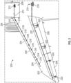
- the aircraft 200 includes a wing 202 that includes aerostructures 204, 206.
- Leading edge aerostructures 204 may be slats or the like and trailing edge aerostructures 206 may be flaps or the like.
- the leading edge aerostructures 204 may be controlled or operated by a first aerostructure actuator system 208 and the trailing edge aerostructures 206 may be controlled or operated by a second aerostructure actuator system 210.
- the first aerostructure actuator system 208 includes a drive mechanism 212, such as a motor and associated components.
- the drive mechanism 212 is operably coupled to, and configured to drive rotation of, a drive shaft 214.
- the drive shaft 214 may be a segmented drive shaft that coupled to one or more aerostructure actuators 216 that may be operably driven by the drive shaft 214.
- Each of the leading edge aerostructures 204 may be coupled to one or more of the aerostructure actuators 216. Actuation of the aerostructure actuators 216 causes a rotational and/or translational movement of a leading edge aerostructure 204 to which the aerostructure actuator(s) 216 is connected.
- the second aerostructure actuator system 210 includes a drive mechanism 218, such as a motor and associated components.
- the drive mechanism 218 is operably coupled to, and configured to drive rotation of, a drive shaft 220.
- the drive shaft 220 may be a segmented drive shaft that coupled to one or more aerostructure actuators 222 that may be operably driven by the drive shaft 220.
- Each of the trailing edge aerostructures 206 may be coupled to one or more of the aerostructure actuators 222. Actuation of the aerostructure actuators 222 causes a rotational and/or translational movement of a trailing edge aerostructure 206 to which the aerostructure actuator(s) 222 is connected.
- the drive shafts 214, 220 may be formed from a series of torque tubes that are arranged with the aerostructure actuators 216, 222 (or portions thereof) arranged between such torque tubes.
- the drive shafts 214, 220 When the drive shafts 214, 220 are rotated to drive actuation of the aerostructure actuators 216, 220, at times, the rotation must be stopped. During such events, the drive shaft 214, 220 will have inertia due to the rotational spinning and cannot stop immediately, and thus may continue to rotate after a commanded stop. Such stop may be initiated by a pilot or other aircraft operator commanding a flight operation. In other situations, the stop may be initiated by the aerostructure actuator systems 208, 210 itself.
- the aerostructure actuator systems 208, 210 may include sensors that are configured to monitor operation and loads of the aerostructures 204, 206 (e.g., skew sensors, disconnect sensors, torque sensors, etc.).
- the drive shafts 214, 220 may be configured with one or more slip-clutches that are arranged to decouple a portion of the drive shaft 214, 220 and thus prevent high loads to be imparted to the aerostructures.
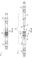
- FIGS. 3A-3B schematic illustrations of a portion of a drive shaft 300 for an aerostructure actuator system in accordance with an embodiment of the present disclosure are shown.
- the drive shaft 300 may be representative of two segments or portions of a drive shaft assembly that operably connects a drive mechanism (e.g., motor) to one or more aerostructure actuators, as will be appreciated by those of skill in the art.
- a drive mechanism e.g., motor
- the drive shaft 300 includes a first shaft portion 302 coupled to a second shaft portion 304 by a clutch assembly 306.
- the first and second shaft portions 302, 304 may be torque tubes or other structural elements, as will be appreciated by those of skill in the art.
- the clutch assembly 306 is arranged as a slip-clutch that is configured to disengage or decouple the rotation of the first shaft portion 302 from the second shaft portion 304.
- the first shaft portion 302 includes a first mandrel 308 that is sized to receive, at least, parts of the clutch assembly 306 and a second mandrel 310 of the second shaft portion 304.
- the clutch assembly 306 includes the first mandrel 308 and the second mandrel 310.
- the clutch assembly 306 includes a post 312, a first bearing 314, a spacer 316, a second bearing 318, a washer 320, and a load setting nut 322.
- the first mandrel 308 is configured to fixedly connect to the spacer 316.
- the spacer 316 is arranged between the first bearing 314 and the second bearing 318.
- the spacer 316 is secured or fixedly connected to the first mandrel by one or more fasteners 324.
- the spacer 316 when assembled within the clutch assembly 306, is positioned to engage or connect with bearing outer races of the first and second bearings 314, 318.
- the post 312 includes a post extension 326 about which the bearings 314, 318, the spacer 316, the washer 320, and the load setting nut 322 may be installed.
- the load setting nut 322 may threadedly attach to an end of the post extension 326, and the other components (e.g., the washer 320, the bearings 314, 318, and the spacer 316 may be configured to not directly attach to the post 312 or post extension 326).
- the outer race of the bearings 314, 318 are configured to engage with the spacer 316 which is fixedly attached to the first mandrel 308 of the first shaft portion 302.
- the inner race of the bearings 314, 318 are configured to engage with the post extension 326.
- the post extension 326 is an extension of the post 312, and the post 312 is configured to fixed attach to the second shaft portion 304 at the second mandrel 310.
- the post 312 is configured to be installed within an interior of the second mandrel 310 and may be fixedly attached thereto by one or more fasteners 328, as will be appreciated by those of skill in the art and illustratively shown in FIG. 3A .
- the first mandrel 308 In normal operation, when the first shaft portion 302 is rotated, the first mandrel 308 will rotate and the rotation may be conveyed through the spacer 316 and other elements of the clutch assembly 306 to cause rotation of the post 312, which in turn will cause rotation of the second mandrel 310 and thus rotation of the second shaft portion 304.
- This transmission of rotational energy from the first shaft portion 302 to the second shaft portion 304 may be achieve because during normal operation the two bearings 314, 318 are fixedly connected through the spacer 316 (e.g., by friction forces).
- the amount of friction between the bearings 314, 318 and the spacer 316 is controlled by the load setting nut 322. This selective frictional contact enables load setting and resetting of the clutch assembly 306 if such a reset of the components is necessary.
- the load setting nut is configured to threadedly engage with the post extension and apply a compressive force to the first bearing 314, the spacer 316, and the second bearing 318 against the post 312.
- This compressive force defines a coupling limit between the first shaft portion 302 and the second shaft portion 304 such that if a relative rotational speed between the first shaft portion 302 and the second shaft portion 304 exceeds a predefined limit (defined by the compressive force), the two shaft portions 302, 304 will rotationally decouple and prevent transmission of torque from one shaft portion to the other and thus limit the amount of load carried by the shaft portions.
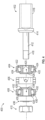
- FIG. 4 a schematic illustration of a clutch assembly 400 in accordance with an embodiment of the present disclosure is shown.
- the clutch assembly 400 may be integrated into an aerostructure actuator system for use onboard an aircraft and for controlling aerostructures of the aircraft. More particularly, as described above, the clutch assembly 400 may be part of a drive shaft of such aerostructure actuator system and may be arranged and provided to prevent over-torque or over-load events that can damage the drive shaft or other parts of the aerostructure actuator system.
- the clutch assembly 400 is a slip-clutch configuration that is adjustable to slip given a specific amount of force applied thereto.
- the clutch assembly 400 a post 402, a first bearing 404, a spacer 406, a second bearing 408, a washer 410, and a load setting nut 412.
- the post 402 comprises a post extension 412, a stop 414, and a shaft connector 416.
- the shaft connector 416 is configured to fixedly connect to a shaft or tube of a drive shaft.
- the stop 414 provides an end surface upon which components (e.g., the first bearing) can contact and engage with to impart rotational movement (e.g., through frictional contact).
- the post extension 412 includes a threaded portion 418 that is configured to receive and threadedly connect with the load setting nut 410.
- the post extension 412 may not include threading between the threaded portion 418 and the stop 414. This non-threaded portion allows for components to rotate freely about the post extension 412.
- the load setting nut 412 is configured to threadedly engage and connect to the post extension 412 at the threaded portion 418 thereof. Between the load setting nut 412 and the stop 414 of the post 402 are positioned the first bearing 404, the spacer 406, the second bearing 408, and the washer 410.
- the first bearing 404 includes an inner race 420, one or more bearing elements 422, and an outer race 424.
- the inner race 420, the bearing elements 422, and the outer race 424 form a concentric or annular arrangement about a central aperture 426 through which the post extension 412 may pass.
- the inner race 420 of the first bearing 404 is configured to frictionally engage with the stop 414.
- the outer race 424 of the first bearing 404 is configured to frictionally engage with the spacer 406.
- the bearing elements 422 are configured to be stationary relative to both the inner race 420 and the outer race 424 during normal operation.
- the inner and outer races 420, 424 have angled or wedged surfaces such that a compression of the two races 420, 424 determines the frictional engagement of the bearing elements 422 therebetween. If a predetermined torque is applied to one or both of the races 420, 424, the frictional engagement with the bearing elements 422 may be overcome, thus permitting relative rotation of the races 420, 424 and the components operably connected thereto. That is, the engagement between the inner and outer races 420, 424 may be decoupled upon a predetermined torque applied thereto.
- the spacer 406 is configured to be fixedly secured to a mandrel of a drive shaft, and thus is configured to be in locked communication with such structure. Such attachment may be by fastener, adhesives, welding, and the like, as will be appreciated by those of skill in the art.
- the second bearing 408 is similarly arranged and constructed as the first bearing 404.
- the second bearing 408 includes an inner race 428, one or more bearing elements 430, and an outer race 432.
- the second bearing 408 is a circumferential or annular structure with a central aperture 434 provided therein for installation of the second bearing 408 on the post extension 412 of the post 402.
- the outer race 432 of the second bearing 408 is configured to frictionally engage with the spacer 406.
- the inner race 428 of the second bearing 408 is configured to frictionally engage with the load setting nut 410 or a washer 434 that may be provided between the load setting nut 410 and the inner race 428 of the second bearing 408.
- the load setting nut 410 may be tightened on the threaded portion 418 of the post extension 412 to compress the washer 436, the first and second bearings 404, 408, and the spacer 406 between the load setting nut 410 and the stop 414 of the post 402. This compression applied by the load setting nut 410 enables tailoring of the torque or other forces that can overcome the frictional engagement of the components of the clutch assembly 400 and thus allow for relative rotational movement between the various components.
- the setting of the compression using the load setting nut 410 enables setting of a load limit that if exceeded the components of the clutch assembly 400 will decouple such that excessive inertia is not transferred from one side (e.g., from the first shaft portion 302 to the second shaft portion 304 shown in FIGS. 3A-3B ).
- This decoupling ensures that excessive loads and forces are not conveyed through the drive shaft, and thus damage to components thereof may be reduced or eliminated.
- the majority of the clutch assembly components in accordance with embodiments of the present disclosure are housed within a portion of the drive shaft.
- This small profile or package for the clutch assembly provides advantages over prior configuration which may be relatively large. In such prior configurations, a drive shaft portion would be attached to the clutch on either side and the clutch would sit between such shaft portions. Because of the size and weight of the clutch in such configurations, a high or large inertia would be present during a transition from a rotational state to a change to no rotation or a change in direction (e.g., reverse of the rotation) during flight maneuvers.
- the clutch assemblies of the present disclosure have low inertia due to a low/small profile, which reduces risk of damage to components of the clutch assembly, drive shaft, aerostructure actuator system, aerostructures, and/or associated components.
- FIGS. 5A-5B The low profile or small packaging of a clutch assembly in accordance with an embodiment of the present disclosure is shown in FIGS. 5A-5B.
- FIG. 5A illustrates a portion of a drive shaft 500 for an aerostructure actuator system in accordance with an embodiment of the present disclosure having a clutch assembly 502 installed within/relative to shaft portions 504, 506 of the drive shaft 500 of an aerostructure actuator system.
- FIG. 5B illustrates the clutch assembly 502 in isolation for explanatory and clarity purposes.
- the first shaft portion 504 has a first diameter D 1 and the second shaft portion 506 had a second diameter D 2 .
- the first diameter D 1 is equal to the second diameter D 2 .
- the first shaft portion 504 includes a respective first mandrel 508 and the second shaft portion 506 includes a respective second mandrel 510.
- the second mandrel 510 of the second shaft portion 506 is substantially the same or equal in diameter as the second shaft portion 506 (i.e., the second mandrel has a diameter equal to the second diameter D 2 of the second shaft portion 506).
- the first mandrel 508 of the first shaft portion 504 has an enlarged outer diameter D mo as compared to the diameter (first diameter D 1 ) of the first shaft portion 504. That is, the outer diameter D mo of the first mandrel 508 is enlarged as compared to the first diameter D 1 of the first shaft portion 504. Such increased size of the first mandrel 508 allows accommodation or installation of the clutch assembly 502 within the first mandrel 508, as shown in FIG. 5A .
- the first mandrel 508 is a hollow body housing to receive the clutch assembly 502 therein.
- the first mandrel 508 has an inner diameter D mi that is sized to receive the clutch assembly 502 and allow connection between the first mandrel 508 and a spacer 510 of the clutch assembly 502.
- fasteners or the like may be passed through the first mandrel 508 and fasten or engage with the spacer 510 to fixedly connect the spacer to the first mandrel 508 and thus to the first shaft portion 504.
- the spacer 510 has an outer diameter D c that defines the largest outer diameter of the clutch assembly 502.
- the outer diameter D c of the clutch assembly 502 being smaller but substantially equal to the inner diameter D mi of the first mandrel 508 allows for installation of the clutch assembly 502 within the first mandrel 508 and for a fastener to fixedly connect the spacer 510 to the first mandrel 508.
- the outer diameter D c of the clutch assembly 502 may be about the same dimension of the first and second diameters D 1 , D 2 of the shaft potions 504, 506 or only slightly larger than the first and second diameters D 1 , D 2 . In some non-limiting embodiments, the outer diameter D c of the clutch assembly 502 may be between 0% and 50% larger than the first and second diameters D 1 , D 2 of the shaft potions 504, 506. In some non-limiting embodiments, the outer diameter D c of the clutch assembly 502 may be less than the first and second diameters D 1 , D 2 of the shaft potions 504, 506.
- the outer diameter D mo of the first mandrel 508 may be between 0% and 50% larger than the first and second diameters D 1 , D 2 of the shaft potions 504, 506. From this perspective, the total maximum diameter may be defined by the outer diameter D mo of the first mandrel 508 that is configured to house the clutch assembly 502. This is in contrast to prior clutch assembly configurations where the clutch assembly may be positioned between (not in or around) two shaft portions and may have a sizing with an equivalent diameter being at least twice that of the shaft itself. This larger size is part of why such prior clutch assemblies had high inertia and could cause damage or other issues associated with operation of aerostructure actuator systems.
- one or more of the clutch assemblies described herein may be implemented within a drive shaft of an aerostructure actuator system.
- a single clutch assembly as described herein may be arranged between a drive mechanism (e.g., motor or the like) and a drive shaft that may be operably connected to one or more aerostructure actuators.
- multiple such clutch assemblies may be distributed along the length of a drive shaft, and thus allow for multiple different points of decoupling at the respective clutch, based on torque loads and/or the load setting of the load setting nuts of the clutch assemblies.
- each clutch assembly may be configured with a different threshold based on location and total loads at the specific location of the clutch assembly.
- a clutch assembly close to a drive mechanism may have a different load threshold (based on setting of the load setting nut) than a clutch assembly at the distal end of a drive shaft (e.g., proximate a tip or end of a wing).
- embodiments of the present disclosure provide for improved aerostructure actuator systems for use on aircraft.
- low profile, low inertia clutch systems are provided within aerostructure actuator systems to reduce potential for damage or other risks associated with high inertia situations.
- the total package of the clutch assembly is significantly smaller than prior clutch assemblies, thus providing improved weight and operation benefits.
- Secondary flight control systems may self-damage the aerostructure if a load exceeds an aircraft limit load.
- the integrated driveline slip-clutches described herein can protect key aerostructures by slipping the load prior to reaching the limit load of the aircraft.
- the slip-clutch assemblies are integrated into the drive line of the high lift system.
- the clutch assemblies described herein may be light weight and compact in design (e.g., fitting within a mandrel of a portion of a drive shaft), thus providing weight, volume, and operational benefits, as described herein.
- the terms may include a range of ⁇ 8%, or 5%, or 2% of a given value or other percentage change as will be appreciated by those of skill in the art for the particular measurement and/or dimensions referred to herein. It should be appreciated that relative positional terms such as “forward,” “aft,” “upper,” “lower,” “above,” “below,” and the like are with reference to normal operational attitude and should not be considered otherwise limiting.
Landscapes
- Engineering & Computer Science (AREA)
- Mechanical Engineering (AREA)
- General Engineering & Computer Science (AREA)
- Aviation & Aerospace Engineering (AREA)
- Automation & Control Theory (AREA)
- Mechanical Operated Clutches (AREA)
- Transmission Devices (AREA)
Abstract
Description
- Embodiments of the present disclosure are directed to actuator systems and, more specifically, to actuator systems for rotating one or more structures, such as aerostructures (e.g., flaps, slats, alerions, etc.) and other actuatable structures.
- Wing sections of fixed wing aircraft may include geared rotary actuator(s) at a hinge line between an aft section of a wing and the aerostructure (e.g., flaps, slats, etc.). Conventionally, aerostructures are controlled using an actuator within the wing that is operably connected to such aerostructure(s). Aerostructures may be prone to damage if a load exceeds an aircraft limit load. For example, during high load events, a drive shaft or the like associated with the actuator system may cause damage to the aerostructure by applying to great of a torque.
- According to some embodiments, aerostructure actuator systems are provided. The aerostructure actuator systems include a first shaft portion having a first mandrel, a second shaft portion having a second mandrel, and a clutch assembly arranged within the first mandrel and configured to operably connect the first shaft portion to the second shaft portion. The clutch assembly includes a post fixedly connected to the second mandrel, the post having a post extension extending therefrom, a first bearing installed on the post extension, a portion of the first bearing frictionally engaging with a portion of the post, a second bearing installed on the post, a spacer arranged between the first bearing and the second bearing, wherein the spacer is configured to fixedly attach to the first mandrel, and a load setting nut configured to threadedly engage with the post extension and apply a compressive force to the first bearing, spacer, and the second bearing against the post, wherein the compressive force defines a coupling limit between the first shaft portion and the second shaft portion. The clutch assembly is configured to rotationally decouple the first shaft portion from the second shaft portion if a relative rotational speed between the first shaft portion and the second shaft portion exceeds the coupling limit.
- In addition to one or more of the features described herein, or as an alternative, further embodiments of the aerostructure actuator systems may include that the first shaft portion and the second shaft portion form a part of a drive shaft of the aerostructure actuator system.
- In addition to one or more of the features described herein, or as an alternative, further embodiments of the aerostructure actuator systems may include that the drive shaft is operably coupled to a drive mechanism that is configured to rotationally drive the drive shaft.
- In addition to one or more of the features described herein, or as an alternative, further embodiments of the aerostructure actuator systems may include that the drive mechanism is a motor.
- In addition to one or more of the features described herein, or as an alternative, further embodiments of the aerostructure actuator systems may include an aerostructure actuator operably coupled to one of the first shaft portion and the second shaft portion.
- In addition to one or more of the features described herein, or as an alternative, further embodiments of the aerostructure actuator systems may include an aerostructure operably coupled to the aerostructure actuator.
- In addition to one or more of the features described herein, or as an alternative, further embodiments of the aerostructure actuator systems may include that the aerostructure is a slat or flap of an aircraft.
- In addition to one or more of the features described herein, or as an alternative, further embodiments of the aerostructure actuator systems may include that each of the first bearing and the second bearing comprise an inner race, an outer race, and one or more bearing elements arranged therebetween.
- In addition to one or more of the features described herein, or as an alternative, further embodiments of the aerostructure actuator systems may include that the first mandrel has an outer diameter and an inner diameter and the clutch assembly has an outer diameter that is less than the inner diameter of the first mandrel.
- In addition to one or more of the features described herein, or as an alternative, further embodiments of the aerostructure actuator systems may include that the first shaft portion has as first diameter and the clutch assembly has an outer diameter that is equal to or greater than the first diameter.
- In addition to one or more of the features described herein, or as an alternative, further embodiments of the aerostructure actuator systems may include that the outer diameter of the clutch assembly is between 0% and 50% larger than the first diameter.
- In addition to one or more of the features described herein, or as an alternative, further embodiments of the aerostructure actuator systems may include that the second shaft portion has a second diameter that is equal to the first diameter.
- In addition to one or more of the features described herein, or as an alternative, further embodiments of the aerostructure actuator systems may include that the clutch assembly further comprises a washer arranged between the load setting nut and the second bearing.
- In addition to one or more of the features described herein, or as an alternative, further embodiments of the aerostructure actuator systems may include that a portion of the post fits within the second mandrel.
- In addition to one or more of the features described herein, or as an alternative, further embodiments of the aerostructure actuator systems may include that the post comprises a stop and the first bearing frictionally engages with the stop.
- According to some embodiments, aircraft are provided. The aircraft include an aerostructure and an aerostructure actuator system. The aerostructure actuator system includes an aerostructure actuator operably coupled to the aerostructure, a drive shaft configured to drive operation of the aerostructure actuator and comprising a first shaft portion having a first mandrel and a second shaft portion having a second mandrel, and a clutch assembly arranged within the first mandrel and configured to operably connect the first shaft portion to the second shaft portion. The clutch assembly includes a post fixedly connected to the second mandrel, the post having a post extension extending therefrom, a first bearing installed on the post extension, a portion of the first bearing frictionally engages with a portion of the post, a second bearing installed on the post, a spacer arranged between the first bearing and the second bearing, wherein the spacer is configured to fixedly attach to the first mandrel, and a load setting nut configured to threadedly engage with the post extension and apply a compressive force to the first bearing, spacer, and the second bearing against the post, wherein the compressive force defines a coupling limit between the first shaft portion and the second shaft portion. The clutch assembly is configured to rotationally decouple the first shaft portion from the second shaft portion if a relative rotational speed between the first shaft portion and the second shaft portion exceeds the coupling limit.
- In addition to one or more of the features described herein, or as an alternative, further embodiments of the aircraft may include that the aerostructure is a flap or slat.
- In addition to one or more of the features described herein, or as an alternative, further embodiments of the aircraft may include that the drive shaft comprises a plurality of clutch assemblies distributed along a length of the drive shaft.
- In addition to one or more of the features described herein, or as an alternative, further embodiments of the aircraft may include a drive mechanism operably coupled to the drive shaft.
- In addition to one or more of the features described herein, or as an alternative, further embodiments of the aircraft may include that the wherein the first shaft portion has as first diameter and the clutch assembly has an outer diameter that is between 0% and 50% larger than the first diameter.
- The foregoing features and elements may be combined in various combinations without exclusivity, unless expressly indicated otherwise. These features and elements as well as the operation thereof will become more apparent in light of the following description and the accompanying drawings. It should be understood, however, that the following description and drawings are intended to be illustrative and explanatory in nature and non-limiting.
- The following descriptions should not be considered limiting in any way. With reference to the accompanying drawings, like elements are numbered alike:
-
FIG. 1 is a schematic illustration of an aircraft that can include aerostructures and associated aerostructure actuator systems in accordance with embodiments of the present disclosure; -
FIG. 2 is a schematic illustration of a wing of an aircraft that can include aerostructure actuator systems in accordance with embodiments of the present disclosure; -
FIG. 3A is a schematic illustration of a portion of a drive shaft for an aerostructure actuator system in accordance with an embodiment of the present disclosure; -
FIG. 3B is a schematic illustration of the drive shaft ofFIG. 3A with the parts thereof separated; -
FIG. 4 is a schematic illustration of a clutch assembly in accordance with an embodiment of the present disclosure; -
FIG. 5A is a schematic illustration of a portion of a drive shaft having a clutch assembly in accordance with an embodiment of the present disclosure; and -
FIG. 5B is a schematic illustration of the clutch assembly ofFIG. 5A . - A detailed description of one or more embodiments of the disclosed apparatus and method are presented herein by way of exemplification and not limitation with reference to the Figures.
-
FIG. 1 illustrates an example of anaircraft 100 having aircraft engines surrounded by (or otherwise carried in)nacelles 102. Theaircraft 100 includeswings 104 that extend from anaircraft fuselage 106. Eachwing 104 may include one ormore slats 108 on a forward edge or leading edge and one ormore flaps 110 on an aft, rear, or trailing edge thereof. Thewings 104 may also includeailerons 112 on the trailing edges, as will be appreciated by those of skill in the art. Theaircraft 100, as shown, includes atail structure 114 which can include various flaps, ailerons, slats, and the like, as will be appreciated by those of skill in the art. The flaps, slats, ailerons, and the like are generally referred to herein as "aerostructures" as they are movable under aircraft power systems and are configured to control flight and motion of theaircraft 100. Anaerostructure actuator system 116 may be connected to one or more of the aerostructures. For example, eachwing 104 and thetail structure 114 may include one or moreaerostructure actuator systems 116. Theaerostructure actuator systems 116 may be operably connected to the various aerostructures and configured control the operation/position of the aerostructures to control flight of theaircraft 100. - Aircraft and associated components and systems may be limited by load applications, such that aircraft load limits are imposed to prevent damage to the aircraft, components of the aircraft, or negatively impact slight of the aircraft. For example, secondary flight control systems may self-damage the aerostructure if a load exceeds an aircraft limit load. In view of this potential self-imposed damage, embodiments of the present disclosure are directed to systems for preventing over torque and other excess loads that could damage aerostructures. To achieve this, a driveline of the actuator system is provided with an integrated driveline slip-clutch that is configured to protect key aerostructures by slipping a load prior to reaching a limit load of the aircraft.
- Referring now to
FIG. 2 , a schematic illustration of a portion of anaircraft 200 that may incorporate embodiments of the present disclosure is shown. Theaircraft 200 includes awing 202 that includesaerostructures edge aerostructures 204 may be slats or the like and trailingedge aerostructures 206 may be flaps or the like. Theleading edge aerostructures 204 may be controlled or operated by a firstaerostructure actuator system 208 and the trailingedge aerostructures 206 may be controlled or operated by a secondaerostructure actuator system 210. - The first
aerostructure actuator system 208 includes adrive mechanism 212, such as a motor and associated components. Thedrive mechanism 212 is operably coupled to, and configured to drive rotation of, adrive shaft 214. Thedrive shaft 214 may be a segmented drive shaft that coupled to one or moreaerostructure actuators 216 that may be operably driven by thedrive shaft 214. Each of theleading edge aerostructures 204 may be coupled to one or more of theaerostructure actuators 216. Actuation of theaerostructure actuators 216 causes a rotational and/or translational movement of aleading edge aerostructure 204 to which the aerostructure actuator(s) 216 is connected. - The second
aerostructure actuator system 210 includes adrive mechanism 218, such as a motor and associated components. Thedrive mechanism 218 is operably coupled to, and configured to drive rotation of, adrive shaft 220. Thedrive shaft 220 may be a segmented drive shaft that coupled to one or moreaerostructure actuators 222 that may be operably driven by thedrive shaft 220. Each of the trailingedge aerostructures 206 may be coupled to one or more of theaerostructure actuators 222. Actuation of theaerostructure actuators 222 causes a rotational and/or translational movement of a trailingedge aerostructure 206 to which the aerostructure actuator(s) 222 is connected. - The
drive shafts aerostructure actuators 216, 222 (or portions thereof) arranged between such torque tubes. When thedrive shafts aerostructure actuators drive shaft aerostructure actuator systems aerostructure actuator systems aerostructures 204, 206 (e.g., skew sensors, disconnect sensors, torque sensors, etc.). In accordance with embodiments of the present disclosure, thedrive shafts drive shaft - Referring now to
FIGS. 3A-3B , schematic illustrations of a portion of adrive shaft 300 for an aerostructure actuator system in accordance with an embodiment of the present disclosure are shown. Thedrive shaft 300 may be representative of two segments or portions of a drive shaft assembly that operably connects a drive mechanism (e.g., motor) to one or more aerostructure actuators, as will be appreciated by those of skill in the art. - The
drive shaft 300 includes afirst shaft portion 302 coupled to asecond shaft portion 304 by aclutch assembly 306. The first andsecond shaft portions clutch assembly 306 is arranged as a slip-clutch that is configured to disengage or decouple the rotation of thefirst shaft portion 302 from thesecond shaft portion 304. - The
first shaft portion 302 includes afirst mandrel 308 that is sized to receive, at least, parts of theclutch assembly 306 and asecond mandrel 310 of thesecond shaft portion 304. Theclutch assembly 306 includes thefirst mandrel 308 and thesecond mandrel 310. Thefirst mandrel 308, in this specific illustrative embodiment, defines a housing for the other components of theclutch assembly 306 to fit within. Theclutch assembly 306 includes apost 312, afirst bearing 314, aspacer 316, asecond bearing 318, awasher 320, and aload setting nut 322. - In this configuration, the
first mandrel 308 is configured to fixedly connect to thespacer 316. Thespacer 316 is arranged between thefirst bearing 314 and thesecond bearing 318. Thespacer 316 is secured or fixedly connected to the first mandrel by one ormore fasteners 324. Thespacer 316, when assembled within theclutch assembly 306, is positioned to engage or connect with bearing outer races of the first andsecond bearings post 312 includes apost extension 326 about which thebearings spacer 316, thewasher 320, and theload setting nut 322 may be installed. In this configuration, theload setting nut 322 may threadedly attach to an end of thepost extension 326, and the other components (e.g., thewasher 320, thebearings spacer 316 may be configured to not directly attach to thepost 312 or post extension 326). - As noted, the outer race of the
bearings spacer 316 which is fixedly attached to thefirst mandrel 308 of thefirst shaft portion 302. The inner race of thebearings post extension 326. Thepost extension 326 is an extension of thepost 312, and thepost 312 is configured to fixed attach to thesecond shaft portion 304 at thesecond mandrel 310. In this illustrative embodiment, thepost 312 is configured to be installed within an interior of thesecond mandrel 310 and may be fixedly attached thereto by one ormore fasteners 328, as will be appreciated by those of skill in the art and illustratively shown inFIG. 3A . - In normal operation, when the
first shaft portion 302 is rotated, thefirst mandrel 308 will rotate and the rotation may be conveyed through thespacer 316 and other elements of theclutch assembly 306 to cause rotation of thepost 312, which in turn will cause rotation of thesecond mandrel 310 and thus rotation of thesecond shaft portion 304. This transmission of rotational energy from thefirst shaft portion 302 to thesecond shaft portion 304 may be achieve because during normal operation the twobearings bearings spacer 316 is controlled by theload setting nut 322. This selective frictional contact enables load setting and resetting of theclutch assembly 306 if such a reset of the components is necessary. - The load setting nut is configured to threadedly engage with the post extension and apply a compressive force to the
first bearing 314, thespacer 316, and thesecond bearing 318 against thepost 312. This compressive force defines a coupling limit between thefirst shaft portion 302 and thesecond shaft portion 304 such that if a relative rotational speed between thefirst shaft portion 302 and thesecond shaft portion 304 exceeds a predefined limit (defined by the compressive force), the twoshaft portions - Turning now to
FIG. 4 , a schematic illustration of aclutch assembly 400 in accordance with an embodiment of the present disclosure is shown. Theclutch assembly 400 may be integrated into an aerostructure actuator system for use onboard an aircraft and for controlling aerostructures of the aircraft. More particularly, as described above, theclutch assembly 400 may be part of a drive shaft of such aerostructure actuator system and may be arranged and provided to prevent over-torque or over-load events that can damage the drive shaft or other parts of the aerostructure actuator system. - Similar to the embodiment of
FIGS. 3A-3B , theclutch assembly 400 is a slip-clutch configuration that is adjustable to slip given a specific amount of force applied thereto. The clutch assembly 400 apost 402, afirst bearing 404, aspacer 406, asecond bearing 408, awasher 410, and aload setting nut 412. Thepost 402 comprises apost extension 412, astop 414, and ashaft connector 416. Theshaft connector 416 is configured to fixedly connect to a shaft or tube of a drive shaft. Thestop 414 provides an end surface upon which components (e.g., the first bearing) can contact and engage with to impart rotational movement (e.g., through frictional contact). Thepost extension 412 includes a threadedportion 418 that is configured to receive and threadedly connect with theload setting nut 410. In some configurations, thepost extension 412 may not include threading between the threadedportion 418 and thestop 414. This non-threaded portion allows for components to rotate freely about thepost extension 412. - The
load setting nut 412 is configured to threadedly engage and connect to thepost extension 412 at the threadedportion 418 thereof. Between theload setting nut 412 and thestop 414 of thepost 402 are positioned thefirst bearing 404, thespacer 406, thesecond bearing 408, and thewasher 410. Thefirst bearing 404 includes aninner race 420, one ormore bearing elements 422, and anouter race 424. Theinner race 420, the bearingelements 422, and theouter race 424 form a concentric or annular arrangement about acentral aperture 426 through which thepost extension 412 may pass. Theinner race 420 of thefirst bearing 404 is configured to frictionally engage with thestop 414. Theouter race 424 of thefirst bearing 404 is configured to frictionally engage with thespacer 406. The bearingelements 422 are configured to be stationary relative to both theinner race 420 and theouter race 424 during normal operation. The inner andouter races races elements 422 therebetween. If a predetermined torque is applied to one or both of theraces elements 422 may be overcome, thus permitting relative rotation of theraces outer races - The
spacer 406 is configured to be fixedly secured to a mandrel of a drive shaft, and thus is configured to be in locked communication with such structure. Such attachment may be by fastener, adhesives, welding, and the like, as will be appreciated by those of skill in the art. On the opposite side of thespacer 406 from thefirst bearing 404 is thesecond bearing 408. Thesecond bearing 408 is similarly arranged and constructed as thefirst bearing 404. Thesecond bearing 408 includes aninner race 428, one ormore bearing elements 430, and anouter race 432. Thesecond bearing 408 is a circumferential or annular structure with acentral aperture 434 provided therein for installation of thesecond bearing 408 on thepost extension 412 of thepost 402. Similar to thefirst bearing 404, theouter race 432 of thesecond bearing 408 is configured to frictionally engage with thespacer 406. Theinner race 428 of thesecond bearing 408 is configured to frictionally engage with theload setting nut 410 or awasher 434 that may be provided between theload setting nut 410 and theinner race 428 of thesecond bearing 408. - The
load setting nut 410 may be tightened on the threadedportion 418 of thepost extension 412 to compress thewasher 436, the first andsecond bearings spacer 406 between theload setting nut 410 and thestop 414 of thepost 402. This compression applied by theload setting nut 410 enables tailoring of the torque or other forces that can overcome the frictional engagement of the components of theclutch assembly 400 and thus allow for relative rotational movement between the various components. That is, the setting of the compression using theload setting nut 410 enables setting of a load limit that if exceeded the components of theclutch assembly 400 will decouple such that excessive inertia is not transferred from one side (e.g., from thefirst shaft portion 302 to thesecond shaft portion 304 shown inFIGS. 3A-3B ). This decoupling ensures that excessive loads and forces are not conveyed through the drive shaft, and thus damage to components thereof may be reduced or eliminated. - As illustratively shown and described herein, the majority of the clutch assembly components in accordance with embodiments of the present disclosure are housed within a portion of the drive shaft. This small profile or package for the clutch assembly provides advantages over prior configuration which may be relatively large. In such prior configurations, a drive shaft portion would be attached to the clutch on either side and the clutch would sit between such shaft portions. Because of the size and weight of the clutch in such configurations, a high or large inertia would be present during a transition from a rotational state to a change to no rotation or a change in direction (e.g., reverse of the rotation) during flight maneuvers. This high inertia results in continued rotation after a commanded change, and such continued rotation may cause damage to components that are commanded to operate differently from a prior state of operation. Advantageously, the clutch assemblies of the present disclosure have low inertia due to a low/small profile, which reduces risk of damage to components of the clutch assembly, drive shaft, aerostructure actuator system, aerostructures, and/or associated components.
- The low profile or small packaging of a clutch assembly in accordance with an embodiment of the present disclosure is shown in
FIGS. 5A-5B. FIG. 5A illustrates a portion of adrive shaft 500 for an aerostructure actuator system in accordance with an embodiment of the present disclosure having aclutch assembly 502 installed within/relative toshaft portions drive shaft 500 of an aerostructure actuator system.FIG. 5B illustrates theclutch assembly 502 in isolation for explanatory and clarity purposes. - As shown in
FIG. 5A , thefirst shaft portion 504 has a first diameter D1 and thesecond shaft portion 506 had a second diameter D2. In some configurations the first diameter D1 is equal to the second diameter D2. Thefirst shaft portion 504 includes a respectivefirst mandrel 508 and thesecond shaft portion 506 includes a respectivesecond mandrel 510. In this illustrative embodiment, thesecond mandrel 510 of thesecond shaft portion 506 is substantially the same or equal in diameter as the second shaft portion 506 (i.e., the second mandrel has a diameter equal to the second diameter D2 of the second shaft portion 506). Thefirst mandrel 508 of thefirst shaft portion 504 has an enlarged outer diameter Dmo as compared to the diameter (first diameter D1) of thefirst shaft portion 504. That is, the outer diameter Dmo of thefirst mandrel 508 is enlarged as compared to the first diameter D1 of thefirst shaft portion 504. Such increased size of thefirst mandrel 508 allows accommodation or installation of theclutch assembly 502 within thefirst mandrel 508, as shown inFIG. 5A . Thefirst mandrel 508 is a hollow body housing to receive theclutch assembly 502 therein. Thefirst mandrel 508 has an inner diameter Dmi that is sized to receive theclutch assembly 502 and allow connection between thefirst mandrel 508 and aspacer 510 of theclutch assembly 502. For example, as shown and described above, fasteners or the like may be passed through thefirst mandrel 508 and fasten or engage with thespacer 510 to fixedly connect the spacer to thefirst mandrel 508 and thus to thefirst shaft portion 504. - To allow for the fastening connection between the
first mandrel 508 and thespacer 510 of theclutch assembly 502, thespacer 510 has an outer diameter Dc that defines the largest outer diameter of theclutch assembly 502. By having the outer diameter Dc of theclutch assembly 502 being smaller but substantially equal to the inner diameter Dmi of thefirst mandrel 508 allows for installation of theclutch assembly 502 within thefirst mandrel 508 and for a fastener to fixedly connect thespacer 510 to thefirst mandrel 508. In some non-limiting embodiments, the outer diameter Dc of theclutch assembly 502 may be about the same dimension of the first and second diameters D1, D2 of theshaft potions clutch assembly 502 may be between 0% and 50% larger than the first and second diameters D1, D2 of theshaft potions clutch assembly 502 may be less than the first and second diameters D1, D2 of theshaft potions first mandrel 508 may be between 0% and 50% larger than the first and second diameters D1, D2 of theshaft potions first mandrel 508 that is configured to house theclutch assembly 502. This is in contrast to prior clutch assembly configurations where the clutch assembly may be positioned between (not in or around) two shaft portions and may have a sizing with an equivalent diameter being at least twice that of the shaft itself. This larger size is part of why such prior clutch assemblies had high inertia and could cause damage or other issues associated with operation of aerostructure actuator systems. - It will be appreciated that one or more of the clutch assemblies described herein may be implemented within a drive shaft of an aerostructure actuator system. In some embodiments, a single clutch assembly as described herein may be arranged between a drive mechanism (e.g., motor or the like) and a drive shaft that may be operably connected to one or more aerostructure actuators. In other embodiments, multiple such clutch assemblies may be distributed along the length of a drive shaft, and thus allow for multiple different points of decoupling at the respective clutch, based on torque loads and/or the load setting of the load setting nuts of the clutch assemblies. In such multi-assembly systems, each clutch assembly may be configured with a different threshold based on location and total loads at the specific location of the clutch assembly. As such, a clutch assembly close to a drive mechanism may have a different load threshold (based on setting of the load setting nut) than a clutch assembly at the distal end of a drive shaft (e.g., proximate a tip or end of a wing).
- Advantageously, embodiments of the present disclosure provide for improved aerostructure actuator systems for use on aircraft. In accordance with some embodiments, low profile, low inertia clutch systems are provided within aerostructure actuator systems to reduce potential for damage or other risks associated with high inertia situations. The total package of the clutch assembly is significantly smaller than prior clutch assemblies, thus providing improved weight and operation benefits. Secondary flight control systems may self-damage the aerostructure if a load exceeds an aircraft limit load. The integrated driveline slip-clutches described herein can protect key aerostructures by slipping the load prior to reaching the limit load of the aircraft. In accordance with some embodiments of the present disclosure, the slip-clutch assemblies are integrated into the drive line of the high lift system. The compression of the bearing within the slip-clutch to the plate or spacer determines the setting of the slip load. The slip is resettable when the load is reduced below the set slip load or when the rotation stops. Advantageously, the clutch assemblies described herein may be light weight and compact in design (e.g., fitting within a mandrel of a portion of a drive shaft), thus providing weight, volume, and operational benefits, as described herein.
- The use of the terms "a", "an", "the", and similar references in the context of description (especially in the context of the following claims) are to be construed to cover both the singular and the plural, unless otherwise indicated herein or specifically contradicted by context. The modifier "about" used in connection with a quantity is inclusive of the stated value and has the meaning dictated by the context (e.g., it includes the degree of error associated with measurement of the particular quantity). All ranges disclosed herein are inclusive of the endpoints, and the endpoints are independently combinable with each other. As used herein, the terms "about" and "substantially" are intended to include the degree of error associated with measurement of the particular quantity based upon the equipment available at the time of filing the application. For example, the terms may include a range of ± 8%, or 5%, or 2% of a given value or other percentage change as will be appreciated by those of skill in the art for the particular measurement and/or dimensions referred to herein. It should be appreciated that relative positional terms such as "forward," "aft," "upper," "lower," "above," "below," and the like are with reference to normal operational attitude and should not be considered otherwise limiting.
- While the present disclosure has been described with reference to an exemplary embodiment or embodiments, it will be understood by those skilled in the art that various changes may be made, and equivalents may be substituted for elements thereof without departing from the scope of the present disclosure. In addition, many modifications may be made to adapt a particular situation or material to the teachings of the present disclosure without departing from the essential scope thereof. Therefore, it is intended that the present disclosure not be limited to the particular embodiment disclosed as the best mode contemplated for carrying out this present disclosure, but that the present disclosure will include all embodiments falling within the scope of the claims.
Claims (15)
- An aerostructure actuator system comprising:a first shaft portion (302) having a first mandrel (308);a second shaft portion (304) having a second mandrel (310); anda clutch assembly (306) arranged within the first mandrel (308) and configured to operably connect the first shaft portion (302) to the second shaft portion (304), wherein the clutch assembly (306) comprising:a post (312) fixedly connected to the second mandrel (310), the post (312) having a post extension (412) extending therefrom;a first bearing (314) installed on the post extension, a portion of the first bearing frictionally engaging with a portion of the post;a second bearing (318) installed on the post;a spacer (316) arranged between the first bearing and the second bearing, wherein the spacer is configured to fixedly attach to the first mandrel; anda load setting nut (322) configured to threadedly engage with the post extension and apply a compressive force to the first bearing, spacer, and the second bearing against the post, wherein the compressive force defines a coupling limit between the first shaft portion and the second shaft portion,wherein the clutch assembly (306) is configured to rotationally decouple the first shaft portion from the second shaft portion if a relative rotational speed between the first shaft portion and the second shaft portion exceeds the coupling limit.
- The system of claim 1, wherein the first shaft portion (302) and the second shaft portion (304) form a part of a drive shaft of the aerostructure actuator system.
- The system of claim 2, wherein the drive shaft is operably coupled to a drive mechanism that is configured to rotationally drive the drive shaft.
- The system of claim 3, wherein the drive mechanism is a motor.
- The system of any preceding claim, further comprising an aerostructure actuator operably coupled to one of the first shaft portion and the second shaft portion.
- The system of claim 5, further comprising an aerostructure operably coupled to the aerostructure actuator, and preferably wherein the aerostructure is a slat or flap of an aircraft.
- The system of any preceding claim, wherein each of the first bearing (314) and the second bearing (318) comprise an inner race, an outer race, and one or more bearing elements arranged therebetween.
- The system of any preceding claim, wherein the first mandrel (308) has an outer diameter and an inner diameter and the clutch assembly (306) has an outer diameter that is less than the inner diameter of the first mandrel.
- The system of any preceding claim, wherein the first shaft portion (302) has as first diameter and the clutch assembly (306) has an outer diameter that is equal to or greater than the first diameter.
- The system of claim 9, wherein the outer diameter of the clutch assembly (306) is between 0% and 50% larger than the first diameter; or
wherein the second shaft portion (304) has a second diameter that is equal to the first diameter. - The system of any preceding claim, wherein the clutch assembly (306) further comprises a washer arranged between the load setting nut and the second bearing.
- The system of any preceding claim, wherein a portion of the post fits within the second mandrel (310).
- The system of claim 1, wherein the post (312) comprises a stop and the first bearing frictionally engages with the stop.
- An aircraft comprising:an aerostructure; andan aerostructure actuator system, as claimed in claim 1:an aerostructure actuator operably coupled to the aerostructure;a drive shaft configured to drive operation of the aerostructure actuator and comprising the first shaft portion having the first mandrel and the second shaft portion having the second mandrel.
- The aircraft of claim 14, wherein the drive shaft comprises a plurality of clutch assemblies distributed along a length of the drive shaft.
Applications Claiming Priority (1)
| Application Number | Priority Date | Filing Date | Title |
|---|---|---|---|
| US17/584,521 US11649039B1 (en) | 2022-01-26 | 2022-01-26 | Aerostructure actuation system |
Publications (2)
| Publication Number | Publication Date |
|---|---|
| EP4219297A1 true EP4219297A1 (en) | 2023-08-02 |
| EP4219297B1 EP4219297B1 (en) | 2024-10-23 |
Family
ID=84901547
Family Applications (1)
| Application Number | Title | Priority Date | Filing Date |
|---|---|---|---|
| EP23150903.5A Active EP4219297B1 (en) | 2022-01-26 | 2023-01-10 | Aerostructure actuation system |
Country Status (3)
| Country | Link |
|---|---|
| US (1) | US11649039B1 (en) |
| EP (1) | EP4219297B1 (en) |
| CA (1) | CA3185269A1 (en) |
Citations (4)
| Publication number | Priority date | Publication date | Assignee | Title |
|---|---|---|---|---|
| CA2776713A1 (en) * | 2011-05-16 | 2012-11-16 | Brian K. Bosk | Wedge clutch assembly |
| EP2695810A1 (en) * | 2012-08-09 | 2014-02-12 | Airbus Operations GmbH | Drive system for control surfaces of an aircraft |
| EP2709904A2 (en) * | 2011-05-20 | 2014-03-26 | The Boeing Company | Shape memory alloy actuator system and method |
| US20150298909A1 (en) * | 2012-11-19 | 2015-10-22 | Kiener Maschinenbau Gmbh | Friction drive for force transmission, in particular for a transport conveying device |
Family Cites Families (13)
| Publication number | Priority date | Publication date | Assignee | Title |
|---|---|---|---|---|
| US2547137A (en) * | 1948-12-06 | 1951-04-03 | Bendix Aviat Corp | Electromagnet overload release clutch |
| CN1922418B (en) | 2004-02-24 | 2010-08-04 | 利纳克有限公司 | Linear actuator with overload clutch |
| DE102004039264A1 (en) | 2004-08-13 | 2006-02-23 | Valeo Sicherheitssysteme Gmbh | Electromagnetic friction clutch, method of operation thereof and use within a drive train for automatically actuating a vehicle door or vehicle door |
| GB0616730D0 (en) | 2006-08-23 | 2006-10-04 | Airbus Uk Ltd | Jam-tolerant actuator |
| US8960031B2 (en) | 2009-09-01 | 2015-02-24 | Parker-Hannifin Corporation | Aircraft stabilizer actuator |
| GB201219560D0 (en) | 2012-10-31 | 2012-12-12 | Goodrich Actuation Systems Ltd | Actuator arrangement |
| EP2803584B1 (en) | 2013-05-17 | 2015-09-16 | Airbus Operations GmbH | Actuation system for flight control surface |
| EP2902314B1 (en) | 2014-01-29 | 2017-07-19 | Airbus Operations GmbH | High lift system for an aircraft and aircraft having such a high lift system |
| US9703312B2 (en) | 2015-09-29 | 2017-07-11 | Moog Inc. | Non-jamming stop module for high revolution applications |
| US10538310B2 (en) | 2016-06-29 | 2020-01-21 | Parker-Hannifin Corporation | Near synchronous distributed hydraulic motor driven actuation system |
| AU2018102213A4 (en) | 2017-03-24 | 2021-07-22 | Honeycomb Media Pty Ltd | System and method for providing information |
| EP3620372A1 (en) | 2018-09-04 | 2020-03-11 | Bombardier Inc. | High-lift actuation system with clutch architecture |
| EP3865725B1 (en) | 2020-02-17 | 2024-03-27 | Ratier-Figeac SAS | Torque limiter |
-
2022
- 2022-01-26 US US17/584,521 patent/US11649039B1/en active Active
- 2022-12-15 CA CA3185269A patent/CA3185269A1/en active Pending
-
2023
- 2023-01-10 EP EP23150903.5A patent/EP4219297B1/en active Active
Patent Citations (4)
| Publication number | Priority date | Publication date | Assignee | Title |
|---|---|---|---|---|
| CA2776713A1 (en) * | 2011-05-16 | 2012-11-16 | Brian K. Bosk | Wedge clutch assembly |
| EP2709904A2 (en) * | 2011-05-20 | 2014-03-26 | The Boeing Company | Shape memory alloy actuator system and method |
| EP2695810A1 (en) * | 2012-08-09 | 2014-02-12 | Airbus Operations GmbH | Drive system for control surfaces of an aircraft |
| US20150298909A1 (en) * | 2012-11-19 | 2015-10-22 | Kiener Maschinenbau Gmbh | Friction drive for force transmission, in particular for a transport conveying device |
Also Published As
| Publication number | Publication date |
|---|---|
| EP4219297B1 (en) | 2024-10-23 |
| US11649039B1 (en) | 2023-05-16 |
| CA3185269A1 (en) | 2023-07-26 |
Similar Documents
| Publication | Publication Date | Title |
|---|---|---|
| US11097830B2 (en) | Hybrid torque limiting rotary no-back device | |
| EP3128196B1 (en) | Torque tube assemblies for use with aircraft high lift devices | |
| EP3677503B1 (en) | Actuator assembly for moving an aircraft wing tip device | |
| US8393568B2 (en) | Enhanced lubrication skewed roller clutch assembly and actuator including same | |
| CN106958636B (en) | Linear actuator system with circumferentially and axially adjustable end stop assembly | |
| US4971267A (en) | Multi-fuseable shaft | |
| EP2280194B1 (en) | Rotary actuator | |
| EP3613667B1 (en) | Linear actuator with testable cone no-back and torque limiter | |
| US20140135132A1 (en) | Non-chattering ball detent torque limiter | |
| US9039538B2 (en) | Non-chattering ball detent torque limiter | |
| CN106464115A (en) | Electromagnetic actuator with magnetic torque limiter | |
| US11649039B1 (en) | Aerostructure actuation system | |
| EP4206490B1 (en) | A trim horizontal stabiliser actuator comprising an electromechanical linear actuator | |
| EP3395680A1 (en) | Interconnect drive system | |
| EP3061988A2 (en) | Shock absorber assembly for power drive unit of a vehicle | |
| US11719339B2 (en) | Low drag torque limiter for electric TRAS | |
| US12384526B2 (en) | Spoiler actuator | |
| US20250145276A1 (en) | Linear actuator for a flight control surface | |
| BR102022025547A2 (en) | AEROSTRUCTURE ACTUATOR SYSTEM, AND, AIRCRAFT | |
| WO2014116333A2 (en) | Non-chattering ball detent torque limiter |
Legal Events
| Date | Code | Title | Description |
|---|---|---|---|
| PUAI | Public reference made under article 153(3) epc to a published international application that has entered the european phase |
Free format text: ORIGINAL CODE: 0009012 |
|
| STAA | Information on the status of an ep patent application or granted ep patent |
Free format text: STATUS: THE APPLICATION HAS BEEN PUBLISHED |
|
| AK | Designated contracting states |
Kind code of ref document: A1 Designated state(s): AL AT BE BG CH CY CZ DE DK EE ES FI FR GB GR HR HU IE IS IT LI LT LU LV MC ME MK MT NL NO PL PT RO RS SE SI SK SM TR |
|
| STAA | Information on the status of an ep patent application or granted ep patent |
Free format text: STATUS: REQUEST FOR EXAMINATION WAS MADE |
|
| 17P | Request for examination filed |
Effective date: 20240116 |
|
| RBV | Designated contracting states (corrected) |
Designated state(s): AL AT BE BG CH CY CZ DE DK EE ES FI FR GB GR HR HU IE IS IT LI LT LU LV MC ME MK MT NL NO PL PT RO RS SE SI SK SM TR |
|
| GRAP | Despatch of communication of intention to grant a patent |
Free format text: ORIGINAL CODE: EPIDOSNIGR1 |
|
| STAA | Information on the status of an ep patent application or granted ep patent |
Free format text: STATUS: GRANT OF PATENT IS INTENDED |
|
| INTG | Intention to grant announced |
Effective date: 20240527 |
|
| GRAS | Grant fee paid |
Free format text: ORIGINAL CODE: EPIDOSNIGR3 |
|
| GRAA | (expected) grant |
Free format text: ORIGINAL CODE: 0009210 |
|
| STAA | Information on the status of an ep patent application or granted ep patent |
Free format text: STATUS: THE PATENT HAS BEEN GRANTED |
|
| AK | Designated contracting states |
Kind code of ref document: B1 Designated state(s): AL AT BE BG CH CY CZ DE DK EE ES FI FR GB GR HR HU IE IS IT LI LT LU LV MC ME MK MT NL NO PL PT RO RS SE SI SK SM TR |
|
| REG | Reference to a national code |
Ref country code: GB Ref legal event code: FG4D |
|
| REG | Reference to a national code |
Ref country code: CH Ref legal event code: EP |
|
| REG | Reference to a national code |
Ref country code: DE Ref legal event code: R096 Ref document number: 602023000772 Country of ref document: DE |
|
| REG | Reference to a national code |
Ref country code: IE Ref legal event code: FG4D |
|
| REG | Reference to a national code |
Ref country code: LT Ref legal event code: MG9D |
|
| REG | Reference to a national code |
Ref country code: NL Ref legal event code: MP Effective date: 20241023 |
|
| REG | Reference to a national code |
Ref country code: AT Ref legal event code: MK05 Ref document number: 1734643 Country of ref document: AT Kind code of ref document: T Effective date: 20241023 |
|
| PG25 | Lapsed in a contracting state [announced via postgrant information from national office to epo] |
Ref country code: NL Free format text: LAPSE BECAUSE OF FAILURE TO SUBMIT A TRANSLATION OF THE DESCRIPTION OR TO PAY THE FEE WITHIN THE PRESCRIBED TIME-LIMIT Effective date: 20241023 |
|
| PG25 | Lapsed in a contracting state [announced via postgrant information from national office to epo] |
Ref country code: NL Free format text: LAPSE BECAUSE OF FAILURE TO SUBMIT A TRANSLATION OF THE DESCRIPTION OR TO PAY THE FEE WITHIN THE PRESCRIBED TIME-LIMIT Effective date: 20241023 |
|
| PG25 | Lapsed in a contracting state [announced via postgrant information from national office to epo] |
Ref country code: IS Free format text: LAPSE BECAUSE OF FAILURE TO SUBMIT A TRANSLATION OF THE DESCRIPTION OR TO PAY THE FEE WITHIN THE PRESCRIBED TIME-LIMIT Effective date: 20250223 Ref country code: PT Free format text: LAPSE BECAUSE OF FAILURE TO SUBMIT A TRANSLATION OF THE DESCRIPTION OR TO PAY THE FEE WITHIN THE PRESCRIBED TIME-LIMIT Effective date: 20250224 Ref country code: HR Free format text: LAPSE BECAUSE OF FAILURE TO SUBMIT A TRANSLATION OF THE DESCRIPTION OR TO PAY THE FEE WITHIN THE PRESCRIBED TIME-LIMIT Effective date: 20241023 |
|
| PG25 | Lapsed in a contracting state [announced via postgrant information from national office to epo] |
Ref country code: FI Free format text: LAPSE BECAUSE OF FAILURE TO SUBMIT A TRANSLATION OF THE DESCRIPTION OR TO PAY THE FEE WITHIN THE PRESCRIBED TIME-LIMIT Effective date: 20241023 |
|
| PG25 | Lapsed in a contracting state [announced via postgrant information from national office to epo] |
Ref country code: BG Free format text: LAPSE BECAUSE OF FAILURE TO SUBMIT A TRANSLATION OF THE DESCRIPTION OR TO PAY THE FEE WITHIN THE PRESCRIBED TIME-LIMIT Effective date: 20241023 |
|
| PG25 | Lapsed in a contracting state [announced via postgrant information from national office to epo] |
Ref country code: ES Free format text: LAPSE BECAUSE OF FAILURE TO SUBMIT A TRANSLATION OF THE DESCRIPTION OR TO PAY THE FEE WITHIN THE PRESCRIBED TIME-LIMIT Effective date: 20241023 |
|
| PG25 | Lapsed in a contracting state [announced via postgrant information from national office to epo] |
Ref country code: NO Free format text: LAPSE BECAUSE OF FAILURE TO SUBMIT A TRANSLATION OF THE DESCRIPTION OR TO PAY THE FEE WITHIN THE PRESCRIBED TIME-LIMIT Effective date: 20250123 |
|
| PG25 | Lapsed in a contracting state [announced via postgrant information from national office to epo] |
Ref country code: LV Free format text: LAPSE BECAUSE OF FAILURE TO SUBMIT A TRANSLATION OF THE DESCRIPTION OR TO PAY THE FEE WITHIN THE PRESCRIBED TIME-LIMIT Effective date: 20241023 Ref country code: GR Free format text: LAPSE BECAUSE OF FAILURE TO SUBMIT A TRANSLATION OF THE DESCRIPTION OR TO PAY THE FEE WITHIN THE PRESCRIBED TIME-LIMIT Effective date: 20250124 Ref country code: AT Free format text: LAPSE BECAUSE OF FAILURE TO SUBMIT A TRANSLATION OF THE DESCRIPTION OR TO PAY THE FEE WITHIN THE PRESCRIBED TIME-LIMIT Effective date: 20241023 |
|
| PG25 | Lapsed in a contracting state [announced via postgrant information from national office to epo] |
Ref country code: PL Free format text: LAPSE BECAUSE OF FAILURE TO SUBMIT A TRANSLATION OF THE DESCRIPTION OR TO PAY THE FEE WITHIN THE PRESCRIBED TIME-LIMIT Effective date: 20241023 |
|
| PG25 | Lapsed in a contracting state [announced via postgrant information from national office to epo] |
Ref country code: RS Free format text: LAPSE BECAUSE OF FAILURE TO SUBMIT A TRANSLATION OF THE DESCRIPTION OR TO PAY THE FEE WITHIN THE PRESCRIBED TIME-LIMIT Effective date: 20250123 |
|
| PG25 | Lapsed in a contracting state [announced via postgrant information from national office to epo] |
Ref country code: SM Free format text: LAPSE BECAUSE OF FAILURE TO SUBMIT A TRANSLATION OF THE DESCRIPTION OR TO PAY THE FEE WITHIN THE PRESCRIBED TIME-LIMIT Effective date: 20241023 |
|
| PG25 | Lapsed in a contracting state [announced via postgrant information from national office to epo] |
Ref country code: DK Free format text: LAPSE BECAUSE OF FAILURE TO SUBMIT A TRANSLATION OF THE DESCRIPTION OR TO PAY THE FEE WITHIN THE PRESCRIBED TIME-LIMIT Effective date: 20241023 |
|
| PG25 | Lapsed in a contracting state [announced via postgrant information from national office to epo] |
Ref country code: EE Free format text: LAPSE BECAUSE OF FAILURE TO SUBMIT A TRANSLATION OF THE DESCRIPTION OR TO PAY THE FEE WITHIN THE PRESCRIBED TIME-LIMIT Effective date: 20241023 |
|
| PG25 | Lapsed in a contracting state [announced via postgrant information from national office to epo] |
Ref country code: RO Free format text: LAPSE BECAUSE OF FAILURE TO SUBMIT A TRANSLATION OF THE DESCRIPTION OR TO PAY THE FEE WITHIN THE PRESCRIBED TIME-LIMIT Effective date: 20241023 |
|
| REG | Reference to a national code |
Ref country code: DE Ref legal event code: R097 Ref document number: 602023000772 Country of ref document: DE |
|
| PG25 | Lapsed in a contracting state [announced via postgrant information from national office to epo] |
Ref country code: SK Free format text: LAPSE BECAUSE OF FAILURE TO SUBMIT A TRANSLATION OF THE DESCRIPTION OR TO PAY THE FEE WITHIN THE PRESCRIBED TIME-LIMIT Effective date: 20241023 |
|
| PG25 | Lapsed in a contracting state [announced via postgrant information from national office to epo] |
Ref country code: CZ Free format text: LAPSE BECAUSE OF FAILURE TO SUBMIT A TRANSLATION OF THE DESCRIPTION OR TO PAY THE FEE WITHIN THE PRESCRIBED TIME-LIMIT Effective date: 20241023 |
|
| PLBE | No opposition filed within time limit |
Free format text: ORIGINAL CODE: 0009261 |
|
| STAA | Information on the status of an ep patent application or granted ep patent |
Free format text: STATUS: NO OPPOSITION FILED WITHIN TIME LIMIT |
|
| PG25 | Lapsed in a contracting state [announced via postgrant information from national office to epo] |
Ref country code: SE Free format text: LAPSE BECAUSE OF FAILURE TO SUBMIT A TRANSLATION OF THE DESCRIPTION OR TO PAY THE FEE WITHIN THE PRESCRIBED TIME-LIMIT Effective date: 20241023 |
|
| PG25 | Lapsed in a contracting state [announced via postgrant information from national office to epo] |
Ref country code: LU Free format text: LAPSE BECAUSE OF NON-PAYMENT OF DUE FEES Effective date: 20250110 Ref country code: MC Free format text: LAPSE BECAUSE OF FAILURE TO SUBMIT A TRANSLATION OF THE DESCRIPTION OR TO PAY THE FEE WITHIN THE PRESCRIBED TIME-LIMIT Effective date: 20241023 |
|
| 26N | No opposition filed |
Effective date: 20250724 |
|
| PG25 | Lapsed in a contracting state [announced via postgrant information from national office to epo] |
Ref country code: BE Free format text: LAPSE BECAUSE OF NON-PAYMENT OF DUE FEES Effective date: 20250131 |
|
| REG | Reference to a national code |
Ref country code: BE Ref legal event code: MM Effective date: 20250131 |
|
| PG25 | Lapsed in a contracting state [announced via postgrant information from national office to epo] |
Ref country code: IE Free format text: LAPSE BECAUSE OF NON-PAYMENT OF DUE FEES Effective date: 20250110 |
|
| PGFP | Annual fee paid to national office [announced via postgrant information from national office to epo] |
Ref country code: DE Payment date: 20260114 Year of fee payment: 4 |
|
| PGFP | Annual fee paid to national office [announced via postgrant information from national office to epo] |
Ref country code: IT Payment date: 20260131 Year of fee payment: 4 |
|
| PGFP | Annual fee paid to national office [announced via postgrant information from national office to epo] |
Ref country code: FR Payment date: 20260128 Year of fee payment: 4 |