EP4219271A1 - Vehicle floor structure and method for manufacturing vehicle - Google Patents
Vehicle floor structure and method for manufacturing vehicle Download PDFInfo
- Publication number
- EP4219271A1 EP4219271A1 EP22214088.1A EP22214088A EP4219271A1 EP 4219271 A1 EP4219271 A1 EP 4219271A1 EP 22214088 A EP22214088 A EP 22214088A EP 4219271 A1 EP4219271 A1 EP 4219271A1
- Authority
- EP
- European Patent Office
- Prior art keywords
- floor
- floor pan
- resin
- steel plate
- resin layer
- Prior art date
- Legal status (The legal status is an assumption and is not a legal conclusion. Google has not performed a legal analysis and makes no representation as to the accuracy of the status listed.)
- Granted
Links
Images



Classifications
-
- B—PERFORMING OPERATIONS; TRANSPORTING
- B62—LAND VEHICLES FOR TRAVELLING OTHERWISE THAN ON RAILS
- B62D—MOTOR VEHICLES; TRAILERS
- B62D25/00—Superstructure or monocoque structure sub-units; Parts or details thereof not otherwise provided for
- B62D25/20—Floors or bottom sub-units
- B62D25/2072—Floor protection, e.g. from corrosion or scratching
-
- B—PERFORMING OPERATIONS; TRANSPORTING
- B62—LAND VEHICLES FOR TRAVELLING OTHERWISE THAN ON RAILS
- B62D—MOTOR VEHICLES; TRAILERS
- B62D29/00—Superstructures, understructures, or sub-units thereof, characterised by the material thereof
- B62D29/001—Superstructures, understructures, or sub-units thereof, characterised by the material thereof characterised by combining metal and synthetic material
-
- B—PERFORMING OPERATIONS; TRANSPORTING
- B32—LAYERED PRODUCTS
- B32B—LAYERED PRODUCTS, i.e. PRODUCTS BUILT-UP OF STRATA OF FLAT OR NON-FLAT, e.g. CELLULAR OR HONEYCOMB, FORM
- B32B15/00—Layered products comprising a layer of metal
- B32B15/04—Layered products comprising a layer of metal comprising metal as the main or only constituent of a layer, which is next to another layer of the same or of a different material
- B32B15/08—Layered products comprising a layer of metal comprising metal as the main or only constituent of a layer, which is next to another layer of the same or of a different material of synthetic resin
-
- B—PERFORMING OPERATIONS; TRANSPORTING
- B32—LAYERED PRODUCTS
- B32B—LAYERED PRODUCTS, i.e. PRODUCTS BUILT-UP OF STRATA OF FLAT OR NON-FLAT, e.g. CELLULAR OR HONEYCOMB, FORM
- B32B2255/00—Coating on the layer surface
- B32B2255/06—Coating on the layer surface on metal layer
-
- B—PERFORMING OPERATIONS; TRANSPORTING
- B62—LAND VEHICLES FOR TRAVELLING OTHERWISE THAN ON RAILS
- B62D—MOTOR VEHICLES; TRAILERS
- B62D25/00—Superstructure or monocoque structure sub-units; Parts or details thereof not otherwise provided for
- B62D25/20—Floors or bottom sub-units
Definitions
- the present disclosure relates to a vehicle floor structure and a method for manufacturing a vehicle.
- resin-coated steel plates are more expensive than ordinary steel plates, so parts in automobiles in which resin-coated steel plates are used need to be carefully chosen.
- a vehicle floor structure is composed of a floor pan (also called a "floor panel") and reinforcing members such as a floor cross member and a floor side member joined to the floor pan.
- a floor pan also called a "floor panel”
- reinforcing members such as a floor cross member and a floor side member joined to the floor pan.
- the inventors found that the surface of the floor pan positioned inside the vehicle was corroded by, for example, a snow-melting agent adhering to the occupants' shoes.
- the present disclosure provides a vehicle floor structure that can suppress corrosion in the contact surfaces between a floor pan and an upper surface-side reinforcing member and between the floor pan and a lower surface-side reinforcing member, and also suppress corrosion of the upper surface in the floor pan, which would otherwise be caused by a snow-melting agent.
- a first exemplary aspect is a vehicle floor structure including:
- the floor pan is formed of a resin-coated steel plate, and a resin layer of the resin-coated steel plate includes a first resin layer formed on the upper surface of the floor pan and a second resin layer formed on a part of the lower surface of the floor pan that is in contact with the lower surface-side reinforcing member. Therefore, corrosion on the contact surfaces between the floor pan and the upper surface-side reinforcing member and between the floor pan and the lower surface-side reinforcing member can be suppressed, and corrosion of the upper surface in the floor pan, which would otherwise be caused by a snow-melting agent, can also be suppressed.
- the first resin layer may be formed over the entire upper surface of the floor pan, and the second resin layer may be formed only on a part of the lower surface of the floor pan including the part of the surface thereof in contact with the lower surface-side reinforcing member.
- the floor pan may be formed of a tailored blank material in which a first resin-coated steel plate in which only the first resin layer is formed and a second resin-coated steel plate in which the first and second resin layers are formed are welded to each other.
- the upper surface-side reinforcing member may be formed of a resin-coated steel plate, and a thickness of a resin layer of the resin-coated steel plate of which the upper surface-side reinforcing member is formed may be smaller than that of the resin layer of the resin-coated steel plate of which the floor pan is formed.
- the lower surface-side reinforcing member may be formed of a resin-coated steel plate, and a thickness of a resin layer of the resin-coated steel plate of which the lower surface-side reinforcing member is formed may be smaller than that of the resin layer of the resin-coated steel plate of which the floor pan is formed.
- each of the upper surface-side and lower surface-side reinforcing members may be formed of a steel plate coated with no resin.
- a thickness of the resin layer formed on the upper surface of the floor pan may be larger than that of the resin layer formed on the lower surface of the floor pan.
- Each of the upper surface-side and lower surface-side reinforcing members may have a hat-like shape in cross section perpendicular to a longitudinal direction thereof and may be joined to the floor pan at a pair of flange parts extending in the longitudinal direction.
- outer peripheries of the pair of flange parts joined to the floor pan may not be coated with any rust-prevention sealer.
- an overall shape of the flange parts may be flat.
- Another exemplary aspect is a method for manufacturing a vehicle, including electropainting a floor pan together with an upper surface-side reinforcing member and a lower surface-side reinforcing member, the upper surface-side reinforcing member being joined to an upper surface of the floor pan, and the lower surface-side reinforcing member being joined to a lower surface of the floor pan, in which the floor pan is formed of a resin-coated steel plate, and a resin layer of the resin-coated steel plate is formed on the upper surface of the floor pan, and on a part of the lower surface of the floor pan that is in contact with the lower surface-side reinforcing member.
- the floor pan is formed of a resin-coated steel plate, and a resin layer of the resin-coated steel plate is formed on the upper surface of the floor pan, and on a part of the lower surface of the floor pan that is in contact with the lower surface-side reinforcing member. Therefore, corrosion on the contact surfaces between the floor pan and the upper surface-side reinforcing member and between the floor pan and the lower surface-side reinforcing member can be suppressed, and corrosion of the upper surface in the floor pan, which would otherwise be caused by a snow-melting agent, can also be suppressed.
- a vehicle floor structure capable of suppressing corrosion in the contact surfaces between a floor pan and an upper surface-side reinforcing member and between the floor pan and a lower surface-side reinforcing member, and also suppressing corrosion of the upper surface in the floor pan, which would otherwise be caused by a snow-melting agent.
- Fig. 1 is a schematic cross-sectional view of a vehicle floor structure according to the first embodiment.
- the vehicle floor structure includes a floor pan 10, an upper-side floor side member 21, a tunnel-side frame 22, a floor cross member 23, and a lower-side floor side member 30.
- the upper-side floor side member 21, the tunnel-side frame 22, and the floor cross member 23 constitutes an upper surface-side reinforcing member joined to the upper surface (vehicle interior-side surface) of the floor pan 10.
- the lower-side floor side member 30 is an upper surface-side reinforcing member joined to the lower surface (vehicle exterior-side surface) of the floor pan 10.
- the x-axis positive direction indicates the vehicle forward direction
- the y-axis direction indicates the vehicle width direction
- the z-axis positive direction indicates the vertical upward direction.
- the vehicle floor structure according to this embodiment has a left-right symmetrical structure when viewed from the front of the vehicle (x-axis positive direction), and only the left half of the vehicle floor structure is shown in Fig. 1 .
- the vehicle floor structure according to this embodiment only needs to include at least one upper surface-side reinforcing member joined to the upper surface of the floor pan 10 and one lower surface-side reinforcing member joined to the lower surface of the floor pan 10.
- the upper surface-side reinforcing member and lower surface-side reinforcing member are not particularly limited to those shown in Fig. 1 .
- the floor pan 10 is a plate-like steel plate member that constitutes the main part of the vehicle floor structure. As shown in Fig. 1 , the floor pan 10 includes a floor tunnel 11 at the center in the vehicle width direction (y-axis direction), which extends in the vehicle front/rear direction (x-axis direction) and extends upward in a tunnel-like shape from the flat part.
- a flange part 12 rising upward from the flat part is joined, for example, to a side sill (not shown).
- the floor pan 10 is press-formed from, for example, one steel plate.
- the upper-side floor side member 21 is an upper surface-side reinforcing member joined to the upper surface of the floor pan 10. As shown in Fig. 1 , the upper-side floor side member 21 extends, for example, in the vehicle front/rear direction (x-axis direction) in a middle part of the floor pan 10 between the floor tunnel 11 and the flange part 12.
- Fig. 2 is a schematic partial cross-sectional view of an area II shown in Fig. 1 .
- the upper-side floor side member 21 is a steel plate member having a hat-like shape in cross section perpendicular to the longitudinal direction (x-axis direction). That is, the upper-side floor side member 21 includes a top plate 21a, a pair of sidewalls 21b, and a pair of flange parts 21c.
- the structure of the upper-side floor side member 21 is not particularly limited to the examples shown in Figs. 1 and 2 .
- a pair of sidewalls 21b is formed downward from the end in the width direction (y-axis) of the top plate 21a extending in the vehicle front/rear direction (x-axis direction). Further, a flange part 21c protrudes outward from the lower end of each of the sidewalls 21b.
- the upper-side floor side member 21 is press-formed from, for example, one steel plate.
- a pair of flange parts 21c of the upper-side floor side member 21 are joined to the upper surface of the flat part of the floor pan 10 by welding, screwing, etc.
- the entire flange part 21c is formed in a flat shape, and the upper-side floor side member 21 has a simple structure.
- the tunnel-side frame 22 is an upper surface-side reinforcing member joined to the upper surface of the floor pan 10. As shown in Fig. 1 , the tunnel-side frame 22 extends in the vehicle front/rear direction (x-axis direction) from the flat part of the floor pan 10 to the sidewall of the floor tunnel 11. That is, the tunnel-side frame 22 reinforces the floor tunnel 11 in the floor pan 10.
- the tunnel-side frame 22 includes an L-shaped main part of which the cross-sectional shape is perpendicular to the longitudinal (x-axis) direction, and a pair of flange parts protruding from both ends in the vehicle width direction (y-axis) of the main part.
- one of the flange parts of the tunnel-side frame 22 is joined to the flat part of the floor pan 10, and the other flange part of the tunnel-side frame 22 is joined to the sidewall of the floor tunnel 11 of the floor pan 10.
- the floor cross member 23 is an upper surface-side reinforcing member joined to the upper surface of the floor pan 10. As shown in Fig. 1 , the floor cross member 23 extends from the flange part 12 of the floor pan 10 to the tunnel-side frame 22 in the vehicle width direction (y-axis direction).
- the floor cross member 23 like the upper-side floor side member 21, is a steel plate member having a hat-like shape in cross section perpendicular to the longitudinal direction (y-axis direction). That is, the floor cross member 23 includes a top plate, a pair of sidewalls, and a pair of flange parts. The flange part of the floor cross member 23 is joined to the upper surface of the main part of the floor pan 10 by welding, screwing, etc. The entire flange part of the floor cross member 23 is formed in a flat shape, and the floor cross member 23 has a simple structure.
- the floor cross member 23 is press-formed from, for example, one steel plate.
- the lower-side floor side member 30 is a lower surface-side reinforcing member joined to the lower surface of the floor pan 10. As shown in Fig. 1 , the lower-side floor side member 30 extends, for example, in the vehicle front/rear direction (x-axis direction) in a middle part of the floor pan 10 between the floor tunnel 11 and the flange part 12. Note that the lower-side floor side member 30 is opposed to the upper-side floor side member 21 with the floor pan 10 interposed therebetween. Note that the lower-side floor side member 30 may be displaced (i.e., shifted) in the vehicle width direction (y-axis direction) with respect to the upper-side floor side member 21.
- the lower-side floor side member 30 has a shape identical to the vertically-reversed shape of the upper-side floor side member 21, and is a steel plate member having a hat-like shape in cross section perpendicular to the longitudinal direction (x-axis direction). That is, the lower-side floor side member 30 includes a bottom plate 30a, a pair of sidewalls 30b, and a pair of flange parts 30c. Note that the bottom plate 30a of the lower-side floor side member 30 corresponds to top plate 21a of the upper-side floor side member 21.
- a pair of sidewalls 30b is formed upward from the end in the width direction (y-axis) of the bottom plate 30a extending in the vehicle front/rear direction (x-axis). Further, a flange part 30c protrudes outward from the upper end of each of the sidewalls 30b.
- the lower-side floor side member 30 is press-formed from, for example, one steel plate.
- a pair of flange parts 30c of the lower-side floor side member 30 are joined to the lower surface of the flat part of the floor pan 10 by welding, screwing, etc.
- the entire flange part 30c is formed in a flat shape, and the lower-side floor side member 30 has a simple structure.
- the upper surface-side reinforcing member (upper-side floor side member 21 and the like) is joined to the upper surface of the floor pan 10
- the lower surface-side reinforcing member (lower-side floor side member 30) is joined to the lower surface of the floor pan 10.
- the floor pan 10 to which the upper surface-side and lower surface-side reinforcing members are joined i.e., the vehicle floor structure according to this embodiment, is electropainted. After the electropainting, the vehicle floor structure may be further painted, for example, for intermediate and top coatings.
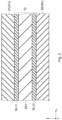
- Fig. 3 is a schematic partial cross-sectional view of an area III shown in Fig. 2 .
- the floor pan 10 is composed of a resin-coated steel plate.
- the upper surface of a steel plate SS1 is coated with a resin layer (first resin layer) RL11, and a part of the lower surface of the steel plate SS1 that is in contact with the lower surface-side reinforcing member (lower-side floor side member 30) is coated with another resin layer (second resin layer) RL12. That is, as shown in Figs.
- the resin layer RL11 is formed on the surface of the floor pan 10 in contact with the upper surface-side reinforcing member (upper-side floor side member 21 and the like). Further, the resin layer RL12 is formed on the part of the surface of the floor pan 10 that is in contact with the lower surface-side reinforcing member (lower-side floor side member 30).
- the floor pan 10 is formed of a resin-coated steel plate as shown in Fig. 2 . Further, the resin layer RL11 is formed on the part of the surface of the floor pan 10 that is in contact with the upper surface-side reinforcing member (upper-side floor side member 21 and the like). Further, the resin layer RL12 is formed on the part of the surface of the floor pan 10 that is in contact with the lower surface-side reinforcing member (lower-side floor side member 30).
- a flow channel (a joggle structure) was formed inside the flange part of the upper-side floor side member and/or the lower-side floor side member in order to feed an electropainting liquid.
- the floor pan 10 is composed of a resin-coated steel plate, there is no need to provide a joggle structure in the flange part 21c of the upper-side floor side member 21 or the flange part 30c of the lower-side floor side member 30. Therefore, the entire flange part 21c of the upper-side floor side member 21 and the flange part 30c of the lower-side floor side member 30 can be formed in a flat shape. That is, for the structures of the upper-side floor side member 21 and the lower-side floor side member 30 are simplified, and therefore the manufacturing costs can be reduced.
- the steel plate SS1 is composed of, but is not particularly limited to, ordinary steel or steel containing an additive element(s) such as chromium. Further, a plating film may be provided on the surface of the steel plate SS1 in order to enhance the rust-prevention property. That is, the steel plate SS1 may be a plated steel plate. Examples of the plating film include, but are not particularly limited to, a plating film containing any one of metallic elements such as zinc, aluminum, cobalt, tin and nickel, and an alloy plating film containing at least one of these metallic elements.
- the resin layers RL11 and RL12 are composed of, but are not particularly limited to, an organic resin such as a water-based coating composition or an organic solvent-based coating composition.
- organic resin include polyurethane resins, polyester resins, epoxy resins, (meth)acrylic resins, polyolefin resins, denatured resins thereof, and mixtures thereof.
- the organic resin contains, for example, a rust-prevention pigment and has a rust-prevention property.
- the rustproof pigment contains, but are not limited to, fine particles of at least one of, for example, a silicate compound, a phosphate compound, a vanadate compound, and a metal oxide.
- the rustproof pigment is, for example, nanoparticles having a volume-average diameter of about 1 to 50 nm, fine particles having a volume-average diameter of about 0.5 to 10 ⁇ m, or a mixture of them.
- the amount of the rust-prevention pigment added in the resin layers RL1 and RL2 may be, for example, 1 to 40 volume% or 2 to 20 volume%.
- the organic resin may contain, for example, a conductive pigment and hence may be conductive.
- the conductive pigments include, but are not particularly limited to, fine particles of at least one of, for example, a metal, an alloy, conductive carbon, iron phosphide, a carbide, and a semiconductor oxide.
- the volume-average diameter of the fine particles is, for example, about 0.5 to 10 ⁇ m.
- the amount of the added conductive pigment in the resin layers RL1 and RL2 may be, for example, 1 to 40 volume% or 2 to 20 volume%.
- the thickness of the resin layers RL1 and RL2 is, for example, 0.5 to 10 ⁇ m. Since the thickness of the resin layers RL1 and RL2 is 0.5 ⁇ m or larger, a corrosion resistance can be obtained, and since the thickness of the resin layers RL1 and RL2 is 10 ⁇ m or smaller, destruction or delamination of the resin layers RL1 and RL2 can be suppressed during the press forming and the like.
- the thickness of the resin layers RL1 and RL2 may be, for example, 1 to 5 ⁇ m.
- the thicknesses of the resin layers RL11 and RL12 are, for example, roughly equal to each other.
- the thickness of the resin layer RL11 formed on the upper surface of the floor pan 10 may be larger than that of the resin layer RL12 formed on the lower surface of the floor pan 10. The corrosion of floor pan 10, which would otherwise be caused by a snow-melting agent, can be suppressed more effectively.
- an undercoating film may be provided between the resin layer RL11 and the surface of the steel plate SS1 and between the resin layer RL12 and the surface of the steel plate SS1.
- the number of layers and the composition of the undercoating film are not limited to any particular numbers and any particular compositions.
- a resin layer may be formed on the end face of the steel plate SS1.
- the floor pan 10 is formed of a resin-coated steel plate. Note that a resin layer of this resin-coated steel plate is formed on the upper surface of the floor pan 10 and on the part of the lower layer of the floor pan 10 that is in contact with the lower surface-side reinforcing member (lower-side floor side member 30).
- At least one of the upper surface-side reinforcing member (upper-side floor side member 21 and the like) and the lower surface-side reinforcing member (lower-side floor side member 30) may be formed of a resin-coated steel plate.
- manufacturing costs can be reduced by forming only the floor pan 10 from a resin-coated steel plate, and forming each of the upper surface-side and lower surface-side reinforcing members from an ordinary steel plate coated with no resin.
- the resin layer RL12 may be formed over the entire lower surface of the floor pan 10. However, as shown in Fig. 2 , manufacturing costs can be reduced by forming the resin layer RL12 only on a part of the surface of the floor pan 10 located in the vicinity of the part thereof that is in contact with the lower surface-side reinforcing member (lower-side floor side member 30), i.e., only on a part of the surface of the floor pan 10 including the part thereof that is in contact with the lower surface-side reinforcing member (lower-side floor side member 30).
- the floor pan 10 is formed of, for example, a resin-coated steel plate (first resin-coated steel plate) 10a in which the resin layer RL11 is formed only on the upper surface, and a resin-coated steel plate (second resin-coated steel plate) 10b in which the resin layers RL11 and RL12 are formed on the upper and lower surfaces. That is, the floor pan 10 may be formed of a tailored blank material in which the resin-coated steel plates 10a and 10b are welded to each other. Note that the types and thicknesses of the steel plates SS1 of which the resin-coated steel plates 10a and 10b are respectively formed may be the same as each other or different from each other. Further, the types and thicknesses of the resin layer RL11 of the resin-coated steel plate 10a and the resin layer RL11 of the resin-coated steel plate 10b may be the same as each other or different from each other.
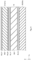
- Fig. 4 is a schematic cross-sectional view of the vehicle floor structure according to the second embodiment.
- Fig. 4 is a cross section corresponding to that shown in Fig. 3 .
- the vehicle floor structure according to this embodiment has a structure similar to that of the vehicle floor structure according to the first embodiment shown in Fig. 1 .
- the upper surface-side reinforcing member (upper-side floor side member 21 and the like), in addition to the floor pan 10, is also formed of a resin-coated steel plate.
- the upper surface of the steel plate SS2 is coated with a resin layer RL21 and the entire lower surface of the steel plate SS2 is coated with a resin layer RL22.
- the steel plate SS2 is a steel plate similar to the steel plate SS1, and the resin layers RL21 and RL22 are resin layers similar to the resin layers RL11 and RL12.
- the thicknesses of the resin layers RL21 and RL22 are, for example, roughly equal to each other. Further, the thicknesses of the resin layers RL21 and RL22 may be smaller than those of the resin layers RL11 and RL12 of the floor pan 10. By the above-described structure, the manufacturing costs can be reduced.
- the thickness of the resin layer RL21 on the upper surface may be larger than that of the resin layer RL22 on the lower surface. Further, only the resin layer RL21 on the upper surface may be formed and the resin layer RL22 on the lower surface may not be formed.
- the rest of the configuration is similar to that of the vehicle floor structure according to the first embodiment, and therefore the description thereof is omitted.
- Fig. 5 is a schematic cross-sectional view of the vehicle floor structure according to the third embodiment.
- Fig. 5 is a cross section corresponding to that shown in Fig. 3 .
- the vehicle floor structure according to this embodiment has a structure similar to that of the vehicle floor structure according to the first embodiment shown in Fig. 1 .
- the lower surface-side reinforcing member (lower-side floor side member 30), in addition to the floor pan 10, is also formed of a resin-coated steel plate.
- the upper surface of the steel plate SS3 is coated with a resin layer RL31 and the entire lower surface of the steel plate SS3 is coated with a resin layer RL32.
- the steel plate SS3 is a steel plate similar to the steel plate SS1, and the resin layers RL31 and RL32 are resin layers similar to the resin layers RL11 and RL12.
- the thicknesses of the resin layers RL31 and RL32 are, for example, roughly equal to each other. Further, the thicknesses of the resin layer RL31 and RL32 may be smaller than those of the resin layers RL11 and RL12 of the floor pan 10. By the above-described structure, the manufacturing costs can be reduced.
- the thickness of the resin layer RL32 on the lower surface may be larger than that of the resin layer RL31 on the upper surface. Further, only the resin layer RL32 on the lower surface may be formed and the resin layer RL31 on the upper surface may not be formed.
- the rest of the configuration is similar to that of the vehicle floor structure according to the first embodiment, and therefore the description thereof is omitted.
- both the upper surface-side reinforcing member (upper-side floor side member 21 and the like) and the lower surface-side reinforcing member (lower-side floor side member 30), in addition to the floor pan 10, may be formed of resin-coated steel plates.
Landscapes
- Engineering & Computer Science (AREA)
- Chemical & Material Sciences (AREA)
- Combustion & Propulsion (AREA)
- Transportation (AREA)
- Mechanical Engineering (AREA)
- Architecture (AREA)
- Structural Engineering (AREA)
- Body Structure For Vehicles (AREA)
Abstract
Description
- The present disclosure relates to a vehicle floor structure and a method for manufacturing a vehicle.
- As disclosed in
Japanese Unexamined Patent Application Publication No. 2015-202686 - However, resin-coated steel plates are more expensive than ordinary steel plates, so parts in automobiles in which resin-coated steel plates are used need to be carefully chosen.
- It should be noted that a vehicle floor structure is composed of a floor pan (also called a "floor panel") and reinforcing members such as a floor cross member and a floor side member joined to the floor pan. Note that since the contact surfaces in the joint (e.g., the surfaces in the joint on which the reinforcing members are in contact with the floor pan) are not electropainted, there is a problem that moisture may enter the gap between the contact surfaces of the joint and rust may occur.
- Meanwhile, the inventors found that the surface of the floor pan positioned inside the vehicle was corroded by, for example, a snow-melting agent adhering to the occupants' shoes.
- In view of these circumstances, the present disclosure provides a vehicle floor structure that can suppress corrosion in the contact surfaces between a floor pan and an upper surface-side reinforcing member and between the floor pan and a lower surface-side reinforcing member, and also suppress corrosion of the upper surface in the floor pan, which would otherwise be caused by a snow-melting agent.
- A first exemplary aspect is a vehicle floor structure including:
- a floor pan;
- an upper surface-side reinforcing member joined to an upper surface of the floor pan; and
- a lower surface-side reinforcing member joined to a lower surface of the floor pan, in which
- the floor pan is formed of a resin-coated steel plate, and a resin layer of the resin-coated steel plate includes a first resin layer formed on the upper surface of the floor pan and a second resin layer formed on a part of the lower surface of the floor pan that is in contact with the lower surface-side reinforcing member.
- In the vehicle floor structure according to an aspect of the present disclosure, the floor pan is formed of a resin-coated steel plate, and a resin layer of the resin-coated steel plate includes a first resin layer formed on the upper surface of the floor pan and a second resin layer formed on a part of the lower surface of the floor pan that is in contact with the lower surface-side reinforcing member. Therefore, corrosion on the contact surfaces between the floor pan and the upper surface-side reinforcing member and between the floor pan and the lower surface-side reinforcing member can be suppressed, and corrosion of the upper surface in the floor pan, which would otherwise be caused by a snow-melting agent, can also be suppressed.
- The first resin layer may be formed over the entire upper surface of the floor pan, and the second resin layer may be formed only on a part of the lower surface of the floor pan including the part of the surface thereof in contact with the lower surface-side reinforcing member.
- Note that the floor pan may be formed of a tailored blank material in which a first resin-coated steel plate in which only the first resin layer is formed and a second resin-coated steel plate in which the first and second resin layers are formed are welded to each other.
- The upper surface-side reinforcing member may be formed of a resin-coated steel plate, and a thickness of a resin layer of the resin-coated steel plate of which the upper surface-side reinforcing member is formed may be smaller than that of the resin layer of the resin-coated steel plate of which the floor pan is formed.
- Further, the lower surface-side reinforcing member may be formed of a resin-coated steel plate, and a thickness of a resin layer of the resin-coated steel plate of which the lower surface-side reinforcing member is formed may be smaller than that of the resin layer of the resin-coated steel plate of which the floor pan is formed.
- Meanwhile, each of the upper surface-side and lower surface-side reinforcing members may be formed of a steel plate coated with no resin.
- Further, a thickness of the resin layer formed on the upper surface of the floor pan may be larger than that of the resin layer formed on the lower surface of the floor pan.
- By the above-described structure, it is possible to reduce production costs as well as suppressing corrosion.
- Each of the upper surface-side and lower surface-side reinforcing members may have a hat-like shape in cross section perpendicular to a longitudinal direction thereof and may be joined to the floor pan at a pair of flange parts extending in the longitudinal direction.
- Note that outer peripheries of the pair of flange parts joined to the floor pan may not be coated with any rust-prevention sealer.
- Further, an overall shape of the flange parts may be flat.
- Another exemplary aspect is a method for manufacturing a vehicle, including electropainting a floor pan together with an upper surface-side reinforcing member and a lower surface-side reinforcing member, the upper surface-side reinforcing member being joined to an upper surface of the floor pan, and the lower surface-side reinforcing member being joined to a lower surface of the floor pan, in which
the floor pan is formed of a resin-coated steel plate, and a resin layer of the resin-coated steel plate is formed on the upper surface of the floor pan, and on a part of the lower surface of the floor pan that is in contact with the lower surface-side reinforcing member. - In the method for manufacturing a vehicle according to an aspect of the present disclosure, the floor pan is formed of a resin-coated steel plate, and a resin layer of the resin-coated steel plate is formed on the upper surface of the floor pan, and on a part of the lower surface of the floor pan that is in contact with the lower surface-side reinforcing member. Therefore, corrosion on the contact surfaces between the floor pan and the upper surface-side reinforcing member and between the floor pan and the lower surface-side reinforcing member can be suppressed, and corrosion of the upper surface in the floor pan, which would otherwise be caused by a snow-melting agent, can also be suppressed.
- According to the present disclosure, it is possible to provide a vehicle floor structure capable of suppressing corrosion in the contact surfaces between a floor pan and an upper surface-side reinforcing member and between the floor pan and a lower surface-side reinforcing member, and also suppressing corrosion of the upper surface in the floor pan, which would otherwise be caused by a snow-melting agent.
- The above and other objects, features and advantages of the present disclosure will become more fully understood from the detailed description given hereinbelow and the accompanying drawings which are given by way of illustration only, and thus are not to be considered as limiting the present disclosure.
-
-
Fig. 1 is a schematic cross-sectional view of a vehicle floor structure according to a first embodiment; -
Fig. 2 is a schematic partial cross-sectional view of an area II shown inFig. 1 ; -
Fig. 3 is a schematic partial cross-sectional view of an area III shown inFig. 2 ; -
Fig. 4 is a schematic partial cross-sectional view of a vehicle floor structure according to a second embodiment; and -
Fig. 5 is a schematic partial cross-sectional view of a vehicle floor structure according to a third embodiment. - Specific embodiments to which the present disclosure is applied will be described hereafter in detail with reference to the drawings. However, the present disclosure is not particularly limited to the following embodiments. Further, the following descriptions and drawings have been simplified as appropriate for clarifying the explanation.
- Firstly, a structure of a vehicle floor structure according to a first embodiment will be described with reference to
Fig. 1. Fig. 1 is a schematic cross-sectional view of a vehicle floor structure according to the first embodiment. - As shown in
Fig. 1 , the vehicle floor structure according to this embodiment includes afloor pan 10, an upper-sidefloor side member 21, a tunnel-side frame 22, afloor cross member 23, and a lower-sidefloor side member 30. - Note that the upper-side
floor side member 21, the tunnel-side frame 22, and thefloor cross member 23 constitutes an upper surface-side reinforcing member joined to the upper surface (vehicle interior-side surface) of thefloor pan 10. Meanwhile, the lower-sidefloor side member 30 is an upper surface-side reinforcing member joined to the lower surface (vehicle exterior-side surface) of thefloor pan 10. - Naturally, the right-handed xyz-orthogonal coordinate system shown in
Fig. 1 and other figures are common throughout the drawings, and they are just for convenience in explaining the positional relationships among components. In the example shown in the drawings, the x-axis positive direction indicates the vehicle forward direction; the y-axis direction indicates the vehicle width direction; and the z-axis positive direction indicates the vertical upward direction. - Further, the vehicle floor structure according to this embodiment has a left-right symmetrical structure when viewed from the front of the vehicle (x-axis positive direction), and only the left half of the vehicle floor structure is shown in
Fig. 1 . - Further, the vehicle floor structure according to this embodiment only needs to include at least one upper surface-side reinforcing member joined to the upper surface of the
floor pan 10 and one lower surface-side reinforcing member joined to the lower surface of thefloor pan 10. The upper surface-side reinforcing member and lower surface-side reinforcing member are not particularly limited to those shown inFig. 1 . - The
floor pan 10 is a plate-like steel plate member that constitutes the main part of the vehicle floor structure. As shown inFig. 1 , thefloor pan 10 includes afloor tunnel 11 at the center in the vehicle width direction (y-axis direction), which extends in the vehicle front/rear direction (x-axis direction) and extends upward in a tunnel-like shape from the flat part. - At each of both ends in the vehicle width direction (y-axis direction) of the
floor pan 10, aflange part 12 rising upward from the flat part. Theflange part 12 is joined, for example, to a side sill (not shown). - The
floor pan 10 is press-formed from, for example, one steel plate. - The upper-side
floor side member 21 is an upper surface-side reinforcing member joined to the upper surface of thefloor pan 10. As shown inFig. 1 , the upper-sidefloor side member 21 extends, for example, in the vehicle front/rear direction (x-axis direction) in a middle part of thefloor pan 10 between thefloor tunnel 11 and theflange part 12. - Note that
Fig. 2 is a schematic partial cross-sectional view of an area II shown inFig. 1 . As shown inFig. 2 , the upper-sidefloor side member 21 is a steel plate member having a hat-like shape in cross section perpendicular to the longitudinal direction (x-axis direction). That is, the upper-sidefloor side member 21 includes atop plate 21a, a pair ofsidewalls 21b, and a pair offlange parts 21c. - Note that these parts in the upper-side
floor side member 21 have been defined just for explanatory purposes. Further, the structure of the upper-sidefloor side member 21 is not particularly limited to the examples shown inFigs. 1 and2 . - More specifically, a pair of
sidewalls 21b is formed downward from the end in the width direction (y-axis) of thetop plate 21a extending in the vehicle front/rear direction (x-axis direction). Further, aflange part 21c protrudes outward from the lower end of each of the sidewalls 21b. The upper-sidefloor side member 21 is press-formed from, for example, one steel plate. - As shown in
Fig. 2 , a pair offlange parts 21c of the upper-sidefloor side member 21 are joined to the upper surface of the flat part of thefloor pan 10 by welding, screwing, etc. Theentire flange part 21c is formed in a flat shape, and the upper-sidefloor side member 21 has a simple structure. - The tunnel-
side frame 22 is an upper surface-side reinforcing member joined to the upper surface of thefloor pan 10. As shown inFig. 1 , the tunnel-side frame 22 extends in the vehicle front/rear direction (x-axis direction) from the flat part of thefloor pan 10 to the sidewall of thefloor tunnel 11. That is, the tunnel-side frame 22 reinforces thefloor tunnel 11 in thefloor pan 10. - More specifically, as shown in
Fig. 1 , the tunnel-side frame 22 includes an L-shaped main part of which the cross-sectional shape is perpendicular to the longitudinal (x-axis) direction, and a pair of flange parts protruding from both ends in the vehicle width direction (y-axis) of the main part. As shown inFig. 1 , one of the flange parts of the tunnel-side frame 22 is joined to the flat part of thefloor pan 10, and the other flange part of the tunnel-side frame 22 is joined to the sidewall of thefloor tunnel 11 of thefloor pan 10. - The
floor cross member 23 is an upper surface-side reinforcing member joined to the upper surface of thefloor pan 10. As shown inFig. 1 , thefloor cross member 23 extends from theflange part 12 of thefloor pan 10 to the tunnel-side frame 22 in the vehicle width direction (y-axis direction). - More specifically, the
floor cross member 23, like the upper-sidefloor side member 21, is a steel plate member having a hat-like shape in cross section perpendicular to the longitudinal direction (y-axis direction). That is, thefloor cross member 23 includes a top plate, a pair of sidewalls, and a pair of flange parts. The flange part of thefloor cross member 23 is joined to the upper surface of the main part of thefloor pan 10 by welding, screwing, etc. The entire flange part of thefloor cross member 23 is formed in a flat shape, and thefloor cross member 23 has a simple structure. - The
floor cross member 23 is press-formed from, for example, one steel plate. - The lower-side
floor side member 30 is a lower surface-side reinforcing member joined to the lower surface of thefloor pan 10. As shown inFig. 1 , the lower-sidefloor side member 30 extends, for example, in the vehicle front/rear direction (x-axis direction) in a middle part of thefloor pan 10 between thefloor tunnel 11 and theflange part 12. Note that the lower-sidefloor side member 30 is opposed to the upper-sidefloor side member 21 with thefloor pan 10 interposed therebetween. Note that the lower-sidefloor side member 30 may be displaced (i.e., shifted) in the vehicle width direction (y-axis direction) with respect to the upper-sidefloor side member 21. - As shown in
Fig. 2 , the lower-sidefloor side member 30 has a shape identical to the vertically-reversed shape of the upper-sidefloor side member 21, and is a steel plate member having a hat-like shape in cross section perpendicular to the longitudinal direction (x-axis direction). That is, the lower-sidefloor side member 30 includes abottom plate 30a, a pair ofsidewalls 30b, and a pair offlange parts 30c. Note that thebottom plate 30a of the lower-sidefloor side member 30 corresponds totop plate 21a of the upper-sidefloor side member 21. - More specifically, a pair of
sidewalls 30b is formed upward from the end in the width direction (y-axis) of thebottom plate 30a extending in the vehicle front/rear direction (x-axis). Further, aflange part 30c protrudes outward from the upper end of each of the sidewalls 30b. The lower-sidefloor side member 30 is press-formed from, for example, one steel plate. - As shown in
Fig. 2 , a pair offlange parts 30c of the lower-sidefloor side member 30 are joined to the lower surface of the flat part of thefloor pan 10 by welding, screwing, etc. Theentire flange part 30c is formed in a flat shape, and the lower-sidefloor side member 30 has a simple structure. - Note that in the vehicle floor structure according to this embodiment, the upper surface-side reinforcing member (upper-side
floor side member 21 and the like) is joined to the upper surface of thefloor pan 10, and the lower surface-side reinforcing member (lower-side floor side member 30) is joined to the lower surface of thefloor pan 10. Then, thefloor pan 10 to which the upper surface-side and lower surface-side reinforcing members are joined, i.e., the vehicle floor structure according to this embodiment, is electropainted. After the electropainting, the vehicle floor structure may be further painted, for example, for intermediate and top coatings. - Note that
Fig. 3 is a schematic partial cross-sectional view of an area III shown inFig. 2 . As shown inFigs. 2 and3 , thefloor pan 10 is composed of a resin-coated steel plate. In thefloor pan 10, the upper surface of a steel plate SS1 is coated with a resin layer (first resin layer) RL11, and a part of the lower surface of the steel plate SS1 that is in contact with the lower surface-side reinforcing member (lower-side floor side member 30) is coated with another resin layer (second resin layer) RL12. That is, as shown inFigs. 2 and3 , the resin layer RL11 is formed on the surface of thefloor pan 10 in contact with the upper surface-side reinforcing member (upper-sidefloor side member 21 and the like). Further, the resin layer RL12 is formed on the part of the surface of thefloor pan 10 that is in contact with the lower surface-side reinforcing member (lower-side floor side member 30). - As described above, in the related art, when a floor pan to which upper surface-side and lower surface-side reinforcing members are joined is electropainted, the contact surfaces between the upper surface-side and lower surface-side reinforcing members and the floor pan cannot be electropainted, and therefore there is a risk of the occurrence of corrosion. Therefore, it was necessary to apply a rust-prevention sealer to the boundary line between the floor pan and the upper surface-side and lower surface-side reinforcing members, i.e., to the outer periphery of the flange part of the upper surface-side and lower surface-side reinforcing members along which the upper surface-side and lower surface-side reinforcing members are joined to the floor pan along.
- In contrast to this, in the vehicle floor structure according to this embodiment, the
floor pan 10 is formed of a resin-coated steel plate as shown inFig. 2 . Further, the resin layer RL11 is formed on the part of the surface of thefloor pan 10 that is in contact with the upper surface-side reinforcing member (upper-sidefloor side member 21 and the like). Further, the resin layer RL12 is formed on the part of the surface of thefloor pan 10 that is in contact with the lower surface-side reinforcing member (lower-side floor side member 30). - Therefore, owing to the resin layer RL11, corrosion causing substances such as water, oxygen, and chlorine hardly reach the steel plate SS1 of the
floor pan 10 and the upper surface-side reinforcing member (upper-sidefloor side member 21 and the like) which is formed of a steel plate(s). Similarly, owing to the resin layer RL12, corrosion causing substances hardly reach the steel plate SS1 of thefloor pan 10 and the lower surface-side reinforcing member (lower-side floor side member 30) which is formed of a steel plate. Therefore, corrosion in the contact surfaces between the upper surface-side reinforcing member and thefloor pan 10 and between the lower-sidefloor side member 30 and thefloor pan 10 can be suppressed. - As a result, there is no need to apply a rust-prevention sealer on the boundary line between the
floor pan 10 and the flange part of the upper surface-side reinforcing member (such asflange part 21c and the like of the upper-side floor side member 21), i.e., to the outer periphery of the flange part. Similarly, there is no need to apply a rust-prevention sealer on the boundary line between thefloor pan 10 and the flange part of the lower surface-side reinforcing member (such asflange part 30c and the like of the lower-side floor side member 30), i.e., to the outer periphery of the flange part. - Further, in the vehicle floor structure in the related art, a flow channel (a joggle structure) was formed inside the flange part of the upper-side floor side member and/or the lower-side floor side member in order to feed an electropainting liquid. In contrast to this, in the vehicle floor structure according to this embodiment, since the
floor pan 10 is composed of a resin-coated steel plate, there is no need to provide a joggle structure in theflange part 21c of the upper-sidefloor side member 21 or theflange part 30c of the lower-sidefloor side member 30. Therefore, theentire flange part 21c of the upper-sidefloor side member 21 and theflange part 30c of the lower-sidefloor side member 30 can be formed in a flat shape. That is, for the structures of the upper-sidefloor side member 21 and the lower-sidefloor side member 30 are simplified, and therefore the manufacturing costs can be reduced. - Further, since substantially the entire upper surface of the steel plate SS1 in the
floor pan 10 is coated with the resin layer RL11, corrosion of thefloor pan 10, which would otherwise be caused by, for example, a snow-melting agent adhering to the occupants' shoes, can also be suppressed. - Note that, as described later, when the resin layers RL11 and RL12 contain a rust-prevention pigment, the corrosion can be further suppressed.
- Note that the steel plate SS1 is composed of, but is not particularly limited to, ordinary steel or steel containing an additive element(s) such as chromium. Further, a plating film may be provided on the surface of the steel plate SS1 in order to enhance the rust-prevention property. That is, the steel plate SS1 may be a plated steel plate. Examples of the plating film include, but are not particularly limited to, a plating film containing any one of metallic elements such as zinc, aluminum, cobalt, tin and nickel, and an alloy plating film containing at least one of these metallic elements.
- Further, the resin layers RL11 and RL12 are composed of, but are not particularly limited to, an organic resin such as a water-based coating composition or an organic solvent-based coating composition. Examples of the organic resin include polyurethane resins, polyester resins, epoxy resins, (meth)acrylic resins, polyolefin resins, denatured resins thereof, and mixtures thereof.
- The organic resin contains, for example, a rust-prevention pigment and has a rust-prevention property. The rustproof pigment contains, but are not limited to, fine particles of at least one of, for example, a silicate compound, a phosphate compound, a vanadate compound, and a metal oxide. The rustproof pigment is, for example, nanoparticles having a volume-average diameter of about 1 to 50 nm, fine particles having a volume-average diameter of about 0.5 to 10 µm, or a mixture of them. The amount of the rust-prevention pigment added in the resin layers RL1 and RL2 may be, for example, 1 to 40 volume% or 2 to 20 volume%.
- Further, the organic resin may contain, for example, a conductive pigment and hence may be conductive. The conductive pigments include, but are not particularly limited to, fine particles of at least one of, for example, a metal, an alloy, conductive carbon, iron phosphide, a carbide, and a semiconductor oxide. The volume-average diameter of the fine particles is, for example, about 0.5 to 10 µm. The amount of the added conductive pigment in the resin layers RL1 and RL2 may be, for example, 1 to 40 volume% or 2 to 20 volume%.
- The thickness of the resin layers RL1 and RL2 is, for example, 0.5 to 10 µm. Since the thickness of the resin layers RL1 and RL2 is 0.5 µm or larger, a corrosion resistance can be obtained, and since the thickness of the resin layers RL1 and RL2 is 10 µm or smaller, destruction or delamination of the resin layers RL1 and RL2 can be suppressed during the press forming and the like. The thickness of the resin layers RL1 and RL2 may be, for example, 1 to 5 µm.
- Further, the thicknesses of the resin layers RL11 and RL12 are, for example, roughly equal to each other. However, the thickness of the resin layer RL11 formed on the upper surface of the
floor pan 10 may be larger than that of the resin layer RL12 formed on the lower surface of thefloor pan 10. The corrosion offloor pan 10, which would otherwise be caused by a snow-melting agent, can be suppressed more effectively. - Note that in order to improve the adhesion of the resin layer RL11 to the steel plate SS1 and of the resin layer RL12 to the steel plate SS1, the corrosion resistance, and the like, an undercoating film may be provided between the resin layer RL11 and the surface of the steel plate SS1 and between the resin layer RL12 and the surface of the steel plate SS1. The number of layers and the composition of the undercoating film are not limited to any particular numbers and any particular compositions.
- Further, in the
floor pan 10 according to this embodiment, although no resin layer is formed on the end face of the steel plate SS1, a resin layer may be formed on the end face of the steel plate SS1. - As explained above, in the vehicle floor structure according to this embodiment, the
floor pan 10 is formed of a resin-coated steel plate. Note that a resin layer of this resin-coated steel plate is formed on the upper surface of thefloor pan 10 and on the part of the lower layer of thefloor pan 10 that is in contact with the lower surface-side reinforcing member (lower-side floor side member 30). Therefore, corrosion in the contact surfaces between thefloor pan 10 and the upper surface-side reinforcing member (upper-sidefloor side member 21 and the like) and between thefloor pan 10 and the lower surface-side reinforcing member (lower-side floor side member 30) can be suppressed, and corrosion of the upper surface of thefloor pan 10, which would otherwise be caused by a snow-melting agent, can also be suppressed. - Note that, as described later, at least one of the upper surface-side reinforcing member (upper-side
floor side member 21 and the like) and the lower surface-side reinforcing member (lower-side floor side member 30) may be formed of a resin-coated steel plate. - However, as shown in
Fig. 2 , manufacturing costs can be reduced by forming only thefloor pan 10 from a resin-coated steel plate, and forming each of the upper surface-side and lower surface-side reinforcing members from an ordinary steel plate coated with no resin. - Further, the resin layer RL12 may be formed over the entire lower surface of the
floor pan 10. However, as shown inFig. 2 , manufacturing costs can be reduced by forming the resin layer RL12 only on a part of the surface of thefloor pan 10 located in the vicinity of the part thereof that is in contact with the lower surface-side reinforcing member (lower-side floor side member 30), i.e., only on a part of the surface of thefloor pan 10 including the part thereof that is in contact with the lower surface-side reinforcing member (lower-side floor side member 30). - As shown in
Fig. 2 , thefloor pan 10 is formed of, for example, a resin-coated steel plate (first resin-coated steel plate) 10a in which the resin layer RL11 is formed only on the upper surface, and a resin-coated steel plate (second resin-coated steel plate) 10b in which the resin layers RL11 and RL12 are formed on the upper and lower surfaces. That is, thefloor pan 10 may be formed of a tailored blank material in which the resin-coatedsteel plates steel plates steel plate 10a and the resin layer RL11 of the resin-coatedsteel plate 10b may be the same as each other or different from each other. - Next, a structure of a vehicle floor structure according to a second embodiment will be described with reference to
Fig. 4. Fig. 4 is a schematic cross-sectional view of the vehicle floor structure according to the second embodiment.Fig. 4 is a cross section corresponding to that shown inFig. 3 . - The vehicle floor structure according to this embodiment has a structure similar to that of the vehicle floor structure according to the first embodiment shown in
Fig. 1 . - As shown in
Fig. 4 , in the vehicle floor structure according to this embodiment, the upper surface-side reinforcing member (upper-sidefloor side member 21 and the like), in addition to thefloor pan 10, is also formed of a resin-coated steel plate. In the upper-sidefloor side member 21 shown inFig. 4 , the upper surface of the steel plate SS2 is coated with a resin layer RL21 and the entire lower surface of the steel plate SS2 is coated with a resin layer RL22. - The steel plate SS2 is a steel plate similar to the steel plate SS1, and the resin layers RL21 and RL22 are resin layers similar to the resin layers RL11 and RL12.
- Owing to the resin layer RL21, corrosion of the upper surface of the upper-side
floor side member 21, which would otherwise be caused by a snow-melting agent, can be suppressed. - Owing to the resin layer RL22, corrosion on the contact surface between the upper-side
floor side member 21 and thefloor pan 10 can be further suppressed. - As shown in
Fig. 4 , the thicknesses of the resin layers RL21 and RL22 are, for example, roughly equal to each other. Further, the thicknesses of the resin layers RL21 and RL22 may be smaller than those of the resin layers RL11 and RL12 of thefloor pan 10. By the above-described structure, the manufacturing costs can be reduced. - Further, the thickness of the resin layer RL21 on the upper surface may be larger than that of the resin layer RL22 on the lower surface. Further, only the resin layer RL21 on the upper surface may be formed and the resin layer RL22 on the lower surface may not be formed. By the above-described structure, the manufacturing costs can be reduced.
- The rest of the configuration is similar to that of the vehicle floor structure according to the first embodiment, and therefore the description thereof is omitted.
- Next, a structure of a vehicle floor structure according to a third embodiment will be described with reference to
Fig. 5. Fig. 5 is a schematic cross-sectional view of the vehicle floor structure according to the third embodiment.Fig. 5 is a cross section corresponding to that shown inFig. 3 . - The vehicle floor structure according to this embodiment has a structure similar to that of the vehicle floor structure according to the first embodiment shown in
Fig. 1 . - As shown in
Fig. 5 , in the vehicle floor structure according to this embodiment, the lower surface-side reinforcing member (lower-side floor side member 30), in addition to thefloor pan 10, is also formed of a resin-coated steel plate. In the lower-sidefloor side member 30 shown inFig. 5 , the upper surface of the steel plate SS3 is coated with a resin layer RL31 and the entire lower surface of the steel plate SS3 is coated with a resin layer RL32. - The steel plate SS3 is a steel plate similar to the steel plate SS1, and the resin layers RL31 and RL32 are resin layers similar to the resin layers RL11 and RL12.
- Owing to the resin layer RL31, corrosion on the contact surface between the lower-side
floor side member 30 and thefloor pan 10 can be further suppressed. - Owing to the resin layer RL32, corrosion of the lower surface of the lower-side
floor side member 30 can be suppressed. - As shown in
Fig. 5 , the thicknesses of the resin layers RL31 and RL32 are, for example, roughly equal to each other. Further, the thicknesses of the resin layer RL31 and RL32 may be smaller than those of the resin layers RL11 and RL12 of thefloor pan 10. By the above-described structure, the manufacturing costs can be reduced. - Further, the thickness of the resin layer RL32 on the lower surface may be larger than that of the resin layer RL31 on the upper surface. Further, only the resin layer RL32 on the lower surface may be formed and the resin layer RL31 on the upper surface may not be formed. By the above-described structure, the manufacturing costs can be reduced.
- The rest of the configuration is similar to that of the vehicle floor structure according to the first embodiment, and therefore the description thereof is omitted.
- Note that this embodiment can be combined with the second embodiment. That is, both the upper surface-side reinforcing member (upper-side
floor side member 21 and the like) and the lower surface-side reinforcing member (lower-side floor side member 30), in addition to thefloor pan 10, may be formed of resin-coated steel plates. - From the disclosure thus described, it will be obvious that the embodiments of the disclosure may be varied in many ways. Such variations are not to be regarded as a departure from the spirit and scope of the disclosure, and all such modifications as would be obvious to one skilled in the art are intended for inclusion within the scope of the following claims.
Claims (11)
- A vehicle floor structure comprising:a floor pan (10);an upper surface-side reinforcing member (21) joined to an upper surface of the floor pan (10); anda lower surface-side reinforcing member (30) joined to a lower surface of the floor pan (10), whereinthe floor pan (10) is formed of a resin-coated steel plate, anda resin layer of the resin-coated steel plate includes a first resin layer (RL11) formed on the upper surface of the floor pan (10) and a second resin layer (RL12) formed on a part of the lower surface of the floor pan (10) that is in contact with the lower surface-side reinforcing member (30).
- The vehicle floor structure according to Claim 1, whereinthe first resin layer (RL11) is formed over the entire upper surface of the floor pan (10), andthe second resin layer (RL12) is formed only on a part of the lower surface of the floor pan (10) including the part of the surface thereof in contact with the lower surface-side reinforcing member (30).
- The vehicle floor structure according to Claim 2, wherein the floor pan (10) is formed of a tailored blank material in which a first resin-coated steel plate in which only the first resin layer (RL11) is formed and a second resin-coated steel plate in which the first and second resin layers (RL11, RL12) are formed are welded to each other.
- The vehicle floor structure according to any one of Claims 1 to 3, whereinthe upper surface-side reinforcing member (21) is formed of a resin-coated steel plate, anda thickness of a resin layer of the resin-coated steel plate of which the upper surface-side reinforcing member (21) is formed is smaller than that of the first resin layer (RL11) of the floor pan (10).
- The vehicle floor structure according to any one of Claims 1 to 4, whereinthe lower surface-side reinforcing member (30) is formed of a resin-coated steel plate, anda thickness of a resin layer of the resin-coated steel plate of which the lower surface-side reinforcing member (30) is formed is smaller than that of the second resin layer (RL12) of the floor pan (10).
- The vehicle floor structure according to any one of Claims 1 to 3, wherein each of the upper surface-side and lower surface-side reinforcing members (21, 30) is formed of a steel plate coated with no resin.
- The vehicle floor structure according to any one of Claims 1 to 6, wherein a thickness of the first resin layer (RL11) is larger than that of the second resin layer (RL12).
- The vehicle floor structure according to any one of Claims 1 to 7, wherein each of the upper surface-side and lower surface-side reinforcing members (21, 30) has a hat-like shape in cross section perpendicular to a longitudinal direction thereof and is joined to the floor pan (10) at a pair of flange parts extending in the longitudinal direction.
- The vehicle floor structure according to Claim 8, wherein outer peripheries of the pair of flange parts joined to the floor pan (10) are not coated with any rust-prevention sealer.
- The vehicle floor structure according to Claim 8 or 9, wherein an overall shape of the flange parts are flat.
- A method for manufacturing a vehicle, comprising electropainting a floor pan (10) together with an upper surface-side reinforcing member (21) and a lower surface-side reinforcing member (30), the upper surface-side reinforcing member (21) being joined to an upper surface of the floor pan (10), and the lower surface-side reinforcing member (30) being joined to a lower surface of the floor pan (10), wherein
the floor pan (10) is formed of a resin-coated steel plate, and a resin layer of the resin-coated steel plate is formed on the upper surface of the floor pan (10), and on a part of the lower surface of the floor pan (10) that is in contact with the lower surface-side reinforcing member (30).
Applications Claiming Priority (1)
| Application Number | Priority Date | Filing Date | Title |
|---|---|---|---|
| JP2022012961A JP7497735B2 (en) | 2022-01-31 | 2022-01-31 | Vehicle floor structure and vehicle manufacturing method |
Publications (3)
| Publication Number | Publication Date |
|---|---|
| EP4219271A1 true EP4219271A1 (en) | 2023-08-02 |
| EP4219271C0 EP4219271C0 (en) | 2025-09-10 |
| EP4219271B1 EP4219271B1 (en) | 2025-09-10 |
Family
ID=84537764
Family Applications (1)
| Application Number | Title | Priority Date | Filing Date |
|---|---|---|---|
| EP22214088.1A Active EP4219271B1 (en) | 2022-01-31 | 2022-12-16 | Vehicle floor structure and method for manufacturing vehicle |
Country Status (4)
| Country | Link |
|---|---|
| US (1) | US12325469B2 (en) |
| EP (1) | EP4219271B1 (en) |
| JP (1) | JP7497735B2 (en) |
| CN (1) | CN116534135B (en) |
Families Citing this family (1)
| Publication number | Priority date | Publication date | Assignee | Title |
|---|---|---|---|---|
| DE102020125974A1 (en) * | 2020-10-05 | 2022-04-07 | Bayerische Motoren Werke Aktiengesellschaft | Axle support of a two-track vehicle |
Citations (7)
| Publication number | Priority date | Publication date | Assignee | Title |
|---|---|---|---|---|
| US3838495A (en) * | 1971-03-26 | 1974-10-01 | Bayerische Motoren Werke Ag | Method of forming closed sheet metal structures with an internal corrosion-resistant coating |
| US20130112105A1 (en) * | 2010-07-22 | 2013-05-09 | Kerstin Gregorits | Floor for a rail vehicle |
| DE102013017955A1 (en) * | 2013-10-29 | 2014-08-14 | Daimler Ag | Motor car with floor element has deck element that is formed of fiber composite material and is connected with stiffener structure which is designed as honeycomb core or as foam core |
| US20140302279A1 (en) * | 2013-04-05 | 2014-10-09 | Röchling Automotive SE & Co. KG | Multi-Layered Structural Component |
| JP2015202686A (en) | 2014-04-16 | 2015-11-16 | 新日鐵住金株式会社 | Coated metal plate for automobile excellent in resistance weldability, corrosion resistance and moldability |
| JP5941846B2 (en) * | 2011-01-11 | 2016-06-29 | 株式会社Uacj | Plate material having concavo-convex part, vehicle panel and laminated structure using the same |
| US20180022395A1 (en) * | 2015-02-16 | 2018-01-25 | Nissan Motor Co., Ltd. | Composite material structure |
Family Cites Families (15)
| Publication number | Priority date | Publication date | Assignee | Title |
|---|---|---|---|---|
| JPS6075177U (en) | 1983-10-29 | 1985-05-27 | 三菱自動車工業株式会社 | Structural materials for vehicles |
| US6446396B1 (en) * | 1999-06-04 | 2002-09-10 | Teknion Furniture Systems Limited | Wall system |
| JP2001017915A (en) | 1999-07-09 | 2001-01-23 | Honda Motor Co Ltd | How to paint a car body |
| EP2291056A1 (en) * | 2009-08-29 | 2011-03-02 | Electrolux Home Products Corporation N.V. | Snap arm unit for a door interlocking device |
| CN102328700A (en) * | 2011-06-08 | 2012-01-25 | 浙江吉利汽车研究院有限公司 | Vehicle front floor strengthening structure |
| JP2013018370A (en) * | 2011-07-11 | 2013-01-31 | Toyota Motor East Japan Inc | Vehicle body structure for automobile |
| WO2014011767A1 (en) * | 2012-07-10 | 2014-01-16 | Wayne State University | Method of making composite materials |
| JP2018043615A (en) | 2016-09-14 | 2018-03-22 | トヨタ自動車株式会社 | Vehicle lower structure |
| JP6834855B2 (en) * | 2017-09-01 | 2021-02-24 | トヨタ自動車株式会社 | Vehicle undercarriage |
| US10843742B2 (en) * | 2017-12-01 | 2020-11-24 | Mazda Motor Corporation | Vehicle body structure |
| JP6981322B2 (en) * | 2018-03-19 | 2021-12-15 | トヨタ自動車株式会社 | Vehicle skeleton structure |
| CN108891435B (en) * | 2018-07-06 | 2019-10-01 | 中车唐山机车车辆有限公司 | A kind of stopping sliding door upper door frame component of city rail vehicle |
| CN111877923A (en) * | 2020-07-24 | 2020-11-03 | 杭州泰央实业有限公司 | Door frame structure of quick installation based on stainless steel door and window |
| JP7238867B2 (en) * | 2020-08-18 | 2023-03-14 | Jfeスチール株式会社 | Automobile collision energy absorbing part, method for manufacturing the automobile collision energy absorbing part |
| CN112482916A (en) * | 2020-11-26 | 2021-03-12 | 浙江东腾智能装备有限公司 | Hinge structure of end door of rail transit platform |
-
2022
- 2022-01-31 JP JP2022012961A patent/JP7497735B2/en active Active
- 2022-12-08 US US18/077,395 patent/US12325469B2/en active Active
- 2022-12-16 EP EP22214088.1A patent/EP4219271B1/en active Active
- 2022-12-29 CN CN202211708732.7A patent/CN116534135B/en active Active
Patent Citations (7)
| Publication number | Priority date | Publication date | Assignee | Title |
|---|---|---|---|---|
| US3838495A (en) * | 1971-03-26 | 1974-10-01 | Bayerische Motoren Werke Ag | Method of forming closed sheet metal structures with an internal corrosion-resistant coating |
| US20130112105A1 (en) * | 2010-07-22 | 2013-05-09 | Kerstin Gregorits | Floor for a rail vehicle |
| JP5941846B2 (en) * | 2011-01-11 | 2016-06-29 | 株式会社Uacj | Plate material having concavo-convex part, vehicle panel and laminated structure using the same |
| US20140302279A1 (en) * | 2013-04-05 | 2014-10-09 | Röchling Automotive SE & Co. KG | Multi-Layered Structural Component |
| DE102013017955A1 (en) * | 2013-10-29 | 2014-08-14 | Daimler Ag | Motor car with floor element has deck element that is formed of fiber composite material and is connected with stiffener structure which is designed as honeycomb core or as foam core |
| JP2015202686A (en) | 2014-04-16 | 2015-11-16 | 新日鐵住金株式会社 | Coated metal plate for automobile excellent in resistance weldability, corrosion resistance and moldability |
| US20180022395A1 (en) * | 2015-02-16 | 2018-01-25 | Nissan Motor Co., Ltd. | Composite material structure |
Also Published As
| Publication number | Publication date |
|---|---|
| US20230242186A1 (en) | 2023-08-03 |
| EP4219271C0 (en) | 2025-09-10 |
| CN116534135A (en) | 2023-08-04 |
| US12325469B2 (en) | 2025-06-10 |
| EP4219271B1 (en) | 2025-09-10 |
| CN116534135B (en) | 2026-02-10 |
| JP7497735B2 (en) | 2024-06-11 |
| JP2023111217A (en) | 2023-08-10 |
Similar Documents
| Publication | Publication Date | Title |
|---|---|---|
| EP2252719B1 (en) | Vehicle body components with a metal hybrid construction and production methods thereof | |
| KR100614027B1 (en) | Steel Plate for High Corrosion Resistance Fuel Tank | |
| EP4219271B1 (en) | Vehicle floor structure and method for manufacturing vehicle | |
| CN102665996A (en) | Process for production of steel plate/aluminum plate joint structure, and steel plate and aluminum plate produced by the process | |
| US20050146162A1 (en) | Stainless frame construction for motor vehicles | |
| US12312012B2 (en) | Vehicle floor structure and method for manufacturing vehicle | |
| EP4212395A1 (en) | Vehicle structure and method for manufacturing vehicle | |
| JP4889224B2 (en) | Method for producing tailored blanks | |
| CN112770904A (en) | Adhesive bonded structure and automobile component | |
| US6811665B2 (en) | Process for the application of a protective and decorative laminar structure | |
| JP7643316B2 (en) | Automotive Radiator Support | |
| EP2340932A1 (en) | Rust-proof steel sheet and method for producing the same | |
| JP7658261B2 (en) | Vehicle roof | |
| JP3283826B2 (en) | Automotive fuel container with excellent corrosion resistance | |
| JPH04183882A (en) | Rust preventive structure in mating part of steel plate of vehicle body | |
| JP2023084351A (en) | Vehicle outer panel and vehicle hood | |
| JP3276565B2 (en) | Weldable organic composite plated steel sheet with excellent corrosion resistance and press formability | |
| JP7609051B2 (en) | Vehicle roof | |
| JP2001271177A (en) | Surface treated steel sheet for fuel containers with excellent corrosion resistance to deteriorated gasoline | |
| JPH09125259A (en) | Surface-treated steel plate for welding cans | |
| JPH01209133A (en) | Highly corrosion-resistant double-layer composite plated steel pate | |
| CN116265326A (en) | vehicle roof | |
| Sakauchi et al. | Application of aluminium to body components: current trends and future prospects | |
| JP3959021B2 (en) | Coated metal plate with excellent conductivity, corrosion resistance and formability | |
| JPS5997730A (en) | Production of parts of sheet metal for automotive body |
Legal Events
| Date | Code | Title | Description |
|---|---|---|---|
| PUAI | Public reference made under article 153(3) epc to a published international application that has entered the european phase |
Free format text: ORIGINAL CODE: 0009012 |
|
| STAA | Information on the status of an ep patent application or granted ep patent |
Free format text: STATUS: REQUEST FOR EXAMINATION WAS MADE |
|
| 17P | Request for examination filed |
Effective date: 20221216 |
|
| AK | Designated contracting states |
Kind code of ref document: A1 Designated state(s): AL AT BE BG CH CY CZ DE DK EE ES FI FR GB GR HR HU IE IS IT LI LT LU LV MC ME MK MT NL NO PL PT RO RS SE SI SK SM TR |
|
| GRAP | Despatch of communication of intention to grant a patent |
Free format text: ORIGINAL CODE: EPIDOSNIGR1 |
|
| STAA | Information on the status of an ep patent application or granted ep patent |
Free format text: STATUS: GRANT OF PATENT IS INTENDED |
|
| RIC1 | Information provided on ipc code assigned before grant |
Ipc: B62D 25/20 20060101AFI20250610BHEP Ipc: B62D 29/00 20060101ALI20250610BHEP |
|
| INTG | Intention to grant announced |
Effective date: 20250630 |
|
| GRAS | Grant fee paid |
Free format text: ORIGINAL CODE: EPIDOSNIGR3 |
|
| GRAA | (expected) grant |
Free format text: ORIGINAL CODE: 0009210 |
|
| STAA | Information on the status of an ep patent application or granted ep patent |
Free format text: STATUS: THE PATENT HAS BEEN GRANTED |
|
| RIN1 | Information on inventor provided before grant (corrected) |
Inventor name: KONDO, NOBUYO Inventor name: KAWAGUCHI, HIROSHI Inventor name: TSUZUKI, YOSHIHIKO |
|
| AK | Designated contracting states |
Kind code of ref document: B1 Designated state(s): AL AT BE BG CH CY CZ DE DK EE ES FI FR GB GR HR HU IE IS IT LI LT LU LV MC ME MK MT NL NO PL PT RO RS SE SI SK SM TR |
|
| REG | Reference to a national code |
Ref country code: GB Ref legal event code: FG4D |
|
| REG | Reference to a national code |
Ref country code: CH Ref legal event code: EP |
|
| REG | Reference to a national code |
Ref country code: DE Ref legal event code: R096 Ref document number: 602022021138 Country of ref document: DE |
|
| REG | Reference to a national code |
Ref country code: IE Ref legal event code: FG4D |
|
| U01 | Request for unitary effect filed |
Effective date: 20251001 |
|
| U07 | Unitary effect registered |
Designated state(s): AT BE BG DE DK EE FI FR IT LT LU LV MT NL PT RO SE SI Effective date: 20251010 |
|
| REG | Reference to a national code |
Ref country code: GR Ref legal event code: EP Ref document number: 20250402153 Country of ref document: GR Effective date: 20251112 |
|
| PG25 | Lapsed in a contracting state [announced via postgrant information from national office to epo] |
Ref country code: NO Free format text: LAPSE BECAUSE OF FAILURE TO SUBMIT A TRANSLATION OF THE DESCRIPTION OR TO PAY THE FEE WITHIN THE PRESCRIBED TIME-LIMIT Effective date: 20251210 |
|
| U20 | Renewal fee for the european patent with unitary effect paid |
Year of fee payment: 4 Effective date: 20251205 |
|
| PG25 | Lapsed in a contracting state [announced via postgrant information from national office to epo] |
Ref country code: HR Free format text: LAPSE BECAUSE OF FAILURE TO SUBMIT A TRANSLATION OF THE DESCRIPTION OR TO PAY THE FEE WITHIN THE PRESCRIBED TIME-LIMIT Effective date: 20250910 |
|
| PGFP | Annual fee paid to national office [announced via postgrant information from national office to epo] |
Ref country code: TR Payment date: 20251127 Year of fee payment: 4 Ref country code: GR Payment date: 20251128 Year of fee payment: 4 |
|
| PG25 | Lapsed in a contracting state [announced via postgrant information from national office to epo] |
Ref country code: PL Free format text: LAPSE BECAUSE OF FAILURE TO SUBMIT A TRANSLATION OF THE DESCRIPTION OR TO PAY THE FEE WITHIN THE PRESCRIBED TIME-LIMIT Effective date: 20250910 |
|
| PG25 | Lapsed in a contracting state [announced via postgrant information from national office to epo] |
Ref country code: RS Free format text: LAPSE BECAUSE OF FAILURE TO SUBMIT A TRANSLATION OF THE DESCRIPTION OR TO PAY THE FEE WITHIN THE PRESCRIBED TIME-LIMIT Effective date: 20251210 |
|
| PG25 | Lapsed in a contracting state [announced via postgrant information from national office to epo] |
Ref country code: ES Free format text: LAPSE BECAUSE OF FAILURE TO SUBMIT A TRANSLATION OF THE DESCRIPTION OR TO PAY THE FEE WITHIN THE PRESCRIBED TIME-LIMIT Effective date: 20250910 |
|
| PG25 | Lapsed in a contracting state [announced via postgrant information from national office to epo] |
Ref country code: SM Free format text: LAPSE BECAUSE OF FAILURE TO SUBMIT A TRANSLATION OF THE DESCRIPTION OR TO PAY THE FEE WITHIN THE PRESCRIBED TIME-LIMIT Effective date: 20250910 |
|
| PG25 | Lapsed in a contracting state [announced via postgrant information from national office to epo] |
Ref country code: IS Free format text: LAPSE BECAUSE OF FAILURE TO SUBMIT A TRANSLATION OF THE DESCRIPTION OR TO PAY THE FEE WITHIN THE PRESCRIBED TIME-LIMIT Effective date: 20260110 |
|
| PG25 | Lapsed in a contracting state [announced via postgrant information from national office to epo] |
Ref country code: CZ Free format text: LAPSE BECAUSE OF FAILURE TO SUBMIT A TRANSLATION OF THE DESCRIPTION OR TO PAY THE FEE WITHIN THE PRESCRIBED TIME-LIMIT Effective date: 20250910 |
|
| PG25 | Lapsed in a contracting state [announced via postgrant information from national office to epo] |
Ref country code: SK Free format text: LAPSE BECAUSE OF FAILURE TO SUBMIT A TRANSLATION OF THE DESCRIPTION OR TO PAY THE FEE WITHIN THE PRESCRIBED TIME-LIMIT Effective date: 20250910 |
|
| U1N | Appointed representative for the unitary patent procedure changed after the registration of the unitary effect |
Representative=s name: MARKS & CLERK LLP; GB |