EP4219048A1 - Turning method, machining system, and machining program - Google Patents
Turning method, machining system, and machining program Download PDFInfo
- Publication number
- EP4219048A1 EP4219048A1 EP21921084.6A EP21921084A EP4219048A1 EP 4219048 A1 EP4219048 A1 EP 4219048A1 EP 21921084 A EP21921084 A EP 21921084A EP 4219048 A1 EP4219048 A1 EP 4219048A1
- Authority
- EP
- European Patent Office
- Prior art keywords
- turning
- movement apparatus
- rotation axis
- workpiece
- turning tool
- Prior art date
- Legal status (The legal status is an assumption and is not a legal conclusion. Google has not performed a legal analysis and makes no representation as to the accuracy of the status listed.)
- Granted
Links
Images




Classifications
-
- B—PERFORMING OPERATIONS; TRANSPORTING
- B23—MACHINE TOOLS; METAL-WORKING NOT OTHERWISE PROVIDED FOR
- B23Q—DETAILS, COMPONENTS, OR ACCESSORIES FOR MACHINE TOOLS, e.g. ARRANGEMENTS FOR COPYING OR CONTROLLING; MACHINE TOOLS IN GENERAL CHARACTERISED BY THE CONSTRUCTION OF PARTICULAR DETAILS OR COMPONENTS; COMBINATIONS OR ASSOCIATIONS OF METAL-WORKING MACHINES, NOT DIRECTED TO A PARTICULAR RESULT
- B23Q15/00—Automatic control or regulation of feed movement, cutting velocity or position of tool or work
- B23Q15/007—Automatic control or regulation of feed movement, cutting velocity or position of tool or work while the tool acts upon the workpiece
- B23Q15/12—Adaptive control, i.e. adjusting itself to have a performance which is optimum according to a preassigned criterion
-
- B—PERFORMING OPERATIONS; TRANSPORTING
- B23—MACHINE TOOLS; METAL-WORKING NOT OTHERWISE PROVIDED FOR
- B23B—TURNING; BORING
- B23B1/00—Methods for turning or working essentially requiring the use of turning-machines; Use of auxiliary equipment in connection with such methods
-
- B—PERFORMING OPERATIONS; TRANSPORTING
- B23—MACHINE TOOLS; METAL-WORKING NOT OTHERWISE PROVIDED FOR
- B23B—TURNING; BORING
- B23B25/00—Accessories or auxiliary equipment for turning-machines
- B23B25/06—Measuring, gauging, or adjusting equipment on turning-machines for setting-on, feeding, controlling, or monitoring the cutting tools or work
-
- B—PERFORMING OPERATIONS; TRANSPORTING
- B23—MACHINE TOOLS; METAL-WORKING NOT OTHERWISE PROVIDED FOR
- B23B—TURNING; BORING
- B23B7/00—Automatic or semi-automatic turning-machines with a single working-spindle, e.g. controlled by cams; Equipment therefor; Features common to automatic and semi-automatic turning-machines with one or more working-spindles
- B23B7/12—Automatic or semi-automatic machines for turning of workpieces
-
- G—PHYSICS
- G05—CONTROLLING; REGULATING
- G05B—CONTROL OR REGULATING SYSTEMS IN GENERAL; FUNCTIONAL ELEMENTS OF SUCH SYSTEMS; MONITORING OR TESTING ARRANGEMENTS FOR SUCH SYSTEMS OR ELEMENTS
- G05B19/00—Program-control systems
- G05B19/02—Program-control systems electric
- G05B19/18—Numerical control [NC], i.e. automatically operating machines, in particular machine tools, e.g. in a manufacturing environment, so as to execute positioning, movement or co-ordinated operations by means of program data in numerical form
- G05B19/404—Numerical control [NC], i.e. automatically operating machines, in particular machine tools, e.g. in a manufacturing environment, so as to execute positioning, movement or co-ordinated operations by means of program data in numerical form characterised by control arrangements for compensation, e.g. for backlash, overshoot, tool offset, tool wear, temperature, machine construction errors, load, inertia
-
- B—PERFORMING OPERATIONS; TRANSPORTING
- B23—MACHINE TOOLS; METAL-WORKING NOT OTHERWISE PROVIDED FOR
- B23B—TURNING; BORING
- B23B2220/00—Details of turning, boring or drilling processes
- B23B2220/24—Finishing
-
- B—PERFORMING OPERATIONS; TRANSPORTING
- B23—MACHINE TOOLS; METAL-WORKING NOT OTHERWISE PROVIDED FOR
- B23B—TURNING; BORING
- B23B2270/00—Details of turning, boring or drilling machines, processes or tools not otherwise provided for
- B23B2270/20—Internally located features, machining or gripping of internal surfaces
-
- B—PERFORMING OPERATIONS; TRANSPORTING
- B23—MACHINE TOOLS; METAL-WORKING NOT OTHERWISE PROVIDED FOR
- B23B—TURNING; BORING
- B23B2270/00—Details of turning, boring or drilling machines, processes or tools not otherwise provided for
- B23B2270/22—Externally located features, machining or gripping of external surfaces
-
- B—PERFORMING OPERATIONS; TRANSPORTING
- B23—MACHINE TOOLS; METAL-WORKING NOT OTHERWISE PROVIDED FOR
- B23Q—DETAILS, COMPONENTS, OR ACCESSORIES FOR MACHINE TOOLS, e.g. ARRANGEMENTS FOR COPYING OR CONTROLLING; MACHINE TOOLS IN GENERAL CHARACTERISED BY THE CONSTRUCTION OF PARTICULAR DETAILS OR COMPONENTS; COMBINATIONS OR ASSOCIATIONS OF METAL-WORKING MACHINES, NOT DIRECTED TO A PARTICULAR RESULT
- B23Q2705/00—Driving working spindles or feeding members carrying tools or work
- B23Q2705/10—Feeding members carrying tools or work
- B23Q2705/102—Feeding members carrying tools or work for lathes
-
- G—PHYSICS
- G05—CONTROLLING; REGULATING
- G05B—CONTROL OR REGULATING SYSTEMS IN GENERAL; FUNCTIONAL ELEMENTS OF SUCH SYSTEMS; MONITORING OR TESTING ARRANGEMENTS FOR SUCH SYSTEMS OR ELEMENTS
- G05B2219/00—Program-control systems
- G05B2219/30—Nc systems
- G05B2219/37—Measurements
- G05B2219/37345—Dimension of workpiece, diameter
Definitions
- the present invention relates to a turning method for performing turning on a workpiece that is held by a spindle apparatus and that rotates about a rotation axis, and a machining system and a machining program therefor.
- Patent document 1 discloses, in machining a key groove, a machining apparatus (combined lathe) into which a mechanism for finely adjusting the distance from a tool post to the rotation axis of the spindle is incorporated, so that a worn amount can be corrected without exchanging a tool (turning tool) that is worn.
- a machine stand attached to be slidable vertically and horizontally with respect to the direction of the rotation axis of the spindle is provided on a cross slide that is slidable in the direction of the rotation axis, and a rod-shaped tool is arranged and fixed on the tool post mounted on the machine stand so as to extend in a direction perpendicular to the rotation axis.
- the rod-shaped tool forward or backward in a static or dynamic manner in its longitudinal direction, the outer diameter dimension and the roundness of a workpiece are made to be finely adjustable.
- An object of the present invention is to provide a turning method, a turning program, and a turning system that are capable of providing machine working for which a narrow dimensional tolerance is demanded.
- a turning method is a turning method for a workpiece rotatable about a rotation axis
- the turning method for the workpiece includes: driving a first movement apparatus for moving a turning tool in a radial direction of the rotation axis to locate a cutting edge of the turning tool at a first radial position in the radial direction; driving a second movement apparatus for moving the turning tool in parallel with the rotation axis, performing turning on the workpiece, and then moving the turning tool in a reverse direction to retract the turning tool from the workpiece; measuring a processed dimension of the workpiece, and calculating an error between the processed dimension that has been measured and a target dimension; driving a third movement apparatus for moving the turning tool relative to the first movement apparatus in the radial direction of the rotation axis to locate the cutting edge of the turning tool at a second radial position so as to correct the error; and driving the second movement apparatus to move the turning tool in parallel with the rotation axis, and performing turning on the workpiece.
- a machining system is a machining system for a workpiece, and the machining system includes: a machining apparatus configured to perform turning on the workpiece; a measuring apparatus configured to measure a processed dimension of the workpiece; and a controller configured to control driving of the machining apparatus and the measuring apparatus.
- the machining apparatus includes: a spindle apparatus configured to rotate the workpiece about a rotation axis; a first movement apparatus configured to move a turning tool in a radial direction of the rotation axis; a second movement apparatus configured to move the turning tool in parallel with the rotation axis; and a third movement apparatus having a movable range smaller than a movable range of the first movement apparatus in the radial direction of the rotation axis, and configured to move the turning tool relative to the first movement apparatus in the radial direction of the rotation axis.
- the controller controls the driving of the machining apparatus and the measuring apparatus to perform the above-described turning method for the workpiece.
- a machining program is a machining program including an instruction for causing a machining apparatus to perform the above-described turning method, and the machining apparatus includes: a first movement apparatus configured to move a turning tool in a radial direction of a rotation axis of a workpiece; a second movement apparatus configured to move the turning tool in parallel with the rotation axis; and a third movement apparatus configured to move the turning tool relative to the first movement apparatus in a radial direction of the rotation axis.
- another turning method is a turning method for a workpiece rotatable about a rotation axis
- the turning method for the workpiece includes: driving a second movement apparatus for moving a turning tool in parallel with the rotation axis to locate a cutting edge of the turning tool at a first axial position in a direction parallel to the rotation axis; driving a first movement apparatus for moving the turning tool in a radial direction of the rotation axis, performing turning on the workpiece, and then moving the turning tool in a reverse direction to retract the turning tool from the workpiece; measuring a processed dimension of the workpiece, and calculating an error between the processed dimension that has been measured and a target dimension; driving a fourth movement apparatus for moving the turning tool relative to the second movement apparatus in parallel with the rotation axis to locate the cutting edge of the turning tool at a second axial position so as to correct the error; and driving the first movement apparatus to move the turning tool in the radial direction, and performing turning on the workpiece.
- another machining system is a machining system for a workpiece, and the machining system includes: a machining apparatus configured to perform turning on the workpiece; a measuring apparatus configured to measure a processed dimension of the workpiece; and a controller configured to control driving of the machining apparatus and the measuring apparatus.
- the machining apparatus includes: a spindle apparatus configured to rotate the workpiece about a rotation axis; a first movement apparatus configured to move a turning tool in a radial direction of the rotation axis; a second movement apparatus configured to move the turning tool in parallel with the rotation axis; and a fourth movement apparatus having a movable range smaller than a movable range of the second movement apparatus in a direction parallel to the rotation axis, and configured to move the turning tool relative to the second movement apparatus in parallel with the rotation axis.
- the controller controls the driving of the machining apparatus and the measuring apparatus to perform the above-described another turning method.
- another machining program is a machining program including an instruction for causing a machining apparatus to perform the above-described another turning method, and the machining apparatus includes: a first movement apparatus configured to move a turning tool in a radial direction of a rotation axis of a workpiece; a second movement apparatus configured to move the turning tool in parallel with the rotation axis; and a fourth movement apparatus configured to move the turning tool relative to the second movement apparatus in parallel with the rotation axis.
- machine working for which a narrow dimensional tolerance is demanded can be provided by only turning, without depending on grinding.
- a machining system 1 includes a processing machine 10 and a controller 2, which controls operations of the processing machine 10.
- the controller 2 is capable of driving the processing machine 10 in accordance with a machining program 3, which has been stored beforehand, can causing the processing machine 10 to automatically perform turning on a workpiece W.
- a robot 20, which serves as a measuring apparatus for measuring a processed dimension of the workpiece W is provided outside the processing machine 10, and the controller 2 controls the driving of the robot 20 in a similar manner.
- the controller 2 may be installed in a plurality of locations, and may include a control circuit connected with a communication unit. For example, some or all of control processes for driving the robot 20 may be conducted by a control circuit that is installed in another location different from the location where a control circuit for controlling the driving of the processing machine 10 is installed.
- the processing machine 10 includes: a spindle apparatus 11, which holds the workpiece W and which rotates the workpiece W about a rotation axis A; a tool post 13, such as a turret, to which a turning tool 12 is fixed; a first movement apparatus 14, which moves the turning tool 12 together with the tool post 13 in a radial direction of the rotation axis A to adjust the position of a cutting edge 12a of the turning tool 12; and a second movement apparatus 16, which moves the turning tool 12 together with the first movement apparatus 14 and the tool post 13 in parallel with the rotation axis A to adjust the position of the cutting edge 12a of the turning tool 12.
- a third movement apparatus 15, which is capable of moving the turning tool 12 relative to the tool post 13, is provided between the tool post 13 and the turning tool 12. It is to be noted that the turning tool 12 is disposed to extend substantially in parallel with the rotation axis A.
- the second movement apparatus 16 includes a carriage 8, a linear guide 7, a ball screw 6, and a servomotor 5.
- the carriage 8 is attached to the two rails of the linear guide 7, which are provided on a base 4 of the processing machine 10, and which extends in parallel with the rotation axis A.
- the carriage 8 is slidable along the linear guide 7, and is further screwed by the ball screw 6, which extends in parallel with the rotation axis A.
- the ball screw 6 is connected with the servomotor 5. By driving the servomotor 5, the ball screw 6 is rotated to enable the carriage 8 to move in parallel with the rotation axis A.
- the first movement apparatus 14 includes: a tool post base 9, which is connected with the tool post 13; a linear guide 19; a ball screw 18; and a servomotor 17.
- the tool post base 9 is attached to the two rails of the linear guide 19, which are provided on the carriage 8 of the second movement apparatus 16, and which extend in the radial direction of the rotation axis A.
- the tool post base 9 is slidable along the linear guide 19, and is further screwed by the ball screw 18, which extends in parallel with the linear guide 19.
- the ball screw 18 is connected with the servomotor 17. By driving the servomotor 17, the ball screw 18 is rotated to enable the tool post base 9 of the first movement apparatus 14 to move relative to the carriage 8 of the second movement apparatus 16 in the radial direction of the rotation axis A.
- the first movement apparatus 14 causes the turning tool 12 to be movable in the radial direction of the rotation axis A with respect to the workpiece W to be subject to turning, and a radial position of the cutting edge 12a is adjusted.
- the second movement apparatus 16 causes the turning tool 12 to be movable in a direction parallel to the rotation axis A with respect to the workpiece W to be subject to turning, and an axial position of the cutting edge 12a is adjusted.
- the cutting edge 12a of the turning tool 12 is adjusted to a cutting position, and it becomes possible to give a feed in turning.
- the first movement apparatus 14 and the second movement apparatus 16 a sufficient amount of movement corresponding to the size of the workpiece W has to be ensured in a feed accompanied by such turning and retraction to be described later.
- the first movement apparatus 14 and the second movement apparatus 16 each may have a movable range equal to or larger than 100 millimeters, for example.
- the third movement apparatus 15 is capable of moving the turning tool 12 relative to the first movement apparatus 14 in the radial direction of the rotation axis A.
- the third movement apparatus 15 is preferably higher in positional accuracy than the first movement apparatus 14, and is smaller in movable range than the first movement apparatus 14.
- the third movement apparatus 15 has a movable range in which an error of a processed dimension caused by semi-finishing processing of the workpiece W based on the positional accuracy of the first movement apparatus 14 is correctable in finishing processing, and is capable of determining the position of the cutting edge 12a with high accuracy.
- the movable range of the third movement apparatus 15 may be equal to or smaller than one millimeter, for example.
- the movable range of the third movement apparatus 15 may be 1/100 or less the movable range of the first movement apparatus 14.
- the position of the cutting edge 12a, which has been adjusted by the first movement apparatus 14 is further finely adjustable in the radial direction of the rotation axis A.
- Examples of the method for driving the third movement apparatus 15 may include elastic deformation of a tool holder by use of hydraulic pressure, the use of a linear motor, the use of a slider screwed with a ball screw rotated by a servomotor.
- the robot 20, which serves as a measuring apparatus includes a measuring instrument 22 at a tip end of a robot arm 21, inserts its tip end into the inside of the processing machine 10 from the outside of the machine in accordance with a drive command from the controller 2, and is thus capable of measuring the processed dimension of the workpiece W, which is held by the spindle apparatus 11.
- a measuring instrument 22 at a tip end of a robot arm 21, inserts its tip end into the inside of the processing machine 10 from the outside of the machine in accordance with a drive command from the controller 2, and is thus capable of measuring the processed dimension of the workpiece W, which is held by the spindle apparatus 11.
- an air gauge using an air micrometer of pneumatic type can be suitably used for the measuring instrument 22.
- the workpiece W which is held by the spindle apparatus 11, is rotated about the rotation axis A.
- the first movement apparatus 14 (see FIG. 1 ) is driven to locate the cutting edge 12a of the turning tool 12, which is attached to the tool post 13, at a cutting position for the semi-finishing processing of the workpiece W, and positioning is performed (S1).
- the cutting position for the semi-finishing processing is specified by a radial position in which a finishing allowance is left with respect to a target dimension in the finishing processing in consideration of the positional accuracy of the first movement apparatus 14 in the radial direction, and an axial position for starting a feed in performing turning in the axial direction parallel to the rotation axis A.
- Such an axial position is adjusted by the second movement apparatus 16.
- the second movement apparatus 16 is driven to move the turning tool 12, which is attached to the tool post 13, together with the first movement apparatus 14 in a first direction DR1 toward the spindle apparatus 11 along a movement axis A', which is parallel to the rotation axis A, and turning as the semi-finishing processing is performed on the workpiece W (S2).
- the third movement apparatus 15 is preferably driven to separate the cutting edge 12a from the surface of the workpiece W.
- the second movement apparatus 16 is driven to move the tool post 13 in a second direction DR2, which is a reverse direction to the first direction DR1 along the movement axis A', which is parallel to the rotation axis A, and the turning tool 12 is retracted from the vicinity of the workpiece W (S3).
- the driving of the first movement apparatus 14 is locked, and the first movement apparatus 14 does not move in the radial direction of the tool post 13.
- the third movement apparatus 15 is driven to separate the cutting edge 12a from the surface of the workpiece W, so that an occurrence of a return mark can be prevented. It is to be noted that the occurrence of the return mark may not necessarily be prevented, and the driving of the third movement apparatus 15 for separating the cutting edge 12a from the surface of the workpiece W may be omitted.
- the processed dimension of the workpiece W is measured (S4).
- the measurement is conducted by driving the robot 20, which serves as the measuring apparatus, to insert the robot arm 21 from the outside of the processing machine 10 and bring the measuring instrument 22 into close proximity to the workpiece W. Since the turning tool 12 has been retracted as described above, the measuring instrument 22 can be brought into close proximity to the workpiece W.
- a measuring instrument provided in the machine may be used, or the measurement may be conducted manually by an operator.
- the processed dimension that has been measured is input, as a measurement result, into the controller 2.
- the controller 2 calculates a radial position of the cutting position for next finishing processing, based on the measurement result of the processed dimension of the workpiece W (S5).
- the radial position is determined to correct an error between a target value of a finished dimension and the processed dimension that has been measured.
- the third movement apparatus 15 is driven to adjust the position of the turning tool 12 so as to locate the cutting edge 12a at the radial position that has been determined.
- the second movement apparatus 16 is driven to move the turning tool 12, which is attached to the tool post 13, again in the first direction DR1 along a movement axis A', which is parallel to the rotation axis A, and turning is performed on the workpiece W (S6).
- the third movement apparatus 15 may be driven to separate the cutting edge 12a from the surface of the workpiece W.
- the turning tool 12 is retracted (S7), and the finished dimension is measured (S8).
- the first movement apparatus 14 and the second movement apparatus 16 are returned to the original positions, and the turning processing ends (S9; Yes).
- a correction value for the third movement apparatus 15 to correct an error in the finished dimension may be calculated to be used for next finishing processing.
- the processing machine10 and the driving of the robot 20 are each based on a command from the controller 2 in accordance with the machining program 3.
- the turning tool 12 is not moved by the first movement apparatus 14, after the positioning in the semi-finishing processing (S1) until the finishing processing (S6).
- the position of the first movement apparatus 14 remains fixed at least until the finishing processing (S6).
- the third movement apparatus 15 is higher in positional accuracy than the first movement apparatus 14, and turning is enabled with such high positional accuracy.
- This also meets the demand for a narrow dimensional tolerance of, for example, 10 ⁇ m or less. That is, machine working for which the narrow dimensional tolerance is demanded is achievable by only turning, without depending on grinding.
- the first movement apparatus 14 is not made to move, the movement is limited to only the direction parallel to the rotation axis A by the second movement apparatus 16, and the finishing processing is performed by use of an identical correction value to omit the dimension measurement after the semi-finishing processing.
- a thermal displacement of the processing machine 10 caused by repeated machining and/or a plurality of times of repeated movements of the second movement apparatus 16 in the direction parallel to the rotation axis A can be assumed to degrade the dimensional accuracy in the radial direction.
- the dimension measurement (S4) after the semi-finishing processing is preferably performed on each workpiece W every time.
- the thermal displacement caused by successively performing turning on the plurality of workpieces W can also occur in the third movement apparatus 15.
- the third movement apparatus 15 has a smaller movable range.
- the thermal displacement that occurs in the third movement apparatus 15 is much smaller than the thermal displacement in the first movement apparatus 14 or the second movement apparatus 16, each of which has a larger movable range. Therefore, even in the case where the thermal displacement occurs due to successive machining, the machine working for which a narrow dimensional tolerance is demanded is achievable, according to the above-described turning method.
- the turning tool 12 is also preferably arranged to extend substantially in parallel with the rotation axis A.
- Such an arrangement also enables turning to be performed, in the above-described method, on the inside of a circular recess C, which is centered around the rotation axis A in the workpiece W. That is, the cutting edge 12a of the turning tool 12 is inserted into the recess C to perform turning on the respective wall surfaces of an inner surface side and an outer surface side. Therefore, even though it is difficult to insert a grinding wheel into the recess or the like of the workpiece, or even though the grinding wheel is insertable but grinding requires time and labor, the machine working for which a narrow dimensional tolerance is demanded is achievable automatically and successively.
- the processing machine 10 may be another type of processing machine, such as the turret lathe or the combined processing machine described above.
- a processing machine 10' is common to the processing machine 10, which has been described above, except some components. What is mainly different is that a fourth movement apparatus 15', which moves a turning tool 12' in parallel with the rotation axis A, is provided instead of the third movement apparatus 15, which moves the turning tool 12 in the radial direction of the rotation axis A.
- the entire movement apparatus including the turning tool is exchanged. In a case where a turret is used as the tool post 13, such a turret is rotated to complete this exchange.
- the other components such as the first movement apparatus 14 and the second movement apparatus 16 are similar to those of the processing machine 10.
- the fourth movement apparatus 15' is also higher in positional accuracy than the second movement apparatus 16, as in the case of the third movement apparatus 15. Therefore, the fourth movement apparatus 15' preferably has a movable range smaller than that of the second movement apparatus 16.
- the fourth movement apparatus 15' has a movable range in which an error of the processed dimension caused by the semi-finishing processing on the workpiece W based on the positional accuracy of the second movement apparatus 16 is correctable in the finishing processing, and the position of a cutting edge 12'a can be determined with high accuracy.
- the movable range of the fourth movement apparatus 15' may be equal to or smaller than one millimeter, for example. That is, the movable range of the fourth movement apparatus 15' may be 1/100 or less the movable range of the second movement apparatus 16.
- the workpiece W which is held by the spindle apparatus 11, is rotated about the rotation axis A. Then, the second movement apparatus 16 (see FIG. 7 ) is driven to locate the cutting edge 12'a of the turning tool 12', which is attached to the tool post 13, at a cutting position for the semi-finishing processing of the workpiece W, and positioning is performed (S1).
- the cutting position for the semi-finishing processing is specified by an axial position in which a finishing allowance is left with respect to a target dimension in the finishing processing in consideration of the positional accuracy of the second movement apparatus 16 in the axial direction parallel to the rotation axis A, and a radial position for starting a feed in performing turning in the radial direction of the rotation axis A.
- a radial position is adjusted by the first movement apparatus 14.
- the first movement apparatus 14 is driven to move the turning tool 12', which is attached to the tool post 13, in a third direction DR3 toward the rotation center of the rotation axis A in the workpiece W and along a movement axis R in the radial direction of the rotation axis A, and turning as the semi-finishing processing is performed on an end surface of the workpiece W (S2).
- the fourth movement apparatus 15' is preferably driven to separate the cutting edge 12'a from the surface of the workpiece W.
- the first movement apparatus 14 is driven to move the turning tool 12', which is attached to the tool post 13, in a fourth direction DR4, which is a reverse direction to the third direction DR3, along the movement axis R in the radial direction of the rotation axis A, and the turning tool 12' is retracted from the vicinity of the workpiece W (S3).
- the driving of the second movement apparatus 16 is locked, and the second movement apparatus 16 does not move in a direction parallel to the rotation axis A of the tool post 13.
- the fourth movement apparatus 15' as described above is driven to separate the cutting edge 12'a from the surface of the workpiece W, so that an occurrence of a return mark can be prevented. It is to be noted that the occurrence of the return mark may not necessarily be prevented, and the driving of the fourth movement apparatus 15' for separating the cutting edge 12'a from the surface of the workpiece W may be omitted.
- the processed dimension of the workpiece W is measured (S4).
- the distance between end surfaces is measured by a measuring instrument 22' having a caliper-like shape, so that the distance can be set as a processed dimension.
- the processed dimension that has been measured is input, as a measurement result, into the controller 2.
- the controller 2 calculates an axial position of the cutting position for next finishing processing, based on the measurement result of the processed dimension of the workpiece W (S5).
- the axial position is determined to correct an error between a target value of the finished dimension and the dimension that has been measured.
- the fourth movement apparatus 15' is driven to adjust the position of the turning tool 12' so as to locate the cutting edge 12'a at the axial position that has been determined.
- the first movement apparatus 14 is driven to move the turning tool 12', which is attached to the tool post 13, again in the third direction DR3 along the movement axis R in the radial direction of the rotation axis A, and turning is performed on the workpiece W (S6).
- turning is performed to a predetermined position, and the finishing processing ends.
- Other details of the turning method are similar to those of the turning method by the above-described processing machine 10, and thus the descriptions will be omitted.
- the turning tool 12' is not moved by the second movement apparatus 16, after the positioning in the semi-finishing processing (S1) until the finishing processing (S6).
- the driving of the second movement apparatus 16 remains locked at least until the finishing processing (S6).
- the fourth movement apparatus 15' is higher in positional accuracy than the second movement apparatus 16, and turning is enabled with such high positional accuracy.
- This also meets the demand for a narrow dimensional tolerance of, for example, 10 ⁇ m or less. That is, machine working for which the narrow dimensional tolerance is demanded is achievable by only turning, without depending on grinding.
Landscapes
- Engineering & Computer Science (AREA)
- Mechanical Engineering (AREA)
- Human Computer Interaction (AREA)
- Manufacturing & Machinery (AREA)
- Physics & Mathematics (AREA)
- General Physics & Mathematics (AREA)
- Automation & Control Theory (AREA)
- Automatic Control Of Machine Tools (AREA)
- Machine Tool Sensing Apparatuses (AREA)
- Turning (AREA)
- Machine Tool Units (AREA)
Abstract
Description
- The present invention relates to a turning method for performing turning on a workpiece that is held by a spindle apparatus and that rotates about a rotation axis, and a machining system and a machining program therefor.
- In machine working in a radial direction, in a case where a narrow dimensional tolerance, for example, a dimensional tolerance of 10 µm or less is demanded, it is common to perform turning with a grinding allowance left with respect to a target dimension beforehand and then repeat grinding and dimension measurement to keep the finished dimension within a tolerance of the target dimension. On the other hand, in order to perform machine working in the radial direction with high accuracy by only turning, it is necessary to conduct control for correcting an error in relative movement between a spindle apparatus and a turning tool.
- For example,
Patent document 1 discloses, in machining a key groove, a machining apparatus (combined lathe) into which a mechanism for finely adjusting the distance from a tool post to the rotation axis of the spindle is incorporated, so that a worn amount can be corrected without exchanging a tool (turning tool) that is worn. A machine stand attached to be slidable vertically and horizontally with respect to the direction of the rotation axis of the spindle is provided on a cross slide that is slidable in the direction of the rotation axis, and a rod-shaped tool is arranged and fixed on the tool post mounted on the machine stand so as to extend in a direction perpendicular to the rotation axis. In such an apparatus, by moving the rod-shaped tool forward or backward in a static or dynamic manner in its longitudinal direction, the outer diameter dimension and the roundness of a workpiece are made to be finely adjustable. - PTL 1:
JP 58-137542 A - In the machine working for which the above-described narrow dimensional tolerance is demanded, in the method described in
Patent document 1, in a case where the dimension that has been measured after machining does not fall within the tolerance, the distance from the tool post to the rotation axis of the spindle is finely adjusted for a workpiece to be subjected to machining next. However, a thermal displacement that changes the positional relationship between the rotation axis and the tool post occurs in accordance with a temperature rise due to operations for machining. Hence, in the next machining, an appropriate distance cannot be always ensured by the same adjustment amount. Furthermore, since the distance is finely adjusted from the dimension that has been measured after machining, it is difficult to make a workpiece to be subjected for machining for the first time fall within the dimensional tolerance. In order to eliminate this, although grinding is performed after the above-described turning, a long machining time is needed to perform grinding in addition to turning. Therefore, machine working to be enabled in a short period of time by only turning is desired. - An object of the present invention is to provide a turning method, a turning program, and a turning system that are capable of providing machine working for which a narrow dimensional tolerance is demanded.
- A turning method according to the present invention is a turning method for a workpiece rotatable about a rotation axis, and the turning method for the workpiece includes: driving a first movement apparatus for moving a turning tool in a radial direction of the rotation axis to locate a cutting edge of the turning tool at a first radial position in the radial direction; driving a second movement apparatus for moving the turning tool in parallel with the rotation axis, performing turning on the workpiece, and then moving the turning tool in a reverse direction to retract the turning tool from the workpiece; measuring a processed dimension of the workpiece, and calculating an error between the processed dimension that has been measured and a target dimension; driving a third movement apparatus for moving the turning tool relative to the first movement apparatus in the radial direction of the rotation axis to locate the cutting edge of the turning tool at a second radial position so as to correct the error; and driving the second movement apparatus to move the turning tool in parallel with the rotation axis, and performing turning on the workpiece.
- In addition, a machining system according to the present invention is a machining system for a workpiece, and the machining system includes: a machining apparatus configured to perform turning on the workpiece; a measuring apparatus configured to measure a processed dimension of the workpiece; and a controller configured to control driving of the machining apparatus and the measuring apparatus. The machining apparatus includes: a spindle apparatus configured to rotate the workpiece about a rotation axis; a first movement apparatus configured to move a turning tool in a radial direction of the rotation axis; a second movement apparatus configured to move the turning tool in parallel with the rotation axis; and a third movement apparatus having a movable range smaller than a movable range of the first movement apparatus in the radial direction of the rotation axis, and configured to move the turning tool relative to the first movement apparatus in the radial direction of the rotation axis. The controller controls the driving of the machining apparatus and the measuring apparatus to perform the above-described turning method for the workpiece.
- In addition, a machining program according to the present invention is a machining program including an instruction for causing a machining apparatus to perform the above-described turning method, and the machining apparatus includes: a first movement apparatus configured to move a turning tool in a radial direction of a rotation axis of a workpiece; a second movement apparatus configured to move the turning tool in parallel with the rotation axis; and a third movement apparatus configured to move the turning tool relative to the first movement apparatus in a radial direction of the rotation axis.
- In addition, another turning method according to the present invention is a turning method for a workpiece rotatable about a rotation axis, and the turning method for the workpiece includes: driving a second movement apparatus for moving a turning tool in parallel with the rotation axis to locate a cutting edge of the turning tool at a first axial position in a direction parallel to the rotation axis; driving a first movement apparatus for moving the turning tool in a radial direction of the rotation axis, performing turning on the workpiece, and then moving the turning tool in a reverse direction to retract the turning tool from the workpiece; measuring a processed dimension of the workpiece, and calculating an error between the processed dimension that has been measured and a target dimension; driving a fourth movement apparatus for moving the turning tool relative to the second movement apparatus in parallel with the rotation axis to locate the cutting edge of the turning tool at a second axial position so as to correct the error; and driving the first movement apparatus to move the turning tool in the radial direction, and performing turning on the workpiece.
- In addition, another machining system according to the present invention is a machining system for a workpiece, and the machining system includes: a machining apparatus configured to perform turning on the workpiece; a measuring apparatus configured to measure a processed dimension of the workpiece; and a controller configured to control driving of the machining apparatus and the measuring apparatus. The machining apparatus includes: a spindle apparatus configured to rotate the workpiece about a rotation axis; a first movement apparatus configured to move a turning tool in a radial direction of the rotation axis; a second movement apparatus configured to move the turning tool in parallel with the rotation axis; and a fourth movement apparatus having a movable range smaller than a movable range of the second movement apparatus in a direction parallel to the rotation axis, and configured to move the turning tool relative to the second movement apparatus in parallel with the rotation axis. The controller controls the driving of the machining apparatus and the measuring apparatus to perform the above-described another turning method.
- In addition, another machining program according to the present invention is a machining program including an instruction for causing a machining apparatus to perform the above-described another turning method, and the machining apparatus includes: a first movement apparatus configured to move a turning tool in a radial direction of a rotation axis of a workpiece; a second movement apparatus configured to move the turning tool in parallel with the rotation axis; and a fourth movement apparatus configured to move the turning tool relative to the second movement apparatus in parallel with the rotation axis.
- According to the invention described above, machine working for which a narrow dimensional tolerance is demanded can be provided by only turning, without depending on grinding.
-
- [
FIG. 1] FIG. 1 is a side view (partial block diagram) of main components of a turning system in one embodiment of the present invention. - [
FIG. 2] FIG. 2 is a flowchart illustrating a turning method. - [
FIG. 3A] FIG. 3A is a side view illustrating an arrangement of a cutting edge with respect to a cutting position in the turning method. - [
FIG. 3B] FIG. 3B is a side view illustrating semi-finishing processing in the turning method. - [
FIG. 3C] FIG. 3C is a side view illustrating separation of the cutting edge from a surface of a workpiece in the turning method. - [
FIG. 3D] FIG. 3D is a side view illustrating retraction of a turning tool in the turning method. - [
FIG. 4A] FIG. 4A is a side view illustrating a dimension measurement in the turning method. - [
FIG. 4B] FIG. 4B is a side view illustrating finishing processing in the turning method. - [
FIG. 4C] FIG. 4C is a side view illustrating completion of the finishing processing in the turning method. - [
FIG. 5] FIG. 5 is a cross-sectional view illustrating an arrangement example of the workpiece and the turning tool. - [
FIG. 6] FIG. 6 is a side view illustrating a state in which a steady rest is disposed in a long workpiece. - [
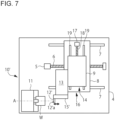
FIG. 7] FIG. 7 is a side view of main components of a turning system in another embodiment of the present invention. - [
FIG. 8A] FIG. 8A is a side view illustrating an arrangement of the cutting edge in the cutting position in the turning method. - [
FIG. 8B] FIG. 8B is a side view illustrating semi-finishing processing in the turning method. - [
FIG. 8C] FIG. 8C is a side view illustrating separation of the cutting edge from a surface of a workpiece in the turning method. - [
FIG. 8D] FIG. 8D is a side view illustrating retraction of the turning tool in the turning method. - [
FIG. 9A] FIG. 9A is a side view illustrating a dimension measurement in the turning method. - [
FIG. 9B] FIG. 9B is a side view illustrating finishing processing in the turning method. - [
FIG. 9C] FIG. 9C is a side view illustrating completion of the finishing processing in the turning method. - Hereinafter, a turning method, a machining system, and a machining program for a workpiece according to the present invention will be described in detail with reference to
FIGS. 1 to 6 . - First, a configuration of the machining system will be described with reference to
FIG. 1 . - As illustrated in
FIG. 1 , amachining system 1 includes aprocessing machine 10 and acontroller 2, which controls operations of theprocessing machine 10. Thecontroller 2 is capable of driving theprocessing machine 10 in accordance with a machining program 3, which has been stored beforehand, can causing theprocessing machine 10 to automatically perform turning on a workpiece W. In addition, arobot 20, which serves as a measuring apparatus for measuring a processed dimension of the workpiece W, is provided outside the processingmachine 10, and thecontroller 2 controls the driving of therobot 20 in a similar manner. Here, thecontroller 2 may be installed in a plurality of locations, and may include a control circuit connected with a communication unit. For example, some or all of control processes for driving therobot 20 may be conducted by a control circuit that is installed in another location different from the location where a control circuit for controlling the driving of theprocessing machine 10 is installed. - The processing
machine 10 includes: aspindle apparatus 11, which holds the workpiece W and which rotates the workpiece W about a rotation axis A; atool post 13, such as a turret, to which aturning tool 12 is fixed; afirst movement apparatus 14, which moves theturning tool 12 together with thetool post 13 in a radial direction of the rotation axis A to adjust the position of acutting edge 12a of theturning tool 12; and asecond movement apparatus 16, which moves theturning tool 12 together with thefirst movement apparatus 14 and thetool post 13 in parallel with the rotation axis A to adjust the position of thecutting edge 12a of theturning tool 12. In addition, athird movement apparatus 15, which is capable of moving theturning tool 12 relative to thetool post 13, is provided between thetool post 13 and theturning tool 12. It is to be noted that theturning tool 12 is disposed to extend substantially in parallel with the rotation axis A. - Here, the
second movement apparatus 16 includes acarriage 8, a linear guide 7, aball screw 6, and aservomotor 5. Thecarriage 8 is attached to the two rails of the linear guide 7, which are provided on abase 4 of theprocessing machine 10, and which extends in parallel with the rotation axis A. Thecarriage 8 is slidable along the linear guide 7, and is further screwed by theball screw 6, which extends in parallel with the rotation axis A. Theball screw 6 is connected with theservomotor 5. By driving theservomotor 5, theball screw 6 is rotated to enable thecarriage 8 to move in parallel with the rotation axis A. - Furthermore, the
first movement apparatus 14 includes: atool post base 9, which is connected with thetool post 13; alinear guide 19; aball screw 18; and aservomotor 17. Thetool post base 9 is attached to the two rails of thelinear guide 19, which are provided on thecarriage 8 of thesecond movement apparatus 16, and which extend in the radial direction of the rotation axis A. Thetool post base 9 is slidable along thelinear guide 19, and is further screwed by theball screw 18, which extends in parallel with thelinear guide 19. The ball screw 18 is connected with theservomotor 17. By driving theservomotor 17, theball screw 18 is rotated to enable thetool post base 9 of thefirst movement apparatus 14 to move relative to thecarriage 8 of thesecond movement apparatus 16 in the radial direction of the rotation axis A. - The
first movement apparatus 14 causes theturning tool 12 to be movable in the radial direction of the rotation axis A with respect to the workpiece W to be subject to turning, and a radial position of thecutting edge 12a is adjusted. In addition, thesecond movement apparatus 16 causes theturning tool 12 to be movable in a direction parallel to the rotation axis A with respect to the workpiece W to be subject to turning, and an axial position of thecutting edge 12a is adjusted. Thus, thecutting edge 12a of theturning tool 12 is adjusted to a cutting position, and it becomes possible to give a feed in turning. For thefirst movement apparatus 14 and thesecond movement apparatus 16, a sufficient amount of movement corresponding to the size of the workpiece W has to be ensured in a feed accompanied by such turning and retraction to be described later. Thefirst movement apparatus 14 and thesecond movement apparatus 16 each may have a movable range equal to or larger than 100 millimeters, for example. - Further, the
third movement apparatus 15 is capable of moving theturning tool 12 relative to thefirst movement apparatus 14 in the radial direction of the rotation axis A. Thethird movement apparatus 15 is preferably higher in positional accuracy than thefirst movement apparatus 14, and is smaller in movable range than thefirst movement apparatus 14. Thethird movement apparatus 15 has a movable range in which an error of a processed dimension caused by semi-finishing processing of the workpiece W based on the positional accuracy of thefirst movement apparatus 14 is correctable in finishing processing, and is capable of determining the position of thecutting edge 12a with high accuracy. It is to be noted that the movable range of thethird movement apparatus 15 may be equal to or smaller than one millimeter, for example. That is, the movable range of thethird movement apparatus 15 may be 1/100 or less the movable range of thefirst movement apparatus 14. Thus, the position of thecutting edge 12a, which has been adjusted by thefirst movement apparatus 14, is further finely adjustable in the radial direction of the rotation axis A. Examples of the method for driving thethird movement apparatus 15 may include elastic deformation of a tool holder by use of hydraulic pressure, the use of a linear motor, the use of a slider screwed with a ball screw rotated by a servomotor. - The
robot 20, which serves as a measuring apparatus, includes a measuringinstrument 22 at a tip end of arobot arm 21, inserts its tip end into the inside of theprocessing machine 10 from the outside of the machine in accordance with a drive command from thecontroller 2, and is thus capable of measuring the processed dimension of the workpiece W, which is held by thespindle apparatus 11. For example, an air gauge using an air micrometer of pneumatic type can be suitably used for the measuringinstrument 22. - Next, as an operation of the
machining system 1, a method for performing turning on an outer surface or an inner surface of the workpiece W will be described with reference toFIG. 2 together withFIGS. 3 and4 . It is to be noted that the workpiece W is held by thespindle apparatus 11, in a state in which rough processing has been completed on the workpiece W. - Referring to
FIG. 2 together withFIG. 3A , the workpiece W, which is held by thespindle apparatus 11, is rotated about the rotation axis A. Then, the first movement apparatus 14 (seeFIG. 1 ) is driven to locate thecutting edge 12a of theturning tool 12, which is attached to thetool post 13, at a cutting position for the semi-finishing processing of the workpiece W, and positioning is performed (S1). Here, the cutting position for the semi-finishing processing is specified by a radial position in which a finishing allowance is left with respect to a target dimension in the finishing processing in consideration of the positional accuracy of thefirst movement apparatus 14 in the radial direction, and an axial position for starting a feed in performing turning in the axial direction parallel to the rotation axis A. Such an axial position is adjusted by thesecond movement apparatus 16. - Then, as illustrated in
FIG. 3B , thesecond movement apparatus 16 is driven to move theturning tool 12, which is attached to thetool post 13, together with thefirst movement apparatus 14 in a first direction DR1 toward thespindle apparatus 11 along a movement axis A', which is parallel to the rotation axis A, and turning as the semi-finishing processing is performed on the workpiece W (S2). - Here, as illustrated in
FIG. 3C , after turning is performed to a predetermined position, thethird movement apparatus 15 is preferably driven to separate thecutting edge 12a from the surface of the workpiece W. - Next, as illustrated in
FIG. 3D , thesecond movement apparatus 16 is driven to move thetool post 13 in a second direction DR2, which is a reverse direction to the first direction DR1 along the movement axis A', which is parallel to the rotation axis A, and theturning tool 12 is retracted from the vicinity of the workpiece W (S3). In this situation, the driving of thefirst movement apparatus 14 is locked, and thefirst movement apparatus 14 does not move in the radial direction of thetool post 13. In the retraction in this manner, as described above, thethird movement apparatus 15 is driven to separate thecutting edge 12a from the surface of the workpiece W, so that an occurrence of a return mark can be prevented. It is to be noted that the occurrence of the return mark may not necessarily be prevented, and the driving of thethird movement apparatus 15 for separating thecutting edge 12a from the surface of the workpiece W may be omitted. - Next, as illustrated in
FIG. 4A , the processed dimension of the workpiece W is measured (S4). Here, the measurement is conducted by driving therobot 20, which serves as the measuring apparatus, to insert therobot arm 21 from the outside of theprocessing machine 10 and bring the measuringinstrument 22 into close proximity to the workpiece W. Since theturning tool 12 has been retracted as described above, the measuringinstrument 22 can be brought into close proximity to the workpiece W. It is to be noted that, instead of therobot 20, a measuring instrument provided in the machine may be used, or the measurement may be conducted manually by an operator. The processed dimension that has been measured is input, as a measurement result, into thecontroller 2. - The
controller 2 calculates a radial position of the cutting position for next finishing processing, based on the measurement result of the processed dimension of the workpiece W (S5). In detail, the radial position is determined to correct an error between a target value of a finished dimension and the processed dimension that has been measured. Then, thethird movement apparatus 15 is driven to adjust the position of theturning tool 12 so as to locate thecutting edge 12a at the radial position that has been determined. - Next, as illustrated in
FIG. 4B , as the finishing processing, thesecond movement apparatus 16 is driven to move theturning tool 12, which is attached to thetool post 13, again in the first direction DR1 along a movement axis A', which is parallel to the rotation axis A, and turning is performed on the workpiece W (S6). - Then, as illustrated in
FIG. 4C , turning is performed to a predetermined position, and the finishing processing ends. After the finishing processing ends, thethird movement apparatus 15 may be driven to separate thecutting edge 12a from the surface of the workpiece W. - Furthermore, the turning
tool 12 is retracted (S7), and the finished dimension is measured (S8). Here, in a case where the finished dimension falls within a dimensional tolerance, thefirst movement apparatus 14 and thesecond movement apparatus 16 are returned to the original positions, and the turning processing ends (S9; Yes). In this situation, a correction value for thethird movement apparatus 15 to correct an error in the finished dimension may be calculated to be used for next finishing processing. - In a case where the finished dimension does not fall within the dimensional tolerance, the remainder of the machining allowance is checked (S9; No). In a case where the finished dimension that has been measured is smaller than a predetermined one and no machining allowance remains (S10; Yes), an alarm is issued and then the processing ends. On the other hand, in a case where the finished dimension is larger than the predetermined one and the machining allowance remains (S10; No), the processing returns to the calculation of the cutting position in the finishing processing (S5), and performs the calculation again. It is to be noted that the driving of the processing machine10 and the driving of the
robot 20 are each based on a command from thecontroller 2 in accordance with the machining program 3. - By performing turning in the above-described method, the turning
tool 12 is not moved by thefirst movement apparatus 14, after the positioning in the semi-finishing processing (S1) until the finishing processing (S6). In other words, the position of thefirst movement apparatus 14 remains fixed at least until the finishing processing (S6). This makes the dimensional accuracy in the radial direction irrelevant to the positional accuracy of thefirst movement apparatus 14 in the finishing processing, and makes the dimensional accuracy in the radial direction dependent on the positional accuracy of thethird movement apparatus 15. As described above, thethird movement apparatus 15 is higher in positional accuracy than thefirst movement apparatus 14, and turning is enabled with such high positional accuracy. This also meets the demand for a narrow dimensional tolerance of, for example, 10 µm or less. That is, machine working for which the narrow dimensional tolerance is demanded is achievable by only turning, without depending on grinding. - It is to be noted that in a case of performing turning on a plurality of workpieces W successively, it is conceivable that the
first movement apparatus 14 is not made to move, the movement is limited to only the direction parallel to the rotation axis A by thesecond movement apparatus 16, and the finishing processing is performed by use of an identical correction value to omit the dimension measurement after the semi-finishing processing. However, a thermal displacement of theprocessing machine 10 caused by repeated machining and/or a plurality of times of repeated movements of thesecond movement apparatus 16 in the direction parallel to the rotation axis A can be assumed to degrade the dimensional accuracy in the radial direction. For this reason, the dimension measurement (S4) after the semi-finishing processing is preferably performed on each workpiece W every time. - In addition, the thermal displacement caused by successively performing turning on the plurality of workpieces W can also occur in the
third movement apparatus 15. On the other hand, as described above, thethird movement apparatus 15 has a smaller movable range. Hence, the thermal displacement that occurs in thethird movement apparatus 15 is much smaller than the thermal displacement in thefirst movement apparatus 14 or thesecond movement apparatus 16, each of which has a larger movable range. Therefore, even in the case where the thermal displacement occurs due to successive machining, the machine working for which a narrow dimensional tolerance is demanded is achievable, according to the above-described turning method. - In addition, as illustrated in
FIG. 5 , the turningtool 12 is also preferably arranged to extend substantially in parallel with the rotation axis A. Such an arrangement also enables turning to be performed, in the above-described method, on the inside of a circular recess C, which is centered around the rotation axis A in the workpiece W. That is, thecutting edge 12a of theturning tool 12 is inserted into the recess C to perform turning on the respective wall surfaces of an inner surface side and an outer surface side. Therefore, even though it is difficult to insert a grinding wheel into the recess or the like of the workpiece, or even though the grinding wheel is insertable but grinding requires time and labor, the machine working for which a narrow dimensional tolerance is demanded is achievable automatically and successively. - As illustrated in
FIG. 6 , in the case of performing turning on the workpiece W having a long size in the direction along the rotation axis A, it is desirable to arrange asteady rest 19, which supports the workpiece W, between thespindle apparatus 11 and the cutting position of theturning tool 12 for cutting the workpiece W, in a similar manner to other cases of turning. Such an arrangement also enables turning to be performed in a similar manner as described above. - It is to be noted that even in a case of performing only finishing processing without performing the semi-finishing processing, by applying the same method from the measurement of the processed dimension (S4) that has been described above, the machine working for which a narrow dimensional tolerance is demanded is achievable by only turning. In addition, the turning method that has been described above is usable for performing turning on the inner surface and the outer surface of the workpiece. The processing
machine 10 may be another type of processing machine, such as the turret lathe or the combined processing machine described above. - Next, a turning method for performing turning on an end surface that is a surface orthogonal to the rotation axis A in the workpiece will be described. First, a configuration of the processing machine will be described.
- As illustrated in
FIG. 7 , a processing machine 10' is common to theprocessing machine 10, which has been described above, except some components. What is mainly different is that a fourth movement apparatus 15', which moves a turning tool 12' in parallel with the rotation axis A, is provided instead of thethird movement apparatus 15, which moves theturning tool 12 in the radial direction of the rotation axis A. Specifically, in contrast to theprocessing machine 10, in the processing machine 10', with regard to thetool post 13, the entire movement apparatus including the turning tool is exchanged. In a case where a turret is used as thetool post 13, such a turret is rotated to complete this exchange. The other components such as thefirst movement apparatus 14 and thesecond movement apparatus 16 are similar to those of theprocessing machine 10. - The fourth movement apparatus 15' is also higher in positional accuracy than the
second movement apparatus 16, as in the case of thethird movement apparatus 15. Therefore, the fourth movement apparatus 15' preferably has a movable range smaller than that of thesecond movement apparatus 16. The fourth movement apparatus 15' has a movable range in which an error of the processed dimension caused by the semi-finishing processing on the workpiece W based on the positional accuracy of thesecond movement apparatus 16 is correctable in the finishing processing, and the position of a cutting edge 12'a can be determined with high accuracy. It is to be noted that the movable range of the fourth movement apparatus 15' may be equal to or smaller than one millimeter, for example. That is, the movable range of the fourth movement apparatus 15' may be 1/100 or less the movable range of thesecond movement apparatus 16. - Other details of the fourth movement apparatus 15' are similar to those of the
third movement apparatus 15, and thus the descriptions will be omitted. - Next, a turning method for performing turning on an end surface of the workpiece W by use of the processing machine 10' will be described.
- Referring to
FIG. 2 together withFIG. 8A , the workpiece W, which is held by thespindle apparatus 11, is rotated about the rotation axis A. Then, the second movement apparatus 16 (seeFIG. 7 ) is driven to locate the cutting edge 12'a of the turning tool 12', which is attached to thetool post 13, at a cutting position for the semi-finishing processing of the workpiece W, and positioning is performed (S1). Here, the cutting position for the semi-finishing processing is specified by an axial position in which a finishing allowance is left with respect to a target dimension in the finishing processing in consideration of the positional accuracy of thesecond movement apparatus 16 in the axial direction parallel to the rotation axis A, and a radial position for starting a feed in performing turning in the radial direction of the rotation axis A. Such a radial position is adjusted by thefirst movement apparatus 14. - Then, as illustrated in
FIG. 8B , thefirst movement apparatus 14 is driven to move the turning tool 12', which is attached to thetool post 13, in a third direction DR3 toward the rotation center of the rotation axis A in the workpiece W and along a movement axis R in the radial direction of the rotation axis A, and turning as the semi-finishing processing is performed on an end surface of the workpiece W (S2). - Here, as illustrated in
FIG. 8C , after turning is performed to a predetermined position, the fourth movement apparatus 15' is preferably driven to separate the cutting edge 12'a from the surface of the workpiece W. - Next, as illustrated in
FIG. 8D , thefirst movement apparatus 14 is driven to move the turning tool 12', which is attached to thetool post 13, in a fourth direction DR4, which is a reverse direction to the third direction DR3, along the movement axis R in the radial direction of the rotation axis A, and the turning tool 12' is retracted from the vicinity of the workpiece W (S3). In this situation, the driving of thesecond movement apparatus 16 is locked, and thesecond movement apparatus 16 does not move in a direction parallel to the rotation axis A of thetool post 13. In the retraction in this manner, the fourth movement apparatus 15' as described above is driven to separate the cutting edge 12'a from the surface of the workpiece W, so that an occurrence of a return mark can be prevented. It is to be noted that the occurrence of the return mark may not necessarily be prevented, and the driving of the fourth movement apparatus 15' for separating the cutting edge 12'a from the surface of the workpiece W may be omitted. - Next, as illustrated in
FIG. 9A , the processed dimension of the workpiece W is measured (S4). For example, the distance between end surfaces is measured by a measuring instrument 22' having a caliper-like shape, so that the distance can be set as a processed dimension. The processed dimension that has been measured is input, as a measurement result, into thecontroller 2. - The
controller 2 calculates an axial position of the cutting position for next finishing processing, based on the measurement result of the processed dimension of the workpiece W (S5). In detail, the axial position is determined to correct an error between a target value of the finished dimension and the dimension that has been measured. Then, the fourth movement apparatus 15' is driven to adjust the position of the turning tool 12' so as to locate the cutting edge 12'a at the axial position that has been determined. - Next, as illustrated in
FIG. 9B , as the finishing processing, thefirst movement apparatus 14 is driven to move the turning tool 12', which is attached to thetool post 13, again in the third direction DR3 along the movement axis R in the radial direction of the rotation axis A, and turning is performed on the workpiece W (S6). - Then, as illustrated in
FIG. 9C , turning is performed to a predetermined position, and the finishing processing ends. Other details of the turning method are similar to those of the turning method by the above-describedprocessing machine 10, and thus the descriptions will be omitted. - By performing turning in the above-described method, the turning tool 12' is not moved by the
second movement apparatus 16, after the positioning in the semi-finishing processing (S1) until the finishing processing (S6). In other words, the driving of thesecond movement apparatus 16 remains locked at least until the finishing processing (S6). This makes the dimensional accuracy in a direction parallel to the rotation axis A irrelevant to the positional accuracy of thesecond movement apparatus 16 in the finishing processing, and makes the dimensional accuracy dependent on the positional accuracy of the fourth movement apparatus 15'. As described above, the fourth movement apparatus 15' is higher in positional accuracy than thesecond movement apparatus 16, and turning is enabled with such high positional accuracy. This also meets the demand for a narrow dimensional tolerance of, for example, 10 µm or less. That is, machine working for which the narrow dimensional tolerance is demanded is achievable by only turning, without depending on grinding. - While exemplary embodiments according to the present invention and accompanying variations thereof have been described above, the present invention is not necessarily limited thereto, and may be varied by those skilled in the art, as appropriate. That is, various alternative embodiments and modifications can be found by those skilled in the art without departing from the scope of the appended claims.
- 1 ... Machining system, 2 ... Controller, 3 ... Machining program, 10 ... Processing machine, 11 ... Spindle apparatus, 12 ... Turning tool, 12a ... Cutting edge, 13 ... Tool post, 14 ... First movement apparatus, 15 ... Third movement apparatus, 15' ... Fourth movement apparatus, 16 ... Second movement apparatus, 20 ... Robot (measuring apparatus), A ... Rotation axis, A' ... Movement axis, W ... Workpiece
Claims (15)
- A turning method for a workpiece rotatable about a rotation axis, the turning method comprising:driving a first movement apparatus for moving a turning tool in a radial direction of the rotation axis to locate a cutting edge of the turning tool at a first radial position in the radial direction;driving a second movement apparatus for moving the turning tool in parallel with the rotation axis, performing turning on the workpiece, and then moving the turning tool in a reverse direction to retract the turning tool from the workpiece;measuring a processed dimension of the workpiece, and calculating an error between the processed dimension that has been measured and a target dimension;driving a third movement apparatus for moving the turning tool relative to the first movement apparatus in the radial direction of the rotation axis to locate the cutting edge of the turning tool at a second radial position so as to correct the error; anddriving the second movement apparatus to move the turning tool in parallel with the rotation axis, and performing turning on the workpiece.
- The turning method according to claim 1, wherein the cutting edge of the turning tool is located at the first radial position to lock driving of the first movement apparatus.
- The turning method according to claim 1 or 2, wherein the third movement apparatus moves the turning tool relative to the first movement apparatus by an amount corresponding to the error.
- The turning method according to any one of claims 1 to 3, wherein the third movement apparatus moves the turning tool relative to the first movement apparatus within one millimeter.
- The turning method according to any one of claims 1 to 4, wherein the turning is performed on an inside of a recess of the workpiece.
- A turning method for a workpiece rotatable about a rotation axis, the turning method comprising:driving a second movement apparatus for moving a turning tool in parallel with the rotation axis to locate a cutting edge of the turning tool at a first axial position in a direction parallel to the rotation axis;driving a first movement apparatus for moving the turning tool in a radial direction of the rotation axis, performing turning on the workpiece, and then moving the turning tool in a reverse direction to retract the turning tool from the workpiece;measuring a processed dimension of the workpiece, and calculating an error between the processed dimension that has been measured and a target dimension;driving a fourth movement apparatus for moving the turning tool relative to the second movement apparatus in parallel with the rotation axis to locate the cutting edge of the turning tool at a second axial position so as to correct the error; anddriving the first movement apparatus to move the turning tool in the radial direction, and performing turning on the workpiece.
- The turning method according to claim 6, wherein the cutting edge of the turning tool is located at the first axial position to lock driving of the second movement apparatus.
- The turning method according to claim 6 or 7, wherein the fourth movement apparatus moves the turning tool relative to the second movement apparatus by an amount corresponding to the error.
- The turning method according to any one of claims 6 to 8, wherein the fourth movement apparatus moves the turning tool relative to the second movement apparatus within one millimeter.
- A machining system for a workpiece, the machining system comprising:a machining apparatus configured to perform turning on the workpiece;a measuring apparatus configured to measure a processed dimension of the workpiece; anda controller configured to control driving of the machining apparatus and the measuring apparatus,wherein the machining apparatus comprises:a spindle apparatus configured to rotate the workpiece about a rotation axis;a first movement apparatus configured to move a turning tool in a radial direction of the rotation axis;a second movement apparatus configured to move the turning tool in parallel with the rotation axis; anda third movement apparatus having a movable range smaller than a movable range of the first movement apparatus in the radial direction of the rotation axis, and configured to move the turning tool relative to the first movement apparatus in the radial direction of the rotation axis, andwherein the controller is configured to control the driving of the machining apparatus and the measuring apparatus to perform the method of one of claims 1 to 5.
- The machining system according to claim 10, wherein the movable range of the third movement apparatus is at most 1/100 the movable range of the first movement apparatus.
- A machining system for a workpiece, the machining system comprising:a machining apparatus configured to perform turning on the workpiece;a measuring apparatus configured to measure a processed dimension of the workpiece; anda controller configured to control driving of the machining apparatus and the measuring apparatus,wherein the machining apparatus comprises:a spindle apparatus configured to rotate the workpiece about a rotation axis;a first movement apparatus configured to move a turning tool in a radial direction of the rotation axis;a second movement apparatus configured to move the turning tool in parallel with the rotation axis; anda fourth movement apparatus having a movable range smaller than a movable range of the second movement apparatus in a direction parallel to the rotation axis, and configured to move the turning tool relative to the second movement apparatus in parallel with the rotation axis, andwherein the controller is configured to control the driving of the machining apparatus and the measuring apparatus to perform the method of one of claims 6 to 9.
- The machining system according to claim 12, wherein the movable range of the fourth movement apparatus is at most 1/100 the movable range of the second movement apparatus.
- A machining program comprising an instruction for causing a machining apparatus to perform the method of one of claims 1 to 5, the machining apparatus comprising:a first movement apparatus configured to move a turning tool in a radial direction of a rotation axis of a workpiece;a second movement apparatus configured to move the turning tool in parallel with the rotation axis; anda third movement apparatus configured to move the turning tool relative to the first movement apparatus in a radial direction of the rotation axis.
- A machining program comprising an instruction for causing a machining apparatus to perform the method of one of claims 6 to 9, the machining apparatus comprising:a first movement apparatus configured to move a turning tool in a radial direction of a rotation axis of a workpiece;a second movement apparatus configured to move the turning tool in parallel with the rotation axis; anda fourth movement apparatus configured to move the turning tool relative to the second movement apparatus in parallel with the rotation axis.
Applications Claiming Priority (1)
| Application Number | Priority Date | Filing Date | Title |
|---|---|---|---|
| PCT/JP2021/002450 WO2022157976A1 (en) | 2021-01-25 | 2021-01-25 | Turning method, machining system, and machining program |
Publications (3)
| Publication Number | Publication Date |
|---|---|
| EP4219048A1 true EP4219048A1 (en) | 2023-08-02 |
| EP4219048A4 EP4219048A4 (en) | 2023-12-06 |
| EP4219048B1 EP4219048B1 (en) | 2024-10-16 |
Family
ID=80500322
Family Applications (1)
| Application Number | Title | Priority Date | Filing Date |
|---|---|---|---|
| EP21921084.6A Active EP4219048B1 (en) | 2021-01-25 | 2021-01-25 | Turning method, machining system, and machining program |
Country Status (5)
| Country | Link |
|---|---|
| US (1) | US12583070B2 (en) |
| EP (1) | EP4219048B1 (en) |
| JP (1) | JP7002702B1 (en) |
| CN (1) | CN116710222A (en) |
| WO (1) | WO2022157976A1 (en) |
Family Cites Families (13)
| Publication number | Priority date | Publication date | Assignee | Title |
|---|---|---|---|---|
| JPS5345034B2 (en) * | 1974-06-05 | 1978-12-04 | ||
| JPS5155080A (en) * | 1974-11-11 | 1976-05-14 | Toyota Motor Co Ltd | KOGUHASAKI ICHIHOSEIHOHO OYOBISONO SOCHI |
| JPS58137542A (en) | 1982-02-10 | 1983-08-16 | Nakamuratome Seimitsu Kogyo Kk | Supporting structure for tool rest of combined lathe |
| US4974165A (en) * | 1988-11-28 | 1990-11-27 | Mechanical Technology Incorporated | Real time machining control system including in-process part measuring and inspection |
| US5917726A (en) * | 1993-11-18 | 1999-06-29 | Sensor Adaptive Machines, Inc. | Intelligent machining and manufacturing |
| JP2002052445A (en) * | 2000-08-08 | 2002-02-19 | Mitsubishi Heavy Ind Ltd | Cutting device and method |
| JP2002066848A (en) * | 2000-08-28 | 2002-03-05 | Matsushita Electric Ind Co Ltd | Processing equipment for hydrodynamic bearings |
| JP2002307202A (en) * | 2001-04-18 | 2002-10-23 | Seibu Electric & Mach Co Ltd | A processing device that processes both plate-like end faces of a workpiece |
| JP4831386B2 (en) * | 2001-04-26 | 2011-12-07 | エヌティーエンジニアリング株式会社 | Wearing state inspection device for tool holders for work machines |
| JP5896844B2 (en) * | 2012-07-02 | 2016-03-30 | 国立大学法人名古屋大学 | Machine tool with workpiece diameter measurement function |
| JP6576758B2 (en) * | 2015-09-18 | 2019-09-18 | シチズン時計株式会社 | Cutting apparatus and control method thereof |
| JP6837020B2 (en) * | 2018-02-19 | 2021-03-03 | 東芝三菱電機産業システム株式会社 | Cutting equipment and cutting method |
| JP7423030B2 (en) * | 2019-03-08 | 2024-01-29 | 中村留精密工業株式会社 | Machine tool with automatic correction function when changing tools |
-
2021
- 2021-01-25 EP EP21921084.6A patent/EP4219048B1/en active Active
- 2021-01-25 CN CN202180091263.6A patent/CN116710222A/en active Pending
- 2021-01-25 JP JP2021534192A patent/JP7002702B1/en active Active
- 2021-01-25 WO PCT/JP2021/002450 patent/WO2022157976A1/en not_active Ceased
-
2023
- 2023-05-18 US US18/319,484 patent/US12583070B2/en active Active
Also Published As
| Publication number | Publication date |
|---|---|
| JPWO2022157976A1 (en) | 2022-07-28 |
| EP4219048B1 (en) | 2024-10-16 |
| CN116710222A (en) | 2023-09-05 |
| WO2022157976A1 (en) | 2022-07-28 |
| US20230302595A1 (en) | 2023-09-28 |
| US12583070B2 (en) | 2026-03-24 |
| EP4219048A4 (en) | 2023-12-06 |
| JP7002702B1 (en) | 2022-01-20 |
Similar Documents
| Publication | Publication Date | Title |
|---|---|---|
| CN109465502B (en) | Method and apparatus for shaving teeth | |
| EP2846206B1 (en) | Device and method for automatically setting tool offset value of machine tool | |
| CN102666007B (en) | machine tool | |
| CN109531274B (en) | Z-direction reference plane detection and setting method of vertical milling machine | |
| KR100976899B1 (en) | Machining error correction method in numerical control machine tool and grinding machine using it | |
| JP2008119784A (en) | Attitude assurance system of 5-axis machine for inclined machining | |
| CN103365246A (en) | Device for error correction for CNC machines | |
| WO2013073317A1 (en) | Machine tool | |
| JP2011206862A (en) | Method of positioning rotary tool in multishaft processing machine | |
| US4417490A (en) | Lathe tool calibrator and method | |
| KR20130009433A (en) | Method and device for compensating position to change tools of a machine tool | |
| JP6168396B2 (en) | Machine Tools | |
| EP4219048B1 (en) | Turning method, machining system, and machining program | |
| JP5846400B2 (en) | Machine tool and its thermal deformation correction method | |
| JP2018027599A (en) | Method for correcting machining error of machine tool | |
| US11376667B2 (en) | Machining tool and workpiece measurement method | |
| JP2007257606A (en) | Tool positioning error compensation method | |
| TW201913251A (en) | Work piece processing method and processing system thereof | |
| JP6623061B2 (en) | Machine tool and control method of machine tool | |
| EP4163743A1 (en) | Batch production system and batch production method | |
| JP4545501B2 (en) | Tool centering method and tool measuring method | |
| JP2012110983A (en) | Instruction method of stopping main shaft at fixed stopping position and workpiece measuring method | |
| JP7456191B2 (en) | Gear processing equipment and gear processing method | |
| JP2019104082A (en) | Nc grinding device and method of grinding workpiece | |
| US7103441B2 (en) | Calibration procedures and such using an erosion and grinding machine |
Legal Events
| Date | Code | Title | Description |
|---|---|---|---|
| STAA | Information on the status of an ep patent application or granted ep patent |
Free format text: STATUS: THE INTERNATIONAL PUBLICATION HAS BEEN MADE |
|
| PUAI | Public reference made under article 153(3) epc to a published international application that has entered the european phase |
Free format text: ORIGINAL CODE: 0009012 |
|
| STAA | Information on the status of an ep patent application or granted ep patent |
Free format text: STATUS: REQUEST FOR EXAMINATION WAS MADE |
|
| 17P | Request for examination filed |
Effective date: 20230428 |
|
| AK | Designated contracting states |
Kind code of ref document: A1 Designated state(s): AL AT BE BG CH CY CZ DE DK EE ES FI FR GB GR HR HU IE IS IT LI LT LU LV MC MK MT NL NO PL PT RO RS SE SI SK SM TR |
|
| STAA | Information on the status of an ep patent application or granted ep patent |
Free format text: STATUS: EXAMINATION IS IN PROGRESS |
|
| A4 | Supplementary search report drawn up and despatched |
Effective date: 20231107 |
|
| RIC1 | Information provided on ipc code assigned before grant |
Ipc: G05B 19/18 20060101ALI20231101BHEP Ipc: B23B 7/12 20060101ALI20231101BHEP Ipc: B23Q 17/20 20060101ALI20231101BHEP Ipc: B23B 25/06 20060101ALI20231101BHEP Ipc: B23B 5/12 20060101ALI20231101BHEP Ipc: B23B 5/00 20060101ALI20231101BHEP Ipc: B23B 1/00 20060101AFI20231101BHEP |
|
| 17Q | First examination report despatched |
Effective date: 20231121 |
|
| DAV | Request for validation of the european patent (deleted) | ||
| DAX | Request for extension of the european patent (deleted) | ||
| REG | Reference to a national code |
Ref country code: DE Ref legal event code: R079 Free format text: PREVIOUS MAIN CLASS: B23B0001000000 Ref country code: DE Ref legal event code: R079 Ref document number: 602021020502 Country of ref document: DE Free format text: PREVIOUS MAIN CLASS: B23B0001000000 Ipc: G05B0019404000 |
|
| GRAP | Despatch of communication of intention to grant a patent |
Free format text: ORIGINAL CODE: EPIDOSNIGR1 |
|
| STAA | Information on the status of an ep patent application or granted ep patent |
Free format text: STATUS: GRANT OF PATENT IS INTENDED |
|
| RIC1 | Information provided on ipc code assigned before grant |
Ipc: B23B 7/12 20060101ALI20240517BHEP Ipc: B23Q 17/20 20060101ALI20240517BHEP Ipc: B23B 25/06 20060101ALI20240517BHEP Ipc: B23B 5/12 20060101ALI20240517BHEP Ipc: B23B 5/00 20060101ALI20240517BHEP Ipc: B23B 1/00 20060101ALI20240517BHEP Ipc: G05B 19/404 20060101AFI20240517BHEP |
|
| INTG | Intention to grant announced |
Effective date: 20240626 |
|
| GRAS | Grant fee paid |
Free format text: ORIGINAL CODE: EPIDOSNIGR3 |
|
| GRAA | (expected) grant |
Free format text: ORIGINAL CODE: 0009210 |
|
| STAA | Information on the status of an ep patent application or granted ep patent |
Free format text: STATUS: THE PATENT HAS BEEN GRANTED |
|
| AK | Designated contracting states |
Kind code of ref document: B1 Designated state(s): AL AT BE BG CH CY CZ DE DK EE ES FI FR GB GR HR HU IE IS IT LI LT LU LV MC MK MT NL NO PL PT RO RS SE SI SK SM TR |
|
| REG | Reference to a national code |
Ref country code: GB Ref legal event code: FG4D |
|
| REG | Reference to a national code |
Ref country code: DE Ref legal event code: R096 Ref document number: 602021020502 Country of ref document: DE Ref country code: CH Ref legal event code: EP |
|
| REG | Reference to a national code |
Ref country code: IE Ref legal event code: FG4D |
|
| REG | Reference to a national code |
Ref country code: LT Ref legal event code: MG9D |
|
| REG | Reference to a national code |
Ref country code: AT Ref legal event code: MK05 Ref document number: 1733422 Country of ref document: AT Kind code of ref document: T Effective date: 20241016 |
|
| PG25 | Lapsed in a contracting state [announced via postgrant information from national office to epo] |
Ref country code: NL Free format text: LAPSE BECAUSE OF FAILURE TO SUBMIT A TRANSLATION OF THE DESCRIPTION OR TO PAY THE FEE WITHIN THE PRESCRIBED TIME-LIMIT Effective date: 20241016 |
|
| PG25 | Lapsed in a contracting state [announced via postgrant information from national office to epo] |
Ref country code: NL Free format text: LAPSE BECAUSE OF FAILURE TO SUBMIT A TRANSLATION OF THE DESCRIPTION OR TO PAY THE FEE WITHIN THE PRESCRIBED TIME-LIMIT Effective date: 20241016 |
|
| PG25 | Lapsed in a contracting state [announced via postgrant information from national office to epo] |
Ref country code: IS Free format text: LAPSE BECAUSE OF FAILURE TO SUBMIT A TRANSLATION OF THE DESCRIPTION OR TO PAY THE FEE WITHIN THE PRESCRIBED TIME-LIMIT Effective date: 20250216 Ref country code: PT Free format text: LAPSE BECAUSE OF FAILURE TO SUBMIT A TRANSLATION OF THE DESCRIPTION OR TO PAY THE FEE WITHIN THE PRESCRIBED TIME-LIMIT Effective date: 20250217 Ref country code: HR Free format text: LAPSE BECAUSE OF FAILURE TO SUBMIT A TRANSLATION OF THE DESCRIPTION OR TO PAY THE FEE WITHIN THE PRESCRIBED TIME-LIMIT Effective date: 20241016 |
|
| PG25 | Lapsed in a contracting state [announced via postgrant information from national office to epo] |
Ref country code: FI Free format text: LAPSE BECAUSE OF FAILURE TO SUBMIT A TRANSLATION OF THE DESCRIPTION OR TO PAY THE FEE WITHIN THE PRESCRIBED TIME-LIMIT Effective date: 20241016 |
|
| PG25 | Lapsed in a contracting state [announced via postgrant information from national office to epo] |
Ref country code: BG Free format text: LAPSE BECAUSE OF FAILURE TO SUBMIT A TRANSLATION OF THE DESCRIPTION OR TO PAY THE FEE WITHIN THE PRESCRIBED TIME-LIMIT Effective date: 20241016 |
|
| PG25 | Lapsed in a contracting state [announced via postgrant information from national office to epo] |
Ref country code: ES Free format text: LAPSE BECAUSE OF FAILURE TO SUBMIT A TRANSLATION OF THE DESCRIPTION OR TO PAY THE FEE WITHIN THE PRESCRIBED TIME-LIMIT Effective date: 20241016 |
|
| PG25 | Lapsed in a contracting state [announced via postgrant information from national office to epo] |
Ref country code: NO Free format text: LAPSE BECAUSE OF FAILURE TO SUBMIT A TRANSLATION OF THE DESCRIPTION OR TO PAY THE FEE WITHIN THE PRESCRIBED TIME-LIMIT Effective date: 20250116 |
|
| PG25 | Lapsed in a contracting state [announced via postgrant information from national office to epo] |
Ref country code: LV Free format text: LAPSE BECAUSE OF FAILURE TO SUBMIT A TRANSLATION OF THE DESCRIPTION OR TO PAY THE FEE WITHIN THE PRESCRIBED TIME-LIMIT Effective date: 20241016 Ref country code: AT Free format text: LAPSE BECAUSE OF FAILURE TO SUBMIT A TRANSLATION OF THE DESCRIPTION OR TO PAY THE FEE WITHIN THE PRESCRIBED TIME-LIMIT Effective date: 20241016 Ref country code: GR Free format text: LAPSE BECAUSE OF FAILURE TO SUBMIT A TRANSLATION OF THE DESCRIPTION OR TO PAY THE FEE WITHIN THE PRESCRIBED TIME-LIMIT Effective date: 20250117 |
|
| PG25 | Lapsed in a contracting state [announced via postgrant information from national office to epo] |
Ref country code: PL Free format text: LAPSE BECAUSE OF FAILURE TO SUBMIT A TRANSLATION OF THE DESCRIPTION OR TO PAY THE FEE WITHIN THE PRESCRIBED TIME-LIMIT Effective date: 20241016 |
|
| PG25 | Lapsed in a contracting state [announced via postgrant information from national office to epo] |
Ref country code: RS Free format text: LAPSE BECAUSE OF FAILURE TO SUBMIT A TRANSLATION OF THE DESCRIPTION OR TO PAY THE FEE WITHIN THE PRESCRIBED TIME-LIMIT Effective date: 20250116 |
|
| PG25 | Lapsed in a contracting state [announced via postgrant information from national office to epo] |
Ref country code: SM Free format text: LAPSE BECAUSE OF FAILURE TO SUBMIT A TRANSLATION OF THE DESCRIPTION OR TO PAY THE FEE WITHIN THE PRESCRIBED TIME-LIMIT Effective date: 20241016 |
|
| PG25 | Lapsed in a contracting state [announced via postgrant information from national office to epo] |
Ref country code: DK Free format text: LAPSE BECAUSE OF FAILURE TO SUBMIT A TRANSLATION OF THE DESCRIPTION OR TO PAY THE FEE WITHIN THE PRESCRIBED TIME-LIMIT Effective date: 20241016 |
|
| REG | Reference to a national code |
Ref country code: DE Ref legal event code: R097 Ref document number: 602021020502 Country of ref document: DE |
|
| PG25 | Lapsed in a contracting state [announced via postgrant information from national office to epo] |
Ref country code: EE Free format text: LAPSE BECAUSE OF FAILURE TO SUBMIT A TRANSLATION OF THE DESCRIPTION OR TO PAY THE FEE WITHIN THE PRESCRIBED TIME-LIMIT Effective date: 20241016 |
|
| PG25 | Lapsed in a contracting state [announced via postgrant information from national office to epo] |
Ref country code: RO Free format text: LAPSE BECAUSE OF FAILURE TO SUBMIT A TRANSLATION OF THE DESCRIPTION OR TO PAY THE FEE WITHIN THE PRESCRIBED TIME-LIMIT Effective date: 20241016 |
|
| PG25 | Lapsed in a contracting state [announced via postgrant information from national office to epo] |
Ref country code: SK Free format text: LAPSE BECAUSE OF FAILURE TO SUBMIT A TRANSLATION OF THE DESCRIPTION OR TO PAY THE FEE WITHIN THE PRESCRIBED TIME-LIMIT Effective date: 20241016 |
|
| PG25 | Lapsed in a contracting state [announced via postgrant information from national office to epo] |
Ref country code: CZ Free format text: LAPSE BECAUSE OF FAILURE TO SUBMIT A TRANSLATION OF THE DESCRIPTION OR TO PAY THE FEE WITHIN THE PRESCRIBED TIME-LIMIT Effective date: 20241016 |
|
| PLBE | No opposition filed within time limit |
Free format text: ORIGINAL CODE: 0009261 |
|
| STAA | Information on the status of an ep patent application or granted ep patent |
Free format text: STATUS: NO OPPOSITION FILED WITHIN TIME LIMIT |
|
| REG | Reference to a national code |
Ref country code: CH Ref legal event code: PL |
|
| PG25 | Lapsed in a contracting state [announced via postgrant information from national office to epo] |
Ref country code: SE Free format text: LAPSE BECAUSE OF FAILURE TO SUBMIT A TRANSLATION OF THE DESCRIPTION OR TO PAY THE FEE WITHIN THE PRESCRIBED TIME-LIMIT Effective date: 20241016 |
|
| PG25 | Lapsed in a contracting state [announced via postgrant information from national office to epo] |
Ref country code: LU Free format text: LAPSE BECAUSE OF NON-PAYMENT OF DUE FEES Effective date: 20250125 Ref country code: MC Free format text: LAPSE BECAUSE OF FAILURE TO SUBMIT A TRANSLATION OF THE DESCRIPTION OR TO PAY THE FEE WITHIN THE PRESCRIBED TIME-LIMIT Effective date: 20241016 |
|
| 26N | No opposition filed |
Effective date: 20250717 |
|
| PG25 | Lapsed in a contracting state [announced via postgrant information from national office to epo] |
Ref country code: BE Free format text: LAPSE BECAUSE OF NON-PAYMENT OF DUE FEES Effective date: 20250131 |
|
| PG25 | Lapsed in a contracting state [announced via postgrant information from national office to epo] |
Ref country code: CH Free format text: LAPSE BECAUSE OF NON-PAYMENT OF DUE FEES Effective date: 20250131 |
|
| REG | Reference to a national code |
Ref country code: BE Ref legal event code: MM Effective date: 20250131 |
|
| PGFP | Annual fee paid to national office [announced via postgrant information from national office to epo] |
Ref country code: GB Payment date: 20251204 Year of fee payment: 6 |
|
| PGFP | Annual fee paid to national office [announced via postgrant information from national office to epo] |
Ref country code: FR Payment date: 20251128 Year of fee payment: 6 |
|
| PG25 | Lapsed in a contracting state [announced via postgrant information from national office to epo] |
Ref country code: IE Free format text: LAPSE BECAUSE OF NON-PAYMENT OF DUE FEES Effective date: 20250125 |
|
| PGFP | Annual fee paid to national office [announced via postgrant information from national office to epo] |
Ref country code: DE Payment date: 20251203 Year of fee payment: 6 |
|
| PGFP | Annual fee paid to national office [announced via postgrant information from national office to epo] |
Ref country code: IT Payment date: 20251219 Year of fee payment: 6 |