EP4219039A1 - Method and device for press-forming vehicular outer plate panel - Google Patents
Method and device for press-forming vehicular outer plate panel Download PDFInfo
- Publication number
- EP4219039A1 EP4219039A1 EP21885596.3A EP21885596A EP4219039A1 EP 4219039 A1 EP4219039 A1 EP 4219039A1 EP 21885596 A EP21885596 A EP 21885596A EP 4219039 A1 EP4219039 A1 EP 4219039A1
- Authority
- EP
- European Patent Office
- Prior art keywords
- punch
- elastic body
- die
- metal sheet
- character
- Prior art date
- Legal status (The legal status is an assumption and is not a legal conclusion. Google has not performed a legal analysis and makes no representation as to the accuracy of the status listed.)
- Pending
Links
Images




Classifications
-
- B—PERFORMING OPERATIONS; TRANSPORTING
- B21—MECHANICAL METAL-WORKING WITHOUT ESSENTIALLY REMOVING MATERIAL; PUNCHING METAL
- B21D—WORKING OR PROCESSING OF SHEET METAL OR METAL TUBES, RODS OR PROFILES WITHOUT ESSENTIALLY REMOVING MATERIAL; PUNCHING METAL
- B21D53/00—Making other particular articles
- B21D53/88—Making other particular articles other parts for vehicles, e.g. cowlings, mudguards
-
- B—PERFORMING OPERATIONS; TRANSPORTING
- B21—MECHANICAL METAL-WORKING WITHOUT ESSENTIALLY REMOVING MATERIAL; PUNCHING METAL
- B21D—WORKING OR PROCESSING OF SHEET METAL OR METAL TUBES, RODS OR PROFILES WITHOUT ESSENTIALLY REMOVING MATERIAL; PUNCHING METAL
- B21D22/00—Shaping without cutting, by stamping, spinning, or deep-drawing
- B21D22/10—Stamping using yieldable or resilient pads
-
- B—PERFORMING OPERATIONS; TRANSPORTING
- B21—MECHANICAL METAL-WORKING WITHOUT ESSENTIALLY REMOVING MATERIAL; PUNCHING METAL
- B21D—WORKING OR PROCESSING OF SHEET METAL OR METAL TUBES, RODS OR PROFILES WITHOUT ESSENTIALLY REMOVING MATERIAL; PUNCHING METAL
- B21D22/00—Shaping without cutting, by stamping, spinning, or deep-drawing
- B21D22/20—Deep-drawing
- B21D22/26—Deep-drawing for making peculiarly, e.g. irregularly, shaped articles
-
- B—PERFORMING OPERATIONS; TRANSPORTING
- B21—MECHANICAL METAL-WORKING WITHOUT ESSENTIALLY REMOVING MATERIAL; PUNCHING METAL
- B21D—WORKING OR PROCESSING OF SHEET METAL OR METAL TUBES, RODS OR PROFILES WITHOUT ESSENTIALLY REMOVING MATERIAL; PUNCHING METAL
- B21D24/00—Special deep-drawing arrangements in, or in connection with, presses
-
- B—PERFORMING OPERATIONS; TRANSPORTING
- B21—MECHANICAL METAL-WORKING WITHOUT ESSENTIALLY REMOVING MATERIAL; PUNCHING METAL
- B21D—WORKING OR PROCESSING OF SHEET METAL OR METAL TUBES, RODS OR PROFILES WITHOUT ESSENTIALLY REMOVING MATERIAL; PUNCHING METAL
- B21D24/00—Special deep-drawing arrangements in, or in connection with, presses
- B21D24/04—Blank holders; Mounting means therefor
-
- B—PERFORMING OPERATIONS; TRANSPORTING
- B21—MECHANICAL METAL-WORKING WITHOUT ESSENTIALLY REMOVING MATERIAL; PUNCHING METAL
- B21D—WORKING OR PROCESSING OF SHEET METAL OR METAL TUBES, RODS OR PROFILES WITHOUT ESSENTIALLY REMOVING MATERIAL; PUNCHING METAL
- B21D37/00—Tools as parts of machines covered by this subclass
- B21D37/10—Die sets; Pillar guides
Definitions
- the present invention relates to press forming methods and press forming apparatuses for outer panels of automobiles, the press forming methods and press forming apparatuses being for press forming metal sheets into outer panels of automobiles, the outer panels having character-lines formed therein.
- a metal sheet refers to a sheet formed of any of various metals, such as stainless steel, aluminum, and magnesium, for example, a hot-rolled steel sheet, a cold - rolled steel sheet, or a surface-treated steel sheet, which is a steel sheet that has been subjected to surface treatment (such as electrogalvanization, hot-dip galvanizing, or organic coating treatment).
- Outer panels of automobiles the outer panels being used for, for example, door outers, front fenders, or rear fenders, of automobiles, often have character-lines formed on outer surfaces thereof, in terms of improving designability and tensile rigidity of the automobiles.
- These character-lines are normally formed by pressing a metal sheet (blank) against a ridgeline provided on a punch of press-forming dies and holding the metal sheet between the ridgeline and a valley-line of a die.
- a metal sheet blade
- ridgeline provided on a punch of press-forming dies
- a linear pattern may be generated by contact between a ridgeline of a punch and a portion other than a portion where a character-line is supposed to be formed.
- This linear pattern will still remain after coating and will become an appearance defect called a skid line defect in the outer panel.
- Such skid line defects act as a constraint on improvement in designability of automobiles because a skid line defect becomes particularly noticeable in a case where press forming is performed by use of a punch having a ridgeline with a distal end formed of a small circular arc having a small radius of section in an attempt to form a sharp character-line.
- a forming auxiliary cross-sectional shape of a design recess portion is provided in a die and a blank holder, the periphery of a blank is held therebetween, a central portion of the blank is thereby caused to undergo bending deformation beforehand along a forming surface of a punch, and thereafter the blank is subjected to forming by use of a punch and a design surface is formed thereon.
- a suction port is formed on a press surface where a linear convex portion for forming a character-line is provided, press forming is performed by adhesion of a metal sheet to the press surface by use of a suction device that implements suction via a gas flow path from the suction port, and movement of the metal sheet is thereby minimized and skid lines are prevented.
- a steel sheet is subjected to primary forming by means of a punch angle and a cushion pad, deep drawing and stretch forming are thereafter performed while the punch is lowered, and formation of a skid line in a portion of a metal sheet is thereby prevented, the portion being where the punch angle has come into contact with.
- Patent Literature 4 in manufacturing a press formed part having a ridgeline, skid lines are prevented and a high quality press formed part is obtained, through a first press forming process of forming a preforming shape and a second press forming process of further forming the preforming shape.
- an elastic body is provided at a distal end portion of a punch, bending tendency due to initial contact by the punch is minimized, shifting of any generated bending tendency from a character-line is also minimized, and skid lines upon forming of the character-line are thereby minimized.
- Patent Literature 1 to Patent Literature 7 have the following problems.
- the present invention has been made in view of the above described problems and an object of the present invention is to provide a press forming method and a press forming apparatus that are for outer panels of automobiles, the press forming method and press forming apparatus enabling: prevention of skid lines without increase in man-hours for press forming; and formation of character-lines targeted.
- the die side elastic body is movable along a press forming direction and is provided in the die via a die side movable body that supports the die side elastic body by pressuring the die side elastic body toward the punch.
- a press forming apparatus for an outer panel of an automobile is the press forming apparatus for press forming a metal sheet into the outer panel of the automobile, the outer panel having a character-line and a panel surface portion that is continuous on both sides of the character-line, by using a punch, a die facing the punch, and a blank holder facing end portions of the die, wherein the punch includes: a ridgeline to form the character-line; a punch side forming surface portion to form the panel surface portion; and a punch side elastic body supported to protrude toward the die than the punch side forming surface portion so that the punch side elastic body is able to come into contact with the metal sheet, along a character-line equivalent portion corresponding to the character-line in the metal sheet, at a position away from the character-line equivalent portion, on a side larger in tension in the press forming among portions on both sides sandwiching the character-line equivalent portion, and the die includes: a valley-line to form the character-line in cooperation with the ridgeline;
- a press forming apparatus for an outer panel of an automobile is the press forming apparatus for press forming a metal sheet into the outer panel of the automobile, the outer panel having a character-line and panel surface portion that is continuous on both sides of the character-line, by using a punch, a die facing the punch, and a blank holder facing end portions of the die, wherein the punch includes: a ridgeline to form the character-line; a punch side forming surface portion to form the panel surface portion; and a punch side elastic body supported to protrude toward the die than the punch side forming surface portion so that the punch side elastic body is able to come into contact with the metal sheet, along a character-line equivalent portion corresponding to the character-line in the metal sheet, at a position away from the character-line equivalent portion, on a side smaller in tension in the press forming among portions on both sides sandwiching the character-line equivalent portion, and the die includes: a valley-line to form the character-line in cooperation with the ridgeline; a die
- the die side elastic body is movable along a press forming direction and is provided in the die via a die side movable body that supports the die side elastic body by pressuring the die side elastic body toward the punch.
- the present invention enables: prevention of generation of a bending defective in a metal sheet due to a ridgeline of a punch, by bringing a punch side elastic body caused to protrude from a punch side forming surface portion, into contact with the metal sheet, to support the metal sheet, at a position away from a character-line equivalent portion, in the process of press forming the metal sheet into an outer panel of an automobile by use of the punch having the ridgeline, a die facing the punch and having a valley-line, and a blank holder facing end portions of the die, the outer panel having a character-line and a panel surface portion continuous on both sides of the character-line, the character-line being formed by the ridgeline and the valley-line; prevention of skidding of the metal sheet due to a difference in tension acting on both sides of the character-line equivalent portion of the metal sheet, by bringing a die side elastic body caused to protrude from a die side forming surface portion, into contact with the metal sheet, to press the metal sheet, at a position opposite to
- a skid line generated in press forming for an outer panel of an automobile, the outer panel having a character-line, will be described, before description of press forming methods and press forming apparatuses for outer panels of automobiles, according to a first embodiment and a second embodiment of the present invention.
- An outer panel 111 of an automobile has, for example, as illustrated in FIG. 9(d) , a character-line 113 and a panel surface portion 115 and a panel surface portion 117 that are continuous on both sides of the character-line 113, and is obtained by deep drawing as follows by use of a press forming apparatus 51 including a punch 53 having a ridgeline 53a extending in a direction perpendicular to the plane of paper of FIG. 9(d) , a die 55 having a valley-line 55a extending in the direction perpendicular to the plane of paper, and a blank holder 57 facing to both of end portions of the die 55.
- a press forming apparatus 51 including a punch 53 having a ridgeline 53a extending in a direction perpendicular to the plane of paper of FIG. 9(d) , a die 55 having a valley-line 55a extending in the direction perpendicular to the plane of paper, and a blank holder 57 facing to both of end portions of the die 55.
- each of an end portion 101a and an end portion 101b of a metal sheet 101 is sandwiched between the die 55 and the blank holder 57.
- the die 55 and the blank holder 57 are relatively moved toward the punch 53 up to a bottom dead center and the outer panel 111 of an automobile is obtained by press forming, the outer panel 111 having the character-line 113 formed therein by means of the ridgeline 53a of the punch 53 and the valley-line 55a of the die 55.
- the relative movement of the die 55 toward the punch 53 first causes the ridgeline 53a of the punch 53 to come into contact with the metal sheet 101 and causes initial bending in the metal sheet 101 ( FIG. 9(b) ).
- tension is generated in the metal sheet 101 ( FIG. 9(b) and FIG. 9(c) ) in directions toward the end portion 101a and the end portion 101b from the initial bending defective therebetween.
- Magnitudes of the tension generated on both sides of the initial bending defective in the metal sheet 101 differ from each other depending on: distances from the initial bending defective to the end portion 101a and the end portion 101b and angles of the panel surface portion 115 and the panel surface portion 117 ( FIG. 9(d) ) to a press forming direction; or a difference between, for example, forming direction depths from the ridgeline 53a to the end portion 101a and the end portion 101b, the forming direction depths depending on those distances and angles.
- an acute angle of the panel surface portion 115 with reference to a line drawn in the press forming direction from the ridgeline 53a of the punch 53 is ⁇ a
- an acute angle of the panel surface portion 117 to the line is ⁇ b
- the angle ⁇ b of the panel surface portion 117 is smaller than the angle ⁇ a of the panel surface portion 115 (see FIG. 9(d) )
- the tension generated toward the end portion 101b (a portion 107) of the metal sheet 101 becomes larger than the tension generated toward the end portion 101a (a portion 105) of the metal sheet 101 in the process of press forming ( FIG. 9(b) and FIG. 9(c) ).
- skidding toward the portion larger in tension is caused in the metal sheet 101 and the initial bending defective is displaced toward the end portion 101b larger in tension ( FIG. 9(c) ).
- the initial bending defective is then squashed by the punch 53 and the die 55 at the bottom dead center and a linear pattern, that is, a skid line, is generated ( FIG. 9(d) ).
- a skid line in the outer panel 111 of an automobile, the outer panel 111 having the character-line 113 formed therein, is caused by imbalanced tension generated in the metal sheet 101 in the process of deep drawing.
- causes of imbalanced tension include, as described already, a difference between forming depths of the end portion 101a and the end portion 101b of the metal sheet 101, the difference being due to differences between distances and angles from the portion with which the ridgeline 53a of the punch 53 comes into contact to the end portion 101a and the end portion 101b of the metal sheet 101.
- a press forming apparatus 1 for outer panels of automobiles (hereinafter, simply referred to as the "press forming apparatus 1"), according to the first embodiment is for press forming a metal sheet 101 into an outer panel of an automobile, the outer panel having a character-line 113 and a panel surface portion 115 and a panel surface portion 117 that are continuous on both sides of the character-line 113, and the press forming apparatus 1 includes a punch 3, a die 5, a blank holder 7, a punch side elastic body 9, and a die side elastic body 11.
- FIG. 1(a) is a state before forming is started
- FIG. 1(b) is a state where the punch side elastic body 9 and the die side elastic body 11 are in contact with the metal sheet 101
- FIG. 1(c) is a state where the metal sheet 101 is being supported by the punch side elastic body 9
- FIG. 1(d) is a state where the metal sheet 101 is being pressed by the die side elastic body 11
- FIG. 1(e) is a state at a bottom dead center.
- the punch 3 has, as illustrated in FIG. 1 : a ridgeline 3a; a punch side forming surface portion 3b and a punch side forming surface portion 3c that are positioned on both sides of the ridgeline 3a with the ridgeline 3a interposed therebetween; and a groove 3d.
- the ridgeline 3a is to form the character-line 113 ( FIG. 1(e) ).
- the punch side forming surface portion 3b and the punch side forming surface portion 3c are to respectively form the panel surface portion 115 and the panel surface portion 117 ( FIG. 1(e) ).
- the punch side forming surface portion 3b is to form a portion 105 smaller in tension acting on the metal sheet 101, into the panel surface portion 115 ( FIG. 1(e) ) in the process of press forming.
- the punch side forming surface portion 3c is to form a portion 107 larger in tension acting on the metal sheet 101, into the panel surface portion 117 ( FIG. 1(e) ) in the process of press forming.
- the groove 3d has been formed to be concave in the punch side forming surface portion 3c and has the punch side elastic body 9 provided therein.
- the die 5 has , as illustrated in FIG. 1 : a valley-line 5a; a die side forming surface portion 5b and a die side forming surface portion 5c that are continuous on both sides of the valley-line 5a with the valley-line 5a interposed therebetween; and a groove 5d.
- the valley-line 5a is to form the character-line 113, in cooperation with the ridgeline 3a of the punch 3.
- the die side forming surface portion 5b is to form, in cooperation with the punch side forming surface portion 3b, the panel surface portion 115, and the die side forming surface portion 5c is to form, in cooperation with the punch side forming surface portion 3c, the panel surface portion 117.
- the die side forming surface portion 5b is to form the portion 105 smaller in tension acting on the metal sheet 101, into the panel surface portion 115, in the process of press forming.
- the die side forming surface portion 5c is to form the portion 107 larger in tension acting on the metal sheet 101, into the panel surface portion 117, in the process of press forming.
- the groove 5d has been formed to be concave in the die side forming surface portion 5b and has the die side elastic body 11 provided therein.
- the punch side elastic body 9 protrudes from the punch side forming surface portion 3c by an amount that has been set so that in relative movement of the die 5 toward the punch 3, the punch side contact surface portion 9a of the punch side elastic body 9 comes into contact with the metal sheet 101 before the ridgeline 3a of the punch 3 contacts the metal sheet 101.
- the punch side elastic body 9 preferably has hardness and a shape that: moderate the bending shape of the metal sheet 101, the bending shape being made by the ridgeline 3a, in a state where the punch side elastic body 9 protrudes from the punch side forming surface portion 3c and is in contact with the metal sheet 101 to support the metal sheet 101, until the bottom dead center is reached; and enable the punch side elastic body 9 to be deformed along the shape of the press-forming die (the shape of the punch side forming surface portion 3c) at the bottom dead center ( FIG. 1(e) ), that is, to be deformed (to contract in a press forming direction) until the punch side contact surface portion 9a becomes flush with the punch side forming surface portion 3c.
- a specific material for this punch side elastic body 9 may be, for example, a rubber material or urethane material, having Shore hardness of 40 to 100 HS.
- the die side elastic body 11 is provided to protrude toward the punch 3 than the die side forming surface portion 5b so that the die side elastic body 11 comes into contact with and press the metal sheet 101 on the portion 105, along the character-line equivalent portion 103, at a position away from the character-line equivalent portion 103, the portion 105 being on a side smaller in tension in the process of press forming among the portion 105 and the portion 107 on both sides of the character-line equivalent portion 103 of the metal sheet 101; and has a die side contact surface portion 11a that comes into contact with the metal sheet 101.
- the die side elastic body 11 protrudes from the die side forming surface portion 5b by an amount that has been set so that in relative movement of the die 5 toward the punch 3, the die side contact surface portion 11a comes into contact with the metal sheet 101, before the ridgeline 3a of the punch 3 comes into contact with the metal sheet 101 and the metal sheet 101 is plastically deformed.
- This amount of protrusion has been set so that friction force between the die side elastic body 11 and the metal sheet 101 is equal to or larger than an absolute value of a difference in tension that acts on the portion 105 and the portion 107 on both sides sandwiching the character-line equivalent portion 103, the friction force being given by the product of: the load by which the portion 105 of the metal sheet 101 is pressed by contraction of the die side elastic body 11 compressed in the process of press forming; and the friction coefficient between the die side elastic body 11 (die side contact surface portion 11a) and the metal sheet 101.
- the plastic deformation of the metal sheet 101 by the ridgeline 3a may be determined to be caused, for example, when the strain on a portion of the metal sheet 101 exceeds a strain ⁇ 0 calculated by Equation (1) below, the portion being where the ridgeline 3a has come into contact with.
- ⁇ 0 t / 2 R
- R is the curvature radius of bending of the character-line 113 and t is the thickness of the metal sheet 101.
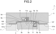
- F 1 and F 2 are tension that acts respectively on the portion 105 and the portion 107 on both sides sandwiching the character-line equivalent portion103
- P is the load ( FIG. 2 ) by which the metal sheet 101 is pressed due to contraction of the die side elastic body 11
- ⁇ e is the friction coefficient between the die side elastic body 11 and the metal sheet 101.
- the load P may be calculated from the amount of contraction upon compression until the die side contact surface portion 11a becomes flush with the die side forming surface portion 5b, and the amount of contraction of the die side elastic body 11 is assumed to be equal to the amount of protrusion of the die side elastic body 11 from the die side forming surface portion 5b.
- the friction coefficient ⁇ e may be measured beforehand by a sliding test, for example. Or, in a case where a rubber material or urethane material is used as the die side elastic body 11 as described later, the friction coefficient ⁇ e generally equals 0.1 to 0.3 (lubricant) or ⁇ e ⁇ 0.5 to 0.6 (dry), and any of these values may thus be used.
- the difference in tension (F 1 - F 2 in Equation (2)) that acts on the portion 105 and the portion 107 on both sides sandwiching the character-line equivalent portion 103 in the process of press forming may be found beforehand by: an experiment in which tension that acts on the metal sheet 101 is actually measured by use of, for example, a strain gauge in the process of press forming to obtain the outer panel 111 of an automobile; or a press forming analysis for the outer panel 111 of an automobile by, for example, a finite element method (FEM).
- FEM finite element method
- the die side elastic body 11 preferably has hardness and a shape that enable the die side elastic body 11 to be deformed along the shape of the press-forming die (the shape of the die side forming surface portion 5b) at the bottom dead center, that is, to be deformed (to contract in the press forming direction) until the die side contact surface portion 11a becomes flush with the die side forming surface portion 5b.
- a specific material for this die side elastic body 11 may be, for example, a rubber material or urethane material having Shore hardness of 40 to 100 HS.
- the press forming method for an outer panel of an automobile is, as illustrated in FIG. 1 , for press forming the metal sheet 101 into the outer panel 111 of an automobile by using the press forming apparatus 1 including the punch 3, the die 5, the blank holder 7, the punch side elastic body 9, and the die side elastic body 11, the outer panel 111 having the character-line 113 and the panel surface portion 115 and the panel surface portion 117 that are continuous on both sides of the character-line 113, and the press forming method includes an elastic body contact step and a press forming step.
- the punch side elastic body 9 is provided in the groove 3d so that the punch side elastic body 9: protrudes toward the die 5 than the punch side forming surface portion 3c; and is thus able to come into contact with the metal sheet 101, along the character-line equivalent portion 103, on the portion 107, at a position away from the character-line equivalent portion 103, the portion 107 being on a side larger in tension in the process of press forming among the portion 105 and the portion 107 on both sides sandwiching the character-line equivalent portion 103 of the metal sheet 101.
- the die side elastic body 11 is provided in the groove 5d so that the die side elastic body 11: protrudes toward the punch 3 than the die side forming surface portion 5b; and thus comes into contact with and press the metal sheet 101 on the portion 105, along the character-line equivalent portion 103, at a position away from the character-line equivalent portion 103, the portion 105 being on a side smaller in tension in the process of press forming among the portion 105 and the portion 107 on both sides sandwiching the character-line equivalent portion 103 of the metal sheet 101.
- Each of the elastic body contact step and the press forming step will be described hereinafter.
- the elastic body contact step is, as illustrated in FIG. 1(a) to FIG. 1(b) , a step of relatively moving the die 5 toward the punch 3 in a state where the end portion 101a and the end portion 101b of the metal sheet 101 are being sandwiched between the die 5 and the blank holder 7, and bringing each of the punch side contact surface portion 9a of the punch side elastic body 9 and the die side contact surface portion 11a of the die side elastic body 11 into contact with the metal sheet 101.
- the punch side elastic body 9 protrudes from the punch side forming surface portion 3c by an amount that has been set so that: the punch side contact surface portion 9a comes into contact with the metal sheet 101 before the ridgeline 3a of the punch 3 contacts the metal sheet 101; and the punch side contact surface portion 9a becomes flush with the punch side forming surface portion 3c at the bottom dead center.
- the die side elastic body 11 protrudes from the die side forming surface portion 5b by an amount that has been set so that: the die side contact surface portion 11a comes into contact with the metal sheet 101 before a portion of the metal sheet 101 is plastically deformed, the portion being where the ridgeline 3a of the punch 3 comes into contact with; and the die side contact surface portion 11a becomes flush with the die side forming surface portion 5b at the bottom dead center.
- the plastic deformation of the metal sheet 101 by the ridgeline 3a may be determined by, for example, the strain ⁇ 0 found by use of Equation (1) mentioned already.
- the amount of protrusion of the die side elastic body 11 is set, as expressed by Equation (2) mentioned already, so that the friction force becomes equal to or larger than the absolute value
- of the difference in tension preferably satisfy Equation (2) mentioned already.
- the press forming step is, as illustrated in FIG. 1(b) to FIG. 1(e) , a step of relatively moving the die 5 toward the punch 3 up to the bottom dead center, with the punch side contact surface portion 9a and the die side contact surface portion 11a maintained in contact with the metal sheet 101, and obtaining the outer panel 111 of an automobile by press forming, the outer panel 111 having the character-line 113 formed therein, by means of the ridgeline 3a and the valley-line 5a.
- the die 5 relatively moves toward the punch 3, the punch side contact surface portion 9a of the punch side elastic body 9 comes into contact with a surface of the portion 107 of the metal sheet 101, the surface being toward the punch 3, before the ridgeline 3a of the punch 3 does, and the die side contact surface portion 11a of the die side elastic body 11 also comes into contact with a surface of the portion 105, the surface being toward the die 5 ( FIG. 1(a) to FIG. 1(b) ).
- the punch side elastic body 9 supports the portion 107 by being deformed while being in contact with the portion 107, and a portion extending from the character-line equivalent portion 103 to the portion 107 of the metal sheet 101 thereby gradually undergoes bending deformation to be formed into a gently curved shape ( FIG. 1(c) ). Therefore, even if the ridgeline 3a happens to come into contact with a portion of the metal sheet 101, generation of an initial bending defective resulting from plastic deformation of that portion is able to be prevented.
- the character-line 113 is formed by the ridgeline 3a of the punch 3 and the valley-line 5a of the die 5
- the panel surface portion 117 is formed by deformation of the punch side contact surface portion 9a of the punch side elastic body 9, the deformation being deformation in which the punch side contact surface portion 9a becomes flush with the punch side forming surface portion 3c
- the panel surface portion 115 is formed by deformation of the die side contact surface portion 11a of the die side elastic body 11, the deformation being deformation in which the die side contact surface portion 11a becomes flush with the die side forming surface portion 5b ( FIG. 1(e) ).
- a punch side elastic body 9 may be provided in a groove 3d via a punch side movable body 23, and a die side elastic body 11 may be provided in a groove 5d via a die side movable body 25.
- FIG. 3(a) is a state before forming is started
- FIG. 3(b) is a state where the punch side elastic body 9 and the die side elastic body 11 are in contact with a metal sheet 101
- FIG. 3(c) is a state where the metal sheet 101 is being supported by the punch side elastic body 9
- FIG. 1(d) is a state where the metal sheet 101 is being pressed by the die side elastic body 11
- FIG. 1(e) is a state at a bottom dead center.
- the same reference signs as those assigned in FIG. 1 will be assigned to any portions that are the same as or any portions that correspond to those of the press forming apparatus 1 illustrated in FIG. 1 .
- the pressure applied by the pressure source 23b of the punch side movable body 23 to the punch side elastic body 9 toward the die 5 is set so that: the punch side elastic body 9 compressed in the process of press forming illustrated in FIG. 3(b) to FIG. 3(e) is pushed back toward the bottom of the groove 3d; and a punch side contact surface portion 9a of the punch side elastic body 9 that has been compressed and deformed (has contracted) becomes flush with the punch side forming surface portion 3c, at the bottom dead center, as illustrated in FIG. 3(e) .
- the amount of protrusion of the punch side elastic body 9 supported by the punch side movable body 23, from the punch side forming surface portion 3c is set, similarly to the first embodiment described already.
- the die side movable body 25 pressures the die side elastic body 11 toward a punch 3 and supports the die side elastic body 11, and includes: a pad 25a to which the die side elastic body 11 is attached, the pad 25a being movable along the press forming direction; and a pressure source 25b that causes pressure to be applied to the pad 25a.
- the pressure source 25b may be, for example, air pressure, oil pressure, or urethane.
- the amount of protrusion of the die side elastic body 11 supported by the die side movable body 25, from the die side forming surface portion 5b is set so that, as expressed by Equation (2) mentioned already, the friction force (the product of the load P and the friction coefficient ⁇ e ) between the die side elastic body 11 and the metal sheet 101 becomes equal to or larger than the absolute value (
- This load P is the load due to the contraction of the die side elastic body 11 that has been compressed.
- the die side elastic body 11 in this other mode of the first embodiment is supported by being pressured by the pressure source 25b of the die side movable body 25 toward the punch 3. Therefore, even in, for example, a case where sufficient friction force is unable to be obtained between the die side elastic body 11 and the metal sheet 101 or a case where the tension difference (F 1 - F 2 ) in the metal sheet 101 becomes large before the load to press the metal sheet 101 by the contraction of the die side elastic body 11 becomes large enough, there is a greater degree of freedom of adjustment of the load by the die side elastic body 11 to press the metal sheet 101, the adjustment being for prevention of skidding of the metal sheet 101, through further application of a load by the pressure source 25b to the pad 25a to which the die side elastic body 11 has been attached.
- the groove 5d is at a position away from the character-line equivalent portion 103 and is in the die side forming surface portion 5b that forms the panel surface portion 115 that is comparatively flat and not high in stress. Therefore, there is no problem of generating a linear defect by contact between a corner of the groove 5d and a portion near the character-line equivalent portion 103, this problem being generated in a case where the groove 5d is provided near the character-line equivalent portion 103 like in the technique described in Patent Literature 7.
- the groove 3d is at a position away from the character-line equivalent portion 103 and is in the punch side forming surface portion 3b that forms the panel surface portion 117 comparatively flat and not high in stress. Therefore, there is no problem of generating the linear defective, the problem being caused in a case where the groove 3d is provided near the character-line equivalent portion 103 like in the technique described in Patent Literature 6.
- the order in which the punch side elastic body 9 and the die side elastic body 11 are brought into contact with the metal sheet 101 is not particularly limited.
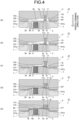
- the die 5 is relatively moved toward the punch 3, the punch side elastic body 9 provided in the punch side forming surface portion 3b comes into contact with the metal sheet 101 on the punch 3 side of the portion 105 before the ridgeline 3a of the punch 3 does, and the die side elastic body 11 provided in the die side forming surface portion 5c comes into contact with the metal sheet 101 on the die 5 side of the portion 107 ( FIG. 4(a) to FIG. (b)).
- friction enables: prevention of skidding of the metal sheet 101 toward the end portion 101b larger in tension; and prevention of misalignment of the character-line equivalent portion 103 plastically deformed by the ridgeline 3a ( FIG. 4(c) to FIG. 4(d) ), the friction being between the metal sheet 101 and the die side elastic body 11 that has come into contact with the portion 107 larger in tension and has been compressed.
- the die 5 is able to be relatively moved to the bottom dead center, with: bending deformation being mitigated by the punch side elastic body 9 over a range from the character-line equivalent portion 103 to the portion 105; and the die side elastic body 11 preventing skidding of the metal sheet 101 toward the end portion 101b larger in tension ( FIG. 4(d) to FIG. 4(e) ).
- the character-line 113 is formed by the ridgeline 3a of the punch 3 and the valley-line 5a of the die 5
- the panel surface portion 115 is formed by deformation of the punch side contact surface portion 9a of the punch side elastic body 9, the deformation being deformation in which the punch side contact surface portion 9a becomes flush with the punch side forming surface portion 3b
- the panel surface portion 117 is formed by deformation of the die side contact surface portion 11a of the die side elastic body 11, the deformation being deformation in which the die side contact surface portion 11a becomes flush with the die side forming surface portion 5c.
- a corner of the groove 3d ( FIG. 4 and FIG. 5 ) to accommodate the punch side elastic body 9 is preferably separate from the ridgeline 3a by a distance that is 10% or more of the width of the punch side forming surface portion 3b, the corner being near the character-line 113.
- a corner of the groove 5d ( FIG. 4 and FIG. 5 ) to accommodate the die side elastic body 11 is preferably separate from a valley-line 5a by a distance that is 10% or more of the width of the die side forming surface portion 5c, the corner being near the character-line 113.
- the order in which the punch side elastic body 9 and the die side elastic body 11 are brought into contact with the metal sheet 101 is not particularly limited.
- a groove to accommodate a punch side elastic body needs to have a width larger than that of the punch side elastic body, to accommodate deformation of the punch side elastic body in the process of press forming.
- a groove to accommodate a die side elastic body needs to have a width larger than that of the die side elastic body, to accommodate deformation of the die side elastic body in the process of press forming.
- Example of the invention a press forming analysis of press forming a metal sheet 101 into an outer panel 121 ( FIG. 6 ) by use of a press forming apparatus 1 including a punch 3, a die 5, a blank holder 7, a punch side elastic body 9, and a die side elastic body 11, like the one illustrated in FIG. 1 , was performed.
- the amount of protrusion of the punch side elastic body 9 from the punch side forming surface portion 3c was set at 5 mm so that the punch side contact surface portion 9a came into contact with the metal sheet 101 before a ridgeline 3a of the punch 3 contacted the metal sheet 101.
- the die side elastic body 11 was provided in a groove 5d in a die side forming surface portion 5b, to protrude toward the punch 3 from the die side forming surface portion 5b.
- the die side elastic body 11 was then caused to come into contact with and to press a portion corresponding to the panel surface portion 125 at a larger acute angle to the press forming direction, the portion being at a position away from the character-line equivalent portion 103 (a boundary of the groove 5d of the die 5 is at a position that is 10% of the width of the die side forming surface portion 5b, the boundary being near the character-line equivalent portion 103).
- FIG. 7 illustrates results for cross-sectional shapes of the outer panels 121 obtained by the press forming analyses.
- FIG. 8 illustrates results of evaluation of surface deflection for the outer panels 121 obtained in the press forming analyses.
- FIG. 8 is a graph having a horizontal axis representing horizontal coordinates of the panel surface portions 127 when the panel surface portions 127 smaller in acute angle to the press forming direction are arranged to be horizontal, and a vertical axis representing the evaluation value ⁇ s for surface deflection at each horizontal position.
- the difference between the maximum and the minimum of the evaluation value ⁇ s of surface deflection was 0.017 in Conventional Example and 0.006 in Example of the invention. It can thereby be understood that the punch side elastic body 9 was brought into contact with the metal sheet 101 and supported the metal sheet 101 so that bending deformation resulted in a gently curved shape, the die side elastic body 11 pressed the metal sheet 101 for press forming, and surface deflection in the panel surface portion 127 was thereby reduced.
- the present invention enables obtainment of an outer panel of an automobile by press forming with skid lines being prevented, the outer panel having a character-line formed therein.
- the present invention enables provision of a press forming method and a press forming apparatus, for outer panels of automobiles, for formation of targeted character-lines, with skid lines being prevented without increase in man-hours for press forming.
Landscapes
- Engineering & Computer Science (AREA)
- Mechanical Engineering (AREA)
- Shaping Metal By Deep-Drawing, Or The Like (AREA)
- Mounting, Exchange, And Manufacturing Of Dies (AREA)
Abstract
Description
- The present invention relates to press forming methods and press forming apparatuses for outer panels of automobiles, the press forming methods and press forming apparatuses being for press forming metal sheets into outer panels of automobiles, the outer panels having character-lines formed therein. With respect to the present invention, a metal sheet refers to a sheet formed of any of various metals, such as stainless steel, aluminum, and magnesium, for example, a hot-rolled steel sheet, a cold - rolled steel sheet, or a surface-treated steel sheet, which is a steel sheet that has been subjected to surface treatment (such as electrogalvanization, hot-dip galvanizing, or organic coating treatment).
- Outer panels of automobiles, the outer panels being used for, for example, door outers, front fenders, or rear fenders, of automobiles, often have character-lines formed on outer surfaces thereof, in terms of improving designability and tensile rigidity of the automobiles. These character-lines are normally formed by pressing a metal sheet (blank) against a ridgeline provided on a punch of press-forming dies and holding the metal sheet between the ridgeline and a valley-line of a die. In particular, in recent years, to further improve designability of automobiles, there is a demand for formation of character-lines that are sharp (that is, large in curvature (small in curvature radius) of ridgelines).
- In this type of press forming, a linear pattern may be generated by contact between a ridgeline of a punch and a portion other than a portion where a character-line is supposed to be formed. This linear pattern will still remain after coating and will become an appearance defect called a skid line defect in the outer panel. Such skid line defects act as a constraint on improvement in designability of automobiles because a skid line defect becomes particularly noticeable in a case where press forming is performed by use of a punch having a ridgeline with a distal end formed of a small circular arc having a small radius of section in an attempt to form a sharp character-line.
- Some techniques for forming character-lines by minimizing generation of such linear patterns have been proposed thus far.
- For example, in a method disclosed in
Patent Literature 1, a forming auxiliary cross-sectional shape of a design recess portion is provided in a die and a blank holder, the periphery of a blank is held therebetween, a central portion of the blank is thereby caused to undergo bending deformation beforehand along a forming surface of a punch, and thereafter the blank is subjected to forming by use of a punch and a design surface is formed thereon. In a method disclosed inPatent Literature 2, a suction port is formed on a press surface where a linear convex portion for forming a character-line is provided, press forming is performed by adhesion of a metal sheet to the press surface by use of a suction device that implements suction via a gas flow path from the suction port, and movement of the metal sheet is thereby minimized and skid lines are prevented. In a technique disclosed inPatent Literature 3, a steel sheet is subjected to primary forming by means of a punch angle and a cushion pad, deep drawing and stretch forming are thereafter performed while the punch is lowered, and formation of a skid line in a portion of a metal sheet is thereby prevented, the portion being where the punch angle has come into contact with. - In a technique disclosed in
Patent Literature 4, in manufacturing a press formed part having a ridgeline, skid lines are prevented and a high quality press formed part is obtained, through a first press forming process of forming a preforming shape and a second press forming process of further forming the preforming shape. In a technique disclosed inPatent Literature 5, an elastic body is provided at a distal end portion of a punch, bending tendency due to initial contact by the punch is minimized, shifting of any generated bending tendency from a character-line is also minimized, and skid lines upon forming of the character-line are thereby minimized. In a technique disclosed inPatent Literature 6, a character-line is formed in a blank by means of a die pad formed of an elastic body and a distal end portion of a punch, and a portion other than the character-line is formed by means of a die and a punch, with the formed character-line still being restricted by the die pad and the punch. In a technique disclosed inPatent Literature 7, a plate-shaped workpiece is pressed against a lower die having a convex R portion for forming a character-line, the workpiece is brought into contact with a press pad, at a position near the convex R portion after the workpiece has held the convex R portion, and skidding of the workpiece is thereby minimized. -
- Patent Literature 1:
Japanese Patent No. 5876786 - Patent Literature 2:
Japanese Unexamined Patent Application, Publication No. 2015-199102 - Patent Literature 3:
Japanese Examined Patent Publication No. S63-058652 - Patent Literature 4:
Japanese Patent No. 5959702 - Patent Literature 5:
Japanese Unexamined Patent Application, Publication No. 2018-103249 - Patent Literature 6:
Japanese Unexamined Patent Application, Publication No. 2018-158351 - Patent Literature 7:
Japanese Unexamined Patent Application, Publication No. 2018-183786 - However, the techniques disclosed in
Patent Literature 1 toPatent Literature 7 have the following problems. - In the technique disclosed in
Patent Literature 1, deformation by the die and the blank holder provided with the forming auxiliary cross-sectional shape is not restricted by the punch, only both end portions of the blank corresponding to the design recess portion are able to be restricted, and the bending deformation is thus limited to straight-lined shapes. The technique disclosed inPatent Literature 2 has problems in that the suction device not used in normal press forming is needed and the shape of the suction port is transferred onto a surface of the formed part. The technique disclosed inPatent Literature 3 has problems in that the final product shape is partially formed in the process of forming, and surface deflection occurs at the boundary of the forming incomplete portion. - The technique disclose in
Patent Literature 4 has problems in that the die for forming the preforming shape is different from the die for forming the targeted shape, and the number of processes including the process of switching the dies is increased. The technique disclosed inPatent Literature 5 has problems in that a shape just like the shape of the ridgeline is unable to be formed because the convex side of the ridgeline is formed by the elastic body. The technique disclosed inPatent Literature 6 has problems in that in a case where plural character-lines are near each other, the character-lines are unable to be formed just like the targeted shape, because the character-lines are formed by means of a die pad formed of an elastic body. The technique disclosed inPatent Literature 7 has problems in that in a case where the form of a surface is complex, the appropriate time to bring a press pad into contact with a workpiece is unable to be set and a defective is generated on the workpiece by the press pad. - The present invention has been made in view of the above described problems and an object of the present invention is to provide a press forming method and a press forming apparatus that are for outer panels of automobiles, the press forming method and press forming apparatus enabling: prevention of skid lines without increase in man-hours for press forming; and formation of character-lines targeted.
- To solve the problem and achieve the object, a press forming method for an outer panel of an automobile according to the present invention is the press forming method for press forming a metal sheet into the outer panel of the automobile, the outer panel having a character-line and a panel surface portion that is continuous on both sides of the character-line, by using a punch, a die facing the punch, and a blank holder facing end portions of the die, wherein the punch includes: a ridgeline to form the character-line; a punch side forming surface portion to form the panel surface portion; and a punch side elastic body supported to protrude toward the die than the punch side forming surface portion so that the punch side elastic body is able to come into contact with the metal sheet, along a character-line equivalent portion corresponding to the character-line in the metal sheet, at a position away from the character-line equivalent portion, on a side larger in tension in the press forming among portions on both sides sandwiching the character-line equivalent portion, and the die includes: a valley-line to form the character-line in cooperation with the ridgeline; a die side forming surface portion to form the panel surface portion; and a die-side elastic body supported to protrude toward the punch than the die side forming surface portion so that the die side elastic body comes into contact with and press the metal sheet, along the character-line equivalent portion, at a position away from the character-line equivalent portion, on a side smaller in tension in the press forming among portions on both sides sandwiching the character-line equivalent portion, the press forming method comprising: an elastic body contact step of relatively moving the die toward the punch in a state where both end portions of the metal sheet are sandwiched between the die and the blank holder, and bringing each of the punch side elastic body and the die side elastic body into contact with the metal sheet; and a press forming step of press forming the metal sheet into the outer panel of the automobile, the outer panel having the character-line formed by means of the ridgeline and the valley-line, by relatively moving the die toward the punch up to a bottom dead center with the punch side elastic body and the die side elastic body both being in contact with the metal sheet, wherein an amount of protrusion of the punch side elastic body from the punch side forming surface portion is set so that the punch side elastic body: comes into contact with the metal sheet before the ridgeline of the punch contacts the metal sheet at the elastic body contact step; and becomes flush with the punch side forming surface portion at the bottom dead center, and an amount of protrusion of the die side elastic body from the die side forming surface portion is set so that: the die side elastic body comes into contact with the metal sheet before the ridgeline of the punch contacts the metal sheet and the metal sheet is plastically deformed at the elastic body contact step; and a friction force given by a product of: a load of the die side elastic body pressing the metal sheet at the press forming step; and a friction coefficient between the die side elastic body and the metal sheet, becomes equal to or larger than an absolute value of a difference between tensions acting on the portions on both sides sandwiching the character-line equivalent portion.
- Moreover, a press forming method for an outer panel of an automobile according to the present invention is the press forming method for press forming a metal sheet into the outer panel of the automobile, the outer panel having a character-line and a panel surface portion that is continuous on both sides of the character-line, by using a punch, a die facing the punch, and a blank holder facing end portions of the die, wherein the punch includes: a ridgeline to form the character-line; a punch side forming surface portion to form the panel surface portion; and a punch side elastic body supported to protrude toward the die than the punch side forming surface portion so that the punch side elastic body is able to come into contact with the metal sheet, along a character-line equivalent portion corresponding to the character-line in the metal sheet, at a position away from the character-line equivalent portion, on a side smaller in tension in the press forming among portions on both sides sandwiching the character-line equivalent portion, and the die includes: a valley-line to form the character-line in cooperation with the ridgeline; a die side forming surface portion to form the panel surface portion; and a die-side elastic body supported to protrude toward the punch than the die side forming surface portion so that the die side elastic body comes into contact with and press the metal sheet, along the character-line equivalent portion, at a position away from the character-line equivalent portion, on a side larger in tension in the press forming among portions on both sides sandwiching the character-line equivalent portion, the press forming method comprising: an elastic body contact step of relatively moving the die toward the punch in a state where both end portions of the metal sheet are being sandwiched between the die and the blank holder, and bringing each of the punch side elastic body and the die side elastic body into contact with the metal sheet; and a press forming step of press forming the metal sheet into the outer panel of the automobile, the outer panel having the character-line formed by means of the ridgeline and the valley-line, by relatively moving the die toward the punch up to a bottom dead center with the punch side elastic body and the die side elastic body both being in contact with the metal sheet, wherein an amount of protrusion of the punch side elastic body from the punch side forming surface portion is set so that the punch side elastic body: comes into contact with the metal sheet before the ridgeline of the punch contacts the metal sheet; and becomes flush with the punch side forming surface portion at the bottom dead center, and an amount of protrusion of the die side elastic body from the die side forming surface portion is set so that: the die side elastic body comes into contact with the metal sheet before the ridgeline of the punch contacts the metal sheet and the metal sheet is plastically deformed at the elastic body contact step; and a friction force given by a product of: a load of the die side elastic body pressing the metal sheet at the press forming step; and a friction coefficient between the die side elastic body and the metal sheet, becomes equal to or larger than an absolute value of a difference between tensions acting on the portions on both sides sandwiching the character-line equivalent portion.
- Moreover, in the press forming method for the outer panel of the automobile according to the present invention, the punch side elastic body is movable along a press forming direction and is provided in the punch via a punch side movable body that supports the punch side elastic body by pressuring the punch side elastic body toward the die.
- Moreover, in the press forming method for the outer panel of the automobile according to the present invention, the die side elastic body is movable along a press forming direction and is provided in the die via a die side movable body that supports the die side elastic body by pressuring the die side elastic body toward the punch.
- Moreover, a press forming apparatus for an outer panel of an automobile according to the present invention is the press forming apparatus for press forming a metal sheet into the outer panel of the automobile, the outer panel having a character-line and a panel surface portion that is continuous on both sides of the character-line, by using a punch, a die facing the punch, and a blank holder facing end portions of the die, wherein the punch includes: a ridgeline to form the character-line; a punch side forming surface portion to form the panel surface portion; and a punch side elastic body supported to protrude toward the die than the punch side forming surface portion so that the punch side elastic body is able to come into contact with the metal sheet, along a character-line equivalent portion corresponding to the character-line in the metal sheet, at a position away from the character-line equivalent portion, on a side larger in tension in the press forming among portions on both sides sandwiching the character-line equivalent portion, and the die includes: a valley-line to form the character-line in cooperation with the ridgeline; a die side forming surface portion to form the panel surface portion; and a die-side elastic body supported to protrude toward the punch than the die side forming surface portion so that the die side elastic body comes into contact with and press the metal sheet, along the character-line equivalent portion, at a position away from the character-line equivalent portion, on a side smaller in tension in the press forming among portions on both sides sandwiching the character-line equivalent portion, wherein an amount of protrusion of the punch side elastic body from the punch side forming surface portion is set so that the punch side elastic body: comes into contact with the metal sheet before the ridgeline of the punch contacts the metal sheet when the die is relatively moved toward the punch; and becomes flush with the punch side forming surface portion at a bottom dead center, and an amount of protrusion of the die side elastic body from the die side forming surface portion is set so that: the die side elastic body comes into contact with the metal sheet before the ridgeline of the punch contacts the metal sheet and the metal sheet is plastically deformed when the die is relatively moved toward the punch; and a friction force being given by a product of: a load of the die side elastic body pressing the metal sheet; and a friction coefficient between the die side elastic body and the metal sheet, becomes equal to or larger than an absolute value of a difference between tensions acting on the portions on both sides sandwiching the character-line equivalent portion.
- Moreover, a press forming apparatus for an outer panel of an automobile according to the present invention is the press forming apparatus for press forming a metal sheet into the outer panel of the automobile, the outer panel having a character-line and panel surface portion that is continuous on both sides of the character-line, by using a punch, a die facing the punch, and a blank holder facing end portions of the die, wherein the punch includes: a ridgeline to form the character-line; a punch side forming surface portion to form the panel surface portion; and a punch side elastic body supported to protrude toward the die than the punch side forming surface portion so that the punch side elastic body is able to come into contact with the metal sheet, along a character-line equivalent portion corresponding to the character-line in the metal sheet, at a position away from the character-line equivalent portion, on a side smaller in tension in the press forming among portions on both sides sandwiching the character-line equivalent portion, and the die includes: a valley-line to form the character-line in cooperation with the ridgeline; a die side forming surface portion to form the panel surface portion; and a die-side elastic body supported to protrude toward the punch than the die side forming surface portion so that the die side elastic body comes into contact with and press the metal sheet, along the character-line equivalent portion, at a position away from the character-line equivalent portion, on a side larger in tension in the press forming among portions on both sides sandwiching the character-line equivalent portion, wherein an amount of protrusion of the punch side elastic body from the punch side forming surface portion is set so that the punch side elastic body: comes into contact with the metal sheet before the ridgeline of the punch contacts the metal sheet when the die is relatively moved toward the punch; and becomes flush with the punch side forming surface portion at a bottom dead center, and an amount of protrusion of the die side elastic body from the die side forming surface portion is set so that: the die side elastic body comes into contact with the metal sheet before the ridgeline of the punch contacts the metal sheet and the metal sheet is plastically deformed when the die is relatively moved toward the punch; and a friction force being given by a product of: a load of the die side elastic body pressing the metal sheet; and a friction coefficient between the die side elastic body and the metal sheet, becomes equal to or larger than an absolute value of a difference between tensions acting on the portions on both sides sandwiching the character-line equivalent portion.
- Moreover, in the press forming apparatus for the outer panel of the automobile according to the present invention, the punch side elastic body is movable along a press forming direction and is provided in the punch via a punch side movable body that supports the punch side elastic body by pressuring the punch side elastic body toward the die.
- Moreover, in the press forming apparatus for the outer panel of the automobile according to the present invention, the die side elastic body is movable along a press forming direction and is provided in the die via a die side movable body that supports the die side elastic body by pressuring the die side elastic body toward the punch.
- The present invention enables: prevention of generation of a bending defective in a metal sheet due to a ridgeline of a punch, by bringing a punch side elastic body caused to protrude from a punch side forming surface portion, into contact with the metal sheet, to support the metal sheet, at a position away from a character-line equivalent portion, in the process of press forming the metal sheet into an outer panel of an automobile by use of the punch having the ridgeline, a die facing the punch and having a valley-line, and a blank holder facing end portions of the die, the outer panel having a character-line and a panel surface portion continuous on both sides of the character-line, the character-line being formed by the ridgeline and the valley-line; prevention of skidding of the metal sheet due to a difference in tension acting on both sides of the character-line equivalent portion of the metal sheet, by bringing a die side elastic body caused to protrude from a die side forming surface portion, into contact with the metal sheet, to press the metal sheet, at a position opposite to the punch side elastic body and away from the character-line equivalent portion, and thereby making a friction force larger than the difference in tension, the friction force being between the metal sheet and the die side elastic body caused to protrude from the die side forming surface portion and to be compressed; and thus obtainment of the outer panel of the automobile by press forming, the outer panel having the character-line formed therein, with skid lines being reduced.
-
-
FIG. 1 is a diagram illustrating a press forming method and a configuration of a press forming apparatus, for outer panels of automobiles, according to a first embodiment of the present invention. -
FIG. 2 is a diagram illustrating a load P to press a metal sheet by means of a die side elastic body that has been compressed and tension F1 and tension F2 generated in the metal sheet, in the process of press forming by the press forming method and press forming apparatus for outer panels of automobiles, according to the first embodiment of the present invention. -
FIG. 3 is a diagram illustrating a press forming method and a configuration of a press forming apparatus, for outer panels of automobiles, according to another mode of the first embodiment of the present invention. -
FIG. 4 is a diagram illustrating a press forming method and a configuration of a press forming apparatus, for outer panels of automobiles, according to a second embodiment of the present invention. -
FIG. 5 is a diagram illustrating a press forming method and a configuration of a press forming apparatus, for outer panels of automobiles, according to another mode of the second embodiment of the present invention. -
FIG. 6 is a diagram illustrating an outer panel to be formed in Examples, and arrangement upon evaluation of the shape of and any skid line in a panel surface portion of the outer panel. -
FIG. 7 is a diagram illustrating results for cross-sectional shapes of outer panels, the results having been found by press forming analyses, in Examples. -
FIG. 8 is a diagram illustrating results for evaluation values Δs for surface deflection of the outer panels, the results having been found by the press forming analyses, in Examples. -
FIG. 9 is a diagram illustrating operation in a conventional press forming method and of a conventional press forming apparatus, for outer panels of automobiles, and a skid line generated in the process of press forming. Description of Embodiments - A skid line generated in press forming for an outer panel of an automobile, the outer panel having a character-line, will be described, before description of press forming methods and press forming apparatuses for outer panels of automobiles, according to a first embodiment and a second embodiment of the present invention.
- An
outer panel 111 of an automobile, theouter panel 111 being targeted in the present invention, has, for example, as illustrated inFIG. 9(d) , a character-line 113 and apanel surface portion 115 and apanel surface portion 117 that are continuous on both sides of the character-line 113, and is obtained by deep drawing as follows by use of apress forming apparatus 51 including apunch 53 having aridgeline 53a extending in a direction perpendicular to the plane of paper ofFIG. 9(d) , a die 55 having a valley-line 55a extending in the direction perpendicular to the plane of paper, and ablank holder 57 facing to both of end portions of the die 55. - First, as illustrated in
FIG. 9(a) , each of anend portion 101a and anend portion 101b of ametal sheet 101 is sandwiched between the die 55 and theblank holder 57. With themetal sheet 101 still being sandwiched therebetween, as illustrated inFIG. 9(a) to FIG. 9(d) , thedie 55 and theblank holder 57 are relatively moved toward thepunch 53 up to a bottom dead center and theouter panel 111 of an automobile is obtained by press forming, theouter panel 111 having the character-line 113 formed therein by means of theridgeline 53a of thepunch 53 and the valley-line 55a of the die 55. - In the process of this press forming, the relative movement of the
die 55 toward thepunch 53 first causes theridgeline 53a of thepunch 53 to come into contact with themetal sheet 101 and causes initial bending in the metal sheet 101 (FIG. 9(b) ). In the process of deep drawing by means of thedie 55 and thepunch 53, tension is generated in the metal sheet 101 (FIG. 9(b) and FIG. 9(c) ) in directions toward theend portion 101a and theend portion 101b from the initial bending defective therebetween. - Magnitudes of the tension generated on both sides of the initial bending defective in the
metal sheet 101 differ from each other depending on: distances from the initial bending defective to theend portion 101a and theend portion 101b and angles of thepanel surface portion 115 and the panel surface portion 117 (FIG. 9(d) ) to a press forming direction; or a difference between, for example, forming direction depths from theridgeline 53a to theend portion 101a and theend portion 101b, the forming direction depths depending on those distances and angles. - For example, in a case where an acute angle of the
panel surface portion 115 with reference to a line drawn in the press forming direction from theridgeline 53a of thepunch 53 is θa, an acute angle of thepanel surface portion 117 to the line is θb, and the angle θb of thepanel surface portion 117 is smaller than the angle θa of the panel surface portion 115 (seeFIG. 9(d) ), the tension generated toward theend portion 101b (a portion 107) of themetal sheet 101 becomes larger than the tension generated toward theend portion 101a (a portion 105) of themetal sheet 101 in the process of press forming (FIG. 9(b) and FIG. 9(c) ). - In response to generation of a difference in tension between these portions on both sides of the initial bending defective, skidding toward the portion larger in tension is caused in the
metal sheet 101 and the initial bending defective is displaced toward theend portion 101b larger in tension (FIG. 9(c) ). The initial bending defective is then squashed by thepunch 53 and the die 55 at the bottom dead center and a linear pattern, that is, a skid line, is generated (FIG. 9(d) ). - As described above, a skid line in the
outer panel 111 of an automobile, theouter panel 111 having the character-line 113 formed therein, is caused by imbalanced tension generated in themetal sheet 101 in the process of deep drawing. Examples of causes of imbalanced tension include, as described already, a difference between forming depths of theend portion 101a and theend portion 101b of themetal sheet 101, the difference being due to differences between distances and angles from the portion with which theridgeline 53a of thepunch 53 comes into contact to theend portion 101a and theend portion 101b of themetal sheet 101. - That is, in a case where the
end portion 101a and theend portion 101b of themetal sheet 101 have different forming depths, tension generated toward theend portion 101b larger in forming depth becomes larger, and due to the tension difference from that toward theend portion 101a smaller in forming depth, themetal sheet 101 skids toward theend portion 101b and a skid line is generated. - The press forming methods and the press forming apparatuses for outer panels of automobiles, according to the first embodiment and the second embodiment of the present invention will be described next. The same reference sign will be assigned to components having the same or corresponding functions and redundant description thereof will be avoided, in the description hereinafter.
- For example, as illustrated in
FIG. 1 , apress forming apparatus 1 for outer panels of automobiles (hereinafter, simply referred to as the "press forming apparatus 1"), according to the first embodiment is for press forming ametal sheet 101 into an outer panel of an automobile, the outer panel having a character-line 113 and apanel surface portion 115 and apanel surface portion 117 that are continuous on both sides of the character-line 113, and thepress forming apparatus 1 includes apunch 3, adie 5, ablank holder 7, a punch sideelastic body 9, and a die sideelastic body 11. -
FIG. 1(a) is a state before forming is started,FIG. 1(b) is a state where the punch sideelastic body 9 and the die sideelastic body 11 are in contact with themetal sheet 101,FIG. 1(c) is a state where themetal sheet 101 is being supported by the punch sideelastic body 9,FIG. 1(d) is a state where themetal sheet 101 is being pressed by the die sideelastic body 11, andFIG. 1(e) is a state at a bottom dead center. - Furthermore, for an
outer panel 111 of an automobile (FIG. 1(e) ), theouter panel 111 being a target to be formed in this first embodiment, as illustrated inFIG. 9 described already, it is assumed that tension generated toward anend portion 101b from a boundary that is a character-lineequivalent portion 103 in themetal sheet 101 is larger than tension generated toward anend portion 101a from the boundary, in the process of press forming (seeFIG. 2 ). - The
punch 3 has, as illustrated inFIG. 1 : aridgeline 3a; a punch side formingsurface portion 3b and a punch side formingsurface portion 3c that are positioned on both sides of theridgeline 3a with theridgeline 3a interposed therebetween; and agroove 3d. - The
ridgeline 3a is to form the character-line 113 (FIG. 1(e) ). - The punch side forming
surface portion 3b and the punch side formingsurface portion 3c are to respectively form thepanel surface portion 115 and the panel surface portion 117 (FIG. 1(e) ). The punch side formingsurface portion 3b is to form aportion 105 smaller in tension acting on themetal sheet 101, into the panel surface portion 115 (FIG. 1(e) ) in the process of press forming. The punch side formingsurface portion 3c, on the other hand, is to form aportion 107 larger in tension acting on themetal sheet 101, into the panel surface portion 117 (FIG. 1(e) ) in the process of press forming. - The
groove 3d has been formed to be concave in the punch side formingsurface portion 3c and has the punch sideelastic body 9 provided therein. - The
die 5 has , as illustrated inFIG. 1 : a valley-line 5a; a die side formingsurface portion 5b and a die side formingsurface portion 5c that are continuous on both sides of the valley-line 5a with the valley-line 5a interposed therebetween; and agroove 5d. - The valley-
line 5a is to form the character-line 113, in cooperation with theridgeline 3a of thepunch 3. - The die side forming
surface portion 5b is to form, in cooperation with the punch side formingsurface portion 3b, thepanel surface portion 115, and the die side formingsurface portion 5c is to form, in cooperation with the punch side formingsurface portion 3c, thepanel surface portion 117. - The die side forming
surface portion 5b is to form theportion 105 smaller in tension acting on themetal sheet 101, into thepanel surface portion 115, in the process of press forming. The die side formingsurface portion 5c, on the other hand, is to form theportion 107 larger in tension acting on themetal sheet 101, into thepanel surface portion 117, in the process of press forming. - The
groove 5d has been formed to be concave in the die side formingsurface portion 5b and has the die sideelastic body 11 provided therein. - As illustrated in
FIG. 1 , theblank holder 7 is arranged to be facing both end portions of thedie 5, and sandwiches, in cooperation with thedie 5, theend portion 101a and theend portion 101b of themetal sheet 101 therebetween. - As illustrated in
FIG. 1 , the punch sideelastic body 9 is theportion 107 larger in tension in the process of press forming, theportion 107 being of theportion 105 and theportion 107 on both sides sandwiching the character-lineequivalent portion 103 corresponding to the character-line 113 in themetal sheet 101. Furthermore, the punch side elastic body 9: is provided in thegroove 3d so that the punch sideelastic body 9 protrudes toward thedie 5 than the punch side formingsurface portion 3c and is able to come into contact, along the character-lineequivalent portion 103, at a position away from the character-lineequivalent portion 103; and has a punch sidecontact surface portion 9a that comes into contact with themetal sheet 101. - The punch side
elastic body 9 protrudes from the punch side formingsurface portion 3c by an amount that has been set so that in relative movement of thedie 5 toward thepunch 3, the punch sidecontact surface portion 9a of the punch sideelastic body 9 comes into contact with themetal sheet 101 before theridgeline 3a of thepunch 3 contacts themetal sheet 101. - The punch side
elastic body 9 preferably has hardness and a shape that: moderate the bending shape of themetal sheet 101, the bending shape being made by theridgeline 3a, in a state where the punch sideelastic body 9 protrudes from the punch side formingsurface portion 3c and is in contact with themetal sheet 101 to support themetal sheet 101, until the bottom dead center is reached; and enable the punch sideelastic body 9 to be deformed along the shape of the press-forming die (the shape of the punch side formingsurface portion 3c) at the bottom dead center (FIG. 1(e) ), that is, to be deformed (to contract in a press forming direction) until the punch sidecontact surface portion 9a becomes flush with the punch side formingsurface portion 3c. A specific material for this punch sideelastic body 9 may be, for example, a rubber material or urethane material, having Shore hardness of 40 to 100 HS. - The die side elastic body 11: is provided to protrude toward the
punch 3 than the die side formingsurface portion 5b so that the die sideelastic body 11 comes into contact with and press themetal sheet 101 on theportion 105, along the character-lineequivalent portion 103, at a position away from the character-lineequivalent portion 103, theportion 105 being on a side smaller in tension in the process of press forming among theportion 105 and theportion 107 on both sides of the character-lineequivalent portion 103 of themetal sheet 101; and has a die sidecontact surface portion 11a that comes into contact with themetal sheet 101. - The die side
elastic body 11 protrudes from the die side formingsurface portion 5b by an amount that has been set so that in relative movement of thedie 5 toward thepunch 3, the die sidecontact surface portion 11a comes into contact with themetal sheet 101, before theridgeline 3a of thepunch 3 comes into contact with themetal sheet 101 and themetal sheet 101 is plastically deformed. This amount of protrusion has been set so that friction force between the die sideelastic body 11 and themetal sheet 101 is equal to or larger than an absolute value of a difference in tension that acts on theportion 105 and theportion 107 on both sides sandwiching the character-lineequivalent portion 103, the friction force being given by the product of: the load by which theportion 105 of themetal sheet 101 is pressed by contraction of the die sideelastic body 11 compressed in the process of press forming; and the friction coefficient between the die side elastic body 11 (die sidecontact surface portion 11a) and themetal sheet 101. - The plastic deformation of the
metal sheet 101 by theridgeline 3a may be determined to be caused, for example, when the strain on a portion of themetal sheet 101 exceeds a strain ε0 calculated by Equation (1) below, the portion being where theridgeline 3a has come into contact with.

- Herein, R is the curvature radius of bending of the character-
line 113 and t is the thickness of themetal sheet 101. - Furthermore, the friction force between the die side
elastic body 11 and themetal sheet 101 is set to satisfy Equation (2) below.

- Herein, as illustrated in
FIG. 2 , F1 and F2 are tension that acts respectively on theportion 105 and theportion 107 on both sides sandwiching the character-line equivalent portion103, P is the load (FIG. 2 ) by which themetal sheet 101 is pressed due to contraction of the die sideelastic body 11, and µe is the friction coefficient between the die sideelastic body 11 and themetal sheet 101. - The load P may be calculated from the amount of contraction upon compression until the die side
contact surface portion 11a becomes flush with the die side formingsurface portion 5b, and the amount of contraction of the die sideelastic body 11 is assumed to be equal to the amount of protrusion of the die sideelastic body 11 from the die side formingsurface portion 5b. - The friction coefficient µe may be measured beforehand by a sliding test, for example. Or, in a case where a rubber material or urethane material is used as the die side
elastic body 11 as described later, the friction coefficient µe generally equals 0.1 to 0.3 (lubricant) or µe ≈ 0.5 to 0.6 (dry), and any of these values may thus be used. - The difference in tension (F1 - F2 in Equation (2)) that acts on the
portion 105 and theportion 107 on both sides sandwiching the character-lineequivalent portion 103 in the process of press forming may be found beforehand by: an experiment in which tension that acts on themetal sheet 101 is actually measured by use of, for example, a strain gauge in the process of press forming to obtain theouter panel 111 of an automobile; or a press forming analysis for theouter panel 111 of an automobile by, for example, a finite element method (FEM). - The die side
elastic body 11 preferably has hardness and a shape that enable the die sideelastic body 11 to be deformed along the shape of the press-forming die (the shape of the die side formingsurface portion 5b) at the bottom dead center, that is, to be deformed (to contract in the press forming direction) until the die sidecontact surface portion 11a becomes flush with the die side formingsurface portion 5b. A specific material for this die sideelastic body 11 may be, for example, a rubber material or urethane material having Shore hardness of 40 to 100 HS. - The press forming method for an outer panel of an automobile, according to the first embodiment is, as illustrated in
FIG. 1 , for press forming themetal sheet 101 into theouter panel 111 of an automobile by using thepress forming apparatus 1 including thepunch 3, thedie 5, theblank holder 7, the punch sideelastic body 9, and the die sideelastic body 11, theouter panel 111 having the character-line 113 and thepanel surface portion 115 and thepanel surface portion 117 that are continuous on both sides of the character-line 113, and the press forming method includes an elastic body contact step and a press forming step. - The punch side
elastic body 9 is provided in thegroove 3d so that the punch side elastic body 9: protrudes toward thedie 5 than the punch side formingsurface portion 3c; and is thus able to come into contact with themetal sheet 101, along the character-lineequivalent portion 103, on theportion 107, at a position away from the character-lineequivalent portion 103, theportion 107 being on a side larger in tension in the process of press forming among theportion 105 and theportion 107 on both sides sandwiching the character-lineequivalent portion 103 of themetal sheet 101. - As described already, the die side
elastic body 11 is provided in thegroove 5d so that the die side elastic body 11: protrudes toward thepunch 3 than the die side formingsurface portion 5b; and thus comes into contact with and press themetal sheet 101 on theportion 105, along the character-lineequivalent portion 103, at a position away from the character-lineequivalent portion 103, theportion 105 being on a side smaller in tension in the process of press forming among theportion 105 and theportion 107 on both sides sandwiching the character-lineequivalent portion 103 of themetal sheet 101. Each of the elastic body contact step and the press forming step will be described hereinafter. - The elastic body contact step is, as illustrated in
FIG. 1(a) to FIG. 1(b) , a step of relatively moving thedie 5 toward thepunch 3 in a state where theend portion 101a and theend portion 101b of themetal sheet 101 are being sandwiched between thedie 5 and theblank holder 7, and bringing each of the punch sidecontact surface portion 9a of the punch sideelastic body 9 and the die sidecontact surface portion 11a of the die sideelastic body 11 into contact with themetal sheet 101. - The punch side
elastic body 9 protrudes from the punch side formingsurface portion 3c by an amount that has been set so that: the punch sidecontact surface portion 9a comes into contact with themetal sheet 101 before theridgeline 3a of thepunch 3 contacts themetal sheet 101; and the punch sidecontact surface portion 9a becomes flush with the punch side formingsurface portion 3c at the bottom dead center. - The die side
elastic body 11 protrudes from the die side formingsurface portion 5b by an amount that has been set so that: the die sidecontact surface portion 11a comes into contact with themetal sheet 101 before a portion of themetal sheet 101 is plastically deformed, the portion being where theridgeline 3a of thepunch 3 comes into contact with; and the die sidecontact surface portion 11a becomes flush with the die side formingsurface portion 5b at the bottom dead center. The plastic deformation of themetal sheet 101 by theridgeline 3a may be determined by, for example, the strain ε0 found by use of Equation (1) mentioned already. - Furthermore, the amount of protrusion of the die side
elastic body 11 is set, as expressed by Equation (2) mentioned already, so that the friction force becomes equal to or larger than the absolute value |F1 - F2| of the difference between the tension F1 and the tension F2 acting respectively toward theend portion 101a and theend portion 101b sandwiching the character-lineequivalent portion 103 of themetal sheet 101, the friction force being given by the product of: the load P due to contraction (deformation) of the die sideelastic body 11 in the press forming direction, the die sideelastic body 11 having been compressed at the press forming step after the elastic body contact step; and the friction coefficient µe between the die sideelastic body 11 and themetal sheet 101. Herein, the load P, the friction coefficient µe, and the absolute value |F1 - F2| of the difference in tension preferably satisfy Equation (2) mentioned already. - The press forming step is, as illustrated in
FIG. 1(b) to FIG. 1(e) , a step of relatively moving thedie 5 toward thepunch 3 up to the bottom dead center, with the punch sidecontact surface portion 9a and the die sidecontact surface portion 11a maintained in contact with themetal sheet 101, and obtaining theouter panel 111 of an automobile by press forming, theouter panel 111 having the character-line 113 formed therein, by means of theridgeline 3a and the valley-line 5a. - The following description based on
FIG. 1 andFIG. 2 is on why the press forming method and press forming apparatus for outer panels of automobiles, according to the first embodiment enable obtainment of theouter panel 111 of an automobile, with skid lines being prevented. - First, the
die 5 relatively moves toward thepunch 3, the punch sidecontact surface portion 9a of the punch sideelastic body 9 comes into contact with a surface of theportion 107 of themetal sheet 101, the surface being toward thepunch 3, before theridgeline 3a of thepunch 3 does, and the die sidecontact surface portion 11a of the die sideelastic body 11 also comes into contact with a surface of theportion 105, the surface being toward the die 5 (FIG. 1(a) to FIG. 1(b) ). - Subsequently, in response to further relative movement of the
die 5 toward thepunch 3, the punch sideelastic body 9 supports theportion 107 by being deformed while being in contact with theportion 107, and a portion extending from the character-lineequivalent portion 103 to theportion 107 of themetal sheet 101 thereby gradually undergoes bending deformation to be formed into a gently curved shape (FIG. 1(c) ). Therefore, even if theridgeline 3a happens to come into contact with a portion of themetal sheet 101, generation of an initial bending defective resulting from plastic deformation of that portion is able to be prevented. - Thereafter, in the process of further relative movement of the
die 5 toward thepunch 3, the die sideelastic body 11 comes into contact with theportion 105 and is deformed, and presses theportion 105 against the punch side formingsurface portion 3b (FIG. 1(d) ). - In this process, in response to contact of the
ridgeline 3a of thepunch 3 with themetal sheet 101, the tension F1 and tension F2 are respectively generated in directions toward theend portion 101a and theend portion 101b, with the character-line equivalent portion103 of themetal sheet 101 being the boundary between the tension F1 and the tension F2 (FIG. 2 ). Because there is a difference between the tension F1 at theend portion 101a and the tension F2 at theend portion 101b, skidding from theend portion 101a smaller in tension toward theend portion 101b larger in tension may occur in the metal sheet 101 (seeFIG. 9 ). - However, the friction between the die side
elastic body 11 and themetal sheet 101 is able to prevent this skidding of themetal sheet 101 toward theend portion 101a larger in tension and to prevent misalignment of the character-lineequivalent portion 103 plastically deformed by theridgeline 3a (FIG. 1(d) ), the die sideelastic body 11 having come into contact with theportion 105 smaller in tension and having been compressed. - As described above, the
die 5 is able to be relatively moved to the bottom dead center, with: the bending deformation being mitigated by the punch sideelastic body 9, the bending deformation being from the character-lineequivalent portion 103 to theportion 107; and the skidding of themetal sheet 101 being prevented by the die sideelastic body 11, the skidding being toward theend portion 101b larger in tension (FIG. 1(d) to FIG. 1(e) ). - At the bottom dead center, the character-
line 113 is formed by theridgeline 3a of thepunch 3 and the valley-line 5a of thedie 5, thepanel surface portion 117 is formed by deformation of the punch sidecontact surface portion 9a of the punch sideelastic body 9, the deformation being deformation in which the punch sidecontact surface portion 9a becomes flush with the punch side formingsurface portion 3c, and thepanel surface portion 115 is formed by deformation of the die sidecontact surface portion 11a of the die sideelastic body 11, the deformation being deformation in which the die sidecontact surface portion 11a becomes flush with the die side formingsurface portion 5b (FIG. 1(e) ). - As a result, the
outer panel 111 of an automobile is able to be obtained by press forming, theouter panel 111 having the character-line 113 formed therein, with skid lines being prevented. - In the above described press forming method and press forming apparatus for outer panels of automobiles, according to the first embodiment of the present invention, as illustrated in
FIG. 1 , the punch sideelastic body 9 is supported by the bottom of thegroove 3d and the die sideelastic body 11 is supported by the bottom of thegroove 5d. - However, in one other mode of the first embodiment, like a
press forming apparatus 21 illustrated as an example inFIG. 3 , a punch sideelastic body 9 may be provided in agroove 3d via a punch sidemovable body 23, and a die sideelastic body 11 may be provided in agroove 5d via a die sidemovable body 25. -
FIG. 3(a) is a state before forming is started,FIG. 3(b) is a state where the punch sideelastic body 9 and the die sideelastic body 11 are in contact with ametal sheet 101,FIG. 3(c) is a state where themetal sheet 101 is being supported by the punch sideelastic body 9,FIG. 1(d) is a state where themetal sheet 101 is being pressed by the die sideelastic body 11, andFIG. 1(e) is a state at a bottom dead center. InFIG. 3 , for parts of thepress forming apparatus 21, the same reference signs as those assigned inFIG. 1 will be assigned to any portions that are the same as or any portions that correspond to those of thepress forming apparatus 1 illustrated inFIG. 1 . - As illustrated in
FIG. 3 , the punch sidemovable body 23 pressures the punch sideelastic body 9 toward adie 5 and supports the punch sideelastic body 9, and includes: apad 23a to which the punch sideelastic body 9 is attached, thepad 23a being movable along a press forming direction; and apressure source 23b that causes pressure to be applied to thepad 23a. Thepressure source 23b may be, for example, air pressure, oil pressure, or urethane. - The pressure applied by the
pressure source 23b of the punch sidemovable body 23 to the punch sideelastic body 9 toward thedie 5 is set so that: the punch sideelastic body 9 compressed in the process of press forming illustrated inFIG. 3(b) to FIG. 3(e) is pushed back toward the bottom of thegroove 3d; and a punch sidecontact surface portion 9a of the punch sideelastic body 9 that has been compressed and deformed (has contracted) becomes flush with the punch side formingsurface portion 3c, at the bottom dead center, as illustrated inFIG. 3(e) . - The amount of protrusion of the punch side
elastic body 9 supported by the punch sidemovable body 23, from the punch side formingsurface portion 3c is set, similarly to the first embodiment described already. - As illustrated in
FIG. 3 , the die sidemovable body 25 pressures the die sideelastic body 11 toward apunch 3 and supports the die sideelastic body 11, and includes: apad 25a to which the die sideelastic body 11 is attached, thepad 25a being movable along the press forming direction; and apressure source 25b that causes pressure to be applied to thepad 25a. Thepressure source 25b may be, for example, air pressure, oil pressure, or urethane. - The pressure applied by the
pressure source 25b of the die sidemovable body 25 to the die sideelastic body 11 toward thepunch 3 is set so that: the die sideelastic body 11 compressed in the process of press forming illustrated inFIG. 3(b) to FIG. 3(e) is pushed back toward the bottom of thegroove 5d; and a die sidecontact surface portion 11a of the die sideelastic body 11 that has been compressed and deformed (has contracted) becomes flush with a die side formingsurface portion 5b, at the bottom dead center, as illustrated inFIG. 3(e) . - The amount of protrusion of the die side
elastic body 11 supported by the die sidemovable body 25, from the die side formingsurface portion 5b is set so that, as expressed by Equation (2) mentioned already, the friction force (the product of the load P and the friction coefficient µe) between the die sideelastic body 11 and themetal sheet 101 becomes equal to or larger than the absolute value (|F1 - F2|) of the difference in tension acting on both sides sandwiching the character-lineequivalent portion 103. This load P is the load due to the contraction of the die sideelastic body 11 that has been compressed. - The following description is on functions and effects of the press forming method and press forming apparatus for outer panels of automobiles, according to this other mode of the first embodiment.
- In this other mode of the first embodiment, the punch side
elastic body 9 is supported by being pressured by thepressure source 23b of the punch sidemovable body 23 toward thedie 5, as illustrated inFIG. 3 . Therefore, as illustrated inFIG. 3(b) to FIG. 3(d) , even if the punch sideelastic body 9 is deformed (contracts) by relative movement of thedie 5 toward thepunch 3, the punch sideelastic body 9 is able to be brought into contact with themetal sheet 101 and be supported, with the punch sideelastic body 9 still being pressured toward thedie 5. - As compared to the first embodiment (see
FIG. 1 ) described already: adjustment of the pressure by thepressure source 23b that supports the punch sideelastic body 9, in addition to change of the material for and/or the shape and size of the punch sideelastic body 9 causes bending deformation of a portion to result in a gently curved shape, the portion being of themetal sheet 101 and being where theridgeline 3a and the punch sidecontact surface portion 9a of the punch sideelastic body 9 come into contact with; and press forming is thus enabled with a greater degree of freedom for preventing generation of an initial bending defective due to theridgeline 3a. - Furthermore, as illustrated in
FIG. 3 , the die sideelastic body 11 in this other mode of the first embodiment is supported by being pressured by thepressure source 25b of the die sidemovable body 25 toward thepunch 3. Therefore, even in, for example, a case where sufficient friction force is unable to be obtained between the die sideelastic body 11 and themetal sheet 101 or a case where the tension difference (F1 - F2) in themetal sheet 101 becomes large before the load to press themetal sheet 101 by the contraction of the die sideelastic body 11 becomes large enough, there is a greater degree of freedom of adjustment of the load by the die sideelastic body 11 to press themetal sheet 101, the adjustment being for prevention of skidding of themetal sheet 101, through further application of a load by thepressure source 25b to thepad 25a to which the die sideelastic body 11 has been attached. - As described above, the press forming method and press forming apparatus for outer panels of automobiles, according to the other mode of the first embodiment also enable press forming to obtain the
outer panel 111 of an automobile, theouter panel 111 having the character-line 113 formed therein, with skid lines being effectively prevented. - As to the position at which the
metal sheet 101 is pressed by the die sideelastic body 11 in each of the first embodiment and the other mode of the first embodiment, as described already (seeFIG. 1 andFIG. 3 ), the die sideelastic body 11 is to come into contact with and press themetal sheet 1 on theportion 105, along the character-lineequivalent portion 103, at the position away from the character-lineequivalent portion 103. - The
groove 5d is at a position away from the character-lineequivalent portion 103 and is in the die side formingsurface portion 5b that forms thepanel surface portion 115 that is comparatively flat and not high in stress. Therefore, there is no problem of generating a linear defect by contact between a corner of thegroove 5d and a portion near the character-lineequivalent portion 103, this problem being generated in a case where thegroove 5d is provided near the character-lineequivalent portion 103 like in the technique described inPatent Literature 7. - A corner of the
groove 5d to accommodate the die sideelastic body 11 is preferably separate from the valley-line 5a by a distance that is 10% or more of the width of the die side formingsurface portion 5b, the corner being near the character-lineequivalent portion 103. - Similarly, in the first embodiment and the other mode of the first embodiment, the position at which the punch side
elastic body 9 presses themetal sheet 101 is set so that the punch sideelastic body 9 is caused to come into contact with themetal sheet 101 on theportion 107, along the character-lineequivalent portion 103, at a position away from the character-line equivalent portion 103 (FIG. 1 andFIG. 3 ), as described already. - As to this point, if the punch side
elastic body 9 is provided at a position near the character-lineequivalent portion 103 like in the technique described inPatent Literature 7, that position is high in stress and is where the character-line 113 is formed, and the corner of thegroove 3d will thus tend to come into contact with a portion near the character-lineequivalent portion 103 and generate a linear defect. - In contrast, in each of the first embodiment and the other mode of the first embodiment, as illustrated in
FIG. 1 andFIG. 3 , thegroove 3d is at a position away from the character-lineequivalent portion 103 and is in the punch side formingsurface portion 3b that forms thepanel surface portion 117 comparatively flat and not high in stress. Therefore, there is no problem of generating the linear defective, the problem being caused in a case where thegroove 3d is provided near the character-lineequivalent portion 103 like in the technique described inPatent Literature 6. - A corner of the
groove 3d to accommodate the punch sideelastic body 9 is preferably separate from theridgeline 3a by a distance that is 10% or more of the width of the punch side formingsurface portion 3c, the corner being near the character-lineequivalent portion 103. - Furthermore, in press forming the
metal sheet 101 into theouter panel 111 of an automobile as illustrated inFIG. 1 andFIG. 3 according to the first embodiment and the other mode of the first embodiment, the order in which the punch sideelastic body 9 and the die sideelastic body 11 are brought into contact with themetal sheet 101 is not particularly limited. - Specifically, as long as the amount of protrusion of the punch side
elastic body 9 is set so that the punch sideelastic body 9 comes into contact with themetal sheet 101 before theridgeline 3a of thepunch 3 contacts themetal sheet 101 and the amount of protrusion of the die sideelastic body 11 is set so that the die sideelastic body 11 comes into contact with themetal sheet 101 before theridgeline 3a of thepunch 3 contacts themetal sheet 101 and plastic deformation occurs: the punch sideelastic body 9 may come into contact with themetal sheet 101 first; the die sideelastic body 11 may come into contact with themetal sheet 101 first; or the punch sideelastic body 9 and the die sideelastic body 11 may come into contact with themetal sheet 101 at the same time. - In the above described first embodiment of the present invention, as illustrated in
FIG. 1 , in the process of press forming themetal sheet 101 into theouter panel 111 of an automobile, the punch sideelastic body 9 is brought into contact with theportion 107 larger in tension, to support theportion 107, theportion 107 being on one side of a character-lineequivalent portion 103, and the die sideelastic body 11 is brought into contact with theportion 105 smaller in tension to press theportion 105, theportion 105 being on the other side of the character-lineequivalent portion 103. - By contrast, in the press forming apparatus and press forming method for outer panels of automobiles, according to the second embodiment of the present invention, like in a
press forming apparatus 31 illustrated as an example inFIG. 4 , in the process of press forming ametal sheet 101 into anouter panel 111 of an automobile, a punch sideelastic body 9 is brought into contact with aportion 105 of themetal sheet 101, to support theportion 105, theportion 105 being smaller in tension, and a die sideelastic body 11 is brought into contact with aportion 107 of themetal sheet 101, to press theportion 107, theportion 107 being larger in tension. -
FIG. 4(a) is a state before forming is started,FIG. 4(b) is a state where the punch sideelastic body 9 and the die sideelastic body 11 are in contact with themetal sheet 101,FIG. 4(c) is a state where themetal sheet 101 is being supported by the punch sideelastic body 9,FIG. 4(d) is a state where themetal sheet 101 is being pressed by the die sideelastic body 11, andFIG. 4(e) is a state at a bottom dead center. InFIG. 4 , for parts of thepress forming apparatus 31, the same reference signs as those assigned inFIG. 1 will be assigned to any portions that are the same as and any portions that correspond to those of thepress forming apparatus 1 illustrated inFIG. 1 . - As illustrated in
FIG. 4 , the punch sideelastic body 9 is provided in thegroove 3d so that the punch sideelastic body 9 protrudes toward adie 5 than a punch side formingsurface portion 3b and is thus able to come into contact with themetal sheet 101 on theportion 105, along the character-lineequivalent portion 103, at a position away from the character-lineequivalent portion 103. - As illustrated in
FIG. 4 , the die sideelastic body 11 is provided in thegroove 5d so that the die sideelastic body 11 protrudes toward thepunch 3 than a die side formingsurface portion 5c and thus comes into contact with and press themetal sheet 101 on theportion 107, along the character-lineequivalent portion 103, at a position away from the character-lineequivalent portion 103. - The amount of protrusion of the punch side
elastic body 9 from the punch side formingsurface portion 3b and the amount of protrusion of the die sideelastic body 11 from the die side formingsurface portion 5c are respectively set, similarly to those in the first embodiment described already. - As illustrated in
FIG. 4 , the press forming method for outer panels of automobiles, according to the second embodiment is, similarly to the first embodiment illustrated inFIG. 1 , for press forming themetal sheet 101 into theouter panel 111 of an automobile, theouter panel 111 having a character-line 113 and apanel surface portion 115 and apanel surface portion 117 continuous on both sides of the character-line 113, by using thepress forming apparatus 31 including thepunch 3, thedie 5, ablank holder 7, the punch sideelastic body 9, and the die sideelastic body 11, and the press forming method includes an elastic body contact step and a press forming step. - The elastic body contact step is, as illustrated in
FIG. 4(a) to FIG. 4(b) , a step of relatively moving thedie 5 toward thepunch 3 in a state where anend portion 101a and anend portion 101b at both ends of themetal sheet 101 are being sandwiched between thedie 5 and theblank holder 7, and bringing each of a punch sidecontact surface portion 9a of the punch sideelastic body 9 and a die sidecontact surface portion 11a of the die sideelastic body 11 into contact with themetal sheet 101. - The press forming step is, as illustrated in
FIG. 4(b) to FIG. 4(e) , a step of relatively moving thedie 5 toward thepunch 3 up to the bottom dead center, with the punch sidecontact surface portion 9a and the die sidecontact surface portion 11a being maintained in contact with themetal sheet 101, and press forming themetal sheet 101 into theouter panel 111 of an automobile, theouter panel 111 having the character-line 113 formed therein, by means of theridgeline 3a and the valley-line 5a. - The following description mainly based on
FIG. 4 is on why the press forming method and press forming apparatus for outer panels of automobiles, according to the second embodiment, enable obtainment of theouter panel 111 of an automobile by press forming, with skid lines being prevented. - First, the
die 5 is relatively moved toward thepunch 3, the punch sideelastic body 9 provided in the punch side formingsurface portion 3b comes into contact with themetal sheet 101 on thepunch 3 side of theportion 105 before theridgeline 3a of thepunch 3 does, and the die sideelastic body 11 provided in the die side formingsurface portion 5c comes into contact with themetal sheet 101 on thedie 5 side of the portion 107 (FIG. 4(a) to FIG. (b)). - Subsequently, relatively moving the
die 5 toward thepunch 3, with the punch sidecontact surface portion 9a being in contact with and supporting theportion 105 at the surface toward thepunch 3 and the die sidecontact surface portion 11a being in contact with and pressing theportion 107, cause theridgeline 3a of thepunch 3 to come into contact with the character-lineequivalent portion 103 of the metal sheet 101 (FIG. 4(c) ). - Subsequently, relatively moving the
die 5 toward thepunch 3 further causes the punch sideelastic body 9 to be deformed as press forming progresses. Therefore, bending deformation occurs gradually to form a gently curved shape in a range from the character-lineequivalent portion 103 where theridgeline 3a comes into contact with to theportion 105 where the punch sideelastic body 9 comes into contact with. - Generation of an initial bending defective is thereby prevented, the initial bending defective resulting from plastic deformation caused in a case where the
ridgeline 3a comes into contact with themetal sheet 101 before the die sideelastic body 11 presses theportion 107. - Furthermore, in the process of further relative movement of the
die 5 toward thepunch 3, friction enables: prevention of skidding of themetal sheet 101 toward theend portion 101b larger in tension; and prevention of misalignment of the character-lineequivalent portion 103 plastically deformed by theridgeline 3a (FIG. 4(c) to FIG. 4(d) ), the friction being between themetal sheet 101 and the die sideelastic body 11 that has come into contact with theportion 107 larger in tension and has been compressed. - As described above, the
die 5 is able to be relatively moved to the bottom dead center, with: bending deformation being mitigated by the punch sideelastic body 9 over a range from the character-lineequivalent portion 103 to theportion 105; and the die sideelastic body 11 preventing skidding of themetal sheet 101 toward theend portion 101b larger in tension (FIG. 4(d) to FIG. 4(e) ). - At the bottom dead center, the character-
line 113 is formed by theridgeline 3a of thepunch 3 and the valley-line 5a of thedie 5, thepanel surface portion 115 is formed by deformation of the punch sidecontact surface portion 9a of the punch sideelastic body 9, the deformation being deformation in which the punch sidecontact surface portion 9a becomes flush with the punch side formingsurface portion 3b, and thepanel surface portion 117 is formed by deformation of the die sidecontact surface portion 11a of the die sideelastic body 11, the deformation being deformation in which the die sidecontact surface portion 11a becomes flush with the die side formingsurface portion 5c. - As a result, the
outer panel 111 of an automobile is able to be obtained by press forming, theouter panel 111 having the character-line 113 formed therein, with skid lines being prevented. - In the above described press forming method and press forming apparatus for outer panels of automobiles, according to the second embodiment of the present invention, as illustrated in
FIG. 4 , the punch sideelastic body 9 is supported by the bottom of thegroove 3d formed in the punch side formingsurface portion 3b, and the die sideelastic body 11 is supported by the bottom of thegroove 5d formed in the die side formingsurface portion 5c. - However, in one other mode of the second embodiment, like a
press forming apparatus 41 illustrated as an example inFIG. 5 , a punch sideelastic body 9 may be supported by the bottom of agroove 3d via a punch sidemovable body 23, and a die sideelastic body 11 may be supported by the bottom of agroove 5d via a die sidemovable body 25. -
FIG. 5(a) is a state before forming is started,FIG. 5(b) is a state where the punch sideelastic body 9 and the die sideelastic body 11 are in contact with ametal sheet 101,FIG. 5(c) is a state where themetal sheet 101 is being supported by the punch sideelastic body 9,FIG. 5(d) is a state where themetal sheet 101 is being pressed by the die sideelastic body 11, andFIG. 5(e) is a state at a bottom dead center. InFIG. 5 , for parts of thepress forming apparatus 41, the same reference signs as those assigned inFIG. 1 will be assigned to any portions that are the same as and any portions that correspond to those of thepress forming apparatus 1 illustrated inFIG. 1 . - In this other mode of the second embodiment, the amount of protrusion of the punch side
elastic body 9 from a punch side formingsurface portion 3b and the amount of protrusion of the die sideelastic body 11 from a die side formingsurface portion 5c are respectively set similarly to those of the other mode of the first embodiment described already. - Accordingly, because the punch side
elastic body 9 is supported by the punch sidemovable body 23, in the process of press forming illustrated inFIG. 5(b) to FIG. 5(d) , similarly to the above described other mode of the first embodiment, press forming is enabled, with a greater degree of freedom for prevention of generation of an initial bending defective through bending deformation resulting in a gently curved shape, the bending deformation being of a portion of themetal sheet 101, the portion being where aridgeline 3a and a punch sidecontact surface portion 9a of the punch sideelastic body 9 come into contact with. - Furthermore, because the die side
elastic body 11 is supported by the die sidemovable body 25, in the process of press forming illustrated inFIG. 5(b) to FIG. 5(e) , similarly to the above described other mode of the first embodiment, there is a greater degree of freedom of adjustment of the load by the die sideelastic body 11 that presses theportion 107 to prevent skidding of themetal sheet 101. - As described above, the press forming method and press forming apparatus for outer panels of automobiles, according to the other mode of the second embodiment also enable press forming to obtain the
outer panel 111 of an automobile, theouter panel 111 having the character-line 113 formed therein, with skid lines being more effectively prevented. - A corner of the
groove 3d (FIG. 4 andFIG. 5 ) to accommodate the punch sideelastic body 9 is preferably separate from theridgeline 3a by a distance that is 10% or more of the width of the punch side formingsurface portion 3b, the corner being near the character-line 113. A corner of thegroove 5d (FIG. 4 andFIG. 5 ) to accommodate the die sideelastic body 11 is preferably separate from a valley-line 5a by a distance that is 10% or more of the width of the die side formingsurface portion 5c, the corner being near the character-line 113. Accordingly, the problem of generation of a linear defect by contact between the corner of thegroove 3d or corner of thegroove 5d and a portion near the character-lineequivalent portion 103 is not caused, the problem being caused in, for example, the technique described inPatent Literature 7 mentioned already. - Furthermore, in the process of press forming the
metal sheet 101 into theouter panel 111 of an automobile by means of the press forming methods and press forming apparatuses for outer panels of automobiles, according to the second embodiment and the other mode of the second embodiment, similarly to the first embodiment and the other mode of the first embodiment described already, the order in which the punch sideelastic body 9 and the die sideelastic body 11 are brought into contact with themetal sheet 101 is not particularly limited. - A groove to accommodate a punch side elastic body, according to the present invention, needs to have a width larger than that of the punch side elastic body, to accommodate deformation of the punch side elastic body in the process of press forming. Similarly, a groove to accommodate a die side elastic body needs to have a width larger than that of the die side elastic body, to accommodate deformation of the die side elastic body in the process of press forming.
- The description hereinafter is on Examples implemented for validating the effect of preventing skid lines upon formation of a character-line in obtaining an outer panel of an automobile by press forming by use of a press forming method and a press forming apparatus for outer panels of automobiles, according to the present invention.
- In Examples, whether or not a skid line was generated on an outer panel obtained by press forming was checked by a press forming analysis in which the outer panel was obtained by press forming through a press forming method according to the present invention, the outer panel simulating an outer panel of an automobile, the outer panel having a character-line.
- In the press forming analysis, a steel sheet SGCC-F having a thickness of 0.7 mm was used as a metal sheet, and the target to be analyzed was an
outer panel 121 illustrated inFIG. 6 and having a character-line 123 and apanel surface portion 125 and apanel surface portion 127 that are on both sides of the character-line 123 and are continuous. - The character-
line 123 had a curvature radius of 3 mm, angles of thepanel surface portion 125 and thepanel surface portion 127 to a press forming direction were respectively θa = 85° and θb = 65°, widths of thepanel surface portion 125 and the panel surface portion 127 (lengths from the boundary on the character-line to their ends) were both 50 mm. - In Conventional Example of Examples, a press forming analysis of a process of deep drawing a metal sheet into an outer panel (see
FIG. 9 ) by means of a press forming apparatus including a punch, a die, and a blank holder was performed. - A difference in tension generated in the process of press forming, between the
panel surface portion 127 smaller in angle (θb = 65°) and thepanel surface portion 125 larger in angle (θa = 85°) was found to be 202 kN. - Next, in Example of the invention, a press forming analysis of press forming a
metal sheet 101 into an outer panel 121 (FIG. 6 ) by use of apress forming apparatus 1 including apunch 3, adie 5, ablank holder 7, a punch sideelastic body 9, and a die sideelastic body 11, like the one illustrated inFIG. 1 , was performed. - In the press forming analysis, the punch side
elastic body 9 was provided in agroove 3d of a punch side formingsurface portion 3c, to protrude toward thedie 5 from the punch side formingsurface portion 3c. The punch sideelastic body 9 was set to come into contact with a portion corresponding to thepanel surface portion 127 at a smaller acute angle to the press forming direction, the portion being at a position away from a character-lineequivalent portion 103 corresponding to the character-line 123 (the boundary of thegroove 3d of thepunch 3 is at a position that is 10% of the width of the punch side formingsurface portion 3c, the boundary being near the character-line equivalent portion 103). The amount of protrusion of the punch sideelastic body 9 from the punch side formingsurface portion 3c was set at 5 mm so that the punch sidecontact surface portion 9a came into contact with themetal sheet 101 before aridgeline 3a of thepunch 3 contacted themetal sheet 101. - The die side
elastic body 11 was provided in agroove 5d in a die side formingsurface portion 5b, to protrude toward thepunch 3 from the die side formingsurface portion 5b. The die sideelastic body 11 was then caused to come into contact with and to press a portion corresponding to thepanel surface portion 125 at a larger acute angle to the press forming direction, the portion being at a position away from the character-line equivalent portion 103 (a boundary of thegroove 5d of thedie 5 is at a position that is 10% of the width of the die side formingsurface portion 5b, the boundary being near the character-line equivalent portion 103). The amount of protrusion of the die sideelastic body 11 from the die side formingsurface portion 5b was set at 12 mm on the basis of a difference in tension (= 202 kN) acting on both sides sandwiching the character-lineequivalent portion 103 in the process of press forming according to Conventional Example (seeFIG. 9 ). - In the press forming analysis, the punch side
elastic body 9 and die sideelastic body 11 were both made of hard urethane and the friction coefficients between themetal sheet 101 and the punch sideelastic body 9 and die sideelastic body 11 were both 0.6, and the punch sideelastic body 9 and die sideelastic body 11 both had an elastic modulus of 253 N/mm. -
FIG. 7 illustrates results for cross-sectional shapes of theouter panels 121 obtained by the press forming analyses.FIG. 7 illustrates the enlarged cross-sectional shapes of portions of theouter panels 121, the portions being around the character-lines 123, on a coordinate plane having a horizontal axis representing a horizontal direction (= the width direction of the panel surface portion 127) parallel to thepanel surface portion 127 and a vertical axis representing a direction (= the press forming direction) orthogonal to thepanel surface portion 127, the results for the cross-sectional shapes of theouter panels 121 being arranged to be rotated so that thepanel surface portions 127 smaller in angle to the press forming direction became horizontal as illustrated inFIG. 6 . - From
FIG. 7 , in contrast to Example of the invention, concavity and convexity (portions surrounded with dotted ellipses inFIG. 7 ) caused by a skid line in thepanel surface portion 127 larger in tension per unit area were observed in the Conventional Example. -
FIG. 8 illustrates results of evaluation of surface deflection for theouter panels 121 obtained in the press forming analyses.FIG. 8 is a graph having a horizontal axis representing horizontal coordinates of thepanel surface portions 127 when thepanel surface portions 127 smaller in acute angle to the press forming direction are arranged to be horizontal, and a vertical axis representing the evaluation value Δs for surface deflection at each horizontal position. - The evaluation value Δs for surface deflection is represented by, as described in the following publicly known reference, a difference between the maximum and the minimum of the mountain height measured by a three-point gauge (fixed span L).
- Reference: The Japan Sheet Metal Forming Research Group, Fourth Edition of Press Forming Difficulty Handbook, ").
- From
FIG. 8 , the difference between the maximum and the minimum of the evaluation value Δs of surface deflection was 0.017 in Conventional Example and 0.006 in Example of the invention. It can thereby be understood that the punch sideelastic body 9 was brought into contact with themetal sheet 101 and supported themetal sheet 101 so that bending deformation resulted in a gently curved shape, the die sideelastic body 11 pressed themetal sheet 101 for press forming, and surface deflection in thepanel surface portion 127 was thereby reduced. - As described above, it was demonstrated that the present invention enables obtainment of an outer panel of an automobile by press forming with skid lines being prevented, the outer panel having a character-line formed therein.
-
FIG. 7 andFIG. 8 illustrate results for a case where the punch sideelastic body 9 was provided for aportion 107 of themetal sheet 101, theportion 107 being larger in tension, and the die sideelastic body 11 was provided for aportion 105 of themetal sheet 101, theportion 105 being smaller in tension, similarly to the first embodiment described already. - Press forming analyses were performed similarly for a case (
FIG. 4 ) where the punch sideelastic body 9 was provided for theportion 105 smaller in tension and the die sideelastic body 11 was provided for theportion 107 larger in tension, and a case (FIG. 3 andFIG. 5 ) where the punch sideelastic body 9 was supported by a punch sidemovable body 23 and the die sideelastic body 11 was supported by a die sidemovable body 25. Results of these press forming analyses are not illustrated in the drawings, but for both cases, it was confirmed that press forming was enabled with skid lines being prevented, the press forming being for an outer panel having a character-line formed therein. - The present invention enables provision of a press forming method and a press forming apparatus, for outer panels of automobiles, for formation of targeted character-lines, with skid lines being prevented without increase in man-hours for press forming.
-
- 1
- PRESS FORMING APPARATUS
- 3
- PUNCH
- 3a
- RIDGELINE
- 3b
- PUNCH SIDE FORMING SURFACE PORTION
- 3c
- PUNCH SIDE FORMING SURFACE PORTION
- 3d
- GROOVE
- 5
- DIE
- 5a
- VALLEY-LINE
- 5b
- DIE SIDE FORMING SURFACE PORTION
- 5c
- DIE SIDE FORMING SURFACE PORTION
- 5d
- GROOVE
- 7
- BLANK HOLDER
- 9
- PUNCH SIDE ELASTIC BODY
- 9a
- PUNCH SIDE CONTACT SURFACE PORTION
- 11
- DIE SIDE ELASTIC BODY
- 11a
- DIE SIDE CONTACT SURFACE PORTION
- 21
- PRESS FORMING APPARATUS
- 23
- PUNCH SIDE MOVABLE BODY
- 23a
- PAD
- 23b
- PRESSURE SOURCE
- 25
- DIE SIDE MOVABLE BODY
- 25a
- PAD
- 25b
- PRESSURE SOURCE
- 31
- PRESS FORMING APPARATUS
- 41
- PRESS FORMING APPARATUS
- 51
- PRESS FORMING APPARATUS (CONVENTIONAL ART)
- 53
- PUNCH
- 53a
- RIDGELINE
- 55
- DIE
- 55a
- VALLEY-LINE
- 57
- BLANK HOLDER
- 101
- METAL SHEET
- 101a
- END PORTION
- 101b
- END PORTION
- 103
- CHARACTER-LINE EQUIVALENT PORTION
- 105
- PORTION
- 107
- PORTION
- 111
- OUTER PANEL OF AUTOMOBILE
- 113
- CHARACTER-LINE
- 115
- PANEL SURFACE PORTION
- 117
- PANEL SURFACE PORTION
- 121
- OUTER PANEL (EXAMPLE)
- 123
- CHARACTER-LINE
- 125
- PANEL SURFACE PORTION
- 127
- PANEL SURFACE PORTION
Claims (8)
- A press forming method for an outer panel of an automobile, for press forming a metal sheet into the outer panel of the automobile, the outer panel having a character-line and a panel surface portion that is continuous on both sides of the character-line, by using a punch, a die facing the punch, and a blank holder facing end portions of the die, whereinthe punch includes:a ridgeline to form the character-line;a punch side forming surface portion to form the panel surface portion; anda punch side elastic body supported to protrude toward the die than the punch side forming surface portion so that the punch side elastic body is able to come into contact with the metal sheet, along a character-line equivalent portion corresponding to the character-line in the metal sheet, at a position away from the character-line equivalent portion, on a side larger in tension in the press forming among portions on both sides sandwiching the character-line equivalent portion, andthe die includes:a valley-line to form the character-line in cooperation with the ridgeline;a die side forming surface portion to form the panel surface portion; anda die-side elastic body supported to protrude toward the punch than the die side forming surface portion so that the die side elastic body comes into contact with and press the metal sheet, along the character-line equivalent portion, at a position away from the character-line equivalent portion, on a side smaller in tension in the press forming among portions on both sides sandwiching the character-line equivalent portion,the press forming method comprising:an elastic body contact step ofrelatively moving the die toward the punch in a state where both end portions of the metal sheet are sandwiched between the die and the blank holder, andbringing each of the punch side elastic body and the die side elastic body into contact with the metal sheet; anda press forming step of press forming the metal sheet into the outer panel of the automobile, the outer panel having the character-line formed by means of the ridgeline and the valley-line, by relatively moving the die toward the punch up to a bottom dead center with the punch side elastic body and the die side elastic body both being in contact with the metal sheet, whereinan amount of protrusion of the punch side elastic body from the punch side forming surface portion is set so that the punch side elastic body:comes into contact with the metal sheet before the ridgeline of the punch contacts the metal sheet at the elastic body contact step; andbecomes flush with the punch side forming surface portion at the bottom dead center, andan amount of protrusion of the die side elastic body from the die side forming surface portion is set so that:the die side elastic body comes into contact with the metal sheet before the ridgeline of the punch contacts the metal sheet and the metal sheet is plastically deformed at the elastic body contact step; anda friction force given by a product of: a load of the die side elastic body pressing the metal sheet at the press forming step; and a friction coefficient between the die side elastic body and the metal sheet, becomes equal to or larger than an absolute value of a difference between tensions acting on the portions on both sides sandwiching the character-line equivalent portion.
- A press forming method for an outer panel of an automobile, for press forming a metal sheet into the outer panel of the automobile, the outer panel having a character-line and a panel surface portion that is continuous on both sides of the character-line, by using a punch, a die facing the punch, and a blank holder facing end portions of the die, whereinthe punch includes:a ridgeline to form the character-line;a punch side forming surface portion to form the panel surface portion; anda punch side elastic body supported to protrude toward the die than the punch side forming surface portion so that the punch side elastic body is able to come into contact with the metal sheet, along a character-line equivalent portion corresponding to the character-line in the metal sheet, at a position away from the character-line equivalent portion, on a side smaller in tension in the press forming among portions on both sides sandwiching the character-line equivalent portion, andthe die includes:a valley-line to form the character-line in cooperation with the ridgeline;a die side forming surface portion to form the panel surface portion; anda die-side elastic body supported to protrude toward the punch than the die side forming surface portion so that the die side elastic body comes into contact with and press the metal sheet, along the character-line equivalent portion, at a position away from the character-line equivalent portion, on a side larger in tension in the press forming among portions on both sides sandwiching the character-line equivalent portion,the press forming method comprising:an elastic body contact step ofrelatively moving the die toward the punch in a state where both end portions of the metal sheet are being sandwiched between the die and the blank holder, andbringing each of the punch side elastic body and the die side elastic body into contact with the metal sheet; anda press forming step of press forming the metal sheet into the outer panel of the automobile, the outer panel having the character-line formed by means of the ridgeline and the valley-line, by relatively moving the die toward the punch up to a bottom dead center with the punch side elastic body and the die side elastic body both being in contact with the metal sheet, whereinan amount of protrusion of the punch side elastic body from the punch side forming surface portion is set so that the punch side elastic body:comes into contact with the metal sheet before the ridgeline of the punch contacts the metal sheet; andbecomes flush with the punch side forming surface portion at the bottom dead center, andan amount of protrusion of the die side elastic body from the die side forming surface portion is set so that:the die side elastic body comes into contact with the metal sheet before the ridgeline of the punch contacts the metal sheet and the metal sheet is plastically deformed at the elastic body contact step; anda friction force given by a product of: a load of the die side elastic body pressing the metal sheet at the press forming step; and a friction coefficient between the die side elastic body and the metal sheet, becomes equal to or larger than an absolute value of a difference between tensions acting on the portions on both sides sandwiching the character-line equivalent portion.
- The press forming method for the outer panel of the automobile according to claim 1 or 2, wherein the punch side elastic body is movable along a press forming direction and is provided in the punch via a punch side movable body that supports the punch side elastic body by pressuring the punch side elastic body toward the die.
- The press forming method for the outer panel of the automobile according to any one of claims 1 to 3, wherein the die side elastic body is movable along a press forming direction and is provided in the die via a die side movable body that supports the die side elastic body by pressuring the die side elastic body toward the punch.
- A press forming apparatus for an outer panel of an automobile, for press forming a metal sheet into the outer panel of the automobile, the outer panel having a character-line and a panel surface portion that is continuous on both sides of the character-line, by using a punch, a die facing the punch, and a blank holder facing end portions of the die, whereinthe punch includes:a ridgeline to form the character-line;a punch side forming surface portion to form the panel surface portion; anda punch side elastic body supported to protrude toward the die than the punch side forming surface portion so that the punch side elastic body is able to come into contact with the metal sheet, along a character-line equivalent portion corresponding to the character-line in the metal sheet, at a position away from the character-line equivalent portion, on a side larger in tension in the press forming among portions on both sides sandwiching the character-line equivalent portion, andthe die includes:a valley-line to form the character-line in cooperation with the ridgeline;a die side forming surface portion to form the panel surface portion; anda die-side elastic body supported to protrude toward the punch than the die side forming surface portion so that the die side elastic body comes into contact with and press the metal sheet, along the character-line equivalent portion, at a position away from the character-line equivalent portion, on a side smaller in tension in the press forming among portions on both sides sandwiching the character-line equivalent portion, whereinan amount of protrusion of the punch side elastic body from the punch side forming surface portion is set so that the punch side elastic body:comes into contact with the metal sheet before the ridgeline of the punch contacts the metal sheet when the die is relatively moved toward the punch; andbecomes flush with the punch side forming surface portion at a bottom dead center, andan amount of protrusion of the die side elastic body from the die side forming surface portion is set so that:the die side elastic body comes into contact with the metal sheet before the ridgeline of the punch contacts the metal sheet and the metal sheet is plastically deformed when the die is relatively moved toward the punch; anda friction force being given by a product of: a load of the die side elastic body pressing the metal sheet; and a friction coefficient between the die side elastic body and the metal sheet, becomes equal to or larger than an absolute value of a difference between tensions acting on the portions on both sides sandwiching the character-line equivalent portion.
- A press forming apparatus for an outer panel of an automobile, for press forming a metal sheet into the outer panel of the automobile, the outer panel having a character-line and panel surface portion that is continuous on both sides of the character-line, by using a punch, a die facing the punch, and a blank holder facing end portions of the die, whereinthe punch includes:a ridgeline to form the character-line;a punch side forming surface portion to form the panel surface portion; anda punch side elastic body supported to protrude toward the die than the punch side forming surface portion so that the punch side elastic body is able to come into contact with the metal sheet, along a character-line equivalent portion corresponding to the character-line in the metal sheet, at a position away from the character-line equivalent portion, on a side smaller in tension in the press forming among portions on both sides sandwiching the character-line equivalent portion, andthe die includes:a valley-line to form the character-line in cooperation with the ridgeline;a die side forming surface portion to form the panel surface portion; anda die-side elastic body supported to protrude toward the punch than the die side forming surface portion so that the die side elastic body comes into contact with and press the metal sheet, along the character-line equivalent portion, at a position away from the character-line equivalent portion, on a side larger in tension in the press forming among portions on both sides sandwiching the character-line equivalent portion, whereinan amount of protrusion of the punch side elastic body from the punch side forming surface portion is set so that the punch side elastic body:comes into contact with the metal sheet before the ridgeline of the punch contacts the metal sheet when the die is relatively moved toward the punch; andbecomes flush with the punch side forming surface portion at a bottom dead center, andan amount of protrusion of the die side elastic body from the die side forming surface portion is set so that:the die side elastic body comes into contact with the metal sheet before the ridgeline of the punch contacts the metal sheet and the metal sheet is plastically deformed when the die is relatively moved toward the punch; anda friction force being given by a product of: a load of the die side elastic body pressing the metal sheet; and a friction coefficient between the die side elastic body and the metal sheet, becomes equal to or larger than an absolute value of a difference between tensions acting on the portions on both sides sandwiching the character-line equivalent portion.
- The press forming apparatus for the outer panel of the automobile according to claim 5 or 6, wherein the punch side elastic body is movable along a press forming direction and is provided in the punch via a punch side movable body that supports the punch side elastic body by pressuring the punch side elastic body toward the die.
- The press forming apparatus for the outer panel of the automobile according to any one of claims 5 to 7, wherein the die side elastic body is movable along a press forming direction and is provided in the die via a die side movable body that supports the die side elastic body by pressuring the die side elastic body toward the punch.
Applications Claiming Priority (2)
| Application Number | Priority Date | Filing Date | Title |
|---|---|---|---|
| JP2020178824A JP6996605B1 (en) | 2020-10-26 | 2020-10-26 | Press forming method and press forming equipment for automobile outer panel |
| PCT/JP2021/021932 WO2022091472A1 (en) | 2020-10-26 | 2021-06-09 | Method and device for press-forming vehicular outer plate panel |
Publications (2)
| Publication Number | Publication Date |
|---|---|
| EP4219039A1 true EP4219039A1 (en) | 2023-08-02 |
| EP4219039A4 EP4219039A4 (en) | 2024-03-20 |
Family
ID=80815863
Family Applications (1)
| Application Number | Title | Priority Date | Filing Date |
|---|---|---|---|
| EP21885596.3A Pending EP4219039A4 (en) | 2020-10-26 | 2021-06-09 | Method and device for press-forming vehicular outer plate panel |
Country Status (7)
| Country | Link |
|---|---|
| US (1) | US12409489B2 (en) |
| EP (1) | EP4219039A4 (en) |
| JP (1) | JP6996605B1 (en) |
| KR (1) | KR102917203B1 (en) |
| CN (1) | CN116390821B (en) |
| MX (1) | MX2023004573A (en) |
| WO (1) | WO2022091472A1 (en) |
Families Citing this family (1)
| Publication number | Priority date | Publication date | Assignee | Title |
|---|---|---|---|---|
| JP2024163622A (en) * | 2023-05-12 | 2024-11-22 | 株式会社神戸製鋼所 | Manufacturing method of press-molded products |
Family Cites Families (19)
| Publication number | Priority date | Publication date | Assignee | Title |
|---|---|---|---|---|
| JPS5752525A (en) | 1980-09-17 | 1982-03-29 | Toyota Motor Corp | Method for press forming |
| JPS6358652A (en) | 1986-08-29 | 1988-03-14 | Toshiba Corp | Floppy disk device |
| FR2655892A1 (en) * | 1989-12-18 | 1991-06-21 | Lorraine Laminage | METHOD AND DEVICE FOR SHAPING A SHEET OF SHEET PARTICULARLY FOR PRODUCING A CATHODE RAY MASK AND CATHODE RAY MASK OBTAINED ACCORDING TO THIS PROCESS. |
| JPH11277157A (en) | 1998-03-30 | 1999-10-12 | Mazda Motor Corp | Press molding die |
| JP2007268608A (en) * | 2006-03-08 | 2007-10-18 | Kobe Steel Ltd | Press-forming method of aluminum alloy sheet and press device |
| KR101134031B1 (en) | 2009-10-06 | 2012-04-13 | 정보식 | Drawing mold device |
| KR20120062273A (en) * | 2010-12-06 | 2012-06-14 | 현대자동차주식회사 | Press system |
| WO2013094705A1 (en) * | 2011-12-22 | 2013-06-27 | 新日鐵住金株式会社 | Press-formed product |
| JP5876786B2 (en) | 2012-07-31 | 2016-03-02 | 株式会社神戸製鋼所 | Outer panel press molding method |
| JP6354272B2 (en) | 2014-04-09 | 2018-07-11 | 新日鐵住金株式会社 | Press molding apparatus, press molding method, and method for manufacturing metal plate outer panel |
| US9931684B2 (en) | 2014-04-18 | 2018-04-03 | Honda Motor Co., Ltd. | Forming die and method of using the same |
| JP6358652B2 (en) | 2014-05-29 | 2018-07-18 | 矢崎総業株式会社 | Tape winding apparatus and tape winding method |
| RU2682733C1 (en) * | 2015-03-03 | 2019-03-21 | Ниппон Стил Энд Сумитомо Метал Корпорейшн | Method for stamping and a punching device |
| JP5959702B1 (en) | 2015-08-05 | 2016-08-02 | 株式会社Uacj | Manufacturing method of press-molded product and press-molding die |
| DE102016005902B3 (en) * | 2016-05-13 | 2017-06-29 | Audi Ag | Method and press tool for producing a complex sheet metal part with high draw depth |
| JP6844255B2 (en) * | 2016-12-28 | 2021-03-17 | 日本製鉄株式会社 | Manufacturing equipment and manufacturing method for panels with character lines |
| JP6798380B2 (en) * | 2017-03-22 | 2020-12-09 | 日本製鉄株式会社 | Manufacturing equipment and manufacturing method for panels with character lines |
| JP2018183786A (en) * | 2017-04-24 | 2018-11-22 | トヨタ自動車株式会社 | Method for suppressing line displacement in press molding |
| JP6753502B1 (en) | 2019-09-30 | 2020-09-09 | Jfeスチール株式会社 | Press forming method and press forming equipment for automobile outer panel |
-
2020
- 2020-10-26 JP JP2020178824A patent/JP6996605B1/en active Active
-
2021
- 2021-06-09 MX MX2023004573A patent/MX2023004573A/en unknown
- 2021-06-09 KR KR1020237013583A patent/KR102917203B1/en active Active
- 2021-06-09 US US18/033,240 patent/US12409489B2/en active Active
- 2021-06-09 CN CN202180071940.8A patent/CN116390821B/en active Active
- 2021-06-09 EP EP21885596.3A patent/EP4219039A4/en active Pending
- 2021-06-09 WO PCT/JP2021/021932 patent/WO2022091472A1/en not_active Ceased
Also Published As
| Publication number | Publication date |
|---|---|
| EP4219039A4 (en) | 2024-03-20 |
| KR102917203B1 (en) | 2026-01-22 |
| KR20230071167A (en) | 2023-05-23 |
| MX2023004573A (en) | 2023-05-08 |
| WO2022091472A1 (en) | 2022-05-05 |
| CN116390821A (en) | 2023-07-04 |
| CN116390821B (en) | 2025-08-26 |
| JP2022069887A (en) | 2022-05-12 |
| US12409489B2 (en) | 2025-09-09 |
| US20230390820A1 (en) | 2023-12-07 |
| JP6996605B1 (en) | 2022-02-04 |
Similar Documents
| Publication | Publication Date | Title |
|---|---|---|
| CN107405668B (en) | Press forming method, method for manufacturing component, and component | |
| US11813659B2 (en) | Press forming method and press forming apparatus for automotive outer panel | |
| EP3272438A1 (en) | Method for producing press-molded product, press-molded product, and pressing device | |
| US11135634B2 (en) | Press forming device and method for producing press-formed articles | |
| CN114260349B (en) | Manufacturing method of compressed molded articles and molding die | |
| US20180021831A1 (en) | Press forming method and tool of press forming | |
| EP3960321A1 (en) | Press molding method | |
| JP6717269B2 (en) | Press forming method for automobile outer panel | |
| US12409489B2 (en) | Press forming method and press forming apparatus for outer panel of automobile | |
| CN114502296B (en) | Stamping method and device for forming outer panel of automobile | |
| EP3960322B1 (en) | Press-forming method | |
| Durmaz et al. | Influence of the forming process on springback | |
| JP2022087659A (en) | Manufacturing method of steel parts | |
| US20250313069A1 (en) | Outer panel | |
| JP2021062381A (en) | Manufacturing method for automobile panel | |
| JP7111063B2 (en) | Press molding equipment | |
| Hirota et al. | Precision small angle bending of sheet metals using shear deformation | |
| WO2025197883A1 (en) | Press-forming device, method for producing press-formed article, and press-formed article | |
| Suranuntchai | Finite Element Analysis of Sheet Metal under Drawing Processes for Body Brake Booster |
Legal Events
| Date | Code | Title | Description |
|---|---|---|---|
| STAA | Information on the status of an ep patent application or granted ep patent |
Free format text: STATUS: THE INTERNATIONAL PUBLICATION HAS BEEN MADE |
|
| PUAI | Public reference made under article 153(3) epc to a published international application that has entered the european phase |
Free format text: ORIGINAL CODE: 0009012 |
|
| STAA | Information on the status of an ep patent application or granted ep patent |
Free format text: STATUS: REQUEST FOR EXAMINATION WAS MADE |
|
| 17P | Request for examination filed |
Effective date: 20230425 |
|
| AK | Designated contracting states |
Kind code of ref document: A1 Designated state(s): AL AT BE BG CH CY CZ DE DK EE ES FI FR GB GR HR HU IE IS IT LI LT LU LV MC MK MT NL NO PL PT RO RS SE SI SK SM TR |
|
| DAV | Request for validation of the european patent (deleted) | ||
| DAX | Request for extension of the european patent (deleted) | ||
| A4 | Supplementary search report drawn up and despatched |
Effective date: 20240215 |
|
| RIC1 | Information provided on ipc code assigned before grant |
Ipc: B21D 22/10 20060101ALI20240209BHEP Ipc: B21D 53/88 20060101ALI20240209BHEP Ipc: B21D 24/04 20060101ALI20240209BHEP Ipc: B21D 24/00 20060101ALI20240209BHEP Ipc: B21D 22/26 20060101AFI20240209BHEP |