EP4218994A1 - Storage dust cover for a stand mixer bowl - Google Patents
Storage dust cover for a stand mixer bowl Download PDFInfo
- Publication number
- EP4218994A1 EP4218994A1 EP23152972.8A EP23152972A EP4218994A1 EP 4218994 A1 EP4218994 A1 EP 4218994A1 EP 23152972 A EP23152972 A EP 23152972A EP 4218994 A1 EP4218994 A1 EP 4218994A1
- Authority
- EP
- European Patent Office
- Prior art keywords
- mixing bowl
- dust cover
- bowl
- stand mixer
- lip
- Prior art date
- Legal status (The legal status is an assumption and is not a legal conclusion. Google has not performed a legal analysis and makes no representation as to the accuracy of the status listed.)
- Pending
Links
Images



Classifications
-
- B—PERFORMING OPERATIONS; TRANSPORTING
- B01—PHYSICAL OR CHEMICAL PROCESSES OR APPARATUS IN GENERAL
- B01F—MIXING, e.g. DISSOLVING, EMULSIFYING OR DISPERSING
- B01F35/00—Accessories for mixers; Auxiliary operations or auxiliary devices; Parts or details of general application
- B01F35/45—Closures or doors specially adapted for mixing receptacles; Operating mechanisms therefor
-
- B—PERFORMING OPERATIONS; TRANSPORTING
- B01—PHYSICAL OR CHEMICAL PROCESSES OR APPARATUS IN GENERAL
- B01F—MIXING, e.g. DISSOLVING, EMULSIFYING OR DISPERSING
- B01F27/00—Mixers with rotary stirring devices in fixed receptacles; Kneaders
- B01F27/80—Mixers with rotary stirring devices in fixed receptacles; Kneaders with stirrers rotating about a substantially vertical axis
- B01F27/95—Mixers with rotary stirring devices in fixed receptacles; Kneaders with stirrers rotating about a substantially vertical axis with stirrers having planetary motion, i.e. rotating about their own axis and about a sun axis
-
- A—HUMAN NECESSITIES
- A21—BAKING; EDIBLE DOUGHS
- A21C—MACHINES OR EQUIPMENT FOR MAKING OR PROCESSING DOUGHS; HANDLING BAKED ARTICLES MADE FROM DOUGH
- A21C1/00—Mixing or kneading machines for the preparation of dough
- A21C1/02—Mixing or kneading machines for the preparation of dough with vertically-mounted tools; Machines for whipping or beating
-
- A—HUMAN NECESSITIES
- A21—BAKING; EDIBLE DOUGHS
- A21C—MACHINES OR EQUIPMENT FOR MAKING OR PROCESSING DOUGHS; HANDLING BAKED ARTICLES MADE FROM DOUGH
- A21C1/00—Mixing or kneading machines for the preparation of dough
- A21C1/14—Structural elements of mixing or kneading machines; Parts; Accessories
- A21C1/1485—Doors; Closures; Operating, e.g. safety, mechanisms therefor
-
- A—HUMAN NECESSITIES
- A47—FURNITURE; DOMESTIC ARTICLES OR APPLIANCES; COFFEE MILLS; SPICE MILLS; SUCTION CLEANERS IN GENERAL
- A47J—KITCHEN EQUIPMENT; COFFEE MILLS; SPICE MILLS; APPARATUS FOR MAKING BEVERAGES
- A47J43/00—Implements for preparing or holding food, not provided for in other groups of this subclass
- A47J43/04—Machines for domestic use not covered elsewhere, e.g. for grinding, mixing, stirring, kneading, emulsifying, whipping or beating foodstuffs, e.g. power-driven
- A47J43/07—Parts or details, e.g. mixing tools, whipping tools
- A47J43/0727—Mixing bowls
-
- B—PERFORMING OPERATIONS; TRANSPORTING
- B01—PHYSICAL OR CHEMICAL PROCESSES OR APPARATUS IN GENERAL
- B01F—MIXING, e.g. DISSOLVING, EMULSIFYING OR DISPERSING
- B01F27/00—Mixers with rotary stirring devices in fixed receptacles; Kneaders
- B01F27/80—Mixers with rotary stirring devices in fixed receptacles; Kneaders with stirrers rotating about a substantially vertical axis
- B01F27/805—Mixers with rotary stirring devices in fixed receptacles; Kneaders with stirrers rotating about a substantially vertical axis wherein the stirrers or the receptacles are moved in order to bring them into operative position; Means for fixing the receptacle
- B01F27/807—Mixers with rotary stirring devices in fixed receptacles; Kneaders with stirrers rotating about a substantially vertical axis wherein the stirrers or the receptacles are moved in order to bring them into operative position; Means for fixing the receptacle with the stirrer-head pivoting about a horizontal axis to bring it in and out of operative position, e.g. with receptacles pivoting about a horizontal axis for emptying
-
- B—PERFORMING OPERATIONS; TRANSPORTING
- B01—PHYSICAL OR CHEMICAL PROCESSES OR APPARATUS IN GENERAL
- B01F—MIXING, e.g. DISSOLVING, EMULSIFYING OR DISPERSING
- B01F35/00—Accessories for mixers; Auxiliary operations or auxiliary devices; Parts or details of general application
- B01F35/181—Preventing generation of dust or dirt; Sieves; Filters
- B01F35/184—Preventing generation of dust
-
- B—PERFORMING OPERATIONS; TRANSPORTING
- B01—PHYSICAL OR CHEMICAL PROCESSES OR APPARATUS IN GENERAL
- B01F—MIXING, e.g. DISSOLVING, EMULSIFYING OR DISPERSING
- B01F2101/00—Mixing characterised by the nature of the mixed materials or by the application field
- B01F2101/06—Mixing of food ingredients
Definitions
- the present disclosure generally relates to a dust cover for a stand mixer bowl, and more specifically, to a dust cover adapted to be used with the mixing bowl when mounted on the associated stand mixer.
- Stand mixers are generally configured to be interoperable with a number of interchangeable mixing bowls. These mixing bowls are coupled with the stand mixer in a variety of ways to be removable from the stand mixer, either to add ingredients or remove mixed food products or to interchange with different mixing bowls. Users typically store one or more mixing bowls in place on the mixer, typically for space-saving purposes, and may additionally store smaller bowls and/or mixing accessories within a larger mixing bowl. In this type of arrangement, the interior of the bowl or bowls and/or the accessories may be susceptible to gathering dust.
- a typical closed dust cover may not be compatible with certain features of the stand mixer, including an implement attachment output and/or the related planetary hub that drives movement of the output, which may interfere with the central portion of the dust cover that is disposed therebetween.
- Some stand mixers and/or associated mixing bowls may include so-called “splash guards" in the form of annular devices configured to rest over the outer edge of a mixing bowl and are open toward the center thereof to allow operation of the stand mixer and the introduction of ingredients. Such devices, however, may not be suitable for use as a dust cover because they do not fit closely enough to the stand mixer to prevent the entry of dust or other items when the stand mixer and bowl(s) are being stored.
- a dust cover for a stand mixer bowl includes a disc-shaped body defining a central aperture therethrough and extending from the central aperture to an outer extent and a rim extending from the outer extent of the disc-shaped body to define an interior portion of the dust cover with the disc-shaped body.
- the interior portion of the dust cover is configured to removably receive an upper portion of a mixing bowl with the disc-shaped body extending inwardly from a lip of the mixing bowl positioned adjacent the outer extent of the disc-shaped body over at least a portion of an interior of the mixing bowl.
- the central aperture is configured for a portion of a planetary hub of a stand mixer to extend therethrough with an outer surface of the portion of the planetary hub adjacent an inner edge of the central aperture when the dust cover receives the upper portion of the mixing bowl when the mixing bowl is coupled to the stand mixer in a storage position thereof.
- An upper portion of the mixing bowl is received within the interior portion of the dust cover, with the disc-shaped body extending inwardly from the lip of the mixing bowl positioned adjacent the outer extent of the disc-shaped body, over at least a portion of an interior of the mixing bowl.
- the central aperture is configured for a portion of a planetary hub of a stand mixer to extend therethrough into the interior cavity of the mixing bowl with an outer surface of the portion of the planetary hub adjacent an inner edge of the central aperture when the dust cover receives the upper portion of the mixing bowl and the mixing bowl is coupled to the stand mixer in a storage position thereof.
- a stand mixer includes a base having a bowl coupler, a mixing head coupled with the base and having an output hub extending therefrom, a mixing bowl having a base removably coupled with the bowl coupler and a body extending from the base to a lip and defining an interior cavity, and a dust cover.
- the dust cover has a disc-shaped body defining a central aperture therethrough and extending from the central aperture to an outer extent and a rim extending from the outer extent of the disc-shaped body to define an interior portion of the dust cover with the disc-shaped body.
- An upper portion of the mixing bowl is received within the interior portion of the dust cover, with the disc-shaped body extending inwardly from the lip of the mixing bowl positioned adjacent the outer extent of the disc-shaped body, over at least a portion of an interior of the mixing bowl.
- the central aperture is configured for a portion of a planetary hub to extend therethrough into the interior cavity of the mixing bowl with an outer surface of the portion of the planetary hub adjacent an inner edge of the central aperture.
- the terms “upper,” “lower,” “right,” “left,” “rear,” “front,” “vertical,” “horizontal,” and derivatives thereof shall relate to the disclosure as oriented in FIG. 1 .
- the term “front” shall refertothe surface of the element closer to an intended viewer, and the term “rear” shall refer to the surface of the element further from the intended viewer.
- the disclosure may assume various alternative orientations, except where expressly specified to the contrary.
- the specific devices and processes illustrated in the attached drawings, and described in the following specification are simply exemplary embodiments of the inventive concepts defined in the appended claims. Hence, specific dimensions and other physical characteristics relating to the embodiments disclosed herein are not to be considered as limiting, unless the claims expressly state otherwise.
- reference numeral 10 generally designates a dust cover for a stand mixer bowl 12.
- the dust cover 10 includes a disc-shaped body 14 defining a central aperture 16 therethrough and extending from the central aperture 16 to an outer extent 18 and a rim 20 extending from the outer extent 18 of the disc-shaped body 14 to define an interior portion 22 of the dust cover 10 with the disc-shaped body 14.
- the interior portion 22 of the dust cover 10 is configured to removably receive an upper portion 24 of the mixing bowl 12 with the disc-shaped body 14 extending inwardly from a lip 26 of the mixing bowl 12 positioned adjacent the outer extent 18 of the disc-shaped body 14 over at least a portion of an interior 28 of the mixing bowl 12.
- the central aperture 16 is configured for a portion of a planetary hub 30 of a stand mixer 32 to extend therethrough with an outer surface 34 of the portion of the planetary hub 30 adjacent an inner edge 36 of the central aperture 16 when the dust cover 10 receives the upper portion 24 of the mixing bowl 12 when the mixing bowl 12 is coupled to the stand mixer 32 in a storage position thereof.
- the central aperture 16 of the dust cover 10 is present and configured to allow the dust cover 10 to be used in connection with the mixing bowl 12 when in place on the stand mixer 32.
- the mixing bowl 12 is configured such that the lip 26 thereof is positioned in horizontal alignment with a portion of the planetary hub 30 of the stand mixer 32.
- the planetary hub 30 includes a hub body 38 and an output shaft 40 and is configured such that the hub body 38 rotates along an orbital path that generally corresponds with the shape of the hub body 38.
- the output shaft 40 moves along the orbital path of the hub body 38 while itself rotating (including, in one implementation, in an opposite direction) in a planetary motion due to its offset position within the hub body 38.
- the planetary hub 30 can be received through the aperture 16, to varying degrees, to allow the stand mixer 32 to be stored, for example, with a mixing head 42 of the stand mixer 32 in the lowered position (to further save space, as the stand mixer 32 is generally more compact with the mixing head 42 lowered, as opposed to raised).
- the inner edge 36 of the aperture 16 may horizontally align, in particular, with the output shaft 40 or the hub body 38. In either configuration, the aperture 16 is sized to allow the output shaft 40 to wholly or partially extend therethrough and into the interior 28 of the mixing bowl 12.
- the aperture 16 can be sized to allow the output shaft 40 to pass therethrough throughout the range of motion thereof with additional clearance to allow for tolerance stack-up and ease of operation.
- the clearance provided i.e., the distance between the inner edge 36 of the aperture 16 and the adjacent outermost portion 34 of the planetary hub 30, which may be defined on the output shaft 40, as shown, or on the hub body 38
- the aperture 16 can be sized to accommodate the hub body 38 therein, which may have a widest point along a collar 46 from which the output shaft 40 extends.
- the aperture 16 can be sized to allow clearance for the collar46.
- the aperture 16 can have a radius that is at least 3 mm greater than the distance from the outermost position along the collar 46 to a rotational center of the planetary hub 30.
- the body 14 of the dust cover 10 can be somewhat concave such that there is vertical clearance between the mixing head 42 and the dust cover 10, particularly when used with taller implementations of the mixing bowl 12, as shown in FIGS. 1-3 .
- the central aperture 16 can be sized to correspond with an outer path of the outermost adjacent surface portion 34 of the planetary output hub 30 through an operational range of motion thereof.
- the relevant portion 34 of the planetary hub 30 can vary between the hub body 38 and the output shaft 40 and may, further vary in the case of the output hub 30 as the output hub 30 rotates about its axis, as such portion 34 is, in at least one aspect, determined by its closest proximity to the inner edge 36 of the central aperture 16.
- the fit between the planetary hub 30 and the aperture 16 while being configured for reliable and convenient for use during storage of the mixing bowl 12 on the stand mixer 32, can be unsuited for use as a "splash guard" during use of the mixing bowl 12 with the stand mixer 32.
- the fit between the central aperture 16 and the relevant portion 34 of the planetary hub 30 can be close enough that the central aperture 16 is within an operational tolerance of the outer path of the surface 34 of the planetary hub 30 within at least a portion of the operational range of motion thereof.
- the rotation of the hub body 38 and the output shaft 40 under load, while mixing ingredients and/or food product(s) may cause the position of the surface 34 to vary by more than the operational path alone.
- the distance between the surface portion 34 of the planetary hub 30 and the inner edge 36 of the central aperture 16 may be within such anticipated variation, such that interference may result if the dust cover 10 is left in place on the mixing bowl 12 during use of the same with the stand mixer 32.
- the central aperture 16 may be positioned beneath the mixing head 42, such that the introduction of ingredients through the central aperture 16 is impeded.
- the outer surface 34 of the planetary output hub 30 can be within about 3 mm of the inner edge 36 of the central aperture 16 when the dust cover 10 is in place on the mixing bowl 12 and the mixing bowl 12 is mounted with the stand mixer 32.
- the central aperture 16 can have a radius of 40 mm or about 40 mm (e.g., +/-5%).
- the mixing bowl 12 includes a base 48 configured for mounting with a bowl coupling 50 of the stand mixer 32.
- the bowl coupling 50 can be a twist-fit (also referred to as a bayonet-style) fitting, where the base 48 is positioned within the bowl coupling 50 and turned (e.g. one-quarter turn clockwise or anti-clockwise) to secure the mixing bowl 12 in place.
- the present dust cover 10 can be interchangeably used with a bowl-lift type mixer and the related compatible mixing bowl.
- the body 14 of the mixing bowl 12 extends upward from the base 48 to the upper portion 24 thereof, where the lip 26 is located.
- the dust cover 10 can be useable in an assembly with the depicted mixing bowl 12 and in a further assembly with the mixing bowl 12 and the stand mixer 32 in a storage position of the assembled mixing bowl 12 and stand mixer 32.
- the dust cover 10 is, accordingly, removable from the mixing bowl 12 for use of the stand mixer 32 in connection with the mixing bowl 12. In one example, this can be accomplished without removing the mixing bowl 12 from the stand mixer 32 by tilting the mixing head 42 upward such that the planetary hub 30 is removed from the central aperture 16, at which point the dust cover 10 can be lifted off of the upper portion 24 of the mixing bowl 12 and stored on its own or in connection with any other mixing bowls or items stored within the utilized mixing bowl 12.
- Other use cases may be realized by the utilization of different mixing bowls and different storage combinations thereof.
- the rim 20 can extend away from the body 14 of the dust cover 10 by a distance greater than the height of the lip 26 of a compatible mixing bowl 12. In one aspect, this can generally facilitate resting of the dust cover 10 on the mixing bowl 12 with reliable enough positioning to allow movement of the assembled dust cover 10, mixing bowl 12 and stand mixer 32, while allowing the dust cover 10 to be useable with mixing bowls 12 with varying lip 26 height or other configurations.
- the previously-described mixing bowl 12 can be a first mixing bowl 12a and the lip 26 and interior cavity 28 can be, respectively, a first lip 26a and a first interior cavity 28a of the first mixing bowl 12a.
- an implementation of the above-described assemblies can further include a second mixing bowl 12b having a second body 14b extending to a second lip 26b to define a second interior cavity 28b with the second body 14b of the second mixing bowl 12b being received within the first mixing bowl 12a with the second rim 20b in supporting contact with the first rim 20a of the first mixing bowl 12a.
- respective upper portions 24a and 24b of both the first and second mixing bowls 12a and 12b can be received within the interior portion 22 of the dust cover 10.
- the rim 20 of the dust cover 10 can extend away from the body 14 to a first distance D that is greater than a height of the upper lip 26a of the mixing bowl 12b such that a portion of the rim 20 can engage with the first lip 26a of the first mixing bowl 12a over the second lip 26b of the second mixing bowl 12b.
- the rim 20 can further accommodate a third mixing bowl 12c similarly positioned within the interior 28b of the second mixing bowl 12b with the lip 26c of the third mixing bowl 12c resting on the lip 26b of the second mixing bowl 12b.
- the rim 20 can extend away from the body 14 of the dust cover 10 such that the first distance H is at least three times greater than a height of an upper lip 26a of the mixing bowl 12a such that a portion of the rim 20, including a detent feature 52 thereof, can engage with the lip 26a of the lowermost mixing bowl 12a when the two additional mixing bowls 12b and 12c are nested within the outermost mixing bowl 12a with the respective lips 26b and 26c thereof in a stacked arrangement with the lip 26a of the mixing bowl 12a.
- the inner surface 54 of the rim 20 can have a radius R that provides a loose, sliding fit with the mixing bowl 12a.
- the detent feature 52 can extend around all or a portion of the inner surface 54 of the rim 20 to facilitate a snap-fit engagement with the mixing bowl 12a, which may help to retain the assembly of the mixing bowl 12a and the depicted additional mixing bowls 12b and 12c together during storage and/or movement of the assembly.
- the radius R can be about of 115 mm (+/- 5%) to fit on a similarly-sized mixing bowl 12a (e.g., having a radius of between about 113 mm and 114.5 mm).
- a dust cover for a stand mixer bowl includes a disc-shaped body defining a central aperture therethrough and extending from the central aperture to an outer extent and a rim extending from the outer extent of the disc-shaped body to define an interior portion of the dust cover with the disc-shaped body.
- the interior portion of the dust cover is configured to removably receive an upper portion of a mixing bowl with the disc-shaped body extending inwardly from a lip of the mixing bowl positioned adjacent the outer extent of the disc-shaped body over at least a portion of an interior of the mixing bowl.
- the central aperture is configured for a portion of a planetary hub of a stand mixer to extend therethrough with an outer surface of the portion of the planetary hub adjacent an inner edge of the central aperture when the dust cover receives the upper portion of the mixing bowl when the mixing bowl is coupled to the stand mixer in a storage position thereof.
- the central aperture can be sized to correspond with an outer path of the surface of the planetary output hub through an operational range of motion thereof.
- the central aperture can be sized to be within an operational tolerance of the outer path of the surface of the planetary output hub within at least a portion of the operational range of motion thereof.
- the outer surface of the planetary output shaft can be within about 3 mm of an inner edge of the central aperture when the dust cover receives the upper portion of the mixing bowl.
- the central aperture can have a radius of 40 mm.
- An inner surface of the rim can have a radius of 115 mm.
- the rim can extend away from the disc-shaped body to a first distance that is at least three times greater than a height of an upper lip of the mixing bowl such that a portion of the rim can engage with the lip of the mixing bowl when a first and a second additional mixing bowl are nested within the mixing bowl with respective lips thereof in a stacked arrangement with the lip of the mixing bowl.
- An upper portion of the mixing bowl is received within the interior portion of the dust cover, with the disc-shaped body extending inwardly from the lip of the mixing bowl positioned adjacent the outer extent of the disc-shaped body, over at least a portion of an interior of the mixing bowl.
- the central aperture is configured for a portion of a planetary hub of a stand mixer to extend therethrough into the interior cavity of the mixing bowl with an outer surface of the portion of the planetary hub adjacent an inner edge of the central aperture when the dust cover receives the upper portion of the mixing bowl and the mixing bowl is coupled to the stand mixer in a storage position thereof.
- the mixing bowl can include a base configured for mounting with a bowl coupling of the stand mixer, the body of the mixing bowl extending from the base.
- the dust cover can be removable from the mixing bowl for use of the stand mixer in connection with the mixing bowl.
- the mixing bowl can be a first mixing bowl and the lip and interior cavity can be, respectively, first and second interior cavities of the first mixing bowl, and the assembly can further include a second mixing bowl having a second body extending to a second lip to define a second interior cavity, the second body of the second mixing bowl being received within the first mixing bowl with the second rim in supporting contact with the first rim of the first mixing bowl.
- the rim of the dust cover can extend away from the disc-shaped body to a first distance that is greater than a height of an upper lip of the mixing bowl such that a portion of the rim can engage with the first lip of the first mixing bowl over the second lip of the second mixing bowl.
- the central aperture of the dust cover can be sized to correspond with an outer path of the surface of the planetary output hub through an operational range of motion thereof.
- the central aperture can be sized to be within an operational tolerance of the outer path of the surface of the planetary output hub within at least a portion of the operational range of motion thereof.
- the outer surface of the planetary output shaft can be within about 3 mm of an inner edge of the central aperture when the mixing bowl is coupled with the base of the stand mixer.
- the central aperture can have a radius of 40 mm.
- An inner surface of the rim can have a radius of 115 mm.
- a stand mixer includes a base having a bowl coupler, a mixing head coupled with the base and having an output hub extending therefrom, a mixing bowl having a base removably coupled with the bowl coupler and a body extending from the base to a lip and defining an interior cavity, and a dust cover.
- the dust cover has a disc-shaped body defining a central aperture therethrough and extending from the central aperture to an outer extent and a rim extending from the outer extent of the disc-shaped body to define an interior portion of the dust cover with the disc-shaped body.
- An upper portion of the mixing bowl is received within the interior portion of the dust cover, with the disc-shaped body extending inwardly from the lip of the mixing bowl positioned adjacent the outer extent of the disc-shaped body, over at least a portion of an interior of the mixing bowl.
- the central aperture is configured for a portion of the planetary hub to extend therethrough into the interior cavity of the mixing bowl with an outer surface of the portion of the planetary hub adjacent an inner edge of the central aperture.
- the mixing bowl can be a first mixing bowl and the lip and interior cavity can be, respectively, first and second interior cavities of the first mixing bowl, and the stand mixer can further include a second mixing bowl having a second body extending to a second lip to define a second interior cavity, the second body of the second mixing bowl being received within the first mixing bowl with the second rim in supporting contact with the first rim of the first mixing bowl.
Landscapes
- Engineering & Computer Science (AREA)
- Chemical & Material Sciences (AREA)
- Chemical Kinetics & Catalysis (AREA)
- Food Science & Technology (AREA)
- Life Sciences & Earth Sciences (AREA)
- Mechanical Engineering (AREA)
- Accessories For Mixers (AREA)
Abstract
Description
- The present disclosure generally relates to a dust cover for a stand mixer bowl, and more specifically, to a dust cover adapted to be used with the mixing bowl when mounted on the associated stand mixer.
- Stand mixers are generally configured to be interoperable with a number of interchangeable mixing bowls. These mixing bowls are coupled with the stand mixer in a variety of ways to be removable from the stand mixer, either to add ingredients or remove mixed food products or to interchange with different mixing bowls. Users typically store one or more mixing bowls in place on the mixer, typically for space-saving purposes, and may additionally store smaller bowls and/or mixing accessories within a larger mixing bowl. In this type of arrangement, the interior of the bowl or bowls and/or the accessories may be susceptible to gathering dust. Particularly, when the bowls and/or accessories are stored with the outermost bowl coupled with the stand mixer, a typical closed dust cover may not be compatible with certain features of the stand mixer, including an implement attachment output and/or the related planetary hub that drives movement of the output, which may interfere with the central portion of the dust cover that is disposed therebetween. Some stand mixers and/or associated mixing bowls may include so-called "splash guards" in the form of annular devices configured to rest over the outer edge of a mixing bowl and are open toward the center thereof to allow operation of the stand mixer and the introduction of ingredients. Such devices, however, may not be suitable for use as a dust cover because they do not fit closely enough to the stand mixer to prevent the entry of dust or other items when the stand mixer and bowl(s) are being stored.
- According to one aspect of the present disclosure, a dust cover for a stand mixer bowl includes a disc-shaped body defining a central aperture therethrough and extending from the central aperture to an outer extent and a rim extending from the outer extent of the disc-shaped body to define an interior portion of the dust cover with the disc-shaped body. The interior portion of the dust cover is configured to removably receive an upper portion of a mixing bowl with the disc-shaped body extending inwardly from a lip of the mixing bowl positioned adjacent the outer extent of the disc-shaped body over at least a portion of an interior of the mixing bowl. The central aperture is configured for a portion of a planetary hub of a stand mixer to extend therethrough with an outer surface of the portion of the planetary hub adjacent an inner edge of the central aperture when the dust cover receives the upper portion of the mixing bowl when the mixing bowl is coupled to the stand mixer in a storage position thereof.
- According to another aspect of the present disclosure, a mixing bowl assembly for use with a stand mixer includes a mixing bowl having a body extending to a lip and defining an interior cavity and a dust cover having a disc-shaped body defining a central aperture therethrough and extending from the central aperture to an outer extent and a rim extending from the outer extent of the disc-shaped body to define an interior portion of the dust cover with the disc-shaped body. An upper portion of the mixing bowl is received within the interior portion of the dust cover, with the disc-shaped body extending inwardly from the lip of the mixing bowl positioned adjacent the outer extent of the disc-shaped body, over at least a portion of an interior of the mixing bowl. The central aperture is configured for a portion of a planetary hub of a stand mixer to extend therethrough into the interior cavity of the mixing bowl with an outer surface of the portion of the planetary hub adjacent an inner edge of the central aperture when the dust cover receives the upper portion of the mixing bowl and the mixing bowl is coupled to the stand mixer in a storage position thereof.
- According to yet another aspect of the present disclosure, a stand mixer includes a base having a bowl coupler, a mixing head coupled with the base and having an output hub extending therefrom, a mixing bowl having a base removably coupled with the bowl coupler and a body extending from the base to a lip and defining an interior cavity, and a dust cover. The dust cover has a disc-shaped body defining a central aperture therethrough and extending from the central aperture to an outer extent and a rim extending from the outer extent of the disc-shaped body to define an interior portion of the dust cover with the disc-shaped body. An upper portion of the mixing bowl is received within the interior portion of the dust cover, with the disc-shaped body extending inwardly from the lip of the mixing bowl positioned adjacent the outer extent of the disc-shaped body, over at least a portion of an interior of the mixing bowl. The central aperture is configured for a portion of a planetary hub to extend therethrough into the interior cavity of the mixing bowl with an outer surface of the portion of the planetary hub adjacent an inner edge of the central aperture.
- These and other features, advantages, and objects of the present disclosure will be further understood and appreciated by those skilled in the art by reference to the following specification, claims, and appended drawings.
- In the drawings:
-
FIG. 1 is a perspective view of a dust cover for a stand mixer bowl according to an aspect of the disclosure; -
FIG. 2 is a perspective view of the dust cover ofFIG. 1 in place on a mixing bowl coupled with a stand mixer in a storage condition of the mixing bowl; -
FIG. 3 is a detail view of an interface between the mixing bowl and a portion of the stand mixer in the storage condition ofFIG. 2 ; -
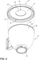
FIG. 4 is a bottom perspective assembly view of the dust cover and the mixing bowl; and -
FIG. 5 is a cross-section view of the dust cover in a further use condition in connection with an assembly of nested mixing bowls. - The components in the figures are not necessarily to scale, emphasis instead being placed upon illustrating the principles described herein.
- The present illustrated embodiments reside primarily in combinations of apparatus components related to a stand mixer appliance. Accordingly, the apparatus components have been represented, where appropriate, by conventional symbols in the drawings, showing only those specific details that are pertinent to understanding the embodiments of the present disclosure so as not to obscure the disclosure with details that will be readily apparent to those of ordinary skill in the art having the benefit of the description herein. Further, like numerals in the description and drawings represent like elements.
- For purposes of description herein, the terms "upper," "lower," "right," "left," "rear," "front," "vertical," "horizontal," and derivatives thereof shall relate to the disclosure as oriented in
FIG. 1 . Unless stated otherwise, the term "front" shall refertothe surface of the element closer to an intended viewer, and the term "rear" shall refer to the surface of the element further from the intended viewer. However, it is to be understood that the disclosure may assume various alternative orientations, except where expressly specified to the contrary. It is also to be understood that the specific devices and processes illustrated in the attached drawings, and described in the following specification are simply exemplary embodiments of the inventive concepts defined in the appended claims. Hence, specific dimensions and other physical characteristics relating to the embodiments disclosed herein are not to be considered as limiting, unless the claims expressly state otherwise. - The terms "including," "comprises," "comprising," or any other variation thereof, are intended to cover a non-exclusive inclusion, such that an article or apparatus that comprises a list of elements does not include only those elements but may include other elements not expressly listed or inherent to such process, method, article, or apparatus. An element preceded by "comprises a . . . " does not, without more constraints, preclude the existence of additional identical elements in the process, method, article, or apparatus that comprises the element.
- Referring to
FIGS. 1-5 ,reference numeral 10 generally designates a dust cover for astand mixer bowl 12. Thedust cover 10 includes a disc-shaped body 14 defining acentral aperture 16 therethrough and extending from thecentral aperture 16 to anouter extent 18 and arim 20 extending from theouter extent 18 of the disc-shaped body 14 to define aninterior portion 22 of thedust cover 10 with the disc-shaped body 14. Theinterior portion 22 of thedust cover 10 is configured to removably receive anupper portion 24 of themixing bowl 12 with the disc-shaped body 14 extending inwardly from alip 26 of themixing bowl 12 positioned adjacent theouter extent 18 of the disc-shaped body 14 over at least a portion of aninterior 28 of themixing bowl 12. Thecentral aperture 16 is configured for a portion of aplanetary hub 30 of astand mixer 32 to extend therethrough with anouter surface 34 of the portion of theplanetary hub 30 adjacent aninner edge 36 of thecentral aperture 16 when thedust cover 10 receives theupper portion 24 of themixing bowl 12 when themixing bowl 12 is coupled to thestand mixer 32 in a storage position thereof. - As particularly shown in
FIGS. 2 and3 , thecentral aperture 16 of thedust cover 10 is present and configured to allow thedust cover 10 to be used in connection with themixing bowl 12 when in place on thestand mixer 32. In the illustrated example, themixing bowl 12 is configured such that thelip 26 thereof is positioned in horizontal alignment with a portion of theplanetary hub 30 of thestand mixer 32. As can be appreciated, theplanetary hub 30 includes ahub body 38 and anoutput shaft 40 and is configured such that thehub body 38 rotates along an orbital path that generally corresponds with the shape of thehub body 38. Theoutput shaft 40 moves along the orbital path of thehub body 38 while itself rotating (including, in one implementation, in an opposite direction) in a planetary motion due to its offset position within thehub body 38. In this manner, depending on the height of themixing bowl 12 and the particular configuration of thebody 14 of thedust cover 10, theplanetary hub 30 can be received through theaperture 16, to varying degrees, to allow thestand mixer 32 to be stored, for example, with amixing head 42 of thestand mixer 32 in the lowered position (to further save space, as thestand mixer 32 is generally more compact with themixing head 42 lowered, as opposed to raised). In this manner, theinner edge 36 of theaperture 16 may horizontally align, in particular, with theoutput shaft 40 or thehub body 38. In either configuration, theaperture 16 is sized to allow theoutput shaft 40 to wholly or partially extend therethrough and into theinterior 28 of themixing bowl 12. - Because the position of the
output shaft 40 moves with the orbital rotation of thehub body 38, theaperture 16 can be sized to allow theoutput shaft 40 to pass therethrough throughout the range of motion thereof with additional clearance to allow for tolerance stack-up and ease of operation. In one respect, the clearance provided (i.e., the distance between theinner edge 36 of theaperture 16 and the adjacentoutermost portion 34 of theplanetary hub 30, which may be defined on theoutput shaft 40, as shown, or on the hub body 38) can allow for location and or movement of anyattachment structure 44 positioned on theoutput shaft 40. In a further aspect, theaperture 16 can be sized to accommodate thehub body 38 therein, which may have a widest point along acollar 46 from which theoutput shaft 40 extends. Again, as the positon of thecollar 46 may vary when thestand mixer 32 is powered off for storage, theaperture 16 can be sized to allow clearance for the collar46. In one implementation, theaperture 16 can have a radius that is at least 3 mm greater than the distance from the outermost position along thecollar 46 to a rotational center of theplanetary hub 30. As shown, thebody 14 of thedust cover 10 can be somewhat concave such that there is vertical clearance between themixing head 42 and thedust cover 10, particularly when used with taller implementations of themixing bowl 12, as shown inFIGS. 1-3 . - As discussed, the
central aperture 16 can be sized to correspond with an outer path of the outermostadjacent surface portion 34 of theplanetary output hub 30 through an operational range of motion thereof. In this respect, therelevant portion 34 of theplanetary hub 30 can vary between thehub body 38 and theoutput shaft 40 and may, further vary in the case of theoutput hub 30 as theoutput hub 30 rotates about its axis, assuch portion 34 is, in at least one aspect, determined by its closest proximity to theinner edge 36 of thecentral aperture 16. In one aspect, the fit between theplanetary hub 30 and theaperture 16, while being configured for reliable and convenient for use during storage of themixing bowl 12 on thestand mixer 32, can be unsuited for use as a "splash guard" during use of themixing bowl 12 with thestand mixer 32. In this respect, the fit between thecentral aperture 16 and therelevant portion 34 of theplanetary hub 30 can be close enough that thecentral aperture 16 is within an operational tolerance of the outer path of thesurface 34 of theplanetary hub 30 within at least a portion of the operational range of motion thereof. In this respect, the rotation of thehub body 38 and theoutput shaft 40 under load, while mixing ingredients and/or food product(s) may cause the position of thesurface 34 to vary by more than the operational path alone. This additional variance can be anticipated with respect to ordinary operation of thestand mixer 32, including with a designated splash guard, but the distance between thesurface portion 34 of theplanetary hub 30 and theinner edge 36 of thecentral aperture 16 may be within such anticipated variation, such that interference may result if thedust cover 10 is left in place on themixing bowl 12 during use of the same with thestand mixer 32. In another aspect, thecentral aperture 16 may be positioned beneath themixing head 42, such that the introduction of ingredients through thecentral aperture 16 is impeded. In one implementation, theouter surface 34 of theplanetary output hub 30 can be within about 3 mm of theinner edge 36 of thecentral aperture 16 when thedust cover 10 is in place on themixing bowl 12 and themixing bowl 12 is mounted with thestand mixer 32. In a further aspect, Thecentral aperture 16 can have a radius of 40 mm or about 40 mm (e.g., +/-5%). - As further shown in
FIG. 2 , themixing bowl 12 includes a base 48 configured for mounting with abowl coupling 50 of thestand mixer 32. In one implementation, thebowl coupling 50 can be a twist-fit (also referred to as a bayonet-style) fitting, where thebase 48 is positioned within thebowl coupling 50 and turned (e.g. one-quarter turn clockwise or anti-clockwise) to secure themixing bowl 12 in place. In other implementations, thepresent dust cover 10 can be interchangeably used with a bowl-lift type mixer and the related compatible mixing bowl. As shown, thebody 14 of themixing bowl 12 extends upward from the base 48 to theupper portion 24 thereof, where thelip 26 is located. In this manner, thedust cover 10 can be useable in an assembly with the depictedmixing bowl 12 and in a further assembly with themixing bowl 12 and thestand mixer 32 in a storage position of the assembled mixingbowl 12 and standmixer 32. Thedust cover 10 is, accordingly, removable from themixing bowl 12 for use of thestand mixer 32 in connection with themixing bowl 12. In one example, this can be accomplished without removing themixing bowl 12 from thestand mixer 32 by tilting the mixinghead 42 upward such that theplanetary hub 30 is removed from thecentral aperture 16, at which point thedust cover 10 can be lifted off of theupper portion 24 of themixing bowl 12 and stored on its own or in connection with any other mixing bowls or items stored within the utilizedmixing bowl 12. Other use cases may be realized by the utilization of different mixing bowls and different storage combinations thereof. - As particularly shown in
FIG. 4 , therim 20 can extend away from thebody 14 of thedust cover 10 by a distance greater than the height of thelip 26 of acompatible mixing bowl 12. In one aspect, this can generally facilitate resting of thedust cover 10 on themixing bowl 12 with reliable enough positioning to allow movement of the assembleddust cover 10, mixingbowl 12 and standmixer 32, while allowing thedust cover 10 to be useable withmixing bowls 12 with varyinglip 26 height or other configurations. In a particular aspect, shown inFIG. 5 , the previously-describedmixing bowl 12 can be afirst mixing bowl 12a and thelip 26 andinterior cavity 28 can be, respectively, afirst lip 26a and a firstinterior cavity 28a of thefirst mixing bowl 12a. In this respect, an implementation of the above-described assemblies can further include asecond mixing bowl 12b having a second body 14b extending to asecond lip 26b to define a secondinterior cavity 28b with the second body 14b of thesecond mixing bowl 12b being received within thefirst mixing bowl 12a with the second rim 20b in supporting contact with the first rim 20a of thefirst mixing bowl 12a. In this arrangement, respectiveupper portions second mixing bowls interior portion 22 of thedust cover 10. Therim 20 of thedust cover 10 can extend away from thebody 14 to a first distance D that is greater than a height of theupper lip 26a of themixing bowl 12b such that a portion of therim 20 can engage with thefirst lip 26a of thefirst mixing bowl 12a over thesecond lip 26b of thesecond mixing bowl 12b. - As further shown the
rim 20 can further accommodate athird mixing bowl 12c similarly positioned within the interior 28b of thesecond mixing bowl 12b with thelip 26c of thethird mixing bowl 12c resting on thelip 26b of thesecond mixing bowl 12b. For compatibility with this arrangement ofmixing bowls rim 20 can extend away from thebody 14 of thedust cover 10 such that the first distance H is at least three times greater than a height of anupper lip 26a of themixing bowl 12a such that a portion of therim 20, including adetent feature 52 thereof, can engage with thelip 26a of thelowermost mixing bowl 12a when the twoadditional mixing bowls outermost mixing bowl 12a with therespective lips lip 26a of themixing bowl 12a. In one aspect, theinner surface 54 of therim 20 can have a radius R that provides a loose, sliding fit with themixing bowl 12a. In other aspects, thedetent feature 52 can extend around all or a portion of theinner surface 54 of therim 20 to facilitate a snap-fit engagement with themixing bowl 12a, which may help to retain the assembly of themixing bowl 12a and the depictedadditional mixing bowls sized mixing bowl 12a (e.g., having a radius of between about 113 mm and 114.5 mm). - The invention disclosed herein is further summarized in the following paragraphs and is further characterized by combinations of any and all of the various aspects described therein.
- According to another aspect of the present disclosure, a dust cover for a stand mixer bowl includes a disc-shaped body defining a central aperture therethrough and extending from the central aperture to an outer extent and a rim extending from the outer extent of the disc-shaped body to define an interior portion of the dust cover with the disc-shaped body. The interior portion of the dust cover is configured to removably receive an upper portion of a mixing bowl with the disc-shaped body extending inwardly from a lip of the mixing bowl positioned adjacent the outer extent of the disc-shaped body over at least a portion of an interior of the mixing bowl. The central aperture is configured for a portion of a planetary hub of a stand mixer to extend therethrough with an outer surface of the portion of the planetary hub adjacent an inner edge of the central aperture when the dust cover receives the upper portion of the mixing bowl when the mixing bowl is coupled to the stand mixer in a storage position thereof.The central aperture can be sized to correspond with an outer path of the surface of the planetary output hub through an operational range of motion thereof.
- The central aperture can be sized to be within an operational tolerance of the outer path of the surface of the planetary output hub within at least a portion of the operational range of motion thereof.
- The outer surface of the planetary output shaft can be within about 3 mm of an inner edge of the central aperture when the dust cover receives the upper portion of the mixing bowl.
- The central aperture can have a radius of 40 mm.
- An inner surface of the rim can have a radius of 115 mm.
- The rim can extend away from the disc-shaped body to a first distance that is at least three times greater than a height of an upper lip of the mixing bowl such that a portion of the rim can engage with the lip of the mixing bowl when a first and a second additional mixing bowl are nested within the mixing bowl with respective lips thereof in a stacked arrangement with the lip of the mixing bowl.
- According to yet another aspect, a mixing bowl assembly for use with a stand mixer includes a mixing bowl having a body extending to a lip and defining an interior cavity and a dust cover having a disc-shaped body defining a central aperture therethrough and extending from the central aperture to an outer extent and a rim extending from the outer extent of the disc-shaped body to define an interior portion of the dust cover with the disc-shaped body. An upper portion of the mixing bowl is received within the interior portion of the dust cover, with the disc-shaped body extending inwardly from the lip of the mixing bowl positioned adjacent the outer extent of the disc-shaped body, over at least a portion of an interior of the mixing bowl. The central aperture is configured for a portion of a planetary hub of a stand mixer to extend therethrough into the interior cavity of the mixing bowl with an outer surface of the portion of the planetary hub adjacent an inner edge of the central aperture when the dust cover receives the upper portion of the mixing bowl and the mixing bowl is coupled to the stand mixer in a storage position thereof.
- The mixing bowl can include a base configured for mounting with a bowl coupling of the stand mixer, the body of the mixing bowl extending from the base.
- The dust cover can be removable from the mixing bowl for use of the stand mixer in connection with the mixing bowl.
- The mixing bowl can be a first mixing bowl and the lip and interior cavity can be, respectively, first and second interior cavities of the first mixing bowl, and the assembly can further include a second mixing bowl having a second body extending to a second lip to define a second interior cavity, the second body of the second mixing bowl being received within the first mixing bowl with the second rim in supporting contact with the first rim of the first mixing bowl.
- Upper portions of both the first and second mixing bowls can be received within the interior portion of the dust cover.
- The rim of the dust cover can extend away from the disc-shaped body to a first distance that is greater than a height of an upper lip of the mixing bowl such that a portion of the rim can engage with the first lip of the first mixing bowl over the second lip of the second mixing bowl.
- The central aperture of the dust cover can be sized to correspond with an outer path of the surface of the planetary output hub through an operational range of motion thereof.
- The central aperture can be sized to be within an operational tolerance of the outer path of the surface of the planetary output hub within at least a portion of the operational range of motion thereof.
- The outer surface of the planetary output shaft can be within about 3 mm of an inner edge of the central aperture when the mixing bowl is coupled with the base of the stand mixer.
- The central aperture can have a radius of 40 mm.
- An inner surface of the rim can have a radius of 115 mm.
- According to yet another aspect, a stand mixer includes a base having a bowl coupler, a mixing head coupled with the base and having an output hub extending therefrom, a mixing bowl having a base removably coupled with the bowl coupler and a body extending from the base to a lip and defining an interior cavity, and a dust cover. The dust cover has a disc-shaped body defining a central aperture therethrough and extending from the central aperture to an outer extent and a rim extending from the outer extent of the disc-shaped body to define an interior portion of the dust cover with the disc-shaped body. An upper portion of the mixing bowl is received within the interior portion of the dust cover, with the disc-shaped body extending inwardly from the lip of the mixing bowl positioned adjacent the outer extent of the disc-shaped body, over at least a portion of an interior of the mixing bowl. The central aperture is configured for a portion of the planetary hub to extend therethrough into the interior cavity of the mixing bowl with an outer surface of the portion of the planetary hub adjacent an inner edge of the central aperture.
- The mixing bowl can be a first mixing bowl and the lip and interior cavity can be, respectively, first and second interior cavities of the first mixing bowl, and the stand mixer can further include a second mixing bowl having a second body extending to a second lip to define a second interior cavity, the second body of the second mixing bowl being received within the first mixing bowl with the second rim in supporting contact with the first rim of the first mixing bowl.
Claims (15)
- A dust cover (10) for a stand mixer bowl (12), comprising:a disc-shaped body (14) defining a central aperture (16) therethrough and extending from the central aperture (16) to an outer extent (18); anda rim (20) extending from the outer extent (18) of the disc-shaped body (14) to define an interior portion (22) of the dust cover (10) with the disc-shaped body (14);wherein:the interior portion (22) of the dust cover (10) is configured to removably receive an upper portion (24) of the mixing bowl (12) with the disc-shaped body (14) extending inwardly from a lip (26) of the mixing bowl (12) positioned adjacent the outer extent (18) of the disc-shaped body (14) over at least a portion of an interior (28) of the mixing bowl (12); andthe central aperture (16) is configured for a portion of the planetary hub (30) of the stand mixer (32) to extend therethrough with an outer surface (34) of the portion of the planetary hub (30) adjacent an inner edge (36) of the central aperture (16) when the dust cover (10) receives the upper portion (24) of the mixing bowl (12) when the mixing bowl (12) is coupled to the stand mixer (32) in a storage position thereof.
- The dust cover (10) for a stand mixer bowl (12) of claim 1, wherein the central aperture (16) is sized to correspond with an outer path of the surface of the planetary output hub (30) through an operational range of motion thereof.
- The dust cover (10) for a stand mixer bowl (12) of claim 2, wherein the central aperture (16) is sized to be within an operational tolerance of the outer path of the surface of the planetary output hub (30) within at least a portion of the operational range of motion thereof.
- The dust cover (10) for a stand mixer bowl (12) of any of the preceding claims, wherein the outer surface of a planetary output shaft (40) is within about 3 mm of the inner edge (36) of the central aperture (16) when the dust cover (10) receives the upper portion (24) of the mixing bowl (12).
- The dust cover (10) for a stand mixer bowl (12) of any of the preceding claims, wherein the central aperture (16) has a radius of about 40 mm.
- The dust cover (10) for a stand mixer bowl (12) of any of the preceding claims, wherein an inner surface (54) of the rim (20) has a radius of about 115 mm.
- The dust cover (10) for a stand mixer bowl (12) of any of the preceding claims, wherein the rim (20) extends away from the disc-shaped body (14) to a first distance (H) that is at least three times greater than a height of an upper lip (26a) of the mixing bowl (12a) such that a portion of the rim (20) can engage with the lip (26a) of the mixing bowl (12a) when a first and a second additional mixing bowl (12b, 12c) are nested within the mixing bowl (12a) with respective lips (26b, 26c) thereof in a stacked arrangement with the lip (26a) of the mixing bowl (12a).
- A stand mixer (32), comprising:a base having a bowl coupling (50);a mixing head (42) coupled with the base of the stand mixer (32) and having a planetary hub (30) extending therefrom;a mixing bowl (12) including a body (14) extending to a lip (26) and defining an interior cavity (28); andthe dust cover (10) of any of claims 1-7.
- The stand mixer (32) of claim 8, wherein the mixing bowl (12) includes a base (48) configured for mounting with the bowl coupling (50) of the stand mixer (32), the body (14) of the mixing bowl (12) extending from the base (48).
- The stand mixer (32) of claim 8 or 9, wherein the dust cover (10) is removable from the mixing bowl (12) for use of the stand mixer (32) in connection with the mixing bowl (12).
- The stand mixer (32) of any one of claims 8-10, wherein the mixing bowl (12) is a first mixing bowl (12a) and the lip (26) and the interior cavity (28) are, respectively, a first lip (26a) and a first interior cavity (28a) of the first mixing bowl (12a), the assembly further including:
a second mixing bowl (12b) including a second body (14b) extending to a second lip (26b) to define a second interior cavity (28b), the second body (14b) of the second mixing bowl (12b) being received within the first mixing bowl (12a) with a second rim (12b) in supporting contact with the first lip (26a) of the first mixing bowl (12a). - The stand mixer (32) of claim 11, wherein the upper portion (24a) of the first mixing bowl (12a) and an upper portion (24b) of the second mixing bowl (12b) are received within the interior portion (22) of the dust cover (10).
- The stand mixer (32) of claim 12, wherein the rim (20) of the dust cover (10) extends away from the disc-shaped body (14) to a first distance (H) that is greater than a height of an upper lip (26a) of the mixing bowl (12a) such that a portion of the rim (20) can engage with the first lip (26a) of the first mixing bowl (12a) over the second lip (26b) of the second mixing bowl (12b).
- The stand mixer (32) of any one of claims 8 to 13, wherein the central aperture (16) of the dust cover (10) is sized to correspond with an outer path of the surface (34) of the planetary output hub (30) through an operational range of motion thereof.
- The stand mixer (32) of claim 14, wherein the central aperture (16) is sized to be within an operational tolerance of the outer path of the surface (34) of the planetary output hub (30) within at least a portion of the operational range of motion thereof.
Applications Claiming Priority (1)
| Application Number | Priority Date | Filing Date | Title |
|---|---|---|---|
| US17/585,851 US12403435B2 (en) | 2022-01-27 | 2022-01-27 | Storage dust cover for a stand mixer bowl |
Publications (1)
| Publication Number | Publication Date |
|---|---|
| EP4218994A1 true EP4218994A1 (en) | 2023-08-02 |
Family
ID=85076494
Family Applications (1)
| Application Number | Title | Priority Date | Filing Date |
|---|---|---|---|
| EP23152972.8A Pending EP4218994A1 (en) | 2022-01-27 | 2023-01-23 | Storage dust cover for a stand mixer bowl |
Country Status (2)
| Country | Link |
|---|---|
| US (1) | US12403435B2 (en) |
| EP (1) | EP4218994A1 (en) |
Cited By (1)
| Publication number | Priority date | Publication date | Assignee | Title |
|---|---|---|---|---|
| EP4218514A1 (en) * | 2022-01-28 | 2023-08-02 | Whirlpool Corporation | Set of stand mixer bowls and related assemblies |
Families Citing this family (1)
| Publication number | Priority date | Publication date | Assignee | Title |
|---|---|---|---|---|
| USD1063505S1 (en) * | 2022-10-25 | 2025-02-25 | Whirlpool Corporation | Stand mixer |
Citations (3)
| Publication number | Priority date | Publication date | Assignee | Title |
|---|---|---|---|---|
| US2802499A (en) * | 1954-11-17 | 1957-08-13 | Earl S Tupper | Adapter cover |
| GR1006382B (en) * | 2008-01-24 | 2009-05-07 | Χαραλαμπος Χρηστου Μπριολας | Seal for mixer-equipped liquid-containing vials |
| US20120170404A1 (en) * | 2010-12-29 | 2012-07-05 | Whirlpool Corporation | Mixing bowl liner and lid |
Family Cites Families (7)
| Publication number | Priority date | Publication date | Assignee | Title |
|---|---|---|---|---|
| US2504727A (en) | 1949-11-07 | 1950-04-18 | Frank B Post | Mixer bowl cover |
| US2858118A (en) | 1956-12-14 | 1958-10-28 | Estelle M Perkins | Mixing bowl cover |
| US3913896A (en) | 1973-06-22 | 1975-10-21 | Ethel M Hawke | Splatter shield for mixing bowls and the like |
| US5660469A (en) | 1996-08-01 | 1997-08-26 | Seguin; Ronald John | Cover unit for an industrial food mixer |
| US6435708B1 (en) | 2002-02-12 | 2002-08-20 | Spar Food Machinery Co., Ltd. | Safety protective cover of a blender |
| GB2459309A (en) | 2008-04-19 | 2009-10-21 | Kenwood Ltd | A Stand Mixer with guarding device |
| GB2519368A (en) | 2013-10-21 | 2015-04-22 | Kenwood Ltd | Kitchen machine with splash guard |
-
2022
- 2022-01-27 US US17/585,851 patent/US12403435B2/en active Active
-
2023
- 2023-01-23 EP EP23152972.8A patent/EP4218994A1/en active Pending
Patent Citations (3)
| Publication number | Priority date | Publication date | Assignee | Title |
|---|---|---|---|---|
| US2802499A (en) * | 1954-11-17 | 1957-08-13 | Earl S Tupper | Adapter cover |
| GR1006382B (en) * | 2008-01-24 | 2009-05-07 | Χαραλαμπος Χρηστου Μπριολας | Seal for mixer-equipped liquid-containing vials |
| US20120170404A1 (en) * | 2010-12-29 | 2012-07-05 | Whirlpool Corporation | Mixing bowl liner and lid |
Cited By (1)
| Publication number | Priority date | Publication date | Assignee | Title |
|---|---|---|---|---|
| EP4218514A1 (en) * | 2022-01-28 | 2023-08-02 | Whirlpool Corporation | Set of stand mixer bowls and related assemblies |
Also Published As
| Publication number | Publication date |
|---|---|
| US12403435B2 (en) | 2025-09-02 |
| US20230264157A1 (en) | 2023-08-24 |
Similar Documents
| Publication | Publication Date | Title |
|---|---|---|
| US12006105B2 (en) | Lid for container | |
| US12403435B2 (en) | Storage dust cover for a stand mixer bowl | |
| US4212415A (en) | Housing and module therefor | |
| US9925506B2 (en) | Pouring shield for a stand mixer | |
| US6616324B1 (en) | Food processing appliance with storable tool support | |
| WO2011001284A1 (en) | A container for snus | |
| EP4218514A1 (en) | Set of stand mixer bowls and related assemblies | |
| JP2025016359A (en) | Cosmetic Packaging Box | |
| US11161665B2 (en) | Child resistant dial pack | |
| JP5948868B2 (en) | mixer | |
| JP6767178B2 (en) | Vacuum cleaner with improved latch | |
| CN219289293U (en) | Charging assembly and cooking machine | |
| JP2001225902A (en) | Refuse bin cover | |
| CN212117911U (en) | Side dish pouring device and cooking machine | |
| JP3055403B2 (en) | Box-shaped cup holder | |
| CN210654367U (en) | Food holding device | |
| CN221105517U (en) | Pressure cooking utensil | |
| CN223731270U (en) | Novel stirrer | |
| JP2000016138A (en) | Cup holder device | |
| CN107788830B (en) | Cooking pot | |
| CN218840368U (en) | Storage tank | |
| JP4616019B2 (en) | Cake packaging containers | |
| JP2001047012A (en) | Garbage disposal equipment | |
| CN222134933U (en) | Modular tool container | |
| CN222584197U (en) | Magnetic suction type bracket cup cover |
Legal Events
| Date | Code | Title | Description |
|---|---|---|---|
| PUAI | Public reference made under article 153(3) epc to a published international application that has entered the european phase |
Free format text: ORIGINAL CODE: 0009012 |
|
| STAA | Information on the status of an ep patent application or granted ep patent |
Free format text: STATUS: THE APPLICATION HAS BEEN PUBLISHED |
|
| AK | Designated contracting states |
Kind code of ref document: A1 Designated state(s): AL AT BE BG CH CY CZ DE DK EE ES FI FR GB GR HR HU IE IS IT LI LT LU LV MC ME MK MT NL NO PL PT RO RS SE SI SK SM TR |
|
| STAA | Information on the status of an ep patent application or granted ep patent |
Free format text: STATUS: REQUEST FOR EXAMINATION WAS MADE |
|
| 17P | Request for examination filed |
Effective date: 20240125 |
|
| RBV | Designated contracting states (corrected) |
Designated state(s): AL AT BE BG CH CY CZ DE DK EE ES FI FR GB GR HR HU IE IS IT LI LT LU LV MC ME MK MT NL NO PL PT RO RS SE SI SK SM TR |
|
| STAA | Information on the status of an ep patent application or granted ep patent |
Free format text: STATUS: EXAMINATION IS IN PROGRESS |
|
| 17Q | First examination report despatched |
Effective date: 20241203 |