EP4218989A1 - Unit for direct capture of carbon dioxide - Google Patents
Unit for direct capture of carbon dioxide Download PDFInfo
- Publication number
- EP4218989A1 EP4218989A1 EP22153483.7A EP22153483A EP4218989A1 EP 4218989 A1 EP4218989 A1 EP 4218989A1 EP 22153483 A EP22153483 A EP 22153483A EP 4218989 A1 EP4218989 A1 EP 4218989A1
- Authority
- EP
- European Patent Office
- Prior art keywords
- lid
- adsorption
- adsorption cell
- opening
- cell
- Prior art date
- Legal status (The legal status is an assumption and is not a legal conclusion. Google has not performed a legal analysis and makes no representation as to the accuracy of the status listed.)
- Pending
Links
- CURLTUGMZLYLDI-UHFFFAOYSA-N Carbon dioxide Chemical compound O=C=O CURLTUGMZLYLDI-UHFFFAOYSA-N 0.000 title claims abstract description 80
- 229910002092 carbon dioxide Inorganic materials 0.000 title claims abstract description 40
- 239000001569 carbon dioxide Substances 0.000 title claims abstract description 40
- 238000001179 sorption measurement Methods 0.000 claims abstract description 173
- 239000002594 sorbent Substances 0.000 claims description 46
- 238000003795 desorption Methods 0.000 claims description 22
- 238000000034 method Methods 0.000 claims description 17
- 239000007787 solid Substances 0.000 claims description 14
- 238000007789 sealing Methods 0.000 claims description 4
- 238000010521 absorption reaction Methods 0.000 claims description 3
- 150000001412 amines Chemical class 0.000 claims description 3
- 230000008878 coupling Effects 0.000 claims 1
- 238000010168 coupling process Methods 0.000 claims 1
- 238000005859 coupling reaction Methods 0.000 claims 1
- 239000003570 air Substances 0.000 description 59
- XLYOFNOQVPJJNP-UHFFFAOYSA-N water Substances O XLYOFNOQVPJJNP-UHFFFAOYSA-N 0.000 description 3
- 238000001816 cooling Methods 0.000 description 2
- 238000001035 drying Methods 0.000 description 2
- 230000013011 mating Effects 0.000 description 2
- 238000010926 purge Methods 0.000 description 2
- 241001465754 Metazoa Species 0.000 description 1
- 229910000831 Steel Inorganic materials 0.000 description 1
- 239000012080 ambient air Substances 0.000 description 1
- 125000003277 amino group Chemical group 0.000 description 1
- 230000015556 catabolic process Effects 0.000 description 1
- 238000006243 chemical reaction Methods 0.000 description 1
- 238000009833 condensation Methods 0.000 description 1
- 230000005494 condensation Effects 0.000 description 1
- 238000010276 construction Methods 0.000 description 1
- 230000007123 defense Effects 0.000 description 1
- 238000006731 degradation reaction Methods 0.000 description 1
- 230000005611 electricity Effects 0.000 description 1
- 239000008187 granular material Substances 0.000 description 1
- 238000010438 heat treatment Methods 0.000 description 1
- 230000000977 initiatory effect Effects 0.000 description 1
- 238000007689 inspection Methods 0.000 description 1
- 239000002808 molecular sieve Substances 0.000 description 1
- 229920000642 polymer Polymers 0.000 description 1
- URGAHOPLAPQHLN-UHFFFAOYSA-N sodium aluminosilicate Chemical compound [Na+].[Al+3].[O-][Si]([O-])=O.[O-][Si]([O-])=O URGAHOPLAPQHLN-UHFFFAOYSA-N 0.000 description 1
- 239000010959 steel Substances 0.000 description 1
Images



Classifications
-
- B—PERFORMING OPERATIONS; TRANSPORTING
- B01—PHYSICAL OR CHEMICAL PROCESSES OR APPARATUS IN GENERAL
- B01D—SEPARATION
- B01D53/00—Separation of gases or vapours; Recovering vapours of volatile solvents from gases; Chemical or biological purification of waste gases, e.g. engine exhaust gases, smoke, fumes, flue gases, aerosols
- B01D53/02—Separation of gases or vapours; Recovering vapours of volatile solvents from gases; Chemical or biological purification of waste gases, e.g. engine exhaust gases, smoke, fumes, flue gases, aerosols by adsorption, e.g. preparative gas chromatography
- B01D53/04—Separation of gases or vapours; Recovering vapours of volatile solvents from gases; Chemical or biological purification of waste gases, e.g. engine exhaust gases, smoke, fumes, flue gases, aerosols by adsorption, e.g. preparative gas chromatography with stationary adsorbents
- B01D53/0407—Constructional details of adsorbing systems
- B01D53/0423—Beds in columns
-
- B—PERFORMING OPERATIONS; TRANSPORTING
- B01—PHYSICAL OR CHEMICAL PROCESSES OR APPARATUS IN GENERAL
- B01D—SEPARATION
- B01D53/00—Separation of gases or vapours; Recovering vapours of volatile solvents from gases; Chemical or biological purification of waste gases, e.g. engine exhaust gases, smoke, fumes, flue gases, aerosols
- B01D53/34—Chemical or biological purification of waste gases
- B01D53/46—Removing components of defined structure
- B01D53/62—Carbon oxides
-
- B—PERFORMING OPERATIONS; TRANSPORTING
- B01—PHYSICAL OR CHEMICAL PROCESSES OR APPARATUS IN GENERAL
- B01D—SEPARATION
- B01D53/00—Separation of gases or vapours; Recovering vapours of volatile solvents from gases; Chemical or biological purification of waste gases, e.g. engine exhaust gases, smoke, fumes, flue gases, aerosols
- B01D53/02—Separation of gases or vapours; Recovering vapours of volatile solvents from gases; Chemical or biological purification of waste gases, e.g. engine exhaust gases, smoke, fumes, flue gases, aerosols by adsorption, e.g. preparative gas chromatography
- B01D53/04—Separation of gases or vapours; Recovering vapours of volatile solvents from gases; Chemical or biological purification of waste gases, e.g. engine exhaust gases, smoke, fumes, flue gases, aerosols by adsorption, e.g. preparative gas chromatography with stationary adsorbents
- B01D53/0407—Constructional details of adsorbing systems
- B01D53/0446—Means for feeding or distributing gases
-
- B—PERFORMING OPERATIONS; TRANSPORTING
- B01—PHYSICAL OR CHEMICAL PROCESSES OR APPARATUS IN GENERAL
- B01D—SEPARATION
- B01D53/00—Separation of gases or vapours; Recovering vapours of volatile solvents from gases; Chemical or biological purification of waste gases, e.g. engine exhaust gases, smoke, fumes, flue gases, aerosols
- B01D53/34—Chemical or biological purification of waste gases
- B01D53/74—General processes for purification of waste gases; Apparatus or devices specially adapted therefor
- B01D53/81—Solid phase processes
- B01D53/82—Solid phase processes with stationary reactants
-
- B—PERFORMING OPERATIONS; TRANSPORTING
- B01—PHYSICAL OR CHEMICAL PROCESSES OR APPARATUS IN GENERAL
- B01D—SEPARATION
- B01D53/00—Separation of gases or vapours; Recovering vapours of volatile solvents from gases; Chemical or biological purification of waste gases, e.g. engine exhaust gases, smoke, fumes, flue gases, aerosols
- B01D53/34—Chemical or biological purification of waste gases
- B01D53/96—Regeneration, reactivation or recycling of reactants
-
- B—PERFORMING OPERATIONS; TRANSPORTING
- B01—PHYSICAL OR CHEMICAL PROCESSES OR APPARATUS IN GENERAL
- B01D—SEPARATION
- B01D2253/00—Adsorbents used in seperation treatment of gases and vapours
- B01D2253/20—Organic adsorbents
- B01D2253/202—Polymeric adsorbents
-
- B—PERFORMING OPERATIONS; TRANSPORTING
- B01—PHYSICAL OR CHEMICAL PROCESSES OR APPARATUS IN GENERAL
- B01D—SEPARATION
- B01D2253/00—Adsorbents used in seperation treatment of gases and vapours
- B01D2253/25—Coated, impregnated or composite adsorbents
-
- B—PERFORMING OPERATIONS; TRANSPORTING
- B01—PHYSICAL OR CHEMICAL PROCESSES OR APPARATUS IN GENERAL
- B01D—SEPARATION
- B01D2257/00—Components to be removed
- B01D2257/50—Carbon oxides
- B01D2257/504—Carbon dioxide
-
- B—PERFORMING OPERATIONS; TRANSPORTING
- B01—PHYSICAL OR CHEMICAL PROCESSES OR APPARATUS IN GENERAL
- B01D—SEPARATION
- B01D2258/00—Sources of waste gases
- B01D2258/06—Polluted air
-
- B—PERFORMING OPERATIONS; TRANSPORTING
- B01—PHYSICAL OR CHEMICAL PROCESSES OR APPARATUS IN GENERAL
- B01D—SEPARATION
- B01D2259/00—Type of treatment
- B01D2259/40—Further details for adsorption processes and devices
- B01D2259/40083—Regeneration of adsorbents in processes other than pressure or temperature swing adsorption
- B01D2259/40088—Regeneration of adsorbents in processes other than pressure or temperature swing adsorption by heating
- B01D2259/4009—Regeneration of adsorbents in processes other than pressure or temperature swing adsorption by heating using hot gas
-
- Y—GENERAL TAGGING OF NEW TECHNOLOGICAL DEVELOPMENTS; GENERAL TAGGING OF CROSS-SECTIONAL TECHNOLOGIES SPANNING OVER SEVERAL SECTIONS OF THE IPC; TECHNICAL SUBJECTS COVERED BY FORMER USPC CROSS-REFERENCE ART COLLECTIONS [XRACs] AND DIGESTS
- Y02—TECHNOLOGIES OR APPLICATIONS FOR MITIGATION OR ADAPTATION AGAINST CLIMATE CHANGE
- Y02C—CAPTURE, STORAGE, SEQUESTRATION OR DISPOSAL OF GREENHOUSE GASES [GHG]
- Y02C20/00—Capture or disposal of greenhouse gases
- Y02C20/40—Capture or disposal of greenhouse gases of CO2
Definitions
- Direct air capture is a process of capturing carbon dioxide (CO2) directly from an air stream.
- CO2 carbon dioxide
- One method of direct air capture uses a sorbent to capture and remove the CO2 from the air stream upon contact.
- the disadvantages of this method of direct air capture include the high cost of the equipment, the high heat demand for the desorption and its high electricity demand.
- a carbon dioxide capture unit includes a frame arranged to define a first adsorption unit and a second adsorption unit arranged around a central axis, a first adsorption cell disposed in the first adsorption unit and a second adsorption cell disposed in the second adsorption unit, the first adsorption cell and the second adsorption cell each including a first opening and a second opening, a hub rotatably coupled to the frame for rotation around the central axis, an upper arm coupled to the hub for co-rotation around the central axis, a lower arm coupled to the hub for co-rotation around the central axis, and an upper lid coupled to the upper arm and movable between an open position and a closed position.
- the upper arm and the lower arm are movable so that the upper and lower lid are positioned concentric with the first opening and the second opening, respectively, and movable to the closed position in response to operation in a desorption
- a system of direct air capture of carbon dioxide includes a fixed structure including an opening and a fan positioned in the opening operable to draw air into an inlet of the adsorption cell through sorbent material and out an outlet of the adsorption cell during an adsorption phase of the direct air capture so that the air flows through a wave pattern of the sorbent material.
- the fixed structure includes an adsorption cell positioned within the fixed structure, the adsorption cell includes a structural shell including an inlet at a first opening and an outlet at a second opening, a sorbent element including a solid frame installed within the structural shell, a sorbent material positioned within a cavity defined by the solid frame, the sorbent material disposed in a wave pattern, a first lid movable between an adsorption position in which the first lid sealing covers the first opening, and a second lid movable between an adsorption position and a desorption position in which the second lid sealing covers the second opening.
- a method for direct air capture of carbon dioxide includes the steps of operating a first adsorption cell in an adsorption phase and simultaneously operating a second adsorption cell in an desorption phase whereby the first adsorption cell is uncovered and in the adsorption phase while the second adsorption cell is covered by the first lid and the second lid in the desorption phase, directing air through the first adsorption cell utilizing a fan during the absorption phase of the direct air capture, rotating a rotating structure carrying a first lid and a second lid to position the first lid and the second lid to mate with a structural shell of a corresponding second adsorption cell, closing the second adsorption cell by covering each of a first open end and a second open end of the structural shell with the first lid or the second lid, respectively, to seal the second adsorption cell, feeding steam into the second adsorption cell via a first steam piping and through the first lid, and extracting steam and carbon dioxide through the
- One process for carbon dioxide capturing from ambient air includes having a solid sorbent to which the carbon dioxide molecules can adsorb through reactions with amine groups.
- Other sorbents may also be used in the process including, but not limited to, structures with micropores acting as molecular sieves.
- air needs to be moved around the sorbent to provide carbon dioxide in air to the sorbent so that it can be adsorbed.
- the sorbent with the adsorbed carbon dioxide needs to be enclosed in a container so that released carbon dioxide can be captured.
- the temperature is raised and the partial pressure of the CO2 is lowered. The latter can be done by purging with another medium and/or lowering the absolute pressure in the sorbent container.
- the air pressure in the sorbent container may be lowered using a vacuum pump, thereby lowering the amount of air that is mixed with the CO2 to be delivered by the unit.
- FIG. 1 illustrates a perspective view of a direct air capture system 100 as viewed externally.
- the direct air capture system 100 is housed by a fixed structural shell 102.
- the fixed structural shell 102 is cylindrical in shape.
- the fixed structural shell 102 includes a first opening 104 and a second opening 114 to allow a through flow of air.
- a single fan 106 is positioned in the first opening 104. The fan 106 is utilized to draw in a flow of air, shown by arrows, through the fixed structural shell 102. All of the internal components of the direct air capture system 100 are carried by the fixed structural shell 102 mounted on legs 108 so that the fixed structural shell 102 is above a ground surface.
- the fixed structural shell 102 is several meters above the ground surface to minimize inflow and air recirculation.
- a louvered siding 110 attached to the fixed structural shell 102 to allow the flow of air into the fixed structural shell 102 at the second opening 114 while protecting the direct air capture system 100 from unauthorized entrance of people and animals, for example. Access to technical personnel may be allowed by removing a section of the louvered siding 110.
- An air filter may also be disposed adjacent to the louvered siding 110 if desired.
- a rain defense louvre unit 112 may be positioned within the fixed structural shell 102 adjacent to the fan 106 to inhibit water from entering the fixed structural shell 102.
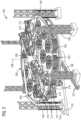
- FIG. 2 illustrates an internal perspective view of a portion of the direct air capture system 100.
- the internal perspective view illustrates components of the direct air capture system 100 disposed within the fixed structural shell 102.
- the direct air capture system 100 includes a frame 200 defining adsorption units 204 arranged around a central axis 208.
- the frame 200 includes an upper plate including outlet apertures and a lower plate including a corresponding number of inlet apertures.
- Adsorption cells 202 are positioned between the upper plate and the lower plate and are aligned with one of the inlet apertures and outlet apertures so that any flow through the unit passes through one of the adsorption cells 202.
- Several fasteners interconnect the upper plate and the lower plate to complete the assembly of the frame 200.
- Each adsorption unit 204 includes three adsorption cells 202 positioned within the frame 200 that seals the air passage so that the flow of air only flows through the adsorption cell 202. In the shown embodiment, there are six adsorption units 204 positioned within the frame 200, each adsorption unit 204 includes three adsorption cells 202. Of course, other constructions could include few than three adsorption cells 202 or more than three adsorption cells 202 as may be required.
- Each adsorption cell 202 includes a structural shell 402, or container, including an inlet at a first open end and an outlet at a second open end to allow air to flow through the adsorption cell 202 during an adsorption phase of the direct air capture.
- a hub 206 is coupled to the frame 200 and rotatable about a central axis 208.
- an arm 210 is attached to the hub 206.
- the arms 210 are carried by wheels 212 that roll in a track on the frame 200.
- the shown embodiment shows two Y-shaped upper arms 210 coupled to the hub 206 for co-rotation about the central axis 208.
- two Y-shaped lower arms 210 also are coupled to the hub for co-rotation about the central axis 208.
- the number of upper arms and lower arms is not limited to two upper arms and two lower arms. The number of upper arms and lower arms may be one or more each.
- Each Y-shaped arm 210 includes at least one lid 214 so that an upper lid 214 is coupled to the upper arm and a lower lid 214 is coupled to the lower arm.
- Both the upper lid 214 and the lower lid 214 are movable between an open position and a closed position. To get an upper lid and the lower lid to the closed position, the upper lid 214 is positioned to be concentric with the first open end of the adsorption cell 202 and the lower lid is positioned to be concentric with the second open end of the adsorption cell 202 by the rotation of the upper arm and the lower arm, respectively.
- the lids 214 then move toward and mate with a flat surface at the respective first open end or second open end of the adsorption cell 202 so that the respective first open end or second open end is covered.
- a first steam piping 216 is attached from an external source to the hub 206 and from the hub 206 to a port opening of an upper lid 214.
- a second steam piping 218 is attached from the port opening of a lower lid 214 to the hub 206 and from the hub 206 out to a position external to the fixed structural shell 102.
- a service arm 224 attached to the hub 206 may be equipped with a lifting device 220 that allows for easy removal of the container of the adsorption cell 202.
- the container may be lowered down to a service area in order to exchange it for another adsorption cell 202.
- Additional connections to the hub 206 including electrical, control, compressed air, water, drainage, etc., may be run through a channel 222 in order to keep the area near the ground surface clear during operation.
- FIG. 3 illustrates a zoomed in view of a rotating structure 300 of the direct air capture system 100 as shown in FIG. 2 .
- the rotating structure 300 includes the hub 206 that rotates about the central axis 208 and two lid arrangements, an upper lid arrangement 302 and a lower lid arrangement 304.
- the upper lid arrangement 302 and the lower lid arrangement 304 rotate independently of one another around the central axis 208.
- the rotating structure 300 rotates via an electrical motor driving the wheels 212.
- the rotation is controlled by a main controller that monitors and controls the direct air capture system 100.
- the upper lid arrangement 302 and the lower lid arrangements 304 of FIG. 3 co-rotate around the central axis 208.
- the upper lid arrangement 302 and the lower lid arrangement 304 each includes an arm 210 attached to the hub 206.
- Each arm 210 of the upper lid arrangement 302 and the lower lid arrangement 304 includes an upper lid or a lower lid, respectively, that may be positioned via rotation to mate with a surface 404 (shown in FIG. 4 ) of the structural shell 402 of the adsorption cell 202.
- the first steam piping 216 attaches from the hub 206 to each of the lids 214 of the upper lid arrangement 302.
- a door 306 within a central portion of the hub 206 may be used to access the lids 214 for inspection and exchange.
- FIG. 4 illustrates a perspective view of an adsorption cell 202.
- the adsorption cell 202 includes a structural shell 402 with a first opening 410 and a second opening (not shown) opposite the first opening 410 to allow for a through flow of air.
- the structural shell 402 may comprise a corrugated steel container.
- a surface 404 allows for mating with a corresponding lid 214.
- FIG. 4 only illustrates the first opening, however, the second opening also includes the surface 404 for mating with a corresponding lid 214.
- the surface 404 is wide enough to handle misalignments between the adsorption cell and the lid 214.
- Adjustable mounting hardware 406 is used to attach the adsorption cell 202 to the frame 200.
- the adsorption cell 202 also includes a sorbent element 408 installed within the structural shell 402.
- the adsorption cell 202 includes twenty sorbent elements 408, however, the adsorption cell 202 may include a range of 1-40 sorbent elements 408.
- FIG. 5 illustrates a perspective view of an individual sorbent element 408.
- Each sorbent element 408 includes a solid frame 502 that may be installed to hang inside the adsorption cell 202 from the structural shell 402.
- the solid frame 502 includes solid side portions 504 so that the flow of air is forced through a sorbent material 506 positioned within a cavity defined by the solid frame 502.
- FIG. 6 illustrates the sorbent material 506 within the sorbent element 408 according to the section defined by A-A of FIG. 5 .
- the sectional view shows the sorbent material 506 extending lengthwise folded in a wave pattern within the solid frame 502.
- the wave pattern allows for an increased amount of sorbent material 506 within the solid frame 502 while keeping the thickness of the sorbent material thin, such as between 2-10 mm thick, and the pressure drop minimal. For example, by using a large surface area as compared to a small thickness of the sorbent material, the volume of air flowing through the wave pattern of sorbent material is kept constant while the flow speed and the resistance from the sorbent material is lowered.
- the sorbent material 506 may be filled with a solid amine sorbent which is commonly used for removing CO2 from gas streams.
- the amine may be doped with polymer granules.
- the dimensions of the solid frame 502 as well as the number of folds of the sorbent material 506 may be varied based on the sorbent element 408 placement within the adsorption cell 202 in order to maximize the surface area and volume of the sorbent material 506.
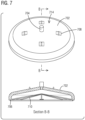
- FIG. 7 illustrates a perspective view of a lid 214.
- FIG 7 also includes a sectional view of the lid 214 defined by section B-B of FIG. 7 .
- the lid 214 includes a shell 702, a port opening 704, and a seal element 706.
- the seal element 706 cooperates with the surface 404 of the adsorption cell 202 to define a seal.
- the seal allows for an airtight connection with the adsorption cell 202 when aligned.
- the lid 214 is attached to the rotating structure 300 by adjustable mounting hardware 708 allowing for positional control.
- the lid 214 also includes a one-way valve 710 as shown in FIG. 8 .
- the valve 710 allows steam to flow into the adsorption cells 202 but inhibits air to enter the first steam piping 216.
- the valve 710 helps to minimize the volume that needs to be evacuated from the adsorption cell 202.
- the valve 710 may be a elastomeric lip valve or a duckbill valve or any other type of valve that performs the desired function.
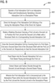
- FIG. 8 illustrates a flow chart describing a method for direct carbon dioxide capture 800.
- the method for direct air capture 800 operates a first adsorption cell in an adsorption phase and simultaneously operates a second adsorption cell in an desorption phase.
- air is directed through a first adsorption cell utilizing a fan during the absorption phase of the direct air capture.
- a rotating structure rotates carrying a first lid and a second lid to position the first lid and the second lid to mate with a structural shell of a corresponding second adsorption cell.
- the second adsorption cell is closed by covering each of a first open end and a second open end of the structural shell with the first lid or the second lid, respectively to seal the second adsorption cell.
- steam is fed into the second adsorption cell via a first steam piping and through the first lid.
- steam and carbon dioxide are extracted through the second lid and through a second steam piping.
- the first adsorption cell is uncovered in the adsorption phase while the second adsorption cell is covered by the first lid and the second lid in the desorption phase.
- a flow of air is drawn into the fixed structural shell 102 through the louvered siding 110 and then through a selected portion of adsorption cells 202 located internally within the fixed structural shell 102 and out through the first opening 104.
- the fan 106 operates to draw in the flow of air through the fixed structural shell 102 such that only the one fan is needed to operate the direct air capture system 100.
- the flow of air is vertically directed out of the first opening 104 away from the ground surface.
- all or two-thirds of the total adsorption cells operate in an adsorption phase, while none or one-third of the adsorption cells simultaneously operate in a desorption phase.
- the cells are grouped into six units with each unit including three cells. Two opposite units can operate in the desorption phase while the remaining four units operate in the adsorption phase.
- the lids 214 i.e., both the upper lids and lower lids, are in an open position so that the air flows through, each adsorption cell 202 of the first adsorption unit 204.
- carbon dioxide in the air flow may be adsorbed into the sorbent material 506 within each adsorption cell 202 of the first adsorption unit 204.
- the air is drawn through the sorbent material 506 of each adsorption cell 202 for approximately 1 hour and 40 minutes.
- a desorption phase is initiated, in the first adsorption unit.
- the rotating structure 300 rotates so that the lids 214, i.e, both upper lids and the lower lids, rotate to an aligned position and then translate to a closed position with a corresponding structural shell of the adsorption cell 202.
- the upper lid and the lower lid of each adsorption cell 202 are then placed in a closed position, so that the upper lids close a corresponding first open end of the corresponding adsorption cell 202 and the lower lid closes a corresponding second open end of the corresponding adsorption cell 202 to seal the structural shell 402.
- each closed adsorption cell 202 is raised to a range of 60-110 degrees Celsius and the partial pressure of the carbon dioxide within the cavity of closed adsorption cell 202 is reduced.
- the adsorption cell can be purged with another medium and/or the absolute pressure in the cavity of the closed adsorption cell can be lowered thereby reducing the amount of air that is mixed with the carbon dioxide to be delivered by the adsorption cell 202.
- Reducing the amount of air in the structural shell 402 may be accomplished using a vacuum pump by opening a valve in the second steam piping 218 that is connected to the vacuum pump.
- the valve to the vacuum pump is closed.
- the absolute pressure within the cavity of the closed adsorption cell 202 is lowered to 0.02-0.4 bar.
- the chosen pressure level sets the steam condensation temperature and is chosen based on the temperature of the available heat for steam generation.
- the vacuum also protects the sorbent material from degradation that would occur due to exposure to air.
- the steam is fed, into the structural shell 402 via the first steam piping 216 through the first lid from an external source.
- the steam has a temperature of between 90 and 110 degrees Celsius.
- carbon dioxide and steam are extracted, via a second steam piping 218 from the structural shell 402.
- the steam flow from the external source is switched off.
- the pressure in the second adsorption unit is lowered to a pressure less than 0.15 bar such that a drying/cooling phase is initiated. This drying/cooling phase allows adsorbed water to evaporate and the adsorption cell 202 to cool down.
- one adsorption unit i.e., the first adsorption unit
- multiple adsorption units may be utilized for the direct air capture system 100. For example, referring to FIG.
- the rotating structure 300 may be used so that a first adsorption unit and a second adsorption unit 204, each having at least one adsorption cell 202, may be in an adsorption phase, i.e., lids 214 in an open position, while a third adsorption unit 204 and a fourth adsorption unit 204, each having at least one adsorption cell 202, may be in a desorption phase, i.e., lids 214 in a closed position.
- the lids 214 used to close the third adsorption unit 204 and the fourth adsorption unit 204 may then be used to mate with and close the first adsorption unit 204 and the second adsorption unit 204 for the initiation of the desorption phase of these adsorption units 204.
- one lid 214 may be used for more than one adsorption cell 202.
- the ratio of the number of lids and the number of adsorption cell 202 may be chosen so that an optimal ratio of adsorption time to desorption time is achieved.
- each lid may be used for more than one adsorption cell. Heat loss is also reduced from other direct air capture systems by utilizing the steam feed through the rotating structure and the lid arrangements.
Landscapes
- Chemical & Material Sciences (AREA)
- Engineering & Computer Science (AREA)
- Analytical Chemistry (AREA)
- General Chemical & Material Sciences (AREA)
- Oil, Petroleum & Natural Gas (AREA)
- Chemical Kinetics & Catalysis (AREA)
- Environmental & Geological Engineering (AREA)
- Health & Medical Sciences (AREA)
- Biomedical Technology (AREA)
- Life Sciences & Earth Sciences (AREA)
- Sustainable Development (AREA)
- Separation Of Gases By Adsorption (AREA)
- Sampling And Sample Adjustment (AREA)
Abstract
A carbon dioxide capture unit includes a frame arranged to define a first adsorption unit and a second adsorption unit arranged around a central axis, a first adsorption cell disposed in the first adsorption unit and a second adsorption cell disposed in the second adsorption unit, each including a first opening and a second opening, a hub rotatably coupled to the frame for rotation around the central axis, an upper arm and a lower arm each coupled to the hub for co-rotation around the central axis, and an upper lid coupled to the upper arm and a lower lid coupled to the lower arm, both movable between an open position and a closed position. The upper arm and the lower arm are movable so that the upper and lower lids are positioned concentric with the first opening and the second opening, respectively.
Description
- Direct air capture is a process of capturing carbon dioxide (CO2) directly from an air stream. One method of direct air capture uses a sorbent to capture and remove the CO2 from the air stream upon contact. The disadvantages of this method of direct air capture include the high cost of the equipment, the high heat demand for the desorption and its high electricity demand.
- In accordance with one aspect, there is provided a carbon dioxide capture unit. The carbon dioxide capture unit includes a frame arranged to define a first adsorption unit and a second adsorption unit arranged around a central axis, a first adsorption cell disposed in the first adsorption unit and a second adsorption cell disposed in the second adsorption unit, the first adsorption cell and the second adsorption cell each including a first opening and a second opening, a hub rotatably coupled to the frame for rotation around the central axis, an upper arm coupled to the hub for co-rotation around the central axis, a lower arm coupled to the hub for co-rotation around the central axis, and an upper lid coupled to the upper arm and movable between an open position and a closed position. The upper arm and the lower arm are movable so that the upper and lower lid are positioned concentric with the first opening and the second opening, respectively, and movable to the closed position in response to operation in a desorption mode.
- In accordance with another aspect, there is provided a system of direct air capture of carbon dioxide. The system includes a fixed structure including an opening and a fan positioned in the opening operable to draw air into an inlet of the adsorption cell through sorbent material and out an outlet of the adsorption cell during an adsorption phase of the direct air capture so that the air flows through a wave pattern of the sorbent material. The fixed structure includes an adsorption cell positioned within the fixed structure, the adsorption cell includes a structural shell including an inlet at a first opening and an outlet at a second opening, a sorbent element including a solid frame installed within the structural shell, a sorbent material positioned within a cavity defined by the solid frame, the sorbent material disposed in a wave pattern, a first lid movable between an adsorption position in which the first lid sealing covers the first opening, and a second lid movable between an adsorption position and a desorption position in which the second lid sealing covers the second opening.
- In accordance with a further aspect, a method for direct air capture of carbon dioxide is provided. The method includes the steps of operating a first adsorption cell in an adsorption phase and simultaneously operating a second adsorption cell in an desorption phase whereby the first adsorption cell is uncovered and in the adsorption phase while the second adsorption cell is covered by the first lid and the second lid in the desorption phase, directing air through the first adsorption cell utilizing a fan during the absorption phase of the direct air capture, rotating a rotating structure carrying a first lid and a second lid to position the first lid and the second lid to mate with a structural shell of a corresponding second adsorption cell, closing the second adsorption cell by covering each of a first open end and a second open end of the structural shell with the first lid or the second lid, respectively, to seal the second adsorption cell, feeding steam into the second adsorption cell via a first steam piping and through the first lid, and extracting steam and carbon dioxide through the second lid and through a second steam piping.
- To easily identify the discussion of any particular element or act, the most significant digit or digits in a reference number refer to the figure number in which that element is first introduced.
-
FIG. 1 illustrates an external perspective view of a direct air capture system. -
FIG. 2 illustrates an internal perspective view of a direct air capture system. -
FIG. 3 illustrates a perspective view of a rotating structure. -
FIG. 4 illustrates a perspective view of an adsorption cell. -
FIG. 5 illustrates an embodiment of a sorbent element. -
FIG. 6 illustrates a sectional view of the sorbent element ofFIG. 5 . -
FIG. 7 illustrates an aspect of the subject matter in accordance with one embodiment. -
FIG. 8 illustrates a method fordirect air capture 800 in accordance with one embodiment. - One process for carbon dioxide capturing from ambient air includes having a solid sorbent to which the carbon dioxide molecules can adsorb through reactions with amine groups. Other sorbents may also be used in the process including, but not limited to, structures with micropores acting as molecular sieves. During adsorption, air needs to be moved around the sorbent to provide carbon dioxide in air to the sorbent so that it can be adsorbed. During desorption, the sorbent with the adsorbed carbon dioxide needs to be enclosed in a container so that released carbon dioxide can be captured. To desorb, the temperature is raised and the partial pressure of the CO2 is lowered. The latter can be done by purging with another medium and/or lowering the absolute pressure in the sorbent container. In the foregoing process, steam is used for both purging and heating of the sorbent. At the start of the desorption phase, the air pressure in the sorbent container may be lowered using a vacuum pump, thereby lowering the amount of air that is mixed with the CO2 to be delivered by the unit.
-
FIG. 1 illustrates a perspective view of a directair capture system 100 as viewed externally. The directair capture system 100 is housed by a fixedstructural shell 102. In the shown embodiment, the fixedstructural shell 102 is cylindrical in shape. The fixedstructural shell 102 includes afirst opening 104 and asecond opening 114 to allow a through flow of air. Asingle fan 106 is positioned in thefirst opening 104. Thefan 106 is utilized to draw in a flow of air, shown by arrows, through the fixedstructural shell 102. All of the internal components of the directair capture system 100 are carried by the fixedstructural shell 102 mounted onlegs 108 so that the fixedstructural shell 102 is above a ground surface. In an embodiment, the fixedstructural shell 102 is several meters above the ground surface to minimize inflow and air recirculation. Betweenadjacent legs 108 and between the fixedstructural shell 102 and the ground surface is alouvered siding 110 attached to the fixedstructural shell 102 to allow the flow of air into the fixedstructural shell 102 at thesecond opening 114 while protecting the directair capture system 100 from unauthorized entrance of people and animals, for example. Access to technical personnel may be allowed by removing a section of thelouvered siding 110. An air filter may also be disposed adjacent to thelouvered siding 110 if desired. Just inside thefirst opening 104, a raindefense louvre unit 112 may be positioned within the fixedstructural shell 102 adjacent to thefan 106 to inhibit water from entering the fixedstructural shell 102. -
FIG. 2 illustrates an internal perspective view of a portion of the directair capture system 100. The internal perspective view illustrates components of the directair capture system 100 disposed within the fixedstructural shell 102. The directair capture system 100 includes aframe 200 definingadsorption units 204 arranged around acentral axis 208. Theframe 200 includes an upper plate including outlet apertures and a lower plate including a corresponding number of inlet apertures.Adsorption cells 202 are positioned between the upper plate and the lower plate and are aligned with one of the inlet apertures and outlet apertures so that any flow through the unit passes through one of theadsorption cells 202. Several fasteners interconnect the upper plate and the lower plate to complete the assembly of theframe 200. Eachadsorption unit 204 includes threeadsorption cells 202 positioned within theframe 200 that seals the air passage so that the flow of air only flows through theadsorption cell 202. In the shown embodiment, there are sixadsorption units 204 positioned within theframe 200, eachadsorption unit 204 includes threeadsorption cells 202. Of course, other constructions could include few than threeadsorption cells 202 or more than threeadsorption cells 202 as may be required. Eachadsorption cell 202 includes astructural shell 402, or container, including an inlet at a first open end and an outlet at a second open end to allow air to flow through theadsorption cell 202 during an adsorption phase of the direct air capture. - A
hub 206 is coupled to theframe 200 and rotatable about acentral axis 208. In addition, anarm 210 is attached to thehub 206. In the shown embodiment, thearms 210 are carried bywheels 212 that roll in a track on theframe 200. The shown embodiment shows two Y-shapedupper arms 210 coupled to thehub 206 for co-rotation about thecentral axis 208. Although only partially shown, two Y-shapedlower arms 210 also are coupled to the hub for co-rotation about thecentral axis 208. However, the number of upper arms and lower arms is not limited to two upper arms and two lower arms. The number of upper arms and lower arms may be one or more each. Each Y-shaped arm 210 includes at least onelid 214 so that anupper lid 214 is coupled to the upper arm and alower lid 214 is coupled to the lower arm. In the shown embodiment, only theupper lids 214 are shown. Both theupper lid 214 and thelower lid 214 are movable between an open position and a closed position. To get an upper lid and the lower lid to the closed position, theupper lid 214 is positioned to be concentric with the first open end of theadsorption cell 202 and the lower lid is positioned to be concentric with the second open end of theadsorption cell 202 by the rotation of the upper arm and the lower arm, respectively. Thelids 214 then move toward and mate with a flat surface at the respective first open end or second open end of theadsorption cell 202 so that the respective first open end or second open end is covered. - A first steam piping 216 is attached from an external source to the
hub 206 and from thehub 206 to a port opening of anupper lid 214. Likewise, a second steam piping 218 is attached from the port opening of alower lid 214 to thehub 206 and from thehub 206 out to a position external to the fixedstructural shell 102. - A
service arm 224 attached to thehub 206 may be equipped with alifting device 220 that allows for easy removal of the container of theadsorption cell 202. The container may be lowered down to a service area in order to exchange it for anotheradsorption cell 202. Additional connections to thehub 206 including electrical, control, compressed air, water, drainage, etc., may be run through achannel 222 in order to keep the area near the ground surface clear during operation. -
FIG. 3 illustrates a zoomed in view of arotating structure 300 of the directair capture system 100 as shown inFIG. 2 . Therotating structure 300 includes thehub 206 that rotates about thecentral axis 208 and two lid arrangements, anupper lid arrangement 302 and alower lid arrangement 304. In an embodiment, theupper lid arrangement 302 and thelower lid arrangement 304 rotate independently of one another around thecentral axis 208. Therotating structure 300 rotates via an electrical motor driving thewheels 212. The rotation is controlled by a main controller that monitors and controls the directair capture system 100. Theupper lid arrangement 302 and thelower lid arrangements 304 ofFIG. 3 co-rotate around thecentral axis 208. Theupper lid arrangement 302 and thelower lid arrangement 304 each includes anarm 210 attached to thehub 206. Eacharm 210 of theupper lid arrangement 302 and thelower lid arrangement 304 includes an upper lid or a lower lid, respectively, that may be positioned via rotation to mate with a surface 404 (shown inFIG. 4 ) of thestructural shell 402 of theadsorption cell 202. The first steam piping 216, as shown inFIG. 3 , attaches from thehub 206 to each of thelids 214 of theupper lid arrangement 302. Adoor 306 within a central portion of thehub 206 may be used to access thelids 214 for inspection and exchange. -
FIG. 4 illustrates a perspective view of anadsorption cell 202. Theadsorption cell 202 includes astructural shell 402 with afirst opening 410 and a second opening (not shown) opposite thefirst opening 410 to allow for a through flow of air. Thestructural shell 402 may comprise a corrugated steel container. At each of thefirst opening 410 and the second opening asurface 404 allows for mating with acorresponding lid 214.FIG. 4 only illustrates the first opening, however, the second opening also includes thesurface 404 for mating with acorresponding lid 214. Thesurface 404 is wide enough to handle misalignments between the adsorption cell and thelid 214. Adjustable mountinghardware 406 is used to attach theadsorption cell 202 to theframe 200. Theadsorption cell 202 also includes asorbent element 408 installed within thestructural shell 402. In the shown embodiment, theadsorption cell 202 includes twentysorbent elements 408, however, theadsorption cell 202 may include a range of 1-40sorbent elements 408. -
FIG. 5 illustrates a perspective view of anindividual sorbent element 408. Eachsorbent element 408 includes asolid frame 502 that may be installed to hang inside theadsorption cell 202 from thestructural shell 402. Thesolid frame 502 includessolid side portions 504 so that the flow of air is forced through asorbent material 506 positioned within a cavity defined by thesolid frame 502. -
FIG. 6 illustrates thesorbent material 506 within thesorbent element 408 according to the section defined by A-A ofFIG. 5 . The sectional view shows thesorbent material 506 extending lengthwise folded in a wave pattern within thesolid frame 502. The wave pattern allows for an increased amount ofsorbent material 506 within thesolid frame 502 while keeping the thickness of the sorbent material thin, such as between 2-10 mm thick, and the pressure drop minimal. For example, by using a large surface area as compared to a small thickness of the sorbent material, the volume of air flowing through the wave pattern of sorbent material is kept constant while the flow speed and the resistance from the sorbent material is lowered. - The
sorbent material 506 may be filled with a solid amine sorbent which is commonly used for removing CO2 from gas streams. The amine may be doped with polymer granules. - The dimensions of the
solid frame 502 as well as the number of folds of thesorbent material 506 may be varied based on thesorbent element 408 placement within theadsorption cell 202 in order to maximize the surface area and volume of thesorbent material 506. -
FIG. 7 illustrates a perspective view of alid 214.FIG 7 also includes a sectional view of thelid 214 defined by section B-B ofFIG. 7 . Thelid 214 includes ashell 702, aport opening 704, and aseal element 706. Theseal element 706 cooperates with thesurface 404 of theadsorption cell 202 to define a seal. The seal allows for an airtight connection with theadsorption cell 202 when aligned. Thelid 214 is attached to therotating structure 300 by adjustable mountinghardware 708 allowing for positional control. Thelid 214 also includes a one-way valve 710 as shown inFIG. 8 . For the upper lids, thevalve 710 allows steam to flow into theadsorption cells 202 but inhibits air to enter the first steam piping 216. For the lower lids, thevalve 710 helps to minimize the volume that needs to be evacuated from theadsorption cell 202. In an embodiment, thevalve 710 may be a elastomeric lip valve or a duckbill valve or any other type of valve that performs the desired function. -
FIG. 8 illustrates a flow chart describing a method for directcarbon dioxide capture 800. Inblock 802, the method fordirect air capture 800 operates a first adsorption cell in an adsorption phase and simultaneously operates a second adsorption cell in an desorption phase. Inblock 804, air is directed through a first adsorption cell utilizing a fan during the absorption phase of the direct air capture. Inblock 806, a rotating structure rotates carrying a first lid and a second lid to position the first lid and the second lid to mate with a structural shell of a corresponding second adsorption cell. Inblock 808, the second adsorption cell is closed by covering each of a first open end and a second open end of the structural shell with the first lid or the second lid, respectively to seal the second adsorption cell. Inblock 810, steam is fed into the second adsorption cell via a first steam piping and through the first lid. Inblock 812, steam and carbon dioxide are extracted through the second lid and through a second steam piping. Inblock 814, the first adsorption cell is uncovered in the adsorption phase while the second adsorption cell is covered by the first lid and the second lid in the desorption phase. - The following description of the method for direct
carbon dioxide capture 800 referencesFIGs. 1-8 . In operation, a flow of air is drawn into the fixedstructural shell 102 through thelouvered siding 110 and then through a selected portion ofadsorption cells 202 located internally within the fixedstructural shell 102 and out through thefirst opening 104. Thefan 106 operates to draw in the flow of air through the fixedstructural shell 102 such that only the one fan is needed to operate the directair capture system 100. In the embodiment shown inFIG. 1 , the flow of air is vertically directed out of thefirst opening 104 away from the ground surface. - During operation of the illustrated arrangement, all or two-thirds of the total adsorption cells operate in an adsorption phase, while none or one-third of the adsorption cells simultaneously operate in a desorption phase. Specifically, the cells are grouped into six units with each unit including three cells. Two opposite units can operate in the desorption phase while the remaining four units operate in the adsorption phase.
- For those cells in the adsorption phase, the
lids 214, i.e., both the upper lids and lower lids, are in an open position so that the air flows through, eachadsorption cell 202 of thefirst adsorption unit 204. During a time period in which thelids 214 are in the open position, carbon dioxide in the air flow may be adsorbed into thesorbent material 506 within eachadsorption cell 202 of thefirst adsorption unit 204. In an embodiment, the air is drawn through thesorbent material 506 of eachadsorption cell 202 for approximately 1 hour and 40 minutes. - After a time period in the adsorption phase, a desorption phase is initiated, in the first adsorption unit. The
rotating structure 300 rotates so that thelids 214, i.e, both upper lids and the lower lids, rotate to an aligned position and then translate to a closed position with a corresponding structural shell of theadsorption cell 202. The upper lid and the lower lid of eachadsorption cell 202 are then placed in a closed position, so that the upper lids close a corresponding first open end of the correspondingadsorption cell 202 and the lower lid closes a corresponding second open end of the correspondingadsorption cell 202 to seal thestructural shell 402. - During the desorption phase, the temperature within each
closed adsorption cell 202 is raised to a range of 60-110 degrees Celsius and the partial pressure of the carbon dioxide within the cavity ofclosed adsorption cell 202 is reduced. In order to reduce the partial pressure of the carbon dioxide in the closed adsorption cell, the adsorption cell can be purged with another medium and/or the absolute pressure in the cavity of the closed adsorption cell can be lowered thereby reducing the amount of air that is mixed with the carbon dioxide to be delivered by theadsorption cell 202. Reducing the amount of air in thestructural shell 402 may be accomplished using a vacuum pump by opening a valve in the second steam piping 218 that is connected to the vacuum pump. When the desired pressure level is reached, the valve to the vacuum pump is closed. In an embodiment, the absolute pressure within the cavity of theclosed adsorption cell 202 is lowered to 0.02-0.4 bar. The chosen pressure level sets the steam condensation temperature and is chosen based on the temperature of the available heat for steam generation. In addition to allowing the carbon dioxide to be captured within the sorbent container, the vacuum also protects the sorbent material from degradation that would occur due to exposure to air. - With the
lids 214 in the closed position, steam is fed, into thestructural shell 402 via the first steam piping 216 through the first lid from an external source. In an embodiment, the steam has a temperature of between 90 and 110 degrees Celsius. Through the second lid, carbon dioxide and steam are extracted, via a second steam piping 218 from thestructural shell 402. After feeding steam into the first lid for a desired time, the steam flow from the external source is switched off. The pressure in the second adsorption unit is lowered to a pressure less than 0.15 bar such that a drying/cooling phase is initiated. This drying/cooling phase allows adsorbed water to evaporate and theadsorption cell 202 to cool down. - With regards to the direct air capture system's 100 operational description described above, one adsorption unit, i.e., the first adsorption unit, was referenced. However, multiple adsorption units may be utilized for the direct
air capture system 100. For example, referring toFIG. 2 , the rotatingstructure 300 may be used so that a first adsorption unit and asecond adsorption unit 204, each having at least oneadsorption cell 202, may be in an adsorption phase, i.e.,lids 214 in an open position, while athird adsorption unit 204 and afourth adsorption unit 204, each having at least oneadsorption cell 202, may be in a desorption phase, i.e.,lids 214 in a closed position. Through rotation of therotating structure 300, thelids 214 used to close thethird adsorption unit 204 and thefourth adsorption unit 204 may then be used to mate with and close thefirst adsorption unit 204 and thesecond adsorption unit 204 for the initiation of the desorption phase of theseadsorption units 204. In this way, onelid 214 may be used for more than oneadsorption cell 202. The ratio of the number of lids and the number ofadsorption cell 202 may be chosen so that an optimal ratio of adsorption time to desorption time is achieved. - The proposed direct air capture system utilizes the components of the system as much as possible. For example, each lid may be used for more than one adsorption cell. Heat loss is also reduced from other direct air capture systems by utilizing the steam feed through the rotating structure and the lid arrangements.
Claims (20)
- A carbon dioxide capture unit, the unit comprising:a frame arranged to define a first adsorption unit and a second adsorption unit arranged around a central axis;a first adsorption cell disposed in the first adsorption unit and a second adsorption cell disposed in the second adsorption unit, the first adsorption cell and the second adsorption cell each including a first opening and a second opening;a hub rotatably coupled to the frame for rotation around the central axis;an upper arm coupled to the hub for co-rotation around the central axis;a lower arm coupled to the hub for co-rotation around the central axis;an upper lid coupled to the upper arm and movable between an open position and a closed position; anda lower lid coupled to the lower arm and movable between an open position and a closed position,wherein the upper arm and the lower arm are movable so that the upper lid and lower lid are positioned concentric with the first opening and the second opening, respectively, and movable to the closed position in response to operation in a desorption mode.
- The carbon dioxide capture unit of claim 1, wherein each of the upper lid and the lower lid comprises a shell, a port opening, and a seal element that selectively cooperates with a surface of one of the first adsorption unit and the second adsorption unit to define a seal.
- The carbon dioxide capture unit of claim 2, further comprising a first steam piping attached to the hub and from the hub to the port opening of the upper lid, wherein the first steam piping provides steam from an external steam source to the upper lid via the hub.
- The carbon dioxide capture unit of claim 3, further comprising a second steam piping attached from the port opening of the lower lid to the hub and from the hub to a position external to the carbon dioxide capture unit, wherein the second steam piping is arranged to discharge steam and carbon dioxide from the carbon dioxide capture unit.
- The carbon dioxide capture unit of claim 1, wherein the first adsorption unit includes a third adsorption cell and a fourth adsorption cell, and the second adsorption unit includes a fifth adsorption cell and a sixth adsorption cell.
- The carbon dioxide capture unit of claim 1, further comprising a service arm including a lifting device for removing a structural shell of the first adsorption cell or the second adsorption cell.
- The carbon dioxide capture unit of claim 2, wherein the shells move linearly when positioned concentric with the first opening and the second opening and then move, while remaining concentric, toward the respective surface, and wherein when the shells mate with the surface, the seal element cooperates with the surface to seal the shell to the surface.
- A system for direct air capture of carbon dioxide, comprising:
a fixed structure including an opening, the fixed structure comprising:an adsorption cell positioned within the fixed structure, the adsorption cell includes a structural shell including an inlet at a first opening and an outlet at a second opening,a sorbent element including a solid frame installed within the structural shell,a sorbent material positioned within a cavity defined by the solid frame, the sorbent material disposed in a wave pattern,a first lid movable between an adsorption position and a desorption position in which the first lid sealing covers the first opening anda second lid movable between an adsorption position and a desorption position in which the second lid sealing covers the second opening; anda fan positioned in the opening operable to draw air into the inlet through the sorbent material and out the outlet during an adsorption phase of the direct air capture so that the air flows through the wave pattern of sorbent material. - The system of claim 8, further comprising:
a rotating structure comprising:a hub centrally located within the fixed structure and rotatable about a central axis, anda lid arrangement comprising:wherein the first lid or the second lid is positionable by rotation of the arm to mate with the structural shell of the adsorption cell.
an arm attached to the hub, the arm and the hub co-rotating about the central axis, the arm carrying the first lid or the second lid, - The system as claimed in claim 9, wherein the system includes two lid arrangements, a first lid arrangement having the first lid positioned to mate with the first opening and a second lid arrangement having the second lid positioned to mate with the second opening.
- The system as claimed in claim 10, wherein each of the first lid and the second lid comprises a structural shell, a port opening, and a seal allowing for an airtight connection with the corresponding adsorption cell.
- The system as claimed in claim 11, further comprising a first steam piping attached source to the hub to deliver steam thereto and extending from the hub to the port opening of the first lid via the hub.
- The system as claimed in claim 12, further comprising a second steam piping attached from the port opening of the second lid to the hub and from the hub to a position external to the fixed structure.
- The system as claimed in claim 8, wherein the sorbent material is a solid amine loaded sorbent.
- The system as claimed in claim 8, wherein the fixed structure comprises a fixed structural shell that defines the opening and a louvred siding attached to the fixed structural shell and positioned between the fixed structural shell and a ground surface that includes a further opening to allow a flow of air into the fixed structural shell.
- A method for direct air capture of carbon dioxide, comprising:operating a first adsorption cell in an adsorption phase and simultaneously operating a second adsorption cell in a desorption phase;directing air through the first adsorption cell utilizing a fan during the absorption phase of the direct air capture;rotating a rotating structure carrying a first lid and a second lid to position the first lid and the second lid to mate with a structural shell of a corresponding second adsorption cell;closing the second adsorption cell by covering each of a first open end and a second open end of the structural shell with the first lid or the second lid, respectively, to seal the second adsorption cell;feeding steam into the second adsorption cell via a first steam piping and through the first lid; andextracting steam and carbon dioxide through the second lid and through a second steam piping,wherein the first adsorption cell is uncovered and in the adsorption phase while the second adsorption cell is covered by the first lid and the second lid in the desorption phase.
- The method of claim 16, further comprising:lowering an absolute pressure within one of the first adsorption cell and the second adsorption cell that is operating during the desorption phase prior to the step of feeding steam into the one of the first adsorption cell and the second adsorption cell,wherein the absolute pressure within the one of the first adsorption cell and second adsorption cell is lowered to a range of 0.02-0.4 bar.
- The method of claim 16, further comprising:lowering an absolute pressure within the one of the first adsorption cell and the second adsorption cell after the step of feeding steam, and allowing the one of the first adsorption cell and second adsorption cell to reach a desired temperature,wherein the absolute pressure within the one of the first adsorption cell and the second adsorption cell is lowered to <0.5 bar.
- The method of claim 16, wherein the rotating step includes:coupling a first arm and a second arm to the hub, the arms co-rotating about the central axis, each arm carrying the first lid or the second lid,rotating a centrally located hub about a central axis so that the first arm and the second arm rotate, andpositioning, by the rotation of the first arm and the second arm, the first lid and the second lid to mate with the structural shell of the first adsorption cell or the second adsorption cell.
- The method of claim 19, wherein the positioning includes moving the first lid and the second lid to a closed position by moving the first lid and the second lid toward the first open end and second open end, respectively.
Priority Applications (8)
| Application Number | Priority Date | Filing Date | Title |
|---|---|---|---|
| EP22153483.7A EP4218989A1 (en) | 2022-01-26 | 2022-01-26 | Unit for direct capture of carbon dioxide |
| EP23701437.8A EP4440725B1 (en) | 2022-01-26 | 2023-01-20 | Direct air capture system |
| PCT/EP2023/051302 WO2023144018A1 (en) | 2022-01-26 | 2023-01-20 | Direct air capture system |
| AU2023211002A AU2023211002B2 (en) | 2022-01-26 | 2023-01-20 | Direct air capture system |
| US18/728,880 US12257547B2 (en) | 2022-01-26 | 2023-01-20 | Direct air capture system |
| CN202380018637.0A CN118591410B (en) | 2022-01-26 | 2023-01-20 | Direct air capture systems |
| CA3244418A CA3244418C (en) | 2022-01-26 | 2023-01-20 | Direct air capture system |
| CL2024002228A CL2024002228A1 (en) | 2022-01-26 | 2024-07-24 | Direct air capture system |
Applications Claiming Priority (1)
| Application Number | Priority Date | Filing Date | Title |
|---|---|---|---|
| EP22153483.7A EP4218989A1 (en) | 2022-01-26 | 2022-01-26 | Unit for direct capture of carbon dioxide |
Publications (1)
| Publication Number | Publication Date |
|---|---|
| EP4218989A1 true EP4218989A1 (en) | 2023-08-02 |
Family
ID=80035161
Family Applications (2)
| Application Number | Title | Priority Date | Filing Date |
|---|---|---|---|
| EP22153483.7A Pending EP4218989A1 (en) | 2022-01-26 | 2022-01-26 | Unit for direct capture of carbon dioxide |
| EP23701437.8A Active EP4440725B1 (en) | 2022-01-26 | 2023-01-20 | Direct air capture system |
Family Applications After (1)
| Application Number | Title | Priority Date | Filing Date |
|---|---|---|---|
| EP23701437.8A Active EP4440725B1 (en) | 2022-01-26 | 2023-01-20 | Direct air capture system |
Country Status (6)
| Country | Link |
|---|---|
| US (1) | US12257547B2 (en) |
| EP (2) | EP4218989A1 (en) |
| CN (1) | CN118591410B (en) |
| AU (1) | AU2023211002B2 (en) |
| CL (1) | CL2024002228A1 (en) |
| WO (1) | WO2023144018A1 (en) |
Cited By (1)
| Publication number | Priority date | Publication date | Assignee | Title |
|---|---|---|---|---|
| EP4635597A1 (en) * | 2024-04-17 | 2025-10-22 | Siemens Energy Global GmbH & Co. KG | Filter system for reduction of airborne particles for use in direct air carbon capture |
Families Citing this family (5)
| Publication number | Priority date | Publication date | Assignee | Title |
|---|---|---|---|---|
| CA3252286A1 (en) * | 2022-06-24 | 2023-12-28 | Climeworks Ag | Direct air capture device |
| EP4552729A1 (en) | 2023-11-10 | 2025-05-14 | Noratu GmbH | Method and apparatus for dynamically controlled passive absorption of carbon dioxide from the atmosphere using artificial intelligence: dynamic passive absorption tower technology (dpat) |
| EP4585293A1 (en) | 2024-01-12 | 2025-07-16 | Siemens Energy Global GmbH & Co. KG | Method for operating a direct air capture plant and direct air capture plant |
| WO2026018196A2 (en) | 2024-07-17 | 2026-01-22 | Carpecarbon S.R.L. Societa' Benefit | System and method for the capture of carbon dioxide from an aeriform mixture |
| EP4706800A1 (en) | 2024-09-06 | 2026-03-11 | Siemens Energy Global GmbH & Co. KG | An energy efficient indirect heating process for direct air capture applications |
Citations (4)
| Publication number | Priority date | Publication date | Assignee | Title |
|---|---|---|---|---|
| US3504483A (en) * | 1967-09-08 | 1970-04-07 | Hitachi Ltd | Apparatus for the removal of sulfur oxides from waste gases |
| US20160101387A1 (en) * | 2014-10-10 | 2016-04-14 | Meta Industrial Inc. | Dehumidifying apparatus |
| CN108096990A (en) * | 2016-11-25 | 2018-06-01 | 中国石油化工股份有限公司 | A kind of adsorption separation device |
| US20180250609A1 (en) * | 2017-03-03 | 2018-09-06 | Baisheng Zou | Rotary solid/fluid counter-current contacting apparatus |
Family Cites Families (17)
| Publication number | Priority date | Publication date | Assignee | Title |
|---|---|---|---|---|
| US4589892A (en) * | 1983-04-07 | 1986-05-20 | Bry-Air, Inc. | Sequenced modular bed carousel dehumidifier |
| US4793830A (en) * | 1987-12-28 | 1988-12-27 | Murphy Milton K | Process for producing high quality gas for instrumentation application using gas separation membranes |
| US5862819A (en) * | 1996-01-11 | 1999-01-26 | Cradeur; Robert R. | Mobile apparatus for removing hazardous gases from enclosed structures |
| US6245214B1 (en) * | 1998-09-18 | 2001-06-12 | Alliedsignal Inc. | Electro-catalytic oxidation (ECO) device to remove CO from reformate for fuel cell application |
| US6824590B2 (en) * | 2000-11-07 | 2004-11-30 | Air Products And Chemicals, Inc. | Use of lithium-containing fau in air separation processes including water and/or carbon dioxide removal |
| JP3994157B2 (en) * | 2003-02-17 | 2007-10-17 | 独立行政法人産業技術総合研究所 | Method and apparatus for purifying gases containing organic contaminants |
| US20140205524A1 (en) * | 2013-01-24 | 2014-07-24 | David Sevier | Gas Component Extraction from Gas Mixture |
| EP3089809A4 (en) * | 2013-12-31 | 2017-10-25 | Chichilnisky, Graciela | Rotating multi-monolith bed movement system for removing co2 from the atmosphere |
| CN106488795B (en) * | 2014-06-03 | 2020-03-13 | 克莱姆沃克斯有限公司 | Direct air capture device |
| FR3029803B1 (en) * | 2014-12-11 | 2019-09-27 | L'air Liquide, Societe Anonyme Pour L'etude Et L'exploitation Des Procedes Georges Claude | ADSORBENT MIXTURE WITH ENHANCED THERMAL CAPACITY |
| CN106492589A (en) * | 2016-12-13 | 2017-03-15 | 中山大学 | CO2 adsorption/desorption cycle treatment device, preparation method and treatment method thereof |
| KR101807717B1 (en) * | 2017-01-20 | 2017-12-13 | 한국에너지기술연구원 | Movable adsorption and desorption apparatus |
| WO2019161420A1 (en) | 2018-01-26 | 2019-08-22 | Eisenberger, Peter And Chichilnisky, Graciela, Jointly | A methodology and system for optimising and improving the cost and performance of direct air carbon dioxide capture systems, thereby contributing to a lessening of the threat of catastrophic climate change |
| CN108607324B (en) * | 2018-03-28 | 2021-01-01 | 广西艾尚嘉家居有限公司 | A bed with formaldehyde adsorption function |
| EP3725391B1 (en) | 2019-04-18 | 2021-05-26 | Climeworks AG | High troughput direct air capture device for capturing co2 from air and method of its operation |
| EP3791950A1 (en) * | 2019-09-11 | 2021-03-17 | Vito NV | System for direct carbon dioxide capture |
| CN112169537A (en) | 2020-09-27 | 2021-01-05 | 上海交通大学 | Rapid temperature swing adsorption rotary wheel type direct air carbon dioxide capture system and method |
-
2022
- 2022-01-26 EP EP22153483.7A patent/EP4218989A1/en active Pending
-
2023
- 2023-01-20 EP EP23701437.8A patent/EP4440725B1/en active Active
- 2023-01-20 CN CN202380018637.0A patent/CN118591410B/en active Active
- 2023-01-20 AU AU2023211002A patent/AU2023211002B2/en active Active
- 2023-01-20 WO PCT/EP2023/051302 patent/WO2023144018A1/en not_active Ceased
- 2023-01-20 US US18/728,880 patent/US12257547B2/en active Active
-
2024
- 2024-07-24 CL CL2024002228A patent/CL2024002228A1/en unknown
Patent Citations (4)
| Publication number | Priority date | Publication date | Assignee | Title |
|---|---|---|---|---|
| US3504483A (en) * | 1967-09-08 | 1970-04-07 | Hitachi Ltd | Apparatus for the removal of sulfur oxides from waste gases |
| US20160101387A1 (en) * | 2014-10-10 | 2016-04-14 | Meta Industrial Inc. | Dehumidifying apparatus |
| CN108096990A (en) * | 2016-11-25 | 2018-06-01 | 中国石油化工股份有限公司 | A kind of adsorption separation device |
| US20180250609A1 (en) * | 2017-03-03 | 2018-09-06 | Baisheng Zou | Rotary solid/fluid counter-current contacting apparatus |
Cited By (2)
| Publication number | Priority date | Publication date | Assignee | Title |
|---|---|---|---|---|
| EP4635597A1 (en) * | 2024-04-17 | 2025-10-22 | Siemens Energy Global GmbH & Co. KG | Filter system for reduction of airborne particles for use in direct air carbon capture |
| WO2025218955A1 (en) * | 2024-04-17 | 2025-10-23 | Siemens Energy Global GmbH & Co. KG | Filter system for reduction of airborne particles for use in direct air carbon capture |
Also Published As
| Publication number | Publication date |
|---|---|
| US20250001357A1 (en) | 2025-01-02 |
| EP4440725A1 (en) | 2024-10-09 |
| CN118591410B (en) | 2025-08-29 |
| CA3244418A1 (en) | 2023-08-03 |
| WO2023144018A1 (en) | 2023-08-03 |
| AU2023211002B2 (en) | 2024-07-25 |
| EP4440725B1 (en) | 2026-03-04 |
| CN118591410A (en) | 2024-09-03 |
| US12257547B2 (en) | 2025-03-25 |
| AU2023211002A1 (en) | 2024-06-27 |
| EP4440725C0 (en) | 2026-03-04 |
| CL2024002228A1 (en) | 2025-01-10 |
Similar Documents
| Publication | Publication Date | Title |
|---|---|---|
| US12257547B2 (en) | Direct air capture system | |
| EP4360741A1 (en) | System for direct air capture of carbon dioxide | |
| EP3151947B1 (en) | Vacuum chamber for direct air capture device | |
| US12312778B2 (en) | Atmospheric water harvesting device and method | |
| CN111765574A (en) | New energy low-humidity clean workshop and energy-saving air conditioning system | |
| CA3244418C (en) | Direct air capture system | |
| CN215637668U (en) | device for humidity control | |
| CN219308339U (en) | Continuous VOCs waste gas resin runner adsorption and desorption device | |
| CN217482901U (en) | Polyester fiber membrane dehumidification equipment | |
| CN215522074U (en) | Two-way rotary wing valve | |
| CN212299291U (en) | New energy low-humidity clean workshop and energy-saving air conditioning system | |
| CN209341408U (en) | A kind of novel constant-temperature constant wetting air conditioner unit | |
| CN113144881A (en) | Assembled tail gas treatment cabinet | |
| CN119425257B (en) | Volatile organic compound treatment system | |
| CN215185375U (en) | An intelligent low-voltage power distribution device cabinet top protective structure | |
| CN213960545U (en) | Electrical cabinet used in humid environment | |
| CN216320078U (en) | Multifunctional crystallization separation device | |
| CN118987857B (en) | A waste gas treatment device in the production of waterproof membrane | |
| CN216048104U (en) | Dehumidification system applied to 2% low-humidity area | |
| US4262655A (en) | Cylindrical rotary controller for a solar heat system | |
| CN119333281A (en) | A box-type generator set with closed ventilation function | |
| CN112833220A (en) | Two-way rotary wing valve | |
| CN122032264A (en) | Circulated carbon dioxide of airtight space adsorbs entrapment device | |
| CN121520675A (en) | An oxygen-enriching device and an air conditioner equipped with the oxygen-enriching device | |
| CN122059295A (en) | Sheet material collecting device |
Legal Events
| Date | Code | Title | Description |
|---|---|---|---|
| PUAI | Public reference made under article 153(3) epc to a published international application that has entered the european phase |
Free format text: ORIGINAL CODE: 0009012 |
|
| STAA | Information on the status of an ep patent application or granted ep patent |
Free format text: STATUS: THE APPLICATION HAS BEEN PUBLISHED |
|
| AK | Designated contracting states |
Kind code of ref document: A1 Designated state(s): AL AT BE BG CH CY CZ DE DK EE ES FI FR GB GR HR HU IE IS IT LI LT LU LV MC MK MT NL NO PL PT RO RS SE SI SK SM TR |