EP4218965A1 - Adjustable weight club head - Google Patents
Adjustable weight club head Download PDFInfo
- Publication number
- EP4218965A1 EP4218965A1 EP23169250.0A EP23169250A EP4218965A1 EP 4218965 A1 EP4218965 A1 EP 4218965A1 EP 23169250 A EP23169250 A EP 23169250A EP 4218965 A1 EP4218965 A1 EP 4218965A1
- Authority
- EP
- European Patent Office
- Prior art keywords
- club head
- weight
- inch
- weights
- grams
- Prior art date
- Legal status (The legal status is an assumption and is not a legal conclusion. Google has not performed a legal analysis and makes no representation as to the accuracy of the status listed.)
- Granted
Links
Images





Classifications
-
- A—HUMAN NECESSITIES
- A63—SPORTS; GAMES; AMUSEMENTS
- A63B—APPARATUS FOR PHYSICAL TRAINING, GYMNASTICS, SWIMMING, CLIMBING, OR FENCING; BALL GAMES; TRAINING EQUIPMENT
- A63B53/00—Golf clubs
- A63B53/04—Heads
- A63B53/06—Heads adjustable
-
- A—HUMAN NECESSITIES
- A63—SPORTS; GAMES; AMUSEMENTS
- A63B—APPARATUS FOR PHYSICAL TRAINING, GYMNASTICS, SWIMMING, CLIMBING, OR FENCING; BALL GAMES; TRAINING EQUIPMENT
- A63B53/00—Golf clubs
- A63B53/04—Heads
- A63B53/0466—Heads wood-type
-
- A—HUMAN NECESSITIES
- A63—SPORTS; GAMES; AMUSEMENTS
- A63B—APPARATUS FOR PHYSICAL TRAINING, GYMNASTICS, SWIMMING, CLIMBING, OR FENCING; BALL GAMES; TRAINING EQUIPMENT
- A63B53/00—Golf clubs
-
- A—HUMAN NECESSITIES
- A63—SPORTS; GAMES; AMUSEMENTS
- A63B—APPARATUS FOR PHYSICAL TRAINING, GYMNASTICS, SWIMMING, CLIMBING, OR FENCING; BALL GAMES; TRAINING EQUIPMENT
- A63B53/00—Golf clubs
- A63B53/04—Heads
- A63B53/0408—Heads characterised by specific dimensions, e.g. thickness
-
- A—HUMAN NECESSITIES
- A63—SPORTS; GAMES; AMUSEMENTS
- A63B—APPARATUS FOR PHYSICAL TRAINING, GYMNASTICS, SWIMMING, CLIMBING, OR FENCING; BALL GAMES; TRAINING EQUIPMENT
- A63B53/00—Golf clubs
- A63B53/04—Heads
- A63B53/0433—Heads with special sole configurations
-
- A—HUMAN NECESSITIES
- A63—SPORTS; GAMES; AMUSEMENTS
- A63B—APPARATUS FOR PHYSICAL TRAINING, GYMNASTICS, SWIMMING, CLIMBING, OR FENCING; BALL GAMES; TRAINING EQUIPMENT
- A63B53/00—Golf clubs
- A63B53/04—Heads
- A63B53/0437—Heads with special crown configurations
-
- A—HUMAN NECESSITIES
- A63—SPORTS; GAMES; AMUSEMENTS
- A63B—APPARATUS FOR PHYSICAL TRAINING, GYMNASTICS, SWIMMING, CLIMBING, OR FENCING; BALL GAMES; TRAINING EQUIPMENT
- A63B60/00—Details or accessories of golf clubs, bats, rackets or the like
-
- A—HUMAN NECESSITIES
- A63—SPORTS; GAMES; AMUSEMENTS
- A63B—APPARATUS FOR PHYSICAL TRAINING, GYMNASTICS, SWIMMING, CLIMBING, OR FENCING; BALL GAMES; TRAINING EQUIPMENT
- A63B60/00—Details or accessories of golf clubs, bats, rackets or the like
- A63B60/02—Ballast means for adjusting the centre of mass
- A63B60/04—Movable ballast means
-
- A—HUMAN NECESSITIES
- A63—SPORTS; GAMES; AMUSEMENTS
- A63B—APPARATUS FOR PHYSICAL TRAINING, GYMNASTICS, SWIMMING, CLIMBING, OR FENCING; BALL GAMES; TRAINING EQUIPMENT
- A63B60/00—Details or accessories of golf clubs, bats, rackets or the like
- A63B60/52—Details or accessories of golf clubs, bats, rackets or the like with slits
-
- A—HUMAN NECESSITIES
- A63—SPORTS; GAMES; AMUSEMENTS
- A63B—APPARATUS FOR PHYSICAL TRAINING, GYMNASTICS, SWIMMING, CLIMBING, OR FENCING; BALL GAMES; TRAINING EQUIPMENT
- A63B53/00—Golf clubs
- A63B53/04—Heads
- A63B2053/0491—Heads with added weights, e.g. changeable, replaceable
-
- A—HUMAN NECESSITIES
- A63—SPORTS; GAMES; AMUSEMENTS
- A63B—APPARATUS FOR PHYSICAL TRAINING, GYMNASTICS, SWIMMING, CLIMBING, OR FENCING; BALL GAMES; TRAINING EQUIPMENT
- A63B53/00—Golf clubs
- A63B53/04—Heads
- A63B2053/0491—Heads with added weights, e.g. changeable, replaceable
- A63B2053/0495—Heads with added weights, e.g. changeable, replaceable moving on impact, slidable, spring or otherwise elastically biased
-
- A—HUMAN NECESSITIES
- A63—SPORTS; GAMES; AMUSEMENTS
- A63B—APPARATUS FOR PHYSICAL TRAINING, GYMNASTICS, SWIMMING, CLIMBING, OR FENCING; BALL GAMES; TRAINING EQUIPMENT
- A63B2225/00—Miscellaneous features of sport apparatus, devices or equipment
- A63B2225/01—Special aerodynamic features, e.g. airfoil shapes, wings or air passages
Definitions
- the present disclosure relates to a golf club head, and more specifically to a golf club head having an adjustable weighting system.
- Various characteristics of a golf club can affect the performance of the golf club. For example, the center of gravity and the moment of inertia of the golf club head are characteristics that can affect performance.
- the center of gravity and moment of inertia of the golf club head are functions of the distribution of mass of the golf club head.
- distributing mass of the club head to be closer to a sole portion of the club head, closer to a strike face of the club head, and/or closer to a toe portion and heel portion of the club head can alter the center of gravity and/or the moment of inertia of the club head.
- Altering the moment of inertia of the club head can in turn alter the forgiveness of the golf club, flight direction of the golf ball, and/or flight angle of the golf ball.
- the adjustable weighting systems include a plurality of discrete attachment locations capable of receiving one or more weights. Each weight can be coupled to and shifted between any of the discrete attachment locations on the club head. Accordingly, the adjustable weighting system provides user adjustability of club head weighting and center of gravity position to change ball flight (i.e. ball spin or trajectory).
- the adjustable weighting systems described herein protrude from the external contour of the club head, or are minimally insert from the external contour of the club head. Further, in many embodiments the adjustable weighting systems described herein are positioned near the perimeter of the club head. The positioning of the adjustable weighting systems maximizes perimeter weighting and low and back weight positioning, thereby maximizing club head moment of inertia for forgiveness on off-center hits and positioning the club head center of gravity low and back to increase launch angle and reduce backspin. Accordingly, the golf club heads described herein provide user adjustability of club head center of gravity to adjust ball flight, while maintaining optimal design and performance characteristics (high moment of inertia and low and back center of gravity position).
- adjustable weighting systems having one or more platforms, ledges, recesses or channels, without requiring significant internal structures that would adversely affect moment of inertia and head center of gravity position.
- Couple should be broadly understood and refer to connecting two or more elements, mechanically or otherwise. Coupling (whether mechanical or otherwise) may be for any length of time, e.g., permanent or semi-permanent or only for an instant.
- golf club heads 100, 11010, 12010, 13010, and 6810 as woods. It should be appreciated that the woods are provided for purposes of illustration of one or more embodiments of the adjustable weighting systems as disclosed herein. However, the disclosed embodiments of the adjustable weighting systems can be used on any desired wood, iron, hybrid, or other golf club where adjustable weighting is desired.
- the club head may include, but is not limited to, a driver, a fairway wood, a hybrid, a one-iron, a two-iron, a three-iron, a four-iron, a five-iron, a six-iron, a seven-iron, an eight-iron, a nine-iron, a pitching wedge, a gap wedge, a utility wedge, a sand.wedge, a lob wedge, and/or a putter.
- a driver a fairway wood
- a hybrid a one-iron, a two-iron, a three-iron, a four-iron, a five-iron, a six-iron, a seven-iron, an eight-iron, a nine-iron, a pitching wedge, a gap wedge, a utility wedge, a sand.wedge, a lob wedge, and/or a putter.
- FIGS. 1-3 illustrate a golf club head 100.
- the golf club head 100 includes a body 14 having a toe or toe end 18 opposite a heel or heel end 22.
- the body 14 also includes a crown or top 26 opposite a sole or bottom 30 and a back or rear or back end 34 opposite a club face or face or strike face or strike plate 38.
- the club head further includes a perimeter or skirt or trailing edge 24 located at a junction or intersection between the crown 26 and the sole 30 extending from near the heel 22 to near the toe 18.
- the club head 100 further includes an adjustable weighting system. At least a portion of the adjustable weighting system can be positioned on the sole 30, the skirt 24, the heel 22, the toe 18, or any combination of the described locations.
- the golf club head 100 also includes a hosel 42 having a hosel axis 46 (shown in FIG. 2 ) that extends through the center of the hosel 42.
- the hosel 42 is configured to receive a golf club shaft (not shown) that carries a grip (not shown). A golfer grasps the grip (not shown) while swinging the golf club.
- the golf club head 100 comprises a driver-type club head.
- the loft angle of the club head 100 can be less than approximately 16 degrees, less than approximately 15 degrees, less than approximately 14 degrees, less than approximately 13 degrees, less than approximately 12 degrees, less than approximately 11 degrees, or less than approximately 10 degrees.
- the volume of the club head 100 can be greater than approximately 400 cc, greater than approximately 425 cc, greater than approximately 450 cc, greater than approximately 475 cc, greater than approximately 500 cc, greater than approximately 525 cc, greater than approximately 550 cc, greater than approximately 575 cc, greater than approximately 600 cc, greater than approximately 625 cc, greater than approximately 650 cc, greater than approximately 675 cc, or greater than approximately 700 cc.
- the volume of the club head can be approximately 400cc - 600cc, approximately 500cc - 600cc, approximately 500cc - 650cc, approximately 550cc - 700cc, approximately 600cc - 650cc, approximately 600cc - 700cc, or approximately 600cc - 800cc.
- the club head can comprise a fairway wood-type club head.
- the loft angle of the club head 100 can be less than approximately 35 degrees, less than approximately 34 degrees, less than approximately 33 degrees, less than approximately 32 degrees, less than approximately 31 degrees, or less than approximately 30 degrees. Further, in these embodiments, the loft angle of the club head 100 can be greater than approximately 12 degrees, greater than approximately 13 degrees, greater than approximately 14 degrees, greater than approximately 15 degrees, greater than approximately 16 degrees, greater than approximately 17 degrees, greater than approximately 18 degrees, greater than approximately 19 degrees, or greater than approximately 20 degrees.
- the volume of the club head 100 can be less than approximately 400 cc, less than approximately 375 cc, less than approximately 350 cc, less than approximately 325 cc, less than approximately 300 cc, less than approximately 275 cc, less than approximately 250 cc, less than approximately 225 cc, or less than approximately 200 cc.
- the volume of the club head can be approximately 300cc - 400cc, approximately 325cc - 400cc, approximately 350cc - 400cc, approximately 250cc - 400cc, approximately 250 - 350 cc, or approximately 275-375 cc.
- the club head can comprise a hybrid type club head.
- the loft angle of the club head 100 can be less than approximately 40 degrees, less than approximately 39 degrees, less than approximately 38 degrees, less than approximately 37 degrees, less than approximately 36 degrees, less than approximately 35 degrees, less than approximately 34 degrees, less than approximately 33 degrees, less than approximately 32 degrees, less than approximately 31 degrees, or less than approximately 30 degrees. Further, in these embodiments, the loft angle of the club head 100 can be greater than approximately 16 degrees, greater than approximately 17 degrees, greater than approximately 18 degrees, greater than approximately 19 degrees, greater than approximately 20 degrees, greater than approximately 21 degrees, greater than approximately 22 degrees, greater than approximately 23 degrees, greater than approximately 24 degrees, or greater than approximately 25 degrees.
- the volume of the club head 100 can be less than approximately 200 cc, less than approximately 175 cc, less than approximately 150 cc, less than approximately 125 cc, less than approximately 100 cc, or less than approximately 75 cc.
- the volume of the club head can be approximately 100cc - 150cc, approximately 75cc - 150cc, approximately 100cc - 125cc, or approximately 75cc - 125cc.
- the golf club head 100 can comprise any type of golf club head.
- a plurality of grooves or primary grooves 40 are positioned on the club face 38.
- the strike face 38 of the club head 100 defines a geometric center 140.
- the geometric center 140 can be located at the geometric centerpoint of a strike face perimeter, and at a midpoint of face height.
- the geometric center 140 also can be centered with respect to engineered impact zone, which can be defined by a region of grooves on the strike face.
- the geometric center of the strike face can be located in accordance with the definition of a golf governing body such as the United States Golf Association (USGA).
- USGA United States Golf Association
- the geometric center 140 of the strike face 38 can be determined in accordance with Section 6.1 of the USGA's Procedure for Measuring the Flexibility of a Golf Clubhead (USGA-TPX3004, Rev. 1.0.0, May 1, 2008) (available at http://www.usga.org/equipment/testing/protocols/ Procedure-For-Measuring-The-Flexibility-Of-A-Golf-Club-Head/) (the "Flexibility Procedure").
- the club head 100 defines a loft plane 10102 tangent to the geometric center 140 of the strike face 38.
- the club head 100 further defines a coordinate system having an origin located at the geometric center 140 of the strike face 38.
- the coordinate system has an x' axis 10106, a y' axis 10104, and a z' axis 10108.
- the x' axis 10106 extends through the geometric center 140 of the strike face 38 in a direction from the heel 22 to the toe 18 of the club head 100.
- the y' axis 10104 extends through the geometric center 140 of the strike face 38 in a direction from the crown 26 to the sole 30 of the club head 100 and perpendicular to the x' axis 10106.
- the z' axis 10108 extends through the geometric center 140 of the strike face 38 in a direction from the face 38 to the back end 34 of the club head 100 and is perpendicular to the x' axis 10106 and the y' axis 10104.
- the coordinate system defines an x'y' plane 10124 extending through the x' axis 10106 and the y' axis 10104; an x'z' plane 10126 extending through the x' axis 10106 and the z' axis 10108; and a y'z' plane 10128 extending through the y' axis 10104 and the z' axis 10108, wherein the x'y' plane 10124, the x'z' plane 10126, and the y'z' plane 10128 are all perpendicular to one another and intersect at the origin of the coordinate system located at the geometric center 140 of the strike face 38.
- the x'y' plane 10124 extends parallel to the hosel axis 46 and is positioned at an angle corresponding to the loft angle of the club head 100 from the loft plane 10102. Further, the x' axis 10106 is positioned at a 60 degree angle to the hosel axis 46 when viewed from a direction perpendicular to the x'y' plane 10124.
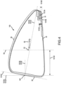
- the club head 100 can be viewed from a front view ( FIG. 2 ) when the strike face 38 is viewed from a direction perpendicular to the x'y' plane 10124. Further, in these or other embodiments, the club head 100 can be viewed from a side view or side cross-sectional view ( FIG. 4 ) when the heel 22 is viewed from a direction perpendicular to the y'z' plane 10128.
- the golf club head 100 further includes a center of gravity or CG 50 (shown in FIGs. 3 , 4 , and 5 ) that defines an origin of a coordinate system including an x-axis 54, a y-axis 58, and a z-axis 62.
- the y-axis 58 (shown in FIGs. 2 and 164) extends through the club head 100 center of gravity 50 from the crown or top 26 to the sole or bottom 30, is parallel to the hosel axis 46 when viewed from the side view, and is positioned at a 30 degree angle from the hosel axis 46 when viewed from a front view ( FIGs. 2 ).
- the x-axis 54 (shown in FIG.
- the club head center of gravity 50 extends through the club head center of gravity 50 from the toe or toe end 18 to the heel or heel end 22, perpendicular to y-axis 58 when viewed from a front view and parallel to the x'y' plane 10124.
- the z-axis 62 (shown in FIGs. 3-5 ) extends through the center of gravity 50 of the club head 100 from the club face 38 to the back end 34 and perpendicular to the x-axis 54 and the y-axis 58.
- the x-axis 54 extends through the head CG 50 from the toe or toe end 18 to the heel or heel end 22 and parallel to the x' axis 10106.
- the y-axis 58 extends through the head CG 50 from the crown or top 26 to the sole or bottom 30 parallel to the y' axis 10104.
- the z-axis 62 extends through the head CG 50 from the club face 38 to the back end 34 and parallel to the z' axis 10108.
- the club head 100 further comprises a head depth plane 10120 and a head depth axis 10122, wherein the head depth plane 10120 extends through the geometric center 140 of the strike face 38, perpendicular to the loft plane 10102, in a direction from the heel 22 to the toe 18 of the club head 100, and the head depth axis 10122 extends through the geometric center 140 of the strike face 38, perpendicular to the loft plane 10102.
- the head CG 50 is located at a head CG depth 10130 from the x'y' plane 10124, measured in a direction perpendicular to the x'y' plane 10124.
- the head CG 50 can be located at a head CG depth 10130 from the loft plane 10102, measured in a direction perpendicular to the loft plane 10102.
- the head CG 50 is further located at a head CG height 10132 from the head depth plane 10120, measured in a direction perpendicular to the head depth plane 10120.
- the head CG height 10132 is measured as the offset distance of the head CG 50 from the head depth plane 10120 in a direction perpendicular to the head depth plane 10120 toward the crown 26 or toward the sole 30.
- the x-axis 54 and the z-axis 62 are arranged to coincide with numbers on an analog clock in FIG. 3 .
- the z-axis 62 extends between 12 o'clock ("12" through the club face 38) and 6 o'clock ("6" through the back 34), and the x-axis 54 extends between 3 o'clock ("3" through the toe end 18) and 9 o'clock ("9" through the heel end 22).
- club head moment of inertia results in increased club head forgiveness for off-center hits.
- a club head center of gravity positioned low and back beneficially increases moment of inertia, reduces backspin, and increases launch angle of a golf ball on impact.
- Club head center of gravity adjustability allows for desired trajectory tuning of a club head by an end user.
- the embodiments of the golf club heads described below include adjustable weighting systems while maintaining or preventing a significant reduction in club head moment of inertia, and low and back club head center of gravity positioning.
- many embodiments below describe low profile adjustable weighting systems and/or optimally positioned adjustable weighting systems to maintain a high club head moment of inertia and low and back club head center of gravity position, similar to a club head devoid of an adjustable weighting system, while providing user adjustability of ball flight and/or trajectory.
- Maintaining a high club head moment of inertia about the club head CG results in increased forgiveness for off-center hits, and maintaining a high club head moment if inertia about the hosel axis results in increased rotational stability during a swing.
- maintaining a low and back club head center of gravity beneficially increases club head moment of inertia about the head CG and reduces backspin.
- the club head 100 comprises a moment of inertia about the x-axis I xx (i.e. crown-to-sole moment of inertia), a moment of inertia about the y-axis I yy (i.e. heel-to-toe moment of inertia), and a moment of inertia about the hosel axis 46 I hh .
- the club heads comprising the adjustable weighting systems described herein can have a moment of inertia about the x-axis I xx greater than 3100 g ⁇ cm 2 , greater than 3200 g ⁇ cm 2 , greater than 3300 g ⁇ cm 2 , greater than 3400 g ⁇ cm 2 , greater than 3500 g ⁇ cm 2 , greater than 3600 g ⁇ cm 2 , greater than 3700 g ⁇ cm 2 , greater than 3800 g ⁇ cm 2 , greater than 3900 g ⁇ cm 2 , greater than 4000 g ⁇ cm 2 , greater than 4100 g- cm 2 , greater than 4200 g ⁇ cm 2 , greater than 4300 g ⁇ cm 2 , greater than 4400 g ⁇ cm 2 , or greater than 4500 g ⁇ cm 2 .
- the club heads comprising the adjustable weighting systems described herein have a moment of inertia about the x-axis I xx between 3100 and 4000 g ⁇ cm 2 , between 3100 and 3800 g ⁇ cm 2 , between 3200 and 4000 g ⁇ cm 2 , between 3200 and 4000 g- cm 2 , between 3300 and 4000 g ⁇ cm 2 , between 3400 and 4000 g ⁇ cm 2 , or between 3500 and 4000 g ⁇ cm 2 .
- club heads comprising the adjustable weighting systems described herein can have a moment of inertia about the y-axis I yy greater than 4700 g ⁇ cm 2 , greater than 4800 g ⁇ cm 2 , greater than 4900 g ⁇ cm 2 , greater than 5000 g ⁇ cm 2 , greater than 5100 g ⁇ cm 2 , greater than 5200 g ⁇ cm 2 , greater than 5300 g ⁇ cm 2 , greater than 5400 g ⁇ cm 2 , greater than 5500 g ⁇ cm 2 , greater than 5600 g ⁇ cm 2 , greater than 5700 g ⁇ cm 2 , greater than 5800 g ⁇ cm 2 , greater than 5900 g ⁇ cm 2 , or greater than 6000 g ⁇ cm 2 .
- the club heads comprising the adjustable weighting systems described herein have a moment of inertia about the y-axis I yy between 4800 and 6000 g ⁇ cm 2 , between 4900 and 6000 g ⁇ cm 2 , between 5000 and 6000 g ⁇ cm 2 , between 5100 and 6000 g ⁇ cm 2 , between 5200 and 6000 g ⁇ cm 2 , between 5300 and 6000 g ⁇ cm 2 , or between 5400 and 6000 g ⁇ cm 2 .
- club heads comprising the adjustable weighting systems described herein can have a moment of inertia about the hosel-axis I hh greater than 7500 g ⁇ cm 2 , greater than 8000 g ⁇ cm 2 , greater than 8250 g ⁇ cm 2 , greater than 8500 g ⁇ cm 2 , greater than 8750 g ⁇ cm 2 , greater than 9000 g ⁇ cm 2 , greater than 9050 g ⁇ cm 2 , or greater than 10000 g ⁇ cm 2 .
- the club heads comprising the adjustable weighting systems described herein have a moment of inertia about the hosel-axis I hh between 7500 and 10000 g ⁇ cm 2 , between 8000 and 10000 g ⁇ cm 2 , between 8500 and 10000 g ⁇ cm 2 , or between 9000 and 10000 g ⁇ cm 2 .
- many embodiments of the club heads with adjustable weighting systems comprise a combined moment of inertia about the head CG (MOI CG ) defined as the sum of the moment of inertia about the x-axis and the moment of inertia about the y-axis.
- MOI CG I xx + I yy
- the combined moment of inertia about the head center of gravity MOI CG can be greater than 7600 g ⁇ cm 2 , greater than 7700 g ⁇ cm 2 , greater than 7800 g ⁇ cm 2 , greater than 7900 g ⁇ cm 2 , greater than 8000 g ⁇ cm 2 , greater than 8100 g- cm 2 , greater than 8200 g ⁇ cm 2 , greater than 8300 g ⁇ cm 2 , greater than 8400 g ⁇ cm 2 , greater than 8500 g ⁇ cm 2 , greater than 8600 g ⁇ cm 2 , greater than 8700 g ⁇ cm 2 , greater than 8800 g ⁇ cm 2 , greater than 8900 g ⁇ cm 2 , greater than 9000 g ⁇ cm 2 , greater than 9100 g ⁇ cm 2 , greater than 9200 g ⁇ cm 2 , or greater than 9300 g ⁇ cm 2 .
- the combined moment of inertia about the club head head center of gravity MOI CG can be between 7700 and 9500 g ⁇ cm 2 , between 7800 and 9500 g ⁇ cm 2 , between 7900 and 9500 g ⁇ cm 2 , between 8000 and 9500 g ⁇ cm 2 , between 8100 and 9500 g ⁇ cm 2 , between 8200 and 9500 g ⁇ cm 2 , or between 8300 and 9500 g ⁇ cm 2 .
- many embodiments of the club heads with adjustable weighting systems comprise a combined moment of inertia about the head CG and hosel (MOI CG-H ), defined as the sum of the moment of inertia about the x-axis, the moment of inertia about the y-axis, and the moment of inertia about the hosel axis.
- MOI CG ⁇ H I xx + I yy + I hh
- the combined moment of inertia about the head CG and hosel MOI CG-H can be greater than 14800 g ⁇ cm 2 , greater than 14900 g ⁇ cm 2 , greater than 15000 g ⁇ cm 2 , greater than 15100 g ⁇ cm 2 , greater than 15200 g ⁇ cm 2 , greater than 15300 g ⁇ cm 2 , greater than 15400 g ⁇ cm 2 , greater than 15500 g ⁇ cm 2 , greater than 15600 g ⁇ cm 2 , greater than 15700 g ⁇ cm 2 , greater than 15800 g ⁇ cm 2 , greater than 15900 g ⁇ cm 2 , greater than 16000 g ⁇ cm 2 , greater than 16200 g ⁇ cm 2 , greater than 16400 g ⁇ cm 2 , greater than 16600 g ⁇ cm 2 , greater than 16800 g ⁇ cm 2 , greater than 17000 g ⁇ cm 2 , greater than 17200 g ⁇ cm 2 , greater than 17400 g ⁇ cm 2 , greater than 17600 g ⁇ cm
- the combined moment of inertia about the head CG and hosel MOI CG-H can be between 15000 and 19500 g ⁇ cm 2 , between 15000 and 19000 g ⁇ cm 2 , between 15000 and 18000 g ⁇ cm 2 , between 16000 and 19500 g ⁇ cm 2 , between 16000 and 19000 g ⁇ cm 2 , or between 16000 and 18000 g- cm 2 .
- the combined moment of inertia about the head CG and hosel MOICG-H can be greater than 15000 g ⁇ cm 2 for club heads with adjustable weighting systems having a volume between 425 and 450 cubic centimeters (cc), and the combined moment of inertia about the head CG and hosel MOI CG-H can be greater than 17000 g ⁇ cm 2 for club heads with adjustable weighting systems having a volume between 450 and 500 cubic centimeters (cc).
- the club heads comprising the adjustable weighting systems described herein can have a head CG depth 10130 greater than 1.6 inches, greater than 1.65 inches, greater than 1.7 inches, greater than 1.75 inches, greater than 1.8 inches, greater than 1.85 inches, greater than 1.9 inches, greater than 1.95 inches, or greater than 2.0 inches.
- the club head having the adjustable weighting systems can have a head CG depth 10130 between 1.61 and 2.0 inches, between 1.65 and 2.0 inches, between 1.7 and 2.0 inches, between 1.8 and 2.0 inches, between 1.61 and 3.0 inches, between 1.65 and 3.0 inches, between 1.7 and 3.0 inches, between 1.8 and 3.0 inches, between 1.9 and 3.0 inches, or between 2.0 and 3.0 inches.
- the club heads comprising the adjustable weighting systems described herein can have a head CG height 10132 located below the head depth plane 10120 (i.e. located between the head depth plane 10120 and the sole 30 of the club head). Further, the club heads comprising the adjustable weighting systems described herein can have a head CG height 10132 located within 0.10 inch, within 0.09 inch, within 0.08 inch, within 0.07 inch, within 0.06 inch, within 0.05 inch, or within 0.04 inch of the head depth plane 10120 toward the crown 26 or toward the sole 30 of the club head.
- the adjustable weight system includes one or more weights that are repositionable to a plurality of discrete portions or attachment locations of the club head to adjust the head CG position. Adjusting the head CG position using the adjustable weight systems described herein can affect ball trajectory and/or spin characteristics of the club head at impact, while maintaining a high club head moment of inertia.
- the adjustable weighting system can comprise two or more discrete attachment locations for receiving the one or more weights.
- the adjustable weight system includes two, three, four, or five discrete attachment locations.
- the attachment locations can include a first attachment location positioned toward the back end 34 and the toe 18 and a second attachment location positioned toward the back end 24 and the heel 22 of the club head.
- a distance between the first attachment location and the second attachment location can be greater than 0.8 inch, greater than 0.9 inch, greater than 1.0 inch, greater than 1.1 inches, greater than 1.2 inches, or greater than 1.3 inches.
- the distance between the first attachment location and the second attachment location can be between 0.8-1.3 inches, between 0.9-1.3 inches, between 1.0-1.3 inches, or between 1.1-1.3 inches.
- the attachment locations can include a first attachment location A positioned toward the back end 34 and the toe 18, a second attachment location C positioned toward the back end 34 and the heel 22, and a third attachment location B.
- the third attachment location B can be positioned centrally and toward the back end 34 of the club head, generally aligned with or adjacent to the head depth axis 10122, and/or between the first and second attachment locations A, C.
- a distance between adjacent attachment locations e.g.
- the distance between the first attachment A location and the third attachment location B, or the distance between the second attachment location C and the third attachment location B) can be greater than 0.5 inch, greater than 0.6 inch, greater than 0.7 inch, greater than 0.8 inch, greater than 0.9 inch, or greater than 1.0 inch.
- the distance between adjacent attachment locations e.g. the distance between the first attachment location A and the third attachment location B, or the distance between the second attachment location C and the third attachment location B
- the adjustable weighting system can include any number of discrete attachment locations greater than one, such as, two, three, four, five, six, seven, eight, or more discrete attachment locations.
- a distance between adjacent attachment locations can be greater than 0.4 inch, greater than 0.5 inch, greater than 0.6 inch, greater than 0.7 inch, greater than 0.8 inch, or greater than 0.9 inch.
- the distance between adjacent attachment locations can be between 0.4-0.9 inch, between 0.5-0.9 inch, between 0.6-0.9 inch, or between 0.7-0.9 inch.
- a distance between adjacent attachment locations can be greater than 0.3 inch, greater than 0.4 inch, greater than 0.5 inch, greater than 0.6 inch, greater than 0.7 inch, or greater than 0.8 inch.
- the distance between adjacent attachment locations can be between 0.3-0.8 inch, between 0.4-0.8 inch, between 0.5-0.8 inch, or between 0.6-0.8 inch.
- the plurality of discrete attachment locations of the club heads having adjustable weighting systems described herein can comprise various features including protruding bodies, apertures, recesses or ports capable of receiving a fastener, notches or tabs or cutout regions, ribs or grooves, pegs, hooks, magnets, programmable magnets, or any other suitable attachment means.
- the fastener can comprise the same material as the body, or a material having a lighter density than the body, such that the fastener does not contribute to the adjustable weighting properties of the club head.
- the apertures or recesses or ports can be threaded to receive a threaded fastener.
- the adjustable weighting system is devoid of multiple and/or deep ports or recesses that require significant internal structure required to secure one or more weights within the ports or recesses.
- the adjustable weighting system further comprises one or more weights positionable at the plurality of discrete attachment locations.
- the one or more weights can have a height 10152 measured in a crown to sole direction, parallel to the y-axis 58, when the weight is coupled to one or more of the attachment locations, a width 10154 measured in a heel to toe direction, parallel to the x-axis 54, when the weight is coupled to one or more of the attachment locations, and a depth 10156 measured in a front to back direction, parallel to the z-axis 62, when the weight is coupled to one or more of the attachment locations.
- the height 10152 can be less than 0.5 inch, less than 0.4 inch, less than 0.3 inch, less than 0.25 inch, less than 0.2 inch, less than 0.18 inch, less than 0.16 inch, less than 0.14 inch, less than 0.12 inch, or less than 0.10 inch.
- the width 10154 can be less than 1.3 inches, less than 1.2 inches, less than 1.1 inches, less than 1.0 inch, less than 0.9 inch, less than 0.8 inch, less than 0.7 inch, less than 0.6 inch, less than 0.5 inch, or less than 0.4 inch.
- the depth 10156 can be less than 1.0 inch, less than 0.9 inch, less than 0.8 inch, less than 0.7 inch, less than 0.6 inch, less than 0.5 inch, less than 0.4 inch, less than 0.3 inch, less than 0.2 inch, or less than 0.1 inch.
- one or more of the weights can have a surface area in contact with the club head body when the weight is coupled to any of the attachment.
- the surface area of the weight in contact with the club head can be less than 0.75 inch 2 , less than 0.7 inch 2 , less than 0.65 inch 2 , less than 0.6 inch 2 , less than 0.55 inch 2 , less than 0.5 inch 2 , less than 0.45 inch 2 , less than 0.4 inch 2 , less than 0.35 inch 2 , less than 0.3 inch 2 , or less than 0.25 inch 2 .
- the adjustable weighting system includes a first weight W positionable in the plurality of discrete attachment locations on the club head.
- the adjustable weight system can further comprise additional weights, such as a second weight, a third weight, a fourth weight, and a fifth weight positionable in the plurality of discrete attachment locations on the club head.
- each weight of the plurality of weights can be positioned in a different discrete attachment location on the club head.
- each weight of the plurality of weights can be removed and replaced or repositioned in different discrete attachment locations on the club head. While the embodiments of the adjustable weight system described herein include up to five weights, other embodiments can include adjustable weighting systems having any number of weights.
- the first weight is heavier than the remaining weights (e.g. the second weight, the third weight, the fourth weight, and/or the fifth weight).
- the first weight can comprises a mass greater than 10 grams, greater than 12 grams, greater than 14 grams, greater than 16 grams, greater than 18 grams, greater than 20 grams, greater than 22 grams, greater than 24 grams, greater than 26 grams, greater than 28 grams, or greater than 30 grams.
- first weight can comprises a mass between 6 and 50 grams, between 10 and 50 grams, between 15 and 50 grams, between 20 and 50 grams, between 15 and 40 grams, between 20 and 40 grams, between 25 and 35 grams, between 10 and 25 grams, between 15 and 25 grams, between 10 and 20 grams, or between 15 and 20 grams.
- the remaining weights e.g.
- the second weight, the third weight, the fourth weight, and/or the fifth weight can comprise a mass less than 20 grams, less than 18 grams, less than 16 grams, less than 14 grams, less than 12 grams, less than 10 grams, less than 8 grams, less than 6 grams, less than 4 grams, or less than 2 grams.
- the remaining weights can comprise a mass between 0.10 and 15 grams, between 0.25 and 10 grams, between 0.5 and 7 grams, or between 1 and 10 grams.
- the first weight can be positioned in any of the discrete attachment locations.
- the first weight can be positioned in the first attachment location positioned near the toe 18 or the second attachment location positioned near the heel 22.
- shifting the first weight from the first attachment location to the second attachment location shifts the head CG toward the heel 22, and shifting the first weight from the second attachment location to the first attachment location shifts the head CG toward the toe 18.
- the remaining attachment location can be devoid of a weight, or the remaining attachment location can comprise an additional weight (e.g. the second weight).
- the first weight W can be positioned in the third attachment location B positioned centrally, thereby generating a neutral head CG position.
- the first weight can be shifted from the third attachment location B to the first attachment location A, positioned toward the toe 18, thereby shifting the head CG 50 toward the toe 18 by a distance.
- the first weight W can be shifted from the third attachment location B to the second attachment location C, positioned toward the heel 22, thereby shifting the head CG 50 toward the heel 22 by a distance.
- the remaining locations can be devoid of weights, or the remaining locations can comprise additional weights (e.g. the second weight and/or the third weight).
- Shifting the first weight W from an attachment location nearest the toe 18 to an attachment location nearest the heel 22 can shift the head CG 50 by a distance of at least 0.10 inch, at least 0.15 inch, at least 0.20 inch, at least 0.25 inch, or at least 0.30 inch, in a direction extending parallel to the x-axis 54.
- shifting the first weight W from an attachment location nearest the toe 18 to an attachment location nearest the heel 22 can shift the head CG 50 by a distance between 0.10 and 0.30 inch, between 0.15 and 0.30 inch, between 0.20 and 0.30 inch, between 0.15 and 0.25 inch, or between 0.20 and 0.25 inch.
- shifting the head CG 50 toward the toe 18 can generate a fade or correct for a hook. Conversely, shifting the head CG 50 toward the heel 22 can generate a draw or correct for a slice. In the embodiments of the adjustable weighting system described below, shifting head CG 50 in a direction extending parallel to the x-axis 54 between 0.10 and 0.30 inch can result in a change in shot bend of 4.6 to 13.9 yards.
- Other embodiments can include one or more discrete attachment locations positioned toward the strike face 38 of the club head 100.
- shifting one or more weights to an attachment location(s) near the back end 34 of the club head 100 from an attachment location near the strike face 38 can increase the club head moment of inertia about the head CG MOI CG and increase dynamic loft or launch angle of a golf ball.
- shifting one or more weights to an attachment location(s) near the strike face 38 of the club head 100 from an attachment location near the back end 34 can reduce dynamic loft or launch angle of a golf ball.
- the embodiments of the club heads having adjustable weighting systems described herein maximize head CG depth 10130 and club head moment of inertia (or minimize the reduction in head CG depth 10130 and club head moment of inertia typically associated with introducing adjustability compared to a non-adjustable club head).
- the maximized head CG depth and club head moment of inertia are achieved with first adjustable weight having a relatively low mass, thereby increasing the efficiency of the design to maintain club head performance characteristics (e.g. forgiveness, low back spin, high launch), while enabling user adjustability of ball spin and/or trajectory.
- the club heads having adjustable weighting systems comprise a depth to mass ratio of the head CG depth 10130 to the mass of the first weight W m .
- the depth to mass ratio of the club head can be greater than 0.060 inch/gram, greater than 0.070 inch/gram, greater than 0.080 inch/gram, greater than 0.090 inch/gram, greater than 0.100 inch/gram, greater than 0.110 inch/gram, greater than 0.120 inch/gram, or greater than 0.130 inch/gram.
- the depth to mass ratio can be between 0.070 and 0.13 inch/gram, between 0.080 and 0.13 inch/gram, between 0.090 and 0.13 inch/gram, between 0.070 and 0.11 inch/gram, between 0.080 and 0.11 inch/gram, or between 0.090 and 0.11 inch/gram.
- the mass of the first weight can be less than 25 grams, less than 24 grams, less than 23 grams, less than 22 grams, less than 20 grams, less than 19 grams, less than 18 grams, less than 17 grams, less than 16 grams, or less than 15 grams.
- the mass of the first weight can be between 10 and 20 grams, between 12 and 20 grams, between 14 and 20 grams, between 16 and 20 grams, between 10 and 18 grams, between 12 and 18 grams, or between 14 and 18 grams.
- Depth to Mass Ratio Head CG Depth / W m
- the club heads having adjustable weighting systems can comprise a first inertia to mass ratio defined as the combined moment of inertia about the head CG MOI CG to the mass of the first weight W m .
- the first inertia to mass ratio can be greater than 400 cm 2 , greater than 410 cm 2 , greater than 420 cm 2 , greater than 430 cm 2 , greater than 440 cm 2 , greater than 450 cm 2 , greater than 460 cm 2 , greater than 470 cm 2 , greater than 480 cm 2 , greater than 490 cm 2 , greater than 500 cm 2 , greater than 510 cm 2 , greater than 520 cm 2 , greater than 530 cm 2 , greater than 540 cm 2 , or greater than 550 cm 2 .
- the first inertia to mass ratio can be between 400 and 550 cm 2 , between 410 and 550 cm 2 , between 420 and 550 cm 2 , between 430 and 550 cm 2 , between 440 and 550 cm 2 , between 450 and 550 cm 2 , between 400 and 500 cm 2 , between 410 and 500 cm 2 , between 420 and 500 cm 2 , between 430 and 500 cm 2 , between 440 and 500 cm 2 , or between 450 and 500 cm 2 .
- the mass of the first weight can be less than 25 grams, less than 24 grams, less than 23 grams, less than 22 grams, less than 20 grams, less than 19 grams, less than 18 grams, less than 17 grams, less than 16 grams, or less than 15 grams. In some embodiments, the mass of the first weight can be between 10 and 20 grams, between 12 and 20 grams, between 14 and 20 grams, between 16 and 20 grams, between 10 and 18 grams, between 12 and 18 grams, or between 14 and 18 grams.
- First Inertia to Mass Ratio MOICG/W m
- the embodiments of the club heads having adjustable weighting systems described herein maximize the total shift in head CG as achievable by adjusting the one or more weights to the plurality of discrete attachment locations.
- the maximized total shift in head CG is achieved with first adjustable weight having a relatively low mass, thereby increasing the efficiency of the design to maintain club head performance characteristics (e.g. forgiveness, low back spin, high launch) while enabling user adjustability of ball spin and/or trajectory.
- the club heads having adjustable weighting systems comprise a head CG to mass ratio defined as the total shift in head CG or maximum head CG shift to the mass of the first weight.
- the head CG to mass ratio can be greater than 0.008 inch/gram, greater than 0.009 inch/gram, greater than 0.010 inch/gram, greater than 0.011 inch/gram, greater than 0.012 inch/gram, greater than 0.013 inch/gram, greater than 0.014 inch/gram, or greater than 0.015 inch/gram.
- the head CG to mass ratio can be between 0.008 and 0.015 inch/gram, between 0.009 and 0.015 inch/gram, between 0.010 and 0.015 inch/gram, between 0.008 and 0.013 inch/gram, between 0.009 and 0.013 inch/gram, or between 0.010 and 0.013 inch/gram.
- the mass of the first weight can be less than 25 grams, less than 24 grams, less than 23 grams, less than 22 grams, less than 20 grams, less than 19 grams, less than 18 grams, less than 17 grams, less than 16 grams, or less than 15 grams.
- the mass of the first weight can be between 10 and 20 grams, between 12 and 20 grams, between 14 and 20 grams, between 16 and 20 grams, between 10 and 18 grams, between 12 and 18 grams, or between 14 and 18 grams.
- Head CG to Mass Ratio Maximum Head CG Shift/W m
- the one or more weights of the adjustable weighting system comprise a weight CG 10134.
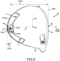
- the weight CG is positioned near a rear perimeter or skirt 10136 of the club head when viewed from a top or bottom view ( FIG. 5 ), and at a maximized distance 10138 from the geometric center 140 of the strike face 38.
- Positioning the weight CG 10134 near the rear perimeter 10136 of the club head 100 or away from the strike face 38 can increase perimeter weighting and club head moment of inertia, thereby resulting in increased club head forgiveness for off center hits, compared to adjustable weights positioned closer to the strike face.
- weight CG 10134 near the rear perimeter 10136 or away from the strike face 38 can result in a head CG position that is lower and farther back, thereby increasing club head moment of inertia and reducing back spin, back compared to adjustable weights positioned closer to the strike face.
- the weight CG 10134 of one or more of the weights is positioned at a distance 10142 from the rear perimeter 10136 of the club head 100 when the weight is positioned at one or more of the plurality of discrete attachment locations on the club head 100.
- the distance 10142 can be measured as the projected distance from the weight CG to the perimeter 10136 when the club head is viewed from a bottom view, perpendicular to the x'z' plane 10126, when the weight is positioned at one or more of the plurality of discrete attachment locations on the club head 100. Further, the distance 10142 can be measured in a direction parallel to the x'z' plane 10126, when the weight is positioned at one or more of the plurality of discrete attachment locations on the club head 100.
- the weight CG 10134 of one or more of the weights can be positioned within 0.7 inch, within 0.65 inch, within 0.6 inch, within 0.55 inch, within 0.5 inch, within 0.45 inch, within 0.4 inch, within 0.35 inch, within 0.3 inch, within 0.25 inch, or within 0.2 inch of the rear perimeter 10136 of the club head 100.
- the weight CG 10134 of one or more of the weights can be positioned between 0.10 and 0.50 inch, between 0.25 and 0.5 inch, between 0.10 and 0.25 inch, between 0.10 and 0.35 inch, or between 0.10 and 0.45 inch from the rear perimeter 10136 of the club head 100.
- the weight CG 10134 of one or more of the weights is positioned at a distance 10138 from the geometric center 140 of the strike face 38 of the club head 100 when the weight is positioned at one or more of the plurality of discrete attachment locations on the club head 100.
- the weight CG 10134 of one or more of the weights can be positioned at a distance 10138 greater than 2.0 inches, greater than 2.25 inches, greater than 2.5 inches, greater than 2.75 inches, greater than 3.0 inches, greater than 3.25 inches, greater than 3.5 inches, or greater than 3.75 inches from the geometric center of the strike face.
- the weight CG 10134 of one or more of the weights can be positioned at a distance 10138 between 2.0 and 3.5 inches, between 2.5 and 3.5 inches, between 2.0 and 3.0 inches, between 2.5 and 3.0 inches, between 2.5 and 4.0 inches, between 3.0 and 3.75 inches, between 3.0 and 4.0 inches, between 3.2 and 4.0 inches, or between 3.5 and 4.0 inches from the geometric center 140 of the strike face 38. Positioning the weight CG 10134 away from the geometric center 140 of the strike face 38 can increase perimeter weighting and club head moment of inertia, thereby resulting in increased club head forgiveness for off center hits, compared to adjustable weights positioned closer to the strike face.
- weight CG 10134 away from the geometric center 140 of the strike face 38 can result in a head CG position that is lower and farther, thereby increasing club head moment of inertia and reducing back spin, back compared to adjustable weights positioned closer to the strike face.
- the weight CG 10134 protrudes from an external contour or outer surface 10146 of the sole 30, is positioned flush with the external contour 10146 of the sole 30, and/or is positioned minimally inset relative to the external contour 10146 of the sole 30. Positioning the weight CG 10134 minimally inset, flush with, or external relative to the external contour 10146 of the sole 30 requires less structural support material to receive the one or more weights, thereby maintaining a low profile adjustable weighting system.
- positioning the weight CG 10134 minimally inset, flush with, or external relative to the external contour 10146 of the sole 30 can increase perimeter weighting and club head moment of inertia, thereby resulting in increased club head forgiveness for off center hits, compared to internal adjustable weights or adjustable weights recessed into the club head. Further, positioning the weight CG 10134 minimally inset, flush with, or external relative to the external contour 10146 of the sole 30 can result in a head CG position that is lower and farther back, thereby increasing club head moment of inertia and reducing back spin, back compared to internal adjustable weights or adjustable weights recessed into the club head.
- the weight CG 10134 of one or more of the weights is positioned at a distance 10148 from the external contour 10146 of the sole 30 when the weight is positioned at one or more of the plurality of discrete attachment locations on the club head 100, wherein the distance 10148 is measured in a direction parallel to the y-axis 58.
- the weight CG 10134 of one or more of the weights can protrude from the external contour 10146 of the sole by up to 0.10 inch, up to 0.15 inch, up to 0.20 inch, up to 0.25 inch, or up to 0.30 inch.
- the weight CG 10134 of the one or more weights protrudes from the external contour 10146 of the sole 30 by 0.10 to 0.25 inch, by 0.15 to 0.25 inch, by 0.15 to 0.25 inch, or by 0.15 to 0.30 inch.
- the weight CG 10134 can be inset relative to the external contour 10146 of the sole 30 by a distance 10148 of less than 0.15 inch, less than 0.14 inch, less than 0.13 inch, less than 0.125 inch, less than 0.12 inch, less than 0.11 inch, less than 0.10 inch, less than 0.09 inch, less than 0.08 inch, or less than 0.07 inch.
- the weight CG 10134 of the one or more weights is inset relative to the external contour 10148 of the sole 30 by a distance 10148 between 0.05 and 0.15 inch, between 0.05 and 0.125 inch, between 0.05 and 0.15 inch, between 0.10 and 0.15 inch, between 0.10 and 0.125 inch, or between 0.10 and 0.15 inch.
- FIGS. 6 and 7 illustrate a club head 11010 similar to club head 100 described above.
- the club head 11010 having a club head body 11014 includes an adjustable weighting system 11066 located on a sole 11030 that is adjustable by an end user to modify the club head 11010 center of gravity and/or moment of inertia and/or heel/toe bias to achieve desired performance characteristics (e.g., forgiveness, spin, trajectory) under various circumstances.
- the club head 11010 can be similar in many respects to club head 100, with similar or identical numbers referencing similar or identical components.
- the adjustable weighting system 11066 is a low profile system and thereby does not significantly shift or change the MOI of the club head 11010 when compared to a club head devoid of the adjustable weighting system 11066.
- the low profile adjustable weighting system 11066 ensures that shifts in the club head 11010 CG occur mainly in a heel end 11022 to toe end 11018 direction keeping the overall CG of the club head 11010 in a low and back location.
- the center of gravity position and MOI of club head 11010 can be similar or identical to the center of gravity position and MOI of club head 100 described above.
- the adjustable weighting system 11066 can comprise a recessed portion 11080.
- the recessed portion 11080 comprises a recessed surface 11081 configured to include a plurality of discrete attachment locations.
- the plurality of discrete attachment locations can comprise various features including protruding bodies, apertures, recesses or ports capable of receiving a fastener, notches or tabs or cutout regions, ribs or grooves, pegs, hooks, magnets, programmable magnets, or any other suitable attachment means.
- the adjustable weighting system 11066 includes a recessed surface 11081 comprising three discrete attachment locations 11070A, 11070B, and 11070C.
- the three discrete attachment locations comprise feature 11070A, 11070B, and 11070C.
- the features 11070A, 11070B, and 11070C can comprise any of the features discussed above.
- the attachment locations and corresponding features 11070A, 11070B, and 11070C are configured to receive one or more weights 11082.
- the recessed portion 11080 defines a groove, channel, and/or recessed track that extends along the sole or bottom 11030 of the club head 11010, adjacent a trailing edge 11072 or a rear perimeter 10136, and extends generally in an arcuate configuration from the toe or toe end 11018 to the heel or heel end 11020.
- the recessed portion 11080 generally follows the contour of the trailing edge 11072, wherein the recessed portion 11080 can be slightly offset from the trailing edge 11072 or rear perimeter 10136 between the heel end 11022 and the toe end 11018.
- the recessed portion 11080 comprises a recessed surface 11081 being offset from the sole 11030 of the club head 11010 by a first wall 11083.
- a portion of the recessed surface 11081 can further be offset from the sole 11030 by a second wall 11084, wherein the second wall 11084 is opposite the first wall 11083, proximate to the trailing edge 11072 or rear perimeter 10136.
- the recessed surface 11081 extends substantially parallel to the sole 11030 of the club head 11010, while the first and second walls 11083, and 11084 generally extend substantially perpendicular to the recessed surface 11081 and/or the sole 11030.
- the first wall 11083 and the second wall 11084 can extend at a non-perpendicular angle between the recessed surface 11081 and the sole 11030.
- the recessed portion 11081 includes a depth measured as the distance from the recessed surface 11081 to the sole 11030 in a direction parallel to the recessed surface 11081.
- the recessed portion 11080 has a varying depth such that it is deeper in some areas than in other areas (e.g., may have a continuously or intermittently changing depth).
- the recessed portion 11080 can have an increasing, decreasing and/or constant depth along its length from the toe end 11018 to the heel end 11022.
- the weight 11082 may be concealed by the wall 11083 and flush with the sole 11030.
- the recessed portion 11080 comprises a first region 11077 at a toe end 11018 of the club head 110 10, a second region 11076 at the heel end 11022 of the club head 11010, and a third region 11078 disposed between the heel end 11022 and the toe end 11022 along or near the back end 11034.
- the depth at the first region 11077 (and similarly the depth at the second region 11076) of the recessed portion 11080 is less than the depth at the third region.
- the depth of the recessed portion 11080 increases from the first and second regions 11077, 11076 toward the third region 11078, such that the third region 11078 has a constant larger depth than the first and second regions 11077, 11076.
- the weight 11082 can be concealed by the first wall 11083 (e.g., as viewed along the y-axis 58 in FIG. 2 ) when the weight 11082 is coupled to the third region 11078, and the weight 11082 can be at least partially exposed or can at least partially protrude from the contour of the sole 11030 in the first and second regions 11077, 11076.
- the first region 11077, the second region 11076, and the third region 11078 can have a constant depth, such that the weight 11072 is concealed by the wall 11083 when the weight 11082 is coupled to any of the first, second and/or third regions 11077, 11076, 11078.
- the recessed portion 11080 includes other numbers and locations of regions than that illustrated.
- the recessed portion 11080 can include more than one region where the weight 11082 is concealed when coupled.
- the recessed portion 11080 can comprise 1 region, 2 regions, 3 regions, 4 regions, 5 regions, 6 regions, 7 regions, or 8 regions.
- the recessed portion 11080 has a shallow depth ensuring the adjustable weight system 11066 remains low profile.
- the recessed portion 11080 has a maximum depth of 0.25 inches.
- the recessed portion 11080 can have a maximum depth of 1.5, 1.25, 1.0, 0.9, 0.8, 0.7, 0.6, 0.5, 0.4, 0.3, 0.2, or 0.1 inches.
- the depth of the recessed portion 11080 can vary within the range of 0.05 to 0.25, 0.1 to 0.4, 0.1 to 0.6, 0.1 to 0.8, 0.2 to 0.4, 0.2 to 0.6, 0.2 to 0.8, 0.3 to 0.7, 0.3 to 0.9, 0.4 to 0.8, 0.4 to 1.2, 0.5 to 1.0, 0.5 to 1.5, or 1.0 to 1.5 inches.
- the recessed portion 11080 includes a width measured as the distance between the first wall 11083 and the trailing edge 11072 or second wall 11084. In the illustrated embodiments, the recessed portion 11080 includes a varying width.
- the first region 11077 has an increasing width from the toe end 11018 towards the center or third region 11078
- the second region 11076 comprises an increasing width from the heel end 11022 towards the center and or third region 11078
- the third region 11078 comprises a constant width which is smaller than the average width of the first and or second regions 11077, 11076.
- the width of the recessed portion 11080 can increase from the center or third region 11078 toward the first region 11077, and toward the second region 11076.
- the recessed portion 11080 can have an increasing, decreasing and/or constant width. In many embodiments, the width can be less than 2.0 inches.
- the width can be less than 2.0, 1.75, 1.5, 1.25, 1.0, 0.9, 0.8, 0.7, 0.6, 0.5, 0.4, 0.3, or 0.2 inches. In other embodiments, the width can vary between 0.1 to 0.5, 0.3 to 0.7, 0.5 to 0.9, 0.7 to 1.1, 0.9 to 1.3, 1.1 to 1.5, 1.3 to 1.7, or 1.5 to 2.0 inches.
- the recessed portion 11080 can include one or more features 11070 defining one or more discrete attachment locations for securing a weight 11082 to the club head 11010.
- the club head 11010 having one or more discrete attachment locations is different than other adjustable weighting systems, wherein the weight can be coupled at any, or at an infinite, or at an unlimited number of locations on the club head.
- the recessed portion 11080 can include three features or attachment locations 11070A, B, C.
- the features 11070A, B, C are shown as apertures configured to receive a screw fastener 11085.
- the screw fastener 11085 can be comprised of a material having a density which is the same or less than the density of the club head 11010.
- the features 11070A, B, C can be a protruding body, aperture, recess, ports capable of receiving a fastener, notches, tabs, cutout regions, ribs, grooves, pegs, hooks, magnets, programmable magnets or any other suitable attachment means.
- the recessed portion 11080 can comprise one, two, three, four, five, six, seven, eight, nine or ten features 11070.
- the features 11070A, B, C are disposed within the recessed portion 11080 along the recessed surface 11081 such that one or more weights 11082 may be releasably or removably coupled to the club head 11010 along the recessed portion 11080. More specifically, a first feature 1 1070A is positioned along the first region 11077 of the recessed portion 11080 near the toe end 11018, a second feature 11070C is positioned along the second region 11076 of the recessed portion near the heel end 11022, and a third feature 11070B is positioned along a third region 11078 of the recessed portion 11080 between the toe and heel end 11018, 11022. In some embodiments, one or more of the features 11070A, B, C can be positioned on the first wall 11083, second wall 11084, and/or the recessed surface 11081 of the recessed portion 11080.
- the weights 11082 can have a generally trapezoidal shape. In other embodiments, the weights 11082 can have a circular, ovular, triangular, trapezoidal, polygonal or any other suitable shape configured to fit within the recessed portion 11080.
- the adjustable weighting system 11066 comprises one weight 11082 capable of removably coupling to the features 11070A, B, C. In other embodiments, the adjustable weighting system 11066 can comprise any number of weights 11082 corresponding with the number of features 11070A, B, C. In other embodiments, the adjustable weighting system 11066 can comprise more or less weights 11082 than the number of features 11070A, B, C. For example, the adjustable weighting system 11066 can comprise one, two, three, four, five, six, seven, eight, nine, or ten weights 11082.
- the weights 11082 comprise apertures extending entirely through the weight 11082 that are sized and configured to receive a threaded fastener or screw fastener 11085.
- the screw fastener 11085 can be threaded through the weight 11082 into the corresponding feature 11070A, B, C, thus securing the weight 11082 to the recessed portion 11080.
- the weight 11082 can comprise a recessed or inset portion for receiving the top portion of the screw fastener 11085, and therefore the screw fastener 11085 can sit flush with an outer portion of the weight 11082.
- the weights 11082 can be configured to be couple to the features 11070 A, B, C through a friction fit, a snap-fit mechanism, with a set-screw, or with any other suitable structure.
- each of the weights 11082 can have the same shape and size.
- the weights 11082 can vary in shape and size, resulting in weights 11082 having varying masses.
- the weights 11082 can comprise different materials such that they vary in mass.
- one weight 11082 can comprise a high density material, such as tungsten, and the remaining weights 11082 can comprise a less dense material, such as polyurethane or another plastic.
- the weights 11082 can comprise the same or different material and can have different sizes or volumes such that they vary in mass. For example, one weight 11082 can have a greater volume than the remaining weights 11082.
- each of the weights 11082 can vary in volume from one another and thus vary in mass. In some embodiments, the weights 11082 can vary in both volume and material from one another. In some embodiments, one of the structures labeled as 11082 is not a weight, but rather a light-weight (e.g., light-weight plastic) cover that snap-fits or otherwise couples to one of the features 1 1070A, B, C.
- a light-weight e.g., light-weight plastic
- the weights 11082 can vary between 0.1-50g.
- one or more of the weights 82 can vary between 0-10g, one or more of the weights 11082 can vary between 10-20g, one or more of the weights 11082 can vary between 20-30, one or more of the weights 11082 can vary between 30-40g, and one or more of the weights 11082 can vary between 40-50g.
- a first weight 11082 can vary between 0-10g
- a second weight 11082 can vary between 10-20g
- a third weight 11082 can vary between 20-30g.
- a first weight 11082 can vary between 1-5g, and a second and third weight 11082 can vary between 5-30g. In other embodiments, a first weight 11082 can vary between 40-50 g, a second weight 11082 can vary between 30-40 g, and a third weight can vary between 20-30 g. In other embodiments, a first and second weight 11082 can vary between 1-10g, and a third 11082can vary between 5-25g. In some embodiments, a first weight 11082 has a mass of 8.5 grams, and a second and third weight 11082 each have a mass of 1.5 grams. In other embodiments, a first weight 11082 has a mass of 12 grams, and a second and third weight 11082 each have a mass of 1.5 grams.
- a first weight 11082 has a mass of 8.5 grams, and a second and third weight 11082 each have a mass of 0.75 grams.
- a first weight can have a mass of 10-20g, 10- 25g, or 15-25g, and the remaining weight (e.g. second, third, fourth, fifth weight) can have a mass of 0.25-2.5g, 0.25-5g, 0.25-7.5g, or 0.25 to 10g.
- the first weight can have a mass of 10, 11, 12, 13, 14, 15, 16, 17, 18, 19, 20, 21, 22, 23, 24, 25, 26, 27, 28, 29 or 30 grams and the remaining weights can have a mass of 1, 2, 3, 4, 5, 6, 7, 8, 9, or 10 grams.
- any number of weights may have the same mass or may have a varying mass between 0.1-50g.
- one of the features 11070A, B, C can receive a weight 11082, while the remaining features 11070A, B, C can be bare and uncovered, devoid of a weight, or can be covered with another material or structure.
- each of the features 11070A, B, C can receive a weight 11082.
- one or more of the features 11070A, B, C can receive a weight 11082.
- one or more of the features 11070A, B, C do not extend past an outer profile of the club head 11010, such that even if the feature 11070A, B, C is left bare and uncovered, the features 11070A, B, C, and or recessed portion 11080 will not interfere with, or disrupt a golfer's swing.
- the weights 11082 may be strategically positioned on the features 11070A, B, C to achieve a desired club head 11010 center of gravity position and/or moment of inertia and/or heel/toe bias.
- a heavier weight 11082 is positioned on the feature 11070B, located between the toe end 11018 and the heel end 11022, while lighter weights are positioned on the features 11070A, and C at the toe end 11018 and the heel end 11022.
- the aforementioned weight 11082 positions results in the center of gravity remaining centered while being shifted towards the back end 11034 of the club head 11010.
- a heavier weight 11082 can be positioned on the feature 11070C at the heel end 11022, while lighter weights 11082 are positioned on the feature 6270A, and B near the toe end 11018 and at the center located between the toe end 6318 and the heel end 6322.
- the aforementioned weight 11082 positions results in the center of gravity being shifted towards the heel end 11022 of the club head 11010.
- a heavier weight 11082 is positioned on the feature 11070A at the toe or toe end 11018, while lighter weights 11082 are positioned on the features 6270C at the heel end 11022 and on the feature 11070B that is located between the toe end 11018 and the heel end 11022.
- one or more of the features 11070A, B, C can be of equal size and shape, such that one weight may be interchangeably used with each of the features 11070A, B, C.
- one or more of the features 1 1070A, B, C can have a differing size and shape, such that each features 11070A, B, C can have its own corresponding weight 11082 or set of weights 11082. Further, adjustment of the position of the weights 11082 on the features 11070 A, B, C can also effect the spin imparted on the ball after impact.
- club head 11010 can further comprise contoured recesses 11031 located on the sole 11030.
- the contour recesses 11031 can comprise a higher elevation (i.e., less depth) than the recessed portion 11080 having the plurality of discrete attachment locations.
- the contoured recesses 11031 extend from the recessed portion 11080 toward the strike face 38 of the golf club head 11010.
- the adjustable weighting system 11066 of golf club head 11010 maintains or prevents a significant reduction in club head moment of inertia, and low and back club head center of gravity positioning, compared to a club head devoid of an adjustable weighting system.
- the adjustable weighting system 11066 of golf club head 11010 maintains a high club head moment of inertia and a low and back club head CG position due to the low profile of the weighting system and the perimeter positioning of the one or more weights.
- the club head 11010 having the adjustable weighting system 11066 can have similar or identical parameters and measurements as club head 100 described above.
- FIGS. 9 and 10 illustrate a club head 12010 similar to club head 100 described above.
- Club head 12010 having a club head body 12014 includes an adjustable weighting system 12066 that is adjustable by an end user to modify the club head 12010 center of gravity and/or moment of inertia and/or heel/toe bias to achieve desired performance characteristics (e.g., forgiveness, spin, trajectory) under various circumstances.
- the club head 12010 can be similar in many respects to club head 100 and 11010, with similar or identical numbers referencing similar or identical components.
- the adjustable weighting system 12066 is a low profile system and thereby does not significantly shift or change the MOI of the club head 12010 when compared to a club head devoid of the adjustable weighting system 12066.
- the low profile adjustable weighting system 12066 ensures that shifts in the club head 12010 CG occur mainly in a heel end 12022 to toe end 12018 direction keeping the overall CG of the club head 12010 in a low and back location.
- the center of gravity position and MOI of club head 12010 can be similar or identical to the center of gravity position and MOI of club head 100 and 11010 described above.
- the adjustable weighting system 12066 can comprise a channel or recessed portion 12013 positioned on the sole 12030 or in the trailing edge 12072 of the club head 12010.
- the recessed portion 12013 can comprise a plurality of discrete attachment locations.
- the plurality of discrete attachment locations can comprise various features including protruding bodies, apertures, recesses or ports capable of receiving a fastener, notches or tabs or cutout regions, ribs or grooves, pegs, hooks, magnets, programmable magnets, or any other suitable attachment means.
- the adjustable weighting system 12066 includes three discrete attachment locations.
- the three discrete attachment locations comprise features 12070A, 12070B, and 12070C.
- the features 12070A, 12070B, and 12070C can comprise any of the features discussed above.
- the attachment locations and corresponding features 12070A, 12070B, and 12070C are configured to receive one or more weights 12082.
- the recessed portion 12080 defines a groove, channel, and/or recessed track that extends within and along the skirt or trailing edge 12072 or rear perimeter 10136, and extends generally in an arcuate configuration from the toe or toe end 12018 to the heel or heel end 12020.
- the channel 12013 is defined by a first surface 12073 ( FIG. 9 ), a second surface 12074 ( FIGS. 9 and 10 ) disposed opposite the first surface 12073, and a third surface 12075 ( FIGS. 9 and 10 ) that extends perpendicular between the first surface 12073 and the second surface 12074.
- the first surface 12073 comprises an upper wall of the channel 12013
- the second surface 12074 comprises a lower wall of the channel 12013
- the third surface 12075 comprises a base or bottom wall of the channel 12013.
- the first surface 12073 extends parallel to the second surface 12074, and perpendicular to the third surface 12075.
- the first and second surfaces 12073, 12074 of the recessed portion 12080 extend in a direction generally perpendicular to the loft plane of the club head 12010
- the third surface 12075 of the recessed portion 12080 extends in a direction generally parallel to the loft plane of the club head 12010.
- the channel 12013 is further defined in part by additional end surfaces 12079 that directly intersect the first surface 12073, the second surface 12074, and the third surface 12075.
- the end surfaces 12079 can provide added support and/or provide an abutment region or edge against which the weights 12082 may rest.
- the end surfaces 12079 can also allow the weights 12082 to appear flush with an outer surface 12090 of the club head. The flush surfaces may improve air flow characteristics during a swing to improve the club head 12010 aerodynamics.
- the channel 12013 includes a depth measured from the third surface 12075 to the sole 12030 in a direction perpendicular to the third surface 12075.
- the channel 12013 can have a varying depth such that it is deeper in some areas than in other areas (e.g., may have a continuously or intermittently changing depth).
- the depth of the channel 12013 can have an increasing, decreasing and/or constant depth along its length from the toe end 12018 to the heel end 12022.
- the weight 12082 When the weight 12082 is coupled to the club head 12010 in a different region of the channel 12013, a portion of the weight 12082 can protrude beyond the first and/or second surfaces 12073, 12074. In other embodiments, the weight 12082 can be recessed within the channel 12013, sit flush within the channel 12013, or protrude beyond the channel 12013 in any position.
- the channel 12013 can comprise a first region 12077 at a toe end 12018 of the club head 12010, a second region 12076 at a heel end 12022 of the club head 12010, and a third region 12078 disposed between the heel or heel end 12022 and the toe or toe end 12018, along a rear or back end 12034.
- the first region 12077, second region 12076 and third region 12078 can be parallel to the contour of the trailing edge 12072.
- any of the first, second, and/or third region 12077, 12076, and/or 12078 can be parallel and/or angled relative to the contour of the trailing edge 12072. In one example as illustrated in FIG.
- the first region 12077, and the second region 12076 can be angled upward toward the trailing edge 12072, extending toward the third region 12078; while the third region is parallel with the contour of the trailing edge 12072.
- the transition between the first region 12077, third region 12078, and second region 12076 can be smooth and devoid of hard edges
- the first region 12077 (and similarly the second region 12076) of the channel 12013 can have a shallow depth, such that a portion of the weight 12082 protrudes out past the first surface 12073 and the second surface 12074 when the weight 12082 is coupled to the first region 12077.
- the weight 12082 can appear flush to the rest of the sole 12030, toe end 12018, or heel end 12022 of the club head 12010.
- the third region 12078 can have a larger depth, such that the weight 12082 is concealed by the first surface 12073 and the second surface 12074 (e.g., as viewed along the y-axis 58 in FIG. 2 ) when the weight 12082 is coupled to the third region 12078.
- the depth of the first, second, and third regions 12077, 12076, and 12078 can comprise the same depth. Further, the transition regions between the first and third regions 12077, and 1278, and the second and third regions 12076, and 12078 can be more shallow than the depth of the first, second, and third regions 12077, 12076, and 12078.
- the channel 12013 can include other numbers and locations of regions than those illustrated. For example, in some embodiments, the channel 12013 can include more than one region where the weight 12082 is concealed when coupled. In some embodiments, the channel 12013 can include a region or regions at the heel end 12022 and/or the toe end 12018 where the weight 12082 is concealed when coupled. In some embodiments, the channel 12013 includes a region or regions at the rear or back end 12034 where a portion of the weight 12082 protrudes beyond the first surface 12073 and/or the second surface 12074 when coupled.
- the channel 12013 has a shallow depth ensuring the adjustable weight system 12066 remains low profile.
- the channel 12013 has a maximum depth of 0.25 inches.
- the channel 12013 can have a maximum depth of 1.5, 1.25, 1.0, 0.9, 0.8, 0.7, 0.6, 0.5, 0.4, 0.3, 0.2, or 0.1 inches.
- the depth of the channel 12013 can vary within the range of 0.05 to 0.25, 0.1 to 0.4, 0.1 to 0.6, 0.1 to 0.8, 0.2 to 0.4, 0.2 to 0.6, 0.2 to 0.8, 0.3 to 0.7, 0.3 to 0.9, 0.4 to 0.8, 0.4 to 1.2, 0.5 to 1.0, 0.5 to 1.5, or 1.0 to 1.5 inches.
- the channel 12013 includes a width measured as the distance between the first surface 12073 and the second surface 12074. In the illustrated embodiments, the channel 12013 includes a constant width. In other embodiments, the channel 12013 can have an increasing, decreasing and/or constant width. In many embodiments, the width can be less than 2.0 inches.
- the width can be less than 2.0, 1.75, 1.5, 1.25, 1.0, 0.9, 0.8, 0.7, 0.6, 0.5, 0.4, 0.3, or 0.2 inches. In other embodiments, the width can vary between 0.1 to 2.0, 0.1 to 0.5, 0.3 to 0.7, 0.5 to 0.9, 0.7 to 1.1, 0.9 to 1.3, 1.1 to 1.5, 1.3 to 1.7, or 1.5 to 2.0 inches.
- the channel 12013 can include one or more features 12070A, B, C defining one or more discrete attachment locations for securing a weight 12082 to the club head 12010.
- the club head 12010 having one or more discrete attachment locations is different than other adjustable weighting systems, wherein the weight can be coupled at any location, or at an infinite, or at an unlimited number of locations on the club head.
- the adjustable weighting system 12066 can comprise 3 features 12070A, B, C.
- the features 12070A, B, C can be one of a protruding body, aperture, recess, ports capable of receiving a fastener, notches, tabs, cutout regions, ribs, grooves, pegs, hooks, magnets, programmable magnets or any other suitable attachment means.
- the channel 12013 can comprise one, two, three, four, five, six, seven, eight, nine or ten features 12070.
- the third surface 12075 of the channel 12013 can comprise the three discrete attachment locations feature 12070A, B, C.
- the features 12070A, B, C can be any of the features discussed above.
- the features 12070A, B, C can be positioned on the first, second and/or third surface 12073, 12074, 12075 of the channel 12013.
- the features 12070 A, B, C can be apertures configured to receive a screw.
- the screw can be comprised of a material having density, which is the same or less than the density of the club head 12010.
- the features 12070 A, B, C are disposed within the channel 12013 along the third surface 12075 such that one or more weights 12082 may be releasably or removably coupled to the club head 12010 along the channel 12013.
- a first feature 12070A is positioned along the first region 12077 of the channel 12013 near the toe end 12018
- a second feature 12070C is positioned along the second region 12076 of the channel 12013 near the heel end 12022
- a third feature 12070B is positioned along a third region 12078 of the channel 12013 between the toe and heel end 12018, 12022.
- one or more of the features 12070A, B, C can be positioned on the first wall 12083, second wall 12084, and/or the recessed surface 12081 of the recessed portion 11080.
- the weights 12082 can have a generally elongated oval shape corresponding with the shape of the channel 12013. In other embodiments, the weights 12082 can have a circular, ovular, rectangular, triangular, trapezoidal, polygonal or any other suitable shape configured to fit within the channel 12013.
- the adjustable weighting system 12066 comprises three weights 12082 capable of removably coupling to the features 12070A, B, C in any configuration. In this embodiment, the number of weights 12082 corresponds with the number of features 12070A, B, C. In the illustrated embodiment of FIG.
- the adjustable weighting system 12066 comprises one weight 12082 capable of removably coupling to any of the features 12070A, B, C.
- the adjustable weighting system 12066 can comprise more or less weights 12082 than the number of features 12070A, B, C.
- the adjustable weighting system 12066 can comprise one, two, three, four, five, six, seven, eight, nine, or ten weights 12082.
- the weights 12082 comprise apertures extending entirely through the weight 12082 that are sized and configured to receive a threaded fastener or screw (not shown).
- the screw can be threaded through the weight 12082 into the corresponding feature 12070A, B, C, thus securing the weight 12082 to the channel 12013.
- the weight 12082 can comprise a recessed or inset portion for receiving the top portion of the screw and therefore the screw can sit flush with the outer portion of the weight 12082.
- the weight 12082 can comprise a blind aperture not extending entirely through the weight 12082.
- the weight 12082 can be devoid of an aperture.
- the weights 12082 can be configured to be couple to the features 12070 A, B, C through a friction fit, a snap-fit mechanism, with a set-screw, or with any other suitable structure.
- each of the features 12070A, B, C can receive a weight 12082.
- one or more of the features 12070A, B, C can receive a weight 12082, while the remaining features 12070A, B, C are bare and uncovered, devoid of a weight, or are covered with another material or structure.
- one or more of the features 12070A, B, C receives a weight 12082.
- one or more of the features 12070A, B, C does not extend past an outer profile of the club head 10, such that even if the feature 12070A, B, C is left bare and uncovered, the feature 12070A, B, C and or channel 12013 will not interfere with or disrupt a golfer's swing.
- each of the weights 12082 is illustrated having the same shape and size. In other embodiments, the weights 12082 can vary in shape and size, resulting in different weights 12082 having varying masses. Further, in some embodiments, the weights 12082 can comprise different materials such that they vary in mass. For example, one weight 12082 can comprise a high density material, such as tungsten, and the remaining weights 12082 can comprise a less dense material, such as polyurethane or another plastic. In other embodiments, the weights 12082 can comprise the same or different material and can have different sizes or volumes such that they vary in mass. For example, one weight 12082 can comprise a greater volume than the remaining weights 12082.
- each of the weights 12082 can vary in volume from one another and thus vary in mass. In some embodiments, the weights 12082 can vary in both volume and material from one another. In some embodiments, one of the structures labeled as 12082 is not a weight, but rather a light-weight (e.g., light-weight plastic) cover that snap-fits or otherwise couples to one of the features 12070A, B, C.
- a light-weight e.g., light-weight plastic
- the weights 12082 can vary between 0.1-50g.
- one or more of the weights 12082 can vary between 0-10g
- one or more of the weights 12082 can vary between 10-20g
- one or more of the weights 12082 can vary between 20-30
- one or more of the weights 12082 can vary between 30-40g
- one or more of the weights 12082 can vary between 40-50g.
- a first weight 12082 can vary between 0-10g
- a second weight 12082 can vary between 10-20g
- a third weight 12082 can vary between 20-30
- a fourth weight 82 can vary between 30-40g
- a fifth weight 12082 can vary between 40-50g.
- a first weight 12082 can vary between 1-5g, and a second and third weight 12082 can vary between 5-30g. In other embodiments, a first and second weight 12082 can vary between 1-10g, and a third and fourth weight 12082, can vary between 5-25g. In some embodiments, a first weight 12082 has a mass of 8.5 grams, and a second and third weight 12082 each have a mass of 1.5 grams. In other embodiments, a first weight 12082 has a mass of 12 grams, and a second and third weight 12082 each have a mass of 1.5 grams. In other embodiments, a first weight 12082 has a mass of 8.5 grams, and a second and third weight 12082 each have a mass of 0.75 grams.
- a first weight can have a mass of 10-20g, 10- 25g, or 15-25g, and the remaining weight (e.g. second, third, fourth, fifth weight) can have a mass of 0.25-2.5g, 0.25-5g, 0.25-7.5g, or 0.25 to 10g.
- a first weight can have a mass of 10, 11, 12, 13, 14, 15, 16, 17, 18, 19, 20, 21, 22, 23, 24, 25, 26, 27, 28, 29 or 30 grams and the remaining weights can have a mass of 1, 2, 3, 4, 5, 6, 7, 8, 9, or 10 grams.
- any number of weights can have the same mass or may have a varying mass between 0.1-50g.
- the weights 12082 may be strategically positioned on the features 12070A, B, C to achieve a desired club head 12010 center of gravity position and/or moment of inertia and/or heel/toe bias.
- a heavier weight 12082 is positioned on the feature 12070B, located between the toe or toe end 12018 and the heel or heel end 12022, while lighter weights, or no weights, are positioned on the features 12070A, C near the toe or toe end 12018 and the heel or heel end 12022.
- the aforementioned weight 12082 placement can result in the center of gravity remaining centered while being shifted towards the back end 12034 of the club head 12010.
- a heavier weight 12082 is positioned on the features 12070C near the heel or heel end 12022, while lighter weights 12082, or no weights, are positioned on the feature 12070A near the toe or toe end 12018 and on the feature 12070B that is located between the toe or toe end 12018 and the heel or heel end 12022.
- the aforementioned weight 12082 placement can result in the center of gravity being shifted towards the heel end 12022 of the club head 12010.
- a heavier weight 12082 is positioned on the feature 12070A near the toe or toe end 12018, while lighter weights 12082, or no weights, are positioned on the feature 12070C near the heel or heel end 12022 and on the feature 12070B that is located between the toe or toe end 12018 and the heel or heel end 12022.
- the aforementioned weight 12082 placement can result in the center of gravity being shifted towards the toe end 12018 of the club head 12010.
- one or more of the features 12070A, B, C are of equal size and shape, such that one weight may be interchangeably used with each of the features 12070A, B, C.
- one or more of the features 12070A, B, C can have a differing size and shape, such that each feature 12070A, B, C has its own corresponding weight 12082 or set of weights 12082.
- the adjustable weighting system 12066 of golf club head 12010 maintains or prevents a significant reduction in club head moment of inertia, and low and back club head center of gravity positioning, compared to a club head devoid of an adjustable weighting system.
- the adjustable weighting system 12066 of golf club head 12010 maintains a high club head moment of inertia and a low and back club head CG position due to the low profile of the weighting system and the perimeter positioning of the one or more weights.
- the club head 12010 having the adjustable weighting system 12066 can have similar or identical parameters and measurements as club head 100 described above.
- FIGS. 15 and 16 illustrate a club head 6810 having a club head body 6814.
- the club head body 6814 includes an adjustable weighting system 6866 that is adjustable by an end user to modify the club head 6810 center of gravity and/or moment of inertia and/or heel/back bias to achieve desired performance characteristics (e.g., forgiveness, spin, trajectory) under various circumstances.
- the club head 6810 can be similar in many respects to club heads 100, 11010, and 12010 with similar or identical numbers referencing similar or identical components.
- the adjustable weighting system 6866 is a low profile system and thereby does not significantly shift or change the moment of inertia of the club head 6810 when compared to a club head devoid of the adjustable weighting system 6866.
- the low profile adjustable weighting system 6866 ensures that shifts in the club head 6810 CG occur mainly down, at the back end 6834, and small shift to the heel end 6822 direction thereby keeping the overall CG of the club head 6810 in a low and back location.
- the center of gravity position and MOI of club head 6810 can be similar or identical to the center of gravity position and MOI of club head 100 described above.
- the adjustable weighting system 6866 can comprise a recessed portion 6880.
- the recessed portion 6880 comprises a recessed surface 6881 configured to include a plurality of discrete attachment locations.
- the plurality of discrete attachment locations can comprise various features including protruding bodies, apertures, recesses or ports capable of receiving a fastener, notches or tabs or cutout regions, ribs or grooves, pegs, hooks, magnets, programmable magnets, or any other suitable attachment means.
- the adjustable weighting system 6866 includes a recessed surface 6881 comprising three discrete attachment locations.
- the three distinct attachment locations can each include a feature 6870A, B, C.
- the features 6870A, B, C can be any of the features discussed above.
- the attachment locations and corresponding features 6870A, B, C are configured to receive one or more weights 6882.
- the recessed portion 6880 defines a groove, channel, and/or recessed track that extends along the sole or bottom of the club head 6810.
- the recessed portion 6880 extends from the back end 6834 (a standard position) to a sole center 6832 (a low spin position) to the heel end 6822 (a straight flight position to combat slicing) in a V-shaped configuration.
- the V-shaped configuration is located closer to the heel end 6822 than the toe end 6818 of the golf club body 6814.
- the recessed portion 6880 is defined by a recessed surface 6881 being indented or inset into the sole 6830.
- the recessed portion 6880 further includes an outer wall or first wall 6883 extending the entire length of the recessed portion 6880 and an inner wall or second wall 6884 extending the entire length of the recessed portion 6880.
- first wall 6883 and the second wall 6884 extend substantially perpendicular to the recessed surface 6881 and/or the sole 6830. In other embodiments, the first wall 6883 and second wall 6884 can extend at an angle between the recessed surface 6881 and/or the sole 6830.
- the recessed portion 6880 comprises a first region 6877 near the back end 6834 and rear perimeter 10136 (the standard position) of the club head 6810, a second region 6876 near the sole center 6832 (the low spin position) of the club head 6810, and a third region 6878 near the heel end 6822 and rear perimeter 10136 (the straight flight position to combat slicing).
- the regions are not isolated and are not generally distinguishable, other than the presence of attachment means.
- the weight 6882 may be flush with the sole 6830.
- a portion of the weight 6882 may protrude outward from the sole 6830, a portion of the weight 6882 may sink inward or be recessed from the sole 6830, or a portion of the weight 6882 may be flush with the sole 6830.
- the recessed portion 6881 includes a depth measured as the distance from the recessed surface 6881 to the sole 6830 in a direction perpendicular to the recessed surface 6881.
- the recessed portion 6880 has a constant depth.
- the recessed portion 6880 can have an increasing, decreasing, varying, and/or constant depth along its length from the back end 6834 to the sole center 6832, and/or from the sole center 6832 to the heel end 6822.
- the recessed portion 6881 has a shallow depth ensuring the adjustable weight system 6866 remains low in profile.
- the recessed portion 6881 can have an increasing, decreasing, varying, and/or constant the depth between the first region 6877 and the second region 6876, and/or between the second region 6876 and the third region 6878.
- the recessed portion 6880 has a maximum depth of 0.50 inches.
- the recessed portion 6880 can have a maximum depth of 1.5, 1.25, 1.0, 0.9, 0.8, 0.7, 0.6, 0.5, 0.4, 0.3, 0.2, or 0.1 inches.
- the depth of the recessed portion 6880 can vary within the range of 0.05 to 0.25, 0.1 to 0.4, 0.1 to 0.6, 0.1 to 0.8, 0.2 to 0.4, 0.2 to 0.6, 0.2 to 0.8, 0.3 to 0.7, 0.3 to 0.9, 0.4 to 0.8, 0.4 to 1.2, 0.5 to 1.0, 0.5 to 1.5, or 1.0 to 1.5 inches.
- the recessed portion 6880 includes a cross sectional shape and a cross sectional area.
- the cross sectional shape of the channel 6813 can comprise a cylindrical shape, a circular shape, a rectangular shape, a triangular shape, a polygonal shape, or a trapezoidal shape.
- the recessed portion 6880 can have a varying and/or constant cross sectional shape between the first region 6877 and the second region 6876, and/or between the second region 6876 and the third region 6878.
- the recessed portion 6880 can have an increasing, decreasing, varying, and/or constant cross sectional area between the first region 6877 and the second region 6876, and/or between the second region 6876 and the third region 6878.
- the recessed portion 6880 includes a width measured as the distance between the first wall 6883 and second wall 6884. In some embodiments, the width between the first region 6877 and the second region 6876 is different from the width between the second region 6876 and the third region 6878. In some embodiments, the width between the first region 6877 and the second region 6876 is greater than the width between the second region 6876 and the third region 6878. In other embodiments, the width between the first region 6877 and the second region 6876 is less than the width between the second region 6876 and the third region 6878.
- the recessed portion 6880 can have an increasing, decreasing, varying, and/or constant width between the first region 6877 and the second region 6876, and/or between the second region 6876 and the third region 6878.
- the width can be less than 2.0 inches.
- the width can be less than 2.0, 1.75, 1.5, 1.25, 1.0, 0.9, 0.8, 0.7, 0.6, 0.5, 0.4, 0.3, or 0.2 inches.
- the width can vary between 0.1 to 0.5, 0.3 to 0.7, 0.5 to 0.9, 0.7 to 1.1, 0.9 to 1.3, 1.1 to 1.5, 1.3 to 1.7, or 1.5 to 2.0 inches.
- the recessed portion 6880 can include one or more features 6870A, B, C defining a discrete attachment location for securing a weight 6882 to the club head 6810.
- the club head 6810 having one or more discrete attachment locations is different than other adjustable weighting systems, wherein the weight can be coupled at any, or at an infinite, or at an unlimited number of locations across the club head.
- the recessed portion 6880 includes three features 6870A, B, C.
- the features 6870A, B, C are shown as apertures configured to receive a threaded fastener or screw fastener 6885.
- a weight of the screw fastener 6885 can be the same as or less than the amount of weight removed to form the features 6870A, B, C. Further, the screw fastener 6885 can comprise a material having a density the same as or less than the density of the material of the club head body. The screw fastener 6885 is configured for attaching a weight 6882 to the features 6870A, B, C. In other embodiments, the features 6870A, B, C can be a protruding body, aperture, recess, ports capable of receiving a fastener, notches, tabs, cutout regions, ribs, grooves, pegs, hooks, magnets, programmable magnets or any other suitable attachment means.
- the adjustable weighting system 6866 includes three features 6870A, B, C.
- the recessed portion 6880 can comprise any number of features, including one, two, three, four, five, six, seven, eight, nine or ten features 6870.
- the features 6870A, B, C are disposed within the recessed portion 6880 along the recessed surface 6881 such that one or more weights 6882 may be removably or releasably coupled to the club head 6810 along the recessed portion 6880. More specifically, a first feature 6870A is positioned at the first region 6877 of the recessed portion 6880 near the back end 6834, a second feature 6870B is positioned at the second region 6876 of the recessed portion near the sole center 6832, a third feature 6870C is positioned at a third region 6878 of the recessed portion 6880 near the heel end 6822. In other embodiments, one or more of the features 6870A, B, C can be positioned on the first wall 6883, the second wall 6884, and/or the recessed surface 6881 of the recessed portion 6880.
- the weights 6882 have a generally rectangular shape. In other embodiments, the weights 6882 can have a circular, ovular, triangular, trapezoidal, polygonal or any other suitable shape configured to fit within the recessed portion 6880.
- the adjustable weighting system 6866 comprises one weight 6882.
- the weight 6882 may vary between 0.1-50g. In some embodiments, the weight 6882 may vary between 0.1-0.5g, 0.5g-1g, 1-5g, 5-10g, 10-20g, 20-30g, 30-40g, 40-50g. For example, the weight 6882 can be 0.1, 0.5, 1, 2, 3, 4, 5, 6, 7, 8, 8, 10, 20, 30, 40, or 50 grams.
- the adjustable weighting system 6866 can comprise three weights 6882 corresponding with the number of features 6870A, B, C. In other embodiments, the adjustable weighting system 6866 can comprise more or less weights 6882 than the number of features 6870A, B, C. For example, the adjustable weighting system 6866 can comprise one, two, three, four, five, six, seven, eight, nine or ten weights 6882.
- the weights 6882 comprise apertures extending entirely through the weight 6882 that are sized and configured to receive a threaded fastener or screw fastener 6885.
- the screw fastener 6885 can be threaded through the weight 6882 into the corresponding feature 6870A, B, C thus securing the weight 6882 to the recessed portion 6880.
- the weight 6882 can comprise a recessed or inset portion for receiving the top portion of the screw fastener 6885 and therefore the screw fastener 6885 can sit flush with the outer portion of the weight 6882.
- the weights 6882 can be configured to be couple to the features 6870A, B, C through a friction fit, a snap-fit mechanism, with a set-screw, or with any other suitable structure.
- each of the weights 6882 can have the same shape and size.
- the weights 6882 can vary in shape and size, resulting in weights 6882 having varying masses.
- the weights 6882 are made of different materials such that they vary in mass.
- one weight 6882 may be made of a high density material, such as tungsten, and the remaining weights 6882 may be made of a less dense material, such as polyurethane or another plastic.
- the weights 6882 can comprise the same or different materials and can have different sizes or volumes such that they vary in mass.
- one weight 6882 may have a greater volume than the remaining weights 6882.
- each of the weights 6882 may vary in volume from one another and thus vary in mass.
- the weights 6882 may vary in both volume and material from one another.
- one of the structures labeled as 6882 is not a weight, but rather a light-weight (e.g., light-weight plastic) cover that snap-fits or otherwise couples to one of the features 6870A, B, C.
- the weights 6882 may vary between 0.1-50g.
- one or more of the weights 6882 may vary between 0-10g
- one or more of the weights 6882 may vary between 10-20g
- one or more of the weights 6882 may vary between 20-30
- one or more of the weights 6882 may vary between 30-40g
- one or more of the weights 6882 may vary between 40-50g.
- a first weight 6882 may vary between 0-10g
- a second weight 6882 may vary between 10-20g
- a third weight 6882 may vary between 20-30g.
- a first weight 6882 may vary between 1-5g, and a second and third weight 6882 may vary between 5-30g. In other embodiments, a first and second weight 6882 may vary between 1-10g, and a third and fourth weight 6882, may vary between 5-25g. In some embodiments, a first weight 6882 has a mass of 8.5 grams, and a second and third weight 6882 each have a mass of 1.5 grams. In other embodiments, a first weight 6882 has a mass of 12 grams, and a second and third weight 6882 each have a mass of 1.5 grams.
- a first weight 6882 has a mass of 8.5 grams, and a second and third weight 6882 each have a mass of 0.75 grams.
- a first weight can have a mass of 10-20g, 10- 25g, or 15-25g, and the remaining weight (e.g. second and third weight) can have a mass of 0.25-2.5g, 0.25-5g, 0.25-7.5g, 0.25 to 10g.
- a first weight can have a mass of 10, 11, 12, 13, 14, 15, 16, 17, 18, 19, 20, 21, 22, 23, 24, 25, 26, 27, 28, 29 or 30 grams and the remaining weights can have a mass of 1, 2, 3, 4, 5, 6, 7, 8, 9, or 10 grams.
- any number of weights may have the same mass or may have a varying mass between 0.1-50g.
- one of the features 6270A, B, C receives a weight 6882, while the remaining features 6870A, B, C are bare and uncovered, devoid of a weight, or are covered with another material or structure.
- each of the features 6870A, B, C receives a weight 6882.
- one or more of the features 6870A, B, C can receive a weight 6882.
- one or more of the features 6870A, B, C does not extend past an outer profile of the club head 6810, such that even if the feature 6870A, B, C is left bare and uncovered, the feature 6870A, B, C and or recessed portion 6880 will not interfere with or disrupt a golfer's swing.
- the weights 6882 may be strategically positioned on the features 6870A, B, C to achieve a desired club head 6810 center of gravity position and/or moment of inertia and/or heel/back bias.
- a heavier weight 6882 is positioned on the feature 6870A, located near the back end 6834, while lighter weights are positioned on the features 6870B, C near the sole center 6832 and the heel end 6822.
- the aforementioned weight 6882 positions results in the center of gravity being shifted towards the back end 6834 of the club head 6810.
- a heavier weight 6882 is positioned on the feature 6870C near the heel end 6822, while lighter weights 6882 are positioned on the feature 6270A near the back end 6834 and 6870B located near the sole center 6832.
- the aforementioned weight 6882 positions results in the center of gravity being shifted towards the heel end 6822 of the club head 6810.
- a heavier weight 6882 is positioned on the feature 6870B located at the sole center 6832, while lighter weights 6882 are positioned on the feature 6870A near the back end 6834 and on the feature 6870C near the heel end 6822.
- the aforementioned weight 6882 positions results in the center of gravity being centered on the club head 6810.
- one or more of the features 6870A, B, C are of equal size and shape, such that one weight may be interchangeably used with each of the features 6870A, B, C.
- one or more of the features 6870A, B, C can have a differing size and shape, such that each features 6870A, B, C has its own corresponding weight 6882 or set of weights 6882. Further, adjustment of the position of the weights 6882 on the features 6870A, B, C can also effect the spin imparted on the ball after impact.
- the adjustable weighting system 6866 of golf club head 6810 maintains or prevents a significant reduction in club head moment of inertia, and low and back club head center of gravity positioning, compared to a club head devoid of an adjustable weighting system.
- the adjustable weighting system 6866 of golf club head 6810 maintains a high club head moment of inertia and a low and back club head CG position due to the low profile of the weighting system and the perimeter positioning of the one or more weights.
- FIGS. 11 and 12 illustrate a club head 13010 similar to the golf club head 100 described above, with similar or identical numbers referencing similar or identical components.
- the club head 13010 having a club head body 13014 includes an adjustable weighting system 13066 comprising a cable 13069 and a tensioner 13067 that is adjustable by an end user to modify the club head 13010 center of gravity and/or moment of inertia and/or heel/toe bias to achieve desired performance characteristics (e.g., forgiveness, spin, trajectory) under various circumstances.
- the adjustable weighting system 13066 is a low profile system and thereby does not significantly shift or change the MOI of the club head 13010 when compared to a club head not including the adjustable weighting system 13066.
- the low profile adjustable weighting system 13066 ensures that shifts in the club head 13010 CG occur mainly in a heel end 13022 to toe end 13018 direction keeping the overall CG of the club head 13010 in a low and back location.
- the center of gravity position and MOI of club head 13010 can be similar or identical to the center of gravity position and MOI of club head 100 described above.
- the adjustable weighting system 13066 is positioned on a sole 13030 of the club head 13010.
- the sole 13030 comprises a recessed portion 13080 having a recessed surface 13081.
- the recessed portion 13080 can be substantially rectangular in shape and can be positioned near a rear 13023, extending from near the toe end 13018 and rear perimeter 10136 to near the heel end 13022 and rear perimeter 10136.
- the recessed portion 13080 extends generally parallel to a strike face 38.
- the recessed portion 13080 can be placed anywhere on the sole 13030 and form any shape.
- the recessed portion 13080 is recessed from the outer surface 13074 of the sole 13030 by a wall 13083.
- the wall 13083 is perpendicular to the recessed surface 13081 or the outer surface 13074 of the sole 13030. In other embodiments, the wall 13083 can be inclined or declined at a non-perpendicular angle to the recessed surface 13081 or the outer surface 13074 of the sole 13030. In the embodiment as illustrated in FIGS. 11 and 12 , the wall 13083 can border an entire perimeter of the recessed portion 13080. In other embodiments, the wall 13083 can border a portion of the recessed portion 13080.
- the wall 13083 can include a first wall portion 13089 located toward the strike face 38 of the club head 13010, a second wall portion 13090 located opposite the first wall portion 13089 and toward a rear end 13023 of the club head 13010, a first end wall 13091 located toward the toe end 13018 of the club head 13010, and a second end wall 13092 located opposite the first end wall 13091 and toward the heel end 13022 of the club head 13010.
- the recessed surface 13081 extends substantially parallel to the sole 13030 of the club head 13010, while the first and second wall portions 13083, 13084 and the first and second end walls 13091, 13092 generally extend substantially perpendicular to the recessed surface 13081 and/or the sole 13030.
- the first and second wall portions 13083, 13084 and/or the first and second end walls 13091, 13092 can extend at a non-perpendicular angle between the recessed surface 13081 and the sole 13030.
- the sole 13030 can further comprise one or more apertures 13085 extending from the outer surface 13074 of the sole 13030, into the club head body and into the recessed portion 13080.
- the sole 13030 can comprise 1 aperture, 2 apertures, 3 aperture, 4 apertures, or 5 apertures 13085.
- the sole 13030 comprises two apertures 13085.
- the apertures 13085 are located on opposite sides of the recessed portion 13080. The apertures 13085 are positioned on the outer surface 13074 of the sole, and extend into the recessed portion 13080 of the adjustable weighting system.
- the apertures 13085 extend into the first and second end walls 13091, 13092 of the recessed portion 13080.
- the apertures 13085 are configured to house the tensioner 13067 of the adjustable weighting system 13066.
- the apertures 13085 comprise a threaded end 13086 adjacent the recessed portion 13080, and a head or receiving end 13087 adjacent the outer surface 13074 of the sole 13030.
- the recessed portion 13080 can further comprise a plurality of discrete attachment locations.
- the plurality of discrete attachment locations can comprise various features 13070 including protruding bodies, apertures, recesses or ports capable of receiving a fastener, notches or tabs or cutout regions, ribs or grooves, pegs, hooks, magnets, programmable magnets, or any other suitable attachment means.
- the features 13070 define discrete attachment locations for securing one or more weights 13082 to the club head 13010.
- the club head 13010 having one or more discrete attachment locations is different than other adjustable weighting systems, wherein the weight can be coupled at any, or at an infinite, or at an unlimited number of locations across the club head.
- the features 13070 are straight wall-like protrusions or ribs 13070 extending from the recessed portion 13080, generally perpendicular relative to the strike face 38.
- the features 13070 can be protrusions extending from the recessed portion 13080 at any angle, and in any shape (e.g., circular pegs, hourglass-shape pegs, square pegs, etc.)
- the recessed portion 13080 comprises five features 13070, a first feature 13070A near the toe end 13018, a second feature 13070E near the heel end 13022, a third feature 13070C between the first feature 13070A and the second feature 13070E, a fourth feature 13070B between the first feature 13070A and the third feature 13070C, and a fifth feature 13070D between the second feature 13070E and the third feature 13070C.
- the recessed portion 13080 can comprise any numbers of features 13070.
- the recessed portion 13080 can comprise one feature 13070, two features 13070, three features 13070, four features 13070, five features 13070, six features 13070, seven features 13070, or eight features 13070.
- each of the features 13070 are spaced generally equidistant from one another. In other embodiments, each of the features 13070 can be spaced at any distance apart from one another. In some embodiments, the features 13070 form square-shaped openings (or pockets) in between each feature 13070. In other embodiments, the features 13070 can form any shaped pocket (e.g. polygonal or any shape with at least one curved surface) between each feature 13070.
- the weights 13082 are configured to be received by the features 13070 within the recessed portion 13080.
- the weights 13082 each have a general cross-sectional shape and size (e.g., cylindrical, cubicle, rectangular, trapezoidal, etc.) corresponding to the cross sectional shape of the recessed portion 13080. As illustrated in FIGS. 11 and 12 , the weights 13082 can have a rectangular cross-sectional shape.
- the weights 13083 can further comprise a notch 13084 positioned on a bottom surface of the weight 13083.
- the notch 13084 on the weights 13083 is configured to mate with the features 13070 in the recessed portion 13080.
- the shape of the notch 13084 on the weighs 13082 corresponds to the shape of the features 13070 in the recessed portion 13080.
- the weights 13082 can further comprise a through hole 13071 configured to house the cable 13069 of the adjustable weighting system 13066.
- the through hole 13071 can extend through the weight 13082 in a direction from the heel end 13022 to the toe end 13018 of the club head 13010 when the weight 13082 is positioned within the recessed portion 13080. When assembled the through hole 13071 is parallel to the recessed surface 13081.
- the weights 13082 can be devoid of the through hole 13071.
- the weights 13082 can comprise a groove (not pictured) positioned on a top surface of the weights 13082, configured to receive the cable 13069.
- the weights 13082 further comprise a mass.
- the mass of the weights 13082 can range from 3 grams to 35 grams, 3 grams to 12 grams, 5 grams to 18 grams, 8 grams to 23 grams, 12 grams to 25 grams, 18 grams to 27 grams, 20 grams to 30 grams, 25 grams to 33 grams, or 28 grams to 35 grams.
- the weights 13082 can be 1 gram, 2 grams, 3 grams, 6 grams, 9 grams, 12 grams, 15 grams, 18 grams, 21 grams, 24 grams, 27 grams, 30 grams, 33 grams, or 35 grams.
- the weights 13082 can all comprise the same mass, or all have different masses.
- the club head 13010 comprises three weights 13082 with the first weight 13082 having a mass of 12 grams, and both the second and third weights 13082 having a mass of 5 grams.
- the club head 13010 comprises five weights 13082 with the first weight 13082 having a mass of 20 grams, the second weight 13082 having a mass of 15 grams, the third weight 13082 having a mass of 10 grams, the fourth weight 13082 having a mass of 7 grams, and the fifth weight 1082 having a mass of 3 grams.
- the adjustable weighting system 13066 comprising the tensioner 13067 and the cable 13069 is configured to couple the weights 13082 to the club head 13010.
- the tensioner 13067 of the adjustable weighting system 13066 comprises a fastener 13067A and a washer 13067B.
- the tensioner 13067 can be a clutch brake cable adjuster, wherein a notch 13068 is cut into the fastener 13067A (extending the entire length of the fastener 13067A) and the washer 13067B.
- the notch 13068 of the fastener 13067A and the washer 13067B allow for the cable 13069 to be coupled to the fastener 13067.
- the tensioner 13067 can be any type of fastener and washer having a notch configured to receive the cable 13069.
- the tensioner 13067 is configured to be received within the aperture 13085 of the sole 13030.
- the tensioner 13067 can be inserted into the receiving end 13087 of the aperture, wherein a threaded end of the fastener 13067A mates with the threaded end 13086 of the aperture 13085, and the washer 13067B remains in the receiving end 13087 of the aperture.
- the adjustable weighting system 13066 can comprise more than one tensioner 13067.
- the adjustable weighting system 13066 can comprise one tensioner, two tensioners, three tensioners, or four tensioners 13067.
- the number of tensioners 13067 corresponds to the number of apertures 13085 configured to receive the tensioners 13067. For example as illustrated in FIGS.
- the sole 13030 comprises a first aperture 13085 near the toe end 13018 configured to receive a first tensioner 13067, and a second aperture 13085 near the heel end 13022 configured to receive a second tensioner 13067.
- the tensioner 13067 when the tensioner 13067 is housed within the aperture 13085, the tensioner 13067 does not extend past the outer surface 13074 of the sole 13030.
- the cable 13069 of the adjustable weighting system 13066 is configured to be received by the tensioner 13067, and positioned within the recessed portion 13080.
- the cable 13069 can be coupled to the tensioner 13067 via the notch 13068 of the fastener 13067A and washer 13067B, wherein the washer 13067B then rotates to secure the cable 13069 within the fastener 13067A.
- An end of the cable 13069 comprises a width greater than a width of the notch 13068, which prevents the cable 13069 from dislodging from the fastener 13067A when tension is applied to the cable 13069.
- the adjustable weighting system 13066 comprises one tensioner 13067, wherein one end of the cable 13069 is configured to be coupled to the tensioner 13067, and the other end of the cable 13069 is configure to be attached/fixed at an opposite end of the club head 13010 from the tensioner 13067.
- the adjustable weighting system comprises two tensioners 13067, wherein one end of the cable 13069 can be configured to couple to a first tensioner 13067, and the other end of the cable 13069 can be configured to couple to the second tensioner 13067.
- the one end of the cable 13069 can be coupled to the first tensioner 13067 near the heel end 13022, and the other end of the cable 13069 can be coupled to the second tensioner 13067 near the toe end 13018.
- the cable 13069 can be a metallic material (e.g., steel wire rope, aluminum wire rope, copper wire rope, tungsten wire rope, nickel wire rope, silver wire rope, or any other metallic wire rope), or a non-metallic material such as a fiber, a polymer, a plastic, or a composite type rope.
- the cable 13069 can comprise baling twine, parachute cord material, nylon, Kevlar, polymer tweed, steel wire with polymer coating, any metallic wire with polymer coating, high modulus polyethylene fiber, polycarbonate, polyoxymethylene, and/or nylon with polyamide.
- the tensioner 13067 when received within the aperture 13085 of sole 13030, can be rotated (i.e., twisted) to adjust the tension in the cable 13069.
- the notch 13068 of the tensioner 13067 allows the cable 13069 to couple to the tensioner 13067 in such a way that when the tensioner 13067 rotates, the cabled 13069 remains stationary, and does not rotate with the tensioner 13067.
- the washer 13067B of the tensioner 13067 acts as a stop within the aperture 13085, preventing the fastener 13067A of the tensioner 13067 from moving within the aperture 13085 during a swing and/or impact. When the tensioner 13067 is rotated clockwise, the tensioner 13067 recedes deeper into the aperture 13085, and the cable is loosened.
- the weight 13082 can be lifted from the feature 13070 within the recessed portion 13080, and moved (or the weight 13082 having the through hole 13071 can slide along the cable 13069) to another feature 13070. Further, when the cable 13069 is loosened, additional weights 13082 comprising grooves (not pictured) can be positioned onto the features 13070 and under the cable 13069 to increase weight. Repositioning the weights 13082 reconfigures the CG of the club head 13010.
- the weight 13082 can be repositioned from the first feature 13070A near the toe end 13018 to the second feature 13070E near the heel end 13022, wherein the CG shift toward the heel end 13022 helps correct ball trajectory for players who tend to slice the ball and/or generate a draw.
- the cable 13069 can be loosened by other means other than by the tensioner 13067.
- the tensioner 13067 can be rotated (i.e., twisted) counterclockwise to tighten the tension within the cable 13069, wherein the washer 13067B prevents the fastener 13067A of the tensioner 13067 from moving within the aperture 13085.
- the tensioner 13067 positioned in the aperture 13085 extends outward toward the outer surface 13074 of the sole 13030, wherein the tensioner 13067 is flush with the outer surface 13074 to indicate the cable 13069 reached maximum tension. As illustrated in FIG.
- the weights 13082 when the cable 13069 is tightened, and the cable 13069 presses on the weights 13082 (i.e., presses on against the through hole 13071, or the groove) creating a force against the features 13070 of the recessed portion 13080 to secure the weights 13082.
- the weights 13082 are flush with the outer surface 13074 of the sole 13030.
- the weights 13082 when the weights 13082 abut against the features 3270, the weights 13082 can extend past the outer surface 13074 of the sole 3230, however, the weights 13082 do not extend past a lowest point of the club head 13010 when at address.
- the weights 13082 when the weights 13082 abut against the features 13070, the weights 13082 can be recessed from and not extending to, or past the outer surface 13074 of the sole 3230. In other embodiments, the cable 13069 can be retracted by means other than by the tensioner 13067.
- the club head 13010 having the adjustable weighting system 13066 comprising the tensioner 13067 (or other cable adjustment means) and the cable 13069 described above can optimize the performance of the golf club.
- the adjustable weighting system 13066 allows for the club head 13010 to adjust the weight of a low center of gravity club head about the x-axis (heel-to-toe end) without having to sacrifice a high moment of inertia (MOI), similar to that of a club head devoid of an adjustable weight system. Shifting the CG about the x-axis allows players to correct a slice or a hook in ball trajectory.
- the club head 13010 having the adjustable weight system 13066 with the tensioner 13067 and the cable 13069 further has a utility regarding ease of manufacturing, compared to club heads with more complex structures to house a weight (e.g., deep weight ports, multiple weight ports, rail systems, weight covers/caps).
- the weight(s) 13082 coupled to the club head body 13014 are secured by the tension of the cable 13069, which creates a force on the weight(s) 13082 onto the feature(s) 13070 of the club head 13010.
- the tension produced force eliminates the need for the club head 13010 to be manufactured with a weight housing structure having complex internal/external geometries in order to secure the weight(s) 13082. Accordingly, the material and mass associated with the complex weight housing structure can be reduced.
- the mass saved using the low profile adjustable weighting system can then be positioned elsewhere on the club head to increase strength and/or MOI, and to improve CG positioning.
- the tension created force of the cable 13069 further eliminates the need for screw-type fasteners, thus the weight(s) 13082 and the club head 13010 do not require manufacturing a threaded aperture and receiving geometry to receive the fastener.
- the lack of the fastener and threaded aperture reduces the cost of manufacturing and improves the ease of production.
- the cable 13069 of the adjustable weighting system 13066 is lightweight, strong, and can be incorporated in a number of different patterns on recessed portion 13080 of the club head 13010.
- the different patterns allow for the weight(s) 13082 to be place in a number of different locations on the sole 13030 because the weight(s) 13082 are not limited to specific weight housing structures.
- the number of different weight positions can help fine tune the CG placement to adjust the ball spin and trajectory for individual players.
- the cable 13069 can further be strategically placed in such a pattern that the cable can reinforce specific locations on the club head 13010.
- the material and pattern of the cable 13069 can further act as a sound dampener and absorb vibrations experienced by the club head 13010 during impact, thereby reducing unwanted sound, and unwanted stress during a game.
- the adjustable weighting system 13066 of golf club head 13010 maintains or prevents a significant reduction in club head moment of inertia, and low and back club head center of gravity positioning, compared to a club head devoid of an adjustable weighting system.
- the adjustable weighting system 13066 of golf club head 13010 maintains a high club head moment of inertia and a low and back club head CG position due to the low profile of the weighting system and the perimeter positioning of the one or more weights.
- the club head 13010 having the adjustable weighting system 13066 can have similar or identical parameters and measurements as club head 100 described above.
- one or more of the other adjustable weights described herein can be positioned at a minimum distance from a center of gravity (CG) of their associated club head ranging from approximately 1.0 inches to 2.6 inches (e.g. approximately 1.0 inches, approximately 1.2 inches, approximately 1.4 inches, approximately 1.6 inches, approximately 1.8 inches, approximately 2.0 inches, approximately 2.2 inches, approximately 2.4 inches, or approximately 2.6 inches).
- CG center of gravity
- one or more of the other adjustable weights described herein can also be positioned within a maximum distance of approximately 0.450 inches to approximately 0.550 inches inward from a perimeter of their associated club head when viewed from a top or side view (e.g., the maximum distance from the perimeter can be approximately 0.450 inches, approximately 0.460 inches, approximately 0.470 inches approximately 0.480 inches approximately 0.490 inches approximately 0.500 inches approximately 0.510 inches approximately 0.520 inches approximately 0.530 inches approximately 0.540 inches, or approximately 0.550 inches).
- Other embodiments include different values and ranges.
- the weight or weights described herein can comprise at least partially of a high density metal, metal alloy or any other material (e.g., plastic or composite with high density metal beads or powder).
- the weights 11082, 6882, 12082, and/or 13082 can comprise at least partially of steel, tungsten, aluminum, titanium, vanadium, chromium, cobalt, nickel, other metals, metal alloys, or any combination thereof.
- the cable 13069 can comprise a thickness between 0.020 inch and 0.125 inch.
- the thickness of the cable 13069 can be between 0.021 inch and 0.041 inch, between 0.037 inch and 0.057 inch, between 0.053 inch and 0.073 inch, between 0.068 inch and 0.088 inch, between 0.084 inch and 0.104 inch, between 0.099 inch and 0.119 inch, or between 0.115 inch and 0.135 inch.
- the cable can withstand a tensile load up to 1500 Newtons (N).
- N Newtons
- the cable can withstand a tensile load between 200 N and 1500 N.
- cable can withstand a tensile load up to 200 N, up to 300 N, up to 400 N, up to 500 N, up to 600 N, up to 700 N, up to 800 N, up to 900 N, up to 1000 N, up to 1100 N, up to 1200 N, up to 1300 N, up to 1400 N, or up to 1500 N.
- Other embodiments can include different range and values.
- one or more of the club heads described herein may include more than one tensioner.
- the club head 13010 may include two or more tensioners (e.g., along a single recessed portion or separate recessed portions of the club head) that are each coupled to one or more cables.
- one tensioner tensions a first set of cables to hold a weight or weights against the club head, and another tensioner tensions a second set of cables to hold a weight or weights against the club head.
- any of the embodiments described herein may include a single or multiple cables associated with one or more tensioners.
- any of the embodiments described herein include a single channel or recessed portion that guides a cable and/or provides a feature or features for positioning a weight or weights
- other embodiments described above include a distinct network of channels that guide one or more cables and/or provide features for positioning one or more weights
- any of the embodiments described herein may include a single channel or network of channels.
- any of the club heads described herein may include any arrangement, pattern, or size of channels.
- one or more of the weights 13082 include a groove or track that has a C-shaped contour (as opposed to a U-shaped or V-shaped contour), such that the cable or cables may "snap" into the groove and generally be held in place the groove, while still allowing the weight to slide along the cable.
- one or more of the channels for the cable or cables has a C-shaped (or other shape) contour or track (as opposed to a U-shaped or V-shaped contour), such that the cable or cables may "snap" into the channel and generally be held in place in the channel, while still allowing the cable to move within the channel.
- the channels include tracks or other contours that hold or restrain the cables, for example as the channels curve along the club head body, such that the cables do not come out of the channels during tensioning of the cables.
- one or more of the weights described herein is attracted to the club head 11010, 12010, and 13010 via a magnetic force, such that the weight or weights can be held against the club head at least partially by the magnetic force.
- one or more of the features 11070, 6870, and 12070 is a protruding body or notch that is comprised at least partially of a metallic material, and one or more of the weights 11082, 6882, 12082, and/or 13082 is comprised at least partially of a magnetic material.
- the weight or weights can be held in place at least partially by the magnetic attractive force between the magnet or magnets and the feature or features, as well as by one or more of the other structures described herein (e.g., threaded protruding post, ribs, etc.)
- the weight or weights can snap into place over a protruding body or into a notch, and are held against the club head at least partially by a frictional force, as well as by the magnetic force.
- the weight or weights can be held in place solely by the magnetic force.
- one or more of the weight or weights 11082, 6882, 12082, and/or 13082 is comprised at least partially of the metallic material, and one or more of the features 11070, 6870, 12070, and 13070 is comprised at least partially of the magnetic material.
- one or more of the weights described herein is pressed against and held to the club head 13010 via tension alone in a cable or cables.
- the club head does not include separates notches or protrusions or other features that are sized and shaped to accommodate a single weight. Rather, the club head includes a larger surface (e.g., a recessed surface) and a tensioner and one or more cables that are coupled to (e.g., pressed against) one or more of the weights.
- the tension of the cable or cables alone via activation of the tensioner is sufficient to hold the weight or weights against the club head in a desired position or location. When the tension is released in the tensioner, the weight or weights may then be moved to a different location along the surface.
- one or more of the weights described herein includes a rail or rails (e.g., a T-shaped rail, etc.) along a portion of the weight.
- one or more channels e.g., a network of channels
- at least one tensioner and cable, and/or at least one magnet may also be provided to help secure the weight or weights in various positions along the club head (e.g., along the channels).
- one or more of the weights described herein can include a port or hole to receive a protrusion from the club head body, or the weight includes a protrusion or screw to be received in a hole or port in the club head body (e.g., in a recessed region of the club head body).
- the club head body may also include a recessed region, including a recessed surface, along a crown or top of the club head.
- the adjustable weighting systems 11066, 6866, 12066, and 13066 may instead be primarily disposed on a crown, skirt, heel, toe, or toe of the club head.
- protrusions are illustrated and described herein as being used to couple a weight to a club head, the specific shapes and sizes of the protrusions are not limiting.
- varying geometries of the protrusions e.g. tapered protrusions, or protrusions of varying sizes and shapes
- Protrusions and/or corresponding apertures may be keyed to fit one another.
- Some of the protrusions may be wings or tabs that extend away from the club head, or may be posts.
- Various other types of protrusions may also be used.
- one or more of the club heads described herein can also include additional apertures that can be filled with polymer glue or other material for additional weighting.
- a tool can be used to tighten, loosen, and/or remove one or more of the weights described herein.
- one or more of the weights may include a specially designed or custom hole, or a specially designed socket, of sufficient size to engage with a portion of a tool (e.g., torque wrench) to facilitate engagement of the torque wrench with the weight.
- the hole or socket can be any suitable shape, such as star, triangle, square, slot, Phillips ® , Torx ® , POSIDRIV ® , SUPADRIVE ® , pentagon, hexagon, or any other suitable polygon or other keyed shape.
- Example 1 Adjustable Weighting System for a Driver
- the club head 12010 comprises a volume of 457 cubic centimeters (cc).
- the exemplary club head 12010 includes a recessed portion 12013 comprising a channel positioned in the trailing edge 12072 along the rear perimeter 10136.
- the recessed portion 12013 comprises a bottom wall or third surface 12075 having three attachment locations or features comprising threaded apertures.
- the attachment locations include a first attachment location or feature 12070A near the toe end 12018, a second attachment location or feature 12070C near the heel end 12022, and third attachment location or feature 12070B between the toe end 12018 and the heel end 12022.
- the adjustable weighting system 12066 of the exemplary club head 12010 further comprises a first weight 12082 having a mass of 18 grams.
- the first weight 12082 has a height 10152 of 0.33 inch, a width 10154 of 1.18 inch, and a depth of 0.29 inch.
- the first weight 12082 comprises an aperture corresponding to a plurality of apertures defining the discrete attachment locations on the club head 12010.
- the first weight 12082 is secured to the discrete attachment location using a fastener positioned through the aperture in the first weight 12082 and the aperture in club head 12010.
- the fastener comprises the same material or a material having a lower density than the density of the body, such that the fastener does not significantly contribute to the club head weighting.
- the first weight 12082 is positionable at the first attachment location near the toe, the second attachment location near the heel, or the third attachment location between the toe and the heel.
- the weight center of gravity 10134 of the first weight is positioned at a distance 10142 of 0.19 inch to 0.22 inch from the rear perimeter 10136 of the club head 6710 when the first weight is positioned at the first, second, or third attachment location.
- the weight center of gravity 10134 of the first weight is positioned at a distance 10138 of 3.26 inches to 4.41 inches from the geometric center 140 of the strike face 38 when the first weight is positioned at the first, second, or third attachment location.
- the club head 6710 includes a head CG depth 10130 between 1.59 inches and 1.71 inches, and a head CG height 10132 of 0.088 inch to 0.108 inch above the head depth plane 10120.
- the exemplary club head 6710 further includes a moment of inertia about the x-axis I xx between 3,090 and 3,770 g ⁇ cm 2 , a moment of inertia about the y-axis I yy between 4,936 and 5,383 g ⁇ cm 2 , and a moment of inertia about the hosel axis I hh between 8,815 and 10,359 g ⁇ cm 2 .
- the combined moment of inertia of the exemplary club head 6766 about the club head CG (i.e. the sum of the moment of inertia about the x-axis and the moment of inertia about the y-axis) is between 8,023 and 9,153 g ⁇ cm 2 .
- the combined moment of inertia of the exemplary club head 6766 about the club head CG and the hosel axis i.e. the sum of the moment of inertia about the x-axis, the moment of inertia about the y-axis, and the moment of inertia about the hosel axis) is between 16,841 and 19,237 g ⁇ cm 2 .
- the exemplary club head having the adjustable weighting system 6766 has a depth to mass ratio of the club head CG depth to the mass of the first weight between 0.099 inch and 0.106 inch. Further, the exemplary club head having the adjustable weighting system 6766 has a first inertia to mass ratio of the combined moment of inertia of the club head about the head CG to the mass of the first weight between 446 and 508 cm 2 . Further still, the exemplary club head having the adjustable weighting system 6766 has a head CG to mass ratio of the maximum shift in head CG to the mass of the first weight of 0.015 inch/gram.
- the adjustable weighting system 6766 of the exemplary club head 6710 maximizes head CG depth, moment of inertia, and head CG shift by a user, without the use of a large and heavy weight necessitating sizeable weight structures.
- Table 1 Weighting Properties of Exemplary Golf Club Head 6710 First weight position First position (toe) Second position (heel) Third position (center) W CG -perimeter 10142 (inch) 0.19 0.22 0.21 W CG -face center 10138 (inch) 4.19 3.26 4.41 CG D 10130 (inch) 1.67 1.59 1.72 CG H 10132 (inch above head depth plane 10120) 0.108 0.088 0.086 I xx (g ⁇ cm 2 ) 3457 3090 3770 I yy (g ⁇ cm 2 ) 5369 4936 5383 I hh (g ⁇ cm 2 ) 10359 8815 10084 I xx +I yy (g ⁇ cm 2 ) 8826 8026 9153 I xx +I yy +I hh (g ⁇ cm 2 ) 19185 16841 19237 CG D /mass (inch/g) 0.104 0.099 0.106 I xx +I yy /mass (cm 2 ) 490 4
- Moving the weight between the first, second, and third discrete attachment locations results in a maximum shift in the club head center of gravity of 0.27 inch.
- the maximum shift in center of gravity of the exemplary club head 6710 results in a total trajectory change of up to 12.4 yards (i.e. when shifting the first weight from the first to the second attachment location, or from the second to the first attachment location).
- shifting the weight from the third attachment location to the second attachment location can change the trajectory of a golf ball 6.2 yards to correct for a slice or generate a draw.
- shifting the weight from the third attachment location to the first attachment location can change the trajectory of a golf ball 6.2 yards to correct for a hook or generate a fade.
- a golf club head comprising a club head body having a toe end, a heel end located opposite the toe end, a crown, a sole located opposite the crown, a strike face, a back end located opposite the strike face, and a perimeter positioned at a junction between the crown and the sole extending from near the heel end to near the toe end, and an adjustable weighting system positioned on the sole, the perimeter, or a combination thereof, the adjustable weighting system including: a recessed portion having an arcuate shape, generally following the contour of the perimeter of the golf club head, the recessed portion comprising a maximum depth of 0.25 inch; a plurality of discrete attachment locations positioned on the recessed portion; and one or more weights, each having a weight center of gravity, wherein each weight is configured to be coupled to one of the plurality of discrete attachment locations, and each weight is configured to be moveable between the plurality of discrete attachment locations to shift a center of gravity of the club head; wherein: the one or more weights are positioned within
- Clause 2 The golf club head of clause 1, wherein the plurality of discrete attachment locations are selected from the group consisting of: a plurality of protruding bodies, a plurality of recesses, a plurality of apertures, a plurality of notches, a plurality of tabs, a plurality of cutout regions, a plurality of ribs, a plurality of grooves, and a plurality of hooks.
- Clause 3 The golf club head of clause 2, wherein the plurality of discrete attachment locations comprise a plurality of threaded apertures configured to receive a fastener.
- Clause 4 The golf club head of clause 1, wherein the one or more weights comprise a first weight between 10 grams and 20 grams.
- Clause 5 The golf club head of clause 1, wherein the adjustable weighting system further comprises a first attachment location positioned toward the back end and the toe end, a second attachment location positioned toward the back end and the heel end, and a third attachment location positioned centrally and toward the back end.
- Clause 6 The golf club head of clause 5, wherein shifting the first weight from the first attachment location to the second attachment location shifts the center of gravity of the club head by a distance of at least 0.10 inch.
- Clause 7 The golf club head of clause 6, wherein the center of gravity of the club head is greater than 1.65 inch when the first weight is positioned in any of the first attachment location, the second attachment location, and the third attachment location.
- Clause 8 The golf club head of clause 1, further comprising a depth to mass ratio defined as the ratio of the combined moment of inertia to the mass of the first weight, wherein the depth to mass ratio is greater than 0.060 inch/gram.
- Clause 9 The golf club head of clause 1, wherein the recessed portion comprises a channel extending in a direction from near the toe end to near the heel end of the club head.
- Clause 10 The golf club head of clause 9, wherein a depth of the channel varies from near the toe end to near the heel end of the club head.
- Clause 11 The golf club head of clause 9, wherein a width of the channel varies from near the toe end to near the heel end of the club head.
- a golf club head comprising a club head body having a toe end, a heel end located opposite the toe end, a crown, a sole located opposite the crown, a strike face, a back end located opposite the strike face, and a perimeter positioned at a junction between the crown and the sole extending from near the heel end to near the toe end, and an adjustable weighting system positioned on the sole, the perimeter, or a combination thereof, the adjustable weighting system including: a recessed portion extending in a V-shape and comprising a maximum depth of 0.25 inch; a plurality of discrete attachment locations positioned on the recessed portion; and one or more weights, each having a weight center of gravity, wherein each weight is configured to be coupled to one of the plurality of discrete attachment locations, and each weight is configured to be moveable between the plurality of discrete attachment locations to shift a center of gravity of the club head; wherein: the one or more weights are positioned within 0.50 inch of the perimeter of the club head when the weight
- Clause 13 The golf club head of clause 12, wherein the plurality of discrete attachment locations are selected from the group consisting of: a plurality of protruding bodies, a plurality of recesses, a plurality of apertures, a plurality of notches, a plurality of tabs, a plurality of cutout regions, a plurality of ribs, a plurality of grooves, and a plurality of hooks.
- Clause 14 The golf club head of clause 13, wherein the plurality of discrete attachment locations comprise a plurality of threaded apertures configured to receive a fastener.
- Clause 15 The golf club head of clause 12, wherein the one or more weights comprise a first weight between 10 grams and 20 grams.
- Clause 16 The golf club head of clause 12, wherein the adjustable weighting system further comprises a first attachment location positioned near the back end, a second attachment location positioned at a center of the sole, and a third attachment location positioned near the heel end.
- Clause 17 The golf club head of clause 16, wherein shifting the first weight from the first attachment location to the second attachment location shifts the center of gravity of the club head by a distance of at least 0.10 inch.
- Clause 18 The golf club head of clause 17, wherein the center of gravity of the club head is greater than 1.65 inch when the first weight is positioned in any of the first attachment location, the second attachment location, and the third attachment location.
- Clause 19 The golf club head of clause 12, further comprising a depth to mass ratio defined as the ratio of the combined moment of inertia to the mass of the first weight, wherein the depth to mass ratio is greater than 0.060 inch/gram.
- Clause 20 The golf club head of clause 12, wherein the recessed portion comprises a channel extending in a direction from near the toe end to near the heel end of the club head.
- Clause 21 The golf club head of clause 20, wherein a depth of the channel varies from near the toe end to near the heel end of the club head.
- Clause 22 The golf club head of clause 20, wherein a width of the channel varies from near the toe end to near the heel end of the club head.
- a golf club head comprising a club head body having a toe end, a heel end located opposite the toe end, a crown, a sole located opposite the crown, a strike face, a back end located opposite the strike face, and a perimeter positioned at a junction between the crown and the sole extending from near the heel end to near the toe end, and an adjustable weighting system positioned on the sole, the perimeter, or a combination thereof, the adjustable weighting system including: a recessed portion having a rectangular shape, extending from the toe end to the heel end, the recessed portion comprising a maximum depth of 0.25 inch; a plurality of discrete attachment locations positioned on the recessed portion; a cable; a tensioner positioned within an aperture of the sole, operable to increase or decrease tension in the cable, and one or more weights coupled to the cable, each weight having a weight center of gravity, wherein each weight is configured to be coupled to one of the plurality of discrete attachment locations, and each weight is configured to be moveable between the pluralit
- Clause 24 The golf club head of clause 23, further comprising a first attachment location positioned near the toe end, a second attachment location positioned near the heel end, and a third attachment location positioned between the first and second attachment locations.
- Clause 25 The golf club head of clause 23, wherein the tensioner comprises a fastener having a notch to receive the cable.
- Clause 26 The golf club head of clause 23, wherein the cable comprises a metallic material selected from the group consisting of steel wire rope, aluminum wire rope, copper wire rope, tungsten wire rope, nickel wire rope, steel wire with polymeric coating, and silver wire rope.
- Clause 27 The golf club head of clause 23, wherein the cable comprises a non-metallic material selected from the group consisting of baling twine, parachute cord material, nylon, Kevlar, and polymer tweed.
- Clause 28 The golf club head of clause 23, wherein the one or more weights comprise a through hole configured to house the cable.
- Clause 29 The golf club head of clause 23, wherein the tensioner is flush with an outer surface of the sole when the cable has reached maximum tension.
- golf equipment related to the apparatus, methods, and articles of manufacture described herein may be conforming or non-conforming to the rules of golf at any particular time. Accordingly, golf equipment related to the apparatus, methods, and articles of manufacture described herein may be advertised, offered for sale, and/or sold as conforming or non-conforming golf equipment.
- the apparatus, methods, and articles of manufacture described herein are not limited in this regard.
- the apparatus, methods, and articles of manufacture described herein may be applicable to a variety of types of golf clubs including drivers, fairway woods, hybrids, crossovers, or any hollow body type golf clubs.
- the apparatus, methods, and articles of manufacture described herein may be applicable to other types of sports equipment such as a hockey stick, a tennis racket, a fishing pole, a ski pole, etc.
- embodiments and limitations disclosed herein are not dedicated to the public under the doctrine of dedication if the embodiments and/or limitations: (1) are not expressly claimed in the claims; and (2) are or are potentially equivalents of express elements and/or limitations in the claims under the doctrine of equivalents.
Landscapes
- Health & Medical Sciences (AREA)
- General Health & Medical Sciences (AREA)
- Physical Education & Sports Medicine (AREA)
- Life Sciences & Earth Sciences (AREA)
- Engineering & Computer Science (AREA)
- Wood Science & Technology (AREA)
- Golf Clubs (AREA)
Abstract
Description
- This claims the benefit of
U.S. Provisional Patent Appl. No. 62/545,770, filed on August 15, 2017 U.S. Provisional Patent Appl. No. 62/628,803, filed on February 9, 2018 - The present disclosure relates to a golf club head, and more specifically to a golf club head having an adjustable weighting system.
- Various characteristics of a golf club can affect the performance of the golf club. For example, the center of gravity and the moment of inertia of the golf club head are characteristics that can affect performance.
- The center of gravity and moment of inertia of the golf club head are functions of the distribution of mass of the golf club head. In particular, distributing mass of the club head to be closer to a sole portion of the club head, closer to a strike face of the club head, and/or closer to a toe portion and heel portion of the club head can alter the center of gravity and/or the moment of inertia of the club head. Altering the moment of inertia of the club head can in turn alter the forgiveness of the golf club, flight direction of the golf ball, and/or flight angle of the golf ball.
- Many weighting systems in current golf club heads require bulky and complex internal structures that reduce club head moment of inertia and move the club head center of gravity up (toward the crown) and forward (toward the face). There is a need in the art for a club head that provides user adjustability of club head weighting and center of gravity position to affect ball flight (trajectory and/or spin), without negatively impacting moment of inertia or center of gravity positon.
-
-
FIG. 1 is a front perspective view of a golf club head. -
FIG. 2 is a front view of the golf club head ofFIG. 1 showing a y-axis. -
FIG. 3 is a top view of the golf club head ofFIG. 1 showing an x-axis, and a z-axis. -
FIG. 4 is a side cross-sectional view of the golf club head ofFIG. 1 . -
FIG. 5 is a bottom view of the golf club head ofFIG. 1 . -
FIG. 6 is a rear perspective view of another golf club head. -
FIG. 7 is a bottom view of the golf club head ofFIG. 6 . -
FIG. 8 is a bottom perspective view of an alternative embodiment ofFIG. 6 . -
FIG. 9 is a rear view of another golf club head. -
FIG. 10 is a close-up perspective view of the rear of the golf club head ofFIG. 9 . -
FIG. 11 is bottom perspective of another golf club head. -
FIG. 12 is another bottom perspective view of the golf club head ofFIG. 11 . -
FIG. 13 is a cross-sectional view of an aperture and tensioner of the golf club head ofFIG. 11 . -
FIG. 14 is a front perspective view of a tensioner of the golf club head ofFIG. 11 . -
FIG. 15 is a bottom view of another embodiment of a golf club head. -
FIG. 16 is a bottom perspective view of the golf club head ofFIG. 15 . - Described herein are various embodiments of golf club heads having adjustable weighting systems. The adjustable weighting systems include a plurality of discrete attachment locations capable of receiving one or more weights. Each weight can be coupled to and shifted between any of the discrete attachment locations on the club head. Accordingly, the adjustable weighting system provides user adjustability of club head weighting and center of gravity position to change ball flight (i.e. ball spin or trajectory).
- In many embodiments, the adjustable weighting systems described herein protrude from the external contour of the club head, or are minimally insert from the external contour of the club head. Further, in many embodiments the adjustable weighting systems described herein are positioned near the perimeter of the club head. The positioning of the adjustable weighting systems maximizes perimeter weighting and low and back weight positioning, thereby maximizing club head moment of inertia for forgiveness on off-center hits and positioning the club head center of gravity low and back to increase launch angle and reduce backspin. Accordingly, the golf club heads described herein provide user adjustability of club head center of gravity to adjust ball flight, while maintaining optimal design and performance characteristics (high moment of inertia and low and back center of gravity position).
- Many embodiments described herein include adjustable weighting systems having one or more platforms, ledges, recesses or channels, without requiring significant internal structures that would adversely affect moment of inertia and head center of gravity position.
- The terms "first," "second," "third," "fourth," and the like in the description and in the claims, if any, are used for distinguishing between similar elements and not necessarily for describing a particular sequential or chronological order. It is to be understood that the terms so used are interchangeable under appropriate circumstances such that the embodiments described herein are, for example, capable of operation in sequences other than those illustrated or otherwise described herein. Furthermore, the terms "include," and "have," and any variations thereof, are intended to cover a non-exclusive inclusion, such that a process, method, system, article, device, or apparatus that comprises a list of elements is not necessarily limited to those elements, but may include other elements not expressly listed or inherent to such process, method, system, article, device, or apparatus.
- The terms "left," "right," "front," "back," "top," "bottom," "over," "under," and the like in the description and in the claims, if any, are used for descriptive purposes and not necessarily for describing permanent relative positions. It is to be understood that the terms so used are interchangeable under appropriate circumstances such that the embodiments of the apparatus, methods, and/or articles of manufacture described herein are, for example, capable of operation in other orientations than those illustrated or otherwise described herein.
- The terms "couple," "coupled," "couples," "coupling," and the like should be broadly understood and refer to connecting two or more elements, mechanically or otherwise. Coupling (whether mechanical or otherwise) may be for any length of time, e.g., permanent or semi-permanent or only for an instant.
- Other features and aspects will become apparent by consideration of the following detailed description and accompanying drawings. Before any embodiments of the disclosure are explained in detail, it should be understood that the disclosure is not limited in its application to the details or embodiment and the arrangement of components as set forth in the following description or as illustrated in the drawings. The disclosure is capable of supporting other embodiments and of being practiced or of being carried out in various ways. It should be understood that the description of specific embodiments is not intended to limit the disclosure from covering all modifications, equivalents and alternatives falling within the spirit and scope of the disclosure. Also, it is to be understood that the phraseology and terminology used herein is for the purpose of description and should not be regarded as limiting.
- For ease of discussion and understanding, and for purposes of description only, the following detailed description illustrates
golf club heads -
FIGS. 1-3 illustrate agolf club head 100. Thegolf club head 100 includes abody 14 having a toe ortoe end 18 opposite a heel orheel end 22. Thebody 14 also includes a crown ortop 26 opposite a sole orbottom 30 and a back or rear or backend 34 opposite a club face or face or strike face orstrike plate 38. The club head further includes a perimeter or skirt or trailing edge 24 located at a junction or intersection between thecrown 26 and the sole 30 extending from near theheel 22 to near thetoe 18. Theclub head 100 further includes an adjustable weighting system. At least a portion of the adjustable weighting system can be positioned on the sole 30, the skirt 24, theheel 22, thetoe 18, or any combination of the described locations. - The
golf club head 100 also includes ahosel 42 having a hosel axis 46 (shown inFIG. 2 ) that extends through the center of thehosel 42. Thehosel 42 is configured to receive a golf club shaft (not shown) that carries a grip (not shown). A golfer grasps the grip (not shown) while swinging the golf club. - In many embodiments, the
golf club head 100 comprises a driver-type club head. In these embodiments, the loft angle of theclub head 100 can be less than approximately 16 degrees, less than approximately 15 degrees, less than approximately 14 degrees, less than approximately 13 degrees, less than approximately 12 degrees, less than approximately 11 degrees, or less than approximately 10 degrees. Further, in these embodiments, the volume of theclub head 100 can be greater than approximately 400 cc, greater than approximately 425 cc, greater than approximately 450 cc, greater than approximately 475 cc, greater than approximately 500 cc, greater than approximately 525 cc, greater than approximately 550 cc, greater than approximately 575 cc, greater than approximately 600 cc, greater than approximately 625 cc, greater than approximately 650 cc, greater than approximately 675 cc, or greater than approximately 700 cc. In some embodiments, the volume of the club head can be approximately 400cc - 600cc, approximately 500cc - 600cc, approximately 500cc - 650cc, approximately 550cc - 700cc, approximately 600cc - 650cc, approximately 600cc - 700cc, or approximately 600cc - 800cc. - In some embodiments, the club head can comprise a fairway wood-type club head. In these embodiments, the loft angle of the
club head 100 can be less than approximately 35 degrees, less than approximately 34 degrees, less than approximately 33 degrees, less than approximately 32 degrees, less than approximately 31 degrees, or less than approximately 30 degrees. Further, in these embodiments, the loft angle of theclub head 100 can be greater than approximately 12 degrees, greater than approximately 13 degrees, greater than approximately 14 degrees, greater than approximately 15 degrees, greater than approximately 16 degrees, greater than approximately 17 degrees, greater than approximately 18 degrees, greater than approximately 19 degrees, or greater than approximately 20 degrees. Further, in these embodiments, the volume of theclub head 100 can be less than approximately 400 cc, less than approximately 375 cc, less than approximately 350 cc, less than approximately 325 cc, less than approximately 300 cc, less than approximately 275 cc, less than approximately 250 cc, less than approximately 225 cc, or less than approximately 200 cc. For example, the volume of the club head can be approximately 300cc - 400cc, approximately 325cc - 400cc, approximately 350cc - 400cc, approximately 250cc - 400cc, approximately 250 - 350 cc, or approximately 275-375 cc. - In some embodiments, the club head can comprise a hybrid type club head. In these embodiments, the loft angle of the
club head 100 can be less than approximately 40 degrees, less than approximately 39 degrees, less than approximately 38 degrees, less than approximately 37 degrees, less than approximately 36 degrees, less than approximately 35 degrees, less than approximately 34 degrees, less than approximately 33 degrees, less than approximately 32 degrees, less than approximately 31 degrees, or less than approximately 30 degrees. Further, in these embodiments, the loft angle of theclub head 100 can be greater than approximately 16 degrees, greater than approximately 17 degrees, greater than approximately 18 degrees, greater than approximately 19 degrees, greater than approximately 20 degrees, greater than approximately 21 degrees, greater than approximately 22 degrees, greater than approximately 23 degrees, greater than approximately 24 degrees, or greater than approximately 25 degrees. Further, in these embodiments, the volume of theclub head 100 can be less than approximately 200 cc, less than approximately 175 cc, less than approximately 150 cc, less than approximately 125 cc, less than approximately 100 cc, or less than approximately 75 cc. For example, the volume of the club head can be approximately 100cc - 150cc, approximately 75cc - 150cc, approximately 100cc - 125cc, or approximately 75cc - 125cc. In other embodiments, thegolf club head 100 can comprise any type of golf club head. - A plurality of grooves or primary grooves 40 (shown in
FIG. 2 ) are positioned on theclub face 38. Thestrike face 38 of theclub head 100 defines ageometric center 140. In some embodiments, thegeometric center 140 can be located at the geometric centerpoint of a strike face perimeter, and at a midpoint of face height. In the same or other examples, thegeometric center 140 also can be centered with respect to engineered impact zone, which can be defined by a region of grooves on the strike face. As another approach, the geometric center of the strike face can be located in accordance with the definition of a golf governing body such as the United States Golf Association (USGA). For example, thegeometric center 140 of thestrike face 38 can be determined in accordance with Section 6.1 of the USGA's Procedure for Measuring the Flexibility of a Golf Clubhead (USGA-TPX3004, Rev. 1.0.0, May 1, 2008) (available at http://www.usga.org/equipment/testing/protocols/ Procedure-For-Measuring-The-Flexibility-Of-A-Golf-Club-Head/) (the "Flexibility Procedure"). - The
club head 100 defines aloft plane 10102 tangent to thegeometric center 140 of thestrike face 38. Theclub head 100 further defines a coordinate system having an origin located at thegeometric center 140 of thestrike face 38. The coordinate system has an x'axis 10106, a y' axis 10104, and a z' axis 10108. The x'axis 10106 extends through thegeometric center 140 of thestrike face 38 in a direction from theheel 22 to thetoe 18 of theclub head 100. The y' axis 10104 extends through thegeometric center 140 of thestrike face 38 in a direction from thecrown 26 to the sole 30 of theclub head 100 and perpendicular to the x'axis 10106. The z' axis 10108 extends through thegeometric center 140 of thestrike face 38 in a direction from theface 38 to theback end 34 of theclub head 100 and is perpendicular to the x'axis 10106 and the y' axis 10104. - The coordinate system defines an x'y' plane 10124 extending through the x'
axis 10106 and the y' axis 10104; an x'z' plane 10126 extending through the x'axis 10106 and the z' axis 10108; and a y'z' plane 10128 extending through the y' axis 10104 and the z' axis 10108, wherein the x'y' plane 10124, the x'z' plane 10126, and the y'z' plane 10128 are all perpendicular to one another and intersect at the origin of the coordinate system located at thegeometric center 140 of thestrike face 38. The x'y' plane 10124 extends parallel to thehosel axis 46 and is positioned at an angle corresponding to the loft angle of theclub head 100 from theloft plane 10102. Further, the x'axis 10106 is positioned at a 60 degree angle to thehosel axis 46 when viewed from a direction perpendicular to the x'y' plane 10124. - In these or other embodiments, the
club head 100 can be viewed from a front view (FIG. 2 ) when thestrike face 38 is viewed from a direction perpendicular to the x'y' plane 10124. Further, in these or other embodiments, theclub head 100 can be viewed from a side view or side cross-sectional view (FIG. 4 ) when theheel 22 is viewed from a direction perpendicular to the y'z' plane 10128. - Referring to
FIGS. 2 and 3 , thegolf club head 100 further includes a center of gravity or CG 50 (shown inFIGs. 3 ,4 , and5 ) that defines an origin of a coordinate system including anx-axis 54, a y-axis 58, and a z-axis 62. The y-axis 58 (shown inFIGs. 2 and 164) extends through theclub head 100 center ofgravity 50 from the crown or top 26 to the sole or bottom 30, is parallel to thehosel axis 46 when viewed from the side view, and is positioned at a 30 degree angle from thehosel axis 46 when viewed from a front view (FIGs. 2 ). The x-axis 54 (shown inFIG. 3 and5 ) extends through the club head center ofgravity 50 from the toe ortoe end 18 to the heel orheel end 22, perpendicular to y-axis 58 when viewed from a front view and parallel to the x'y' plane 10124. The z-axis 62 (shown inFIGs. 3-5 ) extends through the center ofgravity 50 of theclub head 100 from theclub face 38 to theback end 34 and perpendicular to thex-axis 54 and the y-axis 58. Thex-axis 54 extends through thehead CG 50 from the toe ortoe end 18 to the heel orheel end 22 and parallel to the x'axis 10106. The y-axis 58 extends through thehead CG 50 from the crown or top 26 to the sole or bottom 30 parallel to the y' axis 10104. The z-axis 62 extends through thehead CG 50 from theclub face 38 to theback end 34 and parallel to the z' axis 10108. - As shown in
FIG. 4 , theclub head 100 further comprises a head depth plane 10120 and a head depth axis 10122, wherein the head depth plane 10120 extends through thegeometric center 140 of thestrike face 38, perpendicular to theloft plane 10102, in a direction from theheel 22 to thetoe 18 of theclub head 100, and the head depth axis 10122 extends through thegeometric center 140 of thestrike face 38, perpendicular to theloft plane 10102. In many embodiments, thehead CG 50 is located at ahead CG depth 10130 from the x'y' plane 10124, measured in a direction perpendicular to the x'y' plane 10124. In some embodiments, thehead CG 50 can be located at ahead CG depth 10130 from theloft plane 10102, measured in a direction perpendicular to theloft plane 10102. Thehead CG 50 is further located at ahead CG height 10132 from the head depth plane 10120, measured in a direction perpendicular to the head depth plane 10120. Further, thehead CG height 10132 is measured as the offset distance of thehead CG 50 from the head depth plane 10120 in a direction perpendicular to the head depth plane 10120 toward thecrown 26 or toward the sole 30. - For additional guidance in describing the innovation herein, the
x-axis 54 and the z-axis 62 are arranged to coincide with numbers on an analog clock inFIG. 3 . The z-axis 62 extends between 12 o'clock ("12" through the club face 38) and 6 o'clock ("6" through the back 34), and thex-axis 54 extends between 3 o'clock ("3" through the toe end 18) and 9 o'clock ("9" through the heel end 22). - Various golf club head parameters are important in achieving desired performance characteristics, such as club head moment of inertia, club head center of gravity position, and club head center of gravity adjustability. High club head moment of inertia results in increased club head forgiveness for off-center hits. A club head center of gravity positioned low and back (i.e. toward the sole and rear of the club head) beneficially increases moment of inertia, reduces backspin, and increases launch angle of a golf ball on impact. Club head center of gravity adjustability allows for desired trajectory tuning of a club head by an end user. Each of these parameters are important in golf club design to achieve desired or optimal performance characteristics. However, including all of these parameters on a golf club head presents a design challenge, as many current center of gravity adjustability mechanisms (1) lower club head moment of inertia and/or (2) shift the club head center of gravity up and toward the front of the club head due to internal and/or bulky weight structures, and/or non-optimal weight structure positioning.
- The embodiments of the golf club heads described below include adjustable weighting systems while maintaining or preventing a significant reduction in club head moment of inertia, and low and back club head center of gravity positioning. For example, many embodiments below describe low profile adjustable weighting systems and/or optimally positioned adjustable weighting systems to maintain a high club head moment of inertia and low and back club head center of gravity position, similar to a club head devoid of an adjustable weighting system, while providing user adjustability of ball flight and/or trajectory. Maintaining a high club head moment of inertia about the club head CG results in increased forgiveness for off-center hits, and maintaining a high club head moment if inertia about the hosel axis results in increased rotational stability during a swing. Further, maintaining a low and back club head center of gravity beneficially increases club head moment of inertia about the head CG and reduces backspin.
- The
club head 100 comprises a moment of inertia about the x-axis Ixx (i.e. crown-to-sole moment of inertia), a moment of inertia about the y-axis Iyy (i.e. heel-to-toe moment of inertia), and a moment of inertia about the hosel axis 46 Ihh. - The club heads comprising the adjustable weighting systems described herein can have a moment of inertia about the x-axis Ixx greater than 3100 g· cm2, greater than 3200 g· cm2, greater than 3300 g· cm2, greater than 3400 g· cm2, greater than 3500 g· cm2, greater than 3600 g· cm2, greater than 3700 g· cm2, greater than 3800 g· cm2, greater than 3900 g· cm2, greater than 4000 g· cm2, greater than 4100 g- cm2, greater than 4200 g· cm2, greater than 4300 g· cm2, greater than 4400 g· cm2, or greater than 4500 g· cm2. In some embodiments, the club heads comprising the adjustable weighting systems described herein have a moment of inertia about the x-axis Ixx between 3100 and 4000 g· cm2, between 3100 and 3800 g· cm2, between 3200 and 4000 g· cm2, between 3200 and 4000 g- cm2, between 3300 and 4000 g· cm2, between 3400 and 4000 g· cm2, or between 3500 and 4000 g· cm2.
- Further, the club heads comprising the adjustable weighting systems described herein can have a moment of inertia about the y-axis Iyy greater than 4700 g· cm2, greater than 4800 g· cm2, greater than 4900 g· cm2, greater than 5000 g· cm2, greater than 5100 g· cm2, greater than 5200 g· cm2, greater than 5300 g· cm2, greater than 5400 g· cm2, greater than 5500 g· cm2, greater than 5600 g· cm2, greater than 5700 g· cm2, greater than 5800 g· cm2, greater than 5900 g· cm2, or greater than 6000 g· cm2. In some embodiments, the club heads comprising the adjustable weighting systems described herein have a moment of inertia about the y-axis Iyy between 4800 and 6000 g· cm2, between 4900 and 6000 g· cm2, between 5000 and 6000 g· cm2, between 5100 and 6000 g· cm2, between 5200 and 6000 g· cm2, between 5300 and 6000 g· cm2, or between 5400 and 6000 g· cm2.
- Further still, the club heads comprising the adjustable weighting systems described herein can have a moment of inertia about the hosel-axis Ihh greater than 7500 g· cm2, greater than 8000 g· cm2, greater than 8250 g· cm2, greater than 8500 g· cm2, greater than 8750 g· cm2, greater than 9000 g· cm2, greater than 9050 g· cm2, or greater than 10000 g· cm2. In some embodiments, the club heads comprising the adjustable weighting systems described herein have a moment of inertia about the hosel-axis Ihh between 7500 and 10000 g· cm2, between 8000 and 10000 g· cm2, between 8500 and 10000 g· cm2, or between 9000 and 10000 g· cm2.
- Referring to
Relation 1 below, many embodiments of the club heads with adjustable weighting systems comprise a combined moment of inertia about the head CG (MOICG) defined as the sum of the moment of inertia about the x-axis and the moment of inertia about the y-axis.
- The combined moment of inertia about the head center of gravity MOICG can be greater than 7600 g· cm2, greater than 7700 g· cm2, greater than 7800 g· cm2, greater than 7900 g· cm2, greater than 8000 g· cm2, greater than 8100 g- cm2, greater than 8200 g· cm2, greater than 8300 g· cm2, greater than 8400 g· cm2, greater than 8500 g· cm2, greater than 8600 g· cm2, greater than 8700 g· cm2, greater than 8800 g· cm2, greater than 8900 g· cm2, greater than 9000 g· cm2, greater than 9100 g· cm2, greater than 9200 g· cm2, or greater than 9300 g· cm2. For example, the combined moment of inertia about the club head head center of gravity MOICG can be between 7700 and 9500 g· cm2, between 7800 and 9500 g· cm2, between 7900 and 9500 g· cm2, between 8000 and 9500 g· cm2, between 8100 and 9500 g· cm2, between 8200 and 9500 g· cm2, or between 8300 and 9500 g· cm2.
- Referring to Relation 2 below, many embodiments of the club heads with adjustable weighting systems comprise a combined moment of inertia about the head CG and hosel (MOICG-H), defined as the sum of the moment of inertia about the x-axis, the moment of inertia about the y-axis, and the moment of inertia about the hosel axis.

- The combined moment of inertia about the head CG and hosel MOICG-H can be greater than 14800 g· cm2, greater than 14900 g· cm2, greater than 15000 g· cm2, greater than 15100 g· cm2, greater than 15200 g· cm2, greater than 15300 g· cm2, greater than 15400 g· cm2, greater than 15500 g· cm2, greater than 15600 g· cm2, greater than 15700 g· cm2, greater than 15800 g· cm2, greater than 15900 g· cm2, greater than 16000 g· cm2, greater than 16200 g· cm2, greater than 16400 g· cm2, greater than 16600 g· cm2, greater than 16800 g· cm2, greater than 17000 g· cm2, greater than 17200 g· cm2, greater than 17400 g· cm2, greater than 17600 g· cm2, greater than 17800 g· cm2, greater than 18000 g· cm2, greater than 18400 g· cm2, greater than 18800 g· cm2, greater than 19000 g· cm2, greater than 19200 g· cm2, or greater than 19400 g· cm2. For example, the combined moment of inertia about the head CG and hosel MOICG-H can be between 15000 and 19500 g· cm2, between 15000 and 19000 g· cm2, between 15000 and 18000 g· cm2, between 16000 and 19500 g· cm2, between 16000 and 19000 g· cm2, or between 16000 and 18000 g- cm2. In these embodiments, the combined moment of inertia about the head CG and hosel MOICG-H can be greater than 15000 g· cm2 for club heads with adjustable weighting systems having a volume between 425 and 450 cubic centimeters (cc), and the combined moment of inertia about the head CG and hosel MOICG-H can be greater than 17000 g· cm2 for club heads with adjustable weighting systems having a volume between 450 and 500 cubic centimeters (cc).
- The club heads comprising the adjustable weighting systems described herein can have a
head CG depth 10130 greater than 1.6 inches, greater than 1.65 inches, greater than 1.7 inches, greater than 1.75 inches, greater than 1.8 inches, greater than 1.85 inches, greater than 1.9 inches, greater than 1.95 inches, or greater than 2.0 inches. For example, the club head having the adjustable weighting systems can have ahead CG depth 10130 between 1.61 and 2.0 inches, between 1.65 and 2.0 inches, between 1.7 and 2.0 inches, between 1.8 and 2.0 inches, between 1.61 and 3.0 inches, between 1.65 and 3.0 inches, between 1.7 and 3.0 inches, between 1.8 and 3.0 inches, between 1.9 and 3.0 inches, or between 2.0 and 3.0 inches. - Further, the club heads comprising the adjustable weighting systems described herein can have a
head CG height 10132 located below the head depth plane 10120 (i.e. located between the head depth plane 10120 and the sole 30 of the club head). Further, the club heads comprising the adjustable weighting systems described herein can have ahead CG height 10132 located within 0.10 inch, within 0.09 inch, within 0.08 inch, within 0.07 inch, within 0.06 inch, within 0.05 inch, or within 0.04 inch of the head depth plane 10120 toward thecrown 26 or toward the sole 30 of the club head. - In many embodiments, the adjustable weight system includes one or more weights that are repositionable to a plurality of discrete portions or attachment locations of the club head to adjust the head CG position. Adjusting the head CG position using the adjustable weight systems described herein can affect ball trajectory and/or spin characteristics of the club head at impact, while maintaining a high club head moment of inertia.
- In many embodiments, the adjustable weighting system can comprise two or more discrete attachment locations for receiving the one or more weights. In many embodiments, the adjustable weight system includes two, three, four, or five discrete attachment locations. For example, in embodiments of the adjustable weighting system having two discrete attachment locations, the attachment locations can include a first attachment location positioned toward the
back end 34 and thetoe 18 and a second attachment location positioned toward the back end 24 and theheel 22 of the club head. In these embodiments, a distance between the first attachment location and the second attachment location can be greater than 0.8 inch, greater than 0.9 inch, greater than 1.0 inch, greater than 1.1 inches, greater than 1.2 inches, or greater than 1.3 inches. For example, the distance between the first attachment location and the second attachment location can be between 0.8-1.3 inches, between 0.9-1.3 inches, between 1.0-1.3 inches, or between 1.1-1.3 inches. - For further example, in embodiments of the adjustable weighting system having three discrete attachment locations (e.g.
FIG. 5 ), the attachment locations can include a first attachment location A positioned toward theback end 34 and thetoe 18, a second attachment location C positioned toward theback end 34 and theheel 22, and a third attachment location B. In these embodiments, the third attachment location B can be positioned centrally and toward theback end 34 of the club head, generally aligned with or adjacent to the head depth axis 10122, and/or between the first and second attachment locations A, C. In these embodiments, a distance between adjacent attachment locations (e.g. the distance between the first attachment A location and the third attachment location B, or the distance between the second attachment location C and the third attachment location B) can be greater than 0.5 inch, greater than 0.6 inch, greater than 0.7 inch, greater than 0.8 inch, greater than 0.9 inch, or greater than 1.0 inch. For example, the distance between adjacent attachment locations (e.g. the distance between the first attachment location A and the third attachment location B, or the distance between the second attachment location C and the third attachment location B) can be between 0.5-1.0 inch, between 0.6-1.0 inch, between 0.7-1.0 inch, or between 0.8-1.0 inch. - In other embodiments, the adjustable weighting system can include any number of discrete attachment locations greater than one, such as, two, three, four, five, six, seven, eight, or more discrete attachment locations. In embodiments where the adjustable weighting system includes four discrete attachment locations, a distance between adjacent attachment locations can be greater than 0.4 inch, greater than 0.5 inch, greater than 0.6 inch, greater than 0.7 inch, greater than 0.8 inch, or greater than 0.9 inch. For example, in embodiments including four discrete attachment locations, the distance between adjacent attachment locations can be between 0.4-0.9 inch, between 0.5-0.9 inch, between 0.6-0.9 inch, or between 0.7-0.9 inch. In embodiments where the adjustable weighting system includes five discrete attachment locations, a distance between adjacent attachment locations can be greater than 0.3 inch, greater than 0.4 inch, greater than 0.5 inch, greater than 0.6 inch, greater than 0.7 inch, or greater than 0.8 inch. For example, in embodiments including four discrete attachment locations, the distance between adjacent attachment locations can be between 0.3-0.8 inch, between 0.4-0.8 inch, between 0.5-0.8 inch, or between 0.6-0.8 inch.
- The plurality of discrete attachment locations of the club heads having adjustable weighting systems described herein can comprise various features including protruding bodies, apertures, recesses or ports capable of receiving a fastener, notches or tabs or cutout regions, ribs or grooves, pegs, hooks, magnets, programmable magnets, or any other suitable attachment means. In many embodiments having apertures or recesses or ports capable of receiving a fastener, the fastener can comprise the same material as the body, or a material having a lighter density than the body, such that the fastener does not contribute to the adjustable weighting properties of the club head. Further, in some embodiments, the apertures or recesses or ports can be threaded to receive a threaded fastener. In many embodiments, the adjustable weighting system is devoid of multiple and/or deep ports or recesses that require significant internal structure required to secure one or more weights within the ports or recesses.
- The adjustable weighting system further comprises one or more weights positionable at the plurality of discrete attachment locations. The one or more weights can have a
height 10152 measured in a crown to sole direction, parallel to the y-axis 58, when the weight is coupled to one or more of the attachment locations, awidth 10154 measured in a heel to toe direction, parallel to thex-axis 54, when the weight is coupled to one or more of the attachment locations, and adepth 10156 measured in a front to back direction, parallel to the z-axis 62, when the weight is coupled to one or more of the attachment locations. In many embodiments, theheight 10152 can be less than 0.5 inch, less than 0.4 inch, less than 0.3 inch, less than 0.25 inch, less than 0.2 inch, less than 0.18 inch, less than 0.16 inch, less than 0.14 inch, less than 0.12 inch, or less than 0.10 inch. In many embodiments, thewidth 10154 can be less than 1.3 inches, less than 1.2 inches, less than 1.1 inches, less than 1.0 inch, less than 0.9 inch, less than 0.8 inch, less than 0.7 inch, less than 0.6 inch, less than 0.5 inch, or less than 0.4 inch. In many embodiments, thedepth 10156 can be less than 1.0 inch, less than 0.9 inch, less than 0.8 inch, less than 0.7 inch, less than 0.6 inch, less than 0.5 inch, less than 0.4 inch, less than 0.3 inch, less than 0.2 inch, or less than 0.1 inch. In many embodiments, one or more of the weights can have a surface area in contact with the club head body when the weight is coupled to any of the attachment. In many embodiments, the surface area of the weight in contact with the club head can be less than 0.75 inch2, less than 0.7 inch2, less than 0.65 inch2, less than 0.6 inch2, less than 0.55 inch2, less than 0.5 inch2, less than 0.45 inch2, less than 0.4 inch2, less than 0.35 inch2, less than 0.3 inch2, or less than 0.25 inch2. - In many embodiments, the adjustable weighting system includes a first weight W positionable in the plurality of discrete attachment locations on the club head. In some embodiments, the adjustable weight system can further comprise additional weights, such as a second weight, a third weight, a fourth weight, and a fifth weight positionable in the plurality of discrete attachment locations on the club head. In these embodiments, each weight of the plurality of weights can be positioned in a different discrete attachment location on the club head. Further, in these embodiments, each weight of the plurality of weights can be removed and replaced or repositioned in different discrete attachment locations on the club head. While the embodiments of the adjustable weight system described herein include up to five weights, other embodiments can include adjustable weighting systems having any number of weights.
- In many embodiments, the first weight is heavier than the remaining weights (e.g. the second weight, the third weight, the fourth weight, and/or the fifth weight). The first weight can comprises a mass greater than 10 grams, greater than 12 grams, greater than 14 grams, greater than 16 grams, greater than 18 grams, greater than 20 grams, greater than 22 grams, greater than 24 grams, greater than 26 grams, greater than 28 grams, or greater than 30 grams. For example, first weight can comprises a mass between 6 and 50 grams, between 10 and 50 grams, between 15 and 50 grams, between 20 and 50 grams, between 15 and 40 grams, between 20 and 40 grams, between 25 and 35 grams, between 10 and 25 grams, between 15 and 25 grams, between 10 and 20 grams, or between 15 and 20 grams. The remaining weights (e.g. the second weight, the third weight, the fourth weight, and/or the fifth weight) can comprise a mass less than 20 grams, less than 18 grams, less than 16 grams, less than 14 grams, less than 12 grams, less than 10 grams, less than 8 grams, less than 6 grams, less than 4 grams, or less than 2 grams. For example, the remaining weights can comprise a mass between 0.10 and 15 grams, between 0.25 and 10 grams, between 0.5 and 7 grams, or between 1 and 10 grams.
- The first weight can be positioned in any of the discrete attachment locations. In embodiments having an adjustable weighting system comprising two discrete attachment locations, the first weight can be positioned in the first attachment location positioned near the
toe 18 or the second attachment location positioned near theheel 22. In these embodiments, shifting the first weight from the first attachment location to the second attachment location shifts the head CG toward theheel 22, and shifting the first weight from the second attachment location to the first attachment location shifts the head CG toward thetoe 18. In these embodiments, the remaining attachment location can be devoid of a weight, or the remaining attachment location can comprise an additional weight (e.g. the second weight). - In embodiments having an adjustable weighting system comprising three discrete attachment locations, the first weight W can be positioned in the third attachment location B positioned centrally, thereby generating a neutral head CG position. The first weight can be shifted from the third attachment location B to the first attachment location A, positioned toward the
toe 18, thereby shifting thehead CG 50 toward thetoe 18 by a distance. The first weight W can be shifted from the third attachment location B to the second attachment location C, positioned toward theheel 22, thereby shifting thehead CG 50 toward theheel 22 by a distance. In these embodiments, the remaining locations can be devoid of weights, or the remaining locations can comprise additional weights (e.g. the second weight and/or the third weight). - Shifting the first weight W from an attachment location nearest the
toe 18 to an attachment location nearest theheel 22 can shift thehead CG 50 by a distance of at least 0.10 inch, at least 0.15 inch, at least 0.20 inch, at least 0.25 inch, or at least 0.30 inch, in a direction extending parallel to thex-axis 54. For example, in many embodiments, shifting the first weight W from an attachment location nearest thetoe 18 to an attachment location nearest theheel 22 can shift thehead CG 50 by a distance between 0.10 and 0.30 inch, between 0.15 and 0.30 inch, between 0.20 and 0.30 inch, between 0.15 and 0.25 inch, or between 0.20 and 0.25 inch. - In these or other embodiments, shifting the
head CG 50 toward thetoe 18 can generate a fade or correct for a hook. Conversely, shifting thehead CG 50 toward theheel 22 can generate a draw or correct for a slice. In the embodiments of the adjustable weighting system described below, shiftinghead CG 50 in a direction extending parallel to thex-axis 54 between 0.10 and 0.30 inch can result in a change in shot bend of 4.6 to 13.9 yards. - Other embodiments can include one or more discrete attachment locations positioned toward the
strike face 38 of theclub head 100. In these embodiments, shifting one or more weights to an attachment location(s) near theback end 34 of theclub head 100 from an attachment location near thestrike face 38 can increase the club head moment of inertia about the head CG MOICG and increase dynamic loft or launch angle of a golf ball. Conversely, shifting one or more weights to an attachment location(s) near thestrike face 38 of theclub head 100 from an attachment location near theback end 34 can reduce dynamic loft or launch angle of a golf ball. - The embodiments of the club heads having adjustable weighting systems described herein maximize
head CG depth 10130 and club head moment of inertia (or minimize the reduction inhead CG depth 10130 and club head moment of inertia typically associated with introducing adjustability compared to a non-adjustable club head). In many embodiments, the maximized head CG depth and club head moment of inertia are achieved with first adjustable weight having a relatively low mass, thereby increasing the efficiency of the design to maintain club head performance characteristics (e.g. forgiveness, low back spin, high launch), while enabling user adjustability of ball spin and/or trajectory. - Referring to
Relation 3 below, the club heads having adjustable weighting systems comprise a depth to mass ratio of thehead CG depth 10130 to the mass of the first weight Wm. In many embodiments, the depth to mass ratio of the club head can be greater than 0.060 inch/gram, greater than 0.070 inch/gram, greater than 0.080 inch/gram, greater than 0.090 inch/gram, greater than 0.100 inch/gram, greater than 0.110 inch/gram, greater than 0.120 inch/gram, or greater than 0.130 inch/gram. In some embodiments, the depth to mass ratio can be between 0.070 and 0.13 inch/gram, between 0.080 and 0.13 inch/gram, between 0.090 and 0.13 inch/gram, between 0.070 and 0.11 inch/gram, between 0.080 and 0.11 inch/gram, or between 0.090 and 0.11 inch/gram. In these embodiments, the mass of the first weight can be less than 25 grams, less than 24 grams, less than 23 grams, less than 22 grams, less than 20 grams, less than 19 grams, less than 18 grams, less than 17 grams, less than 16 grams, or less than 15 grams. In some embodiments, the mass of the first weight can be between 10 and 20 grams, between 12 and 20 grams, between 14 and 20 grams, between 16 and 20 grams, between 10 and 18 grams, between 12 and 18 grams, or between 14 and 18 grams.
- Referring to Relation 4 below, the club heads having adjustable weighting systems can comprise a first inertia to mass ratio defined as the combined moment of inertia about the head CG MOICG to the mass of the first weight Wm. In many embodiments, the first inertia to mass ratio can be greater than 400 cm2, greater than 410 cm2, greater than 420 cm2, greater than 430 cm2, greater than 440 cm2, greater than 450 cm2, greater than 460 cm2, greater than 470 cm2, greater than 480 cm2, greater than 490 cm2, greater than 500 cm2, greater than 510 cm2, greater than 520 cm2, greater than 530 cm2, greater than 540 cm2, or greater than 550 cm2. In some embodiments, the first inertia to mass ratio can be between 400 and 550 cm2, between 410 and 550 cm2, between 420 and 550 cm2, between 430 and 550 cm2, between 440 and 550 cm2, between 450 and 550 cm2, between 400 and 500 cm2, between 410 and 500 cm2, between 420 and 500 cm2, between 430 and 500 cm2, between 440 and 500 cm2, or between 450 and 500 cm2. In these embodiments, the mass of the first weight can be less than 25 grams, less than 24 grams, less than 23 grams, less than 22 grams, less than 20 grams, less than 19 grams, less than 18 grams, less than 17 grams, less than 16 grams, or less than 15 grams. In some embodiments, the mass of the first weight can be between 10 and 20 grams, between 12 and 20 grams, between 14 and 20 grams, between 16 and 20 grams, between 10 and 18 grams, between 12 and 18 grams, or between 14 and 18 grams.

- The embodiments of the club heads having adjustable weighting systems described herein maximize the total shift in head CG as achievable by adjusting the one or more weights to the plurality of discrete attachment locations. In many embodiments, the maximized total shift in head CG is achieved with first adjustable weight having a relatively low mass, thereby increasing the efficiency of the design to maintain club head performance characteristics (e.g. forgiveness, low back spin, high launch) while enabling user adjustability of ball spin and/or trajectory.
- Referring to Relation 5 below, the club heads having adjustable weighting systems comprise a head CG to mass ratio defined as the total shift in head CG or maximum head CG shift to the mass of the first weight. In many embodiments, the head CG to mass ratio can be greater than 0.008 inch/gram, greater than 0.009 inch/gram, greater than 0.010 inch/gram, greater than 0.011 inch/gram, greater than 0.012 inch/gram, greater than 0.013 inch/gram, greater than 0.014 inch/gram, or greater than 0.015 inch/gram. In some embodiments, the head CG to mass ratio can be between 0.008 and 0.015 inch/gram, between 0.009 and 0.015 inch/gram, between 0.010 and 0.015 inch/gram, between 0.008 and 0.013 inch/gram, between 0.009 and 0.013 inch/gram, or between 0.010 and 0.013 inch/gram. In these embodiments, the mass of the first weight can be less than 25 grams, less than 24 grams, less than 23 grams, less than 22 grams, less than 20 grams, less than 19 grams, less than 18 grams, less than 17 grams, less than 16 grams, or less than 15 grams. In some embodiments, the mass of the first weight can be between 10 and 20 grams, between 12 and 20 grams, between 14 and 20 grams, between 16 and 20 grams, between 10 and 18 grams, between 12 and 18 grams, or between 14 and 18 grams.

- The one or more weights of the adjustable weighting system comprise a
weight CG 10134. In many embodiments, the weight CG is positioned near a rear perimeter orskirt 10136 of the club head when viewed from a top or bottom view (FIG. 5 ), and at a maximizeddistance 10138 from thegeometric center 140 of thestrike face 38. Positioning theweight CG 10134 near therear perimeter 10136 of theclub head 100 or away from thestrike face 38 can increase perimeter weighting and club head moment of inertia, thereby resulting in increased club head forgiveness for off center hits, compared to adjustable weights positioned closer to the strike face. Further, positioning theweight CG 10134 near therear perimeter 10136 or away from thestrike face 38 can result in a head CG position that is lower and farther back, thereby increasing club head moment of inertia and reducing back spin, back compared to adjustable weights positioned closer to the strike face. - In these embodiments, the
weight CG 10134 of one or more of the weights is positioned at adistance 10142 from therear perimeter 10136 of theclub head 100 when the weight is positioned at one or more of the plurality of discrete attachment locations on theclub head 100. Thedistance 10142 can be measured as the projected distance from the weight CG to theperimeter 10136 when the club head is viewed from a bottom view, perpendicular to the x'z' plane 10126, when the weight is positioned at one or more of the plurality of discrete attachment locations on theclub head 100. Further, thedistance 10142 can be measured in a direction parallel to the x'z' plane 10126, when the weight is positioned at one or more of the plurality of discrete attachment locations on theclub head 100. For example, theweight CG 10134 of one or more of the weights can be positioned within 0.7 inch, within 0.65 inch, within 0.6 inch, within 0.55 inch, within 0.5 inch, within 0.45 inch, within 0.4 inch, within 0.35 inch, within 0.3 inch, within 0.25 inch, or within 0.2 inch of therear perimeter 10136 of theclub head 100. For further example, theweight CG 10134 of one or more of the weights can be positioned between 0.10 and 0.50 inch, between 0.25 and 0.5 inch, between 0.10 and 0.25 inch, between 0.10 and 0.35 inch, or between 0.10 and 0.45 inch from therear perimeter 10136 of theclub head 100. - Further, in these embodiments, the
weight CG 10134 of one or more of the weights is positioned at adistance 10138 from thegeometric center 140 of thestrike face 38 of theclub head 100 when the weight is positioned at one or more of the plurality of discrete attachment locations on theclub head 100. For example, theweight CG 10134 of one or more of the weights can be positioned at adistance 10138 greater than 2.0 inches, greater than 2.25 inches, greater than 2.5 inches, greater than 2.75 inches, greater than 3.0 inches, greater than 3.25 inches, greater than 3.5 inches, or greater than 3.75 inches from the geometric center of the strike face. For further example, theweight CG 10134 of one or more of the weights can be positioned at adistance 10138 between 2.0 and 3.5 inches, between 2.5 and 3.5 inches, between 2.0 and 3.0 inches, between 2.5 and 3.0 inches, between 2.5 and 4.0 inches, between 3.0 and 3.75 inches, between 3.0 and 4.0 inches, between 3.2 and 4.0 inches, or between 3.5 and 4.0 inches from thegeometric center 140 of thestrike face 38. Positioning theweight CG 10134 away from thegeometric center 140 of thestrike face 38 can increase perimeter weighting and club head moment of inertia, thereby resulting in increased club head forgiveness for off center hits, compared to adjustable weights positioned closer to the strike face. Further, positioning theweight CG 10134 away from thegeometric center 140 of thestrike face 38 can result in a head CG position that is lower and farther, thereby increasing club head moment of inertia and reducing back spin, back compared to adjustable weights positioned closer to the strike face. - In many embodiments, the
weight CG 10134 protrudes from an external contour orouter surface 10146 of the sole 30, is positioned flush with theexternal contour 10146 of the sole 30, and/or is positioned minimally inset relative to theexternal contour 10146 of the sole 30. Positioning theweight CG 10134 minimally inset, flush with, or external relative to theexternal contour 10146 of the sole 30 requires less structural support material to receive the one or more weights, thereby maintaining a low profile adjustable weighting system. Accordingly, positioning theweight CG 10134 minimally inset, flush with, or external relative to theexternal contour 10146 of the sole 30 can increase perimeter weighting and club head moment of inertia, thereby resulting in increased club head forgiveness for off center hits, compared to internal adjustable weights or adjustable weights recessed into the club head. Further, positioning theweight CG 10134 minimally inset, flush with, or external relative to theexternal contour 10146 of the sole 30 can result in a head CG position that is lower and farther back, thereby increasing club head moment of inertia and reducing back spin, back compared to internal adjustable weights or adjustable weights recessed into the club head. - In these embodiments, the
weight CG 10134 of one or more of the weights is positioned at adistance 10148 from theexternal contour 10146 of the sole 30 when the weight is positioned at one or more of the plurality of discrete attachment locations on theclub head 100, wherein thedistance 10148 is measured in a direction parallel to the y-axis 58. For example, theweight CG 10134 of one or more of the weights can protrude from theexternal contour 10146 of the sole by up to 0.10 inch, up to 0.15 inch, up to 0.20 inch, up to 0.25 inch, or up to 0.30 inch. In some embodiments, theweight CG 10134 of the one or more weights protrudes from theexternal contour 10146 of the sole 30 by 0.10 to 0.25 inch, by 0.15 to 0.25 inch, by 0.15 to 0.25 inch, or by 0.15 to 0.30 inch. For further example, theweight CG 10134 can be inset relative to theexternal contour 10146 of the sole 30 by adistance 10148 of less than 0.15 inch, less than 0.14 inch, less than 0.13 inch, less than 0.125 inch, less than 0.12 inch, less than 0.11 inch, less than 0.10 inch, less than 0.09 inch, less than 0.08 inch, or less than 0.07 inch. In some embodiments, theweight CG 10134 of the one or more weights is inset relative to theexternal contour 10148 of the sole 30 by adistance 10148 between 0.05 and 0.15 inch, between 0.05 and 0.125 inch, between 0.05 and 0.15 inch, between 0.10 and 0.15 inch, between 0.10 and 0.125 inch, or between 0.10 and 0.15 inch. -
FIGS. 6 and 7 illustrate aclub head 11010 similar toclub head 100 described above. Theclub head 11010 having aclub head body 11014 includes anadjustable weighting system 11066 located on a sole 11030 that is adjustable by an end user to modify theclub head 11010 center of gravity and/or moment of inertia and/or heel/toe bias to achieve desired performance characteristics (e.g., forgiveness, spin, trajectory) under various circumstances. Theclub head 11010 can be similar in many respects toclub head 100, with similar or identical numbers referencing similar or identical components. Theadjustable weighting system 11066 is a low profile system and thereby does not significantly shift or change the MOI of theclub head 11010 when compared to a club head devoid of theadjustable weighting system 11066. Further, the low profileadjustable weighting system 11066 ensures that shifts in theclub head 11010 CG occur mainly in aheel end 11022 to toe end 11018 direction keeping the overall CG of theclub head 11010 in a low and back location. The center of gravity position and MOI ofclub head 11010 can be similar or identical to the center of gravity position and MOI ofclub head 100 described above. - Referring to
FIGS. 6 and 7 , theadjustable weighting system 11066 can comprise a recessedportion 11080. The recessedportion 11080 comprises a recessedsurface 11081 configured to include a plurality of discrete attachment locations. The plurality of discrete attachment locations can comprise various features including protruding bodies, apertures, recesses or ports capable of receiving a fastener, notches or tabs or cutout regions, ribs or grooves, pegs, hooks, magnets, programmable magnets, or any other suitable attachment means. In the illustrated embodiment, theadjustable weighting system 11066 includes a recessedsurface 11081 comprising threediscrete attachment locations feature features corresponding features more weights 11082. - Referring again to
FIGS. 6 and 7 , the recessedportion 11080 defines a groove, channel, and/or recessed track that extends along the sole orbottom 11030 of theclub head 11010, adjacent a trailingedge 11072 or arear perimeter 10136, and extends generally in an arcuate configuration from the toe ortoe end 11018 to the heel or heel end 11020. The recessedportion 11080 generally follows the contour of the trailingedge 11072, wherein the recessedportion 11080 can be slightly offset from the trailingedge 11072 orrear perimeter 10136 between theheel end 11022 and thetoe end 11018. The recessedportion 11080 comprises a recessedsurface 11081 being offset from the sole 11030 of theclub head 11010 by afirst wall 11083. A portion of the recessedsurface 11081 can further be offset from the sole 11030 by asecond wall 11084, wherein thesecond wall 11084 is opposite thefirst wall 11083, proximate to the trailingedge 11072 orrear perimeter 10136. Generally, the recessedsurface 11081 extends substantially parallel to the sole 11030 of theclub head 11010, while the first andsecond walls surface 11081 and/or the sole 11030. In other embodiments, thefirst wall 11083 and thesecond wall 11084 can extend at a non-perpendicular angle between the recessedsurface 11081 and the sole 11030. - The recessed
portion 11081 includes a depth measured as the distance from the recessedsurface 11081 to the sole 11030 in a direction parallel to the recessedsurface 11081. In the illustrated embodiment, the recessedportion 11080 has a varying depth such that it is deeper in some areas than in other areas (e.g., may have a continuously or intermittently changing depth). For example, in some embodiments, the recessedportion 11080 can have an increasing, decreasing and/or constant depth along its length from thetoe end 11018 to theheel end 11022. Thus, when aweight 11082 is coupled to theclub head 11010 in one region of the recessedportion 11080, theweight 11082 may be concealed by thewall 11083 and flush with the sole 11030. When theweight 11082 is coupled to theclub head 11010 in a different region of the recessedportion 11080, a portion of theweight 11082 may protrude outward from thewall 11083. As illustrated inFIGS. 6-8 , the recessedportion 11080 comprises afirst region 11077 at atoe end 11018 of the club head 110 10, asecond region 11076 at theheel end 11022 of theclub head 11010, and athird region 11078 disposed between theheel end 11022 and thetoe end 11022 along or near the back end 11034. Referring toFIG. 6 , the depth at the first region 11077 (and similarly the depth at the second region 11076) of the recessedportion 11080 is less than the depth at the third region. Accordingly, the depth of the recessedportion 11080 increases from the first andsecond regions third region 11078, such that thethird region 11078 has a constant larger depth than the first andsecond regions weight 11082 can be concealed by the first wall 11083 (e.g., as viewed along the y-axis 58 inFIG. 2 ) when theweight 11082 is coupled to thethird region 11078, and theweight 11082 can be at least partially exposed or can at least partially protrude from the contour of the sole 11030 in the first andsecond regions first region 11077, thesecond region 11076, and thethird region 11078 can have a constant depth, such that theweight 11072 is concealed by thewall 11083 when theweight 11082 is coupled to any of the first, second and/orthird regions portion 11080 includes other numbers and locations of regions than that illustrated. For example, in some embodiments, the recessedportion 11080 can include more than one region where theweight 11082 is concealed when coupled. For example, the recessedportion 11080 can comprise 1 region, 2 regions, 3 regions, 4 regions, 5 regions, 6 regions, 7 regions, or 8 regions. - In many embodiments, the recessed
portion 11080 has a shallow depth ensuring theadjustable weight system 11066 remains low profile. For example, in some embodiments, the recessedportion 11080 has a maximum depth of 0.25 inches. In other embodiments, the recessedportion 11080 can have a maximum depth of 1.5, 1.25, 1.0, 0.9, 0.8, 0.7, 0.6, 0.5, 0.4, 0.3, 0.2, or 0.1 inches. In other embodiments, the depth of the recessedportion 11080 can vary within the range of 0.05 to 0.25, 0.1 to 0.4, 0.1 to 0.6, 0.1 to 0.8, 0.2 to 0.4, 0.2 to 0.6, 0.2 to 0.8, 0.3 to 0.7, 0.3 to 0.9, 0.4 to 0.8, 0.4 to 1.2, 0.5 to 1.0, 0.5 to 1.5, or 1.0 to 1.5 inches. Additionally, the recessedportion 11080 includes a width measured as the distance between thefirst wall 11083 and the trailingedge 11072 orsecond wall 11084. In the illustrated embodiments, the recessedportion 11080 includes a varying width. In some embodiments, thefirst region 11077 has an increasing width from thetoe end 11018 towards the center orthird region 11078, thesecond region 11076 comprises an increasing width from theheel end 11022 towards the center and orthird region 11078, and thethird region 11078 comprises a constant width which is smaller than the average width of the first and orsecond regions FIGS. 6-8 , the width of the recessedportion 11080 can increase from the center orthird region 11078 toward thefirst region 11077, and toward thesecond region 11076. In other embodiments, the recessedportion 11080 can have an increasing, decreasing and/or constant width. In many embodiments, the width can be less than 2.0 inches. For example, in some embodiments, the width can be less than 2.0, 1.75, 1.5, 1.25, 1.0, 0.9, 0.8, 0.7, 0.6, 0.5, 0.4, 0.3, or 0.2 inches. In other embodiments, the width can vary between 0.1 to 0.5, 0.3 to 0.7, 0.5 to 0.9, 0.7 to 1.1, 0.9 to 1.3, 1.1 to 1.5, 1.3 to 1.7, or 1.5 to 2.0 inches. - Referring again to
FIGS. 6 and 7 , the recessedportion 11080 can include one or more features 11070 defining one or more discrete attachment locations for securing aweight 11082 to theclub head 11010. Theclub head 11010 having one or more discrete attachment locations is different than other adjustable weighting systems, wherein the weight can be coupled at any, or at an infinite, or at an unlimited number of locations on the club head. Referring toFIGS. 6 and 7 , in the illustrated embodiment, the recessedportion 11080 can include three features orattachment locations 11070A, B, C. The features 11070A, B, C are shown as apertures configured to receive ascrew fastener 11085. Thescrew fastener 11085 can be comprised of a material having a density which is the same or less than the density of theclub head 11010. In other embodiments, thefeatures 11070A, B, C, can be a protruding body, aperture, recess, ports capable of receiving a fastener, notches, tabs, cutout regions, ribs, grooves, pegs, hooks, magnets, programmable magnets or any other suitable attachment means. In other embodiments, the recessedportion 11080 can comprise one, two, three, four, five, six, seven, eight, nine or ten features 11070. - As illustrated, the
features 11070A, B, C are disposed within the recessedportion 11080 along the recessedsurface 11081 such that one ormore weights 11082 may be releasably or removably coupled to theclub head 11010 along the recessedportion 11080. More specifically, afirst feature 1 1070A is positioned along thefirst region 11077 of the recessedportion 11080 near thetoe end 11018, asecond feature 11070C is positioned along thesecond region 11076 of the recessed portion near theheel end 11022, and athird feature 11070B is positioned along athird region 11078 of the recessedportion 11080 between the toe andheel end features 11070A, B, C can be positioned on thefirst wall 11083,second wall 11084, and/or the recessedsurface 11081 of the recessedportion 11080. - With continued reference to
FIGS. 6-8 , theweights 11082 can have a generally trapezoidal shape. In other embodiments, theweights 11082 can have a circular, ovular, triangular, trapezoidal, polygonal or any other suitable shape configured to fit within the recessedportion 11080. In the illustrated embodiment, theadjustable weighting system 11066 comprises oneweight 11082 capable of removably coupling to thefeatures 11070A, B, C. In other embodiments, theadjustable weighting system 11066 can comprise any number ofweights 11082 corresponding with the number offeatures 11070A, B, C. In other embodiments, theadjustable weighting system 11066 can comprise more orless weights 11082 than the number offeatures 11070A, B, C. For example, theadjustable weighting system 11066 can comprise one, two, three, four, five, six, seven, eight, nine, or tenweights 11082. - In the illustrated embodiment, the
weights 11082 comprise apertures extending entirely through theweight 11082 that are sized and configured to receive a threaded fastener orscrew fastener 11085. Thescrew fastener 11085 can be threaded through theweight 11082 into thecorresponding feature 11070A, B, C, thus securing theweight 11082 to the recessedportion 11080. In some embodiments, theweight 11082 can comprise a recessed or inset portion for receiving the top portion of thescrew fastener 11085, and therefore thescrew fastener 11085 can sit flush with an outer portion of theweight 11082. In other embodiments, theweights 11082 can be configured to be couple to thefeatures 11070 A, B, C through a friction fit, a snap-fit mechanism, with a set-screw, or with any other suitable structure. - In embodiments where the
adjustable weight system 11066 comprises more than oneweight 11082, each of theweights 11082 can have the same shape and size. In other embodiments, theweights 11082 can vary in shape and size, resulting inweights 11082 having varying masses. Further, in some embodiments, theweights 11082 can comprise different materials such that they vary in mass. For example, oneweight 11082 can comprise a high density material, such as tungsten, and the remainingweights 11082 can comprise a less dense material, such as polyurethane or another plastic. In other embodiments, theweights 11082 can comprise the same or different material and can have different sizes or volumes such that they vary in mass. For example, oneweight 11082 can have a greater volume than the remainingweights 11082. In some embodiments, each of theweights 11082 can vary in volume from one another and thus vary in mass. In some embodiments, theweights 11082 can vary in both volume and material from one another. In some embodiments, one of the structures labeled as 11082 is not a weight, but rather a light-weight (e.g., light-weight plastic) cover that snap-fits or otherwise couples to one of thefeatures 1 1070A, B, C. - In some embodiments, the
weights 11082 can vary between 0.1-50g. For example, in embodiments having a plurality ofweights 11082, one or more of the weights 82 can vary between 0-10g, one or more of theweights 11082 can vary between 10-20g, one or more of theweights 11082 can vary between 20-30, one or more of theweights 11082 can vary between 30-40g, and one or more of theweights 11082 can vary between 40-50g. In some embodiments, afirst weight 11082 can vary between 0-10g, asecond weight 11082 can vary between 10-20g, and athird weight 11082 can vary between 20-30g. In other embodiments, afirst weight 11082 can vary between 1-5g, and a second andthird weight 11082 can vary between 5-30g. In other embodiments, afirst weight 11082 can vary between 40-50 g, asecond weight 11082 can vary between 30-40 g, and a third weight can vary between 20-30 g. In other embodiments, a first andsecond weight 11082 can vary between 1-10g, and a third 11082can vary between 5-25g. In some embodiments, afirst weight 11082 has a mass of 8.5 grams, and a second andthird weight 11082 each have a mass of 1.5 grams. In other embodiments, afirst weight 11082 has a mass of 12 grams, and a second andthird weight 11082 each have a mass of 1.5 grams. In other embodiments, afirst weight 11082 has a mass of 8.5 grams, and a second andthird weight 11082 each have a mass of 0.75 grams. In other embodiments, a first weight can have a mass of 10-20g, 10- 25g, or 15-25g, and the remaining weight (e.g. second, third, fourth, fifth weight) can have a mass of 0.25-2.5g, 0.25-5g, 0.25-7.5g, or 0.25 to 10g. In other embodiments, the first weight can have a mass of 10, 11, 12, 13, 14, 15, 16, 17, 18, 19, 20, 21, 22, 23, 24, 25, 26, 27, 28, 29 or 30 grams and the remaining weights can have a mass of 1, 2, 3, 4, 5, 6, 7, 8, 9, or 10 grams. In other embodiments, any number of weights may have the same mass or may have a varying mass between 0.1-50g. - With continued reference to
FIG. 6 , in the illustrated embodiment, one of thefeatures 11070A, B, C can receive aweight 11082, while the remainingfeatures 11070A, B, C can be bare and uncovered, devoid of a weight, or can be covered with another material or structure. In other embodiments as illustrated inFIG. 7 , each of thefeatures 11070A, B, C can receive aweight 11082. In some embodiments, one or more of thefeatures 11070A, B, C can receive aweight 11082. In some embodiments, one or more of thefeatures 11070A, B, C do not extend past an outer profile of theclub head 11010, such that even if thefeature 11070A, B, C is left bare and uncovered, thefeatures 11070A, B, C, and or recessedportion 11080 will not interfere with, or disrupt a golfer's swing. - The
weights 11082 may be strategically positioned on thefeatures 11070A, B, C to achieve a desiredclub head 11010 center of gravity position and/or moment of inertia and/or heel/toe bias. For example, in some embodiments, aheavier weight 11082 is positioned on thefeature 11070B, located between thetoe end 11018 and theheel end 11022, while lighter weights are positioned on thefeatures 11070A, and C at thetoe end 11018 and theheel end 11022. Theaforementioned weight 11082 positions results in the center of gravity remaining centered while being shifted towards the back end 11034 of theclub head 11010. In some embodiments, aheavier weight 11082 can be positioned on thefeature 11070C at theheel end 11022, whilelighter weights 11082 are positioned on the feature 6270A, and B near thetoe end 11018 and at the center located between the toe end 6318 and the heel end 6322. Theaforementioned weight 11082 positions results in the center of gravity being shifted towards theheel end 11022 of theclub head 11010. In some embodiments, aheavier weight 11082 is positioned on thefeature 11070A at the toe ortoe end 11018, whilelighter weights 11082 are positioned on the features 6270C at theheel end 11022 and on thefeature 11070B that is located between thetoe end 11018 and theheel end 11022. Theaforementioned weight 11082 positions results in the center of gravity being shifted towards thetoe end 11018 of theclub head 11010. In many embodiments, one or more of thefeatures 11070A, B, C can be of equal size and shape, such that one weight may be interchangeably used with each of thefeatures 11070A, B, C. In some embodiments, one or more of thefeatures 1 1070A, B, C can have a differing size and shape, such that each features 11070A, B, C can have its owncorresponding weight 11082 or set ofweights 11082. Further, adjustment of the position of theweights 11082 on thefeatures 11070 A, B, C can also effect the spin imparted on the ball after impact. - Referring to
FIG. 8 , in some embodiments,club head 11010 can further comprise contouredrecesses 11031 located on the sole 11030. The contour recesses 11031 can comprise a higher elevation (i.e., less depth) than the recessedportion 11080 having the plurality of discrete attachment locations. The contoured recesses 11031 extend from the recessedportion 11080 toward thestrike face 38 of thegolf club head 11010. - The
adjustable weighting system 11066 ofgolf club head 11010 maintains or prevents a significant reduction in club head moment of inertia, and low and back club head center of gravity positioning, compared to a club head devoid of an adjustable weighting system. Theadjustable weighting system 11066 ofgolf club head 11010 maintains a high club head moment of inertia and a low and back club head CG position due to the low profile of the weighting system and the perimeter positioning of the one or more weights. Theclub head 11010 having theadjustable weighting system 11066 can have similar or identical parameters and measurements asclub head 100 described above. -
FIGS. 9 and10 illustrate aclub head 12010 similar toclub head 100 described above.Club head 12010 having aclub head body 12014 includes anadjustable weighting system 12066 that is adjustable by an end user to modify theclub head 12010 center of gravity and/or moment of inertia and/or heel/toe bias to achieve desired performance characteristics (e.g., forgiveness, spin, trajectory) under various circumstances. Theclub head 12010 can be similar in many respects toclub head adjustable weighting system 12066 is a low profile system and thereby does not significantly shift or change the MOI of theclub head 12010 when compared to a club head devoid of theadjustable weighting system 12066. Further, the low profileadjustable weighting system 12066 ensures that shifts in theclub head 12010 CG occur mainly in aheel end 12022 to toe end 12018 direction keeping the overall CG of theclub head 12010 in a low and back location. The center of gravity position and MOI ofclub head 12010 can be similar or identical to the center of gravity position and MOI ofclub head - Referring to
FIGS. 9 and10 , theadjustable weighting system 12066 can comprise a channel or recessedportion 12013 positioned on the sole 12030 or in the trailingedge 12072 of theclub head 12010. The recessedportion 12013 can comprise a plurality of discrete attachment locations. The plurality of discrete attachment locations can comprise various features including protruding bodies, apertures, recesses or ports capable of receiving a fastener, notches or tabs or cutout regions, ribs or grooves, pegs, hooks, magnets, programmable magnets, or any other suitable attachment means. In the illustrated embodiment, theadjustable weighting system 12066 includes three discrete attachment locations. The three discrete attachment locations comprisefeatures features corresponding features more weights 12082. - In some embodiments, the recessed portion 12080 defines a groove, channel, and/or recessed track that extends within and along the skirt or trailing
edge 12072 orrear perimeter 10136, and extends generally in an arcuate configuration from the toe ortoe end 12018 to the heel or heel end 12020. Thechannel 12013 is defined by a first surface 12073 (FIG. 9 ), a second surface 12074 (FIGS. 9 and10 ) disposed opposite thefirst surface 12073, and a third surface 12075 (FIGS. 9 and10 ) that extends perpendicular between thefirst surface 12073 and thesecond surface 12074. In many embodiments, thefirst surface 12073 comprises an upper wall of thechannel 12013, thesecond surface 12074 comprises a lower wall of thechannel 12013, and thethird surface 12075 comprises a base or bottom wall of thechannel 12013. In some embodiments, thefirst surface 12073 extends parallel to thesecond surface 12074, and perpendicular to thethird surface 12075. Further, in some embodiments, the first andsecond surfaces club head 12010, and thethird surface 12075 of the recessed portion 12080 extends in a direction generally parallel to the loft plane of theclub head 12010. Thechannel 12013 is further defined in part by additional end surfaces 12079 that directly intersect thefirst surface 12073, thesecond surface 12074, and thethird surface 12075. The end surfaces 12079 can provide added support and/or provide an abutment region or edge against which theweights 12082 may rest. In some embodiments, the end surfaces 12079 can also allow theweights 12082 to appear flush with an outer surface 12090 of the club head. The flush surfaces may improve air flow characteristics during a swing to improve theclub head 12010 aerodynamics. - The
channel 12013 includes a depth measured from thethird surface 12075 to the sole 12030 in a direction perpendicular to thethird surface 12075. In the illustrated embodiment, thechannel 12013 can have a varying depth such that it is deeper in some areas than in other areas (e.g., may have a continuously or intermittently changing depth). In other embodiments, the depth of thechannel 12013 can have an increasing, decreasing and/or constant depth along its length from thetoe end 12018 to theheel end 12022. Thus, when aweight 12082 is coupled to theclub head 12010 in one region of thechannel 12013, theweight 12082 can fit flush in thechannel 12013 and/or be concealed by the first and/orsecond surfaces weight 12082 is coupled to theclub head 12010 in a different region of thechannel 12013, a portion of theweight 12082 can protrude beyond the first and/orsecond surfaces weight 12082 can be recessed within thechannel 12013, sit flush within thechannel 12013, or protrude beyond thechannel 12013 in any position. - As illustrated in
FIG. 9 , thechannel 12013 can comprise afirst region 12077 at atoe end 12018 of theclub head 12010, asecond region 12076 at aheel end 12022 of theclub head 12010, and athird region 12078 disposed between the heel orheel end 12022 and the toe ortoe end 12018, along a rear or back end 12034. In some embodiments, thefirst region 12077,second region 12076 andthird region 12078 can be parallel to the contour of the trailingedge 12072. In other embodiments, any of the first, second, and/orthird region edge 12072. In one example as illustrated inFIG. 9 , thefirst region 12077, and thesecond region 12076 can be angled upward toward the trailingedge 12072, extending toward thethird region 12078; while the third region is parallel with the contour of the trailingedge 12072. In this embodiment, the transition between thefirst region 12077,third region 12078, andsecond region 12076 can be smooth and devoid of hard edges - In some embodiments, the first region 12077 (and similarly the second region 12076) of the
channel 12013 can have a shallow depth, such that a portion of theweight 12082 protrudes out past thefirst surface 12073 and thesecond surface 12074 when theweight 12082 is coupled to thefirst region 12077. However, due to the end surfaces 12079, theweight 12082 can appear flush to the rest of the sole 12030,toe end 12018, orheel end 12022 of theclub head 12010. In contrast, thethird region 12078 can have a larger depth, such that theweight 12082 is concealed by thefirst surface 12073 and the second surface 12074 (e.g., as viewed along the y-axis 58 inFIG. 2 ) when theweight 12082 is coupled to thethird region 12078. In other embodiments, the depth of the first, second, andthird regions third regions 12077, and 1278, and the second andthird regions third regions channel 12013 can include other numbers and locations of regions than those illustrated. For example, in some embodiments, thechannel 12013 can include more than one region where theweight 12082 is concealed when coupled. In some embodiments, thechannel 12013 can include a region or regions at theheel end 12022 and/or thetoe end 12018 where theweight 12082 is concealed when coupled. In some embodiments, thechannel 12013 includes a region or regions at the rear or back end 12034 where a portion of theweight 12082 protrudes beyond thefirst surface 12073 and/or thesecond surface 12074 when coupled. - In many embodiments, the
channel 12013 has a shallow depth ensuring theadjustable weight system 12066 remains low profile. For example, in some embodiments, thechannel 12013 has a maximum depth of 0.25 inches. In other embodiments, thechannel 12013 can have a maximum depth of 1.5, 1.25, 1.0, 0.9, 0.8, 0.7, 0.6, 0.5, 0.4, 0.3, 0.2, or 0.1 inches. In other embodiments, the depth of thechannel 12013 can vary within the range of 0.05 to 0.25, 0.1 to 0.4, 0.1 to 0.6, 0.1 to 0.8, 0.2 to 0.4, 0.2 to 0.6, 0.2 to 0.8, 0.3 to 0.7, 0.3 to 0.9, 0.4 to 0.8, 0.4 to 1.2, 0.5 to 1.0, 0.5 to 1.5, or 1.0 to 1.5 inches. Additionally, thechannel 12013 includes a width measured as the distance between thefirst surface 12073 and thesecond surface 12074. In the illustrated embodiments, thechannel 12013 includes a constant width. In other embodiments, thechannel 12013 can have an increasing, decreasing and/or constant width. In many embodiments, the width can be less than 2.0 inches. For example, in some embodiments, the width can be less than 2.0, 1.75, 1.5, 1.25, 1.0, 0.9, 0.8, 0.7, 0.6, 0.5, 0.4, 0.3, or 0.2 inches. In other embodiments, the width can vary between 0.1 to 2.0, 0.1 to 0.5, 0.3 to 0.7, 0.5 to 0.9, 0.7 to 1.1, 0.9 to 1.3, 1.1 to 1.5, 1.3 to 1.7, or 1.5 to 2.0 inches. - Referring again to
FIGS. 9 and10 , thechannel 12013 can include one ormore features 12070A, B, C defining one or more discrete attachment locations for securing aweight 12082 to theclub head 12010. Theclub head 12010 having one or more discrete attachment locations is different than other adjustable weighting systems, wherein the weight can be coupled at any location, or at an infinite, or at an unlimited number of locations on the club head. In the illustrated embodiment, theadjustable weighting system 12066 can comprise 3features 12070A, B, C. In some embodiments, thefeatures 12070A, B, C can be one of a protruding body, aperture, recess, ports capable of receiving a fastener, notches, tabs, cutout regions, ribs, grooves, pegs, hooks, magnets, programmable magnets or any other suitable attachment means. In other embodiments, thechannel 12013 can comprise one, two, three, four, five, six, seven, eight, nine or ten features 12070. As illustrated inFIG. 9 , thethird surface 12075 of thechannel 12013 can comprise the three discrete attachment locations feature 12070A, B, C. The features 12070A, B, C can be any of the features discussed above. In other embodiments, thefeatures 12070A, B, C can be positioned on the first, second and/orthird surface channel 12013. - For the purposes of this example, in the illustrated embodiment, the
features 12070 A, B, C can be apertures configured to receive a screw. The screw can be comprised of a material having density, which is the same or less than the density of theclub head 12010. As illustrated, thefeatures 12070 A, B, C are disposed within thechannel 12013 along thethird surface 12075 such that one ormore weights 12082 may be releasably or removably coupled to theclub head 12010 along thechannel 12013. More specifically, afirst feature 12070A is positioned along thefirst region 12077 of thechannel 12013 near thetoe end 12018, asecond feature 12070C is positioned along thesecond region 12076 of thechannel 12013 near theheel end 12022, and athird feature 12070B is positioned along athird region 12078 of thechannel 12013 between the toe andheel end features 12070A, B, C can be positioned on the first wall 12083, second wall 12084, and/or the recessed surface 12081 of the recessedportion 11080. - With continued reference to
FIGS. 9 and10 , theweights 12082 can have a generally elongated oval shape corresponding with the shape of thechannel 12013. In other embodiments, theweights 12082 can have a circular, ovular, rectangular, triangular, trapezoidal, polygonal or any other suitable shape configured to fit within thechannel 12013. In the illustrated embodiment ofFIG. 9 , theadjustable weighting system 12066 comprises threeweights 12082 capable of removably coupling to thefeatures 12070A, B, C in any configuration. In this embodiment, the number ofweights 12082 corresponds with the number offeatures 12070A, B, C. In the illustrated embodiment ofFIG. 10 , theadjustable weighting system 12066 comprises oneweight 12082 capable of removably coupling to any of thefeatures 12070A, B, C. In other embodiments, theadjustable weighting system 12066 can comprise more orless weights 12082 than the number offeatures 12070A, B, C. For example, theadjustable weighting system 12066 can comprise one, two, three, four, five, six, seven, eight, nine, or tenweights 12082. - In the illustrated embodiment, the
weights 12082 comprise apertures extending entirely through theweight 12082 that are sized and configured to receive a threaded fastener or screw (not shown). The screw can be threaded through theweight 12082 into thecorresponding feature 12070A, B, C, thus securing theweight 12082 to thechannel 12013. In some embodiments, theweight 12082 can comprise a recessed or inset portion for receiving the top portion of the screw and therefore the screw can sit flush with the outer portion of theweight 12082. In other embodiments, theweight 12082 can comprise a blind aperture not extending entirely through theweight 12082. In other embodiments, theweight 12082 can be devoid of an aperture. In other embodiments, theweights 12082 can be configured to be couple to thefeatures 12070 A, B, C through a friction fit, a snap-fit mechanism, with a set-screw, or with any other suitable structure. - Referring again to
FIG. 9 , in the illustrated embodiment each of thefeatures 12070A, B, C can receive aweight 12082. In other embodiments, one or more of thefeatures 12070A, B, C can receive aweight 12082, while the remainingfeatures 12070A, B, C are bare and uncovered, devoid of a weight, or are covered with another material or structure. In some embodiments, one or more of thefeatures 12070A, B, C receives aweight 12082. In some embodiments, one or more of thefeatures 12070A, B, C does not extend past an outer profile of theclub head 10, such that even if thefeature 12070A, B, C is left bare and uncovered, thefeature 12070A, B, C and orchannel 12013 will not interfere with or disrupt a golfer's swing. - In the illustrated embodiment, each of the
weights 12082 is illustrated having the same shape and size. In other embodiments, theweights 12082 can vary in shape and size, resulting indifferent weights 12082 having varying masses. Further, in some embodiments, theweights 12082 can comprise different materials such that they vary in mass. For example, oneweight 12082 can comprise a high density material, such as tungsten, and the remainingweights 12082 can comprise a less dense material, such as polyurethane or another plastic. In other embodiments, theweights 12082 can comprise the same or different material and can have different sizes or volumes such that they vary in mass. For example, oneweight 12082 can comprise a greater volume than the remainingweights 12082. In some embodiments, each of theweights 12082 can vary in volume from one another and thus vary in mass. In some embodiments, theweights 12082 can vary in both volume and material from one another. In some embodiments, one of the structures labeled as 12082 is not a weight, but rather a light-weight (e.g., light-weight plastic) cover that snap-fits or otherwise couples to one of thefeatures 12070A, B, C. - In some embodiments, the
weights 12082 can vary between 0.1-50g. For example, in embodiments having a plurality ofweights 12082, one or more of theweights 12082 can vary between 0-10g, one or more of theweights 12082 can vary between 10-20g, one or more of theweights 12082 can vary between 20-30, one or more of theweights 12082 can vary between 30-40g, and one or more of theweights 12082 can vary between 40-50g.In some embodiments, afirst weight 12082 can vary between 0-10g, asecond weight 12082 can vary between 10-20g, athird weight 12082 can vary between 20-30, a fourth weight 82 can vary between 30-40g, and afifth weight 12082 can vary between 40-50g. In other embodiments, afirst weight 12082 can vary between 1-5g, and a second andthird weight 12082 can vary between 5-30g. In other embodiments, a first andsecond weight 12082 can vary between 1-10g, and a third andfourth weight 12082, can vary between 5-25g. In some embodiments, afirst weight 12082 has a mass of 8.5 grams, and a second andthird weight 12082 each have a mass of 1.5 grams. In other embodiments, afirst weight 12082 has a mass of 12 grams, and a second andthird weight 12082 each have a mass of 1.5 grams. In other embodiments, afirst weight 12082 has a mass of 8.5 grams, and a second andthird weight 12082 each have a mass of 0.75 grams. In other embodiments, a first weight can have a mass of 10-20g, 10- 25g, or 15-25g, and the remaining weight (e.g. second, third, fourth, fifth weight) can have a mass of 0.25-2.5g, 0.25-5g, 0.25-7.5g, or 0.25 to 10g. In other embodiments, a first weight, can have a mass of 10, 11, 12, 13, 14, 15, 16, 17, 18, 19, 20, 21, 22, 23, 24, 25, 26, 27, 28, 29 or 30 grams and the remaining weights can have a mass of 1, 2, 3, 4, 5, 6, 7, 8, 9, or 10 grams. In other embodiments, any number of weights can have the same mass or may have a varying mass between 0.1-50g. - The
weights 12082 may be strategically positioned on thefeatures 12070A, B, C to achieve a desiredclub head 12010 center of gravity position and/or moment of inertia and/or heel/toe bias. For example, in some embodiments, aheavier weight 12082 is positioned on thefeature 12070B, located between the toe ortoe end 12018 and the heel orheel end 12022, while lighter weights, or no weights, are positioned on thefeatures 12070A, C near the toe ortoe end 12018 and the heel orheel end 12022. Theaforementioned weight 12082 placement can result in the center of gravity remaining centered while being shifted towards the back end 12034 of theclub head 12010. In some embodiments, aheavier weight 12082 is positioned on thefeatures 12070C near the heel orheel end 12022, whilelighter weights 12082, or no weights, are positioned on thefeature 12070A near the toe ortoe end 12018 and on thefeature 12070B that is located between the toe ortoe end 12018 and the heel orheel end 12022. Theaforementioned weight 12082 placement can result in the center of gravity being shifted towards theheel end 12022 of theclub head 12010. In some embodiments, aheavier weight 12082 is positioned on thefeature 12070A near the toe ortoe end 12018, whilelighter weights 12082, or no weights, are positioned on thefeature 12070C near the heel orheel end 12022 and on thefeature 12070B that is located between the toe ortoe end 12018 and the heel orheel end 12022. Theaforementioned weight 12082 placement can result in the center of gravity being shifted towards thetoe end 12018 of theclub head 12010. In many embodiments, one or more of thefeatures 12070A, B, C are of equal size and shape, such that one weight may be interchangeably used with each of thefeatures 12070A, B, C. In some embodiments, one or more of thefeatures 12070A, B, C can have a differing size and shape, such that eachfeature 12070A, B, C has its owncorresponding weight 12082 or set ofweights 12082. - The
adjustable weighting system 12066 ofgolf club head 12010 maintains or prevents a significant reduction in club head moment of inertia, and low and back club head center of gravity positioning, compared to a club head devoid of an adjustable weighting system. Theadjustable weighting system 12066 ofgolf club head 12010 maintains a high club head moment of inertia and a low and back club head CG position due to the low profile of the weighting system and the perimeter positioning of the one or more weights. Theclub head 12010 having theadjustable weighting system 12066 can have similar or identical parameters and measurements asclub head 100 described above. -
FIGS. 15 and 16 illustrate aclub head 6810 having aclub head body 6814. Theclub head body 6814 includes anadjustable weighting system 6866 that is adjustable by an end user to modify theclub head 6810 center of gravity and/or moment of inertia and/or heel/back bias to achieve desired performance characteristics (e.g., forgiveness, spin, trajectory) under various circumstances. Theclub head 6810 can be similar in many respects to club heads 100, 11010, and 12010 with similar or identical numbers referencing similar or identical components. Theadjustable weighting system 6866 is a low profile system and thereby does not significantly shift or change the moment of inertia of theclub head 6810 when compared to a club head devoid of theadjustable weighting system 6866. Further, the low profileadjustable weighting system 6866 ensures that shifts in theclub head 6810 CG occur mainly down, at theback end 6834, and small shift to theheel end 6822 direction thereby keeping the overall CG of theclub head 6810 in a low and back location. The center of gravity position and MOI ofclub head 6810 can be similar or identical to the center of gravity position and MOI ofclub head 100 described above. - Referring to
FIGS. 15 and 16 , theadjustable weighting system 6866 can comprise a recessedportion 6880. The recessedportion 6880 comprises a recessedsurface 6881 configured to include a plurality of discrete attachment locations. The plurality of discrete attachment locations can comprise various features including protruding bodies, apertures, recesses or ports capable of receiving a fastener, notches or tabs or cutout regions, ribs or grooves, pegs, hooks, magnets, programmable magnets, or any other suitable attachment means. In the illustrated embodiment, theadjustable weighting system 6866 includes a recessedsurface 6881 comprising three discrete attachment locations. The three distinct attachment locations can each include afeature 6870A, B, C. The features 6870A, B, C can be any of the features discussed above. The attachment locations andcorresponding features 6870A, B, C are configured to receive one ormore weights 6882. - Referring again to
FIGS. 15 and 16 , the recessedportion 6880 defines a groove, channel, and/or recessed track that extends along the sole or bottom of theclub head 6810. The recessedportion 6880 extends from the back end 6834 (a standard position) to a sole center 6832 (a low spin position) to the heel end 6822 (a straight flight position to combat slicing) in a V-shaped configuration. The V-shaped configuration is located closer to theheel end 6822 than thetoe end 6818 of thegolf club body 6814. The recessedportion 6880 is defined by a recessedsurface 6881 being indented or inset into the sole 6830. The recessedportion 6880 further includes an outer wall orfirst wall 6883 extending the entire length of the recessedportion 6880 and an inner wall orsecond wall 6884 extending the entire length of the recessedportion 6880. In the illustrated embodiment, thefirst wall 6883 and thesecond wall 6884 extend substantially perpendicular to the recessedsurface 6881 and/or the sole 6830. In other embodiments, thefirst wall 6883 andsecond wall 6884 can extend at an angle between the recessedsurface 6881 and/or the sole 6830. - As illustrated in
FIGS. 15 and 16 , the recessedportion 6880 comprises afirst region 6877 near theback end 6834 and rear perimeter 10136 (the standard position) of theclub head 6810, asecond region 6876 near the sole center 6832 (the low spin position) of theclub head 6810, and athird region 6878 near theheel end 6822 and rear perimeter 10136 (the straight flight position to combat slicing). The regions, however, are not isolated and are not generally distinguishable, other than the presence of attachment means. When aweight 6882 is coupled to theclub head 6810 in one region of the recessedportion 6880, theweight 6882 may be flush with the sole 6830. When theweight 6882 is coupled to theclub head 6810 in a different region of the recessedportion 6880, a portion of theweight 6882 may protrude outward from the sole 6830, a portion of theweight 6882 may sink inward or be recessed from the sole 6830, or a portion of theweight 6882 may be flush with the sole 6830. - The recessed
portion 6881 includes a depth measured as the distance from the recessedsurface 6881 to the sole 6830 in a direction perpendicular to the recessedsurface 6881. In the illustrated embodiment, the recessedportion 6880 has a constant depth. In other embodiments, the recessedportion 6880 can have an increasing, decreasing, varying, and/or constant depth along its length from theback end 6834 to thesole center 6832, and/or from thesole center 6832 to theheel end 6822. - In many embodiments, the recessed
portion 6881 has a shallow depth ensuring theadjustable weight system 6866 remains low in profile. The recessedportion 6881 can have an increasing, decreasing, varying, and/or constant the depth between thefirst region 6877 and thesecond region 6876, and/or between thesecond region 6876 and thethird region 6878. For example, in some embodiments, the recessedportion 6880 has a maximum depth of 0.50 inches. In other embodiments, the recessedportion 6880 can have a maximum depth of 1.5, 1.25, 1.0, 0.9, 0.8, 0.7, 0.6, 0.5, 0.4, 0.3, 0.2, or 0.1 inches. In other embodiments, the depth of the recessedportion 6880 can vary within the range of 0.05 to 0.25, 0.1 to 0.4, 0.1 to 0.6, 0.1 to 0.8, 0.2 to 0.4, 0.2 to 0.6, 0.2 to 0.8, 0.3 to 0.7, 0.3 to 0.9, 0.4 to 0.8, 0.4 to 1.2, 0.5 to 1.0, 0.5 to 1.5, or 1.0 to 1.5 inches. - Further, the recessed
portion 6880 includes a cross sectional shape and a cross sectional area. In some embodiments, the cross sectional shape of thechannel 6813 can comprise a cylindrical shape, a circular shape, a rectangular shape, a triangular shape, a polygonal shape, or a trapezoidal shape. The recessedportion 6880 can have a varying and/or constant cross sectional shape between thefirst region 6877 and thesecond region 6876, and/or between thesecond region 6876 and thethird region 6878. The recessedportion 6880 can have an increasing, decreasing, varying, and/or constant cross sectional area between thefirst region 6877 and thesecond region 6876, and/or between thesecond region 6876 and thethird region 6878. - Additionally, the recessed
portion 6880 includes a width measured as the distance between thefirst wall 6883 andsecond wall 6884. In some embodiments, the width between thefirst region 6877 and thesecond region 6876 is different from the width between thesecond region 6876 and thethird region 6878. In some embodiments, the width between thefirst region 6877 and thesecond region 6876 is greater than the width between thesecond region 6876 and thethird region 6878. In other embodiments, the width between thefirst region 6877 and thesecond region 6876 is less than the width between thesecond region 6876 and thethird region 6878. In other embodiments, the recessedportion 6880 can have an increasing, decreasing, varying, and/or constant width between thefirst region 6877 and thesecond region 6876, and/or between thesecond region 6876 and thethird region 6878. In many embodiments, the width can be less than 2.0 inches. For example, in some embodiments, the width can be less than 2.0, 1.75, 1.5, 1.25, 1.0, 0.9, 0.8, 0.7, 0.6, 0.5, 0.4, 0.3, or 0.2 inches. In other embodiments, the width can vary between 0.1 to 0.5, 0.3 to 0.7, 0.5 to 0.9, 0.7 to 1.1, 0.9 to 1.3, 1.1 to 1.5, 1.3 to 1.7, or 1.5 to 2.0 inches. - Referring again to
FIGS. 15 and 16 , the recessedportion 6880 can include one ormore features 6870A, B, C defining a discrete attachment location for securing aweight 6882 to theclub head 6810. Theclub head 6810 having one or more discrete attachment locations is different than other adjustable weighting systems, wherein the weight can be coupled at any, or at an infinite, or at an unlimited number of locations across the club head. Referring toFIGS. 15 and 16 , in the illustrated embodiment, the recessedportion 6880 includes threefeatures 6870A, B, C. The features 6870A, B, C are shown as apertures configured to receive a threaded fastener orscrew fastener 6885. A weight of thescrew fastener 6885 can be the same as or less than the amount of weight removed to form thefeatures 6870A, B, C. Further, thescrew fastener 6885 can comprise a material having a density the same as or less than the density of the material of the club head body. Thescrew fastener 6885 is configured for attaching aweight 6882 to thefeatures 6870A, B, C. In other embodiments, thefeatures 6870A, B, C can be a protruding body, aperture, recess, ports capable of receiving a fastener, notches, tabs, cutout regions, ribs, grooves, pegs, hooks, magnets, programmable magnets or any other suitable attachment means. In the illustrated embodiment, theadjustable weighting system 6866 includes threefeatures 6870A, B, C. In other embodiments, the recessedportion 6880 can comprise any number of features, including one, two, three, four, five, six, seven, eight, nine or ten features 6870. - As illustrated, the
features 6870A, B, C are disposed within the recessedportion 6880 along the recessedsurface 6881 such that one ormore weights 6882 may be removably or releasably coupled to theclub head 6810 along the recessedportion 6880. More specifically, afirst feature 6870A is positioned at thefirst region 6877 of the recessedportion 6880 near theback end 6834, asecond feature 6870B is positioned at thesecond region 6876 of the recessed portion near thesole center 6832, athird feature 6870C is positioned at athird region 6878 of the recessedportion 6880 near theheel end 6822. In other embodiments, one or more of thefeatures 6870A, B, C can be positioned on thefirst wall 6883, thesecond wall 6884, and/or the recessedsurface 6881 of the recessedportion 6880. - With continued reference to
FIGS. 15 and 16 , theweights 6882 have a generally rectangular shape. In other embodiments, theweights 6882 can have a circular, ovular, triangular, trapezoidal, polygonal or any other suitable shape configured to fit within the recessedportion 6880. In the illustrated embodiment, theadjustable weighting system 6866 comprises oneweight 6882. Theweight 6882 may vary between 0.1-50g. In some embodiments, theweight 6882 may vary between 0.1-0.5g, 0.5g-1g, 1-5g, 5-10g, 10-20g, 20-30g, 30-40g, 40-50g. For example, theweight 6882 can be 0.1, 0.5, 1, 2, 3, 4, 5, 6, 7, 8, 8, 10, 20, 30, 40, or 50 grams. In other embodiments, theadjustable weighting system 6866 can comprise threeweights 6882 corresponding with the number offeatures 6870A, B, C. In other embodiments, theadjustable weighting system 6866 can comprise more orless weights 6882 than the number offeatures 6870A, B, C. For example, theadjustable weighting system 6866 can comprise one, two, three, four, five, six, seven, eight, nine or tenweights 6882. - In the illustrated embodiment, the
weights 6882 comprise apertures extending entirely through theweight 6882 that are sized and configured to receive a threaded fastener orscrew fastener 6885. Thescrew fastener 6885 can be threaded through theweight 6882 into thecorresponding feature 6870A, B, C thus securing theweight 6882 to the recessedportion 6880. In some embodiments, theweight 6882 can comprise a recessed or inset portion for receiving the top portion of thescrew fastener 6885 and therefore thescrew fastener 6885 can sit flush with the outer portion of theweight 6882. In other embodiments, theweights 6882 can be configured to be couple to thefeatures 6870A, B, C through a friction fit, a snap-fit mechanism, with a set-screw, or with any other suitable structure. - In embodiments where the
adjustable weight system 6866 comprises more than oneweight 6882, each of theweights 6882 can have the same shape and size. In other embodiments, theweights 6882 can vary in shape and size, resulting inweights 6882 having varying masses. Further, in some embodiments, theweights 6882 are made of different materials such that they vary in mass. For example, oneweight 6882 may be made of a high density material, such as tungsten, and the remainingweights 6882 may be made of a less dense material, such as polyurethane or another plastic. In other embodiments, theweights 6882 can comprise the same or different materials and can have different sizes or volumes such that they vary in mass. For example, oneweight 6882 may have a greater volume than the remainingweights 6882. In some embodiments, each of theweights 6882 may vary in volume from one another and thus vary in mass. In some embodiments, theweights 6882 may vary in both volume and material from one another. In some embodiments, one of the structures labeled as 6882 is not a weight, but rather a light-weight (e.g., light-weight plastic) cover that snap-fits or otherwise couples to one of thefeatures 6870A, B, C. - In some embodiments, the
weights 6882 may vary between 0.1-50g. For example, in embodiments having a plurality ofweights 6882, one or more of theweights 6882 may vary between 0-10g, one or more of theweights 6882 may vary between 10-20g, one or more of theweights 6882 may vary between 20-30, one or more of theweights 6882 may vary between 30-40g, and one or more of theweights 6882 may vary between 40-50g. In some embodiments, afirst weight 6882 may vary between 0-10g, asecond weight 6882 may vary between 10-20g, and athird weight 6882 may vary between 20-30g. In other embodiments, afirst weight 6882 may vary between 1-5g, and a second andthird weight 6882 may vary between 5-30g. In other embodiments, a first andsecond weight 6882 may vary between 1-10g, and a third andfourth weight 6882, may vary between 5-25g. In some embodiments, afirst weight 6882 has a mass of 8.5 grams, and a second andthird weight 6882 each have a mass of 1.5 grams. In other embodiments, afirst weight 6882 has a mass of 12 grams, and a second andthird weight 6882 each have a mass of 1.5 grams. In other embodiments, afirst weight 6882 has a mass of 8.5 grams, and a second andthird weight 6882 each have a mass of 0.75 grams. In other embodiments, a first weight can have a mass of 10-20g, 10- 25g, or 15-25g, and the remaining weight (e.g. second and third weight) can have a mass of 0.25-2.5g, 0.25-5g, 0.25-7.5g, 0.25 to 10g. In other embodiments, a first weight, can have a mass of 10, 11, 12, 13, 14, 15, 16, 17, 18, 19, 20, 21, 22, 23, 24, 25, 26, 27, 28, 29 or 30 grams and the remaining weights can have a mass of 1, 2, 3, 4, 5, 6, 7, 8, 9, or 10 grams. In other embodiments, any number of weights may have the same mass or may have a varying mass between 0.1-50g. - With continued reference to
FIGS. 15 and 16 , in the illustrated embodiment one of the features 6270A, B, C receives aweight 6882, while the remainingfeatures 6870A, B, C are bare and uncovered, devoid of a weight, or are covered with another material or structure. In other embodiments, each of thefeatures 6870A, B, C receives aweight 6882. In some embodiments, one or more of thefeatures 6870A, B, C can receive aweight 6882. In some embodiments, one or more of thefeatures 6870A, B, C does not extend past an outer profile of theclub head 6810, such that even if thefeature 6870A, B, C is left bare and uncovered, thefeature 6870A, B, C and or recessedportion 6880 will not interfere with or disrupt a golfer's swing. - The
weights 6882 may be strategically positioned on thefeatures 6870A, B, C to achieve a desiredclub head 6810 center of gravity position and/or moment of inertia and/or heel/back bias. For example, in some embodiments, aheavier weight 6882 is positioned on thefeature 6870A, located near theback end 6834, while lighter weights are positioned on thefeatures 6870B, C near thesole center 6832 and theheel end 6822. Theaforementioned weight 6882 positions results in the center of gravity being shifted towards theback end 6834 of theclub head 6810. - In some embodiments, a
heavier weight 6882 is positioned on thefeature 6870C near theheel end 6822, whilelighter weights 6882 are positioned on the feature 6270A near theback end sole center 6832. Theaforementioned weight 6882 positions results in the center of gravity being shifted towards theheel end 6822 of theclub head 6810. - In some embodiments, a
heavier weight 6882 is positioned on thefeature 6870B located at thesole center 6832, whilelighter weights 6882 are positioned on thefeature 6870A near theback end 6834 and on thefeature 6870C near theheel end 6822. Theaforementioned weight 6882 positions results in the center of gravity being centered on theclub head 6810. - In many embodiments, one or more of the
features 6870A, B, C are of equal size and shape, such that one weight may be interchangeably used with each of thefeatures 6870A, B, C. In some embodiments, one or more of thefeatures 6870A, B, C can have a differing size and shape, such that each features 6870A, B, C has its owncorresponding weight 6882 or set ofweights 6882. Further, adjustment of the position of theweights 6882 on thefeatures 6870A, B, C can also effect the spin imparted on the ball after impact. - The
adjustable weighting system 6866 ofgolf club head 6810 maintains or prevents a significant reduction in club head moment of inertia, and low and back club head center of gravity positioning, compared to a club head devoid of an adjustable weighting system. Theadjustable weighting system 6866 ofgolf club head 6810 maintains a high club head moment of inertia and a low and back club head CG position due to the low profile of the weighting system and the perimeter positioning of the one or more weights. -
FIGS. 11 and12 illustrate aclub head 13010 similar to thegolf club head 100 described above, with similar or identical numbers referencing similar or identical components. Theclub head 13010 having aclub head body 13014 includes anadjustable weighting system 13066 comprising acable 13069 and atensioner 13067 that is adjustable by an end user to modify theclub head 13010 center of gravity and/or moment of inertia and/or heel/toe bias to achieve desired performance characteristics (e.g., forgiveness, spin, trajectory) under various circumstances. Theadjustable weighting system 13066 is a low profile system and thereby does not significantly shift or change the MOI of theclub head 13010 when compared to a club head not including theadjustable weighting system 13066. Further, the low profileadjustable weighting system 13066 ensures that shifts in theclub head 13010 CG occur mainly in aheel end 13022 to toe end 13018 direction keeping the overall CG of theclub head 13010 in a low and back location. The center of gravity position and MOI ofclub head 13010 can be similar or identical to the center of gravity position and MOI ofclub head 100 described above. - The
adjustable weighting system 13066 is positioned on a sole 13030 of theclub head 13010. As illustrated inFIGS. 11 and12 , the sole 13030 comprises a recessedportion 13080 having a recessed surface 13081. The recessedportion 13080 can be substantially rectangular in shape and can be positioned near a rear 13023, extending from near thetoe end 13018 andrear perimeter 10136 to near theheel end 13022 andrear perimeter 10136. In the illustrated embodiment, the recessedportion 13080 extends generally parallel to astrike face 38. In other embodiments, the recessedportion 13080 can be placed anywhere on the sole 13030 and form any shape. The recessedportion 13080 is recessed from theouter surface 13074 of the sole 13030 by awall 13083. In the illustrated embodiment, thewall 13083 is perpendicular to the recessed surface 13081 or theouter surface 13074 of the sole 13030. In other embodiments, thewall 13083 can be inclined or declined at a non-perpendicular angle to the recessed surface 13081 or theouter surface 13074 of the sole 13030. In the embodiment as illustrated inFIGS. 11 and12 , thewall 13083 can border an entire perimeter of the recessedportion 13080. In other embodiments, thewall 13083 can border a portion of the recessedportion 13080. - In many embodiment, the
wall 13083 can include afirst wall portion 13089 located toward thestrike face 38 of theclub head 13010, asecond wall portion 13090 located opposite thefirst wall portion 13089 and toward arear end 13023 of theclub head 13010, afirst end wall 13091 located toward thetoe end 13018 of theclub head 13010, and asecond end wall 13092 located opposite thefirst end wall 13091 and toward theheel end 13022 of theclub head 13010. Generally, the recessed surface 13081 extends substantially parallel to the sole 13030 of theclub head 13010, while the first andsecond wall portions second end walls second wall portions second end walls - In many embodiments as illustrated in
FIGS. 11 and12 , the sole 13030 can further comprise one ormore apertures 13085 extending from theouter surface 13074 of the sole 13030, into the club head body and into the recessedportion 13080. In some embodiments, the sole 13030 can comprise 1 aperture, 2 apertures, 3 aperture, 4 apertures, or 5apertures 13085. In the illustrated embodiment ofFIGS. 11 and12 , the sole 13030 comprises twoapertures 13085. In the illustrated embodiment, theapertures 13085 are located on opposite sides of the recessedportion 13080. Theapertures 13085 are positioned on theouter surface 13074 of the sole, and extend into the recessedportion 13080 of the adjustable weighting system. In the illustrated embodiment, theapertures 13085 extend into the first andsecond end walls portion 13080. Theapertures 13085 are configured to house thetensioner 13067 of theadjustable weighting system 13066. As illustrated inFIG. 13 , theapertures 13085 comprise a threadedend 13086 adjacent the recessedportion 13080, and a head or receivingend 13087 adjacent theouter surface 13074 of the sole 13030. - In the illustrated embodiment, the recessed
portion 13080 can further comprise a plurality of discrete attachment locations. The plurality of discrete attachment locations can comprise various features 13070 including protruding bodies, apertures, recesses or ports capable of receiving a fastener, notches or tabs or cutout regions, ribs or grooves, pegs, hooks, magnets, programmable magnets, or any other suitable attachment means. The features 13070 define discrete attachment locations for securing one ormore weights 13082 to theclub head 13010. Theclub head 13010 having one or more discrete attachment locations is different than other adjustable weighting systems, wherein the weight can be coupled at any, or at an infinite, or at an unlimited number of locations across the club head. In the illustrated embodiment, the features 13070 are straight wall-like protrusions or ribs 13070 extending from the recessedportion 13080, generally perpendicular relative to thestrike face 38. In other embodiments, the features 13070 can be protrusions extending from the recessedportion 13080 at any angle, and in any shape (e.g., circular pegs, hourglass-shape pegs, square pegs, etc.) - As illustrated in
FIGS. 11 and12 , the recessedportion 13080 comprises five features 13070, afirst feature 13070A near thetoe end 13018, asecond feature 13070E near theheel end 13022, athird feature 13070C between thefirst feature 13070A and thesecond feature 13070E, afourth feature 13070B between thefirst feature 13070A and thethird feature 13070C, and afifth feature 13070D between thesecond feature 13070E and thethird feature 13070C. In other embodiments, the recessedportion 13080 can comprise any numbers of features 13070. For example, the recessedportion 13080 can comprise one feature 13070, two features 13070, three features 13070, four features 13070, five features 13070, six features 13070, seven features 13070, or eight features 13070. In some embodiments, each of the features 13070 are spaced generally equidistant from one another. In other embodiments, each of the features 13070 can be spaced at any distance apart from one another. In some embodiments, the features 13070 form square-shaped openings (or pockets) in between each feature 13070. In other embodiments, the features 13070 can form any shaped pocket (e.g. polygonal or any shape with at least one curved surface) between each feature 13070. - The
weights 13082 are configured to be received by the features 13070 within the recessedportion 13080. Theweights 13082 each have a general cross-sectional shape and size (e.g., cylindrical, cubicle, rectangular, trapezoidal, etc.) corresponding to the cross sectional shape of the recessedportion 13080. As illustrated inFIGS. 11 and12 , theweights 13082 can have a rectangular cross-sectional shape. Theweights 13083 can further comprise anotch 13084 positioned on a bottom surface of theweight 13083. Thenotch 13084 on theweights 13083 is configured to mate with the features 13070 in the recessedportion 13080. In many embodiments, the shape of thenotch 13084 on the weighs 13082 corresponds to the shape of the features 13070 in the recessedportion 13080. - The
weights 13082 can further comprise a throughhole 13071 configured to house thecable 13069 of theadjustable weighting system 13066. The throughhole 13071 can extend through theweight 13082 in a direction from theheel end 13022 to thetoe end 13018 of theclub head 13010 when theweight 13082 is positioned within the recessedportion 13080. When assembled the throughhole 13071 is parallel to the recessed surface 13081. In other embodiments, theweights 13082 can be devoid of the throughhole 13071. In these or other embodiments, theweights 13082 can comprise a groove (not pictured) positioned on a top surface of theweights 13082, configured to receive thecable 13069. - The
weights 13082 further comprise a mass. The mass of theweights 13082 can range from 3 grams to 35 grams, 3 grams to 12 grams, 5 grams to 18 grams, 8 grams to 23 grams, 12 grams to 25 grams, 18 grams to 27 grams, 20 grams to 30 grams, 25 grams to 33 grams, or 28 grams to 35 grams. For example, theweights 13082 can be 1 gram, 2 grams, 3 grams, 6 grams, 9 grams, 12 grams, 15 grams, 18 grams, 21 grams, 24 grams, 27 grams, 30 grams, 33 grams, or 35 grams. In embodiments wherein theclub head 13010 comprisesmultiple weights 13082, theweights 13082 can all comprise the same mass, or all have different masses. For example, theclub head 13010 comprises threeweights 13082 with thefirst weight 13082 having a mass of 12 grams, and both the second andthird weights 13082 having a mass of 5 grams. In another example, theclub head 13010 comprises fiveweights 13082 with thefirst weight 13082 having a mass of 20 grams, thesecond weight 13082 having a mass of 15 grams, thethird weight 13082 having a mass of 10 grams, thefourth weight 13082 having a mass of 7 grams, and the fifth weight 1082 having a mass of 3 grams. - The
adjustable weighting system 13066 comprising thetensioner 13067 and thecable 13069 is configured to couple theweights 13082 to theclub head 13010. Thetensioner 13067 of theadjustable weighting system 13066 comprises afastener 13067A and awasher 13067B. In some embodiments as illustrated inFIG. 14 , thetensioner 13067 can be a clutch brake cable adjuster, wherein anotch 13068 is cut into thefastener 13067A (extending the entire length of thefastener 13067A) and thewasher 13067B. Thenotch 13068 of thefastener 13067A and thewasher 13067B allow for thecable 13069 to be coupled to thefastener 13067. In other embodiments, thetensioner 13067 can be any type of fastener and washer having a notch configured to receive thecable 13069. - As illustrated in
FIGS. 12 and 13 , thetensioner 13067 is configured to be received within theaperture 13085 of the sole 13030. Thetensioner 13067 can be inserted into the receivingend 13087 of the aperture, wherein a threaded end of thefastener 13067A mates with the threadedend 13086 of theaperture 13085, and thewasher 13067B remains in the receivingend 13087 of the aperture. In some embodiments, theadjustable weighting system 13066 can comprise more than onetensioner 13067. For example, theadjustable weighting system 13066 can comprise one tensioner, two tensioners, three tensioners, or fourtensioners 13067. In many embodiments, the number oftensioners 13067 corresponds to the number ofapertures 13085 configured to receive thetensioners 13067. For example as illustrated inFIGS. 11 and12 , the sole 13030 comprises afirst aperture 13085 near thetoe end 13018 configured to receive afirst tensioner 13067, and asecond aperture 13085 near theheel end 13022 configured to receive asecond tensioner 13067. In many embodiments, when thetensioner 13067 is housed within theaperture 13085, thetensioner 13067 does not extend past theouter surface 13074 of the sole 13030. - The
cable 13069 of theadjustable weighting system 13066 is configured to be received by thetensioner 13067, and positioned within the recessedportion 13080. Thecable 13069 can be coupled to thetensioner 13067 via thenotch 13068 of thefastener 13067A andwasher 13067B, wherein thewasher 13067B then rotates to secure thecable 13069 within thefastener 13067A. An end of thecable 13069 comprises a width greater than a width of thenotch 13068, which prevents thecable 13069 from dislodging from thefastener 13067A when tension is applied to thecable 13069. In some embodiments, theadjustable weighting system 13066 comprises onetensioner 13067, wherein one end of thecable 13069 is configured to be coupled to thetensioner 13067, and the other end of thecable 13069 is configure to be attached/fixed at an opposite end of theclub head 13010 from thetensioner 13067. In other embodiments, the adjustable weighting system comprises twotensioners 13067, wherein one end of thecable 13069 can be configured to couple to afirst tensioner 13067, and the other end of thecable 13069 can be configured to couple to thesecond tensioner 13067. For example, as illustrated inFIG. 11 and12 , the one end of thecable 13069 can be coupled to thefirst tensioner 13067 near theheel end 13022, and the other end of thecable 13069 can be coupled to thesecond tensioner 13067 near thetoe end 13018. - The
cable 13069 can be a metallic material (e.g., steel wire rope, aluminum wire rope, copper wire rope, tungsten wire rope, nickel wire rope, silver wire rope, or any other metallic wire rope), or a non-metallic material such as a fiber, a polymer, a plastic, or a composite type rope. For example, thecable 13069 can comprise baling twine, parachute cord material, nylon, Kevlar, polymer tweed, steel wire with polymer coating, any metallic wire with polymer coating, high modulus polyethylene fiber, polycarbonate, polyoxymethylene, and/or nylon with polyamide. - The
tensioner 13067, when received within theaperture 13085 of sole 13030, can be rotated (i.e., twisted) to adjust the tension in thecable 13069. Thenotch 13068 of thetensioner 13067 allows thecable 13069 to couple to thetensioner 13067 in such a way that when thetensioner 13067 rotates, the cabled 13069 remains stationary, and does not rotate with thetensioner 13067. Thewasher 13067B of thetensioner 13067 acts as a stop within theaperture 13085, preventing thefastener 13067A of thetensioner 13067 from moving within theaperture 13085 during a swing and/or impact. When thetensioner 13067 is rotated clockwise, thetensioner 13067 recedes deeper into theaperture 13085, and the cable is loosened. With thecable 13069 loosened, theweight 13082 can be lifted from the feature 13070 within the recessedportion 13080, and moved (or theweight 13082 having the throughhole 13071 can slide along the cable 13069) to another feature 13070. Further, when thecable 13069 is loosened,additional weights 13082 comprising grooves (not pictured) can be positioned onto the features 13070 and under thecable 13069 to increase weight. Repositioning theweights 13082 reconfigures the CG of theclub head 13010. For example, theweight 13082 can be repositioned from thefirst feature 13070A near thetoe end 13018 to thesecond feature 13070E near theheel end 13022, wherein the CG shift toward theheel end 13022 helps correct ball trajectory for players who tend to slice the ball and/or generate a draw. In other embodiments, thecable 13069 can be loosened by other means other than by thetensioner 13067. - The
tensioner 13067 can be rotated (i.e., twisted) counterclockwise to tighten the tension within thecable 13069, wherein thewasher 13067B prevents thefastener 13067A of thetensioner 13067 from moving within theaperture 13085. When thetensioner 13067 is rotated counterclockwise, thetensioner 13067 positioned in theaperture 13085 extends outward toward theouter surface 13074 of the sole 13030, wherein thetensioner 13067 is flush with theouter surface 13074 to indicate thecable 13069 reached maximum tension. As illustrated inFIG. 12 , when thecable 13069 is tightened, and thecable 13069 presses on the weights 13082 (i.e., presses on against the throughhole 13071, or the groove) creating a force against the features 13070 of the recessedportion 13080 to secure theweights 13082. When theweights 13082 abut against the features 13070, theweights 13082 are flush with theouter surface 13074 of the sole 13030. In other embodiments, when theweights 13082 abut against the features 3270, theweights 13082 can extend past theouter surface 13074 of the sole 3230, however, theweights 13082 do not extend past a lowest point of theclub head 13010 when at address. In other embodiments still, when theweights 13082 abut against the features 13070, theweights 13082 can be recessed from and not extending to, or past theouter surface 13074 of the sole 3230. In other embodiments, thecable 13069 can be retracted by means other than by thetensioner 13067. - The
club head 13010 having theadjustable weighting system 13066 comprising the tensioner 13067 (or other cable adjustment means) and thecable 13069 described above can optimize the performance of the golf club. Theadjustable weighting system 13066 allows for theclub head 13010 to adjust the weight of a low center of gravity club head about the x-axis (heel-to-toe end) without having to sacrifice a high moment of inertia (MOI), similar to that of a club head devoid of an adjustable weight system. Shifting the CG about the x-axis allows players to correct a slice or a hook in ball trajectory. - The
club head 13010 having theadjustable weight system 13066 with thetensioner 13067 and thecable 13069 further has a utility regarding ease of manufacturing, compared to club heads with more complex structures to house a weight (e.g., deep weight ports, multiple weight ports, rail systems, weight covers/caps). The weight(s) 13082 coupled to theclub head body 13014 are secured by the tension of thecable 13069, which creates a force on the weight(s) 13082 onto the feature(s) 13070 of theclub head 13010. The tension produced force eliminates the need for theclub head 13010 to be manufactured with a weight housing structure having complex internal/external geometries in order to secure the weight(s) 13082. Accordingly, the material and mass associated with the complex weight housing structure can be reduced. The mass saved using the low profile adjustable weighting system can then be positioned elsewhere on the club head to increase strength and/or MOI, and to improve CG positioning. The tension created force of thecable 13069 further eliminates the need for screw-type fasteners, thus the weight(s) 13082 and theclub head 13010 do not require manufacturing a threaded aperture and receiving geometry to receive the fastener. The lack of the fastener and threaded aperture reduces the cost of manufacturing and improves the ease of production. - Further, the
cable 13069 of theadjustable weighting system 13066 is lightweight, strong, and can be incorporated in a number of different patterns on recessedportion 13080 of theclub head 13010. The different patterns allow for the weight(s) 13082 to be place in a number of different locations on the sole 13030 because the weight(s) 13082 are not limited to specific weight housing structures. The number of different weight positions can help fine tune the CG placement to adjust the ball spin and trajectory for individual players. Thecable 13069 can further be strategically placed in such a pattern that the cable can reinforce specific locations on theclub head 13010. The material and pattern of thecable 13069 can further act as a sound dampener and absorb vibrations experienced by theclub head 13010 during impact, thereby reducing unwanted sound, and unwanted stress during a game. - The
adjustable weighting system 13066 ofgolf club head 13010 maintains or prevents a significant reduction in club head moment of inertia, and low and back club head center of gravity positioning, compared to a club head devoid of an adjustable weighting system. Theadjustable weighting system 13066 ofgolf club head 13010 maintains a high club head moment of inertia and a low and back club head CG position due to the low profile of the weighting system and the perimeter positioning of the one or more weights. Theclub head 13010 having theadjustable weighting system 13066 can have similar or identical parameters and measurements asclub head 100 described above. - In some embodiments, one or more of the other adjustable weights described herein (e.g.,
weights weights - In some embodiments, the weight or weights described herein (e.g., 11082, 6882, 12082, and/or 13082) can comprise at least partially of a high density metal, metal alloy or any other material (e.g., plastic or composite with high density metal beads or powder). In some embodiments, the
weights - In many embodiments, the
cable 13069 can comprise a thickness between 0.020 inch and 0.125 inch. For example, in some embodiments, the thickness of thecable 13069 can be between 0.021 inch and 0.041 inch, between 0.037 inch and 0.057 inch, between 0.053 inch and 0.073 inch, between 0.068 inch and 0.088 inch, between 0.084 inch and 0.104 inch, between 0.099 inch and 0.119 inch, or between 0.115 inch and 0.135 inch. - In some embodiments, the cable can withstand a tensile load up to 1500 Newtons (N). For example, in many embodiments, the cable can withstand a tensile load between 200 N and 1500 N. For example, in some embodiments, cable can withstand a tensile load up to 200 N, up to 300 N, up to 400 N, up to 500 N, up to 600 N, up to 700 N, up to 800 N, up to 900 N, up to 1000 N, up to 1100 N, up to 1200 N, up to 1300 N, up to 1400 N, or up to 1500 N. Other embodiments can include different range and values.
- In some embodiments, one or more of the club heads described herein may include more than one tensioner. For example, in some embodiments, the
club head 13010 may include two or more tensioners (e.g., along a single recessed portion or separate recessed portions of the club head) that are each coupled to one or more cables. In some embodiments, one tensioner tensions a first set of cables to hold a weight or weights against the club head, and another tensioner tensions a second set of cables to hold a weight or weights against the club head. - While some of the embodiments described herein include a single cable, whereas other embodiments include multiple cables, any of the embodiments described herein may include a single or multiple cables associated with one or more tensioners.
- While some of the embodiments described herein include a single channel or recessed portion that guides a cable and/or provides a feature or features for positioning a weight or weights, and other embodiments described above include a distinct network of channels that guide one or more cables and/or provide features for positioning one or more weights, any of the embodiments described herein may include a single channel or network of channels. Additionally, while certain networks of channels are illustrated, any of the club heads described herein may include any arrangement, pattern, or size of channels.
- While various grooves (not pictured) in the weights are described above, other embodiments include different numbers, sizes, and shapes of grooves to accommodate a cable. For example, in some embodiments, one or more of the
weights 13082 include a groove or track that has a C-shaped contour (as opposed to a U-shaped or V-shaped contour), such that the cable or cables may "snap" into the groove and generally be held in place the groove, while still allowing the weight to slide along the cable. In some embodiments, one or more of the channels for the cable or cables has a C-shaped (or other shape) contour or track (as opposed to a U-shaped or V-shaped contour), such that the cable or cables may "snap" into the channel and generally be held in place in the channel, while still allowing the cable to move within the channel. In some embodiments, the channels include tracks or other contours that hold or restrain the cables, for example as the channels curve along the club head body, such that the cables do not come out of the channels during tensioning of the cables. - In some embodiments, one or more of the weights described herein (e.g., 11082, 6882, 12082, and/or 13082) is attracted to the
club head weights weights - In some embodiments, one or more of the weights described herein (e.g., 13082) is pressed against and held to the
club head 13010 via tension alone in a cable or cables. Thus, at least in some embodiments, the club head does not include separates notches or protrusions or other features that are sized and shaped to accommodate a single weight. Rather, the club head includes a larger surface (e.g., a recessed surface) and a tensioner and one or more cables that are coupled to (e.g., pressed against) one or more of the weights. The tension of the cable or cables alone via activation of the tensioner is sufficient to hold the weight or weights against the club head in a desired position or location. When the tension is released in the tensioner, the weight or weights may then be moved to a different location along the surface. - In some embodiments, one or more of the weights described herein (e.g., 11082, 6882, 12082, and/or 13082) includes a rail or rails (e.g., a T-shaped rail, etc.) along a portion of the weight. Additionally, one or more channels (e.g., a network of channels) can be formed in the club head that are sized and shaped to receive the rails, such that the weight or weights may slide along the channels from one position to another along the club head. In some embodiments, at least one tensioner and cable, and/or at least one magnet, may also be provided to help secure the weight or weights in various positions along the club head (e.g., along the channels).
- In some embodiments, one or more of the weights described herein (e.g., 11082, 6882, 12082, and/or 13082) can include a port or hole to receive a protrusion from the club head body, or the weight includes a protrusion or screw to be received in a hole or port in the club head body (e.g., in a recessed region of the club head body).
- Additionally, while some of the embodiments described above are described in the context of having a recessed region and/or a recessed surface on the sole of the club head body, in some embodiments the club head body may also include a recessed region, including a recessed surface, along a crown or top of the club head. Thus, while generally described above as being primarily disposed on a sole of a club head, in some embodiments the
adjustable weighting systems - While various protrusions are illustrated and described herein as being used to couple a weight to a club head, the specific shapes and sizes of the protrusions are not limiting. Thus, varying geometries of the protrusions (e.g. tapered protrusions, or protrusions of varying sizes and shapes) may be used, including cylindrical, rectangular, square, helical, trapezoidal, pyramid, etc. Protrusions and/or corresponding apertures may be keyed to fit one another. Some of the protrusions may be wings or tabs that extend away from the club head, or may be posts. Various other types of protrusions may also be used.
- While various covers, sole plates, geometric patterns, tensioners, cables, guides, clips, elongate channels, additional channels, screw apertures, and other features are described above in conjunction with a particular embodiment or embodiments, in yet other embodiments one or more of these features may be combined with a different embodiment, or with one or more of the other features described herein, on a golf club head.
- While not illustrated, in some embodiments one or more of the club heads described herein can also include additional apertures that can be filled with polymer glue or other material for additional weighting.
- In some embodiments, a tool can be used to tighten, loosen, and/or remove one or more of the weights described herein. For example, in some embodiments one or more of the weights may include a specially designed or custom hole, or a specially designed socket, of sufficient size to engage with a portion of a tool (e.g., torque wrench) to facilitate engagement of the torque wrench with the weight. The hole or socket can be any suitable shape, such as star, triangle, square, slot, Phillips®, Torx®, POSIDRIV®, SUPADRIVE®, pentagon, hexagon, or any other suitable polygon or other keyed shape.
- According to one example of the
golf club head 12010 illustrated inFIGs. 9 and10 , theclub head 12010 comprises a volume of 457 cubic centimeters (cc). Theexemplary club head 12010 includes a recessedportion 12013 comprising a channel positioned in the trailingedge 12072 along therear perimeter 10136. The recessedportion 12013 comprises a bottom wall orthird surface 12075 having three attachment locations or features comprising threaded apertures. The attachment locations include a first attachment location or feature 12070A near thetoe end 12018, a second attachment location or feature 12070C near theheel end 12022, and third attachment location or feature 12070B between thetoe end 12018 and theheel end 12022. - The
adjustable weighting system 12066 of theexemplary club head 12010 further comprises afirst weight 12082 having a mass of 18 grams. Thefirst weight 12082 has aheight 10152 of 0.33 inch, awidth 10154 of 1.18 inch, and a depth of 0.29 inch. Thefirst weight 12082 comprises an aperture corresponding to a plurality of apertures defining the discrete attachment locations on theclub head 12010. Thefirst weight 12082 is secured to the discrete attachment location using a fastener positioned through the aperture in thefirst weight 12082 and the aperture inclub head 12010. The fastener comprises the same material or a material having a lower density than the density of the body, such that the fastener does not significantly contribute to the club head weighting. - The
first weight 12082 is positionable at the first attachment location near the toe, the second attachment location near the heel, or the third attachment location between the toe and the heel. Referring to Table 1 below, the weight center ofgravity 10134 of the first weight is positioned at adistance 10142 of 0.19 inch to 0.22 inch from therear perimeter 10136 of the club head 6710 when the first weight is positioned at the first, second, or third attachment location. Further, the weight center ofgravity 10134 of the first weight is positioned at adistance 10138 of 3.26 inches to 4.41 inches from thegeometric center 140 of thestrike face 38 when the first weight is positioned at the first, second, or third attachment location. - Further referring to Table 1 below, the club head 6710 includes a
head CG depth 10130 between 1.59 inches and 1.71 inches, and ahead CG height 10132 of 0.088 inch to 0.108 inch above the head depth plane 10120. The exemplary club head 6710 further includes a moment of inertia about the x-axis Ixx between 3,090 and 3,770 g·cm2, a moment of inertia about the y-axis Iyy between 4,936 and 5,383 g·cm2, and a moment of inertia about the hosel axis Ihh between 8,815 and 10,359 g·cm2. The combined moment of inertia of the exemplary club head 6766 about the club head CG (i.e. the sum of the moment of inertia about the x-axis and the moment of inertia about the y-axis) is between 8,023 and 9,153 g·cm2. The combined moment of inertia of the exemplary club head 6766 about the club head CG and the hosel axis (i.e. the sum of the moment of inertia about the x-axis, the moment of inertia about the y-axis, and the moment of inertia about the hosel axis) is between 16,841 and 19,237 g·cm2. - Further referring to Table 1 below, the exemplary club head having the adjustable weighting system 6766 has a depth to mass ratio of the club head CG depth to the mass of the first weight between 0.099 inch and 0.106 inch. Further, the exemplary club head having the adjustable weighting system 6766 has a first inertia to mass ratio of the combined moment of inertia of the club head about the head CG to the mass of the first weight between 446 and 508 cm2. Further still, the exemplary club head having the adjustable weighting system 6766 has a head CG to mass ratio of the maximum shift in head CG to the mass of the first weight of 0.015 inch/gram. Accordingly, the adjustable weighting system 6766 of the exemplary club head 6710 maximizes head CG depth, moment of inertia, and head CG shift by a user, without the use of a large and heavy weight necessitating sizeable weight structures.
Table 1: Weighting Properties of Exemplary Golf Club Head 6710 First weight position First position (toe) Second position (heel) Third position (center) WCG-perimeter 10142 (inch) 0.19 0.22 0.21 WCG-face center 10138 (inch) 4.19 3.26 4.41 CGD 10130 (inch) 1.67 1.59 1.72 CGH 10132 (inch above head depth plane 10120) 0.108 0.088 0.086 Ixx (g·cm2) 3457 3090 3770 Iyy (g·cm2) 5369 4936 5383 Ihh (g·cm2) 10359 8815 10084 Ixx+Iyy (g·cm2) 8826 8026 9153 Ixx+Iyy+Ihh (g·cm2) 19185 16841 19237 CGD/mass (inch/g) 0.104 0.099 0.106 Ixx+Iyy/mass (cm2) 490 446 508 Max CG shift/mass (in/g) 0.015 0.015 0.015 - Moving the weight between the first, second, and third discrete attachment locations results in a maximum shift in the club head center of gravity of 0.27 inch. The maximum shift in center of gravity of the exemplary club head 6710 results in a total trajectory change of up to 12.4 yards (i.e. when shifting the first weight from the first to the second attachment location, or from the second to the first attachment location). Accordingly, shifting the weight from the third attachment location to the second attachment location can change the trajectory of a golf ball 6.2 yards to correct for a slice or generate a draw. Further, shifting the weight from the third attachment location to the first attachment location can change the trajectory of a golf ball 6.2 yards to correct for a hook or generate a fade.
- Clause 1: A golf club head comprising a club head body having a toe end, a heel end located opposite the toe end, a crown, a sole located opposite the crown, a strike face, a back end located opposite the strike face, and a perimeter positioned at a junction between the crown and the sole extending from near the heel end to near the toe end, and an adjustable weighting system positioned on the sole, the perimeter, or a combination thereof, the adjustable weighting system including: a recessed portion having an arcuate shape, generally following the contour of the perimeter of the golf club head, the recessed portion comprising a maximum depth of 0.25 inch; a plurality of discrete attachment locations positioned on the recessed portion; and one or more weights, each having a weight center of gravity, wherein each weight is configured to be coupled to one of the plurality of discrete attachment locations, and each weight is configured to be moveable between the plurality of discrete attachment locations to shift a center of gravity of the club head; wherein: the one or more weights are positioned within 0.50 inch of the perimeter of the club head when the weight is coupled to at least one of the discrete attachment locations; the one or more weights are positioned such that the weight center of gravity of each weight is inset from the external contour of the club head by a distance less than 0.125 inch; and a combined moment of inertia of the club head about the club head center of gravity, defined as the sum of a crown-to-sole moment of inertia and a heel-to-toe moment of inertia, is greater than 8,000 g·cm2.
- Clause 2: The golf club head of
clause 1, wherein the plurality of discrete attachment locations are selected from the group consisting of: a plurality of protruding bodies, a plurality of recesses, a plurality of apertures, a plurality of notches, a plurality of tabs, a plurality of cutout regions, a plurality of ribs, a plurality of grooves, and a plurality of hooks. - Clause 3: The golf club head of clause 2, wherein the plurality of discrete attachment locations comprise a plurality of threaded apertures configured to receive a fastener.
- Clause 4: The golf club head of
clause 1, wherein the one or more weights comprise a first weight between 10 grams and 20 grams. - Clause 5: The golf club head of
clause 1, wherein the adjustable weighting system further comprises a first attachment location positioned toward the back end and the toe end, a second attachment location positioned toward the back end and the heel end, and a third attachment location positioned centrally and toward the back end. - Clause 6: The golf club head of clause 5, wherein shifting the first weight from the first attachment location to the second attachment location shifts the center of gravity of the club head by a distance of at least 0.10 inch.
- Clause 7: The golf club head of
clause 6, wherein the center of gravity of the club head is greater than 1.65 inch when the first weight is positioned in any of the first attachment location, the second attachment location, and the third attachment location. - Clause 8: The golf club head of
clause 1, further comprising a depth to mass ratio defined as the ratio of the combined moment of inertia to the mass of the first weight, wherein the depth to mass ratio is greater than 0.060 inch/gram. - Clause 9: The golf club head of
clause 1, wherein the recessed portion comprises a channel extending in a direction from near the toe end to near the heel end of the club head. - Clause 10: The golf club head of clause 9, wherein a depth of the channel varies from near the toe end to near the heel end of the club head.
- Clause 11: The golf club head of clause 9, wherein a width of the channel varies from near the toe end to near the heel end of the club head.
- Clause 12: A golf club head comprising a club head body having a toe end, a heel end located opposite the toe end, a crown, a sole located opposite the crown, a strike face, a back end located opposite the strike face, and a perimeter positioned at a junction between the crown and the sole extending from near the heel end to near the toe end, and an adjustable weighting system positioned on the sole, the perimeter, or a combination thereof, the adjustable weighting system including: a recessed portion extending in a V-shape and comprising a maximum depth of 0.25 inch; a plurality of discrete attachment locations positioned on the recessed portion; and one or more weights, each having a weight center of gravity, wherein each weight is configured to be coupled to one of the plurality of discrete attachment locations, and each weight is configured to be moveable between the plurality of discrete attachment locations to shift a center of gravity of the club head; wherein: the one or more weights are positioned within 0.50 inch of the perimeter of the club head when the weight is coupled to at least one of the discrete attachment locations the one or more weights are positioned such that the weight center of gravity of each weight is inset from the external contour of the club head by a distance less than 0.125 inch; and a combined moment of inertia of the club head about the club head center of gravity, defined as the sum of a crown-to-sole moment of inertia and a heel-to-toe moment of inertia, is greater than 8,000 g·cm2.
- Clause 13: The golf club head of
clause 12, wherein the plurality of discrete attachment locations are selected from the group consisting of: a plurality of protruding bodies, a plurality of recesses, a plurality of apertures, a plurality of notches, a plurality of tabs, a plurality of cutout regions, a plurality of ribs, a plurality of grooves, and a plurality of hooks. - Clause 14: The golf club head of clause 13, wherein the plurality of discrete attachment locations comprise a plurality of threaded apertures configured to receive a fastener.
- Clause 15: The golf club head of
clause 12, wherein the one or more weights comprise a first weight between 10 grams and 20 grams. - Clause 16: The golf club head of
clause 12, wherein the adjustable weighting system further comprises a first attachment location positioned near the back end, a second attachment location positioned at a center of the sole, and a third attachment location positioned near the heel end. - Clause 17: The golf club head of clause 16, wherein shifting the first weight from the first attachment location to the second attachment location shifts the center of gravity of the club head by a distance of at least 0.10 inch.
- Clause 18: The golf club head of clause 17, wherein the center of gravity of the club head is greater than 1.65 inch when the first weight is positioned in any of the first attachment location, the second attachment location, and the third attachment location.
- Clause 19: The golf club head of
clause 12, further comprising a depth to mass ratio defined as the ratio of the combined moment of inertia to the mass of the first weight, wherein the depth to mass ratio is greater than 0.060 inch/gram. - Clause 20: The golf club head of
clause 12, wherein the recessed portion comprises a channel extending in a direction from near the toe end to near the heel end of the club head. - Clause 21: The golf club head of
clause 20, wherein a depth of the channel varies from near the toe end to near the heel end of the club head. - Clause 22: The golf club head of
clause 20, wherein a width of the channel varies from near the toe end to near the heel end of the club head. - Clause 23: A golf club head comprising a club head body having a toe end, a heel end located opposite the toe end, a crown, a sole located opposite the crown, a strike face, a back end located opposite the strike face, and a perimeter positioned at a junction between the crown and the sole extending from near the heel end to near the toe end, and an adjustable weighting system positioned on the sole, the perimeter, or a combination thereof, the adjustable weighting system including: a recessed portion having a rectangular shape, extending from the toe end to the heel end, the recessed portion comprising a maximum depth of 0.25 inch; a plurality of discrete attachment locations positioned on the recessed portion; a cable; a tensioner positioned within an aperture of the sole, operable to increase or decrease tension in the cable, and one or more weights coupled to the cable, each weight having a weight center of gravity, wherein each weight is configured to be coupled to one of the plurality of discrete attachment locations, and each weight is configured to be moveable between the plurality of discrete attachment locations to shift a center of gravity of the club head; wherein: the one or more weights are positioned such that the weight center of gravity of each weight is inset from the external contour of the club head by a distance less than 0.125 inch; and a combined moment of inertia of the club head about the club head center of gravity, defined as the sum of a crown-to-sole moment of inertia and a heel-to-toe moment of inertia, is greater than 8,000 g·cm2.
- Clause 24: The golf club head of clause 23, further comprising a first attachment location positioned near the toe end, a second attachment location positioned near the heel end, and a third attachment location positioned between the first and second attachment locations.
- Clause 25: The golf club head of clause 23, wherein the tensioner comprises a fastener having a notch to receive the cable.
- Clause 26: The golf club head of clause 23, wherein the cable comprises a metallic material selected from the group consisting of steel wire rope, aluminum wire rope, copper wire rope, tungsten wire rope, nickel wire rope, steel wire with polymeric coating, and silver wire rope.
- Clause 27: The golf club head of clause 23, wherein the cable comprises a non-metallic material selected from the group consisting of baling twine, parachute cord material, nylon, Kevlar, and polymer tweed.
- Clause 28: The golf club head of clause 23, wherein the one or more weights comprise a through hole configured to house the cable.
- Clause 29: The golf club head of clause 23, wherein the tensioner is flush with an outer surface of the sole when the cable has reached maximum tension.
- Replacement of one or more claimed elements constitutes reconstruction and not repair. Additionally, benefits, other advantages, and solutions to problems have been described with regard to specific embodiments. The benefits, advantages, solutions to problems, and any element or elements that may cause any benefit, advantage, or solution to occur or become more pronounced, however, are not to be construed as critical, required, or essential features or elements of any or all of the claims, unless such benefits, advantages, solutions, or elements are expressly stated in such claims.
- As the rules to golf may change from time to time (e.g., new regulations may be adopted or old rules may be eliminated or modified by golf standard organizations and/or governing bodies such as the United States Golf Association (USGA), the Royal and Ancient Golf Club of St. Andrews (R&A), etc.), golf equipment related to the apparatus, methods, and articles of manufacture described herein may be conforming or non-conforming to the rules of golf at any particular time. Accordingly, golf equipment related to the apparatus, methods, and articles of manufacture described herein may be advertised, offered for sale, and/or sold as conforming or non-conforming golf equipment. The apparatus, methods, and articles of manufacture described herein are not limited in this regard.
- While the above examples may be described in connection with a wood-type golf club, the apparatus, methods, and articles of manufacture described herein may be applicable to a variety of types of golf clubs including drivers, fairway woods, hybrids, crossovers, or any hollow body type golf clubs. Alternatively, the apparatus, methods, and articles of manufacture described herein may be applicable to other types of sports equipment such as a hockey stick, a tennis racket, a fishing pole, a ski pole, etc.
- Moreover, embodiments and limitations disclosed herein are not dedicated to the public under the doctrine of dedication if the embodiments and/or limitations: (1) are not expressly claimed in the claims; and (2) are or are potentially equivalents of express elements and/or limitations in the claims under the doctrine of equivalents.
- Although the invention has been described in detail with reference to certain preferred embodiments, variations and modifications exist within the scope and spirit of one or more independent aspects of the invention as described.
Claims (14)
- A golf club head comprising:a club head body having a toe end, a heel end located opposite the toe end, a crown, a sole located opposite the crown, a strike face, a back end located opposite the strike face, and a perimeter positioned at a junction between the crown and the sole extending from near the heel end to near the toe end; andan adjustable weighting system positioned on the sole, the perimeter, or a combination thereof, the adjustable weighting system including:a recessed portion having an arcuate shape, generally following the contour of the perimeter of the golf club, the recessed portion comprising three discrete attachment locations; andone weight configured to be coupled to one of the three discrete attachment locations, and the weight is configured to be moveable between the three discrete attachment locations to shift a center of gravity of the club head;wherein:the one or more weights are positioned within 0.50 inch of the perimeter of the club head when the weight is coupled to at least one of the discrete attachment locations; anda combined moment of inertia of the club head about a club head center of gravity, defined as the sum of a crown-to-sole moment of inertia and a heel-toe-toe moment of inertia, is greater than 8,000 g cm2.
- The golf club head of claim 1, wherein the discrete attachment locations are selected from the group consisting of: protruding bodies, recesses, apertures, notches, tabs, cutout regions, ribs, grooves, and hooks.
- The golf club head of claim 2, wherein the discrete attachment locations comprise threaded apertures configured to receive a fastener.
- The golf club head of claim 3, wherein the fastener comprises the same material as the body.
- The golf club head of claim 3, wherein the fastener comprises a material having a lighter density than the body.
- The golf club head of claim 1, wherein the weight comprises a mass between 10 grams to 20 grams.
- The golf club head of claim 1, wherein the weight is flush with the external contour of the sole.
- The golf club head of claim 1, wherein the adjustable weighting system further comprises a first attachment location positioned toward the back end and the toe end, a second attachment location positioned toward the back end and the heel end, and a third attachment location positioned centrally and towards the back end.
- The golf club head of claim 5, wherein shifting the weight from the first attachment location to the second attachment location shifts the center of gravity of the club head by a distance of at least 0.10 inch.
- The golf club head of claim 1, wherein a weight center of gravity is positioned at a distance greater than 2.5 inches from a geometric center of the strike face.
- The golf club head of claim 1, wherein a head CG depth is greater than 1.6 inches.
- The golf club head of claim 1, further comprising a depth to mass ratio defined as the ratio of a head CG depth to the mass of the weight, wherein the depth to mass ratio is greater than 0.060 inch/gram.
- The golf club head of claim 1, the distance between adjacent discrete attachment locations is greater than 0.4 inch.
- The golf club head of claim 1, further comprising an inertia to mass ratio defined as the ratio of the combined moment of inertia to the mass of the weight, wherein the inertia to mass ratio is greater than 400 cm2.
Applications Claiming Priority (4)
| Application Number | Priority Date | Filing Date | Title |
|---|---|---|---|
| US201762545770P | 2017-08-15 | 2017-08-15 | |
| US201862628803P | 2018-02-09 | 2018-02-09 | |
| PCT/US2018/000181 WO2019035912A1 (en) | 2017-08-15 | 2018-08-15 | Adjustable weight club head |
| EP18846313.7A EP3668617B1 (en) | 2017-08-15 | 2018-08-15 | Adjustable weight club head |
Related Parent Applications (2)
| Application Number | Title | Priority Date | Filing Date |
|---|---|---|---|
| EP18846313.7A Division EP3668617B1 (en) | 2017-08-15 | 2018-08-15 | Adjustable weight club head |
| EP18846313.7A Division-Into EP3668617B1 (en) | 2017-08-15 | 2018-08-15 | Adjustable weight club head |
Publications (3)
| Publication Number | Publication Date |
|---|---|
| EP4218965A1 true EP4218965A1 (en) | 2023-08-02 |
| EP4218965B1 EP4218965B1 (en) | 2026-01-28 |
| EP4218965C0 EP4218965C0 (en) | 2026-01-28 |
Family
ID=65362387
Family Applications (2)
| Application Number | Title | Priority Date | Filing Date |
|---|---|---|---|
| EP23169250.0A Active EP4218965B1 (en) | 2017-08-15 | 2018-08-15 | Adjustable weight club head |
| EP18846313.7A Active EP3668617B1 (en) | 2017-08-15 | 2018-08-15 | Adjustable weight club head |
Family Applications After (1)
| Application Number | Title | Priority Date | Filing Date |
|---|---|---|---|
| EP18846313.7A Active EP3668617B1 (en) | 2017-08-15 | 2018-08-15 | Adjustable weight club head |
Country Status (4)
| Country | Link |
|---|---|
| EP (2) | EP4218965B1 (en) |
| JP (3) | JP7218352B2 (en) |
| KR (3) | KR20250136947A (en) |
| WO (1) | WO2019035912A1 (en) |
Families Citing this family (25)
| Publication number | Priority date | Publication date | Assignee | Title |
|---|---|---|---|---|
| US11213730B2 (en) | 2018-12-13 | 2022-01-04 | Acushnet Company | Golf club head with improved inertia performance |
| US9750991B2 (en) * | 2013-03-07 | 2017-09-05 | Taylor Made Golf Company, Inc. | Golf club head |
| US10556161B2 (en) * | 2016-05-25 | 2020-02-11 | Karsten Manufacturing Corporation | Adjustable weight club head |
| US20210268344A1 (en) | 2018-12-13 | 2021-09-02 | Acushnet Company | Golf club head with improved inertia performance |
| US11192005B2 (en) | 2018-12-13 | 2021-12-07 | Acushnet Company | Golf club head with improved inertia performance |
| US20230233911A1 (en) * | 2018-12-13 | 2023-07-27 | Acushnet Company | Golf club head with improved inertia performance |
| US11446555B2 (en) | 2018-12-13 | 2022-09-20 | Acushnet Company | Golf club head with improved inertia performance and removable aft body coupled by metal-composite joint |
| US12478843B2 (en) | 2019-04-18 | 2025-11-25 | Acushnet Company | Golf club having an adjustable weight assembly |
| US11090536B2 (en) * | 2019-04-18 | 2021-08-17 | Acushnet Company | Golf club having an adjustable weight assembly |
| US20230347214A1 (en) * | 2019-04-18 | 2023-11-02 | Acushnet Company | Golf club having an adjustable weight assembly |
| US20220379180A1 (en) * | 2019-04-18 | 2022-12-01 | Acushnet Company | Golf club having an adjustable weight assembly |
| US12472409B2 (en) | 2019-04-18 | 2025-11-18 | Acushnet Company | Golf club having an adjustable weight assembly |
| US12415120B2 (en) | 2019-04-18 | 2025-09-16 | Acushnet Company | Golf club having an adjustable weight assembly |
| US20230072814A1 (en) * | 2019-04-18 | 2023-03-09 | Acushnet Company | Golf club having an adjustable weight assembly |
| JP2021003353A (en) * | 2019-06-26 | 2021-01-14 | 美津濃株式会社 | Golf club head and golf club |
| GB2621034B (en) * | 2019-07-24 | 2024-05-22 | Karsten Mfg Corp | Multi-component golf club head |
| JP7592976B2 (en) * | 2020-03-24 | 2024-12-03 | 住友ゴム工業株式会社 | Golf Club Head |
| JP7537108B2 (en) * | 2020-03-24 | 2024-08-21 | ヤマハ株式会社 | Golf club head and golf club |
| KR200497232Y1 (en) * | 2020-05-13 | 2023-09-07 | 아쿠쉬네트 컴퍼니 | Golf club head with improved inertia performance |
| JP7540232B2 (en) * | 2020-08-03 | 2024-08-27 | 住友ゴム工業株式会社 | Golf Club Head |
| WO2022067341A1 (en) * | 2020-09-24 | 2022-03-31 | Karsten Manufacturing Corporation | Multi-component golf club head with tuning element |
| JP7694040B2 (en) * | 2021-01-21 | 2025-06-18 | 住友ゴム工業株式会社 | Golf Clubs |
| US12042701B2 (en) | 2022-04-13 | 2024-07-23 | Karsten Manufacturing Corporation | Golf club heads with adjustable weighting system |
| JP7180025B1 (en) | 2022-06-03 | 2022-11-29 | グローブライド株式会社 | golf club head |
| US20240189674A1 (en) * | 2022-07-12 | 2024-06-13 | Acushnet Company | Golf club having an adjustable weight assembly |
Citations (5)
| Publication number | Priority date | Publication date | Assignee | Title |
|---|---|---|---|---|
| US20030232659A1 (en) * | 2002-06-17 | 2003-12-18 | Spalding Sports Worldwide, Inc. | Golf club head with peripheral weighting |
| US20040142761A1 (en) * | 2002-07-12 | 2004-07-22 | Evans D. Clayton | Golf club head with metal striking plate insert |
| US20060172821A1 (en) * | 2005-01-28 | 2006-08-03 | Callaway Golf Company | Golf clubhead with adjustable weighting |
| EP1955740A1 (en) * | 2007-02-12 | 2008-08-13 | Mizuno Corporation | Golf club head |
| WO2017205699A1 (en) * | 2016-05-25 | 2017-11-30 | Karsten Manufacturing Corporation | Adjustable weight club head |
Family Cites Families (22)
| Publication number | Priority date | Publication date | Assignee | Title |
|---|---|---|---|---|
| US6592468B2 (en) | 2000-12-01 | 2003-07-15 | Taylor Made Golf Company, Inc. | Golf club head |
| JP2003038689A (en) | 2001-08-01 | 2003-02-12 | Daiwa Seiko Inc | How to attach golf club head and weight attached to it |
| US8758153B2 (en) * | 2009-12-23 | 2014-06-24 | Taylor Made Golf Company, Inc. | Golf club head |
| US20060058112A1 (en) | 2004-09-16 | 2006-03-16 | Greg Haralason | Golf club head with a weighting system |
| US7147573B2 (en) * | 2005-02-07 | 2006-12-12 | Callaway Golf Company | Golf club head with adjustable weighting |
| WO2007076304A2 (en) | 2005-12-29 | 2007-07-05 | Callaway Golf Company | Golf club head with customizable center of gravity |
| US7744487B2 (en) | 2006-03-06 | 2010-06-29 | Nike, Inc. | Golf clubs and golf club heads having feel altering systems |
| TWI290844B (en) * | 2006-05-09 | 2007-12-11 | Ota Precision Ind Co Ltd | Golf club head |
| US8016694B2 (en) * | 2007-02-12 | 2011-09-13 | Mizuno Usa | Golf club head and golf clubs |
| US8206243B2 (en) * | 2009-08-26 | 2012-06-26 | Nike, Inc. | Golf clubs and golf club heads having a movable weight |
| JP5237928B2 (en) | 2009-12-21 | 2013-07-17 | ダンロップスポーツ株式会社 | Golf club head |
| US10046212B2 (en) * | 2009-12-23 | 2018-08-14 | Taylor Made Golf Company, Inc. | Golf club head |
| US9259625B2 (en) | 2009-12-23 | 2016-02-16 | Taylor Made Golf Company, Inc. | Golf club head |
| US8784234B2 (en) | 2010-07-27 | 2014-07-22 | Sri Sports Limited | Golf club head with a body-conforming weight member |
| CN107583254B (en) | 2011-08-23 | 2020-03-27 | 耐克创新有限合伙公司 | Golf club head with cavity |
| US8870679B2 (en) | 2012-05-31 | 2014-10-28 | Nike, Inc. | Golf club assembly and golf club with aerodynamic features |
| US9211453B1 (en) * | 2012-11-16 | 2015-12-15 | Callaway Golf Company | Golf club head with adjustable center of gravity |
| US8894506B1 (en) * | 2012-11-16 | 2014-11-25 | Callaway Golf Company | Golf club head with adjustable center of gravity |
| US9675856B1 (en) * | 2012-11-16 | 2017-06-13 | Callaway Golf Company | Golf club head with adjustable center of gravity |
| US9238162B2 (en) * | 2014-04-25 | 2016-01-19 | Cobra Golf Incorporated | Golf club with adjustable weight assembly |
| GB2554295B (en) | 2015-05-05 | 2021-01-20 | Karsten Mfg Corp | Low and back crown mass for a golf club head |
| US10518145B2 (en) | 2016-10-31 | 2019-12-31 | Acushnet Company | Golf club having removable weight |
-
2018
- 2018-08-15 KR KR1020257030262A patent/KR20250136947A/en active Pending
- 2018-08-15 WO PCT/US2018/000181 patent/WO2019035912A1/en not_active Ceased
- 2018-08-15 EP EP23169250.0A patent/EP4218965B1/en active Active
- 2018-08-15 EP EP18846313.7A patent/EP3668617B1/en active Active
- 2018-08-15 JP JP2020508493A patent/JP7218352B2/en active Active
- 2018-08-15 KR KR1020207007570A patent/KR102702382B1/en active Active
- 2018-08-15 KR KR1020247029193A patent/KR102860095B1/en active Active
-
2023
- 2023-01-25 JP JP2023009595A patent/JP7588164B2/en active Active
-
2024
- 2024-09-26 JP JP2024167925A patent/JP7826407B2/en active Active
Patent Citations (5)
| Publication number | Priority date | Publication date | Assignee | Title |
|---|---|---|---|---|
| US20030232659A1 (en) * | 2002-06-17 | 2003-12-18 | Spalding Sports Worldwide, Inc. | Golf club head with peripheral weighting |
| US20040142761A1 (en) * | 2002-07-12 | 2004-07-22 | Evans D. Clayton | Golf club head with metal striking plate insert |
| US20060172821A1 (en) * | 2005-01-28 | 2006-08-03 | Callaway Golf Company | Golf clubhead with adjustable weighting |
| EP1955740A1 (en) * | 2007-02-12 | 2008-08-13 | Mizuno Corporation | Golf club head |
| WO2017205699A1 (en) * | 2016-05-25 | 2017-11-30 | Karsten Manufacturing Corporation | Adjustable weight club head |
Also Published As
| Publication number | Publication date |
|---|---|
| EP3668617A4 (en) | 2021-05-12 |
| JP2023058531A (en) | 2023-04-25 |
| EP3668617A1 (en) | 2020-06-24 |
| KR20240134068A (en) | 2024-09-05 |
| KR20250136947A (en) | 2025-09-16 |
| KR102860095B1 (en) | 2025-09-12 |
| JP7218352B2 (en) | 2023-02-06 |
| EP3668617B1 (en) | 2023-10-04 |
| EP4218965B1 (en) | 2026-01-28 |
| JP7826407B2 (en) | 2026-03-09 |
| EP4218965C0 (en) | 2026-01-28 |
| JP2020531089A (en) | 2020-11-05 |
| JP2025013782A (en) | 2025-01-28 |
| WO2019035912A1 (en) | 2019-02-21 |
| KR20200039768A (en) | 2020-04-16 |
| JP7588164B2 (en) | 2024-11-21 |
| KR102702382B1 (en) | 2024-09-02 |
Similar Documents
| Publication | Publication Date | Title |
|---|---|---|
| EP3668617B1 (en) | Adjustable weight club head | |
| US20250073543A1 (en) | Golf club head having an adjustable weighting system | |
| US11918871B2 (en) | Adjustable weight club head | |
| WO2017205699A1 (en) | Adjustable weight club head |
Legal Events
| Date | Code | Title | Description |
|---|---|---|---|
| PUAI | Public reference made under article 153(3) epc to a published international application that has entered the european phase |
Free format text: ORIGINAL CODE: 0009012 |
|
| STAA | Information on the status of an ep patent application or granted ep patent |
Free format text: STATUS: THE APPLICATION HAS BEEN PUBLISHED |
|
| AC | Divisional application: reference to earlier application |
Ref document number: 3668617 Country of ref document: EP Kind code of ref document: P |
|
| AK | Designated contracting states |
Kind code of ref document: A1 Designated state(s): AL AT BE BG CH CY CZ DE DK EE ES FI FR GB GR HR HU IE IS IT LI LT LU LV MC MK MT NL NO PL PT RO RS SE SI SK SM TR |
|
| STAA | Information on the status of an ep patent application or granted ep patent |
Free format text: STATUS: REQUEST FOR EXAMINATION WAS MADE |
|
| 17P | Request for examination filed |
Effective date: 20240202 |
|
| RBV | Designated contracting states (corrected) |
Designated state(s): AL AT BE BG CH CY CZ DE DK EE ES FI FR GB GR HR HU IE IS IT LI LT LU LV MC MK MT NL NO PL PT RO RS SE SI SK SM TR |
|
| STAA | Information on the status of an ep patent application or granted ep patent |
Free format text: STATUS: EXAMINATION IS IN PROGRESS |
|
| 17Q | First examination report despatched |
Effective date: 20241121 |
|
| GRAP | Despatch of communication of intention to grant a patent |
Free format text: ORIGINAL CODE: EPIDOSNIGR1 |
|
| STAA | Information on the status of an ep patent application or granted ep patent |
Free format text: STATUS: GRANT OF PATENT IS INTENDED |
|
| INTG | Intention to grant announced |
Effective date: 20250709 |
|
| GRAS | Grant fee paid |
Free format text: ORIGINAL CODE: EPIDOSNIGR3 |
|
| GRAA | (expected) grant |
Free format text: ORIGINAL CODE: 0009210 |
|
| STAA | Information on the status of an ep patent application or granted ep patent |
Free format text: STATUS: THE PATENT HAS BEEN GRANTED |
|
| AC | Divisional application: reference to earlier application |
Ref document number: 3668617 Country of ref document: EP Kind code of ref document: P |
|
| AK | Designated contracting states |
Kind code of ref document: B1 Designated state(s): AL AT BE BG CH CY CZ DE DK EE ES FI FR GB GR HR HU IE IS IT LI LT LU LV MC MK MT NL NO PL PT RO RS SE SI SK SM TR |
|
| REG | Reference to a national code |
Ref country code: CH Ref legal event code: F10 Free format text: ST27 STATUS EVENT CODE: U-0-0-F10-F00 (AS PROVIDED BY THE NATIONAL OFFICE) Effective date: 20260128 Ref country code: GB Ref legal event code: FG4D |
|
| REG | Reference to a national code |
Ref country code: IE Ref legal event code: FG4D |
|
| U01 | Request for unitary effect filed |
Effective date: 20260204 |
|
| U07 | Unitary effect registered |
Designated state(s): AT BE BG DE DK EE FI FR IT LT LU LV MT NL PT RO SE SI Effective date: 20260209 |