EP4218964A1 - Golf ball - Google Patents
Golf ball Download PDFInfo
- Publication number
- EP4218964A1 EP4218964A1 EP23151354.0A EP23151354A EP4218964A1 EP 4218964 A1 EP4218964 A1 EP 4218964A1 EP 23151354 A EP23151354 A EP 23151354A EP 4218964 A1 EP4218964 A1 EP 4218964A1
- Authority
- EP
- European Patent Office
- Prior art keywords
- golf ball
- dimples
- golf
- vave
- amax
- Prior art date
- Legal status (The legal status is an assumption and is not a legal conclusion. Google has not performed a legal analysis and makes no representation as to the accuracy of the status listed.)
- Pending
Links
Images




Classifications
-
- A—HUMAN NECESSITIES
- A63—SPORTS; GAMES; AMUSEMENTS
- A63B—APPARATUS FOR PHYSICAL TRAINING, GYMNASTICS, SWIMMING, CLIMBING, OR FENCING; BALL GAMES; TRAINING EQUIPMENT
- A63B37/00—Solid balls; Rigid hollow balls; Marbles
- A63B37/0003—Golf balls
- A63B37/0004—Surface depressions or protrusions
- A63B37/0017—Specified total dimple volume
-
- A—HUMAN NECESSITIES
- A63—SPORTS; GAMES; AMUSEMENTS
- A63B—APPARATUS FOR PHYSICAL TRAINING, GYMNASTICS, SWIMMING, CLIMBING, OR FENCING; BALL GAMES; TRAINING EQUIPMENT
- A63B37/00—Solid balls; Rigid hollow balls; Marbles
- A63B37/0003—Golf balls
- A63B37/0004—Surface depressions or protrusions
- A63B37/0018—Specified number of dimples
-
- A—HUMAN NECESSITIES
- A63—SPORTS; GAMES; AMUSEMENTS
- A63B—APPARATUS FOR PHYSICAL TRAINING, GYMNASTICS, SWIMMING, CLIMBING, OR FENCING; BALL GAMES; TRAINING EQUIPMENT
- A63B37/00—Solid balls; Rigid hollow balls; Marbles
- A63B37/0003—Golf balls
- A63B37/0004—Surface depressions or protrusions
- A63B37/0016—Specified individual dimple volume
-
- A—HUMAN NECESSITIES
- A63—SPORTS; GAMES; AMUSEMENTS
- A63B—APPARATUS FOR PHYSICAL TRAINING, GYMNASTICS, SWIMMING, CLIMBING, OR FENCING; BALL GAMES; TRAINING EQUIPMENT
- A63B37/00—Solid balls; Rigid hollow balls; Marbles
- A63B37/0003—Golf balls
- A63B37/007—Characteristics of the ball as a whole
- A63B37/0077—Physical properties
- A63B37/0084—Initial velocity
-
- A—HUMAN NECESSITIES
- A63—SPORTS; GAMES; AMUSEMENTS
- A63B—APPARATUS FOR PHYSICAL TRAINING, GYMNASTICS, SWIMMING, CLIMBING, OR FENCING; BALL GAMES; TRAINING EQUIPMENT
- A63B37/00—Solid balls; Rigid hollow balls; Marbles
- A63B37/0003—Golf balls
- A63B37/007—Characteristics of the ball as a whole
- A63B37/0077—Physical properties
- A63B37/0089—Coefficient of drag
-
- A—HUMAN NECESSITIES
- A63—SPORTS; GAMES; AMUSEMENTS
- A63B—APPARATUS FOR PHYSICAL TRAINING, GYMNASTICS, SWIMMING, CLIMBING, OR FENCING; BALL GAMES; TRAINING EQUIPMENT
- A63B37/00—Solid balls; Rigid hollow balls; Marbles
- A63B37/0003—Golf balls
- A63B37/007—Characteristics of the ball as a whole
- A63B37/0077—Physical properties
- A63B37/009—Coefficient of lift
-
- A—HUMAN NECESSITIES
- A63—SPORTS; GAMES; AMUSEMENTS
- A63B—APPARATUS FOR PHYSICAL TRAINING, GYMNASTICS, SWIMMING, CLIMBING, OR FENCING; BALL GAMES; TRAINING EQUIPMENT
- A63B37/00—Solid balls; Rigid hollow balls; Marbles
- A63B37/0003—Golf balls
- A63B37/007—Characteristics of the ball as a whole
- A63B37/0077—Physical properties
- A63B37/0096—Spin rate
-
- A—HUMAN NECESSITIES
- A63—SPORTS; GAMES; AMUSEMENTS
- A63B—APPARATUS FOR PHYSICAL TRAINING, GYMNASTICS, SWIMMING, CLIMBING, OR FENCING; BALL GAMES; TRAINING EQUIPMENT
- A63B24/00—Electric or electronic controls for exercising apparatus of preceding groups; Controlling or monitoring of exercises, sportive games, training or athletic performances
- A63B24/0021—Tracking a path or terminating locations
- A63B2024/0028—Tracking the path of an object, e.g. a ball inside a soccer pitch
- A63B2024/0034—Tracking the path of an object, e.g. a ball inside a soccer pitch during flight
-
- A—HUMAN NECESSITIES
- A63—SPORTS; GAMES; AMUSEMENTS
- A63B—APPARATUS FOR PHYSICAL TRAINING, GYMNASTICS, SWIMMING, CLIMBING, OR FENCING; BALL GAMES; TRAINING EQUIPMENT
- A63B37/00—Solid balls; Rigid hollow balls; Marbles
- A63B37/0003—Golf balls
- A63B37/0004—Surface depressions or protrusions
- A63B37/0006—Arrangement or layout of dimples
-
- A—HUMAN NECESSITIES
- A63—SPORTS; GAMES; AMUSEMENTS
- A63B—APPARATUS FOR PHYSICAL TRAINING, GYMNASTICS, SWIMMING, CLIMBING, OR FENCING; BALL GAMES; TRAINING EQUIPMENT
- A63B37/00—Solid balls; Rigid hollow balls; Marbles
- A63B37/0003—Golf balls
- A63B37/0004—Surface depressions or protrusions
- A63B37/0012—Dimple profile, i.e. cross-sectional view
-
- A—HUMAN NECESSITIES
- A63—SPORTS; GAMES; AMUSEMENTS
- A63B—APPARATUS FOR PHYSICAL TRAINING, GYMNASTICS, SWIMMING, CLIMBING, OR FENCING; BALL GAMES; TRAINING EQUIPMENT
- A63B37/00—Solid balls; Rigid hollow balls; Marbles
- A63B37/0003—Golf balls
- A63B37/0004—Surface depressions or protrusions
- A63B37/0019—Specified dimple depth
-
- A—HUMAN NECESSITIES
- A63—SPORTS; GAMES; AMUSEMENTS
- A63B—APPARATUS FOR PHYSICAL TRAINING, GYMNASTICS, SWIMMING, CLIMBING, OR FENCING; BALL GAMES; TRAINING EQUIPMENT
- A63B37/00—Solid balls; Rigid hollow balls; Marbles
- A63B37/0003—Golf balls
- A63B37/0004—Surface depressions or protrusions
- A63B37/002—Specified dimple diameter
-
- A—HUMAN NECESSITIES
- A63—SPORTS; GAMES; AMUSEMENTS
- A63B—APPARATUS FOR PHYSICAL TRAINING, GYMNASTICS, SWIMMING, CLIMBING, OR FENCING; BALL GAMES; TRAINING EQUIPMENT
- A63B47/00—Devices for handling or treating balls, e.g. for holding or carrying balls
- A63B47/008—Devices for measuring or verifying ball characteristics
-
- Y—GENERAL TAGGING OF NEW TECHNOLOGICAL DEVELOPMENTS; GENERAL TAGGING OF CROSS-SECTIONAL TECHNOLOGIES SPANNING OVER SEVERAL SECTIONS OF THE IPC; TECHNICAL SUBJECTS COVERED BY FORMER USPC CROSS-REFERENCE ART COLLECTIONS [XRACs] AND DIGESTS
- Y02—TECHNOLOGIES OR APPLICATIONS FOR MITIGATION OR ADAPTATION AGAINST CLIMATE CHANGE
- Y02T—CLIMATE CHANGE MITIGATION TECHNOLOGIES RELATED TO TRANSPORTATION
- Y02T90/00—Enabling technologies or technologies with a potential or indirect contribution to GHG emissions mitigation
Definitions
- the present specification discloses a golf ball having a large number of dimples on the surface thereof.
- a golf ball according to an embodiment has a plurality of dimples on a surface thereof.
- This golf ball has excellent flight performance upon a shot with a utility club.
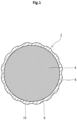
- a golf ball 2 shown in FIG. 1 includes a spherical core 4 and a cover 6 positioned outside the core 4.
- the golf ball 2 has a large number of dimples 8 on the surface thereof.
- a part other than the dimples 8 is a land 10.
- the golf ball 2 includes a paint layer and a mark layer on the external side of the cover 6, but these layers are not shown in the drawing.
- the golf ball 2 may have one or more mid layers between the core 4 and the cover 6.
- the golf ball 2 preferably has a diameter of not less than 40 mm and not greater than 45 mm. From the viewpoint of conformity to the rules established by the United States Golf Association (USGA), the diameter is particularly preferably not less than 42.67 mm. From the viewpoint of suppression of air resistance, the diameter is more preferably not greater than 44 mm and particularly preferably not greater than 42.80 mm.
- USGA United States Golf Association
- the golf ball 2 preferably has a mass of not less than 40 g and not greater than 50 g. From the viewpoint of attainment of great inertia, the mass is more preferably not less than 44 g and particularly preferably not less than 45.00 g. From the viewpoint of conformity to the rules established by the USGA, the mass is particularly preferably not greater than 45.93 g.
- the core 4 is formed by crosslinking a rubber composition.
- the base rubber of the rubber composition include polybutadienes, polyisoprenes, styrene-butadiene copolymers, ethylene-propylene-diene copolymers, and natural rubbers. Two or more rubbers may be used in combination. From the viewpoint of resilience performance, polybutadienes are preferable, and high-cis polybutadienes are particularly preferable.
- the rubber composition of the core 4 includes a co-crosslinking agent.
- co-crosslinking agents from the viewpoint of resilience performance are zinc acrylate, magnesium acrylate, zinc methacrylate, and magnesium methacrylate.
- the rubber composition preferably includes an organic peroxide together with a co-crosslinking agent. Examples of preferable organic peroxides include dicumyl peroxide, 1,1-bis(t-butylperoxy)-3,3,5-trimethylcyclohexane, 2,5-dimethyl-2,5-di(t-butylperoxy)hexane, and di-t-butyl peroxide.
- the rubber composition of the core 4 may include additives such as a filler, sulfur, a vulcanization accelerator, a sulfur compound, an anti-aging agent, a coloring agent, a plasticizer, and a dispersant.
- the rubber composition may include a carboxylic acid or a carboxylate.
- the rubber composition may include synthetic resin powder or crosslinked rubber powder.
- the core 4 has a diameter of preferably not less than 30.0 mm, more preferably not less than 37.0 mm, and particularly preferably not less than 38.0 mm.
- the diameter of the core 4 is preferably not greater than 42.0 mm, more preferably not greater than 41.5 mm, and particularly preferably not greater than 41.0 mm.
- the core 4 may have two or more layers.
- the core 4 may have a rib on the surface thereof.
- the core 4 may be hollow.
- the cover 6 is formed from a resin composition.
- a preferable base polymer for the resin composition is an ionomer resin.
- preferable ionomer resins include binary copolymers formed with an ⁇ -olefin and an ⁇ , ⁇ -unsaturated carboxylic acid having 3 to 8 carbon atoms.
- other preferable ionomer resins include ternary copolymers formed with: an ⁇ -olefin; an ⁇ , ⁇ -unsaturated carboxylic acid having 3 to 8 carbon atoms; and an ⁇ , ⁇ -unsaturated carboxylate ester having 2 to 22 carbon atoms.
- ⁇ -olefins are ethylene and propylene
- preferable ⁇ , ⁇ -unsaturated carboxylic acids are acrylic acid and methacrylic acid.
- some of the carboxyl groups are neutralized with metal ions.
- metal ions for neutralization include sodium ions, potassium ions, lithium ions, zinc ions, calcium ions, magnesium ions, aluminum ions, and neodymium ions.
- the resin composition of the cover 6 may include another polymer instead of or together with an ionomer resin.
- the other polymer include polyurethanes, polystyrenes, polyamides, polyesters, and polyolefins.
- the resin composition may include two or more polymers.
- the resin composition of the cover 6 may include a coloring agent such as titanium dioxide, a filler such as barium sulfate, a dispersant, and antioxidant, an ultraviolet absorber, a light stabilizer, a fluorescent material, a fluorescent brightener, etc.
- a coloring agent such as titanium dioxide
- a filler such as barium sulfate, a dispersant, and antioxidant
- an ultraviolet absorber such as a light stabilizer
- a fluorescent material such as tungsten and molybdenum
- the cover 6 has a thickness of preferably not less than 0.3 mm, more preferably not less than 1.0 mm, and particularly preferably not less than 1.5 mm.
- the thickness of the cover 6 is preferably not greater than 2.5 mm, more preferably not greater than 2.2 mm, and particularly preferably not greater than 2.0 mm.
- the cover 6 has a specific gravity of preferably not less than 0.90 and not greater than 1.10.
- the cover 6 may have two or more layers.
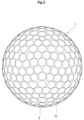
- each dimple 8 is circular.
- the golf ball 2 has dimples A each having a diameter of 4.40 mm; dimples B each having a diameter of 4.30 mm; dimples C each having a diameter of 4.15 mm; dimples D each having a diameter of 3.75 mm; and dimples E each having a diameter of 3.00 mm.
- the number of types of the dimples 8 is five.
- the number of the dimples A is 76; the number of the dimples B is 158; the number of the dimples C is 76; the number of the dimples D is 16; and the number of the dimples E is 8.
- the total number N of the dimples 8 is 334. A dimple pattern is formed by these dimples 8 and the land 10.
- FIG. 4 shows a cross section of the golf ball 2 along a plane passing through the central point of the dimple 8 and the central point of the golf ball 2.
- the up-down direction is the depth direction of the dimple 8.
- a chain double-dashed line 12 indicates a phantom sphere.
- the surface of the phantom sphere 12 is the surface of the golf ball 2 when it is postulated that no dimple 8 exists.
- the diameter of the phantom sphere 12 is equal to the diameter of the golf ball 2.
- the dimple 8 is recessed from the surface of the phantom sphere 12.
- the land 10 coincides with the surface of the phantom sphere 12.
- the cross-sectional shape of each dimple 8 is substantially a circular arc. The curvature radius of this circular arc is shown by reference character CR in FIG. 4 .
- an arrow Dm indicates the diameter of the dimple 8.
- the diameter Dm is the distance between two tangent points Ed appearing on a tangent line Tg that is drawn tangent to the opposite ends of the dimple 8.
- Each tangent point Ed is also the edge of the dimple 8.
- the edge Ed defines the contour of the dimple 8.
- the diameter Dm of each dimple 8 is preferably not less than 2.0 mm and not greater than 6.0 mm.
- the dimple 8 having a diameter Dm of not less than 2.0 mm contributes to turbulization. From this viewpoint, the diameter Dm is more preferably not less than 2.5 mm and particularly preferably not less than 2.8 mm.
- the dimple 8 having a diameter Dm of not greater than 6.0 mm does not impair a fundamental feature of the golf ball 2 being substantially a sphere. From this viewpoint, the diameter Dm is more preferably not greater than 5.5 mm and particularly preferably not greater than 5.0 mm.
- a double headed arrow Dp1 indicates a first depth of the dimple 8.
- the first depth Dp1 is the distance between the deepest part of the dimple 8 and the surface of the phantom sphere 12.
- a double headed arrow Dp2 indicates a second depth of the dimple 8.
- the second depth Dp2 is the distance between the deepest part of the dimple 8 and the tangent line Tg.
- the first depth Dp1 of each dimple 8 is preferably not less than 0.10 mm, more preferably not less than 0.13 mm, and particularly preferably not less than 0.15 mm. From the viewpoint of suppression of dropping of the golf ball 2 during flight, the first depth Dp1 is preferably not greater than 0.65 mm, more preferably not greater than 0.60 mm, and particularly preferably not greater than 0.55 mm.
- each dimple A is 15.21 mm 2 ; the area of each dimple B is 14.52 mm 2 ; the area of each dimple C is 13.53 mm 2 ; the area of each dimple D is 11.04 mm 2 ; and the area of each dimple E is 7.07 mm 2 .
- the ratio of the sum of the areas S of all the dimples 8 relative to the surface area of the phantom sphere 12 is referred to as an occupation ratio So.
- the occupation ratio So is preferably not less than 78%, more preferably not less than 80%, and particularly preferably not less than 82%.
- the occupation ratio So is preferably not greater than 95%.
- the total area of the dimples 8 is 4711.4 mm 2 .
- the surface area of the phantom sphere 12 of the golf ball 2 is 5728.0 mm 2 , so that the occupation ratio So is 82.3%.
- the total number N of the dimples 8 is preferably not less than 250 and not greater than 450.
- the total number N is more preferably not less than 270 and particularly preferably not less than 280.
- the total number N is more preferably not greater than 410 and particularly preferably not greater than 380.
- the "volume V of the dimple” means the volume of a portion surrounded by the surface of the phantom sphere 12 and the surface of the dimple 8.
- the total volume TV of the dimples 8 is preferably not less than 450 mm 3 and not greater than 750 mm 3 .
- the total volume TV is more preferably not less than 480 mm 3 and particularly preferably not less than 500 mm 3 .
- the total volume TV is more preferably not greater than 700 mm 3 and particularly preferably not greater than 670 mm 3 .
- the average volume Vave is preferably not less than 1.40 mm 3 and not greater than 2.10 mm 3 .
- the average volume Vave is more preferably not less than 1.50 mm 3 and particularly preferably not less than 1.55 mm 3 .
- the average volume Vave is more preferably not greater than 2.00 mm 3 and particularly preferably not greater than 1.95 mm 3 .
- the volume of each dimple A is 1.833 mm 3
- the volume of each dimple B is 1.713 mm 3
- the volume of each dimple C is 1.545 mm 3
- the volume of each dimple D is 1.159 mm 3
- the volume of each dimple E is 0.637 mm 3 . Therefore, the total volume TV of the dimples 8 is 551.1 mm 3 . Since the total number N of the dimples 8 of the golf ball 2 is 334, the average volume Vave is 1.650 mm 3 .
- a drag coefficient CD and a lift force coefficient CL of the golf ball 2 are measured under 15 conditions specified in an indoor test range (ITR) which is a rule set by the United States Golf Association (USGA).
- ITR indoor test range
- USGA United States Golf Association
- a trajectory of the golf ball 2 is calculated, using these drag coefficient CD and lift force coefficient CL, by a program created in accordance with a manual provided by the USGA. The following conditions are also inputted to the program.
- a horizontal component Vx of the speed of the golf ball 2 and a vertical component Vy of the speed of the golf ball 2 can be calculated per 0.1 seconds from a launch point to a landing point.
- a vector angle A is calculated from the horizontal component Vx and the vertical component Vy by the following mathematical formula.
- A ATAN Vy / Vx
- the vector angle A is calculated by an inverse tangent function of a ratio (Vy / Vx).
- the vector angle A (degree) is obtained per 0.1 seconds from the launch point to the landing point by this calculation. For example, for a trajectory having a flight duration of 5.5 seconds, 55 vector angles A are obtained.
- the maximum value among a plurality of vector angles A from a launch point to a landing point is referred to as maximum vector angle Amax (degree).
- the maximum vector angle Amax influences a trajectory upon a shot with a utility club. From the viewpoint that an appropriate trajectory can be achieved upon a shot with a utility club, the maximum vector angle Amax is preferably not less than 18.50 degrees and not greater than 22.50 degrees.
- the maximum vector angle Amax is more preferably not less than 19.50 degrees and particularly preferably not less than 20.00 degrees.
- the maximum vector angle Amax is more preferably not greater than 21.50 degrees and particularly preferably not greater than 21.00 degrees.
- FIG. 5 is a graph showing a relationship between the average volume Vave of the dimples 8 and the maximum vector angle Amax.
- a point indicated by reference character P1 is a plot of the golf ball 2 shown in FIGS. 1 to 4 .
- a straight line indicated by reference character L1 is represented by the following mathematical formula.
- Amax 4.0 * Vave + 13.10
- the point P1 is located above the straight line L1.
- the golf ball 2 satisfies the following mathematical formula (1).
- the volume V of each dimple 8 is small, and the maximum vector angle Amax is large. According to the finding by the present inventors, a trajectory obtained when the golf ball 2 that satisfies the mathematical formula (1) is hit with a utility club is appropriate. The golf ball 2 has excellent flight performance upon a shot with a utility club.
- a straight line indicated by reference character L2 is represented by the following mathematical formula.
- Amax 4.0 * Vave + 13.24
- the point P1 is located above the straight line L2.
- the golf ball 2 satisfies the following mathematical formula (2).
- Amax ⁇ 4.0 * Vave + 13.24 In the golf ball 2, the volume V of each dimple 8 is small, and the maximum vector angle Amax is large. According to the finding by the present inventors, a trajectory obtained when the golf ball 2 that satisfies the mathematical formula (2) is hit with a utility club is appropriate. The golf ball 2 has excellent flight performance upon a shot with a utility club.
- a straight line indicated by reference character L3 is represented by the following mathematical formula.
- Amax 4.0 * Vave + 13.73
- the point P1 is located on the straight line L3.
- the golf ball 2 satisfies the following mathematical formula (3).
- the volume V of each dimple 8 is small, and the maximum vector angle Amax is large. According to the finding by the present inventors, a trajectory obtained when the golf ball 2 that satisfies the mathematical formula (3) is hit with a utility club is appropriate.
- the golf ball 2 has excellent flight performance upon a shot with a utility club.
- a value (Amax - 4.0 ⁇ Vave) is 13.10.
- the value (Amax - 4.0 ⁇ Vave) is 13.24.
- the value (Amax - 4.0 ⁇ Vave) is 13.73.
- the value (Amax - 4.0 ⁇ Vave) is preferably not less than 13.10, more preferably not less than 13.24, and particularly preferably not less than 13.73.
- a rubber composition was obtained by kneading 100 parts by mass of a polybutadiene (trade name "BR-730", manufactured by JSR Corporation), 30 parts by mass of zinc acrylate, 6 parts by mass of zinc oxide, 10 parts by mass of barium sulfate, 0.5 parts by mass of diphenyl disulfide, and 0.5 parts by mass of dicumyl peroxide.
- This rubber composition was placed into a mold including upper and lower mold halves each having a hemispherical cavity, and heated at 170°C for 18 minutes to obtain a core having a diameter of 39.7 mm.
- a resin composition was obtained by kneading 50 parts by mass of an ionomer resin (trade name "Himilan 1605", manufactured by DOW-MITSUI POLYCHEMICALS COMPANY, LTD.), 50 parts by mass of another ionomer resin (trade name "Himilan 1706", manufactured by DOW-MITSUI POLYCHEMICALS COMPANY, LTD.), and 3 parts by mass of titanium dioxide.
- the above core was placed into a final mold having a large number of pimples on the inside face thereof, and the above resin composition was injected around the core by injection molding to form a cover having a thickness of 1.5 mm. A large number of dimples having a shape that is the inverted shape of the pimples were formed on the cover.
- a clear paint including a two-component curing type polyurethane as a base material was applied to this cover to obtain a golf ball of Example 1 having a diameter of about 42.7 mm and a mass of about 45.4 g.
- the golf ball has a PGA compression of about 85.
- the golf ball has the dimple pattern shown in FIGS. 2 and 3 . The specifications of the dimples are shown in detail in Table 1 below.
- Example 2 Golf balls of Example 2 and Comparative Examples 1 and 2 were obtained in the same manner as Example 1, except that the final mold was changed. Each of these golf balls has the dimple pattern shown in FIGS. 2 and 3 . The specifications of the dimples of these golf balls are shown in Tables 2 to 4 below.
- Example 3 A golf ball of Example 3 was obtained in the same manner as Example 1, except that the final mold was changed.
- the dimple pattern of this golf ball is shown in FIGS. 6 and 7 .
- the specifications of the dimples of this golf ball are shown in Table 5 below.
- a utility club (trade name "XXIO-12 Hybrid H#3", manufactured by Sumitomo Rubber Industries, Ltd., shaft hardness: S, loft angle: 18°) was attached to a swing machine manufactured by Golf Laboratories, Inc.
- a golf ball was hit under a condition of a head speed of 41.5 m/sec, and the flight distance was measured.
- the flight distance is the distance from the hitting spot to the spot at which the golf ball stopped.
- the measurement was conducted 12 times, and the average value of the obtained data was calculated. The results are shown in Tables 6 to 9 below.
- the golf ball of each Example has excellent flight performance upon a shot with a utility club. From the evaluation results, advantages of this golf ball are clear.
- a golf ball having a plurality of dimples on a surface thereof, wherein a trajectory calculated using a drag coefficient CD and a lift force coefficient CL obtained in an indoor test range which is a rule set by the United States Golf Association, on the basis of a model proposed by S. J.
- a golf ball having a plurality of dimples on a surface thereof, wherein
- the above-described golf ball is suitable for, for example, playing golf on golf courses and practicing at driving ranges.
Landscapes
- Health & Medical Sciences (AREA)
- General Health & Medical Sciences (AREA)
- Physical Education & Sports Medicine (AREA)
- Golf Clubs (AREA)
- Compositions Of Macromolecular Compounds (AREA)
Abstract
Description
- The present specification discloses a golf ball having a large number of dimples on the surface thereof.
- Golf balls have a large number of dimples on the surfaces thereof. The dimples disturb the air flow around the golf ball during flight to cause turbulent flow separation. This phenomenon is referred to as "turbulization". Due to turbulization, separation points of the air from the golf ball shift backwards leading to a reduction of drag. The turbulization promotes the displacement between the separation point on the upper side and the separation point on the lower side of the golf ball, which results from the backspin, thereby enhancing the lift force that acts upon the golf ball. The reduction of drag and the enhancement of lift force are referred to as a "dimple effect". Excellent dimples efficiently disturb the air flow. Excellent dimples produce a large flight distance.
- An interest to golf players concerning golf balls is flight performance. Golf players prefer a golf ball with which a flight distance is large when the golf ball is hit with a driver (W#1).
Japanese Laid-Open Patent Publication No. 2014-140638 - Golf players frequently use utility clubs for tee shots on par-three holes. Golf players also frequently use utility clubs for second shots on long-distance holes. Golf players are also interested in a flight distance upon hitting with a utility club.
- It is an intention of the applicant to provide a golf ball having excellent flight performance when being hit with a utility club.
- A golf ball according to an embodiment has a plurality of dimples on a surface thereof. A trajectory calculated using a drag coefficient CD and a lift force coefficient CL obtained in an indoor test range which is a rule set by the United States Golf Association, on the basis of a model proposed by S. J. Quintavalla of the United States Golf Association and disclosed in "Science and Golf IV, Chapter 30, A Generally Applicable Model for the Aerodynamic Behavior of Golf Balls" published in 2002, by a program created in accordance with a manual provided by the United States Golf Association, under conditions of an initial speed of 260 ft/s, a launch angle of 15.0 degrees, and an initial backspin rate of 3000 rpm, satisfies the following mathematical formula,


- This golf ball has excellent flight performance upon a shot with a utility club.
-
-
FIG. 1 is a cross-sectional view schematically showing a golf ball according to an embodiment; -
FIG. 2 is an enlarged plan view showing the golf ball inFIG. 1 ; -
FIG. 3 is a front view showing the golf ball inFIG. 2 ; -
FIG. 4 is an enlarged cross-sectional view showing a part of the golf ball inFIG. 1 ; -
FIG. 5 is a graph showing a relationship between an average volume of dimples and a maximum vector angle of the golf ball inFIG. 1 ; -
FIG. 6 is a plan view showing a golf ball of Example 3; and -
FIG. 7 is a front view showing the golf ball inFIG. 6 . - Hereinafter, preferred embodiments will be described in detail with appropriate reference to the drawings.
- A
golf ball 2 shown inFIG. 1 includes aspherical core 4 and acover 6 positioned outside thecore 4. Thegolf ball 2 has a large number ofdimples 8 on the surface thereof. Of the surface of thegolf ball 2, a part other than thedimples 8 is aland 10. Thegolf ball 2 includes a paint layer and a mark layer on the external side of thecover 6, but these layers are not shown in the drawing. Thegolf ball 2 may have one or more mid layers between thecore 4 and thecover 6. - The
golf ball 2 preferably has a diameter of not less than 40 mm and not greater than 45 mm. From the viewpoint of conformity to the rules established by the United States Golf Association (USGA), the diameter is particularly preferably not less than 42.67 mm. From the viewpoint of suppression of air resistance, the diameter is more preferably not greater than 44 mm and particularly preferably not greater than 42.80 mm. - The
golf ball 2 preferably has a mass of not less than 40 g and not greater than 50 g. From the viewpoint of attainment of great inertia, the mass is more preferably not less than 44 g and particularly preferably not less than 45.00 g. From the viewpoint of conformity to the rules established by the USGA, the mass is particularly preferably not greater than 45.93 g. - The
core 4 is formed by crosslinking a rubber composition. Examples of the base rubber of the rubber composition include polybutadienes, polyisoprenes, styrene-butadiene copolymers, ethylene-propylene-diene copolymers, and natural rubbers. Two or more rubbers may be used in combination. From the viewpoint of resilience performance, polybutadienes are preferable, and high-cis polybutadienes are particularly preferable. - The rubber composition of the
core 4 includes a co-crosslinking agent. Preferable co-crosslinking agents from the viewpoint of resilience performance are zinc acrylate, magnesium acrylate, zinc methacrylate, and magnesium methacrylate. The rubber composition preferably includes an organic peroxide together with a co-crosslinking agent. Examples of preferable organic peroxides include dicumyl peroxide, 1,1-bis(t-butylperoxy)-3,3,5-trimethylcyclohexane, 2,5-dimethyl-2,5-di(t-butylperoxy)hexane, and di-t-butyl peroxide. - The rubber composition of the
core 4 may include additives such as a filler, sulfur, a vulcanization accelerator, a sulfur compound, an anti-aging agent, a coloring agent, a plasticizer, and a dispersant. The rubber composition may include a carboxylic acid or a carboxylate. The rubber composition may include synthetic resin powder or crosslinked rubber powder. - The
core 4 has a diameter of preferably not less than 30.0 mm, more preferably not less than 37.0 mm, and particularly preferably not less than 38.0 mm. The diameter of thecore 4 is preferably not greater than 42.0 mm, more preferably not greater than 41.5 mm, and particularly preferably not greater than 41.0 mm. Thecore 4 may have two or more layers. Thecore 4 may have a rib on the surface thereof. Thecore 4 may be hollow. - The
cover 6 is formed from a resin composition. A preferable base polymer for the resin composition is an ionomer resin. Examples of preferable ionomer resins include binary copolymers formed with an α-olefin and an α,β-unsaturated carboxylic acid having 3 to 8 carbon atoms. Examples of other preferable ionomer resins include ternary copolymers formed with: an α-olefin; an α,β-unsaturated carboxylic acid having 3 to 8 carbon atoms; and an α,β-unsaturated carboxylate ester having 2 to 22 carbon atoms. For the binary copolymers and the ternary copolymers, preferable α-olefins are ethylene and propylene, and preferable α,β-unsaturated carboxylic acids are acrylic acid and methacrylic acid. In the binary copolymers and the ternary copolymers, some of the carboxyl groups are neutralized with metal ions. Examples of metal ions for neutralization include sodium ions, potassium ions, lithium ions, zinc ions, calcium ions, magnesium ions, aluminum ions, and neodymium ions. - The resin composition of the
cover 6 may include another polymer instead of or together with an ionomer resin. Examples of the other polymer include polyurethanes, polystyrenes, polyamides, polyesters, and polyolefins. The resin composition may include two or more polymers. - The resin composition of the
cover 6 may include a coloring agent such as titanium dioxide, a filler such as barium sulfate, a dispersant, and antioxidant, an ultraviolet absorber, a light stabilizer, a fluorescent material, a fluorescent brightener, etc. For the purpose of specific gravity adjustment, the resin composition may include powder of a metal with a high specific gravity such as tungsten and molybdenum. - The
cover 6 has a thickness of preferably not less than 0.3 mm, more preferably not less than 1.0 mm, and particularly preferably not less than 1.5 mm. The thickness of thecover 6 is preferably not greater than 2.5 mm, more preferably not greater than 2.2 mm, and particularly preferably not greater than 2.0 mm. Thecover 6 has a specific gravity of preferably not less than 0.90 and not greater than 1.10. Thecover 6 may have two or more layers. - As shown in
FIGS. 2 and3 , the contour of eachdimple 8 is circular. Thegolf ball 2 has dimples A each having a diameter of 4.40 mm; dimples B each having a diameter of 4.30 mm; dimples C each having a diameter of 4.15 mm; dimples D each having a diameter of 3.75 mm; and dimples E each having a diameter of 3.00 mm. The number of types of thedimples 8 is five. - The number of the dimples A is 76; the number of the dimples B is 158; the number of the dimples C is 76; the number of the dimples D is 16; and the number of the dimples E is 8. The total number N of the
dimples 8 is 334. A dimple pattern is formed by thesedimples 8 and theland 10. -
FIG. 4 shows a cross section of thegolf ball 2 along a plane passing through the central point of thedimple 8 and the central point of thegolf ball 2. InFIG. 4 , the up-down direction is the depth direction of thedimple 8. InFIG. 4 , a chain double-dashedline 12 indicates a phantom sphere. The surface of thephantom sphere 12 is the surface of thegolf ball 2 when it is postulated that nodimple 8 exists. The diameter of thephantom sphere 12 is equal to the diameter of thegolf ball 2. Thedimple 8 is recessed from the surface of thephantom sphere 12. Theland 10 coincides with the surface of thephantom sphere 12. In the present embodiment, the cross-sectional shape of eachdimple 8 is substantially a circular arc. The curvature radius of this circular arc is shown by reference character CR inFIG. 4 . - In
FIG. 4 , an arrow Dm indicates the diameter of thedimple 8. The diameter Dm is the distance between two tangent points Ed appearing on a tangent line Tg that is drawn tangent to the opposite ends of thedimple 8. Each tangent point Ed is also the edge of thedimple 8. The edge Ed defines the contour of thedimple 8. - The diameter Dm of each
dimple 8 is preferably not less than 2.0 mm and not greater than 6.0 mm. Thedimple 8 having a diameter Dm of not less than 2.0 mm contributes to turbulization. From this viewpoint, the diameter Dm is more preferably not less than 2.5 mm and particularly preferably not less than 2.8 mm. Thedimple 8 having a diameter Dm of not greater than 6.0 mm does not impair a fundamental feature of thegolf ball 2 being substantially a sphere. From this viewpoint, the diameter Dm is more preferably not greater than 5.5 mm and particularly preferably not greater than 5.0 mm. - In
FIG. 4 , a double headed arrow Dp1 indicates a first depth of thedimple 8. The first depth Dp1 is the distance between the deepest part of thedimple 8 and the surface of thephantom sphere 12. InFIG. 4 , a double headed arrow Dp2 indicates a second depth of thedimple 8. The second depth Dp2 is the distance between the deepest part of thedimple 8 and the tangent line Tg. - From the viewpoint of suppression of rising of the
golf ball 2 during flight, the first depth Dp1 of eachdimple 8 is preferably not less than 0.10 mm, more preferably not less than 0.13 mm, and particularly preferably not less than 0.15 mm. From the viewpoint of suppression of dropping of thegolf ball 2 during flight, the first depth Dp1 is preferably not greater than 0.65 mm, more preferably not greater than 0.60 mm, and particularly preferably not greater than 0.55 mm. - The area S of the
dimple 8 is the area of a region surrounded by the contour line of thedimple 8 when the central point of thegolf ball 2 is viewed at infinity. In the case of acircular dimple 8, the area S is calculated by the following mathematical formula.
- In the
golf ball 2 shown inFIGS. 2 and3 , the area of each dimple A is 15.21 mm2; the area of each dimple B is 14.52 mm2; the area of each dimple C is 13.53 mm2; the area of each dimple D is 11.04 mm2; and the area of each dimple E is 7.07 mm2. - In the present specification, the ratio of the sum of the areas S of all the
dimples 8 relative to the surface area of thephantom sphere 12 is referred to as an occupation ratio So. From the viewpoint of achieving sufficient turbulization, the occupation ratio So is preferably not less than 78%, more preferably not less than 80%, and particularly preferably not less than 82%. The occupation ratio So is preferably not greater than 95%. In thegolf ball 2 shown inFIGS. 2 and3 , the total area of thedimples 8 is 4711.4 mm2. The surface area of thephantom sphere 12 of thegolf ball 2 is 5728.0 mm2, so that the occupation ratio So is 82.3%. - From the viewpoint that an appropriate trajectory can be achieved upon a shot with a utility club, the total number N of the
dimples 8 is preferably not less than 250 and not greater than 450. The total number N is more preferably not less than 270 and particularly preferably not less than 280. The total number N is more preferably not greater than 410 and particularly preferably not greater than 380. - In the present specification, the "volume V of the dimple" means the volume of a portion surrounded by the surface of the
phantom sphere 12 and the surface of thedimple 8. The total volume TV of thedimples 8 is preferably not less than 450 mm3 and not greater than 750 mm3. With thegolf ball 2 in which the total volume TV is not less than 450 mm3, rising of thegolf ball 2 during flight is suppressed. From this viewpoint, the total volume TV is more preferably not less than 480 mm3 and particularly preferably not less than 500 mm3. With thegolf ball 2 in which the total volume TV is not greater than 750 mm3, dropping of thegolf ball 2 during flight is suppressed. From this viewpoint, the total volume TV is more preferably not greater than 700 mm3 and particularly preferably not greater than 670 mm3. - In the present specification, an average volume Vave (mm3) of the
dimples 8 is calculated by the following mathematical formula.
- From the viewpoint that an appropriate trajectory can be achieved upon a shot with a utility club, the average volume Vave is preferably not less than 1.40 mm3 and not greater than 2.10 mm3. The average volume Vave is more preferably not less than 1.50 mm3 and particularly preferably not less than 1.55 mm3. The average volume Vave is more preferably not greater than 2.00 mm3 and particularly preferably not greater than 1.95 mm3.
- In the
golf ball 2 shown inFIGS. 2 and3 , the volume of each dimple A is 1.833 mm3, the volume of each dimple B is 1.713 mm3, the volume of each dimple C is 1.545 mm3, the volume of each dimple D is 1.159 mm3, and the volume of each dimple E is 0.637 mm3. Therefore, the total volume TV of thedimples 8 is 551.1 mm3. Since the total number N of thedimples 8 of thegolf ball 2 is 334, the average volume Vave is 1.650 mm3. - In the present specification, a drag coefficient CD and a lift force coefficient CL of the
golf ball 2 are measured under 15 conditions specified in an indoor test range (ITR) which is a rule set by the United States Golf Association (USGA). A trajectory of thegolf ball 2 is calculated, using these drag coefficient CD and lift force coefficient CL, by a program created in accordance with a manual provided by the USGA. The following conditions are also inputted to the program. - Initial ball speed: 260 ft/s (260 feet per second)
- Launch angle: 15.0 degrees
- Initial backspin rate: 3000 rpm
- By calculating the trajectory, a horizontal component Vx of the speed of the
golf ball 2 and a vertical component Vy of the speed of thegolf ball 2 can be calculated per 0.1 seconds from a launch point to a landing point. A vector angle A is calculated from the horizontal component Vx and the vertical component Vy by the following mathematical formula.
- In the present specification, the maximum value among a plurality of vector angles A from a launch point to a landing point is referred to as maximum vector angle Amax (degree). According to the finding by the present inventors, the maximum vector angle Amax influences a trajectory upon a shot with a utility club. From the viewpoint that an appropriate trajectory can be achieved upon a shot with a utility club, the maximum vector angle Amax is preferably not less than 18.50 degrees and not greater than 22.50 degrees. The maximum vector angle Amax is more preferably not less than 19.50 degrees and particularly preferably not less than 20.00 degrees. The maximum vector angle Amax is more preferably not greater than 21.50 degrees and particularly preferably not greater than 21.00 degrees.
-
FIG. 5 is a graph showing a relationship between the average volume Vave of thedimples 8 and the maximum vector angle Amax. InFIG. 5 , a point indicated by reference character P1 is a plot of thegolf ball 2 shown inFIGS. 1 to 4 . - In
FIG. 5 , a straight line indicated by reference character L1 is represented by the following mathematical formula.
FIG. 5 , the point P1 is located above the straight line L1. In other words, thegolf ball 2 satisfies the following mathematical formula (1).
golf ball 2, the volume V of eachdimple 8 is small, and the maximum vector angle Amax is large. According to the finding by the present inventors, a trajectory obtained when thegolf ball 2 that satisfies the mathematical formula (1) is hit with a utility club is appropriate. Thegolf ball 2 has excellent flight performance upon a shot with a utility club. - In
FIG. 5 , a straight line indicated by reference character L2 is represented by the following mathematical formula.
FIG. 5 , the point P1 is located above the straight line L2. In other words, thegolf ball 2 satisfies the following mathematical formula (2).
golf ball 2, the volume V of eachdimple 8 is small, and the maximum vector angle Amax is large. According to the finding by the present inventors, a trajectory obtained when thegolf ball 2 that satisfies the mathematical formula (2) is hit with a utility club is appropriate. Thegolf ball 2 has excellent flight performance upon a shot with a utility club. - In
FIG. 5 , a straight line indicated by reference character L3 is represented by the following mathematical formula.
FIG. 5 , the point P1 is located on the straight line L3. In other words, thegolf ball 2 satisfies the following mathematical formula (3).
golf ball 2, the volume V of eachdimple 8 is small, and the maximum vector angle Amax is large. According to the finding by the present inventors, a trajectory obtained when thegolf ball 2 that satisfies the mathematical formula (3) is hit with a utility club is appropriate. Thegolf ball 2 has excellent flight performance upon a shot with a utility club. - For the
golf ball 2 on the straight line L1, a value (Amax - 4.0 ∗ Vave) is 13.10. For thegolf ball 2 on the straight line L2, the value (Amax - 4.0 ∗ Vave) is 13.24. For thegolf ball 2 on the straight line L3, the value (Amax - 4.0 ∗ Vave) is 13.73. From the viewpoint of flight performance upon a shot with a utility club, the value (Amax - 4.0 ∗ Vave) is preferably not less than 13.10, more preferably not less than 13.24, and particularly preferably not less than 13.73. - Hereinafter, the advantageous effects of golf balls according to Examples will be shown, but the scope disclosed in the present specification should not be construed in a limited manner on the basis of the description of these Examples.
- A rubber composition was obtained by kneading 100 parts by mass of a polybutadiene (trade name "BR-730", manufactured by JSR Corporation), 30 parts by mass of zinc acrylate, 6 parts by mass of zinc oxide, 10 parts by mass of barium sulfate, 0.5 parts by mass of diphenyl disulfide, and 0.5 parts by mass of dicumyl peroxide. This rubber composition was placed into a mold including upper and lower mold halves each having a hemispherical cavity, and heated at 170°C for 18 minutes to obtain a core having a diameter of 39.7 mm. Meanwhile, a resin composition was obtained by kneading 50 parts by mass of an ionomer resin (trade name "Himilan 1605", manufactured by DOW-MITSUI POLYCHEMICALS COMPANY, LTD.), 50 parts by mass of another ionomer resin (trade name "Himilan 1706", manufactured by DOW-MITSUI POLYCHEMICALS COMPANY, LTD.), and 3 parts by mass of titanium dioxide. The above core was placed into a final mold having a large number of pimples on the inside face thereof, and the above resin composition was injected around the core by injection molding to form a cover having a thickness of 1.5 mm. A large number of dimples having a shape that is the inverted shape of the pimples were formed on the cover. A clear paint including a two-component curing type polyurethane as a base material was applied to this cover to obtain a golf ball of Example 1 having a diameter of about 42.7 mm and a mass of about 45.4 g. The golf ball has a PGA compression of about 85. The golf ball has the dimple pattern shown in
FIGS. 2 and3 . The specifications of the dimples are shown in detail in Table 1 below. - Golf balls of Example 2 and Comparative Examples 1 and 2 were obtained in the same manner as Example 1, except that the final mold was changed. Each of these golf balls has the dimple pattern shown in
FIGS. 2 and3 . The specifications of the dimples of these golf balls are shown in Tables 2 to 4 below. - A golf ball of Example 3 was obtained in the same manner as Example 1, except that the final mold was changed. The dimple pattern of this golf ball is shown in
FIGS. 6 and7 . The specifications of the dimples of this golf ball are shown in Table 5 below. - Commercially available golf balls were prepared as Comparative Examples 3 to 16.
- A utility club (trade name "XXIO-12 Hybrid H#3", manufactured by Sumitomo Rubber Industries, Ltd., shaft hardness: S, loft angle: 18°) was attached to a swing machine manufactured by Golf Laboratories, Inc. A golf ball was hit under a condition of a head speed of 41.5 m/sec, and the flight distance was measured. The flight distance is the distance from the hitting spot to the spot at which the golf ball stopped. The measurement was conducted 12 times, and the average value of the obtained data was calculated. The results are shown in Tables 6 to 9 below.
-
Table 1 Specifications of Dimples Example 1 Number Dm (mm) Dp2 (mm) Dp1 (mm) CR (mm) V (mm3) Total (mm3) A 76 4.40 0.1272 0.2409 19.09 1.833 139.3 B 158 4.30 0.1272 0.2357 18.23 1.713 270.7 C 76 4.15 0.1272 0.2283 16.99 1.545 117.5 D 16 3.75 0.1272 0.2097 13.88 1.159 18.5 E 8 3.00 0.1272 0.1800 8.91 0.637 5.1 334 551.1 -
Table 2 Specifications of Dimples Example 2 Number Dm (mm) Dp2 (mm) Dp1 (mm) CR (mm) V (mm3) Total (mm3) A 76 4.40 0.1336 0.2473 18.18 1.882 143.0 B 158 4.30 0.1336 0.2421 17.37 1.760 278.1 C 76 4.15 0.1336 0.2347 16.18 1.589 120.8 D 16 3.75 0.1336 0.2161 13.22 1.195 19.1 E 8 3.00 0.1336 0.1864 8.49 0.660 5.3 334 566.3 -
Table 3 Specifications of Dimples Comparative Example 1 Number Dm (mm) Dp2 (mm) Dp1 (mm) CR (mm) V (mm3) Total (mm3) A 76 4.40 0.1399 0.2536 17.37 1.930 146.7 B 158 4.30 0.1399 0.2484 16.59 1.806 285.3 C 76 4.15 0.1399 0.2410 15.46 1.632 124.0 D 16 3.75 0.1399 0.2224 12.63 1.230 19.7 E 8 3.00 0.1399 0.1927 8.11 0.682 5.5 334 581.2 -
Table 4 Specifications of Dimples Comparative Example 2 Number Dm (mm) Dp2 (mm) Dp1 (mm) CR (mm) V (mm3) Total (mm3) A 76 4.40 0.1462 0.2599 16.63 1.978 150.3 B 158 4.30 0.1462 0.2547 15.88 1.852 292.6 C 76 4.15 0.1462 0.2473 14.80 1.675 127.3 D 16 3.75 0.1462 0.2287 12.10 1.265 20.2 E 8 3.00 0.1462 0.1990 7.77 0.705 5.6 334 596.1 -
Table 5 Specifications of Dimples Example 3 Number Dm (mm) Dp2 (mm) Dp1 (mm) CR (mm) V (mm3) Total (mm3) A 30 4.70 0.1170 0.2467 23.66 2.142 64.3 B 132 4.60 0.1170 0.2412 22.67 2.007 264.9 C 48 4.50 0.1170 0.2359 21.69 1.878 90.1 D 90 4.30 0.1170 0.2255 19.81 1.639 147.5 E 12 3.00 0.1170 0.1698 9.67 0.601 7.2 312 574.0 -
Table 6 Evaluation Results Example 1 Example 2 Comparative Example 1 Comparative Example 2 Example 3 Front view FIG. 2 FIG. 2 FIG. 2 FIG. 2 FIG. 6 Plan view FIG. 3 FIG. 3 FIG. 3 FIG. 3 FIG. 7 N 334 334 334 334 312 TV (mm3) 551.1 566.3 581.2 596.1 574.0 Vave (mm3) 1.650 1.695 1.740 1.785 1.840 Amax (deg.) 20.33 20.07 19.78 19.43 20.60 Amax - 4.0 * Vave 13.73 13.29 12.82 12.29 13.24 Flight distance (m) 196.0 195.0 193.5 191.5 194.7 -
Table 7 Evaluation Results Comparative Example 3 Comparative Example 4 Comparative Example 5 Comparative Example 6 Comparative Example 7 Front view - - - - - Plan view - - - - - N 348 352 328 352 346 TV (mm3) 570.1 591.7 583.2 567.2 564.4 Vave (mm3) 1.638 1.681 1.778 1.611 1.631 Amax (deg.) 19.07 19.32 19.58 18.93 19.26 Amax - 4.0 * Vave 12.52 12.60 12.47 12.48 12.73 Flight distance (m) 193.1 193.0 192.1 193.2 193.3 -
Table 8 Evaluation Results Comparative Example 8 Comparative Example 9 Comparative Example 10 Comparative Example 11 Comparative Example 12 Front view - - - - - Plan view - - - - - N 330 330 338 338 338 TV (mm3) 586.5 572.4 567.2 574.6 593.6 Vave (mm3) 1.777 1.735 1.678 1.700 1.756 Amax (deg.) 19.57 19.52 19.65 19.66 19.14 Amax - 4.0 * Vave 12.46 12.58 12.94 12.86 12.11 Flight distance (m) 192.2 192.9 194.1 193.8 191.3 -
Table 9 Evaluation Results Comparative Example 13 Comparative Example 14 Comparative Example 15 Comparative Example 16 Front view - - - - Plan view - - - - N 326 332 332 332 TV (mm3) 605.7 610.1 554.7 588.0 Vave (mm3) 1.858 1.838 1.671 1.771 Amax (deg.) 20.20 19.60 19.66 20.09 Amax - 4.0 * Vave 12.77 12.25 12.98 13.01 Flight distance (m) 192.8 191.1 194.2 194.0 - As shown in Tables 6 to 9, the golf ball of each Example has excellent flight performance upon a shot with a utility club. From the evaluation results, advantages of this golf ball are clear.
- Each of the following items is the disclosure of a preferred embodiment.
- A golf ball having a plurality of dimples on a surface thereof, wherein
a trajectory calculated using a drag coefficient CD and a lift force coefficient CL obtained in an indoor test range which is a rule set by the United States Golf Association, on the basis of a model proposed by S. J. Quintavalla of the United States Golf Association and disclosed in "Science and Golf IV, Chapter 30, A Generally Applicable Model for the Aerodynamic Behavior of Golf Balls" published in 2002, by a program created in accordance with a manual provided by the United States Golf Association, under conditions of an initial speed of 260 ft/s, a launch angle of 15.0 degrees, and an initial backspin rate of 3000 rpm, satisfies the following mathematical formula,
the vector angle A is calculated by the following mathematical formula,
- The golf ball according to Item 1, wherein a total number of the dimples is not less than 280 and not greater than 380.
- The golf ball according to
Item 1 or 2, wherein the average volume Vave is not less than 1.40 mm3 and not greater than 2.10 mm3. - A golf ball having a plurality of dimples on a surface thereof, wherein
- a value (Amax - 4.0 ∗ Vave) in a trajectory calculated using a drag coefficient CD and a lift force coefficient CL obtained in an indoor test range which is a rule set by the United States Golf Association, on the basis of a model proposed by S. J. Quintavalla of the United States Golf Association and disclosed in "Science and Golf IV, Chapter 30, A Generally Applicable Model for the Aerodynamic Behavior of Golf Balls" published in 2002, by a program created in accordance with a manual provided by the United States Golf Association, under conditions of an initial speed of 260 ft/s, a launch angle of 15.0 degrees, and an initial backspin rate of 3000 rpm, is not less than 13.10,
- Vave being an average volume (mm3) of the dimples,
- Amax being a maximum value (degree) of a vector angle A calculated by the following mathematical formula, in the trajectory,

- The above-described golf ball is suitable for, for example, playing golf on golf courses and practicing at driving ranges.
Claims (3)
- A golf ball (2) having a plurality of dimples (8) on a surface thereof, wherein a trajectory calculated using a drag coefficient CD and a lift force coefficient CL obtained in an indoor test range which is a rule set by the United States Golf Association, on the basis of a model proposed by S. J. Quintavalla of the United States Golf Association and disclosed in "Science and Golf IV, Chapter 30, A Generally Applicable Model for the Aerodynamic Behavior of Golf Balls" published in 2002, by a program created in accordance with a manual provided by the United States Golf Association, under conditions of an initial speed of 260 ft/s, a launch angle of 15.0 degrees, and an initial backspin rate of 3000 rpm, satisfies the following mathematical formula,
 wherein Amax represents a maximum value (degree) of a vector angle A in the trajectory, andVave represents an average volume (mm3) of the dimples (8), andthe vector angle A is calculated by the following mathematical formula,
- The golf ball (2) according to claim 1, wherein a total number (N) of the dimples (8) is not less than 280 and not greater than 380.
- The golf ball (2) according to claim 1 or 2, wherein the average volume Vave is not less than 1.40 mm3 and not greater than 2.10 mm3.
Applications Claiming Priority (1)
| Application Number | Priority Date | Filing Date | Title |
|---|---|---|---|
| JP2022013357A JP7859071B2 (en) | 2022-01-31 | golf ball |
Publications (1)
| Publication Number | Publication Date |
|---|---|
| EP4218964A1 true EP4218964A1 (en) | 2023-08-02 |
Family
ID=84943220
Family Applications (1)
| Application Number | Title | Priority Date | Filing Date |
|---|---|---|---|
| EP23151354.0A Pending EP4218964A1 (en) | 2022-01-31 | 2023-01-12 | Golf ball |
Country Status (3)
| Country | Link |
|---|---|
| US (1) | US20230241459A1 (en) |
| EP (1) | EP4218964A1 (en) |
| KR (1) | KR20230117512A (en) |
Citations (2)
| Publication number | Priority date | Publication date | Assignee | Title |
|---|---|---|---|---|
| JP2003210613A (en) * | 2002-01-17 | 2003-07-29 | Sumitomo Rubber Ind Ltd | Golf ball |
| JP2014140638A (en) | 2012-12-28 | 2014-08-07 | Dunlop Sports Co Ltd | Golf ball |
-
2023
- 2023-01-09 KR KR1020230002780A patent/KR20230117512A/en active Pending
- 2023-01-12 EP EP23151354.0A patent/EP4218964A1/en active Pending
- 2023-01-31 US US18/103,518 patent/US20230241459A1/en not_active Abandoned
Patent Citations (2)
| Publication number | Priority date | Publication date | Assignee | Title |
|---|---|---|---|---|
| JP2003210613A (en) * | 2002-01-17 | 2003-07-29 | Sumitomo Rubber Ind Ltd | Golf ball |
| JP2014140638A (en) | 2012-12-28 | 2014-08-07 | Dunlop Sports Co Ltd | Golf ball |
Non-Patent Citations (2)
| Title |
|---|
| S. J. QUINTAVALLA, SCIENCE AND GOLF IV, CHAPTER 30, A GENERALLY APPLICABLE MODEL FOR THE AERODYNAMIC BEHAVIOR OF GOLF BALLS, 2002 |
| S. J. QUINTAVALLA: "Science and Golf IV", 2002, UNITED STATES GOLF ASSOCIATION, article "A Generally Applicable Model for the Aerodynamic Behavior of Golf Balls" |
Also Published As
| Publication number | Publication date |
|---|---|
| KR20230117512A (en) | 2023-08-08 |
| US20230241459A1 (en) | 2023-08-03 |
| JP2023111482A (en) | 2023-08-10 |
Similar Documents
| Publication | Publication Date | Title |
|---|---|---|
| US9656125B2 (en) | Golf ball | |
| US7320651B2 (en) | Golf ball | |
| US8894509B2 (en) | Golf ball | |
| US8202177B2 (en) | Golf ball | |
| US9233278B2 (en) | Golf ball | |
| US20130196791A1 (en) | Golf ball | |
| US8657705B2 (en) | Golf ball | |
| US20100190584A1 (en) | Golf ball | |
| US8834302B2 (en) | Golf ball | |
| EP2959948B1 (en) | Golf ball | |
| US7112149B2 (en) | Golf ball | |
| US7387582B2 (en) | Golf ball | |
| US8672778B2 (en) | Golf ball | |
| EP3178530A1 (en) | Golf ball | |
| US7354359B2 (en) | Golf ball | |
| US8740728B2 (en) | Golf ball | |
| US7291077B2 (en) | Golf ball | |
| US9555289B2 (en) | Golf ball | |
| US7044865B2 (en) | Golf ball | |
| EP4218963A1 (en) | Golf ball | |
| US20230241459A1 (en) | Golf ball | |
| US10874906B2 (en) | Golf ball | |
| JP7859071B2 (en) | golf ball | |
| US20200070008A1 (en) | Golf ball | |
| US20200070007A1 (en) | Golf ball |
Legal Events
| Date | Code | Title | Description |
|---|---|---|---|
| PUAI | Public reference made under article 153(3) epc to a published international application that has entered the european phase |
Free format text: ORIGINAL CODE: 0009012 |
|
| STAA | Information on the status of an ep patent application or granted ep patent |
Free format text: STATUS: THE APPLICATION HAS BEEN PUBLISHED |
|
| AK | Designated contracting states |
Kind code of ref document: A1 Designated state(s): AL AT BE BG CH CY CZ DE DK EE ES FI FR GB GR HR HU IE IS IT LI LT LU LV MC ME MK MT NL NO PL PT RO RS SE SI SK SM TR |
|
| STAA | Information on the status of an ep patent application or granted ep patent |
Free format text: STATUS: REQUEST FOR EXAMINATION WAS MADE |
|
| 17P | Request for examination filed |
Effective date: 20240129 |
|
| RBV | Designated contracting states (corrected) |
Designated state(s): AL AT BE BG CH CY CZ DE DK EE ES FI FR GB GR HR HU IE IS IT LI LT LU LV MC ME MK MT NL NO PL PT RO RS SE SI SK SM TR |
|
| P01 | Opt-out of the competence of the unified patent court (upc) registered |
Effective date: 20240327 |
|
| STAA | Information on the status of an ep patent application or granted ep patent |
Free format text: STATUS: EXAMINATION IS IN PROGRESS |
|
| 17Q | First examination report despatched |
Effective date: 20250307 |