EP4218461A1 - Electronic atomization device and atomizer thereof - Google Patents
Electronic atomization device and atomizer thereof Download PDFInfo
- Publication number
- EP4218461A1 EP4218461A1 EP20966460.6A EP20966460A EP4218461A1 EP 4218461 A1 EP4218461 A1 EP 4218461A1 EP 20966460 A EP20966460 A EP 20966460A EP 4218461 A1 EP4218461 A1 EP 4218461A1
- Authority
- EP
- European Patent Office
- Prior art keywords
- vaporization
- airflow
- vaporizer
- housing
- guide structure
- Prior art date
- Legal status (The legal status is an assumption and is not a legal conclusion. Google has not performed a legal analysis and makes no representation as to the accuracy of the status listed.)
- Pending
Links
Images




Classifications
-
- A—HUMAN NECESSITIES
- A24—TOBACCO; CIGARS; CIGARETTES; SIMULATED SMOKING DEVICES; SMOKERS' REQUISITES
- A24F—SMOKERS' REQUISITES; MATCH BOXES; SIMULATED SMOKING DEVICES
- A24F40/00—Electrically operated smoking devices; Component parts thereof; Manufacture thereof; Maintenance or testing thereof; Charging means specially adapted therefor
- A24F40/40—Constructional details, e.g. connection of cartridges and battery parts
- A24F40/48—Fluid transfer means, e.g. pumps
- A24F40/485—Valves; Apertures
-
- A—HUMAN NECESSITIES
- A24—TOBACCO; CIGARS; CIGARETTES; SIMULATED SMOKING DEVICES; SMOKERS' REQUISITES
- A24F—SMOKERS' REQUISITES; MATCH BOXES; SIMULATED SMOKING DEVICES
- A24F40/00—Electrically operated smoking devices; Component parts thereof; Manufacture thereof; Maintenance or testing thereof; Charging means specially adapted therefor
- A24F40/40—Constructional details, e.g. connection of cartridges and battery parts
- A24F40/48—Fluid transfer means, e.g. pumps
-
- A—HUMAN NECESSITIES
- A24—TOBACCO; CIGARS; CIGARETTES; SIMULATED SMOKING DEVICES; SMOKERS' REQUISITES
- A24F—SMOKERS' REQUISITES; MATCH BOXES; SIMULATED SMOKING DEVICES
- A24F40/00—Electrically operated smoking devices; Component parts thereof; Manufacture thereof; Maintenance or testing thereof; Charging means specially adapted therefor
- A24F40/10—Devices using liquid inhalable precursors
-
- A—HUMAN NECESSITIES
- A61—MEDICAL OR VETERINARY SCIENCE; HYGIENE
- A61M—DEVICES FOR INTRODUCING MEDIA INTO, OR ONTO, THE BODY; DEVICES FOR TRANSDUCING BODY MEDIA OR FOR TAKING MEDIA FROM THE BODY; DEVICES FOR PRODUCING OR ENDING SLEEP OR STUPOR
- A61M15/00—Inhalators
- A61M15/06—Inhaling appliances shaped like cigars, cigarettes or pipes
Definitions
- the present invention relates to a vaporization device, and more specifically, to an electronic vaporization device and a vaporizer thereof.
- a technical problem to be resolved in the present invention is to provide an improved vaporizer and further provide an improved electronic vaporization device.
- a technical solution adopted in the present invention to resolve the technical problem is to construct a vaporizer, including a housing and a vaporization assembly arranged in the housing, wherein a vaporization cavity configured to accommodate the vaporization assembly is provided in the housing, and an airflow channel is provided in the housing at one side of the vaporization cavity and in communication with the vaporization cavity; and the vaporizer further includes an air inlet in communication with the vaporization cavity, and an airflow guide structure arranged in the vaporization cavity and configured to guide an airflow from the air inlet, where the airflow guide structure is arranged close to the airflow channel.
- the airflow guide structure includes an airflow guide surface facing the air inlet; and a set angle is presented between the airflow guide surface and an air inlet end surface of the air inlet.
- the set angle is an acute angle.
- the vaporization cavity further includes a closed region arranged opposite the airflow channel; the airflow guide surface is arranged towards the closed region so as to guide a part of the airflow to the closed region of the vaporization cavity, and squeeze, accelerate, and guide the airflow outputted to the airflow channel from the vaporization cavity.
- the air inlet includes a central axis; and the airflow guide structure is arranged at one side of the central axis.
- the size of the airflow guide structure is smaller than that of the vaporization cavity.
- the airflow guide structure is arranged between the vaporization assembly and the air inlet, and a spacing is reserved between the airflow guide structure and the vaporization assembly; and the spacing forms a communication channel that communicates the vaporization cavity with the airflow channel.
- the vaporization assembly includes a vaporization surface facing the vaporization cavity;
- the distance between the flowby surface and the vaporization surface is greater than zero and not greater than 2/3 of the height of the vaporization cavity.
- a cross section of the housing includes a length direction and a width direction; and two opposite sides of the airflow guide structure respectively extend to the side wall of the housing along the width direction of the housing.
- the airflow guide structure and the housing are integrally formed.
- the airflow guide structure is in triangle, wedge, or trapezoid.
- the vaporizer further includes two electrode pins conductively connected to the vaporization assembly;
- the vaporizer further includes a base
- the present invention further constructs an electronic vaporization device, including the vaporizer in the present invention and a power supply assembly connected to the vaporizer.
- the electronic vaporization device and the vaporizer thereof of the present invention are implemented to achieve the following beneficial effects: by arranging the airflow guide structure, the vaporizer can guide the airflow from the air inlet to guide a part of the airflow to a closed end of a vaporization cavity, which can avoid accumulation of a large amount of high-temperature vapor at the closed end of the vaporization cavity, and avoid generation of condensate and a risk of miscellaneous gas and scorched smell of the vapor increased by plastic melting.
- FIG. 1 shows some preferred embodiments of an electronic vaporization device of the present invention.
- the electronic vaporization device 100 may be configured to vaporize a liquid medium such as cigarette liquid or medicine.
- the electronic vaporization device 100 may include a vaporizer A and a power supply assembly B mechanically and electrically connected to the vaporizer A.
- the vaporizer A is configured to heat and vaporize the liquid medium
- the power supply assembly B is configured to supply power to the vaporizer.
- the vaporizer A and the power supply assembly B are detachably connected.
- the vaporizer A includes a housing 10, a vaporization assembly 20, an airflow guide structure 40, and a base 30.
- the housing 10 is sleeved over the base 30 and may be configured to accommodate the vaporization assembly 20 and the airflow guide structure 40.
- the vaporization assembly 20 is arranged in the housing 10 and is configured to heat and vaporize the liquid medium.
- the airflow guide structure 40 is arranged in the housing 10 and may be configured to guide an airflow in the housing 10.
- the housing 10 is in the shape of a cylinder, and the housing 10 is sleeved on the periphery of the vaporization assembly 20.
- the cross section of the housing 10 may be substantially rectangular, and the cross section of the housing 10 may include a length direction and a width direction.
- the cross section of the housing 10 may not be limited to a rectangle, and in some other embodiments, the cross section of the housing 10 may be elliptical, the length direction may be a long axis direction, and the width direction may be a short axis direction.
- a liquid storage cavity 13 may be formed inside the housing 10, the liquid storage cavity 13 is located at the upper part of the housing 10, and the liquid storage cavity 13 may be configured to accommodate the liquid medium.
- a vaporization cavity 12 is further arranged in the housing 10, and the vaporization assembly 20 may be accommodated in the vaporization cavity 12.
- the vaporization cavity 12 may be located at the lower part of the housing 10.
- an airflow channel 11 is further arranged in the housing 10, and the airflow channel 11 is arranged at one side of the housing 10.
- the airflow channel 11 may be located at one side of the vaporization cavity 12 and in communication with the vaporization cavity 12 to output vapor after vaporization.
- the airflow channel 11 may extend along a longitudinal direction of the housing 10.
- an air outlet 15 is provided on the housing 10.
- the air outlet 15 may be provided at the top of the housing 10, and one end of the airflow channel 11 may be in communication with the air outlet 15 to convey vapor to the air outlet 15.
- the vaporization cavity 12 further includes a closed region 121, and the closed region 121 is a region arranged opposite the airflow channel 11.
- the vaporization assembly 20 is arranged in the vaporization cavity 12, and the vaporization assembly 20 is in liquid guide connection to the liquid storage cavity 13 in the housing 10.
- the housing 10 may further include an upper base body, the vaporization assembly 20 may be accommodated in the upper base body, the upper base body is provided with a liquid flowing hole in communication with the liquid storage cavity 13, and the liquid flowing hole is in communication with the vaporization assembly 20 to convey liquid from the liquid storage cavity 13 to the vaporization assembly 20.
- the vaporization assembly 20 includes a porous body and a heating body arranged on the porous body.
- the porous body may be a ceramic porous body.
- the heating body may be arranged on the porous body.
- the heating body may be a heating sheet, and the heating sheet may be arranged on an end surface of the porous body towards the base 30.
- the heating body may be pasted, printed or partially embedded on the end surface of the porous body towards the base 30.
- the vaporization assembly 20 may include a vaporization surface 21.
- the vaporization surface 21 may be arranged on the porous body, and the vaporization surface 21 may be an end surface of the porous body on which the heating body is arranged.
- the base 30 may be located at an open end of the housing 10 to block the housing 10.
- the base 30 and the housing 10 may be integrally formed.
- the vaporizer may further include an air inlet 31.
- the air inlet 31 may be arranged on the base 30 and located at the middle part of the base 30.
- the air inlet 31 may be arranged throughout the base 30 along a thickness direction of the base 30. The air inlet 31 may be in communication with the vaporization cavity 12, and may be used for an external airflow to enter the vaporization cavity 12, to further bring out the vapor in the vaporization cavity 12.
- the airflow guide structure 40 may be arranged in the vaporization cavity 12 and in an air inlet direction of the air inlet 31, and arranged close to the airflow channel 11.
- the airflow guide structure 12 may be located at one side of the central axis of the air inlet 31 and a protruding portion of the airflow guide structure is arranged not beyond the central axis to avoid blocking the central airflow.
- the airflow guide structure 12 may be configured to guide the airflow from the air inlet 31 to guide a part of the airflow to a closed end of the vaporization cavity 12, which can avoid accumulation of a large amount of high-temperature vapor at the closed end of the vaporization cavity 12, and avoid generation of condensate and a risk of miscellaneous gas and scorched smell of the vapor increased by plastic melting.
- the airflow guide structure 40 may be in the shape of a triangle. Certainly, it may be understood that, in some other embodiments, the airflow guide structure 40 may not be limited to be in the shape of a triangle. In some other embodiments, the airflow guide structure 40 may be in a shape of a wedge or a trapezoid. In some embodiments, the size of the airflow guide structure 40 may be smaller than that of the vaporization cavity 12, thereby facilitating the flow of the vapor into the airflow channel 11.
- the airflow guide structure 40 may be arranged between the vaporization assembly 20 and the air inlet 31, a spacing may be reserved between the airflow guide structure 40 and the vaporization assembly 20, the spacing may form a communication channel 14, and the communication channel 14 is configured to communicate the vaporization cavity 12 with the airflow channel 11.
- the airflow guide structure 40 may include an airflow guide surface 41, and the airflow guide surface 41 is an inclined surface.
- the airflow guide surface 41 may be arranged facing the air inlet 31 and may be arranged towards the closed region 121.
- the airflow guide surface 41 may be configured to guide a part of the airflow to the closed region 121 of the vaporization cavity 12, and to squeeze, accelerate, and guide the airflow outputted to the airflow channel 11 from the vaporization cavity 12.
- a set angle ⁇ may be presented between the airflow guide surface and an air inlet end surface of the air inlet 31.
- the set angle may be an acute angle.
- the set angle may be selected as an angle of 30 to 60 degrees.
- the airflow guide structure 40 may further include a flowby surface 42, and the flowby surface 42 may be arranged facing the vaporization surface 21.
- the flowby surface 42 may be a flat surface, an angle may be formed between the flowby surface 42 and the airflow guide surface 41, and the angle may be equal to the set angle ⁇ .
- the flowby surface 42 may not be limited to a flat surface.
- a spacing between the flowby surface 42 and the vaporization surface 21 may form the communication channel 14.
- the distance between the flowby surface 42 and the vaporization surface 21 may be greater than zero and not greater than 2/3 of the height of the vaporization cavity 12.
- the distance between the flowby surface 42 and the vaporization surface may be 1/3 to 2/3 of the height of the vaporization cavity.
- two opposite sides of the airflow guide structure 40 may respectively extend to the side wall of the housing 10 along the width direction of the housing 10, and may be connected to the side wall 10.
- the airflow guide structure 40 and the housing 10 may be integrally formed.
- the airflow guide structure 40 and the housing 10 may be integrally formed through injection.
- the airflow inside the vaporization cavity 12 of the electronic vaporization device of the present invention is obviously better, the overall performance is obviously improved, and the e-liquid lead-out effect is obviously better.
- the velocity field inside the vaporization cavity 12 changes after the airflow guide structure 40 is added, and a part of the airflow from the air inlet 31 can be drained to the closed end 121 of the vaporization cavity 12 through turning of the airflow guide structure 40.
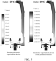
- the lead-out temperature of the vapor of the electronic vaporization device of the present invention is 69°C, the outlet temperature of the vapor is increased by 4°C compared with the existing electronic vaporization device;
- the airflow temperature of the closed end 121 of the vaporization cavity 12 of the electronic vaporization device of the present invention is about 20°C lower than that of the closed end 121 of the existing electronic vaporization device, the high-temperature region of the closed end 121 is also reduced; and moreover, after the airflow guide structure 40 is added, the heat transfer intensity between the airflow and the vaporization surface 21 increases, and the temperature distribution in the turning section is greatly improved compared with the existing electronic vaporization device.
- the e-liquid accumulation inside the vaporization cavity 12 of the electronic vaporization device of the present invention is obviously reduced, this is because after the airflow guide structure 40 is added, the airflow inside the vaporization cavity 12 changes from being disordered to being regular, and generation of eddy current inside the vaporization cavity 12 is reduced.
- the amount of carried e-liquid of the turning section is significantly increased, and the shape of "downward warping" is presented, so that the contact with the wall surface of the turning section is reduced.
Landscapes
- Catching Or Destruction (AREA)
- Cooling Or The Like Of Electrical Apparatus (AREA)
- Electrostatic Spraying Apparatus (AREA)
- Disinfection, Sterilisation Or Deodorisation Of Air (AREA)
Abstract
Description
- The present invention relates to a vaporization device, and more specifically, to an electronic vaporization device and a vaporizer thereof.
- In the interior of electronic vaporization devices with a side airway in the related art, accumulation of a large amount of high-temperature vapor is easily formed at a closed end.
- In the interior of electronic vaporization device with a side airway in the related art, a large amount of high-temperature vapor accumulation is easily formed at a closed end, which leads to two problems: one is that the vapor condenses to form condensate, and the other is that a high-temperature region is formed at the closed end, forming plastic melting, which increases a risk of miscellaneous gas and scorched smell of the vapor.
- A technical problem to be resolved in the present invention is to provide an improved vaporizer and further provide an improved electronic vaporization device.
- A technical solution adopted in the present invention to resolve the technical problem is to construct a vaporizer, including a housing and a vaporization assembly arranged in the housing, wherein a vaporization cavity configured to accommodate the vaporization assembly is provided in the housing, and an airflow channel is provided in the housing at one side of the vaporization cavity and in communication with the vaporization cavity; and
the vaporizer further includes an air inlet in communication with the vaporization cavity, and an airflow guide structure arranged in the vaporization cavity and configured to guide an airflow from the air inlet, where the airflow guide structure is arranged close to the airflow channel. - Preferably, the airflow guide structure includes an airflow guide surface facing the air inlet; and
a set angle is presented between the airflow guide surface and an air inlet end surface of the air inlet. - Preferably, the set angle is an acute angle.
- Preferably, the vaporization cavity further includes a closed region arranged opposite the airflow channel;
the airflow guide surface is arranged towards the closed region so as to guide a part of the airflow to the closed region of the vaporization cavity, and squeeze, accelerate, and guide the airflow outputted to the airflow channel from the vaporization cavity. - Preferably, the air inlet includes a central axis; and
the airflow guide structure is arranged at one side of the central axis. - Preferably, the size of the airflow guide structure is smaller than that of the vaporization cavity.
- Preferably, the airflow guide structure is arranged between the vaporization assembly and the air inlet, and a spacing is reserved between the airflow guide structure and the vaporization assembly; and
the spacing forms a communication channel that communicates the vaporization cavity with the airflow channel. - Preferably, the vaporization assembly includes a vaporization surface facing the vaporization cavity;
- the airflow guide structure further includes a flowby surface facing the vaporization surface; and
- the communication channel is arranged between the flowby surface and the vaporization surface.
- Preferably, the distance between the flowby surface and the vaporization surface is greater than zero and not greater than 2/3 of the height of the vaporization cavity.
- Preferably, a cross section of the housing includes a length direction and a width direction; and
two opposite sides of the airflow guide structure respectively extend to the side wall of the housing along the width direction of the housing. - Preferably, the airflow guide structure and the housing are integrally formed.
- Preferably, the airflow guide structure is in triangle, wedge, or trapezoid.
- Preferably, the vaporizer further includes two electrode pins conductively connected to the vaporization assembly;
- the two electrode pins are spaced apart; and
- the airflow guide structure is arranged between the two electrode pins.
- Preferably, the vaporizer further includes a base;
- the housing is sleeved over the base; and
- the air inlet is arranged on the base.
- The present invention further constructs an electronic vaporization device, including the vaporizer in the present invention and a power supply assembly connected to the vaporizer.
- The electronic vaporization device and the vaporizer thereof of the present invention are implemented to achieve the following beneficial effects: by arranging the airflow guide structure, the vaporizer can guide the airflow from the air inlet to guide a part of the airflow to a closed end of a vaporization cavity, which can avoid accumulation of a large amount of high-temperature vapor at the closed end of the vaporization cavity, and avoid generation of condensate and a risk of miscellaneous gas and scorched smell of the vapor increased by plastic melting.
- Subject matter of the present disclosure will be described in even greater detail below based on the exemplary figures. All features described and/or illustrated herein can be used alone or combined in different combinations. The features and advantages of various embodiments will become apparent by reading the following detailed description with reference to the attached drawings, which illustrate the following:
-
FIG. 1 is a schematic structural diagram of an electronic vaporization device according to some embodiments of the present invention; -
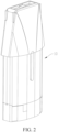
FIG. 2 is a schematic structural diagram of a vaporizer of the electronic vaporization device shown inFIG. 1 ; -
FIG. 3 is a cross-sectional view of the vaporizer shown inFIG. 2 ; -
FIG. 4 is a comparison diagram of vapor velocity field between the electronic vaporization device of the present invention and an existing electronic vaporization device; -
FIG. 5 is a comparison diagram of vapor lead-out temperature between the electronic vaporization device of the present invention and an existing electronic vaporization device; and -
FIG. 6 is a comparison diagram of e-liquid concentration field in a vaporization cavity of an electronic vaporization device of the present invention and an existing electronic vaporization device. - To provide a clearer understanding of the technical features, objectives, and effects of the present invention, specific implementations of the present invention are described in detail with reference to the accompanying drawings.
- It should be understood that terms such as "upper" and "lower" are only for the convenience of describing the technical solutions of the present invention instead of indicating that the devices or elements need to have special differences, and therefore cannot be understood as a limitation on the present invention. It should be noted that when a member is considered to be "connected" to another member, the member may be directly connected to the another member or there may be an intermediate member between the two members. Unless otherwise defined, meanings of all technical and scientific terms used herein are the same as meanings generally understood by a person skilled in the technical field to which the present invention belongs. In this specification, terms used in this specification of the present invention are merely intended to describe objectives of the specific embodiments, but are not intended to limit the present invention.
-
FIG. 1 shows some preferred embodiments of an electronic vaporization device of the present invention. Theelectronic vaporization device 100 may be configured to vaporize a liquid medium such as cigarette liquid or medicine. In some embodiments, theelectronic vaporization device 100 may include a vaporizer A and a power supply assembly B mechanically and electrically connected to the vaporizer A. The vaporizer A is configured to heat and vaporize the liquid medium, and the power supply assembly B is configured to supply power to the vaporizer. Preferably, the vaporizer A and the power supply assembly B are detachably connected. - As shown in
FIG. 2 andFIG. 3 , in some embodiments, the vaporizer A includes ahousing 10, avaporization assembly 20, anairflow guide structure 40, and abase 30. Thehousing 10 is sleeved over thebase 30 and may be configured to accommodate thevaporization assembly 20 and theairflow guide structure 40. Thevaporization assembly 20 is arranged in thehousing 10 and is configured to heat and vaporize the liquid medium. Theairflow guide structure 40 is arranged in thehousing 10 and may be configured to guide an airflow in thehousing 10. - Further, in some embodiments, the
housing 10 is in the shape of a cylinder, and thehousing 10 is sleeved on the periphery of thevaporization assembly 20. The cross section of thehousing 10 may be substantially rectangular, and the cross section of thehousing 10 may include a length direction and a width direction. Certainly, it may be understood that, in some other embodiments, the cross section of thehousing 10 may not be limited to a rectangle, and in some other embodiments, the cross section of thehousing 10 may be elliptical, the length direction may be a long axis direction, and the width direction may be a short axis direction. Aliquid storage cavity 13 may be formed inside thehousing 10, theliquid storage cavity 13 is located at the upper part of thehousing 10, and theliquid storage cavity 13 may be configured to accommodate the liquid medium. Specifically, in some embodiments, avaporization cavity 12 is further arranged in thehousing 10, and thevaporization assembly 20 may be accommodated in thevaporization cavity 12. Thevaporization cavity 12 may be located at the lower part of thehousing 10. In some embodiments, anairflow channel 11 is further arranged in thehousing 10, and theairflow channel 11 is arranged at one side of thehousing 10. Specifically, theairflow channel 11 may be located at one side of thevaporization cavity 12 and in communication with thevaporization cavity 12 to output vapor after vaporization. In some embodiments, theairflow channel 11 may extend along a longitudinal direction of thehousing 10. In some embodiments, anair outlet 15 is provided on thehousing 10. Specifically, theair outlet 15 may be provided at the top of thehousing 10, and one end of theairflow channel 11 may be in communication with theair outlet 15 to convey vapor to theair outlet 15. In some embodiments, thevaporization cavity 12 further includes aclosed region 121, and theclosed region 121 is a region arranged opposite theairflow channel 11. - Further, in some embodiments, the
vaporization assembly 20 is arranged in thevaporization cavity 12, and thevaporization assembly 20 is in liquid guide connection to theliquid storage cavity 13 in thehousing 10. In some embodiments, specifically, thehousing 10 may further include an upper base body, thevaporization assembly 20 may be accommodated in the upper base body, the upper base body is provided with a liquid flowing hole in communication with theliquid storage cavity 13, and the liquid flowing hole is in communication with thevaporization assembly 20 to convey liquid from theliquid storage cavity 13 to thevaporization assembly 20. In some embodiments, thevaporization assembly 20 includes a porous body and a heating body arranged on the porous body. The porous body may be a ceramic porous body. The heating body may be arranged on the porous body. In some embodiments, the heating body may be a heating sheet, and the heating sheet may be arranged on an end surface of the porous body towards thebase 30. Specifically, the heating body may be pasted, printed or partially embedded on the end surface of the porous body towards thebase 30. In some embodiments, thevaporization assembly 20 may include avaporization surface 21. Specifically, thevaporization surface 21 may be arranged on the porous body, and thevaporization surface 21 may be an end surface of the porous body on which the heating body is arranged. - Further, in some embodiments, the
base 30 may be located at an open end of thehousing 10 to block thehousing 10. In some embodiments, thebase 30 and thehousing 10 may be integrally formed. Certainly, it may be understood that, in some other embodiments, thebase 30 and thehousing 10 may not be limited to be integrally formed. In some embodiments, the vaporizer may further include anair inlet 31. Specifically, theair inlet 31 may be arranged on thebase 30 and located at the middle part of thebase 30. Specifically, theair inlet 31 may be arranged throughout thebase 30 along a thickness direction of thebase 30. Theair inlet 31 may be in communication with thevaporization cavity 12, and may be used for an external airflow to enter thevaporization cavity 12, to further bring out the vapor in thevaporization cavity 12. - Further, in some embodiments, the
airflow guide structure 40 may be arranged in thevaporization cavity 12 and in an air inlet direction of theair inlet 31, and arranged close to theairflow channel 11. In some embodiments, theairflow guide structure 12 may be located at one side of the central axis of theair inlet 31 and a protruding portion of the airflow guide structure is arranged not beyond the central axis to avoid blocking the central airflow. Theairflow guide structure 12 may be configured to guide the airflow from theair inlet 31 to guide a part of the airflow to a closed end of thevaporization cavity 12, which can avoid accumulation of a large amount of high-temperature vapor at the closed end of thevaporization cavity 12, and avoid generation of condensate and a risk of miscellaneous gas and scorched smell of the vapor increased by plastic melting. - Further, in some embodiments, the
airflow guide structure 40 may be in the shape of a triangle. Certainly, it may be understood that, in some other embodiments, theairflow guide structure 40 may not be limited to be in the shape of a triangle. In some other embodiments, theairflow guide structure 40 may be in a shape of a wedge or a trapezoid. In some embodiments, the size of theairflow guide structure 40 may be smaller than that of thevaporization cavity 12, thereby facilitating the flow of the vapor into theairflow channel 11. In some embodiments, theairflow guide structure 40 may be arranged between thevaporization assembly 20 and theair inlet 31, a spacing may be reserved between theairflow guide structure 40 and thevaporization assembly 20, the spacing may form acommunication channel 14, and thecommunication channel 14 is configured to communicate thevaporization cavity 12 with theairflow channel 11. - Further, in some embodiments, the
airflow guide structure 40 may include anairflow guide surface 41, and theairflow guide surface 41 is an inclined surface. Theairflow guide surface 41 may be arranged facing theair inlet 31 and may be arranged towards theclosed region 121. Theairflow guide surface 41 may be configured to guide a part of the airflow to theclosed region 121 of thevaporization cavity 12, and to squeeze, accelerate, and guide the airflow outputted to theairflow channel 11 from thevaporization cavity 12. Further, in some embodiments, a set angle α may be presented between the airflow guide surface and an air inlet end surface of theair inlet 31. In some embodiments, the set angle may be an acute angle. Specifically, in some embodiments, the set angle may be selected as an angle of 30 to 60 degrees. - Further, in some embodiments, the
airflow guide structure 40 may further include aflowby surface 42, and theflowby surface 42 may be arranged facing thevaporization surface 21. In some embodiments, theflowby surface 42 may be a flat surface, an angle may be formed between theflowby surface 42 and theairflow guide surface 41, and the angle may be equal to the set angle α. Certainly, it may be understood that, in some other embodiments, theflowby surface 42 may not be limited to a flat surface. A spacing between theflowby surface 42 and thevaporization surface 21 may form thecommunication channel 14. In some embodiments, the distance between theflowby surface 42 and thevaporization surface 21 may be greater than zero and not greater than 2/3 of the height of thevaporization cavity 12. Specifically, in some embodiments, the distance between theflowby surface 42 and the vaporization surface may be 1/3 to 2/3 of the height of the vaporization cavity. - Further, in some embodiments, two opposite sides of the
airflow guide structure 40 may respectively extend to the side wall of thehousing 10 along the width direction of thehousing 10, and may be connected to theside wall 10. In some embodiments, theairflow guide structure 40 and thehousing 10 may be integrally formed. Specifically, in some embodiments, theairflow guide structure 40 and thehousing 10 may be integrally formed through injection. - The airflow inside the
vaporization cavity 12 of the electronic vaporization device of the present invention is obviously better, the overall performance is obviously improved, and the e-liquid lead-out effect is obviously better. - As shown in
FIG. 4 , by comparing the velocity field of the vapor of the electronic vaporization device of the present invention with that of the vapor of the existing electronic vaporization device, the velocity field inside thevaporization cavity 12 changes after theairflow guide structure 40 is added, and a part of the airflow from theair inlet 31 can be drained to theclosed end 121 of thevaporization cavity 12 through turning of theairflow guide structure 40. - As shown in
FIG. 5 , by comparing the lead-out temperature of the vapor of the electronic vaporization device of the present invention with that of the vapor of the existing electronic vaporization device, firstly, the temperature of the vapor sent from theair outlet 15 of the electronic vaporization device of the present invention is 69°C, the outlet temperature of the vapor is increased by 4°C compared with the existing electronic vaporization device; secondly, the airflow temperature of theclosed end 121 of thevaporization cavity 12 of the electronic vaporization device of the present invention is about 20°C lower than that of theclosed end 121 of the existing electronic vaporization device, the high-temperature region of theclosed end 121 is also reduced; and moreover, after theairflow guide structure 40 is added, the heat transfer intensity between the airflow and thevaporization surface 21 increases, and the temperature distribution in the turning section is greatly improved compared with the existing electronic vaporization device. - As shown in
FIG. 6 , by comparing the e-liquid concentration field in the vaporization cavity of the electronic vaporization device of the present invention with that of the vaporization cavity of the existing electronic vaporization device, the e-liquid accumulation inside thevaporization cavity 12 of the electronic vaporization device of the present invention is obviously reduced, this is because after theairflow guide structure 40 is added, the airflow inside thevaporization cavity 12 changes from being disordered to being regular, and generation of eddy current inside thevaporization cavity 12 is reduced. In thevaporization cavity 12 of the electronic vaporization device of the present invention, the amount of carried e-liquid of the turning section is significantly increased, and the shape of "downward warping" is presented, so that the contact with the wall surface of the turning section is reduced. - While the invention has been illustrated and described in detail in the drawings and foregoing description, such illustration and description are to be considered illustrative or exemplary and not restrictive. It will be understood that changes and modifications may be made by those of ordinary skill within the scope of the following claims. In particular, the present invention covers further embodiments with any combination of features from different embodiments described above and below. Additionally, statements made herein characterizing the invention refer to an embodiment of the invention and not necessarily all embodiments.
Claims (15)
- A vaporizer, comprising:a housing (10); anda vaporization assembly (20) arranged in the housing (10),wherein the housing (10) is provided with a vaporization cavity (12) configured to accommodate the vaporization assembly (20), and an airflow channel (11) at one side of the vaporization cavity (12) and in communication with the vaporization cavity (12),wherein the vaporizer further comprises:an air inlet (31) in communication with the vaporization cavity (12); andan airflow guide structure (40) arranged in the vaporization cavity (12) and configured to guide an airflow from the air inlet (31),wherein the airflow guide structure (40) is arranged close to the airflow channel (11).
- The vaporizer of claim 1, wherein the airflow guide structure (40) comprises an airflow guide surface (41) facing the air inlet (31), and
wherein a set angle is presented between the airflow guide surface (41) and an air inlet end surface of the air inlet (31). - The vaporizer of claim 2, wherein the set angle is an acute angle.
- The vaporizer of claim 2, wherein the vaporization cavity (12) further comprises a closed region (121) arranged opposite the airflow channel (11), and
wherein the airflow guide surface (41) is facing the closed region (121) so as to guide a part of the airflow to the closed region (121) of the vaporization cavity (12), and squeeze, accelerate, and guide the airflow outputted to the airflow channel (11) from the vaporization cavity (12). - The vaporizer of claim 1, wherein the air inlet (31) comprises a central axis, and
the airflow guide structure (40) is arranged at one side of the central axis. - The vaporizer of claim 1, wherein the size of the airflow guide structure (40) is smaller than the size of the vaporization cavity (12).
- The vaporizer of claim 1, wherein the airflow guide structure (40) is arranged between the vaporization assembly (20) and the air inlet (31),wherein a spacing is reserved between the airflow guide structure (40) and the vaporization assembly (20), andwherein the spacing forms a communication channel (14) that communicates the vaporization cavity (12) with the airflow channel (11).
- The vaporizer of claim 7, wherein the vaporization assembly (20) comprises a vaporization surface (21) facing the vaporization cavity (12),wherein the airflow guide structure (40) comprises a flowby surface (42) facing the vaporization surface (21), andwherein the communication channel (14) is arranged between the flowby surface (42) and the vaporization surface (21).
- The vaporizer of claim 8, wherein a distance between the flowby surface (42) and the vaporization surface (21) is greater than zero and not greater than 2/3 of the height of the vaporization cavity (12).
- The vaporizer of claim 1, wherein a cross section of the housing (10) comprises a length direction and a width direction, and
wherein two opposite sides of the airflow guide structure (40) respectively extend to the side wall of the housing (10) along the width direction of the housing (10). - The vaporizer of claim 1, wherein the airflow guide structure (40) and the housing (10) are integrally formed.
- The vaporizer of claim 1, wherein the airflow guide structure (40) is in triangle, wedge or trapezoid.
- The vaporizer of claim 1, further comprising:two electrode pins (50) conductively connected to the vaporization assembly (20),wherein the two electrode pins (50) are spaced apart, andwherein the airflow guide structure (40) is arranged between the two electrode pins (50).
- The vaporizer of claim 1, further comprising:a base (30),wherein the housing (10) is sleeved over the base (30), andwherein the air inlet (31) is arranged on the base (30).
- An electronic vaporization device, comprising:the vaporizer of any one of claims 1 to 14; anda power supply assembly connected to the vaporizer.
Applications Claiming Priority (1)
| Application Number | Priority Date | Filing Date | Title |
|---|---|---|---|
| PCT/CN2020/138967 WO2022133888A1 (en) | 2020-12-24 | 2020-12-24 | Electronic atomization device and atomizer thereof |
Publications (2)
| Publication Number | Publication Date |
|---|---|
| EP4218461A1 true EP4218461A1 (en) | 2023-08-02 |
| EP4218461A4 EP4218461A4 (en) | 2023-11-08 |
Family
ID=82158632
Family Applications (1)
| Application Number | Title | Priority Date | Filing Date |
|---|---|---|---|
| EP20966460.6A Pending EP4218461A4 (en) | 2020-12-24 | 2020-12-24 | ELECTRONIC ATOMIZER DEVICE AND ATOMIZER THEREFOR |
Country Status (3)
| Country | Link |
|---|---|
| US (1) | US12582169B2 (en) |
| EP (1) | EP4218461A4 (en) |
| WO (1) | WO2022133888A1 (en) |
Family Cites Families (13)
| Publication number | Priority date | Publication date | Assignee | Title |
|---|---|---|---|---|
| EP2319334A1 (en) * | 2009-10-27 | 2011-05-11 | Philip Morris Products S.A. | A smoking system having a liquid storage portion |
| CN204146318U (en) | 2014-05-19 | 2015-02-11 | 深圳市合元科技有限公司 | Nebulizer for electronic cigarette and electronic cigarette |
| CN204070562U (en) * | 2014-08-12 | 2015-01-07 | 深圳市合元科技有限公司 | Atomizers for electronic cigarettes and electronic cigarettes |
| WO2016082108A1 (en) * | 2014-11-25 | 2016-06-02 | 朱晓春 | Heating device of electronic cigarette atomizer |
| RU2018115123A (en) * | 2015-09-25 | 2019-10-28 | ЛАББИ ХОЛДИНГС ЭлЭлСи | PERSONAL STEAM RETURN AIR INHIBITOR |
| EP3471803B1 (en) * | 2016-06-16 | 2022-08-10 | Juul Labs, Inc. | On-demand, portable convection vaporizer |
| WO2018132955A1 (en) * | 2017-01-18 | 2018-07-26 | 深圳葆威道科技有限公司 | Electronic cigarette atomizer and electronic cigarette |
| SG11201908137SA (en) * | 2017-03-16 | 2019-10-30 | Ventus Medical Ltd | A mouthpiece and heater assembly for an inhalation device |
| GB201707805D0 (en) * | 2017-05-16 | 2017-06-28 | Nicoventures Holdings Ltd | Atomiser for vapour provision device |
| CN210054649U (en) * | 2019-04-30 | 2020-02-14 | 深圳市新埃法科技有限公司 | Atomizer of electronic cigarette |
| CN211211432U (en) | 2019-10-30 | 2020-08-11 | 深圳市合元科技有限公司 | Atomization component and electronic cigarette |
| CN211353913U (en) * | 2019-11-05 | 2020-08-28 | 常州市派腾电子技术服务有限公司 | Atomization device and aerosol generation device |
| CN211910517U (en) * | 2020-01-03 | 2020-11-13 | 深圳市合元科技有限公司 | Atomizers and Electronic Cigarettes |
-
2020
- 2020-12-24 EP EP20966460.6A patent/EP4218461A4/en active Pending
- 2020-12-24 WO PCT/CN2020/138967 patent/WO2022133888A1/en not_active Ceased
-
2023
- 2023-06-15 US US18/335,438 patent/US12582169B2/en active Active
Also Published As
| Publication number | Publication date |
|---|---|
| EP4218461A4 (en) | 2023-11-08 |
| WO2022133888A1 (en) | 2022-06-30 |
| US20230320426A1 (en) | 2023-10-12 |
| US12582169B2 (en) | 2026-03-24 |
Similar Documents
| Publication | Publication Date | Title |
|---|---|---|
| CN214629861U (en) | Atomizer and electronic atomization device | |
| EP4268635A1 (en) | Electronic atomization device, and atomizer and atomization assembly thereof | |
| US20170188629A1 (en) | Aerosol-forming member | |
| CN214594164U (en) | Coil assemblies, nebulizers and electronic atomizers | |
| CN214629863U (en) | Atomizing core supporting component, atomizer and electronic atomization device | |
| CN115590254B (en) | Atomizing components, atomizers and aerosol generating devices | |
| US20230320425A1 (en) | Vaporizer and electronic vaporization device | |
| CN216019105U (en) | Atomizing core, atomizer and electronic atomization device | |
| WO2022161258A1 (en) | Atomizer and electronic atomization device | |
| US20240237747A1 (en) | Vaporizer and aerosol generation device | |
| CN216019106U (en) | Atomizing core, atomizer and electronic atomization device | |
| CN114794548A (en) | Atomizing core subassembly, atomizer and electron atomizing device | |
| CN216853796U (en) | Atomizer and aerosol generating device | |
| CN216293040U (en) | Electronic atomization device and atomizer thereof | |
| WO2024046133A1 (en) | Electromagnetic coil, atomization structure, atomizer, and electronic atomization device | |
| CN114794546A (en) | Atomizing core supporting component, atomizer and electronic atomization device | |
| CN216853795U (en) | Aerosol generating device and aerosol provision system | |
| US12582169B2 (en) | Electronic vaporization device and vaporizer thereof | |
| EP4728898A1 (en) | Electronic cigarette atomizer | |
| JP7655584B2 (en) | Atomization device with excellent atomization effect | |
| WO2024148962A1 (en) | Electronic heating atomization device with condensate recovery structure | |
| WO2024234957A1 (en) | Heating assembly, atomizer, and aerosol generating apparatus | |
| CN221902381U (en) | Electronic atomization device, atomizer and atomization assembly thereof | |
| CN219613033U (en) | Atomizer and electronic atomization device | |
| EP4205575A1 (en) | Vaporization assembly and electronic vaporization device |
Legal Events
| Date | Code | Title | Description |
|---|---|---|---|
| STAA | Information on the status of an ep patent application or granted ep patent |
Free format text: STATUS: THE INTERNATIONAL PUBLICATION HAS BEEN MADE |
|
| PUAI | Public reference made under article 153(3) epc to a published international application that has entered the european phase |
Free format text: ORIGINAL CODE: 0009012 |
|
| STAA | Information on the status of an ep patent application or granted ep patent |
Free format text: STATUS: REQUEST FOR EXAMINATION WAS MADE |
|
| 17P | Request for examination filed |
Effective date: 20230428 |
|
| AK | Designated contracting states |
Kind code of ref document: A1 Designated state(s): AL AT BE BG CH CY CZ DE DK EE ES FI FR GB GR HR HU IE IS IT LI LT LU LV MC MK MT NL NO PL PT RO RS SE SI SK SM TR |
|
| REG | Reference to a national code |
Ref country code: DE Ref legal event code: R079 Free format text: PREVIOUS MAIN CLASS: A24F0047000000 Ipc: A24F0040485000 |
|
| A4 | Supplementary search report drawn up and despatched |
Effective date: 20231009 |
|
| RIC1 | Information provided on ipc code assigned before grant |
Ipc: A24F 40/10 20200101ALN20231003BHEP Ipc: A24F 40/485 20200101AFI20231003BHEP |
|
| DAV | Request for validation of the european patent (deleted) | ||
| DAX | Request for extension of the european patent (deleted) | ||
| RAP3 | Party data changed (applicant data changed or rights of an application transferred) |
Owner name: SHENZHEN SMOORE TECHNOLOGY LIMITED |
|
| RAP3 | Party data changed (applicant data changed or rights of an application transferred) |
Owner name: SHENZHEN SMOORE TECHNOLOGY LIMITED |
|
| STAA | Information on the status of an ep patent application or granted ep patent |
Free format text: STATUS: EXAMINATION IS IN PROGRESS |
|
| 17Q | First examination report despatched |
Effective date: 20250729 |